WO2021001902A1 - Inhalateur d'arôme - Google Patents
Inhalateur d'arôme Download PDFInfo
- Publication number
- WO2021001902A1 WO2021001902A1 PCT/JP2019/026163 JP2019026163W WO2021001902A1 WO 2021001902 A1 WO2021001902 A1 WO 2021001902A1 JP 2019026163 W JP2019026163 W JP 2019026163W WO 2021001902 A1 WO2021001902 A1 WO 2021001902A1
- Authority
- WO
- WIPO (PCT)
- Prior art keywords
- flavor
- air inlet
- flow path
- heating chamber
- flavor aspirator
- Prior art date
Links
Images


Classifications
-
- A—HUMAN NECESSITIES
- A24—TOBACCO; CIGARS; CIGARETTES; SIMULATED SMOKING DEVICES; SMOKERS' REQUISITES
- A24F—SMOKERS' REQUISITES; MATCH BOXES; SIMULATED SMOKING DEVICES
- A24F40/00—Electrically operated smoking devices; Component parts thereof; Manufacture thereof; Maintenance or testing thereof; Charging means specially adapted therefor
- A24F40/40—Constructional details, e.g. connection of cartridges and battery parts
- A24F40/48—Fluid transfer means, e.g. pumps
- A24F40/485—Valves; Apertures
-
- A—HUMAN NECESSITIES
- A24—TOBACCO; CIGARS; CIGARETTES; SIMULATED SMOKING DEVICES; SMOKERS' REQUISITES
- A24F—SMOKERS' REQUISITES; MATCH BOXES; SIMULATED SMOKING DEVICES
- A24F40/00—Electrically operated smoking devices; Component parts thereof; Manufacture thereof; Maintenance or testing thereof; Charging means specially adapted therefor
- A24F40/20—Devices using solid inhalable precursors
Definitions
- the present invention relates to a flavor aspirator.
- a flavor aspirator for sucking a flavor or the like without burning the material.
- a flavor aspirator for example, a smoking material heating device that forms an aerosol by heating a smoking material composed of a cigarette containing a volatile component is known (see Patent Document 1).
- the smoking material heating device described in Patent Document 1 has a first opening for accommodating the smoking material and a second opening located on the opposite side of the first opening.
- An object of the present invention is to provide a flavor aspirator having a new structure.
- a flavor aspirator extends from the flavor source inlet, the heating chamber for heating the flavor source inserted from the flavor source inlet, the first air inlet, and the first air inlet to the heating chamber. It has a second air inlet that is spaced apart in the direction.
- a flavor aspirator is provided.
- the flavor aspirator is connected to a flavor source inlet, a heating chamber for heating the flavor source inserted from the flavor source inlet, and an end of the heating chamber opposite to the flavor source inlet.
- the tubular member having the first end portion to be formed, the first air inlet communicating with the tubular member, and the solid or liquid generated by the action of the heating chamber reach the first air inlet from the tubular member. It has a suppressing member to suppress.
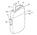
- FIG. 1A is an overall perspective view of the flavor aspirator according to the present embodiment.
- FIG. 1B is an overall perspective view of the flavor aspirator according to the present embodiment in a state where the flavor generating article is held.
- the flavor aspirator 10 according to the present embodiment is configured to generate an aerosol containing an aerosol by heating, for example, a flavor generating article 110 having a flavor source containing an aerosol source.
- the flavor aspirator 10 includes a top housing 11A, a bottom housing 11B, a cover 12, a switch 13, a lid 14, a second air inlet 15, and a cap 16.
- the top housing 11A and the bottom housing 11B are connected to each other to form the outermost outer housing 11 of the flavor aspirator 10.
- the outer housing 11 is sized to fit in the user's hand. When the user uses the flavor aspirator 10, the flavor aspirator 10 can be held by hand to suck the flavor.
- the top housing 11A has an opening (not shown).
- the cover 12 may be coupled to the top housing 11A so as to close the opening and form part of the housing.
- the cover 12 has an opening 12a into which the flavor generating article 110 can be inserted.
- the lid portion 14 is configured to open and close the opening 12a of the cover 12.
- the lid portion 14 is attached to the cover 12 and is configured to be movable along the surface of the cover 12 between the first position for closing the opening 12a and the second position for opening the opening 12a.
- the cover Thereby, the lid portion 14 can allow or limit the access of the flavor generating article 110 to the inside of the flavor aspirator 10.
- the switch 13 is used to switch the operation of the flavor aspirator 10 on and off. For example, by operating the switch 13 with the flavor generating article 110 inserted in the opening 12a as shown in FIG. 1B, power is supplied to a heating member (not shown) from a power source (not shown), and the flavor generating article 110 is supplied. Can be heated without burning. When the flavor generating article 110 is heated, the user can suck the flavor by sucking the portion (the portion shown in FIG. 1B) protruding from the flavor aspirator 10 of the flavor generating article 110.
- the second air inlet 15 is a vent for introducing air into the heating assembly 41 (see FIG. 3) housed in the internal space of the outer housing 11.
- the cap 16 is detachably configured on the bottom housing 11B. By attaching the cap 16 to the bottom housing 11B, a second air inlet 15 is formed between the bottom housing 11B and the cap 16.
- the cap 16 may have, for example, a through hole or notch (not shown).
- the longitudinal direction of the flavor aspirator 10 means the direction in which the flavor generating article 110 is inserted into the opening 12a.
- the side where a fluid such as air flows in is the upstream side
- the side where the fluid flows out is the downstream side.
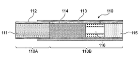
- FIG. 2 is a cross-sectional view of the flavor generating article 110.
- the flavor generating article 110 has a base material portion 110A including a filling material 111 and a first wrapping paper 112 for winding the filling material 111, and a side opposite to the base material portion 110A. It has a mouthpiece 110B, which forms an end portion of the.
- the base material portion 110A and the mouthpiece portion 110B are connected by a second wrapping paper 113 different from the first wrapping paper 112. However, the second wrapping paper 113 may be omitted, and the base material portion 110A and the mouthpiece portion 110B may be connected by using the first wrapping paper 112.
- the mouthpiece 110B in FIG. 2 has a paper tube portion 114, a filter portion 115, and a hollow segment portion 116 arranged between the paper tube portion 114 and the filter portion 115.
- the hollow segment portion 116 is composed of, for example, a packing layer having one or a plurality of hollow channels and a plug wrapper covering the filling layer. Since the packed bed has a high fiber filling density, air and aerosols flow only through the hollow channels during suction, and hardly flow inside the packed bed. In the flavor generating article 110, when it is desired to reduce the decrease due to the filtration of the aerosol component in the filter portion 115, shortening the length of the filter portion 115 and replacing it with the hollow segment portion 116 increases the delivery amount of the aerosol. It is effective for.
- the mouthpiece 110B in FIG. 2 is composed of three segments, but in the present embodiment, the mouthpiece 110B may be composed of one or two segments, or four or more. It may be composed of segments.
- the hollow segment portion 116 may be omitted, and the paper tube portion 114 and the filter portion 115 may be arranged adjacent to each other to form the mouthpiece portion 110B.
- the length of the flavor generating article 110 in the longitudinal direction is preferably 40 mm to 90 mm, more preferably 50 mm to 75 mm, and even more preferably 50 mm to 60 mm.
- the circumference of the flavor generating article 110 is preferably 15 mm to 25 mm, more preferably 17 mm to 24 mm, and even more preferably 20 mm to 23 mm.
- the length of the base material portion 110A in the flavor generating article 110 may be 20 mm
- the length of the first wrapping paper 112 may be 20 mm
- the length of the hollow segment portion 116 may be 8 mm
- the length of the filter portion 115 may be 7 mm.
- the length of these individual segments can be appropriately changed according to manufacturing suitability, required quality, and the like.
- the filler 111 of the flavor generating article 110 may contain an aerosol source that is heated at a predetermined temperature to generate an aerosol.
- the type of aerosol source is not particularly limited, and extracts from various natural products and / or their constituents can be selected depending on the intended use. Aerosol sources include, for example, glycerin, propylene glycol, triacetin, 1,3-butanediol, and mixtures thereof.
- the content of the aerosol source in the filler 111 is not particularly limited, and is usually 5% by weight or more, preferably 10% by weight or more, from the viewpoint of sufficiently generating an aerosol and imparting a good flavor and taste. Yes, and usually 50% by weight or less, preferably 20% by weight or less.
- the filling 111 of the flavor generating article 110 in the present embodiment may contain tobacco chopped as a flavor source.
- the material for chopping tobacco is not particularly limited, and known materials such as lamina and middle bone can be used.
- the range of the content of the filling material 111 in the flavor generating article 110 is, for example, 200 mg to 400 mg, preferably 250 mg to 320 mg in the case of a circumference of 22 mm and a length of 20 mm.
- the water content of the packing 111 is, for example, 8% by weight to 18% by weight, preferably 10% by weight to 16% by weight. With such a water content, the occurrence of winding stains is suppressed, and the hoisting suitability of the base material portion 110A during production is improved.
- the size of the tobacco nicks used as the filler 111 or the method for preparing the nicks there are no particular restrictions on the size of the tobacco nicks used as the filler 111 or the method for preparing the nicks.
- dried tobacco leaves may be chopped to a width of 0.8 mm to 1.2 mm.
- dried tobacco leaves may be crushed and homogenized so that the average particle size is about 20 ⁇ m to 200 ⁇ m, processed into a sheet, and chopped into a width of 0.8 mm to 1.2 mm. ..
- the sheet processed product which has been gathered without being carved may be used as the filling material 111.
- the filling material 111 may contain one kind or two or more kinds of fragrances.
- the type of the flavor is not particularly limited, but menthol is preferable from the viewpoint of imparting a good taste.
- the first wrapping paper 112 and the second wrapping paper 113 of the flavor generating article 110 can be made from a base paper having a basis weight of, for example, 20 gsm to 65 gsm, preferably 25 gsm to 45 gsm.
- the thickness of the first wrapping paper 112 and the second wrapping paper 113 is not particularly limited, but is 10 ⁇ m to 100 ⁇ m, preferably 20 ⁇ m to 75 ⁇ m from the viewpoint of rigidity, breathability, and ease of adjustment during papermaking. , More preferably 30 ⁇ m to 50 ⁇ m.
- the first wrapping paper 112 and the second wrapping paper 113 of the flavor generating article 110 may contain a filler.
- the content of the filler may be 10% by weight to 60% by weight, preferably 15% by weight to 45% by weight, based on the total weight of the first rolling paper 112 and the second rolling paper 113.
- the filler is preferably 15% by weight to 45% by weight with respect to a preferable range of basis weight (25 gsm to 45 gsm).
- the filler for example, calcium carbonate, titanium dioxide, kaolin and the like can be used.
- the paper containing such a filler exhibits a preferable white-based bright color from the viewpoint of appearance used as a rolling paper for the flavor-generating article 110, and can permanently maintain whiteness.
- the ISO whiteness of the wrapping paper can be increased to 83% or more.
- the first wrapping paper 112 and the second wrapping paper 113 preferably have a tensile strength of 8N / 15 mm or more. This tensile strength can be increased by reducing the content of the filler. Specifically, the tensile strength can be increased by reducing the content of the filler from the upper limit of the content of the filler shown in the range of each basis weight illustrated above.
- FIG. 3 is a cross-sectional view taken along the line 3-3 shown in FIG. 1A.
- the flavor aspirator 10 has an inner housing 18 provided inside the outer housing 11.
- a power supply unit 20, a circuit unit 30, and a heating device 40 are provided in the internal space of the inner housing 18.
- the circuit unit 30 includes a first circuit board 31, a second circuit board 32, and a third circuit board 33, which are electrically connected to each other.
- the first circuit board 31 is arranged so as to extend in the longitudinal direction adjacent to one surface of a substantially columnar power supply 21.
- a partition wall 34 is provided between the first circuit board 31 and the heating device 40, whereby at least a part of the area accommodating the power supply unit 20 and the first circuit board 31 is partitioned.
- the partition wall 34 may be provided with a notch, a through hole, or the like for fluid communication between the space on the power supply unit 20 side and the space on the heating device 40 side.
- the second circuit board 32 is arranged inside the top housing 11A between the cover 12 and the power supply unit 20, and extends in a direction orthogonal to the extending direction of the first circuit board 31.
- the switch 13 is arranged adjacent to the second circuit board 32. When the user presses the switch 13, a part of the switch 13 may come into contact with the second circuit board 32.
- the third circuit board 33 is arranged so as to extend in the longitudinal direction in the space formed on the opposite side of the opening 12a (see FIG. 1B) with respect to the heating device 40.
- the third circuit board 33 has a main surface on which various electronic components are mounted.
- the third circuit board 33 may be arranged in the bottom housing 11B so that its main surface is inclined with respect to the longitudinal direction. As a result, the main surface of the third circuit board 33 can be enlarged, and the space inside the bottom housing 11B can be effectively utilized.
- the first circuit board 31, the second circuit board 32, and the third circuit board 33 include, for example, a microprocessor and the like, and can control the supply of electric power from the power supply unit 20 to the heating device 40.
- the first circuit board 31, the second circuit board 32, and the third circuit board 33 can control the heating of the flavor generating article 110 by the heating device 40.
- the power supply unit 20 has a power supply 21 that is electrically connected to the first circuit board 31, the second circuit board 32, and the third circuit board 33.
- the power source 21 can be, for example, a rechargeable battery or a non-rechargeable battery.
- the power supply 21 is electrically connected to the heating device 40 via at least one of the first circuit board 31, the second circuit board 32, and the third circuit board 33.
- the power supply 21 can supply electric power to the heating device 40 so as to appropriately heat the flavor generating article 110.
- the power supply 21 is arranged in parallel with the heating device 40 adjacent to the heating device 40 in a direction orthogonal to the longitudinal direction. As a result, even if the size of the power supply 21 is increased, it is possible to prevent the length of the flavor aspirator 10 from becoming longer in the longitudinal direction.
- the flavor aspirator 10 has a terminal 22 that can be connected to an external power source.
- the terminal 22 can be connected to a cable such as a micro USB.
- the power supply 21 is a rechargeable battery
- a current can flow from the external power supply to the power supply 21 to charge the power supply 21.
- a data transmission cable such as a micro USB
- the heating device 40 includes a heating assembly 41 extending in the longitudinal direction, a curved tube 50 having a substantially L-shaped cross section, and an insertion guide member 17 having a substantially tubular shape.
- the heating assembly 41 includes a plurality of tubular members, and forms a tubular body as a whole.
- the heating assembly 41 constitutes a heating chamber capable of accommodating a part of the flavor generating article 110 inside, has a function of defining a flow path of air supplied to the flavor generating article 110, and is inserted through an opening 12a (see FIG. 1B). It has a function of heating the flavor-generating article 110 from the outer periphery.
- the insertion guide member 17 is formed of, for example, a resin material and is provided between the cover 12 having the opening 12a (see FIG. 1B) and the downstream end of the heating assembly 41 to insert the flavor generating article 110 into the heating assembly 41. To guide you.
- the curved tube 50 is formed of, for example, a resin material.
- the curved pipe 50 has a first end portion 50a and a second end portion 50b.
- the first end 50a of the curved tube 50 is connected to the upstream end of the heating assembly 41, i.e., the end opposite the opening 12a (see FIG. 1B).
- the second end 50b opens at an angle with respect to the longitudinal direction of the heating chamber of the heating assembly 41.
- the second end portion 50b is opened in a direction substantially orthogonal to the longitudinal direction of the heating chamber of the heating assembly 41. To do.
- the second end portion 50b is positioned so as to face the cap 16 attached to the bottom housing 11B.
- the cap 16 can openably cover at least a part of the second end portion 50b of the curved pipe 50.
- the curved tube 50 introduces the air supplied from the second end portion 50b into the heating chamber of the heating assembly 41 via the first end portion 50a.
- the curved pipe 50 is not limited to the L shape, and may be curved at an arbitrary angle so that the second end portion 50b faces the side surface of the outer housing 11.
- a predetermined space A1 is formed between the cap 16 and the inner housing 18 in a state where the cap 16 is attached to the outer housing 11.
- the second end portion 50b of the curved pipe 50 communicates with the space A1.
- the cap 16 can be removed from the outer housing 11 and the inside of the curved pipe 50 can be cleaned with, for example, any cleaning tool.
- a solid or liquid generated by the action of the heating chamber may accumulate in the corner portion (bottom side corner portion) distal to the heating assembly 41 of the curved tube 50.
- the corner portion of the inner surface of the curved tube 50 on the distal side with respect to the heating assembly 41 is chamfered in the longitudinal direction. This makes it easier for any cleaning tool to come into contact with the corners of the curved pipe 50.
- the bottom housing 11B is formed with a first air inlet 19 and a second air inlet 15 for introducing air into the heating assembly 41.
- the first air inlet 19 is formed on the bottom side of the bottom housing 11B. Specifically, in the present embodiment, the first air inlet 19 is formed on the inclined surface of the bottom housing 11B. In other words, the first air inlet 19 is formed on the surface of the bottom housing 11B having an angle with respect to the longitudinal direction of the heating chamber of the heating assembly 41 (the longitudinal direction of the flavor generating article 110 inserted into the heating chamber).
- the first air inlet 19 is always open without being covered with a cap or the like.
- the second air inlet 15 is formed on the side surface of the bottom housing 11B. Therefore, the first air inlet 19 is arranged apart from the second air inlet 15 in the extending direction of the heating chamber of the heating assembly 41. More specifically, the first air inlet 19 is provided distal to the opening 12a (see FIG. 1B) with respect to the second air inlet 15. Further, in the present embodiment, the second end portion 50b of the curved pipe 50 is located between the first air inlet 19 and the second air inlet 15 in the longitudinal direction. Further, the second air inlet 15 is located on the proximal end side with respect to the opening 12a with respect to the second end portion 50b of the curved pipe 50.
- a flow path 19A communicating with the first air inlet 19 is formed between the outer housing 11 and the inner housing 18. As shown in the figure, the flow path 19A communicates the first air inlet 19 with the space A1. Therefore, the air flowing in from the first air inlet 19 is supplied to the heating chamber of the heating assembly 41 through the flow path 19A, the space A1, and the curved tube 50. That is, the flow path 19A, the space A1, and the internal space of the curved tube 50 form a first air flow path that connects the first air inlet 19 and the heating chamber of the heating assembly 41.
- the heating assembly 41 extends from the opening 12a to the substantially central portion in the longitudinal direction of the flavor aspirator 10, and from the central portion in the longitudinal direction to the bottom, a space in which the heating assembly 41 does not exist (third circuit board 33).
- the space in which is placed) exists.
- the flow path 19A is provided from the first air inlet 19 to the space A1 so as not to pass around the heating assembly 41.
- the flow path 19A is located so as to be separated from the heating chamber in the extending direction of the heating chamber of the heating assembly 41. Therefore, it is suppressed that the air passing through the flow path 19A is affected by the heating assembly 41.
- the second air inlet 15 is a vent formed in the gap between the cap 16 and the outer housing 11, and communicates with the space A1. Therefore, the air flowing in from the second air inlet 15 is supplied to the heating chamber of the heating assembly 41 through the space A1 and the curved tube 50. That is, the space A1 and the internal space of the curved pipe 50 form a second air flow path that communicates the second air inlet 15 with the heating chamber of the heating assembly 41.
- the first air flow path and the second air flow path merge between the heating chamber of the heating assembly 41 and the first air inlet 19 and the second air inlet 15. Specifically, in the present embodiment, the first air flow path and the second air flow path merge in the space A1. Therefore, the air flowing in from the first air inlet 19 is mixed with the air flowing in from the second air inlet 15 in the space A1 and reaches the heating chamber through the curved pipe 50. In other words, the air flowing in from the first air inlet 19 and the second air inlet 15 both pass through the heating chamber and is used to carry the aerosol.
- the air supply ratio between the air flowing into the heating chamber from the first air inlet 19 and the air flowing into the heating chamber from the second air inlet 15 is preferably 1: 2 to 1:10, and is preferably 1: 3 to 1. It is more preferably 1: 5.
- the air supply ratio between the air flowing into the heating chamber from the first air inlet 19 and the air flowing into the heating chamber from the second air inlet 15 is preferably 1: 2 to 1:10, and is preferably 1: 3 to 1. It is more preferably 1: 5.
- the flavor generating article 110 When the flavor generating article 110 is inserted into the inside of the flavor aspirator 10 through the opening 12a of the cover 12 as shown in FIG. 1B, the flavor generating article 110 passes through the insertion guide member 17, and a part of the flavor generating article 110 is part of the heating assembly 41. Placed inside. Therefore, the insertion guide member 17 is preferably formed so that the opening on the cover 12 side is larger than the size of the opening on the heating assembly 41 side. As a result, the flavor generating article 110 can be easily inserted into the insertion guide member 17 through the opening 12a.
- FIG. 1B in a state where the flavor generating article 110 is inserted into the flavor aspirator 10 through the opening 12a, a portion of the flavor generating article 110 protruding from the flavor aspirator 10, that is, FIG.
- air flows into the inside of the heating assembly 41 from the first air inlet 19 and the second air inlet 15. The inflowing air passes through the inside of the heating assembly 41 and reaches the user's mouth together with the aerosol generated from the flavor generating article 110.
- the flavor aspirator 10 of the present embodiment when the flavor generating article 110 is heated by the heating chamber of the heating assembly 41, solids such as tobacco shavings heated from the flavor generating article 110 and an evaporated aerosol source are condensed and formed. Liquid can be generated. Such solids or liquids can reach space A1 from the heating assembly 41 via the curved tube 50. As described above, the space A1 communicates with the first air inlet 19 via the flow path 19A. Further, the first air inlet 19 is located below in the direction of gravity when the flavor aspirator 10 is used.
- the flavor aspirator 10 of the present embodiment has a suppressing member 60 that prevents the solid or liquid from reaching the first air inlet 19 from the curved tube 50.
- the restraining member 60 is arranged on a first air flow path between the heating chamber of the heating assembly 41 and the first air inlet. Specifically, in the present embodiment, the restraining member 60 is provided in the vicinity of the second end portion 50b of the curved pipe 50.
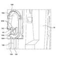
- FIG. 4 is an enlarged perspective view of the vicinity of the second end portion 50b of the curved pipe 50.
- the outer housing 11 is omitted.
- the inner housing 18 has an edge portion 18B defining the space A1 together with the cap 16 shown in FIG. 3 and the like, and a surface 18D of the inner housing 18 surrounded by the edge portion 18B.
- the edge portion 18B of the present embodiment projects from the surface of the inner housing 18 toward the cap 16 along a shape in which the short side is substantially arcuate and the long side is substantially linear.
- the inner housing 18 has a pair of edge portions 18A that define the flow path 19A together with the outer housing 11.
- the edge portion 18A extends from the edge portion 18B to the vicinity of the first air inlet 19, and is configured to guide the air flowing in from the first air inlet 19 to the space A1.
- the inner housing 18 has an opening 18C that communicates with the opening of the second end 50b of the curved pipe 50.
- the restraining member 60 is provided around the opening 18C of the inner housing 18.
- the restraining member 60 is a pair of an arcuate convex portion 60A located on the first air inlet 19 side of the opening 18C along the opening shape of the opening 18C and a pair extending from the arcuate convex portion 60A to the second air inlet 15 side. It has a linear convex portion 60B. Both the arcuate convex portion 60A and the linear convex portion 60B project from the surface 18D of the inner housing 18 toward the cap 16.
- the restraining member 60 (the arcuate convex portion 60A in the illustrated example) is farther from the opening 12a than the second end portion 50b of the curved pipe 50 in the longitudinal direction of the heating chamber of the heating assembly 41. It will be located on the rank side.
- the linear convex portion 60B extends from the opening 18C toward the second air inlet 15. Therefore, the restraining member 60 surrounds the opening 18C and the second end 50b of the curved pipe 50, and opens the opening 12a side (upper side in the drawing) of the second end 50b.
- the arc-shaped convex portion 60A is configured so that the air is divided into two and flows from the first air inlet 19 to the second end portion 50b.
- the present invention is not limited to this, and the restraining member 60 may be configured so that the air from the first air inlet 19 to the second end portion 50b does not separate into two hands.
- the air flow can be blocked and the air flow can be made one.
- a convex portion extending in the lateral direction is provided in FIG. 4, and one end of the convex portion is coupled to the edge portion 18B to block the air flow.
- air can flow into the second end portion 50b of the curved pipe 50 from the other end side of the convex portion.
- the restraining member 60 is provided in the inner housing 18, but the present invention is not limited to this.
- the restraining member 60 may be provided on the cap 16 so as to prevent the solid or liquid generated by the action of the heating chamber from reaching the first air inlet 19 from the curved pipe 50, for example.
- the flavor aspirator 10 of the present embodiment has a first air inlet 19 and a second air inlet 15 that is separated from the first air inlet 19 in the longitudinal direction.
- the user grips the side surface of the outer housing 11. At this time, if the user's hand covers a part of the second air inlet 15, the ventilation resistance of the second air flow path through which the air flowing in from the second air inlet 15 passes can be increased. According to the present embodiment, a stable amount of air can be supplied from the first air inlet 19 to the heating assembly 41 even when a part of the second air inlet 15 is covered by the user's hand. ..
- a part of the first air inlet 19 may be covered. In this case, even if the ventilation resistance of the first air flow path through which the air flowing in from the first air inlet 19 passes increases, a stable amount of air can be supplied from the second air inlet 15 to the heating assembly 41. it can.
- the flavor aspirator 10 of the present embodiment has the suppressing member 60, it is possible to prevent the solid or liquid generated by the action of the heating chamber from reaching the first air inlet 19 from the curved tube 50.
- the flavor generating article 110 has been described as having a stick shape, but the present invention is not limited to this, and for example, a cartridge containing a flavor source and an aerosol source inside a capsule may be adopted.
- the distance between the opening of the second end portion 50b and the outer housing 11 can be made relatively short.
- the inside of the curved pipe 50 can be easily accessed from the opening of the second end portion 50b, and the maintenance of the inside of the curved pipe 50 can be facilitated.
- a flavor aspirator is provided. This flavor aspirator extends from the flavor source inlet, the heating chamber for heating the flavor source inserted from the flavor source inlet, the first air inlet, and the first air inlet to the heating chamber. It has a second air inlet that is spaced apart in the direction.
- the gist of the second form is that, in the first form, the first air inlet is provided distal to the flavor source inlet and outlet of the second air inlet.
- the third form has, in the first form or the second form, a first air flow path communicating with the first air inlet and a second air flow path communicating with the second air inlet, and the first The gist is that the 1 air flow path and the second air flow path are configured to merge.
- the first air flow path communicates the first air inlet with the heating chamber
- the second air flow path communicates with the second air inlet and the heating chamber.
- the gist is that the first air flow path and the second air flow path are configured to merge between the heating chamber, the first air inlet, and the second air inlet. To do.
- the fifth form has a housing provided with the flavor source inlet and the first air inlet in any of the first to fourth forms, the first air inlet in the longitudinal direction of the heating chamber.
- the gist is that it is formed on the surface of the housing having an angle with respect to the housing.
- the sixth form has, in any one of the first to fifth forms, a curved tube connected to an end of the heating chamber opposite to the flavor source inlet, the first air inlet and the said.
- the gist of the second air inlet is that it communicates with the curved pipe.
- the curved tube is formed in an L shape, and the curved tube has an opening end portion that opens in a direction substantially orthogonal to the longitudinal direction of the heating chamber.
- the gist of the flavor aspirator is that it has a lid that covers at least a part of the open end portion so as to be openable and closable.
- the eighth form is a sixth form quoting the second form, in which the curved tube has a first end portion connected to the heating chamber and an open end portion opposite to the first end portion.
- the gist of the flavor aspirator is that it has a space where the first air flow path and the second air flow path meet, and a lid that covers at least a part of the space so as to be openable and closable.
- the ninth form is any of the first to eighth forms, and the gist is that the flavor source is tobacco.
- a flavor aspirator is provided.
- the flavor aspirator is connected to a flavor source inlet, a heating chamber for heating the flavor source inserted from the flavor source inlet, and an end of the heating chamber opposite to the flavor source inlet.
- the tubular member having the first end portion to be formed, the first air inlet communicating with the tubular member, and the solid or liquid generated by the action of the heating chamber reach the first air inlet from the tubular member. It has a suppressing member to suppress.
- the eleventh form is the tenth form, and the gist is that the air flowing in from the first air inlet goes around the suppressing member and flows into the inside of the tubular member.
- the tubular member in the tenth form or the eleventh form, has a second end portion opposite to the first end portion, and the second end portion is in the longitudinal direction of the heating chamber.
- the gist is to open at an angle to the opening.
- At least a part of the suppressing member is located distal to the flavor source receiving port with respect to the second end portion of the tubular member in the longitudinal direction of the heating chamber.
- the gist is to be located.
- the tubular member is formed in an L shape, and the second end portion of the tubular member is in a direction substantially orthogonal to the longitudinal direction of the heating chamber.
- the gist is to open to.
- the fifteenth form is any of the twelfth to fourteenth forms, and the gist is that the flavor aspirator has a lid that covers at least a part of the second end portion of the tubular member so as to be openable and closable.
- the 16th form has, in the 15th form, a housing in which the flavor source inlet and the first air inlet are formed, and a second air inlet formed in a gap between the lid and the housing. It is a summary.
- the seventeenth form is any of the twelfth to sixteenth forms, wherein the suppressing member surrounds the second end portion of the tubular member and the flavor source receiving / receiving side of the second end portion.
- the gist is to open it up.
- Flavor aspirator 11 ... Outer housing 12 ... Cover 12a ... Opening 15 ... Second air inlet 19 ... First air inlet 19A ... Flow path 41 ... Heating assembly 50 ... Curved tube 50a ... First end 50b ... Second end Part 60 ... Suppressing member 110 ... Flavor generating article A1 ... Space
Abstract
L'invention concerne une cartouche ayant une nouvelle structure et un inhalateur d'arôme. Cet inhalateur d'arôme comprend : un orifice de réception de source d'arôme ; une chambre de chauffage pour chauffer une source d'arôme insérée à partir de l'orifice de réception de source d'arôme ; une première entrée d'air ; et une seconde entrée d'air espacée de la première entrée d'air dans la direction dans laquelle s'étend la chambre de chauffage.
Priority Applications (4)
| Application Number | Priority Date | Filing Date | Title |
|---|---|---|---|
| PCT/JP2019/026163 WO2021001902A1 (fr) | 2019-07-01 | 2019-07-01 | Inhalateur d'arôme |
| EP19936445.6A EP3995016A4 (fr) | 2019-07-01 | 2019-07-01 | Inhalateur d'arôme |
| JP2021529578A JP7267422B2 (ja) | 2019-07-01 | 2019-07-01 | 香味吸引器 |
| TW108128301A TW202102141A (zh) | 2019-07-01 | 2019-08-08 | 香味吸嚐器 |
Applications Claiming Priority (1)
| Application Number | Priority Date | Filing Date | Title |
|---|---|---|---|
| PCT/JP2019/026163 WO2021001902A1 (fr) | 2019-07-01 | 2019-07-01 | Inhalateur d'arôme |
Publications (1)
| Publication Number | Publication Date |
|---|---|
| WO2021001902A1 true WO2021001902A1 (fr) | 2021-01-07 |
Family
ID=74100964
Family Applications (1)
| Application Number | Title | Priority Date | Filing Date |
|---|---|---|---|
| PCT/JP2019/026163 WO2021001902A1 (fr) | 2019-07-01 | 2019-07-01 | Inhalateur d'arôme |
Country Status (4)
| Country | Link |
|---|---|
| EP (1) | EP3995016A4 (fr) |
| JP (1) | JP7267422B2 (fr) |
| TW (1) | TW202102141A (fr) |
| WO (1) | WO2021001902A1 (fr) |
Citations (4)
| Publication number | Priority date | Publication date | Assignee | Title |
|---|---|---|---|---|
| JP2014533932A (ja) * | 2011-10-06 | 2014-12-18 | エスアイエス リソーセズ リミテッドSis Resources Ltd. | 喫煙システム |
| WO2018055761A1 (fr) * | 2016-09-26 | 2018-03-29 | 日本たばこ産業株式会社 | Inhalateur d'arôme |
| JP2018522551A (ja) | 2015-06-26 | 2018-08-16 | ブリティッシュ アメリカン タバコ (インヴェストメンツ) リミテッドBritish American Tobacco (Investments) Limited | 喫煙材加熱装置 |
| JP2019505192A (ja) * | 2015-12-22 | 2019-02-28 | フィリップ・モーリス・プロダクツ・ソシエテ・アノニム | 液体ポンプを備えた電気的に動作するエアロゾル発生システム |
Family Cites Families (5)
| Publication number | Priority date | Publication date | Assignee | Title |
|---|---|---|---|---|
| JP2017536109A (ja) * | 2014-10-29 | 2017-12-07 | ジェイティー インターナショナル エス.エイ. | エアロゾル生成装置 |
| MX2018004861A (es) * | 2015-11-02 | 2018-08-01 | Philip Morris Products Sa | Sistema generador de aerosol que comprende un elemento vibratorio. |
| US10905164B2 (en) * | 2017-07-30 | 2021-02-02 | Wallace Dray Moorman | Vaporizer having adjustable atomizer and removable screen |
| GB201718923D0 (en) * | 2017-11-16 | 2018-01-03 | British American Tobacco Investments Ltd | Consumable ventilation control |
| WO2019115475A1 (fr) * | 2017-12-13 | 2019-06-20 | Philip Morris Products S.A. | Dispositif de production d'aérosol à chauffage efficace |
-
2019
- 2019-07-01 EP EP19936445.6A patent/EP3995016A4/fr not_active Withdrawn
- 2019-07-01 WO PCT/JP2019/026163 patent/WO2021001902A1/fr unknown
- 2019-07-01 JP JP2021529578A patent/JP7267422B2/ja active Active
- 2019-08-08 TW TW108128301A patent/TW202102141A/zh unknown
Patent Citations (4)
| Publication number | Priority date | Publication date | Assignee | Title |
|---|---|---|---|---|
| JP2014533932A (ja) * | 2011-10-06 | 2014-12-18 | エスアイエス リソーセズ リミテッドSis Resources Ltd. | 喫煙システム |
| JP2018522551A (ja) | 2015-06-26 | 2018-08-16 | ブリティッシュ アメリカン タバコ (インヴェストメンツ) リミテッドBritish American Tobacco (Investments) Limited | 喫煙材加熱装置 |
| JP2019505192A (ja) * | 2015-12-22 | 2019-02-28 | フィリップ・モーリス・プロダクツ・ソシエテ・アノニム | 液体ポンプを備えた電気的に動作するエアロゾル発生システム |
| WO2018055761A1 (fr) * | 2016-09-26 | 2018-03-29 | 日本たばこ産業株式会社 | Inhalateur d'arôme |
Non-Patent Citations (1)
| Title |
|---|
| See also references of EP3995016A4 |
Also Published As
| Publication number | Publication date |
|---|---|
| EP3995016A1 (fr) | 2022-05-11 |
| EP3995016A4 (fr) | 2023-01-25 |
| JPWO2021001902A1 (fr) | 2021-01-07 |
| TW202102141A (zh) | 2021-01-16 |
| JP7267422B2 (ja) | 2023-05-01 |
Similar Documents
| Publication | Publication Date | Title |
|---|---|---|
| EP3614870B1 (fr) | Dispositif de distribution d'aérosol | |
| WO2010095660A1 (fr) | Inhalateur d'arome de type non chauffant | |
| KR20110115143A (ko) | 비가열형 담배 향미 흡인기 | |
| KR20210057772A (ko) | 벤츄리 요소를 포함하는 에어로졸 발생 시스템 | |
| WO2021001904A1 (fr) | Inhalateur d'arôme | |
| WO2021001902A1 (fr) | Inhalateur d'arôme | |
| KR102354450B1 (ko) | 에어로졸 생성 장치 | |
| KR102140799B1 (ko) | 사용자에게 향상된 흡연 경험을 제공하는 흡연물품용 보조장치 | |
| JP7274668B2 (ja) | 吸引装置 | |
| WO2021001908A1 (fr) | Inhalateur d'arôme et élément de guidage d'insertion | |
| EP3995014A1 (fr) | Ensemble de chauffage et inhalateur d'arôme | |
| US20230380493A1 (en) | Heat-not-burn tobacco product and heat-not-burn tobacco stick | |
| WO2022230089A1 (fr) | Système à fumer, kit de dispositif, article consommable et combiné, et procédé permettant d'obtenir une sensation d'atteinte d'une extrémité terminale et une sensation prédictive d'atteinte d'extrémité terminale |
Legal Events
| Date | Code | Title | Description |
|---|---|---|---|
| 121 | Ep: the epo has been informed by wipo that ep was designated in this application |
Ref document number: 19936445 Country of ref document: EP Kind code of ref document: A1 |
|
| ENP | Entry into the national phase |
Ref document number: 2021529578 Country of ref document: JP Kind code of ref document: A |
|
| NENP | Non-entry into the national phase |
Ref country code: DE |
|
| ENP | Entry into the national phase |
Ref document number: 2019936445 Country of ref document: EP Effective date: 20220201 |