WO2020262483A1 - Honeycomb layered body and production method therefor - Google Patents
Honeycomb layered body and production method therefor Download PDFInfo
- Publication number
- WO2020262483A1 WO2020262483A1 PCT/JP2020/024885 JP2020024885W WO2020262483A1 WO 2020262483 A1 WO2020262483 A1 WO 2020262483A1 JP 2020024885 W JP2020024885 W JP 2020024885W WO 2020262483 A1 WO2020262483 A1 WO 2020262483A1
- Authority
- WO
- WIPO (PCT)
- Prior art keywords
- honeycomb
- honeycomb core
- surface material
- porous sheet
- laminate
- Prior art date
Links
Images


Classifications
-
- B—PERFORMING OPERATIONS; TRANSPORTING
- B32—LAYERED PRODUCTS
- B32B—LAYERED PRODUCTS, i.e. PRODUCTS BUILT-UP OF STRATA OF FLAT OR NON-FLAT, e.g. CELLULAR OR HONEYCOMB, FORM
- B32B3/00—Layered products comprising a layer with external or internal discontinuities or unevennesses, or a layer of non-planar form; Layered products having particular features of form
- B32B3/10—Layered products comprising a layer with external or internal discontinuities or unevennesses, or a layer of non-planar form; Layered products having particular features of form characterised by a discontinuous layer, i.e. formed of separate pieces of material
- B32B3/12—Layered products comprising a layer with external or internal discontinuities or unevennesses, or a layer of non-planar form; Layered products having particular features of form characterised by a discontinuous layer, i.e. formed of separate pieces of material characterised by a layer of regularly- arranged cells, e.g. a honeycomb structure
-
- B—PERFORMING OPERATIONS; TRANSPORTING
- B32—LAYERED PRODUCTS
- B32B—LAYERED PRODUCTS, i.e. PRODUCTS BUILT-UP OF STRATA OF FLAT OR NON-FLAT, e.g. CELLULAR OR HONEYCOMB, FORM
- B32B5/00—Layered products characterised by the non- homogeneity or physical structure, i.e. comprising a fibrous, filamentary, particulate or foam layer; Layered products characterised by having a layer differing constitutionally or physically in different parts
- B32B5/02—Layered products characterised by the non- homogeneity or physical structure, i.e. comprising a fibrous, filamentary, particulate or foam layer; Layered products characterised by having a layer differing constitutionally or physically in different parts characterised by structural features of a fibrous or filamentary layer
-
- B—PERFORMING OPERATIONS; TRANSPORTING
- B29—WORKING OF PLASTICS; WORKING OF SUBSTANCES IN A PLASTIC STATE IN GENERAL
- B29C—SHAPING OR JOINING OF PLASTICS; SHAPING OF MATERIAL IN A PLASTIC STATE, NOT OTHERWISE PROVIDED FOR; AFTER-TREATMENT OF THE SHAPED PRODUCTS, e.g. REPAIRING
- B29C70/00—Shaping composites, i.e. plastics material comprising reinforcements, fillers or preformed parts, e.g. inserts
- B29C70/68—Shaping composites, i.e. plastics material comprising reinforcements, fillers or preformed parts, e.g. inserts by incorporating or moulding on preformed parts, e.g. inserts or layers, e.g. foam blocks
-
- B—PERFORMING OPERATIONS; TRANSPORTING
- B29—WORKING OF PLASTICS; WORKING OF SUBSTANCES IN A PLASTIC STATE IN GENERAL
- B29C—SHAPING OR JOINING OF PLASTICS; SHAPING OF MATERIAL IN A PLASTIC STATE, NOT OTHERWISE PROVIDED FOR; AFTER-TREATMENT OF THE SHAPED PRODUCTS, e.g. REPAIRING
- B29C70/00—Shaping composites, i.e. plastics material comprising reinforcements, fillers or preformed parts, e.g. inserts
- B29C70/04—Shaping composites, i.e. plastics material comprising reinforcements, fillers or preformed parts, e.g. inserts comprising reinforcements only, e.g. self-reinforcing plastics
- B29C70/06—Fibrous reinforcements only
- B29C70/08—Fibrous reinforcements only comprising combinations of different forms of fibrous reinforcements incorporated in matrix material, forming one or more layers, and with or without non-reinforced layers
- B29C70/086—Fibrous reinforcements only comprising combinations of different forms of fibrous reinforcements incorporated in matrix material, forming one or more layers, and with or without non-reinforced layers and with one or more layers of pure plastics material, e.g. foam layers
-
- B—PERFORMING OPERATIONS; TRANSPORTING
- B29—WORKING OF PLASTICS; WORKING OF SUBSTANCES IN A PLASTIC STATE IN GENERAL
- B29C—SHAPING OR JOINING OF PLASTICS; SHAPING OF MATERIAL IN A PLASTIC STATE, NOT OTHERWISE PROVIDED FOR; AFTER-TREATMENT OF THE SHAPED PRODUCTS, e.g. REPAIRING
- B29C70/00—Shaping composites, i.e. plastics material comprising reinforcements, fillers or preformed parts, e.g. inserts
- B29C70/04—Shaping composites, i.e. plastics material comprising reinforcements, fillers or preformed parts, e.g. inserts comprising reinforcements only, e.g. self-reinforcing plastics
- B29C70/06—Fibrous reinforcements only
- B29C70/08—Fibrous reinforcements only comprising combinations of different forms of fibrous reinforcements incorporated in matrix material, forming one or more layers, and with or without non-reinforced layers
- B29C70/088—Fibrous reinforcements only comprising combinations of different forms of fibrous reinforcements incorporated in matrix material, forming one or more layers, and with or without non-reinforced layers and with one or more layers of non-plastics material or non-specified material, e.g. supports
-
- B—PERFORMING OPERATIONS; TRANSPORTING
- B29—WORKING OF PLASTICS; WORKING OF SUBSTANCES IN A PLASTIC STATE IN GENERAL
- B29C—SHAPING OR JOINING OF PLASTICS; SHAPING OF MATERIAL IN A PLASTIC STATE, NOT OTHERWISE PROVIDED FOR; AFTER-TREATMENT OF THE SHAPED PRODUCTS, e.g. REPAIRING
- B29C70/00—Shaping composites, i.e. plastics material comprising reinforcements, fillers or preformed parts, e.g. inserts
- B29C70/04—Shaping composites, i.e. plastics material comprising reinforcements, fillers or preformed parts, e.g. inserts comprising reinforcements only, e.g. self-reinforcing plastics
- B29C70/28—Shaping operations therefor
- B29C70/40—Shaping or impregnating by compression not applied
- B29C70/42—Shaping or impregnating by compression not applied for producing articles of definite length, i.e. discrete articles
- B29C70/46—Shaping or impregnating by compression not applied for producing articles of definite length, i.e. discrete articles using matched moulds, e.g. for deforming sheet moulding compounds [SMC] or prepregs
-
- B—PERFORMING OPERATIONS; TRANSPORTING
- B29—WORKING OF PLASTICS; WORKING OF SUBSTANCES IN A PLASTIC STATE IN GENERAL
- B29C—SHAPING OR JOINING OF PLASTICS; SHAPING OF MATERIAL IN A PLASTIC STATE, NOT OTHERWISE PROVIDED FOR; AFTER-TREATMENT OF THE SHAPED PRODUCTS, e.g. REPAIRING
- B29C70/00—Shaping composites, i.e. plastics material comprising reinforcements, fillers or preformed parts, e.g. inserts
- B29C70/68—Shaping composites, i.e. plastics material comprising reinforcements, fillers or preformed parts, e.g. inserts by incorporating or moulding on preformed parts, e.g. inserts or layers, e.g. foam blocks
- B29C70/86—Incorporated in coherent impregnated reinforcing layers, e.g. by winding
-
- B—PERFORMING OPERATIONS; TRANSPORTING
- B29—WORKING OF PLASTICS; WORKING OF SUBSTANCES IN A PLASTIC STATE IN GENERAL
- B29D—PRODUCING PARTICULAR ARTICLES FROM PLASTICS OR FROM SUBSTANCES IN A PLASTIC STATE
- B29D24/00—Producing articles with hollow walls
- B29D24/002—Producing articles with hollow walls formed with structures, e.g. cores placed between two plates or sheets, e.g. partially filled
- B29D24/005—Producing articles with hollow walls formed with structures, e.g. cores placed between two plates or sheets, e.g. partially filled the structure having joined ribs, e.g. honeycomb
-
- B—PERFORMING OPERATIONS; TRANSPORTING
- B32—LAYERED PRODUCTS
- B32B—LAYERED PRODUCTS, i.e. PRODUCTS BUILT-UP OF STRATA OF FLAT OR NON-FLAT, e.g. CELLULAR OR HONEYCOMB, FORM
- B32B15/00—Layered products comprising a layer of metal
- B32B15/04—Layered products comprising a layer of metal comprising metal as the main or only constituent of a layer, which is next to another layer of the same or of a different material
- B32B15/046—Layered products comprising a layer of metal comprising metal as the main or only constituent of a layer, which is next to another layer of the same or of a different material of foam
-
- B—PERFORMING OPERATIONS; TRANSPORTING
- B32—LAYERED PRODUCTS
- B32B—LAYERED PRODUCTS, i.e. PRODUCTS BUILT-UP OF STRATA OF FLAT OR NON-FLAT, e.g. CELLULAR OR HONEYCOMB, FORM
- B32B15/00—Layered products comprising a layer of metal
- B32B15/14—Layered products comprising a layer of metal next to a fibrous or filamentary layer
-
- B—PERFORMING OPERATIONS; TRANSPORTING
- B32—LAYERED PRODUCTS
- B32B—LAYERED PRODUCTS, i.e. PRODUCTS BUILT-UP OF STRATA OF FLAT OR NON-FLAT, e.g. CELLULAR OR HONEYCOMB, FORM
- B32B15/00—Layered products comprising a layer of metal
- B32B15/20—Layered products comprising a layer of metal comprising aluminium or copper
-
- B—PERFORMING OPERATIONS; TRANSPORTING
- B32—LAYERED PRODUCTS
- B32B—LAYERED PRODUCTS, i.e. PRODUCTS BUILT-UP OF STRATA OF FLAT OR NON-FLAT, e.g. CELLULAR OR HONEYCOMB, FORM
- B32B27/00—Layered products comprising a layer of synthetic resin
- B32B27/06—Layered products comprising a layer of synthetic resin as the main or only constituent of a layer, which is next to another layer of the same or of a different material
- B32B27/065—Layered products comprising a layer of synthetic resin as the main or only constituent of a layer, which is next to another layer of the same or of a different material of foam
-
- B—PERFORMING OPERATIONS; TRANSPORTING
- B32—LAYERED PRODUCTS
- B32B—LAYERED PRODUCTS, i.e. PRODUCTS BUILT-UP OF STRATA OF FLAT OR NON-FLAT, e.g. CELLULAR OR HONEYCOMB, FORM
- B32B3/00—Layered products comprising a layer with external or internal discontinuities or unevennesses, or a layer of non-planar form; Layered products having particular features of form
- B32B3/26—Layered products comprising a layer with external or internal discontinuities or unevennesses, or a layer of non-planar form; Layered products having particular features of form characterised by a particular shape of the outline of the cross-section of a continuous layer; characterised by a layer with cavities or internal voids ; characterised by an apertured layer
- B32B3/28—Layered products comprising a layer with external or internal discontinuities or unevennesses, or a layer of non-planar form; Layered products having particular features of form characterised by a particular shape of the outline of the cross-section of a continuous layer; characterised by a layer with cavities or internal voids ; characterised by an apertured layer characterised by a layer comprising a deformed thin sheet, i.e. the layer having its entire thickness deformed out of the plane, e.g. corrugated, crumpled
-
- B—PERFORMING OPERATIONS; TRANSPORTING
- B32—LAYERED PRODUCTS
- B32B—LAYERED PRODUCTS, i.e. PRODUCTS BUILT-UP OF STRATA OF FLAT OR NON-FLAT, e.g. CELLULAR OR HONEYCOMB, FORM
- B32B3/00—Layered products comprising a layer with external or internal discontinuities or unevennesses, or a layer of non-planar form; Layered products having particular features of form
- B32B3/26—Layered products comprising a layer with external or internal discontinuities or unevennesses, or a layer of non-planar form; Layered products having particular features of form characterised by a particular shape of the outline of the cross-section of a continuous layer; characterised by a layer with cavities or internal voids ; characterised by an apertured layer
- B32B3/30—Layered products comprising a layer with external or internal discontinuities or unevennesses, or a layer of non-planar form; Layered products having particular features of form characterised by a particular shape of the outline of the cross-section of a continuous layer; characterised by a layer with cavities or internal voids ; characterised by an apertured layer characterised by a layer formed with recesses or projections, e.g. hollows, grooves, protuberances, ribs
-
- B—PERFORMING OPERATIONS; TRANSPORTING
- B32—LAYERED PRODUCTS
- B32B—LAYERED PRODUCTS, i.e. PRODUCTS BUILT-UP OF STRATA OF FLAT OR NON-FLAT, e.g. CELLULAR OR HONEYCOMB, FORM
- B32B37/00—Methods or apparatus for laminating, e.g. by curing or by ultrasonic bonding
- B32B37/06—Methods or apparatus for laminating, e.g. by curing or by ultrasonic bonding characterised by the heating method
-
- B—PERFORMING OPERATIONS; TRANSPORTING
- B32—LAYERED PRODUCTS
- B32B—LAYERED PRODUCTS, i.e. PRODUCTS BUILT-UP OF STRATA OF FLAT OR NON-FLAT, e.g. CELLULAR OR HONEYCOMB, FORM
- B32B37/00—Methods or apparatus for laminating, e.g. by curing or by ultrasonic bonding
- B32B37/10—Methods or apparatus for laminating, e.g. by curing or by ultrasonic bonding characterised by the pressing technique, e.g. using action of vacuum or fluid pressure
-
- B—PERFORMING OPERATIONS; TRANSPORTING
- B32—LAYERED PRODUCTS
- B32B—LAYERED PRODUCTS, i.e. PRODUCTS BUILT-UP OF STRATA OF FLAT OR NON-FLAT, e.g. CELLULAR OR HONEYCOMB, FORM
- B32B37/00—Methods or apparatus for laminating, e.g. by curing or by ultrasonic bonding
- B32B37/14—Methods or apparatus for laminating, e.g. by curing or by ultrasonic bonding characterised by the properties of the layers
- B32B37/16—Methods or apparatus for laminating, e.g. by curing or by ultrasonic bonding characterised by the properties of the layers with all layers existing as coherent layers before laminating
- B32B37/18—Methods or apparatus for laminating, e.g. by curing or by ultrasonic bonding characterised by the properties of the layers with all layers existing as coherent layers before laminating involving the assembly of discrete sheets or panels only
- B32B37/182—Methods or apparatus for laminating, e.g. by curing or by ultrasonic bonding characterised by the properties of the layers with all layers existing as coherent layers before laminating involving the assembly of discrete sheets or panels only one or more of the layers being plastic
- B32B37/185—Laminating sheets, panels or inserts between two discrete plastic layers
-
- B—PERFORMING OPERATIONS; TRANSPORTING
- B32—LAYERED PRODUCTS
- B32B—LAYERED PRODUCTS, i.e. PRODUCTS BUILT-UP OF STRATA OF FLAT OR NON-FLAT, e.g. CELLULAR OR HONEYCOMB, FORM
- B32B38/00—Ancillary operations in connection with laminating processes
- B32B38/08—Impregnating
-
- B—PERFORMING OPERATIONS; TRANSPORTING
- B32—LAYERED PRODUCTS
- B32B—LAYERED PRODUCTS, i.e. PRODUCTS BUILT-UP OF STRATA OF FLAT OR NON-FLAT, e.g. CELLULAR OR HONEYCOMB, FORM
- B32B38/00—Ancillary operations in connection with laminating processes
- B32B38/18—Handling of layers or the laminate
- B32B38/1866—Handling of layers or the laminate conforming the layers or laminate to a convex or concave profile
-
- B—PERFORMING OPERATIONS; TRANSPORTING
- B32—LAYERED PRODUCTS
- B32B—LAYERED PRODUCTS, i.e. PRODUCTS BUILT-UP OF STRATA OF FLAT OR NON-FLAT, e.g. CELLULAR OR HONEYCOMB, FORM
- B32B5/00—Layered products characterised by the non- homogeneity or physical structure, i.e. comprising a fibrous, filamentary, particulate or foam layer; Layered products characterised by having a layer differing constitutionally or physically in different parts
- B32B5/02—Layered products characterised by the non- homogeneity or physical structure, i.e. comprising a fibrous, filamentary, particulate or foam layer; Layered products characterised by having a layer differing constitutionally or physically in different parts characterised by structural features of a fibrous or filamentary layer
- B32B5/022—Non-woven fabric
-
- B—PERFORMING OPERATIONS; TRANSPORTING
- B32—LAYERED PRODUCTS
- B32B—LAYERED PRODUCTS, i.e. PRODUCTS BUILT-UP OF STRATA OF FLAT OR NON-FLAT, e.g. CELLULAR OR HONEYCOMB, FORM
- B32B5/00—Layered products characterised by the non- homogeneity or physical structure, i.e. comprising a fibrous, filamentary, particulate or foam layer; Layered products characterised by having a layer differing constitutionally or physically in different parts
- B32B5/02—Layered products characterised by the non- homogeneity or physical structure, i.e. comprising a fibrous, filamentary, particulate or foam layer; Layered products characterised by having a layer differing constitutionally or physically in different parts characterised by structural features of a fibrous or filamentary layer
- B32B5/024—Woven fabric
-
- B—PERFORMING OPERATIONS; TRANSPORTING
- B32—LAYERED PRODUCTS
- B32B—LAYERED PRODUCTS, i.e. PRODUCTS BUILT-UP OF STRATA OF FLAT OR NON-FLAT, e.g. CELLULAR OR HONEYCOMB, FORM
- B32B5/00—Layered products characterised by the non- homogeneity or physical structure, i.e. comprising a fibrous, filamentary, particulate or foam layer; Layered products characterised by having a layer differing constitutionally or physically in different parts
- B32B5/18—Layered products characterised by the non- homogeneity or physical structure, i.e. comprising a fibrous, filamentary, particulate or foam layer; Layered products characterised by having a layer differing constitutionally or physically in different parts characterised by features of a layer of foamed material
-
- B—PERFORMING OPERATIONS; TRANSPORTING
- B32—LAYERED PRODUCTS
- B32B—LAYERED PRODUCTS, i.e. PRODUCTS BUILT-UP OF STRATA OF FLAT OR NON-FLAT, e.g. CELLULAR OR HONEYCOMB, FORM
- B32B5/00—Layered products characterised by the non- homogeneity or physical structure, i.e. comprising a fibrous, filamentary, particulate or foam layer; Layered products characterised by having a layer differing constitutionally or physically in different parts
- B32B5/22—Layered products characterised by the non- homogeneity or physical structure, i.e. comprising a fibrous, filamentary, particulate or foam layer; Layered products characterised by having a layer differing constitutionally or physically in different parts characterised by the presence of two or more layers which are next to each other and are fibrous, filamentary, formed of particles or foamed
- B32B5/24—Layered products characterised by the non- homogeneity or physical structure, i.e. comprising a fibrous, filamentary, particulate or foam layer; Layered products characterised by having a layer differing constitutionally or physically in different parts characterised by the presence of two or more layers which are next to each other and are fibrous, filamentary, formed of particles or foamed one layer being a fibrous or filamentary layer
- B32B5/245—Layered products characterised by the non- homogeneity or physical structure, i.e. comprising a fibrous, filamentary, particulate or foam layer; Layered products characterised by having a layer differing constitutionally or physically in different parts characterised by the presence of two or more layers which are next to each other and are fibrous, filamentary, formed of particles or foamed one layer being a fibrous or filamentary layer another layer next to it being a foam layer
-
- B—PERFORMING OPERATIONS; TRANSPORTING
- B32—LAYERED PRODUCTS
- B32B—LAYERED PRODUCTS, i.e. PRODUCTS BUILT-UP OF STRATA OF FLAT OR NON-FLAT, e.g. CELLULAR OR HONEYCOMB, FORM
- B32B5/00—Layered products characterised by the non- homogeneity or physical structure, i.e. comprising a fibrous, filamentary, particulate or foam layer; Layered products characterised by having a layer differing constitutionally or physically in different parts
- B32B5/22—Layered products characterised by the non- homogeneity or physical structure, i.e. comprising a fibrous, filamentary, particulate or foam layer; Layered products characterised by having a layer differing constitutionally or physically in different parts characterised by the presence of two or more layers which are next to each other and are fibrous, filamentary, formed of particles or foamed
- B32B5/24—Layered products characterised by the non- homogeneity or physical structure, i.e. comprising a fibrous, filamentary, particulate or foam layer; Layered products characterised by having a layer differing constitutionally or physically in different parts characterised by the presence of two or more layers which are next to each other and are fibrous, filamentary, formed of particles or foamed one layer being a fibrous or filamentary layer
- B32B5/26—Layered products characterised by the non- homogeneity or physical structure, i.e. comprising a fibrous, filamentary, particulate or foam layer; Layered products characterised by having a layer differing constitutionally or physically in different parts characterised by the presence of two or more layers which are next to each other and are fibrous, filamentary, formed of particles or foamed one layer being a fibrous or filamentary layer another layer next to it also being fibrous or filamentary
- B32B5/275—Layered products characterised by the non- homogeneity or physical structure, i.e. comprising a fibrous, filamentary, particulate or foam layer; Layered products characterised by having a layer differing constitutionally or physically in different parts characterised by the presence of two or more layers which are next to each other and are fibrous, filamentary, formed of particles or foamed one layer being a fibrous or filamentary layer another layer next to it also being fibrous or filamentary characterised by one woven fabric layer next to a non-woven fabric layer
-
- B—PERFORMING OPERATIONS; TRANSPORTING
- B32—LAYERED PRODUCTS
- B32B—LAYERED PRODUCTS, i.e. PRODUCTS BUILT-UP OF STRATA OF FLAT OR NON-FLAT, e.g. CELLULAR OR HONEYCOMB, FORM
- B32B2250/00—Layers arrangement
- B32B2250/40—Symmetrical or sandwich layers, e.g. ABA, ABCBA, ABCCBA
-
- B—PERFORMING OPERATIONS; TRANSPORTING
- B32—LAYERED PRODUCTS
- B32B—LAYERED PRODUCTS, i.e. PRODUCTS BUILT-UP OF STRATA OF FLAT OR NON-FLAT, e.g. CELLULAR OR HONEYCOMB, FORM
- B32B2260/00—Layered product comprising an impregnated, embedded, or bonded layer wherein the layer comprises an impregnation, embedding, or binder material
- B32B2260/02—Composition of the impregnated, bonded or embedded layer
- B32B2260/021—Fibrous or filamentary layer
- B32B2260/023—Two or more layers
-
- B—PERFORMING OPERATIONS; TRANSPORTING
- B32—LAYERED PRODUCTS
- B32B—LAYERED PRODUCTS, i.e. PRODUCTS BUILT-UP OF STRATA OF FLAT OR NON-FLAT, e.g. CELLULAR OR HONEYCOMB, FORM
- B32B2260/00—Layered product comprising an impregnated, embedded, or bonded layer wherein the layer comprises an impregnation, embedding, or binder material
- B32B2260/04—Impregnation, embedding, or binder material
- B32B2260/046—Synthetic resin
-
- B—PERFORMING OPERATIONS; TRANSPORTING
- B32—LAYERED PRODUCTS
- B32B—LAYERED PRODUCTS, i.e. PRODUCTS BUILT-UP OF STRATA OF FLAT OR NON-FLAT, e.g. CELLULAR OR HONEYCOMB, FORM
- B32B2262/00—Composition or structural features of fibres which form a fibrous or filamentary layer or are present as additives
- B32B2262/02—Synthetic macromolecular fibres
- B32B2262/0261—Polyamide fibres
-
- B—PERFORMING OPERATIONS; TRANSPORTING
- B32—LAYERED PRODUCTS
- B32B—LAYERED PRODUCTS, i.e. PRODUCTS BUILT-UP OF STRATA OF FLAT OR NON-FLAT, e.g. CELLULAR OR HONEYCOMB, FORM
- B32B2262/00—Composition or structural features of fibres which form a fibrous or filamentary layer or are present as additives
- B32B2262/02—Synthetic macromolecular fibres
- B32B2262/0276—Polyester fibres
- B32B2262/0284—Polyethylene terephthalate [PET] or polybutylene terephthalate [PBT]
-
- B—PERFORMING OPERATIONS; TRANSPORTING
- B32—LAYERED PRODUCTS
- B32B—LAYERED PRODUCTS, i.e. PRODUCTS BUILT-UP OF STRATA OF FLAT OR NON-FLAT, e.g. CELLULAR OR HONEYCOMB, FORM
- B32B2262/00—Composition or structural features of fibres which form a fibrous or filamentary layer or are present as additives
- B32B2262/10—Inorganic fibres
- B32B2262/101—Glass fibres
-
- B—PERFORMING OPERATIONS; TRANSPORTING
- B32—LAYERED PRODUCTS
- B32B—LAYERED PRODUCTS, i.e. PRODUCTS BUILT-UP OF STRATA OF FLAT OR NON-FLAT, e.g. CELLULAR OR HONEYCOMB, FORM
- B32B2262/00—Composition or structural features of fibres which form a fibrous or filamentary layer or are present as additives
- B32B2262/10—Inorganic fibres
- B32B2262/106—Carbon fibres, e.g. graphite fibres
-
- B—PERFORMING OPERATIONS; TRANSPORTING
- B32—LAYERED PRODUCTS
- B32B—LAYERED PRODUCTS, i.e. PRODUCTS BUILT-UP OF STRATA OF FLAT OR NON-FLAT, e.g. CELLULAR OR HONEYCOMB, FORM
- B32B2266/00—Composition of foam
- B32B2266/02—Organic
- B32B2266/0214—Materials belonging to B32B27/00
- B32B2266/0278—Polyurethane
-
- B—PERFORMING OPERATIONS; TRANSPORTING
- B32—LAYERED PRODUCTS
- B32B—LAYERED PRODUCTS, i.e. PRODUCTS BUILT-UP OF STRATA OF FLAT OR NON-FLAT, e.g. CELLULAR OR HONEYCOMB, FORM
- B32B2266/00—Composition of foam
- B32B2266/02—Organic
- B32B2266/0214—Materials belonging to B32B27/00
- B32B2266/0285—Condensation resins of aldehydes, e.g. with phenols, ureas, melamines
-
- B—PERFORMING OPERATIONS; TRANSPORTING
- B32—LAYERED PRODUCTS
- B32B—LAYERED PRODUCTS, i.e. PRODUCTS BUILT-UP OF STRATA OF FLAT OR NON-FLAT, e.g. CELLULAR OR HONEYCOMB, FORM
- B32B2266/00—Composition of foam
- B32B2266/06—Open cell foam
-
- B—PERFORMING OPERATIONS; TRANSPORTING
- B32—LAYERED PRODUCTS
- B32B—LAYERED PRODUCTS, i.e. PRODUCTS BUILT-UP OF STRATA OF FLAT OR NON-FLAT, e.g. CELLULAR OR HONEYCOMB, FORM
- B32B2307/00—Properties of the layers or laminate
- B32B2307/30—Properties of the layers or laminate having particular thermal properties
- B32B2307/306—Resistant to heat
- B32B2307/3065—Flame resistant or retardant, fire resistant or retardant
-
- B—PERFORMING OPERATIONS; TRANSPORTING
- B32—LAYERED PRODUCTS
- B32B—LAYERED PRODUCTS, i.e. PRODUCTS BUILT-UP OF STRATA OF FLAT OR NON-FLAT, e.g. CELLULAR OR HONEYCOMB, FORM
- B32B2307/00—Properties of the layers or laminate
- B32B2307/50—Properties of the layers or laminate having particular mechanical properties
- B32B2307/54—Yield strength; Tensile strength
-
- B—PERFORMING OPERATIONS; TRANSPORTING
- B32—LAYERED PRODUCTS
- B32B—LAYERED PRODUCTS, i.e. PRODUCTS BUILT-UP OF STRATA OF FLAT OR NON-FLAT, e.g. CELLULAR OR HONEYCOMB, FORM
- B32B2307/00—Properties of the layers or laminate
- B32B2307/50—Properties of the layers or laminate having particular mechanical properties
- B32B2307/546—Flexural strength; Flexion stiffness
-
- B—PERFORMING OPERATIONS; TRANSPORTING
- B32—LAYERED PRODUCTS
- B32B—LAYERED PRODUCTS, i.e. PRODUCTS BUILT-UP OF STRATA OF FLAT OR NON-FLAT, e.g. CELLULAR OR HONEYCOMB, FORM
- B32B2307/00—Properties of the layers or laminate
- B32B2307/70—Other properties
- B32B2307/718—Weight, e.g. weight per square meter
-
- B—PERFORMING OPERATIONS; TRANSPORTING
- B32—LAYERED PRODUCTS
- B32B—LAYERED PRODUCTS, i.e. PRODUCTS BUILT-UP OF STRATA OF FLAT OR NON-FLAT, e.g. CELLULAR OR HONEYCOMB, FORM
- B32B2307/00—Properties of the layers or laminate
- B32B2307/70—Other properties
- B32B2307/72—Density
-
- B—PERFORMING OPERATIONS; TRANSPORTING
- B32—LAYERED PRODUCTS
- B32B—LAYERED PRODUCTS, i.e. PRODUCTS BUILT-UP OF STRATA OF FLAT OR NON-FLAT, e.g. CELLULAR OR HONEYCOMB, FORM
- B32B2307/00—Properties of the layers or laminate
- B32B2307/70—Other properties
- B32B2307/732—Dimensional properties
-
- B—PERFORMING OPERATIONS; TRANSPORTING
- B32—LAYERED PRODUCTS
- B32B—LAYERED PRODUCTS, i.e. PRODUCTS BUILT-UP OF STRATA OF FLAT OR NON-FLAT, e.g. CELLULAR OR HONEYCOMB, FORM
- B32B2307/00—Properties of the layers or laminate
- B32B2307/70—Other properties
- B32B2307/748—Releasability
Definitions
- the present invention relates to a honeycomb laminate and a method for producing the same.
- honeycomb laminate in which a surface material impregnated and cured with a thermosetting resin is laminated on both sides of a honeycomb core is known. Since this honeycomb laminate is lightweight and has high rigidity, it is used in fields such as aircraft, automobiles, and construction.
- Cocure molding is known as the production of honeycomb laminates.
- prepregs impregnated with thermosetting resin are placed on both sides of the honeycomb core, and the thermosetting resin of the prepreg is cured to form a surface material and bond the surface material (prepreg) and the honeycomb core. At the same time.
- the honeycomb laminate is adhered to the surface material (prepreg) at the end of the wall of the honeycomb core by the thermosetting resin of the prepreg, and the surface material is formed in the part (hollow part) in the cell surrounded by the wall of the honeycomb core. Not glued to. Therefore, in order to increase the adhesive strength between the honeycomb core and the surface material, it is important to satisfactorily form the fillet formed between the wall of the honeycomb core and the surface material.
- the fillet is formed by raising a thermosetting resin so as to sandwich the end of the wall of the honeycomb core from the surface material (prepreg).
- the fillet raised from the surface material only sandwiches the end of the wall of the honeycomb core.
- the adhesive strength between the and the honeycomb core was not high.
- the present invention has been made in view of the above points, and an object of the present invention is to provide a honeycomb laminate having high adhesive strength between the surface material and the honeycomb core and the surface material not easily peeling off from the honeycomb core, and a method for manufacturing the same.
- the surface material is made of a member for a surface material in which a porous sheet is laminated on a carbon fiber body in which fibers of a carbon fiber woven fabric or a unidirectional carbon fiber sheet are laminated on each other, and a thermosetting resin is impregnated and cured.
- the porous sheet and the honeycomb core come into contact with each other, At the contact position between the porous sheet and the honeycomb core, a honeycomb laminate is provided in which the honeycomb core bites into the porous sheet and the thermosetting resin exuded from the porous sheet is cured.
- Honeycomb Honeycomb.
- a honeycomb laminate having irregularities on at least one surface has a honeycomb core and a surface material laminated on both sides of the honeycomb core.
- the surface material is made of a thermosetting resin impregnated and cured.
- a honeycomb laminate is provided in which the honeycomb core is crushed in the thickness direction.
- the surface material is made of a member for a surface material in which a porous sheet is laminated on a carbon fiber body in which fibers of a carbon fiber woven fabric or a unidirectional carbon fiber sheet are laminated on each other, and a thermosetting resin is impregnated and cured.
- An impregnation step of impregnating the surface material member with the thermosetting resin A laminating step of arranging the surface material member impregnated with the thermosetting resin on both sides of the honeycomb core so that the porous sheet comes into contact with the honeycomb core to obtain a laminate for compression heating.
- the honeycomb core By compressing and heating the laminate for compression and heating, the honeycomb core is made to bite into the porous sheet, and the thermosetting resin is exuded from the porous sheet at the biting portion, and the exuded heat.
- the honeycomb laminate has a honeycomb core and a surface material laminated on both sides of the honeycomb core.
- a concave portion is formed on the surface of the laminate for compression heating at the portion, and a concave-convex shape composed of the concave portion and the convex portion adjacent to the concave portion is formed, and the thermosetting in the impregnated surface material member is performed.
- a compression heating shaping step of curing the thermosetting resin and the thermosetting resin exuded from the impregnated surface material member, and integrating the honeycomb core and the surface material formed from the surface material member.
- a honeycomb laminate having high adhesive strength between the surface material and the honeycomb core and the surface material not easily peeling off from the honeycomb core, and a method for manufacturing the same.
- FIG. 1st Embodiment of this invention It is a top view which shows by cutting out a part of the honeycomb laminated body in 1st Embodiment of this invention. It is a 2-2 sectional view of FIG. It is a figure which shows the impregnation process in the manufacturing method of 1st Embodiment of this invention. It is a figure which shows the laminating process in the manufacturing method of 1st Embodiment of this invention. It is a figure which shows the heat compression process in the manufacturing method of 1st Embodiment of this invention. It is a table which shows the structure and evaluation of an Example and a comparative example. It is a top view which shows by cutting out a part of the honeycomb laminated body in 2nd Embodiment of this invention.
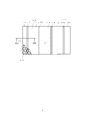
- the honeycomb laminate 10 shown in FIGS. 1 and 2 has a honeycomb core 11 and a surface material 21 laminated and integrated on both sides of the honeycomb core 11.
- the honeycomb core 11 and the surface material 21 are adhered to each other with high adhesive strength (peeling strength of the surface material).
- the honeycomb core 11 has a plurality of cells 15 whose spaces are partitioned by the wall 13.
- the honeycomb core 11 has a cell 15 having a hexagonal shape (honeycomb) as in the present embodiment, as well as a quadrangle, a triangle, a pentagon, an octagonal shape, a flute shape (corrugated shape), a circular shape, and the like. , Not limited. From the viewpoint of the strength of the honeycomb core 11 and the ease of manufacturing, it is preferable that the cell has a hexagonal planar shape.
- the material of the honeycomb core 11 examples include paper, metal, resin, ceramic, and aramid fiber sheet, but aluminum (aluminum honeycomb core), which is particularly lightweight and nonflammable, is preferable.
- aluminum honeycomb core which is particularly lightweight and nonflammable, is preferable.
- the cell size d of the honeycomb core 11 is preferably in the range of 1/32 to 1/1 inch, more preferably 1/32 to 1/2 inch.
- the height (thickness) of the honeycomb core 11 is preferably in the range of 2 to 150 mm because if it is too low, it becomes heavy for its bulk, and if it is too high, the strength of the honeycomb core 11 decreases.
- the surface material 21 is made of a surface material member 27 impregnated with a thermosetting resin and cured.
- the surface material member 27 is formed by laminating a porous sheet 25 on a carbon fiber body 23 in which fibrous bodies of a carbon fiber woven fabric or a unidirectional carbon fiber sheet are laminated to each other.
- the thickness of the surface material 21 is preferably 0.2 to 3.0 mm on each side in order to prevent natural deformation such as dents and to be lightweight.
- the carbon fiber body 23 is not limited to one layer on each side of the honeycomb core 11, and may be composed of a plurality of layers (multilayers).
- the carbon fiber body 23 is excellent in light weight and high rigidity.
- the carbon fiber body is particularly preferably a woven fabric in which the fibers are not only in one direction (woven fabric). Woven or the like is suitable. Further, the carbon fiber body 23 preferably has a fiber weight of 90 to 400 g / m 2 from the viewpoint of impregnation with a thermosetting resin and rigidity.
- the carbon fiber body 23 is a carbon fiber woven fabric or a unidirectional carbon fiber sheet in which fiber bodies are laminated with each other, and is a carbon fiber body in which carbon fiber woven fabrics are laminated with each other.
- the carbon fiber body 23 is a carbon fiber body in which a carbon fiber woven fabric and a unidirectional carbon fiber sheet are laminated. Further, it is a carbon fiber body in which unidirectional carbon fiber sheets are laminated so as to intersect the directions of each other.
- the porous sheet 25 is made of a foam or a non-woven fabric.
- the honeycomb core 11 bites into the porous sheet 25 at the contact position where the honeycomb core 11 abuts. If the thickness of the porous sheet 25 is too thin, the honeycomb core 11 cannot bite into it. On the other hand, if the thickness of the porous sheet 25 is too thick, it becomes heavy, and the thermosetting resin does not seep into the honeycomb core 11 sufficiently, so that the increase in adhesive strength becomes ineffective. Therefore, the thickness of the porous sheet 25 is preferably 0.5 to 2 mm.
- a foam having an open cell structure is preferable in order to enable impregnation with a thermosetting resin, and examples thereof include a urethane resin foam and a melamine resin foam.
- the melamine resin foam has good flame retardancy, it is suitable when the honeycomb laminate 10 is required to have flame retardancy. If the density of the foam (JIS K 7222) is too low, the impregnation property and retention of the thermosetting resin will be poor, while if it is too high, the honeycomb core will not be able to bite. Therefore, the density of the foam is preferably 5 to 100 kg / m 3 , more preferably 20 to 80 kg / m 3 .
- non-woven fabric examples include carbon fiber non-woven fabric, glass non-woven fabric, nylon non-woven fabric, PET non-woven fabric and the like. Further, if the basis weight of the non-woven fabric is too small, the impregnation property and the retention property are deteriorated, while if it is too large, the honeycomb core cannot be bitten, so 2 to 200 g / m 2 is preferable.
- a fillet 17 is formed at a position where the honeycomb core 11 bites into the porous sheet 25.
- the porous sheet 25 is compressed and the thermosetting resin exudes, and the exuded thermosetting resin rises along the wall 13 in which the honeycomb core 11 bites and sandwiches the end portion of the wall 13. It is formed by hardening in a state of being.
- thermosetting resin is not particularly limited, but in order to increase the rigidity of the honeycomb laminate 10, the thermosetting resin itself needs to have a certain degree of rigidity, and the epoxy resin, the phenol resin, the epoxy resin and the phenol resin It can be selected from the group consisting of a mixture and a urethane resin.
- the thermosetting resin is preferably flame-retardant. Phenolic resins are suitable because they have good flame retardancy.
- the impregnation amount of the thermosetting resin is preferably 50 to 80% by weight with respect to the surface material member after impregnation.
- thermosetting resin contained in the surface material member 27 exudes from the porous sheet 25 during the production of the honeycomb laminate 10 and comes into contact with the honeycomb core 11. Further, the fillet 17 is formed and cured.
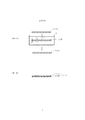
- the method for producing the honeycomb laminate 10 of the present embodiment includes an impregnation step, a lamination step, and a compression heating step.
- a surface material member in which a porous sheet is laminated on a carbon fiber body is impregnated with a thermosetting resin to prepare an impregnated surface material member.
- An example of the impregnation process is shown below.
- the carbon fiber body 23A is impregnated with the thermosetting resin F to form the impregnated carbon fiber body 23B.
- the carbon fiber body 23A and the thermosetting resin F are the same as the carbon fiber body and the thermosetting resin described in the honeycomb laminate 10.
- the thermosetting resin F used at the time of impregnation is an uncured liquid.
- the porous sheet 25A is laminated on one side of the impregnated carbon fiber body 23B to form the impregnated surface material member 27A.
- the porous sheet 25A can be attached to one side of the impregnated carbon fiber 23B due to the tackiness (adhesiveness) of the thermosetting resin adhering to the surface of the impregnated carbon fiber 23B.
- the porous sheet 25A laminated on the impregnated carbon fiber body 23B is impregnated with the thermosetting resin adhering to the surface of the impregnated carbon fiber body 23B in contact with the porous sheet 25A.
- the porous sheet 25A is the same as the porous sheet described in the honeycomb laminate 10.
- thermosetting resin F is preferably dissolved in a solvent in order to facilitate impregnation, and after impregnation, the impregnated surface material member 27A is dried at a low temperature at which the curing reaction of the thermosetting resin F does not occur. Thereby, the solvent is removed.
- the impregnation means is a method of immersing the carbon fiber 23A in a tank containing a liquid thermosetting resin F, a method of spraying the thermosetting resin F onto the carbon fiber 23A by spraying, and a method of spraying the thermosetting resin F with carbon by a roll coater. It can be carried out by an appropriate method such as a method of applying to the fiber body 23A.
- the impregnated carbon fiber 23B is laminated and then the porous sheet 25A is laminated.
- the surface material member 27A is formed.
- the carbon fiber body 23A and the porous sheet 25A may be impregnated with the thermosetting resin F and then laminated to form the impregnated surface material member 27A.
- the porous sheet 25A may be laminated on the carbon fiber body 23A in advance to prepare a surface material member before impregnation, and the surface material member may be impregnated with a thermosetting resin to form an impregnated surface material member 27A. Good.
- impregnated surface material members 27A are arranged on both sides of the honeycomb core 11A to obtain a compressed heating laminated body 10A.
- the impregnated surface material member 27A is arranged so that the porous sheet 25A is located inside (honeycomb core 11A side) and the porous sheet 25A and the honeycomb core 11A are in contact with each other.
- the honeycomb core 11A is as described in the honeycomb laminate 10.
- the impregnated surface material member 27A, the honeycomb core 11A, and the impregnated surface material member 27A are placed on the upper surface of the lower mold 31 of the press molding machine used in the next compression heating step (FIG. 5) in this order. It may be repeated.
- the impregnated surface material member 27A and the honeycomb core 11A preferably have the same plane size.
- the compression heating laminate 10A is compressed and heated by the lower mold 31 and the upper mold 33 of the press molding machine.
- the honeycomb laminate is actually manufactured by changing the distance between the lower mold 31 and the upper mold 33 in advance, and the thickness of the surface material in the obtained honeycomb laminate is measured to obtain the desired surface material thickness. Find the spacing between mold 31 and upper mold 33.
- spacers are installed at appropriate positions between the lower mold 31 and the upper mold 33 so that the lower mold 31 and the upper mold 33 have a predetermined interval.
- the method for heating the laminate for compression heating is not particularly limited, but it is easy to provide heating means such as a heater on the lower mold 31 and the upper mold 33 and heat the laminate through the lower mold 31 and the upper mold 33. ..
- the heating temperature is equal to or higher than the curing reaction temperature of the thermosetting resin.
- thermosetting resin impregnated in the impregnated carbon fiber 23B is extruded, and the porous sheet 25A in contact with the impregnated carbon fiber 23B is extruded. Is impregnated, and the entire impregnated surface material member 27A is impregnated.
- the porous sheet 25A is already impregnated with the thermosetting resin in the impregnation step, but the porous sheet 25A is further impregnated with the thermosetting resin by this compression heating step.
- the portion of the porous sheet 25A in contact with the honeycomb core 11A is compressed and dented by the end of the wall of the honeycomb core 11A, and the honeycomb core 11A is dented in the recessed portion of the porous sheet 25A. Bite into. At the portion where the honeycomb core 11A bites, the thermosetting resin in the porous sheet 25A exudes, and the exuded thermosetting resin rises along the wall of the honeycomb core 11A and sandwiches the edge of the wall. It becomes.
- thermosetting resin starts a curing reaction by heating, a surface material 21 is formed from the impregnated surface material member 27A, and a honeycomb laminate 10 in which the surface material 21 and the honeycomb core 11A (11) are integrated is formed. Ru. Further, at the contact position between the porous sheet 25A and the honeycomb core 11A, the exuded thermosetting resin rises along the wall of the honeycomb core 11A and cures while sandwiching the end of the wall of the honeycomb core 11A. Will form the fillet 17. After that, the heat compression is released to obtain the honeycomb laminate 10. (Example)
- a twill-woven carbon fiber woven fabric (manufactured by Teijin Co., Ltd., product name; W-3161, fiber weight 200 g / m 2) ) was soaked and taken out to prepare an impregnated carbon fiber woven fabric.
- the carbon fiber woven fabric one cut into a flat size of 200 ⁇ 350 mm (weight 14 g / sheet) was used.
- Example 1 As porous sheets, in Examples 1 to 3 and Examples 5 to 6, sheet-shaped soft urethane foam (communication bubble structure, manufactured by Inoac Corporation, product name: MF-50, thickness 0.7 mm, density 30 kg / m) 3 ) was used, and in Example 4, a carbon non-woven fabric (manufactured by Awa Paper Co., Ltd., product name: CARMIX CFRP, thickness 1 mm, basis weight 120 g / m 2 ) was used. The porous sheet was not attached to the impregnated carbon fiber woven fabric for the comparative example.
- sheet-shaped soft urethane foam communication bubble structure, manufactured by Inoac Corporation, product name: MF-50, thickness 0.7 mm, density 30 kg / m) 3
- Example 4 a carbon non-woven fabric (manufactured by Awa Paper Co., Ltd., product name: CARMIX CFRP, thickness 1 mm, basis weight 120 g / m 2 ) was used.
- the impregnated carbon fiber woven fabric to which the porous sheet is attached and the impregnated carbon fiber woven fabric to which the porous sheet is not attached are naturally dried at room temperature of 25 ° C. for 2 hours, and further in an atmosphere of 60 ° C.
- the prepreg with the porous sheet and the prepreg without the porous sheet were prepared by drying in 1 hour.
- honeycomb core for each example and comparative example, an aluminum honeycomb (thickness 3 mm, weight 37 g / sheet) having a cell size of 1/8 inch and an aluminum having a cell size of 1 inch, which were cut into a plane size of 200 ⁇ 350 mm, respectively.
- a honeycomb (thickness 3 mm, weight 40 g) and an aluminum honeycomb (thickness 2 mm, weight 25 g) having a cell size of 1/8 inch were used.
- the required number of prepregs without a porous sheet, prepregs with a porous sheet, aluminum honeycomb, and a porous sheet was arranged in this order.
- the porous sheet was brought into contact with the aluminum honeycomb.
- the compression-heating laminate in which the prepreg was arranged on both sides of the honeycomb core was set on the lower mold so that the honeycomb core and the porous sheet of the prepreg were in contact with each other.
- the laminate of the prepreg without the porous sheet and the prepreg with the porous sheet corresponds to the impregnated surface material member.
- the required number of prepregs without a porous sheet, the aluminum honeycomb, and the required number of prepregs without a porous sheet are arranged in this order, and a laminate for compression heating is set in the lower mold. did.
- SUS spacers having a thickness corresponding to the thickness of the honeycomb laminates of each example and the comparative example are placed at the four corners of the lower mold of the press molding machine, and the laminate for compression heating on the lower mold is placed at 150 ° C. for 30 minutes.
- the laminate for compression heating was heated by the cast heaters attached to the lower mold and the upper mold for press molding.
- a surface pressure (press pressure) of 10 MPa was applied to Examples 1 and 2, Examples 4 to 6 and Comparative Example, while a surface pressure (press pressure) of 15 MPa was applied to Example 3 to apply an upper mold (press pressure). It was pressed with a flat plate) to compress and heat it.
- honeycomb laminates of the examples a surface material obtained by curing a laminate (member for an impregnated surface material) of a prepreg without a porous body and a prepreg with a porous sheet is laminated on both sides of an aluminum honeycomb. It is integrated.
- the aluminum honeycomb bites into the porous sheet, and fillets are formed at the biting positions.
- the honeycomb laminate of the comparative example a surface material obtained by laminating and curing a plurality of non-porous prepregs is laminated on both sides of an aluminum honeycomb and integrated, and there is no biting of the honeycomb core and a fillet. Was not formed.
- the flexural modulus of the surface material was measured for the honeycomb laminates of each Example and Comparative Example. As a result, when the flexural modulus is 20 MPa or more and there is no peeling of the honeycomb laminate, the evaluation is set to " ⁇ ", and in other cases (the flexural modulus is less than 20 MPa or / and there is peeling of the honeycomb laminate). Case), the evaluation was set to "x".
- the flexural modulus was measured based on JIS K 7074.
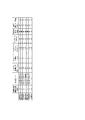
- Figure 6 shows the configuration and evaluation of each example and comparative example. All of the honeycomb laminates of Examples 1 to 6 had a flexural modulus of 25 to 31 GPa and no peeling of the surface material, and were evaluated as “ ⁇ ”. In the honeycomb laminates of Examples 1 to 6, the peel strength of the surface material is high and the rigidity is high due to both the increase in the adhesive strength due to the honeycomb core biting into the porous sheet of the surface material and the increase in the adhesive strength due to the fillet. It was expensive.
- the honeycomb laminate of the comparative example had a flexural modulus of 6 GPa and was evaluated as "x".
- the surface material prepreg
- the honeycomb core does not bite into the surface material and no fillet is formed.
- the adhesive strength of the surface material was low, the surface material was easily peeled off, and the rigidity was greatly reduced.
- the honeycomb core bites into the porous sheet of the surface material laminated on both sides of the honeycomb core to form a fillet. Therefore, the honeycomb core bites into the honeycomb core.
- the adhesion between the honeycomb core and the surface material can be strengthened (the peel strength of the surface material is large).
- the method for producing the honeycomb laminate 10 of the present invention it is not necessary to form a surface material in advance and bond the surface material to the honeycomb core with an adhesive. That is, in the method for producing the honeycomb laminate 10 of the present invention, when the thermosetting resin of the prepreg is cured, the surface material (prepreg) can be formed and the honeycomb core can be adhered at the same time, which streamlines the manufacturing process. it can.
- the honeycomb laminate 110 having irregularities 118 and 119 on the surface and the manufacturing method thereof will be described with reference to FIGS. 7 to 11.
- the description of the same structure and manufacturing method as that of the first embodiment described above will be omitted.
- the end of the wall of the honeycomb core is sandwiched between the fillets raised from the inner surface (back surface) of the surface material.
- the adhesive strength was not high because it was only present.
- the second embodiment of the present invention has been made in view of the above points, and it is not necessary to form irregularities on the surface of the honeycomb core in advance, and at the same time as laminating and integrating the surface material and the honeycomb core, the honeycomb Provided are a honeycomb laminate capable of forming irregularities on the core and providing irregularities on the surface of the laminate, and a method for producing the same.
- the honeycomb laminate 110 of the second embodiment has irregularities 118 and 119 on its surface.
- the honeycomb laminate 110 has a honeycomb core 111 and a surface material 121 laminated and integrated on both sides of the honeycomb core 111.
- Concave 118 and convex 119 are formed on the surface of the honeycomb laminate 110, and the adhesive strength between the honeycomb core 111 and the surface material 121 (peeling strength of the surface material) is enhanced.
- the convex 119 is a portion adjacent to the concave 118, and the concave 118 is formed on the surface so that the portion adjacent to the concave 118 is relatively high and the convex 119 is formed.
- the honeycomb core 111 of the present embodiment is in a state in which the wall 113A (see FIG. 8) located at the concave portion 118 on the surface is compressed and crushed in the thickness (height) direction of the honeycomb core 111. If the cell size (opening) d of the honeycomb core 111 is too small, the weight of the honeycomb core 111 increases and becomes heavy, or it becomes difficult to crush the honeycomb core in the thickness direction, making it difficult to form irregularities 118 and 119. Or become. On the other hand, if the cell size (opening) d of the honeycomb core 111 is too large, it causes a decrease in the strength of the honeycomb laminate 110 and a dent in the surface material 121. Therefore, the cell size (opening) d of the honeycomb core 111 is preferably in the range of 1/32 to 1/1 inch, more preferably 1/32 to 1/2 inch.
- the structure and material of the surface material 121, the carbon fiber body 123, the porous sheet 125, and the fillet 117 are the same as those in the first embodiment described above. Further, the materials of the foam and the non-woven fabric, the type of resin used for the thermosetting resin, and the like are the same as those in the first embodiment described above.
- the method for producing the honeycomb laminate 110 of the present embodiment includes an impregnation step, a lamination step, and a compression heating shaping step.
- the impregnation step shown in (9-1) and (9-2) of FIG. 9 is the same as the impregnation of the first embodiment described above.
- the surface material member 127 in which the porous sheet 125A is laminated on the carbon fiber body 123B is impregnated with the thermosetting resin F to prepare the impregnated surface material member 127A.
- the laminating step shown in FIG. 10 is also the same as the laminating step of the first embodiment described above.
- impregnated surface material member 127A is arranged on both sides of the honeycomb core 111A to obtain a compression heating laminate 110A.
- the compression / heating laminate 110A is compressed and heated by the lower die 131 and the upper die 133 of the press molding machine.
- a convex portion 135 for forming the concave 118 of the honeycomb laminate 110 is provided on the mold surface (pressed surface) of the upper mold 133.
- the convex portion 135 has a shape corresponding to the concave 118 and is provided at a position corresponding to the concave 118.
- the height of the convex portion 135 (the amount of protrusion from the mold surface) is smaller than the thickness of the honeycomb laminate 110, preferably smaller than the thickness of the honeycomb core 111A.
- the degree of compression of the compression heating laminate 110A by the press molding machine is such that the thickness of the surface material 121 in the honeycomb laminate 110 is 0.2 mm to the thickness of the surface material 121 (uncompressed state).
- the honeycomb laminate 110 is actually manufactured by changing the distance between the lower mold 131 and the upper mold 133 in advance, and the thickness of the surface material 121 in the obtained honeycomb laminate 110 is measured to obtain the target surface material 121. Find the distance between the lower mold 131 and the upper mold 133, which is the thickness.
- spacers are installed at appropriate positions between the lower die 131 and the upper die 133 so that the lower die 131 and the upper die 133 are spaced apart from each other.
- the method for heating the laminate 110A for compression heating is not particularly limited, but it is easy to provide heating means such as a heater on the lower mold 131 and the upper mold 133 and heat the laminate via the lower mold 131 and the upper mold 133. is there.
- the heating temperature is equal to or higher than the curing reaction temperature of the thermosetting resin.
- thermosetting resin impregnated in the impregnated carbon fiber body 123B is extruded and is porous in contact with the impregnated carbon fiber body 123B.
- the sheet 125A is impregnated, and the entire impregnated surface material member 127A is impregnated.
- the porous sheet 125A is already impregnated with the thermosetting resin in the impregnation step, but the porous sheet 125A is further impregnated with the thermosetting resin by this compression heating shaping step.
- the portion of the porous sheet 125A that is in contact with the honeycomb core 111A is compressed and dented by the end of the wall of the honeycomb core 111A, and the honeycomb core 111A bites into the recessed portion.
- the thermosetting resin in the porous sheet 125A exudes, and the exuded thermosetting resin rises along the wall of the honeycomb core 111A and sandwiches the edge of the wall. It becomes.
- the compression / heating laminate 110A is a portion compressed by the convex portion 135 of the upper mold 133, and the wall of the honeycomb core 111 is crushed in the thickness direction to form a recess on the surface of the compression / heating laminate 110A. Ru.
- thermosetting resin starts a curing reaction by heating, and the surface material 121 is formed from the impregnated surface material member 127A by the curing of the thermosetting resin, and the surface material 121 and the honeycomb core 111A (11) are adhered and integrated. , A honeycomb laminate 110 having irregularities 118 and 119 on the surface is formed. Further, at the contact position between the porous sheet 125A and the honeycomb core 111, the exuded thermosetting resin rises along the wall of the honeycomb core 111A and is thermoset while sandwiching the end of the wall of the honeycomb core 111A. The sex resin cures. As a result, the fillet 117 is formed.
- the surface irregularities 118 and 119 are composed of a concave 118 formed by the convex 135 of the upper die 133 and a convex 119 portion that is relatively convex next to the concave 118.
- the honeycomb core is made to bite into the porous sheet
- the surface of the honeycomb laminate is uneven without providing the porous sheet and making the honeycomb core bite into the porous sheet.
- the recesses may be formed in a grid shape or may be curved in a circular shape or a corrugated shape.
- the unevenness may be provided on both sides of the honeycomb laminate.
- a convex portion for forming a concave portion is provided on both the lower mold surface and the upper mold surface of the press molding machine. Further, even if the degree of crushing the wall portion of the honeycomb core is partially different and the depth of the recess provided on the surface of the honeycomb laminate is partially different, unevenness having different depths of the recess is formed. Good. In that case, the height of the convex portion for forming the concave portion of the mold surface of the upper mold and the lower mold of the press molding machine is partially changed. (Example)
- Aya-woven carbon fiber woven fabric (manufactured by Teijin Co., Ltd., product name: W-3161, fiber weight 200 g / m 2 ) in a phenol resin solution (manufactured by Sumitomo Bakelite Co., Ltd., product name: PR-55791B, resin concentration 60 wt% ethanol solution). ) was soaked and taken out to prepare an impregnated carbon fiber woven fabric (carbon fiber body). As the carbon fiber woven fabric (carbon fiber body), one cut into a plane size of 200 ⁇ 350 mm (weight 14 g / sheet) was used.
- Example 2 a required number of impregnated carbon fiber woven fabrics (carbon fiber bodies) were prepared, and one side of the two impregnated carbon fiber woven fabrics used in Example 1 was impregnated with the carbon fiber woven fabric. A porous sheet was attached by utilizing the tackiness of the thermosetting resin. The porous sheet was not attached to the impregnated carbon fiber woven fabric used in Example 2.
- a sheet-shaped soft urethane foam (communication bubble structure, manufactured by Inoac Corporation, product name: MF-50, thickness 0.7 mm, density 30 kg / m 3 ) was used.
- the impregnated carbon fiber woven fabric to which the porous sheet is attached and the impregnated carbon fiber woven fabric to which the porous sheet is not attached are naturally dried at room temperature of 25 ° C. for 2 hours, and further in an atmosphere of 60 ° C.
- the prepreg with the porous sheet and the prepreg without the porous sheet were prepared by drying in 1 hour.
- honeycomb core As a honeycomb core, an aluminum honeycomb with a cell size of 1/8 inch (manufactured by Showa Aircraft Co., Ltd., product name: AL-1 / 8-5052-.001, thickness 3 mm, weight 37 g / sheet) has been reduced to a flat size of 200 x 350 mm. It was cut and used.
- Example 1 two prepregs without a porous sheet, one prepreg with a porous sheet, a honeycomb core, and porous were placed on a lower mold of a SUS press molding machine to which a mold release agent was previously applied to the surface.
- One prepreg with a quality sheet and two prepregs without a porous sheet were arranged in this order.
- the porous sheet was brought into contact with the honeycomb core.
- a laminate for compression heating having a structure in which the prepreg was arranged on both sides of the honeycomb core so that the honeycomb core and the porous sheet of the prepreg were in contact with each other was set on the lower mold of the press molding machine.
- the laminate of the prepreg without the porous sheet and the prepreg with the porous sheet corresponds to the impregnated surface material member.
- Example 2 two prepregs without a porous sheet, a honeycomb core, and two prepregs without a porous sheet were placed in this order on a SUS lower mold to which a mold release agent was previously applied to the surface. Arranged in layers.
- the laminated body of the prepreg without the porous sheet corresponds to the impregnated surface material member.
- the four corners of the lower mold are SUS spacers having a thickness corresponding to the thickness of the laminate produced in each example (4.5 mm in Example 1, 4.0 mm in Example 2). ) was placed. Further, the compression-heating laminate arranged on the lower mold was pressed by the upper mold provided with a grid-shaped convex portion (convex portion for forming a concave portion) on the mold surface. In this way, the laminate for compression heating was compressed and heated by the lower mold and the upper mold to react and cure the phenol resin. The width of each convex portion is 1 mm, the depth is 3 mm, and the distance between the convex portions is 100 mm. Compression and heating were performed at 150 ° C. for 30 minutes with a surface pressure of 10 MPa. At that time, the laminated body for compression heating was heated by the cast heaters attached to the lower mold and the upper mold.
- the unevennesses 118 and 119 formed in this way are composed of a grid-shaped recess formed by compression with a grid-shaped convex portion of the upper mold and a portion adjacent to the recess (a portion between the recesses). Further, in Example 1 using the prepreg with a porous sheet, the aluminum honeycomb bites into the porous sheet of the prepreg with a porous sheet, and a fillet is clearly formed at the biting position.
- Example 2 in which the prepreg with the porous sheet was not used, the prepreg without the porous sheet and the aluminum honeycomb were in contact with each other to cure the thermosetting resin, and almost no fillet was formed at the contact portion. ..
- the unevenness 118 and 119 can be provided on the surface of the honeycomb laminate at the same time as the lamination and integration of the surface material and the honeycomb core. Further, the honeycomb core bites into the porous sheet of the surface material, and the thermosetting resin exuded from the porous sheet is cured, so that the fillet is satisfactorily formed and the honeycomb core and the surface material are bonded to each other. Adhesive strength (peeling strength) can be improved.
- a honeycomb laminate having high adhesive strength between the surface material and the honeycomb core and the surface material not easily peeling off from the honeycomb core, and a method for manufacturing the same.
Abstract
The invention includes a surface material (21) layered on both surfaces of a honeycomb core (11). The surface material (21) comprises a surface material member (27), which is a porous sheet (25) layered on a carbon fiber body (23), impregnated with a thermosetting resin which is then cured. Thermosetting resin that has exuded from the porous sheet (25) due to the honeycomb core (11) biting into the resin porous sheet (25) is cured at the position where the porous sheet (25) abuts the honeycomb core (11).
Description
本発明は、ハニカム積層体とその製造方法に関する。
The present invention relates to a honeycomb laminate and a method for producing the same.
ハニカムコアの両面に、熱硬化性樹脂が含浸硬化した表面材が積層されたハニカム積層体が知られている。このハニカム積層体は、軽量で高剛性のため、航空機、自動車、建築等の分野で用いられている。
A honeycomb laminate in which a surface material impregnated and cured with a thermosetting resin is laminated on both sides of a honeycomb core is known. Since this honeycomb laminate is lightweight and has high rigidity, it is used in fields such as aircraft, automobiles, and construction.
ハニカム積層体の製造としてコキュア成形が知られている。コキュア成形は、熱硬化性樹脂が含浸したプリプレグをハニカムコアの両面に配置し、プリプレグの熱硬化性樹脂を硬化させることにより、表面材の形成と、表面材(プリプレグ)とハニカムコアの接着とを同時に行う。
Cocure molding is known as the production of honeycomb laminates. In cocure molding, prepregs impregnated with thermosetting resin are placed on both sides of the honeycomb core, and the thermosetting resin of the prepreg is cured to form a surface material and bond the surface material (prepreg) and the honeycomb core. At the same time.
また、ハニカム積層体は、プリプレグの熱硬化性樹脂によってハニカムコアの壁の端部で表面材(プリプレグ)と接着し、ハニカムコアの壁で包囲されるセル内の部分(中空部分)では表面材と接着していない。このため、ハニカムコアと表面材との接着強度を高めるには、ハニカムコアの壁と表面材との間に形成されるフィレットを良好に形成することが重要である。フィレットは、表面材(プリプレグ)からハニカムコアの壁の端部を挟むように熱硬化性樹脂が盛り上がって形成されたものである。
Further, the honeycomb laminate is adhered to the surface material (prepreg) at the end of the wall of the honeycomb core by the thermosetting resin of the prepreg, and the surface material is formed in the part (hollow part) in the cell surrounded by the wall of the honeycomb core. Not glued to. Therefore, in order to increase the adhesive strength between the honeycomb core and the surface material, it is important to satisfactorily form the fillet formed between the wall of the honeycomb core and the surface material. The fillet is formed by raising a thermosetting resin so as to sandwich the end of the wall of the honeycomb core from the surface material (prepreg).
フィレットを良好に形成する方法として、プリプレグの熱硬化性樹脂に、粘度調整したエポキシ樹脂組成物を用いることが提案されている(特許文献1)。
As a method for forming fillets satisfactorily, it has been proposed to use a viscosity-adjusted epoxy resin composition for the thermosetting resin of the prepreg (Patent Document 1).
しかし、粘度調整したエポキシ樹脂組成物をプリプレグの熱硬化性樹脂に用いてフィレットを形成する方法では、表面材から盛り上がったフィレットで、ハニカムコアの壁の端部を挟むだけであるため、表面材とハニカムコアとの接着強度が高いものではなかった。
However, in the method of forming a fillet by using the viscosity-adjusted epoxy resin composition as the thermosetting resin of the prepreg, the fillet raised from the surface material only sandwiches the end of the wall of the honeycomb core. The adhesive strength between the and the honeycomb core was not high.
本発明は前記の点に鑑みなされたものであって、表面材とハニカムコアとの接着強度が高く、表面材がハニカムコアから剥がれ難いハニカム積層体とその製造方法の提供を目的とする。
The present invention has been made in view of the above points, and an object of the present invention is to provide a honeycomb laminate having high adhesive strength between the surface material and the honeycomb core and the surface material not easily peeling off from the honeycomb core, and a method for manufacturing the same.
本発明の一側面によれば、
ハニカムコアの両面に表面材が積層されたハニカム積層体において、
前記表面材は、炭素繊維織物もしくは一方向炭素繊維シートの繊維体が相互に積層された炭素繊維体に多孔質シートが積層された表面材用部材に熱硬化性樹脂が含浸硬化したものからなり、
前記多孔質シートと前記ハニカムコアが当接し、
前記多孔質シートと前記ハニカムコアとの当接位置では、前記多孔質シート内に前記ハニカムコアが食い込んで前記多孔質シートから滲出した熱硬化性樹脂が硬化している、ハニカム積層体が提供される。 According to one aspect of the invention
In a honeycomb laminate in which surface materials are laminated on both sides of the honeycomb core,
The surface material is made of a member for a surface material in which a porous sheet is laminated on a carbon fiber body in which fibers of a carbon fiber woven fabric or a unidirectional carbon fiber sheet are laminated on each other, and a thermosetting resin is impregnated and cured. ,
The porous sheet and the honeycomb core come into contact with each other,
At the contact position between the porous sheet and the honeycomb core, a honeycomb laminate is provided in which the honeycomb core bites into the porous sheet and the thermosetting resin exuded from the porous sheet is cured. Honeycomb.
本発明の一側面によれば、
少なくとも一方の表面に凹凸を有するハニカム積層体であって、
前記ハニカム積層体は、ハニカムコアと、前記ハニカムコアの両面に積層された表面材を有し、
前記表面材は、熱硬化性樹脂が含浸硬化したものからなり、
前記表面の凹の位置では、前記ハニカムコアが厚み方向に潰されている、ハニカム積層体が提供される。 According to one aspect of the invention
A honeycomb laminate having irregularities on at least one surface,
The honeycomb laminate has a honeycomb core and a surface material laminated on both sides of the honeycomb core.
The surface material is made of a thermosetting resin impregnated and cured.
At the concave position on the surface, a honeycomb laminate is provided in which the honeycomb core is crushed in the thickness direction.
本発明の一側面によれば、
ハニカムコアの両面に表面材が積層されたハニカム積層体の製造方法において、
前記表面材は、炭素繊維織物もしくは一方向炭素繊維シートの繊維体が相互に積層された炭素繊維体に多孔質シートが積層された表面材用部材に熱硬化性樹脂が含浸硬化したものからなり、
前記表面材用部材に前記熱硬化性樹脂を含浸させる含浸工程と、
前記ハニカムコアの両面に、前記熱硬化性樹脂が含浸した前記表面材用部材を、前記多孔質シートが前記ハニカムコアと当接するように配置して圧縮加熱用積層体を得る積層工程と、
前記圧縮加熱用積層体を圧縮及び加熱することにより、前記多孔質シートに前記ハニカムコアを食い込ませ、該食い込んだ部分で前記多孔質シートから前記熱硬化性樹脂を滲出させ、該滲出した前記熱硬化性樹脂及び前記表面材用部材内の前記熱硬化性樹脂を硬化させて、前記表面材と前記ハニカムコアを一体化する圧縮加熱工程と、
を有する、ハニカム積層体の製造方法が提供される。 According to one aspect of the invention
In the method for manufacturing a honeycomb laminate in which surface materials are laminated on both sides of the honeycomb core,
The surface material is made of a member for a surface material in which a porous sheet is laminated on a carbon fiber body in which fibers of a carbon fiber woven fabric or a unidirectional carbon fiber sheet are laminated on each other, and a thermosetting resin is impregnated and cured. ,
An impregnation step of impregnating the surface material member with the thermosetting resin,
A laminating step of arranging the surface material member impregnated with the thermosetting resin on both sides of the honeycomb core so that the porous sheet comes into contact with the honeycomb core to obtain a laminate for compression heating.
By compressing and heating the laminate for compression and heating, the honeycomb core is made to bite into the porous sheet, and the thermosetting resin is exuded from the porous sheet at the biting portion, and the exuded heat. A compression heating step of curing the curable resin and the thermosetting resin in the surface material member to integrate the surface material and the honeycomb core.
A method for producing a honeycomb laminate having the above is provided.
本発明の一側面によれば、
少なくとも一方の表面に凹凸を有するハニカム積層体の製造方法において、
前記ハニカム積層体は、ハニカムコアと、前記ハニカムコアの両面に積層された表面材を有し、
表面材用部材に熱硬化性樹脂を含浸させて含浸済み表面材用部材を得る含浸工程と、
前記ハニカムコアの両面に前記含浸済み表面材用部材を配置して圧縮加熱用積層体を得る積層工程と、
型面に凸部を有するプレス成形用型を用いて前記圧縮加熱用積層体を圧縮および加熱することにより、前記型面の前記凸部で前記ハニカムコアを厚み方向に潰し、該ハニカムコアの潰れた部分で前記圧縮加熱用積層体の表面に凹を形成して該凹の部分とその隣の凸の部分とからなる凹凸の形状を形成し、前記含浸済み表面材用部材内の前記熱硬化性樹脂、及び前記含浸済み表面材用部材から滲出した前記熱硬化性樹脂を硬化させ、前記ハニカムコアと前記表面材用部材から形成した前記表面材とを一体化する圧縮加熱賦形工程と、
を有する、ハニカム積層体の製造方法が提供される。 According to one aspect of the invention
In a method for manufacturing a honeycomb laminate having irregularities on at least one surface,
The honeycomb laminate has a honeycomb core and a surface material laminated on both sides of the honeycomb core.
An impregnation step of impregnating a surface material member with a thermosetting resin to obtain an impregnated surface material member, and
A laminating step of arranging the impregnated surface material member on both sides of the honeycomb core to obtain a laminated body for compression heating.
By compressing and heating the compression-heating laminate using a press-molding mold having a convex portion on the mold surface, the honeycomb core is crushed in the thickness direction by the convex portion on the mold surface, and the honeycomb core is crushed. A concave portion is formed on the surface of the laminate for compression heating at the portion, and a concave-convex shape composed of the concave portion and the convex portion adjacent to the concave portion is formed, and the thermosetting in the impregnated surface material member is performed. A compression heating shaping step of curing the thermosetting resin and the thermosetting resin exuded from the impregnated surface material member, and integrating the honeycomb core and the surface material formed from the surface material member.
A method for producing a honeycomb laminate having the above is provided.
本発明によれば、表面材とハニカムコアとの接着強度が高く、表面材がハニカムコアから剥がれ難いハニカム積層体とその製造方法が提供される。
According to the present invention, there is provided a honeycomb laminate having high adhesive strength between the surface material and the honeycomb core and the surface material not easily peeling off from the honeycomb core, and a method for manufacturing the same.
以下、本発明の第一実施形態に係るハニカム積層体10及びその製造方法について図面を用いて説明する。
図1及び図2に示すハニカム積層体10は、ハニカムコア11と、ハニカムコア11の両面に積層一体化された表面材21とを有する。ハニカムコア11と表面材21とは高い接着強度(表面材の剥離強度)で接着されている。 Hereinafter, thehoneycomb laminate 10 and the manufacturing method thereof according to the first embodiment of the present invention will be described with reference to the drawings.
Thehoneycomb laminate 10 shown in FIGS. 1 and 2 has a honeycomb core 11 and a surface material 21 laminated and integrated on both sides of the honeycomb core 11. The honeycomb core 11 and the surface material 21 are adhered to each other with high adhesive strength (peeling strength of the surface material).
図1及び図2に示すハニカム積層体10は、ハニカムコア11と、ハニカムコア11の両面に積層一体化された表面材21とを有する。ハニカムコア11と表面材21とは高い接着強度(表面材の剥離強度)で接着されている。 Hereinafter, the
The
ハニカムコア11は、壁13によって空間が区画されたセル15を複数有する。ハニカムコア11は、セル15の平面形状が本実施形態のような六角形(ハニカム)からなるものの他に、四角形、三角形、五角形、八角形、フルート形(波形)、円形等からなるものがあり、限定されない。ハニカムコア11の強度や製造のし易さからは、セルの平面形状が六角形のものが好ましい。
The honeycomb core 11 has a plurality of cells 15 whose spaces are partitioned by the wall 13. The honeycomb core 11 has a cell 15 having a hexagonal shape (honeycomb) as in the present embodiment, as well as a quadrangle, a triangle, a pentagon, an octagonal shape, a flute shape (corrugated shape), a circular shape, and the like. , Not limited. From the viewpoint of the strength of the honeycomb core 11 and the ease of manufacturing, it is preferable that the cell has a hexagonal planar shape.
ハニカムコア11の材質としては、紙、金属、樹脂、セラミック、アラミド繊維シート等を挙げることができるが、特に軽量性及び不燃性に優れるアルミニウム(アルミハニカムコア)が好ましい。また、ハニカムコア11のセルサイズ(目開き)dが小さすぎるとハニカムコア11の重量が増大してハニカム積層体10が重くなり、一方、ハニカムコア11のセルサイズdが大きすぎるとハニカム積層体10の強度低下や表面材21の窪みの原因となる。このため、ハニカムコア11のセルサイズdは1/32~1/1インチの範囲が好ましく、1/32~1/2インチがより好ましい。また、ハニカムコア11の高さ(厚み)は、低すぎると嵩の割りに重くなり、高すぎるとハニカムコア11の強度低下を生じることから、2~150mmの範囲が好ましい。
Examples of the material of the honeycomb core 11 include paper, metal, resin, ceramic, and aramid fiber sheet, but aluminum (aluminum honeycomb core), which is particularly lightweight and nonflammable, is preferable. Further, if the cell size (opening) d of the honeycomb core 11 is too small, the weight of the honeycomb core 11 increases and the honeycomb laminate 10 becomes heavy, while if the cell size d of the honeycomb core 11 is too large, the honeycomb laminate It causes a decrease in strength of 10 and a dent in the surface material 21. Therefore, the cell size d of the honeycomb core 11 is preferably in the range of 1/32 to 1/1 inch, more preferably 1/32 to 1/2 inch. Further, the height (thickness) of the honeycomb core 11 is preferably in the range of 2 to 150 mm because if it is too low, it becomes heavy for its bulk, and if it is too high, the strength of the honeycomb core 11 decreases.
表面材21は、表面材用部材27に熱硬化性樹脂が含浸硬化したものからなる。表面材用部材27は、炭素繊維織物もしくは一方向炭素繊維シートの繊維体が相互に積層された炭素繊維体23に多孔質シート25が積層されて形成されている。
表面材21の厚みは、窪みなどの自然変形を防ぐため及び軽量性のため、各側で0.2~3.0mmが好ましい。 Thesurface material 21 is made of a surface material member 27 impregnated with a thermosetting resin and cured. The surface material member 27 is formed by laminating a porous sheet 25 on a carbon fiber body 23 in which fibrous bodies of a carbon fiber woven fabric or a unidirectional carbon fiber sheet are laminated to each other.
The thickness of thesurface material 21 is preferably 0.2 to 3.0 mm on each side in order to prevent natural deformation such as dents and to be lightweight.
表面材21の厚みは、窪みなどの自然変形を防ぐため及び軽量性のため、各側で0.2~3.0mmが好ましい。 The
The thickness of the
炭素繊維体23は、ハニカムコア11の各側において一層に限られず、複数層の積層(複層)で構成してもよい。
炭素繊維体23は、軽量及び高剛性に優れるものである。炭素繊維体は、特に、繊維が一方向のみではない織り方のもの(織物)が好ましく、例えば、縦糸と横糸で構成される平織、綾織、朱子織及び3方向の糸で構成される三軸織などが好適である。また、炭素繊維体23は、熱硬化性樹脂の含浸及び剛性の点から、繊維重さが90~400g/m2のものが好ましい。炭素繊維体23は、炭素繊維織物もしくは一方向炭素繊維シートの繊維体が相互に積層されたものであり、炭素繊維織物同士が積層された炭素繊維体である。また、炭素繊維体23は、炭素繊維織物と一方向炭素繊維シートとが積層された炭素繊維体である。さらには、一方向炭素繊維シート同士が方向の向きを交差するように積層された炭素繊維体である。 Thecarbon fiber body 23 is not limited to one layer on each side of the honeycomb core 11, and may be composed of a plurality of layers (multilayers).
Thecarbon fiber body 23 is excellent in light weight and high rigidity. The carbon fiber body is particularly preferably a woven fabric in which the fibers are not only in one direction (woven fabric). Woven or the like is suitable. Further, the carbon fiber body 23 preferably has a fiber weight of 90 to 400 g / m 2 from the viewpoint of impregnation with a thermosetting resin and rigidity. The carbon fiber body 23 is a carbon fiber woven fabric or a unidirectional carbon fiber sheet in which fiber bodies are laminated with each other, and is a carbon fiber body in which carbon fiber woven fabrics are laminated with each other. Further, the carbon fiber body 23 is a carbon fiber body in which a carbon fiber woven fabric and a unidirectional carbon fiber sheet are laminated. Further, it is a carbon fiber body in which unidirectional carbon fiber sheets are laminated so as to intersect the directions of each other.
炭素繊維体23は、軽量及び高剛性に優れるものである。炭素繊維体は、特に、繊維が一方向のみではない織り方のもの(織物)が好ましく、例えば、縦糸と横糸で構成される平織、綾織、朱子織及び3方向の糸で構成される三軸織などが好適である。また、炭素繊維体23は、熱硬化性樹脂の含浸及び剛性の点から、繊維重さが90~400g/m2のものが好ましい。炭素繊維体23は、炭素繊維織物もしくは一方向炭素繊維シートの繊維体が相互に積層されたものであり、炭素繊維織物同士が積層された炭素繊維体である。また、炭素繊維体23は、炭素繊維織物と一方向炭素繊維シートとが積層された炭素繊維体である。さらには、一方向炭素繊維シート同士が方向の向きを交差するように積層された炭素繊維体である。 The
The
多孔質シート25は、発泡体または不織布からなる。ハニカムコア11が当接した当接位置においてハニカムコア11が多孔質シート25内に食い込んでいる。
多孔質シート25の厚みが薄すぎるとハニカムコア11の食い込みできなくなる。一方、多孔質シート25の厚みが厚すぎると重くなり、また熱硬化性樹脂のハニカムコア11への染み出しが不十分となり、接着強度の増大が効果的でなくなる。このため、多孔質シート25の厚みは0.5~2mmが好ましい。 Theporous sheet 25 is made of a foam or a non-woven fabric. The honeycomb core 11 bites into the porous sheet 25 at the contact position where the honeycomb core 11 abuts.
If the thickness of theporous sheet 25 is too thin, the honeycomb core 11 cannot bite into it. On the other hand, if the thickness of the porous sheet 25 is too thick, it becomes heavy, and the thermosetting resin does not seep into the honeycomb core 11 sufficiently, so that the increase in adhesive strength becomes ineffective. Therefore, the thickness of the porous sheet 25 is preferably 0.5 to 2 mm.
多孔質シート25の厚みが薄すぎるとハニカムコア11の食い込みできなくなる。一方、多孔質シート25の厚みが厚すぎると重くなり、また熱硬化性樹脂のハニカムコア11への染み出しが不十分となり、接着強度の増大が効果的でなくなる。このため、多孔質シート25の厚みは0.5~2mmが好ましい。 The
If the thickness of the
発泡体としては、熱硬化性樹脂の含浸を可能にするために連続気泡構造の発泡体が好ましく、例えば、ウレタン樹脂発泡体又はメラミン樹脂発泡体を挙げることができる。また、メラミン樹脂発泡体は良好な難燃性を有するため、ハニカム積層体10に難燃性が求められる場合に好適なものである。発泡体の密度(JIS K 7222)は、低すぎると熱硬化性樹脂の含浸性及び保持性が悪くなり、一方、高すぎるとハニカムコアが食い込めなくなる。このため、発泡体の密度は5~100kg/m3が好ましく、より好ましくは20~80kg/m3である。
As the foam, a foam having an open cell structure is preferable in order to enable impregnation with a thermosetting resin, and examples thereof include a urethane resin foam and a melamine resin foam. Further, since the melamine resin foam has good flame retardancy, it is suitable when the honeycomb laminate 10 is required to have flame retardancy. If the density of the foam (JIS K 7222) is too low, the impregnation property and retention of the thermosetting resin will be poor, while if it is too high, the honeycomb core will not be able to bite. Therefore, the density of the foam is preferably 5 to 100 kg / m 3 , more preferably 20 to 80 kg / m 3 .
不織布としては炭素繊維不織布、ガラス不織布、ナイロン不織布、PET不織布等を挙げることができる。また不織布の目付は小さすぎると含浸性及び保持性が悪くなり、一方、大きすぎるとハニカムコアが食い込めなくなるため、2~200g/m2が好ましい。
Examples of the non-woven fabric include carbon fiber non-woven fabric, glass non-woven fabric, nylon non-woven fabric, PET non-woven fabric and the like. Further, if the basis weight of the non-woven fabric is too small, the impregnation property and the retention property are deteriorated, while if it is too large, the honeycomb core cannot be bitten, so 2 to 200 g / m 2 is preferable.
また、図2に示すように、ハニカムコア11が多孔質シート25内に食い込んでいる位置ではフィレット17が形成されている。フィレット17は、多孔質シート25が圧縮されて熱硬化性樹脂が滲出し、その滲出した熱硬化性樹脂が、ハニカムコア11の食い込んだ壁13に沿って盛り上がり、該壁13の端部を挟んだ状態となって硬化することにより形成される。
Further, as shown in FIG. 2, a fillet 17 is formed at a position where the honeycomb core 11 bites into the porous sheet 25. In the fillet 17, the porous sheet 25 is compressed and the thermosetting resin exudes, and the exuded thermosetting resin rises along the wall 13 in which the honeycomb core 11 bites and sandwiches the end portion of the wall 13. It is formed by hardening in a state of being.
熱硬化性樹脂は、特に限定されないが、ハニカム積層体10の剛性を高めるためには、熱硬化性樹脂自体がある程度の剛性を有する必要があり、エポキシ樹脂、フェノール樹脂、エポキシ樹脂とフェノール樹脂の混合物、ウレタン樹脂からなる群より選択することができる。また、ハニカム積層体10に難燃性が求められる場合、熱硬化性樹脂は難燃性のものが好ましい。フェノール樹脂は良好な難燃性を有するために好適である。熱硬化性樹脂の含浸量は、含浸後の表面材用部材に対して50~80重量%が好ましい。
The thermosetting resin is not particularly limited, but in order to increase the rigidity of the honeycomb laminate 10, the thermosetting resin itself needs to have a certain degree of rigidity, and the epoxy resin, the phenol resin, the epoxy resin and the phenol resin It can be selected from the group consisting of a mixture and a urethane resin. When the honeycomb laminate 10 is required to be flame-retardant, the thermosetting resin is preferably flame-retardant. Phenolic resins are suitable because they have good flame retardancy. The impregnation amount of the thermosetting resin is preferably 50 to 80% by weight with respect to the surface material member after impregnation.
ハニカムコア11と表面材21の一体化は、表面材用部材27に含まれている熱硬化性樹脂が、ハニカム積層体10の製造時に多孔質シート25から滲出してハニカムコア11と接触し、さらに前記フィレット17を形成して硬化することにより行われる。
In the integration of the honeycomb core 11 and the surface material 21, the thermosetting resin contained in the surface material member 27 exudes from the porous sheet 25 during the production of the honeycomb laminate 10 and comes into contact with the honeycomb core 11. Further, the fillet 17 is formed and cured.
次に、本発明の第一実施形態に係るハニカム積層体10の製造方法について説明する。
Next, a method for manufacturing the honeycomb laminate 10 according to the first embodiment of the present invention will be described.
本実施形態のハニカム積層体10の製造方法は、含浸工程、積層工程、圧縮加熱工程とからなる。
含浸工程では、炭素繊維体に多孔質シートが積層された表面材用部材に熱硬化性樹脂を含浸させて含浸済み表面材用部材を作製する。含浸工程の一例を次に示す。
図3の例では、まず図3の(3-1)に示すように、炭素繊維体23Aに熱硬化性樹脂Fを含浸させて含浸済み炭素繊維体23Bを形成する。炭素繊維体23A及び熱硬化性樹脂Fは、前記ハニカム積層体10において説明した炭素繊維体及び熱硬化性樹脂と同じである。含浸時に用いる熱硬化性樹脂Fは、未硬化の液状である。 The method for producing thehoneycomb laminate 10 of the present embodiment includes an impregnation step, a lamination step, and a compression heating step.
In the impregnation step, a surface material member in which a porous sheet is laminated on a carbon fiber body is impregnated with a thermosetting resin to prepare an impregnated surface material member. An example of the impregnation process is shown below.
In the example of FIG. 3, first, as shown in FIG. 3 (3-1), the carbon fiber body 23A is impregnated with the thermosetting resin F to form the impregnated carbon fiber body 23B. The carbon fiber body 23A and the thermosetting resin F are the same as the carbon fiber body and the thermosetting resin described in thehoneycomb laminate 10. The thermosetting resin F used at the time of impregnation is an uncured liquid.
含浸工程では、炭素繊維体に多孔質シートが積層された表面材用部材に熱硬化性樹脂を含浸させて含浸済み表面材用部材を作製する。含浸工程の一例を次に示す。
図3の例では、まず図3の(3-1)に示すように、炭素繊維体23Aに熱硬化性樹脂Fを含浸させて含浸済み炭素繊維体23Bを形成する。炭素繊維体23A及び熱硬化性樹脂Fは、前記ハニカム積層体10において説明した炭素繊維体及び熱硬化性樹脂と同じである。含浸時に用いる熱硬化性樹脂Fは、未硬化の液状である。 The method for producing the
In the impregnation step, a surface material member in which a porous sheet is laminated on a carbon fiber body is impregnated with a thermosetting resin to prepare an impregnated surface material member. An example of the impregnation process is shown below.
In the example of FIG. 3, first, as shown in FIG. 3 (3-1), the carbon fiber body 23A is impregnated with the thermosetting resin F to form the impregnated carbon fiber body 23B. The carbon fiber body 23A and the thermosetting resin F are the same as the carbon fiber body and the thermosetting resin described in the
次に図3の(3-2)に示すように、含浸済み炭素繊維体23Bの片面に多孔質シート25Aを積層し、含浸済み表面材用部材27Aを形成する。その際、含浸済み炭素繊維体23Bの表面に付着している熱硬化性樹脂のタック性(粘着性)により、多孔質シート25Aを含浸済み炭素繊維体23Bの片面に貼り付けることができる。含浸済み炭素繊維体23Bに積層された多孔質シート25Aは、多孔質シート25Aと接する含浸済み炭素繊維体23Bの表面に付着している熱硬化性樹脂が含浸する。多孔質シート25Aは、ハニカム積層体10において説明した多孔質シートと同じである。
Next, as shown in (3-2) of FIG. 3, the porous sheet 25A is laminated on one side of the impregnated carbon fiber body 23B to form the impregnated surface material member 27A. At that time, the porous sheet 25A can be attached to one side of the impregnated carbon fiber 23B due to the tackiness (adhesiveness) of the thermosetting resin adhering to the surface of the impregnated carbon fiber 23B. The porous sheet 25A laminated on the impregnated carbon fiber body 23B is impregnated with the thermosetting resin adhering to the surface of the impregnated carbon fiber body 23B in contact with the porous sheet 25A. The porous sheet 25A is the same as the porous sheet described in the honeycomb laminate 10.
熱硬化性樹脂Fは、含浸を容易にするため、溶剤に溶かしたものが好ましく、含浸後に、含浸済み表面材用部材27Aを、熱硬化性樹脂Fの硬化反応を生じない低い温度で乾燥させることにより、溶剤を除去する。
The thermosetting resin F is preferably dissolved in a solvent in order to facilitate impregnation, and after impregnation, the impregnated surface material member 27A is dried at a low temperature at which the curing reaction of the thermosetting resin F does not occur. Thereby, the solvent is removed.
含浸手段は、液状の熱硬化性樹脂Fを収容した槽に炭素繊維体23Aを浸ける方法、スプレーにより熱硬化性樹脂Fを炭素繊維体23Aに吹き付ける方法、ロールコータにより熱硬化性樹脂Fを炭素繊維体23Aに塗布する方法等、適宜の方法により行うことができる。
The impregnation means is a method of immersing the carbon fiber 23A in a tank containing a liquid thermosetting resin F, a method of spraying the thermosetting resin F onto the carbon fiber 23A by spraying, and a method of spraying the thermosetting resin F with carbon by a roll coater. It can be carried out by an appropriate method such as a method of applying to the fiber body 23A.
なお、前記ハニカム積層体10における表面材21の炭素繊維体23を複数層とする場合、前記含浸済み炭素繊維体23Bを複数枚積層した後に前記多孔質シート25Aを積層することにより、前記含浸済み表面材用部材27Aを形成する。
When the carbon fiber 23 of the surface material 21 in the honeycomb laminate 10 has a plurality of layers, the impregnated carbon fiber 23B is laminated and then the porous sheet 25A is laminated. The surface material member 27A is formed.
前記含浸工程は、炭素繊維体23Aと多孔質シート25Aのそれぞれに熱硬化性樹脂Fを含浸させた後に積層して、含浸済み表面材用部材27Aとしてもよい。また、予め炭素繊維体23Aに多孔質シート25Aを積層して含浸前の表面材用部材を作製し、その表面材用部材に熱硬化性樹脂を含浸させて含浸済み表面材用部材27Aとしてもよい。
In the impregnation step, the carbon fiber body 23A and the porous sheet 25A may be impregnated with the thermosetting resin F and then laminated to form the impregnated surface material member 27A. Further, the porous sheet 25A may be laminated on the carbon fiber body 23A in advance to prepare a surface material member before impregnation, and the surface material member may be impregnated with a thermosetting resin to form an impregnated surface material member 27A. Good.
積層工程では、図4に示すように、ハニカムコア11Aの両面に含浸済み表面材用部材27Aを配置して圧縮加熱用積層体10Aを得る。その際、含浸済み表面材用部材27Aは、多孔質シート25Aが内側(ハニカムコア11A側)に位置し、多孔質シート25Aとハニカムコア11Aが対向して接するように配置する。ハニカムコア11Aは、前記ハニカム積層体10において説明したとおりである。なお、積層作業は、次に行う圧縮加熱工程(図5)で用いるプレス成形機の下型31の上面に、含浸済み表面材用部材27A、ハニカムコア11A、含浸済み表面材用部材27Aの順に重ねて行ってもよい。また、含浸済み表面材用部材27Aとハニカムコア11Aは、平面サイズが同サイズのものが好ましい。
In the laminating step, as shown in FIG. 4, impregnated surface material members 27A are arranged on both sides of the honeycomb core 11A to obtain a compressed heating laminated body 10A. At that time, the impregnated surface material member 27A is arranged so that the porous sheet 25A is located inside (honeycomb core 11A side) and the porous sheet 25A and the honeycomb core 11A are in contact with each other. The honeycomb core 11A is as described in the honeycomb laminate 10. In the laminating work, the impregnated surface material member 27A, the honeycomb core 11A, and the impregnated surface material member 27A are placed on the upper surface of the lower mold 31 of the press molding machine used in the next compression heating step (FIG. 5) in this order. It may be repeated. Further, the impregnated surface material member 27A and the honeycomb core 11A preferably have the same plane size.
圧縮加熱工程では、図5に示すように、圧縮加熱用積層体10Aをプレス成形機の下型31と上型33により圧縮すると共に加熱する。なお、予め下型31と上型33間の間隔を変化させてハニカム積層体を実際に製造し、得られたハニカム積層体における表面材の厚みを測定して目的の表面材の厚みとなる下型31と上型33間の間隔を見つける。圧縮加熱工程時、下型31と上型33間には適宜の位置にスペーサを設置して、下型31と上型33間が所定間隔となるようにする。また、圧縮加熱用積層体の加熱方法は特に限定されないが、下型31と上型33にヒーター等の加熱手段を設けて、下型31と上型33を介して加熱するのが簡単である。加熱温度は、熱硬化性樹脂の硬化反応温度以上とする。
In the compression heating step, as shown in FIG. 5, the compression heating laminate 10A is compressed and heated by the lower mold 31 and the upper mold 33 of the press molding machine. The honeycomb laminate is actually manufactured by changing the distance between the lower mold 31 and the upper mold 33 in advance, and the thickness of the surface material in the obtained honeycomb laminate is measured to obtain the desired surface material thickness. Find the spacing between mold 31 and upper mold 33. During the compression heating step, spacers are installed at appropriate positions between the lower mold 31 and the upper mold 33 so that the lower mold 31 and the upper mold 33 have a predetermined interval. The method for heating the laminate for compression heating is not particularly limited, but it is easy to provide heating means such as a heater on the lower mold 31 and the upper mold 33 and heat the laminate through the lower mold 31 and the upper mold 33. .. The heating temperature is equal to or higher than the curing reaction temperature of the thermosetting resin.
圧縮加熱工程時に圧縮加熱用積層体10Aが圧縮されると、含浸済み炭素繊維体23Bに含浸している熱硬化性樹脂が押し出されて、含浸済み炭素繊維体23Bと接している多孔質シート25Aに含浸し、含浸済み表面材用部材27Aの全体に含浸する。なお、多孔質シート25Aには、前記含浸工程においてすでに熱硬化性樹脂が含浸しているが、この圧縮加熱工程によって、多孔質シート25Aにさらに熱硬化性樹脂が含浸する。また、圧縮加熱工程によって、ハニカムコア11Aと当接している多孔質シート25Aの部位がハニカムコア11Aの壁の端部によって圧縮されて窪み、この多孔質シート25Aの窪んだ部位にハニカムコア11Aが食い込む。ハニカムコア11Aが食い込んだ部位では、多孔質シート25A内の熱硬化性樹脂が滲出し、その滲出した熱硬化性樹脂が、ハニカムコア11Aの壁に沿って盛り上がって壁の端部を挟んだ状態となる。
When the laminate 10A for compression heating is compressed during the compression heating step, the thermosetting resin impregnated in the impregnated carbon fiber 23B is extruded, and the porous sheet 25A in contact with the impregnated carbon fiber 23B is extruded. Is impregnated, and the entire impregnated surface material member 27A is impregnated. The porous sheet 25A is already impregnated with the thermosetting resin in the impregnation step, but the porous sheet 25A is further impregnated with the thermosetting resin by this compression heating step. Further, by the compression heating step, the portion of the porous sheet 25A in contact with the honeycomb core 11A is compressed and dented by the end of the wall of the honeycomb core 11A, and the honeycomb core 11A is dented in the recessed portion of the porous sheet 25A. Bite into. At the portion where the honeycomb core 11A bites, the thermosetting resin in the porous sheet 25A exudes, and the exuded thermosetting resin rises along the wall of the honeycomb core 11A and sandwiches the edge of the wall. It becomes.
熱硬化性樹脂は加熱により硬化反応を開始し、含浸済み表面材用部材27Aから表面材21が形成され、該表面材21とハニカムコア11A(11)が一体化したハニカム積層体10が形成される。さらに、多孔質シート25Aとハニカムコア11Aの当接位置では、滲出した熱硬化性樹脂が、ハニカムコア11Aの壁に沿って盛り上がり、ハニカムコア11Aの壁の端部を挟んだ状態で硬化することにより、フィレット17が形成される。その後、加熱圧縮を解除してハニカム積層体10を得る。
(実施例) The thermosetting resin starts a curing reaction by heating, asurface material 21 is formed from the impregnated surface material member 27A, and a honeycomb laminate 10 in which the surface material 21 and the honeycomb core 11A (11) are integrated is formed. Ru. Further, at the contact position between the porous sheet 25A and the honeycomb core 11A, the exuded thermosetting resin rises along the wall of the honeycomb core 11A and cures while sandwiching the end of the wall of the honeycomb core 11A. Will form the fillet 17. After that, the heat compression is released to obtain the honeycomb laminate 10.
(Example)
(実施例) The thermosetting resin starts a curing reaction by heating, a
(Example)
フェノール樹脂溶液(住友ベークライト株式会社製、品名:PR-55791B、樹脂濃度60wt%エタノール溶液)中に、綾織の炭素繊維織物(帝人株式会社製、品名;W-3161、繊維重さ200g/m2)を漬け、取り出して含浸済み炭素繊維織物を作製した。炭素繊維織物は、200×350mmの平面サイズに裁断したもの(重量14g/枚)を用いた。
In a phenol resin solution (manufactured by Sumitomo Bakelite Co., Ltd., product name: PR-55791B, resin concentration 60 wt% ethanol solution), a twill-woven carbon fiber woven fabric (manufactured by Teijin Co., Ltd., product name; W-3161, fiber weight 200 g / m 2) ) Was soaked and taken out to prepare an impregnated carbon fiber woven fabric. As the carbon fiber woven fabric, one cut into a flat size of 200 × 350 mm (weight 14 g / sheet) was used.
同様にして各実施例及び比較例に必要な枚数の含浸済み炭素繊維織物を作製し、そのうちの各実施例に使用する各2枚の含浸済み炭素繊維織物の片面には、炭素繊維織物に含浸した熱硬化性樹脂のタック性を利用して多孔質シートを貼り付けた。
In the same manner, the required number of impregnated carbon fiber woven fabrics for each example and comparative example was produced, and one side of each of the two impregnated carbon fiber woven fabrics used in each of the examples was impregnated with the carbon fiber woven fabric. A porous sheet was attached by utilizing the tackiness of the thermosetting resin.
多孔質シートとして、実施例1~3及び実施例5~6についてはシート状の軟質ウレタンフォーム(連通気泡構造、株式会社イノアックコーポレーション製、品名:MF-50、厚み0.7mm、密度30kg/m3)を用い、実施例4についてはカーボン不織布(阿波製紙製、品名:CARMIX CFRP、厚み1mm、目付120g/m2)を用いた。
なお、比較例用の含浸済み炭素繊維織物については、多孔質シートを貼り付けなかった。 As porous sheets, in Examples 1 to 3 and Examples 5 to 6, sheet-shaped soft urethane foam (communication bubble structure, manufactured by Inoac Corporation, product name: MF-50, thickness 0.7 mm,density 30 kg / m) 3 ) was used, and in Example 4, a carbon non-woven fabric (manufactured by Awa Paper Co., Ltd., product name: CARMIX CFRP, thickness 1 mm, basis weight 120 g / m 2 ) was used.
The porous sheet was not attached to the impregnated carbon fiber woven fabric for the comparative example.
なお、比較例用の含浸済み炭素繊維織物については、多孔質シートを貼り付けなかった。 As porous sheets, in Examples 1 to 3 and Examples 5 to 6, sheet-shaped soft urethane foam (communication bubble structure, manufactured by Inoac Corporation, product name: MF-50, thickness 0.7 mm,
The porous sheet was not attached to the impregnated carbon fiber woven fabric for the comparative example.
その後、多孔質シートが貼り付けられた含浸済み炭素繊維織物と、多孔質シートが貼り付けられていない含浸済み炭素繊維織物を、25℃の室温で2時間自然乾燥させ、さらに60℃の雰囲気下で1時間乾燥させて、多孔質シート有りのプリプレグと、多孔質シート無しのプリプレグを作製した。
Then, the impregnated carbon fiber woven fabric to which the porous sheet is attached and the impregnated carbon fiber woven fabric to which the porous sheet is not attached are naturally dried at room temperature of 25 ° C. for 2 hours, and further in an atmosphere of 60 ° C. The prepreg with the porous sheet and the prepreg without the porous sheet were prepared by drying in 1 hour.
ハニカムコアとして、各実施例及び比較例用に、それぞれ200×350mmの平面サイズに裁断した、セルサイズ1/8インチのアルミハニカム(厚み3mm、重量37g/枚)と、セルサイズ1インチのアルミハニカム(厚み3mm、重量40g)と、セルサイズ1/8インチのアルミハニカム(厚み2mm、重量25g)を用いた。
As the honeycomb core, for each example and comparative example, an aluminum honeycomb (thickness 3 mm, weight 37 g / sheet) having a cell size of 1/8 inch and an aluminum having a cell size of 1 inch, which were cut into a plane size of 200 × 350 mm, respectively. A honeycomb (thickness 3 mm, weight 40 g) and an aluminum honeycomb (thickness 2 mm, weight 25 g) having a cell size of 1/8 inch were used.
次に、予め離型剤を表面に塗布したSUS製の下型の上に、各実施例については、多孔質シート無しのプリプレグの所要枚数、多孔質シート有りのプリプレグ、アルミハニカム、多孔質シート有りのプリプレグ、多孔質シート無しのプリプレグの所要枚数を、この順に重ねて配置した。その際に多孔質シートがアルミハニカムと当接するようにした。それにより、ハニカムコアとプリプレグの多孔質シートが当接するようにして、プリプレグがハニカムコアの両面に配置された構成の圧縮加熱用積層体を、下型の上にセットした。多孔質シート無しのプリプレグと多孔質シート有りのプリプレグの積層体は、含浸済み表面材用部材に相当する。なお、比較例については、多孔質シート無しのプリプレグの所要枚数、アルミハニカム、多孔質シート無しのプリプレグの所要枚数を、この順に重ねて配置した構成の圧縮加熱用積層体を、下型にセットした。
Next, on a lower mold made of SUS in which a mold release agent was previously applied to the surface, for each example, the required number of prepregs without a porous sheet, prepregs with a porous sheet, aluminum honeycomb, and a porous sheet. The required number of prepregs with and without the porous sheet was arranged in this order. At that time, the porous sheet was brought into contact with the aluminum honeycomb. As a result, the compression-heating laminate in which the prepreg was arranged on both sides of the honeycomb core was set on the lower mold so that the honeycomb core and the porous sheet of the prepreg were in contact with each other. The laminate of the prepreg without the porous sheet and the prepreg with the porous sheet corresponds to the impregnated surface material member. In the comparative example, the required number of prepregs without a porous sheet, the aluminum honeycomb, and the required number of prepregs without a porous sheet are arranged in this order, and a laminate for compression heating is set in the lower mold. did.
プレス成形機の下型の四隅に各実施例及び比較例のハニカム積層体の厚みに応じた厚みのSUS製スペーサを配置し、下型の上の圧縮加熱用積層体を、150℃で30分間、上型(平板状)で押圧し、圧縮及び加熱を行い、フェノール樹脂を反応硬化させた。その際の圧縮加熱用積層体の加熱は、プレス成形用下型と上型に取り付けられた鋳込みヒーターにより行った。なお、実施例1~2、実施例4~6及び比較例については10MPaの面圧(プレス圧力)をかけ、一方、実施例3については15MPaの面圧(プレス圧力)をかけて上型(平板状)で押圧し、圧縮及び加熱を行った。
SUS spacers having a thickness corresponding to the thickness of the honeycomb laminates of each example and the comparative example are placed at the four corners of the lower mold of the press molding machine, and the laminate for compression heating on the lower mold is placed at 150 ° C. for 30 minutes. , Pressed with an upper mold (flat plate), compressed and heated to react and cure the phenol resin. At that time, the laminate for compression heating was heated by the cast heaters attached to the lower mold and the upper mold for press molding. A surface pressure (press pressure) of 10 MPa was applied to Examples 1 and 2, Examples 4 to 6 and Comparative Example, while a surface pressure (press pressure) of 15 MPa was applied to Example 3 to apply an upper mold (press pressure). It was pressed with a flat plate) to compress and heat it.
その後、下型と上型を室温で冷却させた後に、下型と上型を開き、ハニカム積層体を得た。得られた各実施例のハニカム積層体は、多孔質無しプリプレグと多孔質シート有りプリプレグとの積層体(含浸済み表面材用部材)が硬化してなる表面材が、アルミハニカムの両面に積層されて一体化したものである。この各実施例のハニカム積層体においては、多孔質シートにアルミハニカムが食い込み、該食い込み位置でフィレットが形成されていた。一方、比較例のハニカム積層体は、多孔質無しプリプレグの複数枚が積層されて硬化した表面材が、アルミハニカムの両面に積層されて一体化したものであり、ハニカムコアの食い込みがなく、フィレットが形成されていなかった。
After that, after cooling the lower mold and the upper mold at room temperature, the lower mold and the upper mold were opened to obtain a honeycomb laminate. In each of the obtained honeycomb laminates of the examples, a surface material obtained by curing a laminate (member for an impregnated surface material) of a prepreg without a porous body and a prepreg with a porous sheet is laminated on both sides of an aluminum honeycomb. It is integrated. In the honeycomb laminates of each of the examples, the aluminum honeycomb bites into the porous sheet, and fillets are formed at the biting positions. On the other hand, in the honeycomb laminate of the comparative example, a surface material obtained by laminating and curing a plurality of non-porous prepregs is laminated on both sides of an aluminum honeycomb and integrated, and there is no biting of the honeycomb core and a fillet. Was not formed.
また、各実施例及び比較例のハニカム積層体について、表面材の曲げ弾性率の測定を行った。その結果、曲げ弾性率が20MPa以上でかつハニカム積層体の剥離がない場合に評価を「〇」とし、それ以外の場合(曲げ弾性率が20MPa未満、又は/および、ハニカム積層体の剥離がある場合)に評価を「×」とした。
曲げ弾性率の測定は、JIS K 7074に基づいて行った。 In addition, the flexural modulus of the surface material was measured for the honeycomb laminates of each Example and Comparative Example. As a result, when the flexural modulus is 20 MPa or more and there is no peeling of the honeycomb laminate, the evaluation is set to "○", and in other cases (the flexural modulus is less than 20 MPa or / and there is peeling of the honeycomb laminate). Case), the evaluation was set to "x".
The flexural modulus was measured based on JIS K 7074.
各実施例及び比較例の構成と評価を図6に示す。実施例1~6のハニカム積層体は、何れも、曲げ弾性率25~31GPaで表面材の剥離が無く、評価「〇」であった。実施例1~6のハニカム積層体は、ハニカムコアが表面材の多孔質シートに食い込んでいることによる接着強度増大と、フィレットによる接着強度増大との両方によって、表面材の剥離強度が高く、剛性の高いものであった。
Figure 6 shows the configuration and evaluation of each example and comparative example. All of the honeycomb laminates of Examples 1 to 6 had a flexural modulus of 25 to 31 GPa and no peeling of the surface material, and were evaluated as “◯”. In the honeycomb laminates of Examples 1 to 6, the peel strength of the surface material is high and the rigidity is high due to both the increase in the adhesive strength due to the honeycomb core biting into the porous sheet of the surface material and the increase in the adhesive strength due to the fillet. It was expensive.
一方、比較例のハニカム積層体は、曲げ弾性率が6GPaであり、評価「×」であった。比較例のハニカム積層体は、表面材(プリプレグ)がハニカムコアに単に当接して硬化しているだけであって、表面材へのハニカムコアの食い込みが無く、フィレットも形成されてないため、各実施例と比べて表面材の接着強度が低くなって表面材が剥離し易く、かつ剛性が大きく低下した。
On the other hand, the honeycomb laminate of the comparative example had a flexural modulus of 6 GPa and was evaluated as "x". In the honeycomb laminate of the comparative example, the surface material (prepreg) is merely in contact with the honeycomb core and cured, and the honeycomb core does not bite into the surface material and no fillet is formed. Compared with the examples, the adhesive strength of the surface material was low, the surface material was easily peeled off, and the rigidity was greatly reduced.
このように、本発明によれば、ハニカムコアの両面に積層された表面材の多孔質シートにハニカムコアが食い込んでフィレットが形成されたハニカム積層体を得ることができるため、ハニカムコアの食い込みにより得られる接着強度増大効果と、フィレットにより得られる接着強度増大との両方の効果により、ハニカムコアと表面材の接着を強固(表面材の剥離強度が大)なものにできる。
As described above, according to the present invention, it is possible to obtain a honeycomb laminate in which the honeycomb core bites into the porous sheet of the surface material laminated on both sides of the honeycomb core to form a fillet. Therefore, the honeycomb core bites into the honeycomb core. By both the effect of increasing the adhesive strength obtained and the effect of increasing the adhesive strength obtained by the fillet, the adhesion between the honeycomb core and the surface material can be strengthened (the peel strength of the surface material is large).
さらに、本発明のハニカム積層体10の製造方法では、表面材をあらかじめ形成して、その表面材をハニカムコアと接着剤で接着させることを要しない。すなわち、本発明のハニカム積層体10の製造方法では、プリプレグの熱硬化性樹脂を硬化させる際に、表面材(プリプレグ)の形成とハニカムコアの接着とを同時に行うことができ、製造工程を合理化できる。
Further, in the method for producing the honeycomb laminate 10 of the present invention, it is not necessary to form a surface material in advance and bond the surface material to the honeycomb core with an adhesive. That is, in the method for producing the honeycomb laminate 10 of the present invention, when the thermosetting resin of the prepreg is cured, the surface material (prepreg) can be formed and the honeycomb core can be adhered at the same time, which streamlines the manufacturing process. it can.
<第二実施形態>
次に、本発明の第二実施形態として、表面に凹凸118,119を有するハニカム積層体110及びその製造方法を図7から図11を用いて説明する。上述した第一実施形態と同様の構造および製法方法についてはその説明を省略する。
ところで、従来の表面に凹凸が設けられたハニカム積層体は、予めハニカムコアの表面に凹凸を形成しておく必要があり、製造コストが嵩む問題がある。さらに、凹凸が形成されているハニカムコアの表面に表面材を積層する際に、表面材がハニカムコアの凹凸の位置で浮いたりして、正しく表面材をハニカムコアに積層できないおそれがある。 <Second embodiment>
Next, as the second embodiment of the present invention, thehoneycomb laminate 110 having irregularities 118 and 119 on the surface and the manufacturing method thereof will be described with reference to FIGS. 7 to 11. The description of the same structure and manufacturing method as that of the first embodiment described above will be omitted.
By the way, in the conventional honeycomb laminate having irregularities on the surface, it is necessary to form irregularities on the surface of the honeycomb core in advance, which causes a problem that the manufacturing cost increases. Further, when the surface material is laminated on the surface of the honeycomb core on which the unevenness is formed, the surface material may float at the position of the unevenness of the honeycomb core, and the surface material may not be correctly laminated on the honeycomb core.
次に、本発明の第二実施形態として、表面に凹凸118,119を有するハニカム積層体110及びその製造方法を図7から図11を用いて説明する。上述した第一実施形態と同様の構造および製法方法についてはその説明を省略する。
ところで、従来の表面に凹凸が設けられたハニカム積層体は、予めハニカムコアの表面に凹凸を形成しておく必要があり、製造コストが嵩む問題がある。さらに、凹凸が形成されているハニカムコアの表面に表面材を積層する際に、表面材がハニカムコアの凹凸の位置で浮いたりして、正しく表面材をハニカムコアに積層できないおそれがある。 <Second embodiment>
Next, as the second embodiment of the present invention, the
By the way, in the conventional honeycomb laminate having irregularities on the surface, it is necessary to form irregularities on the surface of the honeycomb core in advance, which causes a problem that the manufacturing cost increases. Further, when the surface material is laminated on the surface of the honeycomb core on which the unevenness is formed, the surface material may float at the position of the unevenness of the honeycomb core, and the surface material may not be correctly laminated on the honeycomb core.
また、粘度調整したエポキシ樹脂組成物をプリプレグの熱硬化性樹脂に用いてフィレットを形成する方法では、表面材の内面(裏面)から盛り上がったフィレットで、ハニカムコアの壁の端部が挟まれているだけであるため、接着強度が高いものではなかった。
Further, in the method of forming a fillet by using the viscosity-adjusted epoxy resin composition as the thermosetting resin of the prepreg, the end of the wall of the honeycomb core is sandwiched between the fillets raised from the inner surface (back surface) of the surface material. The adhesive strength was not high because it was only present.
本発明の第二実施形態は前記の点に鑑みなされたものであって、予めハニカムコアの表面に凹凸を形成しておく必要が無く、表面材とハニカムコアとの積層一体化と同時に、ハニカムコアに凹凸を形成して積層体の表面に凹凸を設けることができるハニカム積層体と、その製造方法を提供する。
The second embodiment of the present invention has been made in view of the above points, and it is not necessary to form irregularities on the surface of the honeycomb core in advance, and at the same time as laminating and integrating the surface material and the honeycomb core, the honeycomb Provided are a honeycomb laminate capable of forming irregularities on the core and providing irregularities on the surface of the laminate, and a method for producing the same.
図7及び図8に示すように、第二実施形態のハニカム積層体110は、その表面に凹凸118,119を有している。ハニカム積層体110は、ハニカムコア111と、ハニカムコア111の両面に積層一体化された表面材121とを有している。ハニカム積層体110の表面に凹118と凸119が形成されており、ハニカムコア111と表面材121との接着強度(表面材の剥離強度)が高められている。
なお、凸119は凹118の隣の部分であり、表面に凹118が形成されることによって、凹118の隣の部分が相対的に高くなって凸119が形成されている。 As shown in FIGS. 7 and 8, thehoneycomb laminate 110 of the second embodiment has irregularities 118 and 119 on its surface. The honeycomb laminate 110 has a honeycomb core 111 and a surface material 121 laminated and integrated on both sides of the honeycomb core 111. Concave 118 and convex 119 are formed on the surface of the honeycomb laminate 110, and the adhesive strength between the honeycomb core 111 and the surface material 121 (peeling strength of the surface material) is enhanced.
The convex 119 is a portion adjacent to the concave 118, and the concave 118 is formed on the surface so that the portion adjacent to the concave 118 is relatively high and the convex 119 is formed.
なお、凸119は凹118の隣の部分であり、表面に凹118が形成されることによって、凹118の隣の部分が相対的に高くなって凸119が形成されている。 As shown in FIGS. 7 and 8, the
The convex 119 is a portion adjacent to the concave 118, and the concave 118 is formed on the surface so that the portion adjacent to the concave 118 is relatively high and the convex 119 is formed.
本実施形態のハニカムコア111は、表面の凹118の部分に位置する壁113A(図8参照)が、ハニカムコア111の厚み(高さ)方向に圧縮されて潰された状態となっている。
ハニカムコア111のセルサイズ(目開き)dは、小さすぎるとハニカムコア111の重量が増大して重くなったり、ハニカムコアを厚み方向に潰し難くなって凹凸118,119を形成することが困難になったりする。一方、ハニカムコア111のセルサイズ(目開き)dが、大きすぎるとハニカム積層体110の強度低下や表面材121の窪みの原因となる。このため、ハニカムコア111のセルサイズ(目開き)dは、1/32~1/1インチの範囲が好ましく、1/32~1/2インチがより好ましい。 Thehoneycomb core 111 of the present embodiment is in a state in which the wall 113A (see FIG. 8) located at the concave portion 118 on the surface is compressed and crushed in the thickness (height) direction of the honeycomb core 111.
If the cell size (opening) d of thehoneycomb core 111 is too small, the weight of the honeycomb core 111 increases and becomes heavy, or it becomes difficult to crush the honeycomb core in the thickness direction, making it difficult to form irregularities 118 and 119. Or become. On the other hand, if the cell size (opening) d of the honeycomb core 111 is too large, it causes a decrease in the strength of the honeycomb laminate 110 and a dent in the surface material 121. Therefore, the cell size (opening) d of the honeycomb core 111 is preferably in the range of 1/32 to 1/1 inch, more preferably 1/32 to 1/2 inch.
ハニカムコア111のセルサイズ(目開き)dは、小さすぎるとハニカムコア111の重量が増大して重くなったり、ハニカムコアを厚み方向に潰し難くなって凹凸118,119を形成することが困難になったりする。一方、ハニカムコア111のセルサイズ(目開き)dが、大きすぎるとハニカム積層体110の強度低下や表面材121の窪みの原因となる。このため、ハニカムコア111のセルサイズ(目開き)dは、1/32~1/1インチの範囲が好ましく、1/32~1/2インチがより好ましい。 The
If the cell size (opening) d of the
表面材121、炭素繊維体123、多孔質シート125、フィレット117の構造および素材や上述した第一実施形態と同様である。また、発泡体や不織布の素材、熱硬化性樹脂に用いる樹脂の種類なども上述した第一実施形態と同様である。
The structure and material of the surface material 121, the carbon fiber body 123, the porous sheet 125, and the fillet 117 are the same as those in the first embodiment described above. Further, the materials of the foam and the non-woven fabric, the type of resin used for the thermosetting resin, and the like are the same as those in the first embodiment described above.
次に、本発明の第二実施形態に係る表面に凹凸118,119を有するハニカム積層体110の製造方法について説明する。
本実施形態のハニカム積層体110の製造方法は、含浸工程、積層工程、圧縮加熱賦形工程とからなる。
図9の(9-1)および(9-2)に示した含浸工程は、上述した第一実施形態の含侵と同様である。含侵工程では、炭素繊維体123Bに多孔質シート125Aが積層された表面材用部材127に熱硬化性樹脂Fを含浸させて含浸済み表面材用部材127Aを作製する。 Next, a method for manufacturing thehoneycomb laminate 110 having irregularities 118 and 119 on the surface according to the second embodiment of the present invention will be described.
The method for producing thehoneycomb laminate 110 of the present embodiment includes an impregnation step, a lamination step, and a compression heating shaping step.
The impregnation step shown in (9-1) and (9-2) of FIG. 9 is the same as the impregnation of the first embodiment described above. In the impregnation step, thesurface material member 127 in which the porous sheet 125A is laminated on the carbon fiber body 123B is impregnated with the thermosetting resin F to prepare the impregnated surface material member 127A.
本実施形態のハニカム積層体110の製造方法は、含浸工程、積層工程、圧縮加熱賦形工程とからなる。
図9の(9-1)および(9-2)に示した含浸工程は、上述した第一実施形態の含侵と同様である。含侵工程では、炭素繊維体123Bに多孔質シート125Aが積層された表面材用部材127に熱硬化性樹脂Fを含浸させて含浸済み表面材用部材127Aを作製する。 Next, a method for manufacturing the
The method for producing the
The impregnation step shown in (9-1) and (9-2) of FIG. 9 is the same as the impregnation of the first embodiment described above. In the impregnation step, the
図10に示した積層工程も、上述した第一実施形態の積層工程と同様である。図10に示したように、ハニカムコア111Aの両面に含浸済み表面材用部材127Aを配置して圧縮加熱用積層体110Aを得る。
The laminating step shown in FIG. 10 is also the same as the laminating step of the first embodiment described above. As shown in FIG. 10, impregnated surface material member 127A is arranged on both sides of the honeycomb core 111A to obtain a compression heating laminate 110A.
圧縮加熱賦形工程では、図11に示すように、圧縮加熱用積層体110Aをプレス成形機の下型131と上型133とにより圧縮すると共に加熱する。上型133の型面(プレス面)には、ハニカム積層体110の凹118を形作るための凸部135が設けられている。凸部135は、凹118に対応する形状を有し、凹118に対応する位置に設けられている。凸部135の高さ(型面からの突出量)は、ハニカム積層体110の厚みより小さく、好ましくはハニカムコア111Aの厚みより小さい。
In the compression / heating shaping step, as shown in FIG. 11, the compression / heating laminate 110A is compressed and heated by the lower die 131 and the upper die 133 of the press molding machine. A convex portion 135 for forming the concave 118 of the honeycomb laminate 110 is provided on the mold surface (pressed surface) of the upper mold 133. The convex portion 135 has a shape corresponding to the concave 118 and is provided at a position corresponding to the concave 118. The height of the convex portion 135 (the amount of protrusion from the mold surface) is smaller than the thickness of the honeycomb laminate 110, preferably smaller than the thickness of the honeycomb core 111A.
プレス成型機による圧縮加熱用積層体110Aの圧縮程度は、ハニカム積層体110における表面材121の厚みが、0.2mm~表面材121の厚み(非圧縮状態)となるように圧縮する。なお、予め下型131と上型133間の間隔を変化させてハニカム積層体110を実際に製造し、得られたハニカム積層体110における表面材121の厚みを測定して目的の表面材121の厚みとなる下型131と上型133の間の間隔を見つける。圧縮加熱賦形工程時、下型131と上型133間には適宜の位置にスペーサを設置して、下型131と上型133間が所定間隔となるようにする。また、圧縮加熱用積層体110Aの加熱方法は特に限定されないが、下型131と上型133にヒーター等の加熱手段を設けて、下型131と上型133を介して加熱するのが簡単である。加熱温度は、熱硬化性樹脂の硬化反応温度以上とする。
The degree of compression of the compression heating laminate 110A by the press molding machine is such that the thickness of the surface material 121 in the honeycomb laminate 110 is 0.2 mm to the thickness of the surface material 121 (uncompressed state). The honeycomb laminate 110 is actually manufactured by changing the distance between the lower mold 131 and the upper mold 133 in advance, and the thickness of the surface material 121 in the obtained honeycomb laminate 110 is measured to obtain the target surface material 121. Find the distance between the lower mold 131 and the upper mold 133, which is the thickness. During the compression heating shaping step, spacers are installed at appropriate positions between the lower die 131 and the upper die 133 so that the lower die 131 and the upper die 133 are spaced apart from each other. The method for heating the laminate 110A for compression heating is not particularly limited, but it is easy to provide heating means such as a heater on the lower mold 131 and the upper mold 133 and heat the laminate via the lower mold 131 and the upper mold 133. is there. The heating temperature is equal to or higher than the curing reaction temperature of the thermosetting resin.
圧縮加熱賦形工程時に圧縮加熱用積層体110Aが圧縮されると、含浸済み炭素繊維体123Bに含浸している熱硬化性樹脂が押し出されて、含浸済み炭素繊維体123Bと接している多孔質シート125Aに含浸し、含浸済み表面材用部材127Aの全体に含浸する。なお、多孔質シート125Aには、前記含浸工程においてすでに熱硬化性樹脂が含浸しているが、この圧縮加熱賦形工程によって、多孔質シート125Aにさらに熱硬化性樹脂が含浸する。また、圧縮加熱賦形工程によって、多孔質シート125Aのうちハニカムコア111Aと当接している部位がハニカムコア111Aの壁の端部によって圧縮されて窪み、窪んだ部位にハニカムコア111Aが食い込む。ハニカムコア111Aが食い込んだ部位では、多孔質シート125A内の熱硬化性樹脂が滲出し、その滲出した熱硬化性樹脂が、ハニカムコア111Aの壁に沿って盛り上がって壁の端部を挟んだ状態となる。
When the compression heating laminate 110A is compressed during the compression heating shaping step, the thermosetting resin impregnated in the impregnated carbon fiber body 123B is extruded and is porous in contact with the impregnated carbon fiber body 123B. The sheet 125A is impregnated, and the entire impregnated surface material member 127A is impregnated. The porous sheet 125A is already impregnated with the thermosetting resin in the impregnation step, but the porous sheet 125A is further impregnated with the thermosetting resin by this compression heating shaping step. Further, by the compression heating shaping step, the portion of the porous sheet 125A that is in contact with the honeycomb core 111A is compressed and dented by the end of the wall of the honeycomb core 111A, and the honeycomb core 111A bites into the recessed portion. At the portion where the honeycomb core 111A bites, the thermosetting resin in the porous sheet 125A exudes, and the exuded thermosetting resin rises along the wall of the honeycomb core 111A and sandwiches the edge of the wall. It becomes.
また、圧縮加熱用積層体110Aは、上型133の凸部135で圧縮された部分で、ハニカムコア111が厚み方向に壁が押し潰されて圧縮加熱用積層体110Aの表面に凹が形成される。
Further, the compression / heating laminate 110A is a portion compressed by the convex portion 135 of the upper mold 133, and the wall of the honeycomb core 111 is crushed in the thickness direction to form a recess on the surface of the compression / heating laminate 110A. Ru.
熱硬化性樹脂は加熱により硬化反応を開始し、熱硬化性樹脂の硬化によって含浸済み表面材用部材127Aから表面材121が形成され、該表面材121とハニカムコア111A(11)が接着一体化し、表面に凹凸118,119を有するハニカム積層体110が形成される。また、多孔質シート125Aとハニカムコア111の当接位置で、滲出した熱硬化性樹脂が、前記ハニカムコア111Aの壁に沿って盛り上がり、ハニカムコア111Aの壁の端部を挟んだ状態で熱硬化性樹脂が硬化する。これによりフィレット117が形成される。その後、加熱圧縮を解除して表面に凹凸118,119を有するハニカム積層体110が得られる。表面の凹凸118,119は、上型133の凸部135で形作られた凹118の部分と、その隣で相対的に凸になった凸119の部分で構成される。
The thermosetting resin starts a curing reaction by heating, and the surface material 121 is formed from the impregnated surface material member 127A by the curing of the thermosetting resin, and the surface material 121 and the honeycomb core 111A (11) are adhered and integrated. , A honeycomb laminate 110 having irregularities 118 and 119 on the surface is formed. Further, at the contact position between the porous sheet 125A and the honeycomb core 111, the exuded thermosetting resin rises along the wall of the honeycomb core 111A and is thermoset while sandwiching the end of the wall of the honeycomb core 111A. The sex resin cures. As a result, the fillet 117 is formed. After that, the heat compression is released to obtain a honeycomb laminate 110 having irregularities 118 and 119 on the surface. The surface irregularities 118 and 119 are composed of a concave 118 formed by the convex 135 of the upper die 133 and a convex 119 portion that is relatively convex next to the concave 118.
なお、上記の実施形態の説明では、多孔質シートにハニカムコアを食い込ませる例を示したが、多孔質シートを設けず、ハニカムコアを多孔質シートに食い込ませること無くハニカム積層体の表面に凹凸を設けてもよい。
また、第二実施形態では、複数の平行な凹を表面に形成する場合を示したが、井桁状に凹を形成したり、円形や波形等の曲線状にしたりしてもよい。さらに、ハニカム積層体の片面にのみ凹凸を設けた例を示したが、ハニカム積層体の両面に凹凸を設けてもよい。その場合、プレス成形機の下型の型面と上型の型面の両方に、凹部を形成するための凸部を設ける。
また、ハニカムコアの壁部を潰す程度を部分的に異ならせて、ハニカム積層体の表面に設ける凹部の深さを部分的に異ならせることにより、凹部の深さが異なる凹凸を形成してもよい。その場合、プレス成形用機の上型および下型の型面の凹部を形成するための凸部は、部分的に高さを変化させる。
(実施例) In the description of the above embodiment, an example in which the honeycomb core is made to bite into the porous sheet is shown, but the surface of the honeycomb laminate is uneven without providing the porous sheet and making the honeycomb core bite into the porous sheet. May be provided.
Further, in the second embodiment, the case where a plurality of parallel recesses are formed on the surface is shown, but the recesses may be formed in a grid shape or may be curved in a circular shape or a corrugated shape. Further, although the example in which the unevenness is provided on only one side of the honeycomb laminate is shown, the unevenness may be provided on both sides of the honeycomb laminate. In that case, a convex portion for forming a concave portion is provided on both the lower mold surface and the upper mold surface of the press molding machine.
Further, even if the degree of crushing the wall portion of the honeycomb core is partially different and the depth of the recess provided on the surface of the honeycomb laminate is partially different, unevenness having different depths of the recess is formed. Good. In that case, the height of the convex portion for forming the concave portion of the mold surface of the upper mold and the lower mold of the press molding machine is partially changed.
(Example)
フェノール樹脂溶液(住友ベークライト株式会社製、品名:PR-55791B、樹脂濃度60wt%エタノール溶液)中に、綾織の炭素繊維織物(帝人株式会社製、品名;W-3161、繊維重さ200g/m2)を漬け、取り出して含浸済み炭素繊維織物(炭素繊維体)を作製した。炭素繊維織物(炭素繊維体)は、200×350mmの平面サイズに裁断したもの(重量14g/枚)を用いた。
Aya-woven carbon fiber woven fabric (manufactured by Teijin Co., Ltd., product name: W-3161, fiber weight 200 g / m 2 ) in a phenol resin solution (manufactured by Sumitomo Bakelite Co., Ltd., product name: PR-55791B, resin concentration 60 wt% ethanol solution). ) Was soaked and taken out to prepare an impregnated carbon fiber woven fabric (carbon fiber body). As the carbon fiber woven fabric (carbon fiber body), one cut into a plane size of 200 × 350 mm (weight 14 g / sheet) was used.
同様にして必要な枚数の含浸済み炭素繊維織物(炭素繊維体)を作製し、それらのうち、実施例1に使用する2枚の含浸済み炭素繊維織物の片面には、炭素繊維織物に含浸した熱硬化性樹脂のタック性を利用して多孔質シートを貼り付けた。なお、実施例2に使用する含浸済み炭素繊維織物には、多孔質シートを貼り付けなかった。
In the same manner, a required number of impregnated carbon fiber woven fabrics (carbon fiber bodies) were prepared, and one side of the two impregnated carbon fiber woven fabrics used in Example 1 was impregnated with the carbon fiber woven fabric. A porous sheet was attached by utilizing the tackiness of the thermosetting resin. The porous sheet was not attached to the impregnated carbon fiber woven fabric used in Example 2.
多孔質シートとして、シート状の軟質ウレタンフォーム(連通気泡構造、株式会社イノアックコーポレーション製、品名:MF-50、厚み0.7mm、密度30kg/m3)を用いた。
As the porous sheet, a sheet-shaped soft urethane foam (communication bubble structure, manufactured by Inoac Corporation, product name: MF-50, thickness 0.7 mm, density 30 kg / m 3 ) was used.
その後、多孔質シートが貼り付けられた含浸済み炭素繊維織物と、多孔質シートが貼り付けられていない含浸済み炭素繊維織物を、25℃の室温で2時間自然乾燥させ、さらに60℃の雰囲気下で1時間乾燥させて、多孔質シート有りのプリプレグと、多孔質シート無しのプリプレグを作製した。
Then, the impregnated carbon fiber woven fabric to which the porous sheet is attached and the impregnated carbon fiber woven fabric to which the porous sheet is not attached are naturally dried at room temperature of 25 ° C. for 2 hours, and further in an atmosphere of 60 ° C. The prepreg with the porous sheet and the prepreg without the porous sheet were prepared by drying in 1 hour.
ハニカムコアとして、セルサイズ1/8インチのアルミハニカム(昭和飛行機株式会社製、品名:AL-1/8-5052-.001、厚み3mm、重量37g/枚)を、200×350mmの平面サイズに裁断して用いた。
As a honeycomb core, an aluminum honeycomb with a cell size of 1/8 inch (manufactured by Showa Aircraft Co., Ltd., product name: AL-1 / 8-5052-.001, thickness 3 mm, weight 37 g / sheet) has been reduced to a flat size of 200 x 350 mm. It was cut and used.
実施例1については、予め離型剤を表面に塗布したSUS製のプレス成形機の下型の上に、多孔質シート無しのプリプレグ2枚、多孔質シート有りのプリプレグ1枚、ハニカムコア、多孔質シート有りのプリプレグ1枚、多孔質シート無しのプリプレグ2枚を、この順に重ねて配置した。その際に多孔質シートがハニカムコアと当接するようにした。それにより、ハニカムコアとプリプレグの多孔質シートが当接するようにして、プリプレグをハニカムコアの両面に配置した構成の圧縮加熱用積層体を、プレス成形機の下型の上にセットした。なお、多孔質シート無しのプリプレグと多孔質シート有りのプリプレグの積層体は、含浸済み表面材用部材に相当する。
In Example 1, two prepregs without a porous sheet, one prepreg with a porous sheet, a honeycomb core, and porous were placed on a lower mold of a SUS press molding machine to which a mold release agent was previously applied to the surface. One prepreg with a quality sheet and two prepregs without a porous sheet were arranged in this order. At that time, the porous sheet was brought into contact with the honeycomb core. As a result, a laminate for compression heating having a structure in which the prepreg was arranged on both sides of the honeycomb core so that the honeycomb core and the porous sheet of the prepreg were in contact with each other was set on the lower mold of the press molding machine. The laminate of the prepreg without the porous sheet and the prepreg with the porous sheet corresponds to the impregnated surface material member.
一方、実施例2については、予め離型剤を表面に塗布したSUS製の下型の上に、多孔質シート無しのプリプレグ2枚、ハニカムコア、多孔質シート無しのプリプレグ2枚を、この順に重ねて配置した。なお、多孔質シート無しのプリプレグの積層体は、含浸済み表面材用部材に相当する。
On the other hand, in Example 2, two prepregs without a porous sheet, a honeycomb core, and two prepregs without a porous sheet were placed in this order on a SUS lower mold to which a mold release agent was previously applied to the surface. Arranged in layers. The laminated body of the prepreg without the porous sheet corresponds to the impregnated surface material member.
実施例1及び実施例2において、下型の四隅には、各実施例で作製する積層体の厚みに応じた厚みのSUS製スペーサ(実施例1では4.5mm、実施例2では4.0mm)を配置した。また、下型の上に配置された圧縮加熱用積層体を、型面に井桁状の凸部(凹部形成用の凸部)を設けた上型で押圧した。このようにして下型および上型によって圧縮加熱用積層体に圧縮及び加熱を行い、フェノール樹脂を反応硬化させた。各凸部の幅は1mm、深さは3mm、凸部の間隔は100mmである。圧縮及び加熱は、150℃で30分間、10MPaの面圧をかけて行った。その際の圧縮加熱用積層体の加熱は、下型と上型に取り付けられた鋳込みヒーターにより行った。
In Examples 1 and 2, the four corners of the lower mold are SUS spacers having a thickness corresponding to the thickness of the laminate produced in each example (4.5 mm in Example 1, 4.0 mm in Example 2). ) Was placed. Further, the compression-heating laminate arranged on the lower mold was pressed by the upper mold provided with a grid-shaped convex portion (convex portion for forming a concave portion) on the mold surface. In this way, the laminate for compression heating was compressed and heated by the lower mold and the upper mold to react and cure the phenol resin. The width of each convex portion is 1 mm, the depth is 3 mm, and the distance between the convex portions is 100 mm. Compression and heating were performed at 150 ° C. for 30 minutes with a surface pressure of 10 MPa. At that time, the laminated body for compression heating was heated by the cast heaters attached to the lower mold and the upper mold.
その後、下型と上型を室温で冷却させた後に、下型と上型を開き、表面に凹凸118,119を有するハニカム積層体を得た。このように形成された凹凸118,119は、上型の井桁状凸部で圧縮して形成された井桁状の凹部と、その隣の部分(凹部間の部分)とで構成される。
また、多孔質シート有りプレグを用いた実施例1では、多孔質有りプリプレグの多孔質シートにアルミハニカムが食い込み、該食い込み位置で明確にフィレットが形成されていた。
一方、多孔質シート有りプレグを用いていない実施例2では、多孔質無しプリプレグとアルミハニカムが当接して熱硬化性樹脂が硬化しており、当接部にはフィレットがほとんど形成されていなかった。 Then, after cooling the lower mold and the upper mold at room temperature, the lower mold and the upper mold were opened to obtain a honeycomb laminate having irregularities 118 and 119 on the surface. The unevennesses 118 and 119 formed in this way are composed of a grid-shaped recess formed by compression with a grid-shaped convex portion of the upper mold and a portion adjacent to the recess (a portion between the recesses).
Further, in Example 1 using the prepreg with a porous sheet, the aluminum honeycomb bites into the porous sheet of the prepreg with a porous sheet, and a fillet is clearly formed at the biting position.
On the other hand, in Example 2 in which the prepreg with the porous sheet was not used, the prepreg without the porous sheet and the aluminum honeycomb were in contact with each other to cure the thermosetting resin, and almost no fillet was formed at the contact portion. ..
また、多孔質シート有りプレグを用いた実施例1では、多孔質有りプリプレグの多孔質シートにアルミハニカムが食い込み、該食い込み位置で明確にフィレットが形成されていた。
一方、多孔質シート有りプレグを用いていない実施例2では、多孔質無しプリプレグとアルミハニカムが当接して熱硬化性樹脂が硬化しており、当接部にはフィレットがほとんど形成されていなかった。 Then, after cooling the lower mold and the upper mold at room temperature, the lower mold and the upper mold were opened to obtain a honeycomb
Further, in Example 1 using the prepreg with a porous sheet, the aluminum honeycomb bites into the porous sheet of the prepreg with a porous sheet, and a fillet is clearly formed at the biting position.
On the other hand, in Example 2 in which the prepreg with the porous sheet was not used, the prepreg without the porous sheet and the aluminum honeycomb were in contact with each other to cure the thermosetting resin, and almost no fillet was formed at the contact portion. ..
このように、本実施形態によれば、表面材とハニカムコアの積層および一体化と同時に、ハニカム積層体の表面に凹凸118,119を設けることができる。
さらに、表面材の多孔質シートにハニカムコアが食い込んで、多孔質シートから滲出した熱硬化性樹脂が硬化している構成とすることにより、フィレットを良好に形成し、ハニカムコアと表面材との接着強度(剥離強度)を良好なものにできる。 As described above, according to the present embodiment, the unevenness 118 and 119 can be provided on the surface of the honeycomb laminate at the same time as the lamination and integration of the surface material and the honeycomb core.
Further, the honeycomb core bites into the porous sheet of the surface material, and the thermosetting resin exuded from the porous sheet is cured, so that the fillet is satisfactorily formed and the honeycomb core and the surface material are bonded to each other. Adhesive strength (peeling strength) can be improved.
さらに、表面材の多孔質シートにハニカムコアが食い込んで、多孔質シートから滲出した熱硬化性樹脂が硬化している構成とすることにより、フィレットを良好に形成し、ハニカムコアと表面材との接着強度(剥離強度)を良好なものにできる。 As described above, according to the present embodiment, the
Further, the honeycomb core bites into the porous sheet of the surface material, and the thermosetting resin exuded from the porous sheet is cured, so that the fillet is satisfactorily formed and the honeycomb core and the surface material are bonded to each other. Adhesive strength (peeling strength) can be improved.
本出願は、2019年6月28日出願の日本特許出願(特願2019-120769)および2019年7月31日出願の日本特許出願(特願2019-141300)に基づくものであり、その内容はここに参照として取り込まれる。
This application is based on a Japanese patent application filed on June 28, 2019 (Japanese Patent Application No. 2019-120769) and a Japanese patent application filed on July 31, 2019 (Japanese Patent Application No. 2019-141300). It is taken here as a reference.
本発明によれば、表面材とハニカムコアとの接着強度が高く、表面材がハニカムコアから剥がれ難いハニカム積層体とその製造方法が提供される。
According to the present invention, there is provided a honeycomb laminate having high adhesive strength between the surface material and the honeycomb core and the surface material not easily peeling off from the honeycomb core, and a method for manufacturing the same.
Claims (16)
- ハニカムコアの両面に表面材が積層されたハニカム積層体において、
前記表面材は、炭素繊維織物もしくは一方向炭素繊維シートの繊維体が相互に積層された炭素繊維体に多孔質シートが積層された表面材用部材に熱硬化性樹脂が含浸硬化したものからなり、
前記多孔質シートと前記ハニカムコアが当接し、
前記多孔質シートと前記ハニカムコアとの当接位置では、前記多孔質シート内に前記ハニカムコアが食い込んで前記多孔質シートから滲出した熱硬化性樹脂が硬化している、ハニカム積層体。 In a honeycomb laminate in which surface materials are laminated on both sides of the honeycomb core,
The surface material is made of a member for a surface material in which a porous sheet is laminated on a carbon fiber body in which fibers of a carbon fiber woven fabric or a unidirectional carbon fiber sheet are laminated on each other, and a thermosetting resin is impregnated and cured. ,
The porous sheet and the honeycomb core come into contact with each other,
A honeycomb laminate in which the honeycomb core bites into the porous sheet and the thermosetting resin exuded from the porous sheet is cured at the contact position between the porous sheet and the honeycomb core. - 少なくとも一方の表面に凹凸を有するハニカム積層体であって、
前記ハニカム積層体は、ハニカムコアと、前記ハニカムコアの両面に積層された表面材を有し、
前記表面材は、熱硬化性樹脂が含浸硬化したものからなり、
前記表面の凹の位置では、前記ハニカムコアが厚み方向に潰されている、ハニカム積層体。 A honeycomb laminate having irregularities on at least one surface,
The honeycomb laminate has a honeycomb core and a surface material laminated on both sides of the honeycomb core.
The surface material is made of a thermosetting resin impregnated and cured.
A honeycomb laminate in which the honeycomb core is crushed in the thickness direction at the concave position on the surface. - 前記ハニカムコアはアルミハニカムからなる、請求項2に記載のハニカム積層体。 The honeycomb laminate according to claim 2, wherein the honeycomb core is made of an aluminum honeycomb.
- 前記表面材は、炭素繊維織物もしくは一方向炭素繊維シートの繊維体が相互に積層された炭素繊維体に多孔質シートが積層された表面材用部材に熱硬化性樹脂が含浸硬化したものからなり、
前記多孔質シートと前記ハニカムコアが当接しており、
前記多孔質シートと前記ハニカムコアとの当接位置では、前記多孔質シート内に前記ハニカムコアが食い込んで前記多孔質シートから滲出した熱硬化性樹脂が硬化している、請求項3に記載のハニカム積層体。 The surface material is made of a member for a surface material in which a porous sheet is laminated on a carbon fiber body in which fibers of a carbon fiber woven fabric or a unidirectional carbon fiber sheet are laminated on each other, and a thermosetting resin is impregnated and cured. ,
The porous sheet and the honeycomb core are in contact with each other.
The third aspect of the present invention, wherein at the contact position between the porous sheet and the honeycomb core, the honeycomb core bites into the porous sheet and the thermosetting resin exuded from the porous sheet is cured. Honeycomb laminate. - 前記多孔質シートの厚みが0.5~2mmである、請求項1または4に記載のハニカム積層体。 The honeycomb laminate according to claim 1 or 4, wherein the thickness of the porous sheet is 0.5 to 2 mm.
- 前記多孔質シートは発泡体または不織布からなる、請求項1または4に記載のハニカム積層体。 The honeycomb laminate according to claim 1 or 4, wherein the porous sheet is made of a foam or a non-woven fabric.
- 前記発泡体の密度が5~100kg/m3である、または、前記不織布の目付が2~200g/m2である、請求項6に記載のハニカム積層体。 The honeycomb laminate according to claim 6, wherein the foam has a density of 5 to 100 kg / m 3 , or the nonwoven fabric has a basis weight of 2 to 200 g / m 2 .
- 前記ハニカムコアのセルサイズが1/32~1/1インチである、請求項1~7のいずれか一項に記載のハニカム積層体。 The honeycomb laminate according to any one of claims 1 to 7, wherein the cell size of the honeycomb core is 1/32 to 1/1 inch.
- ハニカムコアの両面に表面材が積層されたハニカム積層体の製造方法において、
前記表面材は、炭素繊維織物もしくは一方向炭素繊維シートの繊維体が相互に積層された炭素繊維体に多孔質シートが積層された表面材用部材に熱硬化性樹脂が含浸硬化したものからなり、
前記表面材用部材に前記熱硬化性樹脂を含浸させる含浸工程と、
前記ハニカムコアの両面に、前記熱硬化性樹脂が含浸した前記表面材用部材を、前記多孔質シートが前記ハニカムコアと当接するように配置して圧縮加熱用積層体を得る積層工程と、
前記圧縮加熱用積層体を圧縮及び加熱することにより、前記多孔質シートに前記ハニカムコアを食い込ませ、該食い込んだ部分で前記多孔質シートから前記熱硬化性樹脂を滲出させ、該滲出した前記熱硬化性樹脂及び前記表面材用部材内の前記熱硬化性樹脂を硬化させて、前記表面材と前記ハニカムコアを一体化する圧縮加熱工程と、
を有する、ハニカム積層体の製造方法。 In the method for manufacturing a honeycomb laminate in which surface materials are laminated on both sides of the honeycomb core,
The surface material is made of a member for a surface material in which a porous sheet is laminated on a carbon fiber body in which fibers of a carbon fiber woven fabric or a unidirectional carbon fiber sheet are laminated on each other, and a thermosetting resin is impregnated and cured. ,
An impregnation step of impregnating the surface material member with the thermosetting resin,
A laminating step of arranging the surface material member impregnated with the thermosetting resin on both sides of the honeycomb core so that the porous sheet comes into contact with the honeycomb core to obtain a laminate for compression heating.
By compressing and heating the laminate for compression and heating, the honeycomb core is made to bite into the porous sheet, and the thermosetting resin is exuded from the porous sheet at the biting portion, and the exuded heat. A compression heating step of curing the curable resin and the thermosetting resin in the surface material member to integrate the surface material and the honeycomb core.
A method for producing a honeycomb laminate. - 少なくとも一方の表面に凹凸を有するハニカム積層体の製造方法において、
前記ハニカム積層体は、ハニカムコアと、前記ハニカムコアの両面に積層された表面材を有し、
表面材用部材に熱硬化性樹脂を含浸させて含浸済み表面材用部材を得る含浸工程と、
前記ハニカムコアの両面に前記含浸済み表面材用部材を配置して圧縮加熱用積層体を得る積層工程と、
型面に凸部を有するプレス成形用型を用いて前記圧縮加熱用積層体を圧縮および加熱することにより、前記型面の前記凸部で前記ハニカムコアを厚み方向に潰し、該ハニカムコアの潰れた部分で前記圧縮加熱用積層体の表面に凹を形成して該凹の部分とその隣の凸の部分とからなる凹凸の形状を形成し、前記含浸済み表面材用部材内の前記熱硬化性樹脂、及び前記含浸済み表面材用部材から滲出した前記熱硬化性樹脂を硬化させ、前記ハニカムコアと前記表面材用部材から形成した前記表面材とを一体化する圧縮加熱賦形工程と、
を有する、ハニカム積層体の製造方法。 In a method for manufacturing a honeycomb laminate having irregularities on at least one surface,
The honeycomb laminate has a honeycomb core and a surface material laminated on both sides of the honeycomb core.
An impregnation step of impregnating a surface material member with a thermosetting resin to obtain an impregnated surface material member, and
A laminating step of arranging the impregnated surface material member on both sides of the honeycomb core to obtain a laminated body for compression heating.
By compressing and heating the compression-heating laminate using a press-molding mold having a convex portion on the mold surface, the honeycomb core is crushed in the thickness direction by the convex portion on the mold surface, and the honeycomb core is crushed. A concave portion is formed on the surface of the laminate for compression heating at the portion, and a concave-convex shape composed of the concave portion and the convex portion adjacent to the concave portion is formed, and the thermosetting in the impregnated surface material member is performed. A compression heating shaping step of curing the thermosetting resin and the thermosetting resin exuded from the impregnated surface material member, and integrating the honeycomb core and the surface material formed from the surface material member.
A method for producing a honeycomb laminate. - 前記ハニカムコアはアルミハニカムからなる、請求項10に記載のハニカム積層体の製造方法。 The method for manufacturing a honeycomb laminate according to claim 10, wherein the honeycomb core is made of an aluminum honeycomb.
- 前記表面材用部材は、炭素繊維織物もしくは一方向炭素繊維シートの繊維体が相互に積層された炭素繊維体に多孔質シートが積層されたものからなり、
前記積層工程は、前記ハニカムコアの両面に前記含浸済み表面材用部材を、前記多孔質シートが前記ハニカムコアと当接するように配置して圧縮加熱用積層体を形成し、
前記圧縮加熱賦形工程は、前記型面の前記凸部で前記ハニカムコアを厚み方向に潰すことで、前記多孔質シートに前記ハニカムコアを食い込ませ、該食い込んだ部分で前記多孔質シートから前記熱硬化性樹脂を滲出させ、該滲出した前記熱硬化性樹脂及び前記表面材用部材内の前記熱硬化性樹脂を硬化させ、前記ハニカムコアと前記含浸済み表面材用部材から形成した前記表面材とを一体化する、
ことを特徴とする請求項10に記載のハニカム積層体の製造方法。 The surface material member is made of a carbon fiber woven fabric or a carbon fiber body in which fibers of a unidirectional carbon fiber sheet are laminated to each other, and a porous sheet laminated.
In the laminating step, the impregnated surface material member is arranged on both sides of the honeycomb core so that the porous sheet comes into contact with the honeycomb core to form a laminated body for compression heating.
In the compression heating shaping step, the honeycomb core is crushed in the thickness direction at the convex portion of the mold surface, so that the honeycomb core is made to bite into the porous sheet, and the said portion is formed from the porous sheet. The surface material formed from the honeycomb core and the impregnated surface material member by exuding the thermosetting resin and curing the exuded thermosetting resin and the thermosetting resin in the surface material member. To integrate with
The method for producing a honeycomb laminate according to claim 10, wherein the honeycomb laminate is produced. - 前記多孔質シートの厚みが0.5~2mmである、請求項9または12に記載のハニカム積層体の製造方法。 The method for producing a honeycomb laminate according to claim 9 or 12, wherein the thickness of the porous sheet is 0.5 to 2 mm.
- 前記多孔質シートは発泡体または不織布からなる、請求項9または12に記載のハニカム積層体の製造方法。 The method for producing a honeycomb laminate according to claim 9 or 12, wherein the porous sheet is made of a foam or a non-woven fabric.
- 前記発泡体の密度が5~100kg/m3である、または、前記不織布の目付が2~200g/m2である、請求項14に記載のハニカム積層体の製造方法。 The method for producing a honeycomb laminate according to claim 14, wherein the foam has a density of 5 to 100 kg / m 3 , or the nonwoven fabric has a basis weight of 2 to 200 g / m 2 .
- 前記ハニカムコアのセルサイズが1/32~1/1インチである、請求項9~12のいずれか一項に記載のハニカム積層体の製造方法。 The method for manufacturing a honeycomb laminate according to any one of claims 9 to 12, wherein the cell size of the honeycomb core is 1/32 to 1/1 inch.
Priority Applications (3)
| Application Number | Priority Date | Filing Date | Title |
|---|---|---|---|
| CN202080047347.5A CN114072280A (en) | 2019-06-28 | 2020-06-24 | Honeycomb laminate and method for producing same |
| US17/622,870 US20220314573A1 (en) | 2019-06-28 | 2020-06-24 | Honeycomb layered body and production method therefor |
| EP20831801.4A EP3991964A4 (en) | 2019-06-28 | 2020-06-24 | Honeycomb layered body and production method therefor |
Applications Claiming Priority (4)
| Application Number | Priority Date | Filing Date | Title |
|---|---|---|---|
| JP2019-120769 | 2019-06-28 | ||
| JP2019120769A JP7218043B2 (en) | 2019-06-28 | 2019-06-28 | honeycomb laminate |
| JP2019141300A JP7356840B2 (en) | 2019-07-31 | 2019-07-31 | Honeycomb laminate with irregularities formed on the surface and its manufacturing method |
| JP2019-141300 | 2019-07-31 |
Publications (1)
| Publication Number | Publication Date |
|---|---|
| WO2020262483A1 true WO2020262483A1 (en) | 2020-12-30 |
Family
ID=74059908
Family Applications (1)
| Application Number | Title | Priority Date | Filing Date |
|---|---|---|---|
| PCT/JP2020/024885 WO2020262483A1 (en) | 2019-06-28 | 2020-06-24 | Honeycomb layered body and production method therefor |
Country Status (5)
| Country | Link |
|---|---|
| US (1) | US20220314573A1 (en) |
| EP (1) | EP3991964A4 (en) |
| CN (1) | CN114072280A (en) |
| TW (1) | TW202112534A (en) |
| WO (1) | WO2020262483A1 (en) |
Families Citing this family (1)
| Publication number | Priority date | Publication date | Assignee | Title |
|---|---|---|---|---|
| CN114103166B (en) * | 2021-11-22 | 2023-04-11 | 航天特种材料及工艺技术研究所 | Honeycomb interlayer preparation method for improving bonding force of honeycomb interlayer and honeycomb interlayer |
Citations (11)
| Publication number | Priority date | Publication date | Assignee | Title |
|---|---|---|---|---|
| JPH03210356A (en) * | 1990-01-11 | 1991-09-13 | Kanebo Ltd | Thermosetting phenolic resin composition |
| JPH0452948A (en) * | 1990-06-20 | 1992-02-20 | Pfu Ltd | Data transfer system for input/output controller |
| JPH04276435A (en) * | 1991-03-04 | 1992-10-01 | Nippon Steel Chem Co Ltd | Sandwich panel |
| JP2000238154A (en) * | 1999-02-19 | 2000-09-05 | Toray Ind Inc | Honeycomb sandwich panel |
| WO2005083002A1 (en) * | 2004-03-02 | 2005-09-09 | Toray Industries, Inc. | Epoxy resin composition for fiber-reinforced composite material, prepreg and fiber-reinforced composite material |
| JP4639899B2 (en) | 2005-03-30 | 2011-02-23 | 横浜ゴム株式会社 | Method for manufacturing honeycomb panel |
| JP2017105158A (en) * | 2015-11-30 | 2017-06-15 | パナソニックIpマネジメント株式会社 | Decorative panel and method for manufacturing decorative panel |
| JP2018187939A (en) * | 2016-07-22 | 2018-11-29 | 住友ベークライト株式会社 | Method for manufacturing sandwich panel |
| JP2019001341A (en) * | 2017-06-16 | 2019-01-10 | 林テレンプ株式会社 | Vehicle board structure, vehicle, and manufacturing method of vehicle board structure |
| JP2019120769A (en) | 2017-12-28 | 2019-07-22 | 富士電機株式会社 | Method for manufacturing semiconductor device |
| JP2019141300A (en) | 2018-02-20 | 2019-08-29 | シナノケンシ株式会社 | Biological information acquisition device |
Family Cites Families (2)
| Publication number | Priority date | Publication date | Assignee | Title |
|---|---|---|---|---|
| FR2798618B1 (en) * | 1999-09-21 | 2002-05-03 | Aerospatiale Matra Airbus | METHOD FOR MANUFACTURING A SANDWICH PANEL MADE OF COMPOSITE MATERIAL, AND A PANEL THUS OBTAINED |
| CN105383142A (en) * | 2015-11-13 | 2016-03-09 | 长春轨道客车股份有限公司 | Motor train unit aramid fiber honeycomb in-built part forming process |
-
2020
- 2020-06-24 EP EP20831801.4A patent/EP3991964A4/en active Pending
- 2020-06-24 CN CN202080047347.5A patent/CN114072280A/en active Pending
- 2020-06-24 US US17/622,870 patent/US20220314573A1/en active Pending
- 2020-06-24 WO PCT/JP2020/024885 patent/WO2020262483A1/en unknown
- 2020-06-29 TW TW109121820A patent/TW202112534A/en unknown
Patent Citations (11)
| Publication number | Priority date | Publication date | Assignee | Title |
|---|---|---|---|---|
| JPH03210356A (en) * | 1990-01-11 | 1991-09-13 | Kanebo Ltd | Thermosetting phenolic resin composition |
| JPH0452948A (en) * | 1990-06-20 | 1992-02-20 | Pfu Ltd | Data transfer system for input/output controller |
| JPH04276435A (en) * | 1991-03-04 | 1992-10-01 | Nippon Steel Chem Co Ltd | Sandwich panel |
| JP2000238154A (en) * | 1999-02-19 | 2000-09-05 | Toray Ind Inc | Honeycomb sandwich panel |
| WO2005083002A1 (en) * | 2004-03-02 | 2005-09-09 | Toray Industries, Inc. | Epoxy resin composition for fiber-reinforced composite material, prepreg and fiber-reinforced composite material |
| JP4639899B2 (en) | 2005-03-30 | 2011-02-23 | 横浜ゴム株式会社 | Method for manufacturing honeycomb panel |
| JP2017105158A (en) * | 2015-11-30 | 2017-06-15 | パナソニックIpマネジメント株式会社 | Decorative panel and method for manufacturing decorative panel |
| JP2018187939A (en) * | 2016-07-22 | 2018-11-29 | 住友ベークライト株式会社 | Method for manufacturing sandwich panel |
| JP2019001341A (en) * | 2017-06-16 | 2019-01-10 | 林テレンプ株式会社 | Vehicle board structure, vehicle, and manufacturing method of vehicle board structure |
| JP2019120769A (en) | 2017-12-28 | 2019-07-22 | 富士電機株式会社 | Method for manufacturing semiconductor device |
| JP2019141300A (en) | 2018-02-20 | 2019-08-29 | シナノケンシ株式会社 | Biological information acquisition device |
Non-Patent Citations (1)
| Title |
|---|
| See also references of EP3991964A4 |
Also Published As
| Publication number | Publication date |
|---|---|
| US20220314573A1 (en) | 2022-10-06 |
| EP3991964A1 (en) | 2022-05-04 |
| EP3991964A4 (en) | 2023-08-02 |
| TW202112534A (en) | 2021-04-01 |
| CN114072280A (en) | 2022-02-18 |
Similar Documents
| Publication | Publication Date | Title |
|---|---|---|
| WO2012029810A1 (en) | Fiber reinforced molded article and manufacturing method therefor | |
| US10399307B2 (en) | Reinforced composite structure | |
| EP2495099B1 (en) | Fiber-reinforced molded product and method for producing same | |
| WO2014010106A1 (en) | Carbon fiber-reinforced composite material and method for producing same | |
| DK156904B (en) | ACOUSTIC PLATE AND METHOD FOR PRODUCING THE SAME | |
| JP2017519663A (en) | Honeycomb core structure | |
| US7223318B2 (en) | Method for forming a laminate with a rebate | |
| JP5755427B2 (en) | FIBER-REINFORCED MOLDED BODY AND METHOD FOR PRODUCING THE SAME | |
| JP2012071591A (en) | Fiber reinforcement molding, and manufacturing method of the same | |
| WO2020262483A1 (en) | Honeycomb layered body and production method therefor | |
| JP2017100326A (en) | Decorative panel | |
| JPH0326362B2 (en) | ||
| WO2022054388A1 (en) | Method for manufacturing sandwich panel and sandwich panel | |
| JPH07304134A (en) | High-strength composite sheet and its manufacture | |
| KR20040050006A (en) | Glass Fiber Reinforcement Plastic sandwich panel and its manufacturing method | |
| JP7218043B2 (en) | honeycomb laminate | |
| JP6847510B2 (en) | Carbon fiber composite veneer | |
| JP7356840B2 (en) | Honeycomb laminate with irregularities formed on the surface and its manufacturing method | |
| JP2003205559A (en) | Method for producing honeycomb panel | |
| JP7046711B2 (en) | Wood grain pattern molded building material, wood grain pattern carbon fiber composite thin body and its manufacturing method | |
| KR101064147B1 (en) | Method for manufacturing soundproof board by thermocompression bonding | |
| KR20040070999A (en) | Sandwich composite panel having resin lattice core with foam and manufacturing method of the same | |
| JP4937830B2 (en) | Decorative plate manufacturing method | |
| JPH0342217A (en) | Preparation of plate-shaped press molded product | |
| JP2001121630A (en) | Lightweight panel material |
Legal Events
| Date | Code | Title | Description |
|---|---|---|---|
| 121 | Ep: the epo has been informed by wipo that ep was designated in this application |
Ref document number: 20831801 Country of ref document: EP Kind code of ref document: A1 |
|
| NENP | Non-entry into the national phase |
Ref country code: DE |
|
| ENP | Entry into the national phase |
Ref document number: 2020831801 Country of ref document: EP Effective date: 20220128 |