WO2020262191A1 - 回転伝達装置、および回転伝達装置の製造方法 - Google Patents
回転伝達装置、および回転伝達装置の製造方法 Download PDFInfo
- Publication number
- WO2020262191A1 WO2020262191A1 PCT/JP2020/023981 JP2020023981W WO2020262191A1 WO 2020262191 A1 WO2020262191 A1 WO 2020262191A1 JP 2020023981 W JP2020023981 W JP 2020023981W WO 2020262191 A1 WO2020262191 A1 WO 2020262191A1
- Authority
- WO
- WIPO (PCT)
- Prior art keywords
- input shaft
- outer ring
- bearing
- transmission device
- output shaft
- Prior art date
- Legal status (The legal status is an assumption and is not a legal conclusion. Google has not performed a legal analysis and makes no representation as to the accuracy of the status listed.)
- Ceased
Links
Images










Classifications
-
- F—MECHANICAL ENGINEERING; LIGHTING; HEATING; WEAPONS; BLASTING
- F16—ENGINEERING ELEMENTS AND UNITS; GENERAL MEASURES FOR PRODUCING AND MAINTAINING EFFECTIVE FUNCTIONING OF MACHINES OR INSTALLATIONS; THERMAL INSULATION IN GENERAL
- F16D—COUPLINGS FOR TRANSMITTING ROTATION; CLUTCHES; BRAKES
- F16D27/00—Magnetically- or electrically- actuated clutches; Control or electric circuits therefor
- F16D27/10—Magnetically- or electrically- actuated clutches; Control or electric circuits therefor with an electromagnet not rotating with a clutching member, i.e. without collecting rings
- F16D27/108—Magnetically- or electrically- actuated clutches; Control or electric circuits therefor with an electromagnet not rotating with a clutching member, i.e. without collecting rings with axially movable clutching members
-
- F—MECHANICAL ENGINEERING; LIGHTING; HEATING; WEAPONS; BLASTING
- F16—ENGINEERING ELEMENTS AND UNITS; GENERAL MEASURES FOR PRODUCING AND MAINTAINING EFFECTIVE FUNCTIONING OF MACHINES OR INSTALLATIONS; THERMAL INSULATION IN GENERAL
- F16D—COUPLINGS FOR TRANSMITTING ROTATION; CLUTCHES; BRAKES
- F16D41/00—Freewheels or freewheel clutches
- F16D41/06—Freewheels or freewheel clutches with intermediate wedging coupling members between an inner and an outer surface
- F16D41/064—Freewheels or freewheel clutches with intermediate wedging coupling members between an inner and an outer surface the intermediate members wedging by rolling and having a circular cross-section, e.g. balls
- F16D41/066—Freewheels or freewheel clutches with intermediate wedging coupling members between an inner and an outer surface the intermediate members wedging by rolling and having a circular cross-section, e.g. balls all members having the same size and only one of the two surfaces being cylindrical
- F16D41/067—Freewheels or freewheel clutches with intermediate wedging coupling members between an inner and an outer surface the intermediate members wedging by rolling and having a circular cross-section, e.g. balls all members having the same size and only one of the two surfaces being cylindrical and the members being distributed by a separate cage encircling the axis of rotation
-
- F—MECHANICAL ENGINEERING; LIGHTING; HEATING; WEAPONS; BLASTING
- F16—ENGINEERING ELEMENTS AND UNITS; GENERAL MEASURES FOR PRODUCING AND MAINTAINING EFFECTIVE FUNCTIONING OF MACHINES OR INSTALLATIONS; THERMAL INSULATION IN GENERAL
- F16D—COUPLINGS FOR TRANSMITTING ROTATION; CLUTCHES; BRAKES
- F16D41/00—Freewheels or freewheel clutches
- F16D41/06—Freewheels or freewheel clutches with intermediate wedging coupling members between an inner and an outer surface
- F16D41/08—Freewheels or freewheel clutches with intermediate wedging coupling members between an inner and an outer surface with provision for altering the freewheeling action
Definitions
- the present invention relates to a rotation transmission device used for switching between rotation transmission and interruption, and a method for manufacturing the rotation transmission device.
- the rotation transmission device described in Patent Document 1 has a cylindrical housing with both ends open, an input shaft arranged in a state where one end is housed in the housing, and a cam surface on the outer periphery of the input shaft facing each other in the radial direction. It has an outer ring having a cylindrical surface on the inner circumference.
- the outer ring is integrally formed with the shaft end of the input shaft and the outer ring end plate facing in the axial direction, and the outer ring end plate is integrally formed with an output shaft extending from the outer ring end plate to the side opposite to the input shaft side.
- a pair of rollers are incorporated between the cam surface on the outer circumference of the input shaft and the cylindrical surface on the inner circumference of the outer ring, and the pair of rollers are held by the roller cage.
- the roller cage consists of two split cages that are supported so that they can rotate relative to each other.
- the two split cages disengage the pair of rollers from the engaging position where the pair of rollers engages between the cylindrical surface on the inner circumference of the outer ring and the cam surface on the outer circumference of the input shaft, and the engagement between the rollers. It can be moved to and from the disengagement position.
- this rotation transmission device serves as a cage actuator that moves two split cages between an engaging position and an engaging disengaging position, and includes an armature that is movably supported in the axial direction and an armature that is axially supported by the armature.
- the rotors arranged facing each other, the electromagnet that attracts the armature to the rotor by energization, and the operation of attracting the armature to the rotor are changed to the operation of moving the two split cages from the engaging position to the disengaging position. It has a ball lamp mechanism to convert.
- the input shaft is rotatably supported by a first bearing incorporated between the outer circumference of the input shaft and the inner circumference of the electromagnet.
- the output shaft is rotatably supported by a second bearing incorporated between the outer circumference of the output shaft and the inner circumference of the housing.
- a third bearing is incorporated between the outer circumference of the input shaft and the inner circumference of the outer ring, and the input shaft and the outer ring are connected so as to be relatively rotatable by the third bearing.
- the input shaft is connected to the drive side shaft
- the output shaft is connected to the driven side shaft
- the housing of the rotation transmission device is fixed to the support member with bolts or the like. And use it.
- an operation of engaging or disengaging the roller between the cam surface on the outer circumference of the input shaft and the cylindrical surface on the inner circumference of the outer ring is performed before assembling the rotation transmission device to the automobile. Even if it can be performed stably, after assembling the rotation transmission device to the automobile, the roller may be engaged between the cam surface on the outer circumference of the input shaft and the cylindrical surface on the inner circumference of the outer ring. , It was found that the operation of disengaging the engagement may become unstable.
- the rotation transmission device when assembling the rotation transmission device to the automobile, the position of the drive side shaft connecting the input shaft of the rotation transmission device, the position of the driven side shaft connecting the output shaft of the rotation transmission device, and the housing of the rotation transmission device are set. Due to the relative positional relationship with the position of the support member to be fixed, the rotation transmission device may be subjected to a radial load in a direction causing an inclination of the axis line between the input shaft and the output shaft.
- the roller incorporated between the cam surface and the cylindrical surface Operation may be unstable (for example, the distance between the cam surface and the cylindrical surface may be narrower than it should be, causing the rollers to misengage between the cam surface and the cylindrical surface, or between the cam surface and the cylindrical surface. It was found that there is a possibility that the roller may not be able to be disengaged due to excessively strong biting of the roller.
- the problem to be solved by the present invention is to provide a rotation transmission device in which an engager incorporated between an outer peripheral engaging surface on the outer circumference of an input shaft and an inner peripheral engaging surface on the inner circumference of an outer ring operates stably. It is to be.
- the first invention provides a rotation transmission device having the following configuration.
- a tubular housing with open ends and An input shaft whose one end is housed in the housing and which has an outer peripheral engaging surface on the outer periphery of the housed portion in the housing.
- An outer ring having an inner peripheral engaging surface that faces the outer peripheral engaging surface in the radial direction on the inner circumference.
- An outer ring end plate formed integrally with the outer ring and facing the shaft end of the input shaft in the axial direction,
- An output shaft that is integrally formed with the outer ring end plate and extends from the outer ring end plate to a side opposite to the side of the input shaft.
- An engaging element incorporated between the outer peripheral engaging surface and the inner peripheral engaging surface, It is movably supported between an engaging position in which the engaging element is engaged between the outer peripheral engaging surface and the inner peripheral engaging surface and an engagement disengaging position in which the engaging element is disengaged.
- Engagement cage and A cage actuator that moves the engager cage between the engagement position and the disengagement position,
- a first radial bearing that rotatably supports the input shaft
- a second radial bearing that rotatably supports the output shaft
- a rotation transmission device having a third bearing incorporated between the outer circumference of the input shaft and the inner circumference of the outer ring and connecting the input shaft and the outer ring so as to be relatively rotatable.
- a rotation transmission device provided with a connecting pin for connecting the shaft end of the input shaft and the outer ring end plate so as to be relatively rotatable while the relative movement in the direction perpendicular to the shaft is restricted.
- the connecting pin connecting the shaft end of the input shaft and the outer ring end plate prevents relative movement in the direction perpendicular to the axis between the shaft end of the input shaft and the outer ring end plate, so that the input shaft and the output Even when a radial load in a direction that causes the axis to tilt is applied between the shafts, the axis is less likely to tilt between the input shaft and the output shaft. Therefore, even when a radial load in a direction that causes the axis to tilt is applied between the input shaft and the output shaft, the outer peripheral engaging surface on the outer circumference of the input shaft and the inner circumference of the outer ring integrally formed with the output shaft are applied.
- a columnar protrusion seamlessly formed with the shaft end of the input shaft so as to project from the shaft end of the input shaft toward the outer ring end plate is adopted to accommodate the connecting pin. It is preferable that a pin accommodating hole is formed in the outer ring end plate, and the connecting pin is rotatably supported by a rolling bearing press-fitted into the pin accommodating hole.
- the connecting pin a columnar protrusion formed integrally with the shaft end of the input shaft so as to protrude from the shaft end of the input shaft is adopted, so that the outer circumference of the connecting pin can be machined. , Can be performed at the same time in the process of processing the outer circumference of the input shaft. Therefore, it is possible to process the outer circumference of the connecting pin at low cost and in a state where the axis is completely aligned with the input shaft.
- the inner diameter of the pin accommodating hole is the outer diameter of the second bearing fitting surface. It is preferable that the diameter is smaller than that.
- the outer ring end plate and the output shaft can be thinned to the same or close to the axial depth of the pin accommodating hole. It is possible to secure the strength of the connecting portion of. Therefore, the axial thickness of the outer ring end plate can be suppressed, and the axial dimension of the rotation transmission device can be suppressed.
- the outer diameter of the connecting pin is larger than the outer diameter of the third bearing fitting surface. It is preferable that the diameter is also small.
- the outer diameter of the connecting pin is small, it is possible to set the inner diameter of the pin accommodating hole for accommodating the connecting pin to be small. Therefore, the axial thickness of the outer ring end plate can be suppressed, and the axial dimension of the rotation transmission device can be suppressed.
- the needle roller bearing is thinner in the radial direction than other bearings (ball bearings, etc.), so that the inner diameter of the pin accommodating hole for press-fitting the rolling bearing can be set small. Therefore, the axial thickness of the outer ring end plate can be suppressed, and the axial dimension of the rotation transmission device can be suppressed.
- the connecting pin one end is housed in an input shaft side pin accommodating hole formed at the shaft end of the input shaft, and the other end is accommodated in an outer ring end plate side pin accommodating hole formed in the outer ring end plate.
- a columnar member is adopted, one end side portion of the connecting pin is rotatably supported by a rolling bearing press-fitted into the input shaft side pin accommodating hole, and the other end side portion of the connecting pin is accommodating the outer ring end plate side pin. It is preferable to press-fit it into the hole.
- the connecting pin is directly press-fitted into the outer ring end plate side pin accommodating hole without using a rolling bearing, so that the inner diameter of the outer ring end plate side pin accommodating hole can be suppressed. Therefore, the axial thickness of the outer ring end plate can be suppressed, and the axial dimension of the rotation transmission device can be suppressed. Further, since a columnar member independent of both the input shaft and the outer ring end plate is used as the connecting pin, the connecting pin can be manufactured at low cost.
- the third bearing and the rolling bearing are arranged so as to have a portion that overlaps in the axial direction.
- the inner diameter of the pin accommodating hole on the outer ring end plate side is the fitting of the second bearing. It is preferable that the diameter is smaller than the outer diameter of the surface.
- the axial thickness of the outer ring end plate is reduced to the same level as or close to the axial depth of the outer ring end plate side pin accommodating hole.
- the needle roller bearing is thinner in the radial direction than other bearings (ball bearings, etc.), so the inner diameter of the input shaft side pin accommodating hole for press-fitting the rolling bearing can be set small. It becomes. Therefore, the outer diameter of the shaft end of the input shaft can be suppressed, and the radial dimension of the rotation transmission device can be suppressed.
- the connecting pin one end is housed in an input shaft side pin accommodating hole formed at the shaft end of the input shaft, and the other end is accommodated in an outer ring end plate side pin accommodating hole formed in the outer ring end plate.
- a columnar member is adopted, one end side portion of the connecting pin is rotatably supported by an input shaft side rolling bearing press-fitted into the input shaft side pin accommodating hole, and the other end side portion of the connecting pin is supported by the outer ring end. It can be rotatably supported by an outer ring end plate side rolling bearing press-fitted into the plate side pin accommodating hole.
- the shaft end of the input shaft and the outer ring end plate are connected by the connecting pin via the two rolling bearings, the input shaft side rolling bearing and the outer ring end plate side rolling bearing, and thus the connecting pin is used.
- the transmission of rotation can be prevented very effectively. Therefore, it is possible to suppress the rotational torque transmitted from the input shaft to the output shaft via the connecting pin to be extremely small in the idling state in which the transmission of rotation from the input shaft to the output shaft is cut off.
- the third bearing and the input shaft side rolling bearing are arranged so as to have a portion that overlaps in the axial direction.
- the inner diameter of the outer ring end plate side pin accommodating hole is the fitting of the second bearing. It is preferable that the diameter is smaller than the outer diameter of the bearing.
- the axial thickness of the outer ring end plate is reduced to the same level as or close to the axial depth of the outer ring end plate side pin accommodating hole.
- needle roller bearings as the input shaft side rolling bearing and the outer ring end plate side rolling bearing.
- the needle roller bearing is thinner in the radial direction than other bearings (ball bearings, etc.), so the inner diameter of the input shaft side pin accommodating hole for press-fitting the input shaft side rolling bearing is set small. It becomes possible. Therefore, the outer diameter of the shaft end of the input shaft can be suppressed, and the radial dimension of the rotation transmission device can be suppressed.
- the inner diameter of the outer ring end plate side pin accommodating hole for press-fitting the outer ring end plate side rolling bearing should be set small. Is possible. Therefore, the axial thickness of the outer ring end plate can be suppressed, and the axial dimension of the rotation transmission device can be suppressed.
- the input shaft is formed as a seamless integral member from the protruding portion from the housing to the outer peripheral engaging surface on the outer periphery of the accommodating portion in the housing.
- the portion of the input shaft from the protruding portion from the housing to the outer peripheral engaging surface is seamlessly integrated. Therefore, for example, the input shaft is accommodated in the housing from the protruding portion from the housing.
- the position accuracy of the outer peripheral engaging surface is higher than that of the case where the main body portion penetrating in the axial direction and the annular member fitted to the outer periphery of the main body portion are provided and the outer peripheral engaging surface is provided on the outer peripheral surface of the annular member.
- the second invention provides a rotation transmission device having the following configuration.
- a tubular housing with open ends and An input shaft that is arranged with one end housed in the housing and has an input shaft end face at the end on the side housed in the housing. It is arranged coaxially with the input shaft with one end housed in the housing, and has an output shaft end face axially opposed to the input shaft end face at the end on the side housed in the housing.
- Output axis and An inner ring provided in a housing portion of the input shaft so as to rotate integrally with the input shaft.
- An outer ring formed in an annular shape, which is provided by connecting to a housing portion of the output shaft so as to rotate integrally with the output shaft and surrounds the inner ring.
- An engaging element incorporated between the inner circumference of the outer ring and the outer circumference of the inner ring, An engaging element cage movably supported between an engaging position for engaging the engaging element between the outer ring and the inner ring and an engaging disengaging position for disengaging the engaging element.
- a cage actuator that moves the engager cage between the engagement position and the disengagement position,
- a first radial bearing that rotatably supports the input shaft,
- a second radial bearing that rotatably supports the output shaft,
- In a rotation transmission device having a third radial bearing that connects the inner ring and the outer ring so as to be relatively rotatable.
- a thrust bearing having a plurality of rolling elements sandwiched in the axial direction between the input shaft end surface and the output shaft end surface and an annular cage for holding the plurality of rolling elements is provided.
- the input shaft end surface is provided with an input shaft side positioning portion for preventing the plurality of rolling elements from being displaced in the radial direction with respect to the input shaft.
- a rotation transmission device characterized in that the output shaft end surface is provided with an output shaft side positioning portion that prevents the plurality of rolling elements from being displaced in the radial direction with respect to the output shaft.
- the input shaft side positioning portion provided on the input shaft end face prevents the thrust bearing rolling element sandwiched between the input shaft end face and the output shaft end face from being displaced in the radial direction with respect to the input shaft.
- the output shaft side positioning portion provided on the output shaft end face prevents the rolling element of the thrust bearing sandwiched between the input shaft end face and the output shaft end face from being displaced in the radial direction with respect to the output shaft. , The misalignment between the shaft ends of the input shaft and the output shaft is prevented.
- the shaft is less likely to tilt between the input shaft and the output shaft, and the inner ring provided on the input shaft is provided. It is possible to stabilize the operation of the engager incorporated between the outer ring and the outer ring provided on the output shaft.
- a track groove having an arcuate cross section formed on the end surface of the input shaft and in which the rolling elements are in rolling contact can be adopted.
- a track groove having an arcuate cross section formed on the end surface of the output shaft and with which the rolling elements roll and contact can be adopted.
- the input shaft side positioning portion is an annular shape provided on the inner diameter side or the outer diameter side of the region of the input shaft end surface where the rolling elements roll and contact.
- a brim can be adopted, and as the output shaft side positioning portion, an annular brim provided on the inner diameter side or the outer diameter side of the region of the output shaft end face where the rolling element rolls and contacts can be adopted. it can.
- the input shaft end face As the input shaft end face, the end face of the input shaft side track board fitted in the shaft end recess formed at the end of the input shaft is adopted, and the output shaft end face is formed at the end of the output shaft. It is preferable to adopt the end face of the output shaft side track board fitted in the shaft end recess.
- the accuracy of the input shaft end face and the output shaft end face is lower than that of adopting the input shaft end face in which the end of the input shaft is directly machined or the output shaft end face in which the end of the output shaft is directly machined. It can be processed well.
- the input shaft or the elastic member that urges the output shaft in a direction in which the axial distance between the input shaft end face and the output shaft end face is narrowed in an axially compressed state.
- a track board preparation process in which a plurality of types of track boards having different axial thickness dimensions are classified into a plurality of groups according to the axial thickness dimensions of the track board and prepared.
- the input shaft, the output shaft, the inner ring, the outer ring, the engaging element, the engaging element cage, the cage actuator, the first radial bearing, the second radial bearing, and the third radial bearing are provided.
- the track board having an axial thickness dimension that does not cause axial play inside the thrust bearing when the thrust bearing and the thrust bearing are incorporated is selected from the plurality of groups, and the selected track board is selected as described above.
- the connecting pin connecting the shaft end of the input shaft and the outer ring end plate prevents relative movement in the axial perpendicular direction between the shaft end of the input shaft and the outer ring end plate.
- the rotational body of the thrust bearing sandwiched between the input shaft end face and the output shaft end face is displaced in the radial direction with respect to the input shaft by the input shaft side positioning portion provided on the input shaft end face.
- the output shaft side positioning portion provided on the output shaft end face prevents the thrust bearing sandwiched between the input shaft end face and the output shaft end face from being displaced in the radial direction with respect to the output shaft. Therefore, as a result, it is possible to prevent the positional deviation between the shaft ends of the input shaft and the output shaft.
- the shaft is less likely to tilt between the input shaft and the output shaft, and the inner ring provided on the input shaft is provided. It is possible to stabilize the operation of the engager incorporated between the outer ring and the outer ring provided on the output shaft.
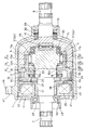
- Sectional drawing which shows the rotation transmission device which concerns on 1st Embodiment of 1st invention.
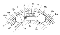
- Sectional view taken along line II-II of FIGS. 1 and 11 An enlarged cross-sectional view of the vicinity of a pair of rollers showing a state in which the roller cage shown in FIG. 2 has moved from the disengagement position to the engagement position.
- Sectional view taken along line IV-IV of FIGS. 1 and 11 Sectional view along the VV line of FIG.
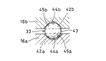
- Sectional view taken along the line VI-VI of FIGS. 1 and 11 Sectional view taken along the line VII-VII of FIG.
- Sectional drawing which shows the rotation transmission device which concerns on embodiment of 2nd invention.
- FIG. 1 shows a rotation transmission device according to a first embodiment of the first invention.
- This rotation transmission device has a cylindrical housing 1 having both ends open, an input shaft 2 arranged so that one end is housed in the housing 1, and a cam surface 3 formed on the outer periphery of the input shaft 2 in the radial direction. It has an outer ring 5 having a cylindrical surface 4 facing the inner circumference.
- an outer ring end plate 7 facing the shaft end 6 of the input shaft 2 in the axial direction is formed seamlessly and integrally with the outer ring 5.
- the outer ring end plate 7 closes one end in the axial direction of the tubular outer ring 5 formed so as to surround the outer diameter side of the accommodating portion of the input shaft 2 in the housing 1.
- an output shaft 8 extending from the outer ring end plate 7 to the side opposite to the side of the input shaft 2 is formed seamlessly and integrally with the outer ring end plate 7.
- the output shaft 8 is arranged side by side on the same straight line as the input shaft 2.
- the input shaft 2 has a spline shaft portion 9 to which rotational torque is input from the outside in a protruding portion from the housing 1.
- the input shaft 2 is seamlessly integrated from the spline shaft portion 9 in the protruding portion of the input shaft 2 from the housing 1 to the cam surface 3 on the outer periphery of the accommodating portion of the input shaft 2 in the housing 1. It is formed as a member.
- the output shaft 8 also has a spline shaft portion 10 that outputs rotational torque transmitted from the outer ring 5 to the outside via the outer ring end plate 7 at a protruding portion from the housing 1.
- This rotation transmission device includes a plurality of rollers 11a and 11b incorporated between the cam surface 3 and the cylindrical surface 4, a roller cage 12 for holding these rollers 11a and 11b, and a holder for moving the roller cage 12. It has an instrument actuator 13.
- a plurality of cam surfaces 3 are provided at equal intervals in the circumferential direction on the outer periphery of the accommodating portion (inner ring 26) of the input shaft 2 in the housing 1.
- the cam surface 3 includes a front cam surface 3a and a rear cam surface 3b arranged behind the input shaft 2 in the normal rotation direction with respect to the front cam surface 3a.
- a cylindrical surface 4 facing the cam surface 3 in the radial direction is provided on the inner circumference of the outer ring 5.
- a pair of rollers 11a and 11b facing each other in the circumferential direction with a roller separation spring 14 sandwiched between the cam surface 3 and the cylindrical surface 4 are incorporated.
- the front roller 11a in the forward rotation direction is incorporated between the front cam surface 3a and the cylindrical surface 4
- the rear roller 11b in the forward rotation direction is the rear cam surface 3b and the cylindrical surface 4. It is built in between.
- the roller release spring 14 presses the rollers 11a and 11b in a direction that widens the distance between the pair of rollers 11a and 11b.
- the front cam surface 3a is formed so that the radial distance from the cylindrical surface 4 gradually decreases from the position of the roller 11a toward the front in the normal rotation direction.
- the rear cam surface 3b is formed so that the radial distance from the cylindrical surface 4 gradually decreases from the position of the roller 11b toward the rear in the normal rotation direction.
- the front cam surface 3a and the rear cam surface 3b are formed so as to be separate planes inclined in opposite directions, but the front cam surface 3a and the rear cam surface 3b are positive on a single plane. It is also possible to form them on the same plane so that the front side portion in the rolling direction is the front cam surface 3a and the rear side portion is the rear cam surface 3b.
- the front cam surface 3a and the rear cam surface 3b can be curved, but if they are flat as shown in FIG. 3, the processing cost can be reduced.
- the roller cage 12 is a first split retainer that supports one of the pair of rollers 11a and 11b facing each other in the circumferential direction with the roller release spring 14 in between. It consists of a 12A and a second split cage 12B that supports the other roller 11b.
- the first split cage 12A and the second split cage 12B are supported so as to be relatively rotatable, and the pair of rollers 11a and 11b are supported so that the distance between the pair of rollers 11a and 11b changes according to the relative rotation. Are individually supported.
- the first split cage 12A has a plurality of pillar portions 15a arranged at intervals in the circumferential direction, and an annular flange portion 16a connecting the ends of these pillar portions 15a.
- the second split cage 12B also has a plurality of pillar portions 15b arranged at intervals in the circumferential direction, and an annular flange portion 16b that connects the ends of these pillar portions 15b to each other.
- the pillar portion 15a of the first split cage 12A and the pillar portion 15b of the second split cage 12B have a pair of rollers 11a and 11b facing each other in the circumferential direction with the roller separation spring 14 in between from both sides in the circumferential direction. It is inserted between the inner circumference of the outer ring 5 and the outer circumference of the input shaft 2 (the portion of the inner ring 26) so as to be sandwiched.
- the flange portion 16b of the second split cage 12B is the first split cage. It is arranged so as to face the inner ring 26 (cam surface 3) in the axial direction with respect to the flange portion 16a of the 12A.
- the flange portion 16b of the second split cage 12B is provided with a plurality of notches 17 at intervals in the circumferential direction in order to avoid interference with the pillar portion 15a of the first split cage 12A. ..
- the inner circumference of the flange portion 16a of the first split cage 12A and the inner circumference of the flange portion 16b of the second split cage 12B are rotatably supported by a cylindrical surface 18 provided on the outer circumference of the input shaft 2. ing.
- the first split cage 12A and the second split cage 12B engage the rollers 11a and 11b between the cylindrical surface 4 and the cam surface 3 by widening the distance between the pair of rollers 11a and 11b.
- Disengagement of the rollers 11a and 11b between the cylindrical surface 4 and the cam surface 3 by narrowing the distance between the engaging position (see FIG. 3) and the pair of rollers 11a and 11b. It can be moved to and from the position (see FIG. 2).
- the flange portion 16a of the first split cage 12A is supported in the axial direction by the annular convex portion 20 provided on the outer periphery of the input shaft 2 via the thrust bearing 19, whereby the movement in the axial direction is restricted. There is.
- the spring holder 21 is fixed at a position (side surface of the inner ring 26) adjacent to the cam surface 3 on the outer circumference of the input shaft 2 in the axial direction.
- the spring holder 21 has a stopper piece 22 located between the pillar portions 15a and 15b facing each other in the circumferential direction with the pair of rollers 11a and 11b sandwiched between them.
- this stopper piece 22 when both pillar portions 15a and 15b move in a direction in which the distance between the pair of rollers 11a and 11b is narrowed, the edges on both sides of the stopper piece 22 receive the pillar portions 15a and 15b.
- roller release spring 14 between the pair of rollers 11a and 11b is prevented from being excessively compressed and damaged, and the inner ring 26 (cam surface 3) when the distance between the pair of rollers 11a and 11b is narrowed. ),
- the positions of the rollers 11a and 11b can be fixed.
- the spring holder 21 has a spring holding piece 23 that holds the roller release spring 14.
- the spring holding piece 23 is integrally formed with the stopper piece 22 so as to extend axially between the inner circumference (cylindrical surface 4) of the outer ring 5 and the outer circumference (cam surface 3) of the inner ring 26.
- the spring holding piece 23 faces the spring support surface 24 (see FIG. 3) formed between the front cam surface 3a and the rear cam surface 3b on the outer periphery of the input shaft 2 (the portion of the inner ring 26) in the radial direction. It is arranged like this.
- a recess 25 for accommodating the roller release spring 14 is formed on the surface of the spring holding piece 23 facing the spring support surface 24.
- the roller release spring 14 is a compression coil spring.
- the spring holding piece 23 regulates the movement of the roller release spring 14 by the recess 25, so that the roller release spring 14 is formed between the inner circumference (cylindrical surface 4) of the outer ring 5 and the outer circumference (cam surface 3) of the inner ring 26. It prevents it from falling off in the axial direction.
- this rotation transmission device places the roller cage 12 (that is, the first split cage 12A and the second split cage 12B) between the cylindrical surface 4 and the cam surface 3 with the roller 11a. Move between the engagement position for engaging 11b (see FIG. 3) and the disengagement position for disengaging the rollers 11a and 11b between the cylindrical surface 4 and the cam surface 3 (see FIG. 2).
- the cage actuator 13 an armature 30 movably supported in the axial direction, a rotor 31 arranged so as to face the armature 30 in the axial direction, and an electromagnet 32 for attracting the armature 30 to the rotor 31 by energization. It has a ball lamp mechanism 33 that converts the operation in which the armature 30 is attracted to the rotor 31 into an operation in which the first split cage 12A and the second split cage 12B move from the engaging position to the disengaging position. ..
- the armature 30 has an annular disk portion 34 and a cylindrical portion 35 integrally formed so as to extend axially from the outer circumference of the disk portion 34.
- a cylindrical portion 36 integrally formed so as to extend axially from the outer circumference of the flange portion 16b of the second split cage 12B is press-fitted into the cylindrical portion 35 of the armature 30, and the armature 30 is pressed into the cylindrical portion 35. It is connected to the second split cage 12B so as to move integrally with the second split cage 12B in the axial direction.
- the armature 30 is supported by a cylindrical surface 37 provided on the annular convex portion 20 on the outer periphery of the input shaft 2 so as to be rotatable and axially movable.
- the armature 30 is supported in the axial direction at two positions separated from each other in the axial direction (that is, the inner circumference of the armature 30 and the inner circumference of the second split cage 12B) so that the armature 30 can be moved in the posture of the armature 30. Is prevented from tilting in the direction perpendicular to the axis.
- the rotor 31 is supported on the outer circumference of the input shaft 2 so as not to move relative to either the axial direction or the circumferential direction by fitting the rotor 31 on the outer circumference of the input shaft 2 with a tightening margin.
- the rotor 31 and the armature 30 are made of a metal having ferromagnetism.
- the electromagnet 32 has a solenoid coil 39 and a field core 40 around which the solenoid coil 39 is wound.
- the field core 40 is inserted into the end of the housing 1 on the input shaft 2 side and is prevented from coming off by a retaining ring 41.
- the electromagnet 32 forms a magnetic path through the field core 40, the rotor 31, and the armature 30, and attracts the armature 30 to the rotor 31.
- the ball lamp mechanism 33 is provided with an inclination of the flange portion 16a of the first split cage 12A on the surface facing the flange portion 16b of the second split cage 12B.
- the groove 42a and the inclined groove 42b provided on the surface of the flange portion 16b of the second split cage 12B facing the flange portion 16a of the first split retainer 12A are incorporated between the inclined groove 42a and the inclined groove 42b. It consists of a ball 43.
- the inclined groove 42a and the inclined groove 42b are formed so as to extend in the circumferential direction, respectively.
- the inclined groove 42a has a shape having a groove bottom 45a inclined so as to gradually become shallower in one direction in the circumferential direction from the deepest portion 44a having the deepest axial depth, and the inclined groove 42b also has an axial direction.
- the shape has a groove bottom 45b that is inclined so as to gradually become shallower in the other direction in the circumferential direction from the deepest portion 44b having the deepest depth.
- the ball 43 is arranged so as to be sandwiched between the groove bottom 45a and the groove bottom 45b.
- the balls 43 move in the inclined grooves 42a, respectively.
- the first split cage 12A and the second split cage 12B rotate relative to each other, and as a result, the pillar portions 15a and the first split cage 12A of the first split cage 12A are rotated.
- the pillar portion 15b of the split cage 12B of 2 operates so as to move in a direction of narrowing the distance between the pair of rollers 11a and 11b.
- the armature 30 is urged away from the rotor 31 by the force of the roller release spring 14. That is, the force with which the roller separation spring 14 shown in FIG. 2 presses the rollers 11a and 11b in the direction of widening the distance between the pair of rollers 11a and 11b is applied to the first split cage 12A and the second split cage 12B. introduce.
- the circumferential force received by the first split cage 12A and the second split cage 12B is axially distant from the rotor 31 by the ball lamp mechanism 33 shown in FIGS. 6 and 7A and 7B. It is converted into force and transmitted to the second split cage 12B.
- the housing 1 includes a large-diameter tubular portion 1a formed in a cylindrical shape for accommodating a cage actuator 13 (armature 30, rotor 31, electromagnet 32, ball lamp mechanism 33) and an outer ring 5. It is composed of a cylindrical small-diameter tubular portion 1b having an inner diameter smaller than the inner diameter of the large-diameter tubular portion 1a, and a connecting portion 1c that connects the large-diameter tubular portion 1a and the small-diameter tubular portion 1b.
- the large-diameter cylinder portion 1a and the small-diameter cylinder portion 1b are arranged so that the large-diameter cylinder portion 1a is located on the input shaft 2 side and the small-diameter cylinder portion 1b is located on the output shaft 8 side.
- the end of the input shaft 2 opposite to the shaft end 6 side protrudes from the large diameter cylinder portion 1a, and the side opposite to the side connected to the outer ring end plate 7 of the output shaft 8 from the small diameter cylinder portion 1b. The end of the is protruding.
- the large-diameter tubular portion 1a faces the outer circumference of the outer ring 5 and the outer ring end plate 7 in the radial direction
- the small-diameter tubular portion 1b faces the outer circumference of the output shaft 8 in the radial direction
- the connecting portion 1c faces the outer ring end. It is in a state of facing the plate 7 in the axial direction.
- the connecting portion 1c is formed so that the inner diameter decreases from the large-diameter tubular portion 1a side toward the small-diameter tubular portion 1b side.
- the large-diameter tubular portion 1a is formed with a fixing flange 46 that projects radially outward from the outer circumference of the large-diameter tubular portion 1a.
- a through hole 47 in the axial direction is formed in the fixing flange 46, and the fixing flange 46 can be fixed to the support member 68 by inserting a bolt 67 into the through hole 47 and tightening the bolt 67. There is.
- the field core 40 is fitted to the inner circumference of the large diameter tubular portion 1a of the housing 1.
- a retaining ring 41 for preventing the field core 40 from coming off is mounted on the inner circumference of the end of the large-diameter tubular portion 1a opposite to the small-diameter tubular portion 1b.
- a bearing fitting cylinder 48 is fixedly provided on the surface of the field core 40 opposite to the side on which the armature 30 is attracted.
- the bearing fitting cylinder 48 may be provided by fixing the bearing fitting cylinder 48 formed separately from the field core 40 to the field core 40 by welding or the like, and the bearing fitting cylinder 48 is jointed with the field core 40. It may be formed integrally without.
- a first radial bearing 49 that rotatably supports the input shaft 2 is incorporated between the inner circumference of the bearing fitting cylinder 48 and the outer circumference of the input shaft 2.
- the first radial bearing 49 is, for example, a deep groove ball bearing.
- a retaining ring 50 for preventing the first radial bearing 49 from coming off is mounted on the inner circumference of the bearing fitting cylinder 48.
- a second radial bearing 51 that rotatably supports the output shaft 8 is incorporated in the inner circumference of the small diameter tubular portion 1b of the housing 1.
- the second radial bearing 51 is, for example, a deep groove ball bearing.
- a cylindrical second bearing fitting surface 52 into which the second radial bearing 51 is fitted is provided on the outer periphery of the output shaft 8.
- the second radial bearing 51 has an outer ring 53 fitted to the inner circumference of the small-diameter tubular portion 1b, an inner ring 54 fitted to the second bearing fitting surface 52, and an interval in the circumferential direction between the outer ring 53 and the inner ring 54. It has a plurality of rolling elements 55 provided therein.
- the second radial bearing 51 is assembled so that the axial end surface of the inner ring 54 contacts the outer ring end plate 7, and the inner peripheral surface of the inner ring 54 contacts the outer periphery of the output shaft 8.
- a bearing fitting surface 56 is formed on the inner circumference of the outer ring 5.
- a cylindrical surface 57 having a diameter smaller than that of the cylindrical surface 4 is formed adjacent to the output shaft 8 with respect to the cylindrical surface 4.
- the third bearing fitting surface 56 and the cylindrical surface 57 of the outer ring 5 are opposed to each other in the radial direction.
- a third bearing 58 that connects the input shaft 2 and the outer ring 5 so as to be relatively rotatable is incorporated between the third bearing fitting surface 56 and the cylindrical surface 57.
- the third bearing 58 is, for example, a deep groove ball bearing.
- a ring plate-shaped washer 59 is mounted on the cam surface 3 side with respect to the third bearing 58.
- the washer 59 is formed to have a diameter larger than that of the cam surface 3 so as to have a portion facing the axial end faces of the rollers 11a and 11b, and by restricting the axial movement of the rollers 11a and 11b, the rollers 11a and 11b can be moved. It prevents the cam surface 3 from protruding in the axial direction.
- a connecting pin 60 that connects the shaft end 6 of the input shaft 2 and the outer ring end plate 7 so as to be relatively rotatable is incorporated.
- the connecting pin 60 is a columnar protrusion seamlessly and integrally formed with the shaft end 6 of the input shaft 2 so as to project from the shaft end 6 of the input shaft 2 toward the outer ring end plate 7.
- a pin accommodating hole 61 for accommodating the connecting pin 60 is formed in the outer ring end plate 7, and the connecting pin 60 is rotatably supported by a rolling bearing 62 press-fitted into the pin accommodating hole 61.
- the pin accommodating hole 61 is a bottomed cylindrical hole having a cylindrical inner circumference.
- the rolling bearing 62 is a needle roller bearing having a plurality of needle rollers 63 arranged at intervals in the circumferential direction and a cage 64 for holding the needle rollers 63.
- the needle-shaped roller 63 has a diameter of 4 mm or less (preferably 3 mm or less), and the length is set in the range of 3 to 10 times the diameter.
- a shell-shaped outer ring 65 On the outer diameter side of the needle-shaped roller 63, a shell-shaped outer ring 65 with which the needle-shaped roller 63 rolls and contacts is mounted.
- the shell-shaped outer ring 65 is a thin outer ring having a thickness of 1 mm or less (preferably 0.8 mm or less), and an inward flange portion 66 that regulates the axial movement range of the needle-shaped rollers 63 at both ends in the axial direction. Is formed.
- the shell-shaped outer ring 65 is inserted into the pin accommodating hole 61 with a tightening allowance.
- the needle-shaped roller 63 is in rolling contact with the outer peripheral surface of the connecting pin 60.
- the inner diameter D 1 of the pin accommodating hole 61 is smaller than the outer diameter d 1 of the second bearing fitting surface 52. Specifically, the inner diameter D 1 of the pin accommodating hole 61 is set to a size of 75% or less (preferably 70% or less) of the outer diameter d 1 of the second bearing fitting surface 52.
- the outer diameter d 2 of the connecting pin 60 is smaller than the outer diameter d 3 of the third bearing fitting surface 56. Specifically, the outer diameter d 2 of the connecting pin 60 is set to a size of 50% or less (preferably 40% or less) of the outer diameter d 3 of the third bearing fitting surface 56.
- the rotation transmission device when the electromagnet 32 is energized, the rotation transmission device is in an disengaged state (idling state) in which rotation transmission between the input shaft 2 and the output shaft 8 is cut off. That is, when the electromagnet 32 is energized, the armature 30 is attracted to the rotor 31, and in conjunction with the operation of the armature 30, the flange portion 16b of the second split cage 12B becomes the flange portion 16a of the first split cage 12A. Move in the axial direction toward. At this time, the ball 43 of the ball lamp mechanism 33 rolls toward the deepest portions 44a, 44b of the inclined grooves 42a, 42b, so that the first split cage 12A and the second split cage 12B rotate relative to each other. ..
- the pillar portion 15a of the first split cage 12A and the pillar portion 15b of the second split cage 12B are paired.
- the rollers 11a and 11b are pressed in the direction in which the distance between the rollers 11a and 11b is narrowed, and as a result, the front roller 11a in the normal rotation direction is in an engagement standby state (the front roller 11a and the cylindrical surface 4 in the normal rotation direction).
- the roller 11a immediately engages between the cylindrical surface 4 and the front cam surface 3a), and the rear side in the normal rotation direction is released.
- the roller 11b is in an engagement standby state (there is a minute gap between the roller 11b on the rear side in the forward rotation direction and the cylindrical surface 4, but when the input shaft 2 rotates in the forward rotation direction, the roller 11b immediately moves to the cylindrical surface 4 and the rear cam. The state of being engaged between the surfaces 3b) is also released. In this state, even if rotation is input to the input shaft 2, the rotation is not transmitted from the input shaft 2 to the outer ring 5, and the input shaft 2 idles.
- the rotation transmission device is in an engaged state in which rotation is transmitted between the input shaft 2 and the output shaft 8. That is, when the energization of the electromagnet 32 is stopped, the armature 30 moves axially in the direction of separation from the rotor 31 by the force of the roller separation spring 14. At this time, due to the force of the roller separation spring 14 that presses the rollers 11a and 11b in the direction in which the distance between the pair of rollers 11a and 11b is widened, the roller 11a on the front side in the forward rotation direction is a cylinder on the inner circumference of the outer ring 5.
- the roller 11b which is engaged between the surface 4 and the front cam surface 3a on the outer circumference of the input shaft 2 and is on the rear side in the normal rotation direction, is formed on the cylindrical surface 4 on the inner circumference of the outer ring 5 and the outer circumference of the input shaft 2. It is in a state of being engaged with the rear cam surface 3b. In this state, when the input shaft 2 rotates in the forward rotation direction, the rotation is transmitted from the input shaft 2 to the outer ring 5 via the roller 11b on the rear side in the forward rotation direction. Further, when the input shaft 2 rotates in the reverse direction, the rotation is transmitted from the input shaft 2 to the outer ring 5 via the roller 11a on the front side in the forward rotation direction.
- the protruding portion of the input shaft 2 from the housing 1 is connected to a drive side shaft (not shown), and the protruding portion of the output shaft 8 from the housing 1 is not shown.
- the fixing flange 46 on the outer periphery of the housing 1 is fixed to a support member 68 (not shown) with bolts 67.
- the rotation transmission device can be used. May act between the input shaft 2 and the output shaft 8 with a radial load in a direction that causes the axis to tilt.
- rollers 11a and 11b are misengaged between the cam surface 3 and the cylindrical surface 4, or the rollers 11a and 11b are excessively strongly engaged between the cam surface 3 and the cylindrical surface 4, so that the rollers 11a and 11b are engaged. It may not be possible to cancel the case).
- the connecting pin 60 that connects the shaft end 6 of the input shaft 2 and the outer ring end plate 7 is a shaft between the shaft end 6 of the input shaft 2 and the outer ring end plate 7. Since the relative movement in the perpendicular direction is prevented, the inclination of the axis line between the input shaft 2 and the output shaft 8 is applied even when a radial load in a direction causing the inclination of the axis line is applied between the input shaft 2 and the output shaft 8. Is unlikely to occur.
- the outer ring formed integrally with the cam surface 3 on the outer periphery of the input shaft 2 and the output shaft 8.
- the distance between the inner circumference of 5 and the cylindrical surface 4 is difficult to change, and the operation of the rollers 11a and 11b incorporated between the outer cam surface 3 of the input shaft 2 and the inner peripheral cylindrical surface 4 of the outer ring 5 is stable. It is possible to make it.
- this rotation transmission device employs, as the connecting pin 60, a columnar protrusion seamlessly formed integrally with the shaft end 6 of the input shaft 2 so as to protrude from the shaft end 6 of the input shaft 2.
- the outer circumference of the connecting pin 60 can be machined at the same time in the step of machining the outer circumference of the input shaft 2. Therefore, it is possible to process the outer circumference of the connecting pin 60 at low cost and in a state where the axis is completely aligned with the input shaft 2.
- the axial thickness of the outer ring end plate 7 can be accommodated by the pin. It is possible to secure the strength of the connecting portion between the outer ring end plate 7 and the output shaft 8 even if the hole 61 is thinned to a thickness as low as or close to the axial depth of the hole 61. Therefore, the axial thickness of the outer ring end plate 7 can be suppressed, and the axial dimension of the rotation transmission device can be suppressed.
- the outer diameter d 2 of the connecting pin 60 is smaller than the outer diameter d 3 of the third bearing fitting surface 56, the inner diameter of the pin accommodating hole 61 accommodating the connecting pin 60 is set. It is possible to set D 1 small. Therefore, the axial thickness of the outer ring end plate 7 can be suppressed, and the axial dimension of the rotation transmission device can be suppressed.
- this rotation transmission device employs a needle roller bearing whose radial thickness is thinner than other bearings (ball bearings, etc.) as the rolling bearing 62, a pin accommodating hole for press-fitting the rolling bearing 62. It is possible to set the inner diameter D 1 of 61 to be small. Therefore, the axial thickness of the outer ring end plate 7 can be suppressed, and the axial dimension of the rotation transmission device can be suppressed.
- the portion of the input shaft 2 protruding from the housing 1 from the spline shaft portion 9 to the cam surface 3 is formed as a seamless integral body. Therefore, for example, the input shaft 2 is housed. It is composed of a main body portion that penetrates in the axial direction from the protruding portion from 1 to the accommodating portion in the housing 1 and an annular member that fits on the outer periphery of the main body portion, and a cam surface 3 is provided on the outer periphery of the annular member. The position accuracy of the cam surface 3 is higher than in the case. Therefore, it is possible to effectively stabilize the operation of the rollers 11a and 11b incorporated between the cam surface 3 and the cylindrical surface 4.
- FIG. 9 shows a second embodiment of the first invention.
- the second embodiment differs from the first embodiment only in the configuration of the connecting pin 60, and the other configurations are the same. Therefore, the parts corresponding to the first embodiment are designated by the same reference numerals, and the description thereof will be omitted.
- a connecting pin 60 for connecting the outer ring end plate 7 and the outer ring end plate 7 so as to be relatively rotatable is incorporated.
- the connecting pin 60 is a columnar member having a constant outer diameter over the entire length in the axial direction.
- the connecting pin 60 is housed in an input shaft side pin accommodating hole 70 formed in the shaft end 6 of the input shaft 2, and the other end of the connecting pin 60 is an outer ring end plate side pin formed in the outer ring end plate 7. It is housed in the storage hole 71.
- the input shaft side pin accommodating hole 70 is a bottomed cylindrical hole having a cylindrical inner circumference.
- the outer ring end plate side pin accommodating hole 71 is also a bottomed cylindrical hole having a cylindrical inner circumference.
- the inner diameter D 2 of the outer ring end plate side pin accommodating hole 71 is smaller than the inner diameter D 3 of the input shaft side pin accommodating hole 70.
- One end side portion of the connecting pin 60 is rotatably supported by a rolling bearing 72 press-fitted into the input shaft side pin accommodating hole 70.
- the third bearing 58 and the rolling bearing 72 are arranged so as to have a portion overlapping in the axial direction.
- the other end of the connecting pin 60 is press-fitted into the outer ring end plate side pin accommodating hole 71. That is, the connecting pin 60 is inserted into the outer ring end plate side pin accommodating hole 71 with a tightening allowance.
- the inner diameter D 2 of the outer ring end plate side pin accommodating hole 71 is smaller than the outer diameter d 1 (see FIG. 8) of the second bearing fitting surface 52.
- the inner diameter D 2 of the outer ring end plate side pin accommodating hole 71 has a size of 65% or less (preferably 55% or less) of the outer diameter d 1 (see FIG. 8) of the second bearing fitting surface 52. Is set to.
- the rolling bearing 72 is a needle roller bearing having a plurality of needle rollers 73 arranged at intervals in the circumferential direction and a cage 74 for holding the needle rollers 73.
- the needle roller 73 has a diameter of 4 mm or less (preferably 3 mm or less), and the length is set in the range of 3 to 10 times the diameter.
- a shell-shaped outer ring 75 with which the needle-shaped roller 73 rolls and contacts is mounted.
- the shell-shaped outer ring 75 is a thin outer ring having a thickness of 1 mm or less (preferably 0.8 mm or less), and an inward flange portion 76 that regulates the axial movement range of the needle-shaped rollers 73 at both ends in the axial direction. Is formed.
- the shell type outer ring 75 is inserted into the input shaft side pin accommodating hole 70 with a tightening allowance.
- a needle-shaped roller 73 is in rolling contact with the outer peripheral surface of the connecting pin 60.
- the connecting pin 60 is press-fitted into the input shaft side pin accommodating hole 70, and the rolling bearing 72 is inserted into the outer ring end plate side pin accommodating hole 71. It is also possible to press-fit.
- the connecting pin 60 is directly press-fitted into the outer ring end plate side pin accommodating hole 71 without using a rolling bearing, so that the outer ring end plate side It is possible to more effectively suppress the inner diameter D 2 of the pin accommodating hole 71. Therefore, the axial thickness of the outer ring end plate 7 can be suppressed, and the axial dimension of the rotation transmission device can be suppressed. Further, since the connecting pin 60 uses a columnar member independent of both the input shaft 2 and the outer ring end plate 7, the connecting pin 60 can be manufactured at low cost.
- this rotation transmission device is arranged so that the third bearing 58 and the rolling bearing 72 have a portion where they overlap in the axial direction, it is possible to effectively suppress the axial length of the rotation transmission device. It has become.
- this rotation transmission device employs a needle roller bearing whose radial thickness is thinner than that of other bearings (ball bearings, etc.) as the rolling bearing 72, the input shaft side into which the rolling bearing 72 is press-fitted is adopted. It is possible to set small the inner diameter D 3 of the pin receiving hole 70. Therefore, the outer diameter of the shaft end 6 of the input shaft 2 can be suppressed, and the radial dimension of the rotation transmission device can be suppressed.
- FIG. 10 shows a third embodiment of the first invention.
- the third embodiment differs from the first embodiment only in the configuration of the connecting pin 60, and the other configurations are the same. Therefore, the parts corresponding to the first embodiment are designated by the same reference numerals, and the description thereof will be omitted.
- a connecting pin 60 for connecting the outer ring end plate 7 and the outer ring end plate 7 so as to be relatively rotatable is incorporated.
- the connecting pin 60 is a columnar member having a constant outer diameter over the entire length in the axial direction.
- the connecting pin 60 is housed in an input shaft side pin accommodating hole 80 formed in the shaft end 6 of the input shaft 2, and the other end of the connecting pin 60 is an outer ring end plate side pin formed in the outer ring end plate 7. It is housed in the storage hole 81.
- the input shaft side pin accommodating hole 80 is a bottomed cylindrical hole having a cylindrical inner circumference.
- the outer ring end plate side pin accommodating hole 81 is also a bottomed cylindrical hole having a cylindrical inner circumference.
- the inner diameter D 4 of the outer ring end plate side pin accommodating hole 81 has the same diameter as the inner diameter D 5 of the input shaft side pin accommodating hole 80.
- One end side portion of the connecting pin 60 is rotatably supported by an input shaft side rolling bearing 82 press-fitted into the input shaft side pin accommodating hole 80.
- the third bearing 58 and the input shaft side rolling bearing 82 are arranged so as to have a portion overlapping in the axial direction.
- the other end side portion of the connecting pin 60 is rotatably supported by the outer ring end plate side rolling bearing 83 press-fitted into the outer ring end plate side pin accommodating hole 81.
- the inner diameter D 4 of the outer ring end plate side pin accommodating hole 81 is smaller than the outer diameter d 1 (see FIG. 8) of the second bearing fitting surface 52.
- the inner diameter D 4 of the outer ring end plate side pin accommodating hole 81 has a size of 65% or less (preferably 55% or less) of the outer diameter d 1 (see FIG. 8) of the second bearing fitting surface 52. Is set to.
- the input shaft side rolling bearing 82 is a needle roller bearing having a plurality of needle rollers 84 arranged at intervals in the circumferential direction and a cage 85 for holding the needle rollers 84.
- the needle-shaped roller 84 has a diameter of 4 mm or less (preferably 3 mm or less), and the length is set in the range of 3 to 10 times the diameter.
- a shell-shaped outer ring 86 with which the needle-shaped rollers 84 roll and contact is mounted on the outer diameter side of the needle-shaped rollers 84.
- the shell-shaped outer ring 86 is a thin outer ring having a thickness of 1 mm or less (preferably 0.8 mm or less), and an inward flange portion 87 that regulates the axial movement range of the needle-shaped rollers 84 at both ends in the axial direction. Is formed.
- the shell type outer ring 86 is inserted into the input shaft side pin accommodating hole 80 with a tightening allowance.
- a needle-shaped roller 84 is in rolling contact with the outer peripheral surface of the connecting pin 60.
- the outer ring end plate side rolling bearing 83 is a needle roller bearing having the same configuration as the input shaft side rolling bearing 82.
- the shaft end 6 of the input shaft 2 and the outer ring end plate 7 are connected by the connecting pin 60 via two rolling bearings, an input shaft side rolling bearing 82 and an outer ring end plate side rolling bearing 83. Therefore, the transmission of rotation via the connecting pin 60 can be prevented extremely effectively. Therefore, it is possible to suppress the rotational torque transmitted from the input shaft 2 to the output shaft 8 via the connecting pin 60 to be extremely small in the idling state in which the transmission of rotation from the input shaft 2 to the output shaft 8 is cut off.
- this rotation transmission device is arranged so that the third bearing 58 and the input shaft side rolling bearing 82 have a portion where they overlap in the axial direction, the axial length of the rotation transmission device can be effectively suppressed. Is possible.
- this rotation transmission device employs a needle roller bearing whose radial thickness is thinner than that of other bearings (ball bearings, etc.) as the input shaft side rolling bearing 82, the input shaft side rolling bearing 82 It is possible to set the inner diameter D 5 of the input shaft side pin accommodating hole 80 for press-fitting to be small. Therefore, the outer diameter of the shaft end 6 of the input shaft 2 can be suppressed, and the radial dimension of the rotation transmission device can be suppressed. Further, as the outer ring end plate side rolling bearing 83, a needle roller bearing having a thinner radial thickness than other bearings (ball bearings, etc.) is adopted, so that the outer ring for press-fitting the outer ring end plate side rolling bearing 83. It is possible to set the inner diameter D 4 of the end plate side pin accommodating hole 81 to be small. Therefore, the axial thickness of the outer ring end plate 7 can be suppressed, and the axial dimension of the rotation transmission device can be suppressed.
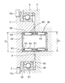
- FIG. 11 shows a rotation transmission device according to an embodiment of the second invention.
- This rotation transmission device is coaxial with the cylindrical housing 1 having both ends open, the input shaft 2 arranged with one end housed in the housing 1, and the input shaft 2 with one end housed in the housing 1.
- the output shafts 8 arranged side by side, the inner ring 26 provided in the housing 1 of the input shaft 2 in the housing 1, and the output shaft 8 into the housing 1 so as to rotate integrally with the output shaft 8.
- An outer ring 5 provided connected to the housing portion, a plurality of rollers 11a and 11b incorporated between the inner circumference of the outer ring 5 and the outer circumference of the inner ring 26, and a roller cage for holding these rollers 11a and 11b. It has a cage 12 and a cage actuator 13 that moves the roller cage 12.
- the input shaft 2 and the inner ring 26 are formed as a seamless integrated member so that both can rotate integrally.
- the input shaft 2 and the inner ring 26 may be formed as separate members, and may be connected by serration fitting or the like so that both of them rotate integrally.
- the input shaft 2 has an input shaft end surface 27 (see FIG. 12) at an end on the side housed in the housing 1.
- the output shaft 8 and the outer ring 5 are also formed as a seamless integrated member so that both can rotate integrally.
- the outer ring 5 is a portion formed in an annular shape surrounding the inner ring 26.
- the outer ring 5 and the output shaft 8 are integrally formed, but the output shaft 8 and the outer ring 5 may be formed as separate members and connected by serration fitting or the like so that both of them rotate integrally.
- the output shaft 8 has an output shaft end surface 28 (see FIG. 12) that faces the input shaft end surface 27 in the axial direction at the end on the side housed in the housing 1.
- a second radial bearing 51 that rotatably supports the output shaft 8 is incorporated in the inner circumference of the small diameter tubular portion 1b of the housing 1.
- the second radial bearing 51 is, for example, a deep groove ball bearing.
- an inward-facing annular protrusion 88 is provided on the inner circumference of the small-diameter tubular portion 1b on the inner circumference of the small-diameter tubular portion 1b on the inner circumference of the small-diameter tubular portion 1b on the inner circumference of the small-diameter tubular portion 1b.
- An elastic member 89 is incorporated between the annular protrusion 88 and the second radial bearing 51.
- the elastic member 89 is incorporated in a state of being compressed in the axial direction, and the output shaft 8 is urged in a direction in which the axial distance between the input shaft end surface 27 and the output shaft end surface 28 is narrowed by the elastic restoring force.
- a disc spring is used as the elastic member 89, but it is also possible to use a compression coil spring or a wave washer instead of the disc spring.
- a cylindrical surface 90 having a diameter smaller than that of the cam surface 3 is formed adjacent to the cam surface 3 on the side of the output shaft 8.
- a cylindrical surface 91 having a diameter smaller than that of the cylindrical surface 4 is formed adjacent to the output shaft 8 with respect to the cylindrical surface 4.
- the cylindrical surface 90 of the inner ring 26 and the cylindrical surface 91 of the outer ring 5 are opposed to each other in the radial direction.
- a third radial bearing 92 that connects the inner ring 26 and the outer ring 5 so as to be relatively rotatable is incorporated between the cylindrical surface 90 and the cylindrical surface 91 (between the radial facing surfaces of the inner ring 26 and the outer ring 5). ..
- the third radial bearing 92 is, for example, a deep groove ball bearing.
- a ring plate-shaped washer 93 is mounted on the cam surface 3 side with respect to the third radial bearing 92.
- the washer 93 is formed to have a diameter larger than that of the cam surface 3 so as to have a portion facing the axial end faces of the rollers 11a and 11b, and by restricting the axial movement of the rollers 11a and 11b, the rollers 11a and 11b can be moved. It prevents the cam surface 3 from protruding in the axial direction.
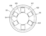
- a plurality of rolling elements 94 sandwiched in the axial direction between the input shaft end surface 27 and the output shaft end surface 28, and an annular cage for holding the plurality of rolling elements 94.
- a thrust bearing 96 having 95 and 95 is incorporated.
- the rolling element 94 is a ball.
- the input shaft end face 27 is an end face of the input shaft side track board 98 fitted into the shaft end recess 97 provided at the end of the input shaft 2, and the output shaft end face 28 is provided at the end of the output shaft 8. This is the end face of the output shaft side track board 100 fitted in the shaft end recess 99.
- the input shaft end surface 27 is formed with a raceway groove 101 having an arcuate cross section with which the rolling elements 94 roll and contact. Further, the output shaft end surface 28 is also formed with a raceway groove 102 having an arcuate cross section with which the rolling elements 94 roll and contact.
- the raceway groove 101 of the input shaft end surface 27 constitutes an input shaft side positioning portion for preventing the positional deviation of the plurality of rolling elements 94 with respect to the input shaft 2, and the raceway groove 102 of the output shaft end surface 28 is formed.
- the output shaft side positioning unit for preventing the positional deviation of the plurality of rolling elements 94 with respect to the output shaft 8 in the radial direction is configured.
- a plurality of rolling elements 94 are arranged side by side on the same circumference at intervals in the circumferential direction.
- a plurality of pockets 103 for accommodating the rolling elements 94 are formed at equal intervals in the circumferential direction.
- the cage 95 holds each rolling element 94 so that the rolling element 94 does not fall out of the pocket 103 even in a state before the thrust bearing 96 is incorporated between the input shaft 2 and the output shaft 8.
- the raceway groove 101 provided on the input shaft end surface 27 prevents the rolling element 94 from being displaced in the radial direction with respect to the input shaft 2, and is provided on the output shaft end surface 28.
- the raceway groove 102 prevents the rolling element 94 from being displaced in the radial direction with respect to the output shaft 8, and as a result, it is possible to prevent the misalignment between the shaft ends of the input shaft 2 and the output shaft 8.
- this rotation transmission device incorporates an elastic member 89 that urges the output shaft 8 in a direction that narrows the axial distance between the input shaft end surface 27 and the output shaft end surface 28, the elastic restoring force of the elastic member 89 causes the rotation transmission device. Preload can be applied to the thrust bearing 96. Therefore, the operation of the rolling element 94 of the thrust bearing 96 is stable.
- the elastic member 89 for urging the output shaft 8 has been described as an example, but the elastic member 89 for urging the input shaft 2 can also be adopted.
- an elastic member 89 is incorporated between the retaining ring 41 and the field core 40 in a state of being compressed in the axial direction, and the elastic member 89 presses the input shaft 2 via the field core 40 and the second radial bearing 51. Therefore, it is also possible to urge the input shaft 2 in a direction that narrows the axial distance between the input shaft end surface 27 and the output shaft end surface 28.
- the input shaft end face 27 may be directly machined on the end of the input shaft 2, and the output shaft end face 28 may be directly machined on the end of the output shaft 8.
- the end face of the input shaft side track board 98 fitted into the shaft end recess 97 formed at the end of the input shaft 2 is adopted, and as the output shaft end face 28, the end face of the output shaft 8 is used.
- the end face of the output shaft side track board 100 fitted in the formed shaft end recess 99 the input shaft end face 27 and the output shaft end face 28 can be machined with low cost and accuracy.
- a ball is used as the rolling element 94 as an example, but as shown in FIGS. 14 and 15, a cylindrical roller may be used as the rolling element 94.
- annular flat surface 104 on which the rolling element 94 rolls and contacts As shown in FIG. 14, on the input shaft end surface 27, an annular flat surface 104 on which the rolling element 94 rolls and contacts, an annular outer brim 105 formed on the outer diameter side of the flat surface 104, and an inner diameter of the flat surface 104.
- An annular inner brim 106 formed on the side is formed.
- the output shaft end surface 28 is also formed on an annular flat surface 107 on which the rolling element 94 rolls and contacts, an annular outer brim 108 formed on the outer diameter side of the flat surface 107, and an inner diameter side of the flat surface 107.
- An annular inner brim 109 is formed.
- the outer brim 105 and the inner brim 106 of the input shaft end surface 27 form an input shaft side positioning portion that prevents the plurality of rolling elements 94 from being displaced in the radial direction with respect to the input shaft 2.
- both the inner brim 106 and the outer brim 105 are provided, but only one of the inner brim 106 and the outer brim 105 may be provided.
- the outer brim 108 and the inner brim 109 of the output shaft end face 28 form an output shaft side positioning portion that prevents the plurality of rolling elements 94 from being displaced in the radial direction with respect to the output shaft 8.
- a plurality of rolling elements 94 are arranged side by side on the same circumference at intervals in the circumferential direction.
- a plurality of pockets 103 for accommodating the rolling elements 94 are formed at equal intervals in the circumferential direction.
- the cage 95 holds each rolling element 94 so that the rolling element 94 does not fall out of the pocket 103 even in a state before the thrust bearing 96 is incorporated between the input shaft 2 and the output shaft 8.
- each component constituting the above rotation transmission device inevitably has an axial dimensional variation (tolerance). Therefore, when the rotation transmission device is assembled, the tolerances of the respective parts are accumulated in the axial direction, so that the contact of the rolling element 94 with the racetracks 98 and 100 of the thrust bearing 96 may become unstable.
- a plurality of types of output shaft-side track boards 100 having different axial thickness dimensions t shown in FIG. 16 are classified into a plurality of groups according to the axial thickness dimension t of the output shaft-side track board 100.
- a track board having an axial thickness dimension that does not cause backlash in the axial direction inside the thrust bearing 96 is selected from a plurality of groups and selected.
- the track board is assembled as the output shaft side track board 100 (track board assembly step).
- the cam surface 3 is used as the outer peripheral engaging surface of the input shaft 2
- the cylindrical surface 4 is used as the inner peripheral engaging surface of the outer ring 5, and the outer peripheral engaging surface (cam).
- the present invention employs a ball as the engaging element. The same can be applied to a rotation transmission device and a rotation transmission device in which both the outer peripheral engaging surface and the inner peripheral engaging surface are cylindrical surfaces and a sprag is used as an engaging element that engages between the cylindrical surfaces. it can.
Landscapes
- Engineering & Computer Science (AREA)
- General Engineering & Computer Science (AREA)
- Mechanical Engineering (AREA)
- Physics & Mathematics (AREA)
- Electromagnetism (AREA)
- Rolling Contact Bearings (AREA)
Abstract
入力軸(2)を回転可能に支持する第1ラジアル軸受(49)と、出力軸(8)を回転可能に支持する第2ラジアル軸受(51)と、入力軸(2)と外輪(5)を相対回転可能に連結する第3軸受(58)とを有する回転伝達装置において、入力軸(2)の軸端(6)と外輪端板(7)とを軸直角方向の相対移動を規制した状態で相対回転可能に連結する連結ピン(60)を設ける。
Description
この発明は、回転の伝達と遮断の切り換えに用いられる回転伝達装置、およびその回転伝達装置の製造方法に関する。
入力軸から出力軸に回転が伝達する状態と、その回転の伝達を遮断する状態とを切り換えるために用いられる回転伝達装置として、例えば、特許文献1、2に記載のものが知られている。
特許文献1に記載の回転伝達装置は、両端が開放した筒状のハウジングと、ハウジングに一端が収容された状態に配置された入力軸と、入力軸の外周のカム面と径方向に対向する円筒面を内周にもつ外輪とを有する。外輪には、入力軸の軸端と軸方向に対向する外輪端板が一体に形成され、外輪端板には、外輪端板から入力軸の側とは反対側に延びる出力軸が一体に形成されている。また、入力軸の外周のカム面と外輪の内周の円筒面との間には一対のローラが組み込まれ、その一対のローラがローラ保持器で保持されている。
ローラ保持器は、相対回転可能に支持された2個の分割保持器からなる。この2個の分割保持器は、前記一対のローラを外輪の内周の円筒面と入力軸の外周のカム面との間に係合させる係合位置と、その各ローラの係合を解除させる係合解除位置との間で移動可能となっている。
また、この回転伝達装置は、2個の分割保持器を係合位置と係合解除位置の間で移動させる保持器アクチュエータとして、軸方向に移動可能に支持されたアーマチュアと、アーマチュアと軸方向に対向して配置されたロータと、通電によりアーマチュアをロータに吸着させる電磁石と、アーマチュアがロータに吸着される動作を、2個の分割保持器が係合位置から係合解除位置に移動する動作に変換するボールランプ機構とを有する。
この回転伝達装置において、入力軸は、入力軸の外周と電磁石の内周との間に組み込まれた第1軸受で回転可能に支持されている。また、出力軸は、出力軸の外周とハウジングの内周との間に組み込まれた第2軸受で回転可能に支持されている。また、入力軸の外周と外輪の内周との間に第3軸受が組み込まれ、その第3軸受によって入力軸と外輪が相対回転可能に連結されている。
ところで、上記の回転伝達装置を自動車に組み付ける場合、入力軸を駆動側シャフトに接続するとともに、出力軸を従動側シャフトに接続し、さらに、回転伝達装置のハウジングを、支持部材にボルト等で固定して使用する。
ここで、回転伝達装置を自動車に組み付ける前においては、入力軸の外周のカム面と外輪の内周の円筒面との間にローラを係合させたり、その係合を解除したりする動作を安定して行なうことができる場合であっても、回転伝達装置を自動車に組み付けた後においては、入力軸の外周のカム面と外輪の内周の円筒面との間にローラを係合させたり、その係合を解除したりする動作が不安定になる可能性があることが分かった。
すなわち、回転伝達装置を自動車に組み付けるときに、回転伝達装置の入力軸を接続する駆動側シャフトの位置と、回転伝達装置の出力軸を接続する従動側シャフトの位置と、回転伝達装置のハウジングを固定する支持部材の位置との相対位置関係により、回転伝達装置には、入力軸と出力軸の間に軸線の傾きを生じさせる方向のラジアル荷重が作用することがある。
そして、このラジアル荷重が原因で、回転伝達装置の入力軸と出力軸の間に、わずかな軸線の傾きが生じる場合がある。このとき、入力軸の外周のカム面と、出力軸と一体に形成された外輪の内周の円筒面との間隔がわずかに変化するため、カム面と円筒面の間に組み込まれたローラの作動が不安定となる可能性(例えば、カム面と円筒面の間隔が本来よりも狭くなることで、カム面と円筒面の間にローラがミス係合したり、カム面と円筒面の間にローラが過度に強く噛み込むことで、ローラの係合を解除することができなくなったりする可能性)があることが分かった。
この発明が解決しようとする課題は、入力軸の外周の外周係合面と外輪の内周の内周係合面との間に組み込まれた係合子が安定して作動する回転伝達装置を提供することである。
上記の課題を解決するため、第1の発明では、以下の構成の回転伝達装置を提供する。
両端が開放した筒状のハウジングと、
前記ハウジングに一端が収容され、前記ハウジング内への収容部分の外周に外周係合面をもつ入力軸と、
前記外周係合面と径方向に対向する内周係合面を内周にもつ外輪と、
前記外輪と一体に形成され、前記入力軸の軸端と軸方向に対向する外輪端板と、
前記外輪端板と一体に形成され、前記外輪端板から前記入力軸の側とは反対側に延びる出力軸と、
前記外周係合面と前記内周係合面の間に組み込まれた係合子と、
前記係合子を前記外周係合面と前記内周係合面の間に係合させる係合位置と、前記係合子の係合を解除させる係合解除位置との間で移動可能に支持された係合子保持器と、
前記係合子保持器を前記係合位置と前記係合解除位置の間で移動させる保持器アクチュエータと、
前記入力軸を回転可能に支持する第1ラジアル軸受と、
前記出力軸を回転可能に支持する第2ラジアル軸受と、
前記入力軸の外周と前記外輪の内周との間に組み込まれ、前記入力軸と前記外輪を相対回転可能に連結する第3軸受とを有する回転伝達装置において、
前記入力軸の軸端と前記外輪端板とを軸直角方向の相対移動を規制した状態で相対回転可能に連結する連結ピンを設けたことを特徴とする回転伝達装置。
両端が開放した筒状のハウジングと、
前記ハウジングに一端が収容され、前記ハウジング内への収容部分の外周に外周係合面をもつ入力軸と、
前記外周係合面と径方向に対向する内周係合面を内周にもつ外輪と、
前記外輪と一体に形成され、前記入力軸の軸端と軸方向に対向する外輪端板と、
前記外輪端板と一体に形成され、前記外輪端板から前記入力軸の側とは反対側に延びる出力軸と、
前記外周係合面と前記内周係合面の間に組み込まれた係合子と、
前記係合子を前記外周係合面と前記内周係合面の間に係合させる係合位置と、前記係合子の係合を解除させる係合解除位置との間で移動可能に支持された係合子保持器と、
前記係合子保持器を前記係合位置と前記係合解除位置の間で移動させる保持器アクチュエータと、
前記入力軸を回転可能に支持する第1ラジアル軸受と、
前記出力軸を回転可能に支持する第2ラジアル軸受と、
前記入力軸の外周と前記外輪の内周との間に組み込まれ、前記入力軸と前記外輪を相対回転可能に連結する第3軸受とを有する回転伝達装置において、
前記入力軸の軸端と前記外輪端板とを軸直角方向の相対移動を規制した状態で相対回転可能に連結する連結ピンを設けたことを特徴とする回転伝達装置。
このようにすると、入力軸の軸端と外輪端板とを連結する連結ピンが、入力軸の軸端と外輪端板との間の軸直角方向の相対移動を防止するので、入力軸と出力軸の間に軸線の傾きを生じさせる方向のラジアル荷重が作用したときにも、入力軸と出力軸の間に軸線の傾きが生じにくい。そのため、入力軸と出力軸の間に軸線の傾きを生じさせる方向のラジアル荷重が作用したときにも、入力軸の外周の外周係合面と、出力軸と一体に形成された外輪の内周の内周係合面との間隔が変化しにくく、入力軸の外周の外周係合面と外輪の内周の内周係合面との間に組み込まれた係合子の作動を安定させることが可能となる。
前記連結ピンとして、前記入力軸の軸端から前記外輪端板に向かって突出するように前記入力軸の軸端と継ぎ目のない一体に形成された円柱状突起を採用し、前記連結ピンを収容するピン収容穴を前記外輪端板に形成し、そのピン収容穴に圧入した転がり軸受で前記連結ピンを回転可能に支持すると好ましい。
このようにすると、連結ピンとして、入力軸の軸端から突出するように入力軸の軸端と継ぎ目のない一体に形成された円柱状突起を採用しているので、連結ピンの外周の加工を、入力軸の外周を加工する工程で同時に行なうことができる。そのため、連結ピンの外周を、低コストで、かつ、入力軸と完全に軸心が一致した状態で加工することが可能となる。
前記出力軸の外周に、前記第2ラジアル軸受が嵌合する円筒状の第2軸受嵌合面が設けられている場合、前記ピン収容穴の内径は、前記第2軸受嵌合面の外径よりも小径とすると好ましい。
このようにすると、ピン収容穴の内径が小さいので、外輪端板の軸方向厚さを、ピン収容穴の軸方向深さと同程度かそれに近い厚さまで薄くしても、外輪端板と出力軸の接続部分の強度を確保することが可能となる。そのため、外輪端板の軸方向厚さを抑えることができ、回転伝達装置の軸方向寸法を抑えることが可能となる。
前記入力軸の外周に、前記第3軸受が嵌合する円筒状の第3軸受嵌合面が設けられている場合、前記連結ピンの外径は、前記第3軸受嵌合面の外径よりも小径とすると好ましい。
このようにすると、連結ピンの外径が小さいので、その連結ピンを収容するピン収容穴の内径を小さく設定することが可能となる。そのため、外輪端板の軸方向厚さを抑えることができ、回転伝達装置の軸方向寸法を抑えることが可能となる。
前記転がり軸受として、針状ころ軸受を採用すると好ましい。
このようにすると、針状ころ軸受は、他の軸受(玉軸受など)に比べて径方向厚さが薄いので、転がり軸受を圧入するピン収容穴の内径を小さく設定することが可能となる。そのため、外輪端板の軸方向厚さを抑えることができ、回転伝達装置の軸方向寸法を抑えることが可能となる。
前記連結ピンとして、一端が前記入力軸の軸端に形成された入力軸側ピン収容穴に収容され、他端が前記外輪端板に形成された外輪端板側ピン収容穴に収容される円柱状部材を採用し、前記連結ピンの一端側部分を、前記入力軸側ピン収容穴に圧入した転がり軸受で回転可能に支持し、前記連結ピンの他端側部分を前記外輪端板側ピン収容穴に圧入すると好ましい。
このようにすると、外輪端板側ピン収容穴には、転がり軸受を介さずに、直接、連結ピンが圧入されているので、外輪端板側ピン収容穴の内径を抑えることができる。そのため、外輪端板の軸方向厚さを抑えることができ、回転伝達装置の軸方向寸法を抑えることが可能となる。また、連結ピンとして、入力軸と外輪端板のいずれからも独立した円柱状部材を採用しているので、連結ピンを低コストで製造することが可能である。
前記第3軸受と前記転がり軸受とは軸方向に重なる部分を有するように配置すると好ましい。
このようにすると、回転伝達装置の軸方向長さを効果的に抑えることが可能となる。
前記出力軸の外周に、前記第2ラジアル軸受が嵌合する円筒状の第2軸受嵌合面が設けられている場合、前記外輪端板側ピン収容穴の内径は、前記第2軸受嵌合面の外径よりも小径とすると好ましい。
このようにすると、外輪端板側ピン収容穴の内径が小さいので、外輪端板の軸方向厚さを、外輪端板側ピン収容穴の軸方向深さと同程度かそれに近い厚さまで薄くしても、外輪端板と出力軸の接続部分の強度を確保することが可能となる。そのため、外輪端板の軸方向厚さを抑えることができ、回転伝達装置の軸方向寸法を抑えることが可能となる。
前記転がり軸受として、針状ころ軸受を採用すると好ましい。
このようにすると、針状ころ軸受は、他の軸受(玉軸受など)に比べて径方向厚さが薄いので、転がり軸受を圧入する入力軸側ピン収容穴の内径を小さく設定することが可能となる。そのため、入力軸の軸端の外径を抑えることができ、回転伝達装置の径方向寸法を抑えることが可能となる。
前記連結ピンとして、一端が前記入力軸の軸端に形成された入力軸側ピン収容穴に収容され、他端が前記外輪端板に形成された外輪端板側ピン収容穴に収容される円柱状部材を採用し、前記連結ピンの一端側部分を、前記入力軸側ピン収容穴に圧入した入力軸側転がり軸受で回転可能に支持し、前記連結ピンの他端側部分を、前記外輪端板側ピン収容穴に圧入した外輪端板側転がり軸受で回転可能に支持することができる。
このようにすると、連結ピンによる入力軸の軸端と外輪端板の連結が、入力軸側転がり軸受と外輪端板側転がり軸受の2つの転がり軸受を介して行なわれるので、連結ピンを介した回転の伝達をきわめて効果的に防止することができる。そのため、入力軸から出力軸への回転の伝達を遮断する空転状態のときに、連結ピンを介して入力軸から出力軸に伝わる回転トルクをきわめて小さく抑えることが可能となる。
前記第3軸受と前記入力軸側転がり軸受とは軸方向に重なる部分を有するように配置すると好ましい。
このようにすると、回転伝達装置の軸方向長さを効果的に抑えることが可能となる。
前記出力軸の外周には、前記第2ラジアル軸受が嵌合する円筒状の第2軸受嵌合面が設けられている場合、前記外輪端板側ピン収容穴の内径は、前記第2軸受嵌合面の外径よりも小径とすると好ましい。
このようにすると、外輪端板側ピン収容穴の内径が小さいので、外輪端板の軸方向厚さを、外輪端板側ピン収容穴の軸方向深さと同程度かそれに近い厚さまで薄くしても、外輪端板と出力軸の接続部分の強度を確保することが可能となる。そのため、外輪端板の軸方向厚さを抑えることができ、回転伝達装置の軸方向寸法を抑えることが可能となる。
前記入力軸側転がり軸受および前記外輪端板側転がり軸受として針状ころ軸受を採用すると好ましい。
このようにすると、針状ころ軸受は、他の軸受(玉軸受など)に比べて径方向厚さが薄いので、入力軸側転がり軸受を圧入する入力軸側ピン収容穴の内径を小さく設定することが可能となる。そのため、入力軸の軸端の外径を抑えることができ、回転伝達装置の径方向寸法を抑えることが可能となる。また、針状ころ軸受は、他の軸受(玉軸受など)に比べて径方向厚さが薄いので、外輪端板側転がり軸受を圧入する外輪端板側ピン収容穴の内径を小さく設定することが可能となる。そのため、外輪端板の軸方向厚さを抑えることができ、回転伝達装置の軸方向寸法を抑えることが可能となる。
前記入力軸は、前記ハウジングからの突出部分から、前記ハウジング内の収容部分の外周の前記外周係合面まで、継ぎ目の無い一体の部材として形成すると好ましい。
このようにすると、入力軸のハウジングからの突出部分から外周係合面までの部分が継ぎ目の無い一体とされているので、例えば、入力軸を、ハウジングからの突出部分からハウジング内への収容部分まで軸方向に貫通する本体部分と、その本体部分の外周に嵌合する環状部材とで構成し、その環状部材の外周に外周係合面を設ける場合と比べて、外周係合面の位置精度を高めることができる。そのため、入力軸の外周の外周係合面と外輪の内周の内周係合面との間に組み込まれた係合子の作動を効果的に安定させることが可能となる。
また、上記の課題を解決するため、第2の発明では、以下の構成の回転伝達装置を提供する。
両端が開放した筒状のハウジングと、
前記ハウジングに一端が収容された状態に配置され、前記ハウジングに収容されている側の端部に入力軸端面をもつ入力軸と、
前記ハウジングに一端が収容された状態で前記入力軸と同軸上に並んで配置され、前記ハウジングに収容されている側の端部に、前記入力軸端面と軸方向に対向する出力軸端面をもつ出力軸と、
前記入力軸と一体に回転するように前記入力軸のハウジング内への収容部分に設けられた内輪と、
前記出力軸と一体に回転するように前記出力軸のハウジング内への収容部分に接続して設けられ、前記内輪を囲む環状に形成された外輪と、
前記外輪の内周と前記内輪の外周との間に組み込まれた係合子と、
前記係合子を前記外輪と前記内輪の間に係合させる係合位置と、前記係合子の係合を解除させる係合解除位置との間で移動可能に支持された係合子保持器と、
前記係合子保持器を前記係合位置と前記係合解除位置の間で移動させる保持器アクチュエータと、
前記入力軸を回転可能に支持する第1ラジアル軸受と、
前記出力軸を回転可能に支持する第2ラジアル軸受と、
前記内輪と前記外輪を相対回転可能に連結する第3ラジアル軸受とを有する回転伝達装置において、
前記入力軸端面と前記出力軸端面の間に軸方向に挟み込まれた複数の転動体と、その複数の転動体を保持する環状の保持器とをもつスラスト軸受を設け、
前記入力軸端面には、前記複数の転動体の前記入力軸に対する径方向の位置ずれを防止する入力軸側位置決め部が設けられ、
前記出力軸端面には、前記複数の転動体の前記出力軸に対する径方向の位置ずれを防止する出力軸側位置決め部が設けられていることを特徴とする回転伝達装置。
両端が開放した筒状のハウジングと、
前記ハウジングに一端が収容された状態に配置され、前記ハウジングに収容されている側の端部に入力軸端面をもつ入力軸と、
前記ハウジングに一端が収容された状態で前記入力軸と同軸上に並んで配置され、前記ハウジングに収容されている側の端部に、前記入力軸端面と軸方向に対向する出力軸端面をもつ出力軸と、
前記入力軸と一体に回転するように前記入力軸のハウジング内への収容部分に設けられた内輪と、
前記出力軸と一体に回転するように前記出力軸のハウジング内への収容部分に接続して設けられ、前記内輪を囲む環状に形成された外輪と、
前記外輪の内周と前記内輪の外周との間に組み込まれた係合子と、
前記係合子を前記外輪と前記内輪の間に係合させる係合位置と、前記係合子の係合を解除させる係合解除位置との間で移動可能に支持された係合子保持器と、
前記係合子保持器を前記係合位置と前記係合解除位置の間で移動させる保持器アクチュエータと、
前記入力軸を回転可能に支持する第1ラジアル軸受と、
前記出力軸を回転可能に支持する第2ラジアル軸受と、
前記内輪と前記外輪を相対回転可能に連結する第3ラジアル軸受とを有する回転伝達装置において、
前記入力軸端面と前記出力軸端面の間に軸方向に挟み込まれた複数の転動体と、その複数の転動体を保持する環状の保持器とをもつスラスト軸受を設け、
前記入力軸端面には、前記複数の転動体の前記入力軸に対する径方向の位置ずれを防止する入力軸側位置決め部が設けられ、
前記出力軸端面には、前記複数の転動体の前記出力軸に対する径方向の位置ずれを防止する出力軸側位置決め部が設けられていることを特徴とする回転伝達装置。
このようにすると、入力軸端面に設けた入力軸側位置決め部によって、入力軸端面と出力軸端面の間に挟み込まれたスラスト軸受の転動体の入力軸に対する径方向の位置ずれが防止され、かつ、出力軸端面に設けた出力軸側位置決め部によって、入力軸端面と出力軸端面の間に挟み込まれたスラスト軸受の転動体の出力軸に対する径方向の位置ずれが防止されるので、その結果として、入力軸と出力軸の軸端同士の位置ずれが防止される。そのため、入力軸と出力軸の間に軸線の傾きを生じさせる方向のラジアル荷重が作用したときにも、入力軸と出力軸の間に軸線の傾きが生じにくくなり、入力軸に設けられた内輪と出力軸に設けられた外輪の間に組み込まれた係合子の作動を安定させることが可能となる。
前記複数の転動体が玉である場合、前記入力軸側位置決め部としては、前記入力軸端面に形成された、前記転動体が転がり接触する断面円弧状の軌道溝を採用することができ、前記出力軸側位置決め部としては、前記出力軸端面に形成された、前記転動体が転がり接触する断面円弧状の軌道溝を採用することができる。
また、前記複数の転動体が円筒ころである場合、前記入力軸側位置決め部としては、前記入力軸端面のうち前記転動体が転がり接触する領域の内径側または外径側に設けられた環状のつばを採用することができ、前記出力軸側位置決め部としては、前記出力軸端面のうち前記転動体が転がり接触する領域の内径側または外径側に設けられた環状のつばを採用することができる。
前記入力軸端面としては、前記入力軸の端部に形成された軸端凹部に嵌め込んだ入力軸側軌道盤の端面を採用し、前記出力軸端面としては、前記出力軸の端部に形成された軸端凹部に嵌め込んだ出力軸側軌道盤の端面を採用すると好ましい。
このようにすると、入力軸の端部を直接加工した入力軸端面や、出力軸の端部を直接加工した出力軸端面を採用する場合よりも、入力軸端面および出力軸端面を低コストで精度よく加工することが可能となる。
前記入力軸端面と前記出力軸端面の軸方向間隔を狭める方向に前記入力軸または前記出力軸を付勢する弾性部材を軸方向に圧縮した状態で組み込むと好ましい。
このようにすると、弾性部材の弾性復元力でスラスト軸受に予圧が付与されるので、スラスト軸受の転動体の動作が安定したものとなる。
また、この発明では、上記の回転伝達装置の製造方法として、以下の構成のものを併せて提供する。
軸方向厚さ寸法が互いに異なる複数種類の軌道盤を、その軌道盤の軸方向厚さ寸法に応じて複数のグループに分類して準備する軌道盤準備工程と、
前記ハウジングに、前記入力軸と前記出力軸と前記内輪と前記外輪と前記係合子と前記係合子保持器と前記保持器アクチュエータと前記第1ラジアル軸受と前記第2ラジアル軸受と前記第3ラジアル軸受と前記スラスト軸受とを組み込んだときに、前記スラスト軸受の内部に軸方向のガタが生じない軸方向厚さ寸法をもつ前記軌道盤を前記複数のグループから選択し、その選択した軌道盤を前記入力軸側軌道盤または前記出力軸側軌道盤として組み付ける軌道盤組み付け工程と、
を有する回転伝達装置の製造方法。
軸方向厚さ寸法が互いに異なる複数種類の軌道盤を、その軌道盤の軸方向厚さ寸法に応じて複数のグループに分類して準備する軌道盤準備工程と、
前記ハウジングに、前記入力軸と前記出力軸と前記内輪と前記外輪と前記係合子と前記係合子保持器と前記保持器アクチュエータと前記第1ラジアル軸受と前記第2ラジアル軸受と前記第3ラジアル軸受と前記スラスト軸受とを組み込んだときに、前記スラスト軸受の内部に軸方向のガタが生じない軸方向厚さ寸法をもつ前記軌道盤を前記複数のグループから選択し、その選択した軌道盤を前記入力軸側軌道盤または前記出力軸側軌道盤として組み付ける軌道盤組み付け工程と、
を有する回転伝達装置の製造方法。
この製造方法で回転伝達装置を製造すると、回転伝達装置を構成する各部品を製造するときに不可避的に生じる軸方向寸法のばらつき(公差)にかかわらず、その公差が軸方向に累積することによる寸法変動に対応した軸方向厚さ寸法をもつ軌道盤を選択して使用することで、スラスト軸受の軌道盤に対する転動体の接触を安定させることが可能となる。
第1の発明の回転伝達装置は、入力軸の軸端と外輪端板とを連結する連結ピンが、入力軸の軸端と外輪端板との間の軸直角方向の相対移動を防止するので、入力軸と出力軸の間に軸線の傾きを生じさせる方向のラジアル荷重が作用したときにも、入力軸と出力軸の間に軸線の傾きが生じにくい。そのため、入力軸と出力軸の間に軸線の傾きを生じさせる方向のラジアル荷重が作用したときにも、入力軸の外周の外周係合面と、出力軸と一体に形成された外輪の内周の内周係合面との間隔が変化しにくく、入力軸の外周の外周係合面と外輪の内周の内周係合面との間に組み込まれた係合子の作動を安定させることが可能である。
第2の発明の回転伝達装置は、入力軸端面に設けた入力軸側位置決め部によって、入力軸端面と出力軸端面の間に挟み込まれたスラスト軸受の転動体の入力軸に対する径方向の位置ずれが防止され、かつ、出力軸端面に設けた出力軸側位置決め部によって、入力軸端面と出力軸端面の間に挟み込まれたスラスト軸受の転動体の出力軸に対する径方向の位置ずれが防止されるので、その結果として、入力軸と出力軸の軸端同士の位置ずれを防止することができる。そのため、入力軸と出力軸の間に軸線の傾きを生じさせる方向のラジアル荷重が作用したときにも、入力軸と出力軸の間に軸線の傾きが生じにくくなり、入力軸に設けられた内輪と出力軸に設けられた外輪の間に組み込まれた係合子の作動を安定させることが可能である。
図1に、第1の発明の第1実施形態にかかる回転伝達装置を示す。この回転伝達装置は、両端が開放した筒状のハウジング1と、ハウジング1に一端が収容された状態に配置された入力軸2と、入力軸2の外周に形成されたカム面3と径方向に対向する円筒面4を内周にもつ外輪5とを有する。
外輪5には、入力軸2の軸端6と軸方向に対向する外輪端板7が、外輪5と継ぎ目の無い一体に形成されている。外輪端板7は、入力軸2のハウジング1内への収容部分の外径側を囲むように形成された筒状の外輪5の軸方向の一方の端部を塞いでいる。外輪端板7には、外輪端板7から入力軸2の側とは反対側に延びる出力軸8が、外輪端板7と継ぎ目の無い一体に形成されている。
出力軸8は、入力軸2と同一直線上に並んで配置されている。入力軸2は、ハウジング1からの突出部分に、外部から回転トルクが入力されるスプライン軸部9を有する。ここで、入力軸2は、入力軸2のハウジング1からの突出部分にあるスプライン軸部9から、入力軸2のハウジング1内への収容部分の外周のカム面3まで、継ぎ目の無い一体の部材として形成されている。出力軸8も、ハウジング1からの突出部分に、外輪5から外輪端板7を介して伝達する回転トルクを外部に出力するスプライン軸部10を有する。
この回転伝達装置は、カム面3と円筒面4の間に組み込まれた複数のローラ11a,11bと、これらのローラ11a,11bを保持するローラ保持器12と、ローラ保持器12を移動させる保持器アクチュエータ13とを有する。
図2、図3に示すように、入力軸2のハウジング1内への収容部分(内輪26)の外周には、周方向に等間隔に複数のカム面3が設けられている。カム面3は、前方カム面3aと、前方カム面3aに対して入力軸2の正転方向後方に配置された後方カム面3bとからなる。外輪5の内周には、カム面3と半径方向に対向する円筒面4が設けられている。
カム面3と円筒面4の間には、ローラ離反ばね14を間に挟んで周方向に対向する一対のローラ11a,11bが組み込まれている。この一対のローラ11a,11bのうち正転方向の前側のローラ11aは前方カム面3aと円筒面4の間に組み込まれ、正転方向の後側のローラ11bは後方カム面3bと円筒面4の間に組み込まれている。ローラ離反ばね14は、一対のローラ11a,11bの間隔を広げる方向に各ローラ11a,11bを押圧している。
前方カム面3aは、円筒面4との間の径方向の距離が、ローラ11aの位置から正転方向前方に向かって次第に小さくなるように形成されている。後方カム面3bは、円筒面4との間の径方向の距離が、ローラ11bの位置から正転方向後方に向かって次第に小さくなるように形成されている。図3では、前方カム面3aと後方カム面3bを、相反する方向に傾斜した別々の平面となるように形成しているが、前方カム面3aと後方カム面3bは、単一平面の正転方向の前側部分が前方カム面3a、後側部分が後方カム面3bとなるように、同一平面上に形成することも可能である。また、前方カム面3aと後方カム面3bは、曲面とすることも可能であるが、図3のように平面とすると加工コストを低減することができる。
図1~図3に示すように、ローラ保持器12は、ローラ離反ばね14を間にして周方向に対向する一対のローラ11a,11bのうち一方のローラ11aを支持する第1の分割保持器12Aと、他方のローラ11bを支持する第2の分割保持器12Bとからなる。第1の分割保持器12Aと第2の分割保持器12Bは相対回転可能に支持されており、その相対回転に応じて一対のローラ11a,11bの間隔が変化するように一対のローラ11a,11bを個別に支持している。
第1の分割保持器12Aは、周方向に間隔をおいて配置された複数の柱部15aと、これらの柱部15aの端部同士を連結する環状のフランジ部16aとを有する。同様に、第2の分割保持器12Bも、周方向に間隔をおいて配置された複数の柱部15bと、これらの柱部15bの端部同士を連結する環状のフランジ部16bとを有する。
第1の分割保持器12Aの柱部15aと第2の分割保持器12Bの柱部15bは、ローラ離反ばね14を間にして周方向に対向する一対のローラ11a,11bを周方向の両側から挟み込むように、外輪5の内周と入力軸2(内輪26の部分)の外周の間に挿入されている。
図1に示すように、第1の分割保持器12Aのフランジ部16aと第2の分割保持器12Bのフランジ部16bは、第2の分割保持器12Bのフランジ部16bが第1の分割保持器12Aのフランジ部16aよりも内輪26(カム面3)に対して軸方向に近い側となる向きで、軸方向に対向して配置されている。そして、第2の分割保持器12Bのフランジ部16bには、第1の分割保持器12Aの柱部15aとの干渉を避けるための切欠き17が周方向に間隔をおいて複数設けられている。
第1の分割保持器12Aのフランジ部16aの内周と第2の分割保持器12Bのフランジ部16bの内周は、入力軸2の外周に設けられた円筒面18でそれぞれ回転可能に支持されている。これにより、第1の分割保持器12Aと第2の分割保持器12Bは、一対のローラ11a,11bの間隔を広げることにより円筒面4とカム面3との間に各ローラ11a,11bを係合させる係合位置(図3参照)と、一対のローラ11a,11bの間隔を狭めることにより円筒面4とカム面3との間への各ローラ11a,11bの係合を解除させる係合解除位置(図2参照)との間で移動可能となっている。第1の分割保持器12Aのフランジ部16aは、スラスト軸受19を介して、入力軸2の外周に設けられた環状凸部20で軸方向に支持され、これにより軸方向の移動が規制されている。
図4に示すように、入力軸2の外周のカム面3と軸方向に隣接する位置(内輪26の側面)に、ばねホルダ21が固定されている。ばねホルダ21は、一対のローラ11a,11bを間に挟んで周方向に対向する両柱部15a,15bの間に位置するストッパ片22を有する。このストッパ片22は、両柱部15a,15bが一対のローラ11a,11bの間隔を狭める方向に移動したときに、ストッパ片22の両側の縁が各柱部15a,15bを受け止める。これにより、一対のローラ11a,11bの間にあるローラ離反ばね14が過度に圧縮して破損するのを防止するとともに、一対のローラ11a,11bの間隔が狭まったときの内輪26(カム面3)に対する各ローラ11a,11bの位置を一定させることが可能となっている。
図5に示すように、ばねホルダ21は、ローラ離反ばね14を保持するばね保持片23を有する。ばね保持片23は、外輪5の内周(円筒面4)と内輪26の外周(カム面3)の間を軸方向に延びるようにストッパ片22と一体に形成されている。ばね保持片23は、入力軸2(内輪26の部分)の外周の前方カム面3aと後方カム面3bとの間に形成されたばね支持面24(図3参照)に対して半径方向に対向するように配置されている。ばね保持片23のばね支持面24に対する対向面には、ローラ離反ばね14を収容する凹部25が形成されている。ローラ離反ばね14は圧縮コイルばねである。このばね保持片23は、ローラ離反ばね14の移動を凹部25で規制することにより、ローラ離反ばね14が外輪5の内周(円筒面4)と内輪26の外周(カム面3)の間から軸方向に脱落するのを防止している。
図1に示すように、この回転伝達装置は、ローラ保持器12(すなわち第1の分割保持器12Aと第2の分割保持器12B)を、円筒面4とカム面3の間にローラ11a,11bを係合させる係合位置(図3参照)と、円筒面4とカム面3の間へのローラ11a,11bの係合を解除させる係合解除位置(図2参照)との間で移動させる保持器アクチュエータ13として、軸方向に移動可能に支持されたアーマチュア30と、アーマチュア30と軸方向に対向して配置されたロータ31と、通電によりアーマチュア30をロータ31に吸着させる電磁石32と、アーマチュア30がロータ31に吸着される動作を、第1の分割保持器12Aおよび第2の分割保持器12Bが係合位置から係合解除位置に移動する動作に変換するボールランプ機構33とを有する。
アーマチュア30は、環状の円盤部34と、円盤部34の外周から軸方向に延びるように一体に形成された円筒部35とを有する。アーマチュア30の円筒部35には、第2の分割保持器12Bのフランジ部16bの外周から軸方向に延びるように一体に形成された円筒部36が圧入され、この圧入により、アーマチュア30は、第2の分割保持器12Bと軸方向に一体に移動するように第2の分割保持器12Bに連結されている。また、アーマチュア30は、入力軸2の外周の環状凸部20に設けられた円筒面37で回転可能かつ軸方向に移動可能に支持されている。ここで、アーマチュア30は、軸方向に離れた2箇所(すなわちアーマチュア30の内周と、第2の分割保持器12Bの内周)において軸方向に移動可能に支持することにより、アーマチュア30の姿勢が軸直角方向に対して傾くのが防止されている。
ロータ31は、締め代をもって入力軸2の外周に嵌合することにより、軸方向と周方向のいずれにも相対移動しないように入力軸2の外周で支持されている。ロータ31およびアーマチュア30は強磁性を有する金属で形成されている。ロータ31のアーマチュア30に対する対向面には、ロータ31を軸方向に貫通するとともに、円周方向に細長く延びる長孔38が周方向に間隔をおいて複数形成されている。
電磁石32は、ソレノイドコイル39と、ソレノイドコイル39が巻回されたフィールドコア40とを有する。フィールドコア40は、ハウジング1の入力軸2側の端部に挿入されて、止め輪41で抜け止めされている。この電磁石32は、ソレノイドコイル39に通電することにより、フィールドコア40とロータ31とアーマチュア30を通る磁路を形成し、アーマチュア30をロータ31に吸着させる。
図6および図7A、図7Bに示すように、ボールランプ機構33は、第1の分割保持器12Aのフランジ部16aの第2の分割保持器12Bのフランジ部16bに対する対向面に設けられた傾斜溝42aと、第2の分割保持器12Bのフランジ部16bの第1の分割保持器12Aのフランジ部16aに対する対向面に設けられた傾斜溝42bと、傾斜溝42aと傾斜溝42bの間に組み込まれたボール43とからなる。傾斜溝42aと傾斜溝42bは、それぞれ周方向に延びるように形成されている。また、傾斜溝42aは、軸方向の深さが最も深い最深部44aから周方向の一方向に向かって次第に浅くなるように傾斜した溝底45aをもつ形状とされ、傾斜溝42bも、軸方向の深さが最も深い最深部44bから周方向の他方向に向かって次第に浅くなるように傾斜した溝底45bをもつ形状とされている。ボール43は溝底45aと溝底45bの間に挟まれるように配置されている。
このボールランプ機構33は、第2の分割保持器12Bのフランジ部16bが、第1の分割保持器12Aのフランジ部16aに向かって軸方向に移動したときに、ボール43が各傾斜溝42a,42bの最深部44a,44bに向けて転がることにより、第1の分割保持器12Aと第2の分割保持器12Bが相対回転し、その結果、第1の分割保持器12Aの柱部15aと第2の分割保持器12Bの柱部15bとが一対のローラ11a,11bの間隔を狭める方向に移動するように動作する。
アーマチュア30は、ローラ離反ばね14の力によって、ロータ31から離れる方向に付勢されている。すなわち、図2に示すローラ離反ばね14が一対のローラ11a,11bの間隔を広げる方向に各ローラ11a,11bを押圧する力が、第1の分割保持器12Aと第2の分割保持器12Bに伝達する。そして、第1の分割保持器12Aと第2の分割保持器12Bが受ける周方向の力は、図6および図7A、図7Bに示すボールランプ機構33によって、ロータ31から遠ざかる方向の軸方向の力に変換されて第2の分割保持器12Bに伝達する。ここで、図1に示すように、アーマチュア30は、第2の分割保持器12Bに固定されているので、結局、アーマチュア30は、ローラ離反ばね14からボールランプ機構33を介して伝達する力によって、ロータ31から離れる方向に付勢された状態となっている。
図1に示すように、ハウジング1は、保持器アクチュエータ13(アーマチュア30とロータ31と電磁石32とボールランプ機構33)と外輪5とを収容する円筒状に形成された大径筒部1aと、大径筒部1aの内径よりも小さい内径をもつ円筒状の小径筒部1bと、大径筒部1aと小径筒部1bとを連結する連結部1cとからなる。大径筒部1aと小径筒部1bは、大径筒部1aが入力軸2側、小径筒部1bが出力軸8側に位置する向きに配置されている。大径筒部1aからは、入力軸2の軸端6の側とは反対側の端部が突出し、小径筒部1bからは、出力軸8の外輪端板7に接続する側とは反対側の端部が突出した状態となっている。また、大径筒部1aは、外輪5および外輪端板7の外周と径方向に対向し、小径筒部1bは、出力軸8の外周と径方向に対向し、連結部1cは、外輪端板7と軸方向に対向した状態となっている。連結部1cは、大径筒部1a側から小径筒部1b側に向かって内径が縮小するように形成されている。
大径筒部1aには、大径筒部1aの外周から径方向外方に突出する固定用フランジ46が形成されている。固定用フランジ46には軸方向の貫通孔47が形成され、この貫通孔47にボルト67を挿入して締め込むことで、固定用フランジ46を支持部材68に固定することができるようになっている。
フィールドコア40は、ハウジング1の大径筒部1aの内周に嵌合している。大径筒部1aの小径筒部1bとは反対側の端部内周には、フィールドコア40を抜け止めする止め輪41が装着されている。フィールドコア40のアーマチュア30を吸着する側とは反対側の面には、軸受嵌合筒48が固定して設けられている。軸受嵌合筒48は、フィールドコア40とは別体に形成した軸受嵌合筒48を溶接等によりフィールドコア40に固定して設けてもよく、軸受嵌合筒48をフィールドコア40と継ぎ目の無い一体に形成してもよい。
軸受嵌合筒48の内周と入力軸2の外周との間には、入力軸2を回転可能に支持する第1ラジアル軸受49が組み込まれている。第1ラジアル軸受49は、例えば深溝玉軸受である。軸受嵌合筒48の内周には、第1ラジアル軸受49を抜け止めする止め輪50が装着されている。
図8に示すように、ハウジング1の小径筒部1bの内周には、出力軸8を回転可能に支持する第2ラジアル軸受51が組み込まれている。第2ラジアル軸受51は、例えば深溝玉軸受である。出力軸8の外周には、第2ラジアル軸受51が嵌合する円筒状の第2軸受嵌合面52が設けられている。第2ラジアル軸受51は、小径筒部1bの内周に嵌合する外輪53と、第2軸受嵌合面52に嵌合する内輪54と、外輪53と内輪54の間に周方向に間隔をおいて設けられた複数の転動体55とを有する。第2ラジアル軸受51は、内輪54の軸方向端面が外輪端板7に接触し、内輪54の内周面が出力軸8の外周に接触するように組み付けられている。
図1に示すように、入力軸2のハウジング1内への収容部分の外周には、カム面3に対して出力軸8の側に隣接してカム面3よりも小径の円筒状の第3軸受嵌合面56が形成されている。外輪5の内周には、円筒面4に対して出力軸8の側に隣接して円筒面4よりも小径の円筒面57が形成されている。ここで、第3軸受嵌合面56と外輪5の円筒面57は、径方向に対向している。そして、第3軸受嵌合面56と円筒面57の間には、入力軸2と外輪5を相対回転可能に連結する第3軸受58が組み込まれている。第3軸受58は、例えば深溝玉軸受である。
また、第3軸受嵌合面56には、第3軸受58に対してカム面3の側に円環板状のワッシャ59が装着されている。ワッシャ59は、ローラ11a,11bの軸方向端面に対向する部分をもつようにカム面3よりも大径に形成され、ローラ11a,11bの軸方向移動を規制することで、ローラ11a,11bがカム面3から軸方向にはみ出るのを防止している。
図8に示すように、入力軸2の軸端6と外輪端板7との間には、入力軸2の軸端6と外輪端板7の軸直角方向の相対移動を規制した状態で、入力軸2の軸端6と外輪端板7とを相対回転可能に連結する連結ピン60が組み込まれている。ここでは、連結ピン60は、入力軸2の軸端6から外輪端板7に向かって突出するように入力軸2の軸端6と継ぎ目のない一体に形成された円柱状突起である。
外輪端板7には、連結ピン60を収容するピン収容穴61が形成され、そのピン収容穴61に圧入した転がり軸受62で連結ピン60が回転可能に支持されている。ピン収容穴61は、円筒状の内周をもつ有底の円筒穴である。転がり軸受62は、周方向に間隔をおいて配置された複数の針状ころ63と、それらの針状ころ63を保持する保持器64とを有する針状ころ軸受である。針状ころ63は、直径が4mm以下(好ましくは3mm以下)であり、長さが直径の3~10倍の範囲に設定されている。針状ころ63の外径側には、針状ころ63が転がり接触するシェル形外輪65が装着されている。シェル形外輪65は、厚さが1mm以下(好ましくは0.8mm以下)の薄肉の外輪であり、軸方向の両端に針状ころ63の軸方向の移動範囲を規制する内向きのフランジ部66が形成されている。シェル形外輪65は、締め代をもってピン収容穴61に挿入されている。連結ピン60の外周面には、針状ころ63が転がり接触している。
ピン収容穴61の内径D1は、第2軸受嵌合面52の外径d1よりも小径である。具体的には、ピン収容穴61の内径D1は、第2軸受嵌合面52の外径d1の75%以下(好ましくは70%以下)の大きさに設定されている。連結ピン60の外径d2は、第3軸受嵌合面56の外径d3よりも小径である。具体的には、連結ピン60の外径d2は、第3軸受嵌合面56の外径d3の50%以下(好ましくは40%以下)の大きさに設定されている。
この回転伝達装置の動作例を説明する。
図1に示すように、電磁石32に通電しているとき、この回転伝達装置は、入力軸2と出力軸8の間での回転伝達が遮断される係合解除状態(空転状態)となる。すなわち、電磁石32に通電すると、アーマチュア30はロータ31に吸着され、このアーマチュア30の動作に連動して、第2の分割保持器12Bのフランジ部16bが第1の分割保持器12Aのフランジ部16aに向かって軸方向に移動する。このとき、ボールランプ機構33のボール43が各傾斜溝42a,42bの最深部44a,44bに向けて転がることにより、第1の分割保持器12Aと第2の分割保持器12Bとが相対回転する。そして、この第1の分割保持器12Aと第2の分割保持器12Bの相対回転により、第1の分割保持器12Aの柱部15aと第2の分割保持器12Bの柱部15bとが、一対のローラ11a,11bの間隔が狭まる方向に各ローラ11a,11bを押圧し、その結果、正転方向の前側のローラ11aの係合待機状態(正転方向の前側のローラ11aと円筒面4の間に微小隙間があるが、入力軸2が逆転方向に回転するとローラ11aが直ちに円筒面4と前方カム面3aの間に係合する状態)が解除されるとともに、正転方向の後側のローラ11bの係合待機状態(正転方向の後側のローラ11bと円筒面4の間に微小隙間があるが、入力軸2が正転方向に回転するとローラ11bが直ちに円筒面4と後方カム面3bの間に係合する状態)も解除された状態となる。この状態で、入力軸2に回転が入力されても、その回転は入力軸2から外輪5に伝達せず、入力軸2は空転する。
一方、電磁石32への通電を停止しているとき、この回転伝達装置は、入力軸2と出力軸8の間で回転が伝達する係合状態となる。すなわち、電磁石32への通電を停止すると、アーマチュア30は、ローラ離反ばね14の力によってロータ31から離反する方向に軸方向移動する。また、このとき、一対のローラ11a,11bの間隔が広がる方向に各ローラ11a,11bを押圧するローラ離反ばね14の力によって、正転方向の前側のローラ11aは、外輪5の内周の円筒面4と入力軸2の外周の前方カム面3aとの間に係合し、かつ、正転方向の後側のローラ11bは、外輪5の内周の円筒面4と入力軸2の外周の後方カム面3bとの間に係合した状態となる。この状態で、入力軸2が正転方向に回転すると、その回転は、正転方向の後側のローラ11bを介して入力軸2から外輪5に伝達する。また、入力軸2が逆転方向に回転すると、その回転は、正転方向の前側のローラ11aを介して入力軸2から外輪5に伝達する。
ところで、上記の回転伝達装置を自動車に組み付ける場合、入力軸2のハウジング1からの突出部分を図示しない駆動側シャフトに接続するとともに、出力軸8のハウジング1からの突出部分を図示しない従動側シャフトに接続し、さらに、ハウジング1の外周の固定用フランジ46を図示しない支持部材68にボルト67で固定する。このとき、入力軸2を接続する駆動側シャフトの位置と、出力軸8を接続する従動側シャフトの位置と、ハウジング1を固定する支持部材68の位置との相対位置関係により、回転伝達装置には、入力軸2と出力軸8の間に軸線の傾きを生じさせる方向のラジアル荷重が作用することがある。
そして、このラジアル荷重が原因で、回転伝達装置の入力軸2と出力軸8の間に、わずかな軸線の傾きが生じる場合がある。このとき、内輪26と外輪5の相対位置がずれ、入力軸2の外周のカム面3と、出力軸8と一体に形成された外輪5の内周の円筒面4との間隔がわずかに変化するため、カム面3と円筒面4の間に組み込まれたローラ11a,11bの作動が不安定となる可能性(例えば、カム面3と円筒面4の間隔が本来よりも狭くなることで、カム面3と円筒面4の間にローラ11a,11bがミス係合したり、カム面3と円筒面4の間にローラ11a,11bが過度に強く噛み込むことで、ローラ11a,11bの係合を解除することができなくなったりする可能性)がある。
この問題に対し、上記の回転伝達装置では、入力軸2の軸端6と外輪端板7とを連結する連結ピン60が、入力軸2の軸端6と外輪端板7との間の軸直角方向の相対移動を防止するので、入力軸2と出力軸8の間に軸線の傾きを生じさせる方向のラジアル荷重が作用したときにも、入力軸2と出力軸8の間に軸線の傾きが生じにくい。そのため、入力軸2と出力軸8の間に軸線の傾きを生じさせる方向のラジアル荷重が作用したときにも、入力軸2の外周のカム面3と、出力軸8と一体に形成された外輪5の内周の円筒面4との間隔が変化しにくく、入力軸2の外周のカム面3と外輪5の内周の円筒面4との間に組み込まれたローラ11a,11bの作動を安定させることが可能である。
また、この回転伝達装置は、連結ピン60として、入力軸2の軸端6から突出するように入力軸2の軸端6と継ぎ目のない一体に形成された円柱状突起を採用しているので、連結ピン60の外周の加工を、入力軸2の外周を加工する工程で同時に行なうことができる。そのため、連結ピン60の外周を、低コストで、かつ、入力軸2と完全に軸心が一致した状態で加工することが可能となっている。
また、この回転伝達装置は、ピン収容穴61の内径D1を、第2軸受嵌合面52の外径d1よりも小径としているので、外輪端板7の軸方向厚さを、ピン収容穴61の軸方向深さと同程度かそれに近い厚さまで薄くしても、外輪端板7と出力軸8の接続部分の強度を確保することが可能である。そのため、外輪端板7の軸方向厚さを抑えることができ、回転伝達装置の軸方向寸法を抑えることが可能となっている。
また、この回転伝達装置は、連結ピン60の外径d2を、第3軸受嵌合面56の外径d3よりも小径としているので、その連結ピン60を収容するピン収容穴61の内径D1を小さく設定することが可能となっている。そのため、外輪端板7の軸方向厚さを抑えることができ、回転伝達装置の軸方向寸法を抑えることが可能である。
また、この回転伝達装置は、転がり軸受62として、他の軸受(玉軸受など)に比べて径方向厚さが薄い針状ころ軸受を採用しているので、転がり軸受62を圧入するピン収容穴61の内径D1を小さく設定することが可能となっている。そのため、外輪端板7の軸方向厚さを抑えることができ、回転伝達装置の軸方向寸法を抑えることが可能である。
また、この回転伝達装置は、入力軸2のハウジング1からの突出部分のスプライン軸部9からカム面3までの部分が継ぎ目の無い一体として形成されているので、例えば、入力軸2を、ハウジング1からの突出部分からハウジング1内への収容部分まで軸方向に貫通する本体部分と、その本体部分の外周に嵌合する環状部材とで構成し、その環状部材の外周にカム面3を設ける場合と比べて、カム面3の位置精度が高い。そのため、カム面3と円筒面4との間に組み込まれたローラ11a,11bの作動を効果的に安定させることが可能である。
図9に、第1の発明の第2実施形態を示す。第2実施形態は、第1実施形態と連結ピン60の構成のみが異なり、他の構成は同じである。そのため、第1実施形態に対応する部分は同一の符号を付して説明を省略する。
入力軸2の軸端6と外輪端板7との間には、入力軸2の軸端6と外輪端板7の軸直角方向の相対移動を規制した状態で、入力軸2の軸端6と外輪端板7とを相対回転可能に連結する連結ピン60が組み込まれている。ここでは、連結ピン60は、軸方向の全長にわたって一定の外径をもつ円柱状部材である。
連結ピン60の一端は、入力軸2の軸端6に形成された入力軸側ピン収容穴70に収容され、連結ピン60の他端は、外輪端板7に形成された外輪端板側ピン収容穴71に収容されている。入力軸側ピン収容穴70は、円筒状の内周をもつ有底の円筒穴である。外輪端板側ピン収容穴71も、円筒状の内周をもつ有底の円筒穴である。外輪端板側ピン収容穴71の内径D2は、入力軸側ピン収容穴70の内径D3よりも小さい。
連結ピン60の一端側部分は、入力軸側ピン収容穴70に圧入した転がり軸受72で回転可能に支持されている。ここで、第3軸受58と転がり軸受72は、軸方向に重なる部分を有するように配置されている。連結ピン60の他端側部分は、外輪端板側ピン収容穴71に圧入されている。すなわち、連結ピン60は、締め代をもって外輪端板側ピン収容穴71に挿入されている。外輪端板側ピン収容穴71の内径D2は、第2軸受嵌合面52の外径d1(図8参照)よりも小径である。具体的には、外輪端板側ピン収容穴71の内径D2は、第2軸受嵌合面52の外径d1(図8参照)の65%以下(好ましくは55%以下)の大きさに設定されている。
転がり軸受72は、周方向に間隔をおいて配置された複数の針状ころ73と、それらの針状ころ73を保持する保持器74とを有する針状ころ軸受である。針状ころ73は、直径が4mm以下(好ましくは3mm以下)であり、長さが直径の3~10倍の範囲に設定されている。針状ころ73の外径側には、針状ころ73が転がり接触するシェル形外輪75が装着されている。シェル形外輪75は、厚さが1mm以下(好ましくは0.8mm以下)の薄肉の外輪であり、軸方向の両端に針状ころ73の軸方向の移動範囲を規制する内向きのフランジ部76が形成されている。シェル形外輪75は、締め代をもって入力軸側ピン収容穴70に挿入されている。連結ピン60の外周面には、針状ころ73が転がり接触している。
ところで、図9に示した構成の入力軸2側と外輪端板7側とを入れ替え、入力軸側ピン収容穴70に連結ピン60を圧入し、外輪端板側ピン収容穴71に転がり軸受72を圧入することも可能である。これに対し、この回転伝達装置では、図9に示すように、外輪端板側ピン収容穴71に、転がり軸受を介さずに、直接、連結ピン60が圧入されているので、外輪端板側ピン収容穴71の内径D2をより効果的に抑えることが可能となっている。そのため、外輪端板7の軸方向厚さを抑えることができ、回転伝達装置の軸方向寸法を抑えることが可能である。また、連結ピン60として、入力軸2と外輪端板7のいずれからも独立した円柱状部材を採用しているので、連結ピン60を低コストで製造することが可能となっている。
また、この回転伝達装置は、第3軸受58と転がり軸受72とが軸方向に重なる部分を有するように配置されているので、回転伝達装置の軸方向長さを効果的に抑えることが可能となっている。
また、この回転伝達装置は、外輪端板側ピン収容穴71の内径D2が、第2軸受嵌合面52の外径d1(図8参照)よりも小径なので、外輪端板7の軸方向厚さを、外輪端板側ピン収容穴71の軸方向深さと同程度かそれに近い厚さまで薄くしても、外輪端板7と出力軸8の接続部分の強度を確保することが可能である。そのため、外輪端板7の軸方向厚さを抑えることができ、回転伝達装置の軸方向寸法を抑えることが可能となっている。
また、この回転伝達装置は、転がり軸受72として、他の軸受(玉軸受など)に比べて径方向厚さが薄い針状ころ軸受を採用しているので、転がり軸受72を圧入する入力軸側ピン収容穴70の内径D3を小さく設定することが可能となっている。そのため、入力軸2の軸端6の外径を抑えることができ、回転伝達装置の径方向寸法を抑えることが可能である。
図10に、第1の発明の第3実施形態を示す。第3実施形態は、第1実施形態と連結ピン60の構成のみが異なり、他の構成は同じである。そのため、第1実施形態に対応する部分は同一の符号を付して説明を省略する。
入力軸2の軸端6と外輪端板7との間には、入力軸2の軸端6と外輪端板7の軸直角方向の相対移動を規制した状態で、入力軸2の軸端6と外輪端板7とを相対回転可能に連結する連結ピン60が組み込まれている。ここでは、連結ピン60は、軸方向の全長にわたって一定の外径をもつ円柱状部材である。
連結ピン60の一端は、入力軸2の軸端6に形成された入力軸側ピン収容穴80に収容され、連結ピン60の他端は、外輪端板7に形成された外輪端板側ピン収容穴81に収容されている。入力軸側ピン収容穴80は、円筒状の内周をもつ有底の円筒穴である。外輪端板側ピン収容穴81も、円筒状の内周をもつ有底の円筒穴である。外輪端板側ピン収容穴81の内径D4は、入力軸側ピン収容穴80の内径D5と同径である。
連結ピン60の一端側部分は、入力軸側ピン収容穴80に圧入した入力軸側転がり軸受82で回転可能に支持されている。ここで、第3軸受58と入力軸側転がり軸受82は、軸方向に重なる部分を有するように配置されている。連結ピン60の他端側部分は、外輪端板側ピン収容穴81に圧入した外輪端板側転がり軸受83で回転可能に支持されている。外輪端板側ピン収容穴81の内径D4は、第2軸受嵌合面52の外径d1(図8参照)よりも小径である。具体的には、外輪端板側ピン収容穴81の内径D4は、第2軸受嵌合面52の外径d1(図8参照)の65%以下(好ましくは55%以下)の大きさに設定されている。
入力軸側転がり軸受82は、周方向に間隔をおいて配置された複数の針状ころ84と、それらの針状ころ84を保持する保持器85とを有する針状ころ軸受である。針状ころ84は、直径が4mm以下(好ましくは3mm以下)であり、長さが直径の3~10倍の範囲に設定されている。針状ころ84の外径側には、針状ころ84が転がり接触するシェル形外輪86が装着されている。シェル形外輪86は、厚さが1mm以下(好ましくは0.8mm以下)の薄肉の外輪であり、軸方向の両端に針状ころ84の軸方向の移動範囲を規制する内向きのフランジ部87が形成されている。シェル形外輪86は、締め代をもって入力軸側ピン収容穴80に挿入されている。連結ピン60の外周面には、針状ころ84が転がり接触している。外輪端板側転がり軸受83は、入力軸側転がり軸受82と同一構成の針状ころ軸受である。
この回転伝達装置は、連結ピン60による入力軸2の軸端6と外輪端板7の連結が、入力軸側転がり軸受82と外輪端板側転がり軸受83の2つの転がり軸受を介して行なわれるので、連結ピン60を介した回転の伝達をきわめて効果的に防止することができる。そのため、入力軸2から出力軸8への回転の伝達を遮断する空転状態のときに、連結ピン60を介して入力軸2から出力軸8に伝わる回転トルクをきわめて小さく抑えることが可能である。
また、この回転伝達装置は、第3軸受58と入力軸側転がり軸受82とが軸方向に重なる部分を有するように配置されているので、回転伝達装置の軸方向長さを効果的に抑えることが可能となっている。
また、この回転伝達装置は、外輪端板側ピン収容穴81の内径D4が、第2軸受嵌合面52の外径d1(図8参照)よりも小径なので、外輪端板7の軸方向厚さを、外輪端板側ピン収容穴81の軸方向深さと同程度かそれに近い厚さまで薄くしても、外輪端板7と出力軸8の接続部分の強度を確保することが可能である。そのため、外輪端板7の軸方向厚さを抑えることができ、回転伝達装置の軸方向寸法を抑えることが可能となっている。
また、この回転伝達装置は、入力軸側転がり軸受82として、他の軸受(玉軸受など)に比べて径方向厚さが薄い針状ころ軸受を採用しているので、入力軸側転がり軸受82を圧入する入力軸側ピン収容穴80の内径D5を小さく設定することが可能である。そのため、入力軸2の軸端6の外径を抑えることができ、回転伝達装置の径方向寸法を抑えることが可能となっている。また、外輪端板側転がり軸受83として、他の軸受(玉軸受など)に比べて径方向厚さが薄い針状ころ軸受を採用しているので、外輪端板側転がり軸受83を圧入する外輪端板側ピン収容穴81の内径D4を小さく設定することが可能である。そのため、外輪端板7の軸方向厚さを抑えることができ、回転伝達装置の軸方向寸法を抑えることが可能となっている。
図11に、第2の発明の実施形態にかかる回転伝達装置を示す。以下、第1の発明の実施形態に対応する部分は同一の符号を付して説明を省略する。この回転伝達装置は、両端が開放した筒状のハウジング1と、ハウジング1に一端が収容された状態に配置された入力軸2と、ハウジング1に一端が収容された状態で入力軸2と同軸上に並んで配置された出力軸8と、入力軸2のハウジング1内への収容部分に設けられた内輪26と、出力軸8と一体に回転するように出力軸8のハウジング1内への収容部分に接続して設けられた外輪5と、外輪5の内周と内輪26の外周との間に組み込まれた複数のローラ11a,11bと、これらのローラ11a,11bを保持するローラ保持器12と、ローラ保持器12を移動させる保持器アクチュエータ13とを有する。
入力軸2と内輪26は、両者が一体に回転するように継ぎ目のない一体の部材として形成されている。入力軸2と内輪26を別部材として形成し、その両者が一体に回転するようにセレーション嵌合等で接続してもよい。入力軸2は、ハウジング1に収容されている側の端部に入力軸端面27(図12参照)を有する。
出力軸8と外輪5も、両者が一体に回転するように継ぎ目のない一体の部材として形成されている。外輪5は、内輪26を囲む環状に形成された部分である。ここでは外輪5と出力軸8を一体に形成しているが、出力軸8と外輪5を別部材として形成し、その両者が一体に回転するようにセレーション嵌合等で接続してもよい。出力軸8は、ハウジング1に収容されている側の端部に、入力軸端面27と軸方向に対向する出力軸端面28(図12参照)を有する。
図12に示すように、ハウジング1の小径筒部1bの内周には、出力軸8を回転可能に支持する第2ラジアル軸受51が組み込まれている。第2ラジアル軸受51は、例えば深溝玉軸受である。また、小径筒部1bの内周には、第2ラジアル軸受51が嵌合する位置に対して大径筒部1a(図11参照)から遠い側に、内向きの環状突起88が設けられ、この環状突起88と第2ラジアル軸受51の間に弾性部材89が組み込まれている。弾性部材89は、軸方向に圧縮した状態で組み込まれ、その弾性復元力によって、入力軸端面27と出力軸端面28の軸方向間隔を狭める方向に出力軸8を付勢している。図では、弾性部材89として、皿ばねを採用した例を示したが、皿ばねに代えて圧縮コイルばねやウェーブワッシャを採用することも可能である。
内輪26の外周には、カム面3に対して出力軸8の側に隣接してカム面3よりも小径の円筒面90が形成されている。外輪5の内周には、円筒面4に対して出力軸8の側に隣接して円筒面4よりも小径の円筒面91が形成されている。ここで、内輪26の円筒面90と外輪5の円筒面91は、径方向に対向している。そして、円筒面90と円筒面91の間(内輪26と外輪5の径方向の対向面間)には、内輪26と外輪5を相対回転可能に連結する第3ラジアル軸受92が組み込まれている。第3ラジアル軸受92は、例えば深溝玉軸受である。
また、内輪26の円筒面90には、第3ラジアル軸受92に対してカム面3の側に円環板状のワッシャ93が装着されている。ワッシャ93は、ローラ11a,11bの軸方向端面に対向する部分をもつようにカム面3よりも大径に形成され、ローラ11a,11bの軸方向移動を規制することで、ローラ11a,11bがカム面3から軸方向にはみ出るのを防止している。
入力軸2と出力軸8の間には、入力軸端面27と出力軸端面28の間に軸方向に挟み込まれた複数の転動体94と、その複数の転動体94を保持する環状の保持器95とを有するスラスト軸受96が組み込まれている。
転動体94は玉である。入力軸端面27は、入力軸2の端部に設けられた軸端凹部97に嵌め込んだ入力軸側軌道盤98の端面であり、出力軸端面28は、出力軸8の端部に設けられた軸端凹部99に嵌め込んだ出力軸側軌道盤100の端面である。
入力軸端面27には、転動体94が転がり接触する断面円弧状の軌道溝101が形成されている。また、出力軸端面28にも、転動体94が転がり接触する断面円弧状の軌道溝102が形成されている。ここで、入力軸端面27の軌道溝101は、複数の転動体94の入力軸2に対する径方向の位置ずれを防止する入力軸側位置決め部を構成し、出力軸端面28の軌道溝102は、複数の転動体94の出力軸8に対する径方向の位置ずれを防止する出力軸側位置決め部を構成している。
図13に示すように、複数の転動体94は、同一円周上に周方向に間隔をおいて並んで配置されている。保持器95には、転動体94を収容する複数のポケット103が周方向に等間隔に形成されている。保持器95は、入力軸2と出力軸8の間にスラスト軸受96を組み込む前の状態においても、転動体94がポケット103から脱落しないように各転動体94を保持している。
ところで、上記の回転伝達装置を自動車に組み付ける場合、入力軸2のハウジング1からの突出部分を図示しない駆動側シャフトに接続するとともに、出力軸8のハウジング1からの突出部分を図示しない従動側シャフトに接続し、さらに、ハウジング1の外周の固定用フランジ46を図示しない支持部材にボルト等で固定する。このとき、入力軸2を接続する駆動側シャフトの位置と、出力軸8を接続する従動側シャフトの位置と、ハウジング1を固定する支持部材の位置との相対位置関係により、回転伝達装置には、入力軸2と出力軸8の間に軸線の傾きを生じさせる方向のラジアル荷重が作用することがある。
そして、このラジアル荷重が原因で、入力軸2と出力軸8の間に軸線の傾きが生じると、内輪26と外輪5の相対位置がずれるため、内輪26と外輪5の間のローラ11a,11bの作動が不安定となる可能性(例えば、外輪5と内輪26の隙間の一部が本来よりも狭くなることで、外輪5と内輪26の間にローラ11a,11bがミス係合したり、外輪5と内輪26の間にローラ11a,11bが過度に強く噛み込むことで、ローラ11a,11bの係合を解除することができなくなったりする可能性)がある。
この問題に対し、上記の回転伝達装置では、入力軸端面27に設けた軌道溝101によって、転動体94の入力軸2に対する径方向の位置ずれが防止され、かつ、出力軸端面28に設けた軌道溝102によって、転動体94の出力軸8に対する径方向の位置ずれが防止されるので、その結果として、入力軸2と出力軸8の軸端同士の位置ずれを防止することができる。そのため、入力軸2と出力軸8の間に軸線の傾きを生じさせる方向のラジアル荷重が作用したときにも、入力軸2と出力軸8の間に軸線の傾きが生じにくくなり、入力軸2に設けられた内輪26と出力軸8に設けられた外輪5の間に組み込まれたローラ11a,11bの作動を安定させることが可能である。
また、この回転伝達装置は、入力軸端面27と出力軸端面28の軸方向間隔を狭める方向に出力軸8を付勢する弾性部材89を組み込んでいるので、その弾性部材89の弾性復元力によってスラスト軸受96に予圧を付与することができる。そのため、スラスト軸受96の転動体94の動作が安定したものとなっている。
上記実施形態では、弾性部材89として出力軸8を付勢するものを例に挙げて説明したが、弾性部材89として、入力軸2を付勢するものを採用することも可能である。例えば、止め輪41とフィールドコア40の間に軸方向に圧縮した状態で弾性部材89を組み込み、その弾性部材89でフィールドコア40と第2ラジアル軸受51とを介して入力軸2を押圧することで、入力軸端面27と出力軸端面28の軸方向間隔を狭める方向に入力軸2を付勢するようにすることも可能である。
図17に示すように、入力軸2の端部に入力軸端面27を直接加工するとともに、出力軸8の端部に出力軸端面28を直接加工してもよいが、上記実施形態のように、入力軸端面27として、入力軸2の端部に形成された軸端凹部97に嵌め込んだ入力軸側軌道盤98の端面を採用し、出力軸端面28として、出力軸8の端部に形成された軸端凹部99に嵌め込んだ出力軸側軌道盤100の端面を採用すると、入力軸端面27および出力軸端面28を低コストで精度よく加工することが可能となる。
上記実施形態では、転動体94として玉を採用したものを例に挙げて説明したが、図14、図15に示すように、転動体94として円筒ころを採用してもよい。
図14に示すように、入力軸端面27には、転動体94が転がり接触する円環状の平面104と、その平面104の外径側に形成された環状の外つば105と、平面104の内径側に形成された環状の内つば106とが形成されている。また、出力軸端面28にも、転動体94が転がり接触する円環状の平面107と、その平面107の外径側に形成された環状の外つば108と、平面107の内径側に形成された環状の内つば109とが形成されている。
ここで、入力軸端面27の外つば105および内つば106は、複数の転動体94の入力軸2に対する径方向の位置ずれを防止する入力軸側位置決め部を構成している。ここでは、内つば106と外つば105の両方を設けたものを示しているが、内つば106と外つば105のうちいずれか一方のみ設けてもよい。同様に、出力軸端面28の外つば108および内つば109は、複数の転動体94の出力軸8に対する径方向の位置ずれを防止する出力軸側位置決め部を構成している。
図15に示すように、複数の転動体94は、同一円周上に周方向に間隔をおいて並んで配置されている。保持器95には、転動体94を収容する複数のポケット103が周方向に等間隔に形成されている。保持器95は、入力軸2と出力軸8の間にスラスト軸受96を組み込む前の状態においても、転動体94がポケット103から脱落しないように各転動体94を保持している。
図14、図15に示すように、スラスト軸受96としてスラストころ軸受を採用すると、大きなラジアル荷重が回転伝達装置に負荷される場合にも、スラスト軸受96の寿命を確保することが可能となる。
ところで、上記の回転伝達装置を構成する各部品には、不可避的に軸方向寸法のばらつき(公差)が存在する。そのため、回転伝達装置を組み立てると、各部品の公差が軸方向に累積するので、スラスト軸受96の各軌道盤98,100に対する転動体94の接触が不安定となるおそれがある。
そこで、以下に説明するように回転伝達装置を製造すると、スラスト軸受96の各軌道盤98,100に対する転動体94の接触を安定させることができる。
まず、図16に示す軸方向厚さ寸法tが互いに異なる複数種類の出力軸側軌道盤100を、その出力軸側軌道盤100の軸方向厚さ寸法tに応じて複数のグループに分類して準備する(軌道盤準備工程)。
次に、図11に示すハウジング1に、入力軸2と出力軸8と内輪26と外輪5とローラ11a,11bとローラ保持器12と保持器アクチュエータ13と第1ラジアル軸受49と第2ラジアル軸受51と第3ラジアル軸受92とスラスト軸受96とを組み込んだときに、スラスト軸受96の内部に軸方向のガタが生じない軸方向厚さ寸法をもつ軌道盤を複数のグループから選択し、その選択した軌道盤を出力軸側軌道盤100として組み付ける(軌道盤組み付け工程)。
このようにして回転伝達装置を製造すると、回転伝達装置を構成する各部品を製造するときに不可避的に生じる軸方向寸法のばらつき(公差)にかかわらず、その公差が軸方向に累積することによる寸法変動に対応した軸方向厚さ寸法をもつ軌道盤を選択して使用することで、スラスト軸受96の軌道盤に対する転動体94の接触を安定させることが可能となる。
ここでは、軸方向厚さ寸法tが互いに異なる複数種類の出力軸側軌道盤100を複数のグループに分類して準備する場合を例に挙げて説明したが、軸方向厚さ寸法が互いに異なる複数種類の入力軸側軌道盤98を複数のグループに分類して準備するようにしてもよい。
上記第1および第2の発明の実施形態では、入力軸2の外周の外周係合面としてカム面3、外輪5の内周の内周係合面として円筒面4、外周係合面(カム面3)と内周係合面(円筒面4)の間に係合する係合子としてローラ11a,11bをそれぞれ採用した例を挙げて説明したが、この発明は、係合子としてボールを採用した回転伝達装置や、外周係合面および内周係合面をいずれも円筒面とし、その両円筒面の間に係合する係合子としてスプラグを採用した回転伝達装置にも同様に適用することができる。
今回開示された実施の形態はすべての点で例示であって制限的なものではないと考えられるべきである。本発明の範囲は上記した説明ではなくて特許請求の範囲によって示され、特許請求の範囲と均等の意味および範囲内でのすべての変更が含まれることが意図される。
1 ハウジング
2 入力軸
3 カム面
4 円筒面
5 外輪
6 軸端
7 外輪端板
8 出力軸
11a,11b ローラ
12 ローラ保持器
13 保持器アクチュエータ
26 内輪
27 入力軸端面
28 出力軸端面
49 第1ラジアル軸受
51 第2ラジアル軸受
52 第2軸受嵌合面
56 第3軸受嵌合面
58 第3軸受
60 連結ピン
61 ピン収容穴
62 転がり軸受
70 入力軸側ピン収容穴
71 外輪端板側ピン収容穴
72 転がり軸受
80 入力軸側ピン収容穴
81 外輪端板側ピン収容穴
82 入力軸側転がり軸受
83 外輪端板側転がり軸受
89 弾性部材
92 第3ラジアル軸受
94 転動体
95 保持器
96 スラスト軸受
97 軸端凹部
98 入力軸側軌道盤
99 軸端凹部
100 出力軸側軌道盤
101 軌道溝
102 軌道溝
104 平面
105 外つば
106 内つば
107 平面
108 外つば
109 内つば
d1 外径
d2 外径
d3 外径
D1 内径
D2 内径
D4 内径
t 軸方向厚さ寸法
2 入力軸
3 カム面
4 円筒面
5 外輪
6 軸端
7 外輪端板
8 出力軸
11a,11b ローラ
12 ローラ保持器
13 保持器アクチュエータ
26 内輪
27 入力軸端面
28 出力軸端面
49 第1ラジアル軸受
51 第2ラジアル軸受
52 第2軸受嵌合面
56 第3軸受嵌合面
58 第3軸受
60 連結ピン
61 ピン収容穴
62 転がり軸受
70 入力軸側ピン収容穴
71 外輪端板側ピン収容穴
72 転がり軸受
80 入力軸側ピン収容穴
81 外輪端板側ピン収容穴
82 入力軸側転がり軸受
83 外輪端板側転がり軸受
89 弾性部材
92 第3ラジアル軸受
94 転動体
95 保持器
96 スラスト軸受
97 軸端凹部
98 入力軸側軌道盤
99 軸端凹部
100 出力軸側軌道盤
101 軌道溝
102 軌道溝
104 平面
105 外つば
106 内つば
107 平面
108 外つば
109 内つば
d1 外径
d2 外径
d3 外径
D1 内径
D2 内径
D4 内径
t 軸方向厚さ寸法
Claims (20)
- 両端が開放した筒状のハウジング(1)と、
前記ハウジング(1)に一端が収容され、前記ハウジング(1)内への収容部分の外周に外周係合面(3)をもつ入力軸(2)と、
前記外周係合面(3)と径方向に対向する内周係合面(4)を内周にもつ外輪(5)と、
前記外輪(5)と一体に形成され、前記入力軸(2)の軸端(6)と軸方向に対向する外輪端板(7)と、
前記外輪端板(7)と一体に形成され、前記外輪端板(7)から前記入力軸(2)の側とは反対側に延びる出力軸(8)と、
前記外周係合面(3)と前記内周係合面(4)の間に組み込まれた係合子(11a,11b)と、
前記係合子(11a,11b)を前記外周係合面(3)と前記内周係合面(4)の間に係合させる係合位置と、前記係合子(11a,11b)の係合を解除させる係合解除位置との間で移動可能に支持された係合子保持器(12)と、
前記係合子保持器(12)を前記係合位置と前記係合解除位置の間で移動させる保持器アクチュエータ(13)と、
前記入力軸(2)を回転可能に支持する第1ラジアル軸受(49)と、
前記出力軸(8)を回転可能に支持する第2ラジアル軸受(51)と、
前記入力軸(2)の外周と前記外輪(5)の内周との間に組み込まれ、前記入力軸(2)と前記外輪(5)を相対回転可能に連結する第3軸受(58)とを有する回転伝達装置において、
前記入力軸(2)の軸端(6)と前記外輪端板(7)とを軸直角方向の相対移動を規制した状態で相対回転可能に連結する連結ピン(60)を設けたことを特徴とする回転伝達装置。 - 前記連結ピン(60)は、前記入力軸(2)の軸端(6)から前記外輪端板(7)に向かって突出するように前記入力軸(2)の軸端(6)と継ぎ目のない一体に形成された円柱状突起であり、
前記連結ピン(60)を収容するピン収容穴(61)が前記外輪端板(7)に形成され、そのピン収容穴(61)に圧入した転がり軸受(62)で前記連結ピン(60)が回転可能に支持されている請求項1に記載の回転伝達装置。 - 前記出力軸(8)の外周には、前記第2ラジアル軸受(51)が嵌合する円筒状の第2軸受嵌合面(52)が設けられ、
前記ピン収容穴(61)の内径(D1)が、前記第2軸受嵌合面(52)の外径(d1)よりも小径とされている請求項2に記載の回転伝達装置。 - 前記入力軸(2)の外周には、前記第3軸受(58)が嵌合する円筒状の第3軸受嵌合面(56)が設けられ、
前記連結ピン(60)の外径(d2)が、前記第3軸受嵌合面(56)の外径(d3)よりも小径とされている請求項2または3に記載の回転伝達装置。 - 前記転がり軸受(62)として、針状ころ軸受を採用した請求項2から4のいずれかに記載の回転伝達装置。
- 前記連結ピン(60)は、一端が前記入力軸(2)の軸端(6)に形成された入力軸側ピン収容穴(70)に収容され、他端が前記外輪端板(7)に形成された外輪端板側ピン収容穴(71)に収容される円柱状部材であり、
前記連結ピン(60)の一端側部分が、前記入力軸側ピン収容穴(70)に圧入した転がり軸受(72)で回転可能に支持され、前記連結ピン(60)の他端側部分が前記外輪端板側ピン収容穴(71)に圧入されている請求項1に記載の回転伝達装置。 - 前記第3軸受(58)と前記転がり軸受(72)とが軸方向に重なる部分を有するように配置されている請求項6に記載の回転伝達装置。
- 前記出力軸(8)の外周には、前記第2ラジアル軸受(51)が嵌合する円筒状の第2軸受嵌合面(52)が設けられ、
前記外輪端板側ピン収容穴(71)の内径(D2)が、前記第2軸受嵌合面(52)の外径(d1)よりも小径とされている請求項6または7に記載の回転伝達装置。 - 前記転がり軸受(72)として、針状ころ軸受を採用した請求項6から8のいずれかに記載の回転伝達装置。
- 前記連結ピン(60)は、一端が前記入力軸(2)の軸端(6)に形成された入力軸側ピン収容穴(80)に収容され、他端が前記外輪端板(7)に形成された外輪端板側ピン収容穴(81)に収容される円柱状部材であり、
前記連結ピン(60)の一端側部分が、前記入力軸側ピン収容穴(80)に圧入した入力軸側転がり軸受(82)で回転可能に支持され、前記連結ピン(60)の他端側部分が、前記外輪端板側ピン収容穴(81)に圧入した外輪端板側転がり軸受(83)で回転可能に支持されている請求項1に記載の回転伝達装置。 - 前記第3軸受(58)と前記入力軸側転がり軸受(82)とが軸方向に重なる部分を有するように配置されている請求項10に記載の回転伝達装置。
- 前記出力軸(8)の外周には、前記第2ラジアル軸受(51)が嵌合する円筒状の第2軸受嵌合面(52)が設けられ、
前記外輪端板側ピン収容穴(81)の内径(D4)が、前記第2軸受嵌合面(52)の外径(d1)よりも小径とされている請求項10または11に記載の回転伝達装置。 - 前記入力軸側転がり軸受(82)および前記外輪端板側転がり軸受(83)として針状ころ軸受を採用した請求項10から12のいずれかに記載の回転伝達装置。
- 前記入力軸(2)は、前記ハウジング(1)からの突出部分から、前記ハウジング(1)内の収容部分の外周の前記外周係合面(3)まで、継ぎ目の無い一体の部材として形成されている請求項1から13のいずれかに記載の回転伝達装置。
- 両端が開放した筒状のハウジング(1)と、
前記ハウジング(1)に一端が収容された状態に配置され、前記ハウジング(1)に収容されている側の端部に入力軸端面(27)をもつ入力軸(2)と、
前記ハウジング(1)に一端が収容された状態で前記入力軸(2)と同軸上に並んで配置され、前記ハウジング(1)に収容されている側の端部に、前記入力軸端面(27)と軸方向に対向する出力軸端面(28)をもつ出力軸(8)と、
前記入力軸(2)と一体に回転するように前記入力軸(2)のハウジング(1)内への収容部分に設けられた内輪(26)と、
前記出力軸(8)と一体に回転するように前記出力軸(8)のハウジング(1)内への収容部分に接続して設けられ、前記内輪(26)を囲む環状に形成された外輪(5)と、
前記外輪(5)の内周と前記内輪(26)の外周との間に組み込まれた係合子(11a,11b)と、
前記係合子(11a,11b)を前記外輪(5)と前記内輪(26)の間に係合させる係合位置と、前記係合子(11a,11b)の係合を解除させる係合解除位置との間で移動可能に支持された係合子保持器(12)と、
前記係合子保持器(12)を前記係合位置と前記係合解除位置の間で移動させる保持器アクチュエータ(13)と、
前記入力軸(2)を回転可能に支持する第1ラジアル軸受(49)と、
前記出力軸(8)を回転可能に支持する第2ラジアル軸受(51)と、
前記内輪(26)と前記外輪(5)を相対回転可能に連結する第3ラジアル軸受(92)とを有する回転伝達装置において、
前記入力軸端面(27)と前記出力軸端面(28)の間に軸方向に挟み込まれた複数の転動体(94)と、その複数の転動体(94)を保持する環状の保持器(95)とをもつスラスト軸受(96)を設け、
前記入力軸端面(27)には、前記複数の転動体(94)の前記入力軸(2)に対する径方向の位置ずれを防止する入力軸側位置決め部が設けられ、
前記出力軸端面(28)には、前記複数の転動体(94)の前記出力軸(8)に対する径方向の位置ずれを防止する出力軸側位置決め部が設けられていることを特徴とする回転伝達装置。 - 前記複数の転動体(94)は玉であり、
前記入力軸側位置決め部は、前記入力軸端面(27)に形成された、前記転動体(94)が転がり接触する断面円弧状の軌道溝(101)であり、
前記出力軸側位置決め部は、前記出力軸端面(28)に形成された、前記転動体(94)が転がり接触する断面円弧状の軌道溝(102)である請求項15に記載の回転伝達装置。 - 前記複数の転動体(94)は円筒ころであり、
前記入力軸側位置決め部は、前記入力軸端面(27)のうち前記転動体(94)が転がり接触する領域の内径側または外径側に設けられた環状のつば(105,106)であり、
前記出力軸側位置決め部は、前記出力軸端面(28)のうち前記転動体(94)が転がり接触する領域の内径側または外径側に設けられた環状のつば(108,109)である請求項15に記載の回転伝達装置。 - 前記入力軸端面(27)は、前記入力軸(2)の端部に設けられた軸端凹部(97)に嵌め込んだ入力軸側軌道盤(98)の端面であり、
前記出力軸端面(28)は、前記出力軸(8)の端部に設けられた軸端凹部(99)に嵌め込んだ出力軸側軌道盤(100)の端面である請求項15から17のいずれかに記載の回転伝達装置。 - 前記入力軸端面(27)と前記出力軸端面(28)の軸方向間隔を狭める方向に前記入力軸(2)または前記出力軸(8)を付勢する弾性部材(89)を軸方向に圧縮した状態で組み込んだ請求項15から18のいずれかに記載の回転伝達装置。
- 請求項18に記載の回転伝達装置の製造方法であって、
軸方向厚さ寸法(t)が互いに異なる複数種類の軌道盤を、その軌道盤の軸方向厚さ寸法(t)に応じて複数のグループに分類して準備する軌道盤準備工程と、
前記ハウジング(1)に、前記入力軸(2)と前記出力軸(8)と前記内輪(26)と前記外輪(5)と前記係合子(11a,11b)と前記係合子保持器(12)と前記保持器アクチュエータ(13)と前記第1ラジアル軸受(49)と前記第2ラジアル軸受(51)と前記第3ラジアル軸受(92)と前記スラスト軸受(96)とを組み込んだときに、前記スラスト軸受(96)の内部に軸方向のガタが生じない軸方向厚さ寸法(t)をもつ前記軌道盤を前記複数のグループから選択し、その選択した軌道盤を前記入力軸側軌道盤(98)または前記出力軸側軌道盤(100)として組み付ける軌道盤組み付け工程と、
を有する回転伝達装置の製造方法。
Applications Claiming Priority (4)
| Application Number | Priority Date | Filing Date | Title |
|---|---|---|---|
| JP2019-116248 | 2019-06-24 | ||
| JP2019116248A JP2021001674A (ja) | 2019-06-24 | 2019-06-24 | 回転伝達装置、および回転伝達装置の製造方法 |
| JP2019123817A JP2021008937A (ja) | 2019-07-02 | 2019-07-02 | 回転伝達装置 |
| JP2019-123817 | 2019-07-02 |
Publications (1)
| Publication Number | Publication Date |
|---|---|
| WO2020262191A1 true WO2020262191A1 (ja) | 2020-12-30 |
Family
ID=74059736
Family Applications (1)
| Application Number | Title | Priority Date | Filing Date |
|---|---|---|---|
| PCT/JP2020/023981 Ceased WO2020262191A1 (ja) | 2019-06-24 | 2020-06-18 | 回転伝達装置、および回転伝達装置の製造方法 |
Country Status (1)
| Country | Link |
|---|---|
| WO (1) | WO2020262191A1 (ja) |
Citations (4)
| Publication number | Priority date | Publication date | Assignee | Title |
|---|---|---|---|---|
| JP2014201269A (ja) * | 2013-04-09 | 2014-10-27 | 本田技研工業株式会社 | 車両用操舵装置 |
| JP2014205474A (ja) * | 2013-04-16 | 2014-10-30 | 本田技研工業株式会社 | 車両用操舵装置 |
| JP2015187472A (ja) * | 2014-03-27 | 2015-10-29 | Ntn株式会社 | 回転伝達装置 |
| JP2019011818A (ja) * | 2017-06-30 | 2019-01-24 | Ntn株式会社 | 回転伝達装置 |
-
2020
- 2020-06-18 WO PCT/JP2020/023981 patent/WO2020262191A1/ja not_active Ceased
Patent Citations (4)
| Publication number | Priority date | Publication date | Assignee | Title |
|---|---|---|---|---|
| JP2014201269A (ja) * | 2013-04-09 | 2014-10-27 | 本田技研工業株式会社 | 車両用操舵装置 |
| JP2014205474A (ja) * | 2013-04-16 | 2014-10-30 | 本田技研工業株式会社 | 車両用操舵装置 |
| JP2015187472A (ja) * | 2014-03-27 | 2015-10-29 | Ntn株式会社 | 回転伝達装置 |
| JP2019011818A (ja) * | 2017-06-30 | 2019-01-24 | Ntn株式会社 | 回転伝達装置 |
Similar Documents
| Publication | Publication Date | Title |
|---|---|---|
| JP6352015B2 (ja) | 回転伝達装置 | |
| WO2021010419A1 (ja) | 回転伝達装置および車両用操舵装置 | |
| JP2009293759A (ja) | 回転伝達装置 | |
| JP2024102289A (ja) | 逆入力遮断クラッチ | |
| JP6121119B2 (ja) | 回転伝達装置 | |
| JP2007016987A (ja) | 逆入力防止クラッチ | |
| JP6251063B2 (ja) | 回転伝達装置 | |
| US20210071722A1 (en) | Rotation transmission device | |
| JP2021001674A (ja) | 回転伝達装置、および回転伝達装置の製造方法 | |
| JP6453014B2 (ja) | 回転伝達装置、およびステアバイワイヤ方式の車両用操舵装置 | |
| JP2021008937A (ja) | 回転伝達装置 | |
| US9976608B2 (en) | Rotation transmission device | |
| JP6732488B2 (ja) | 回転伝達装置 | |
| JP6385104B2 (ja) | 回転伝達装置 | |
| JP2018035816A (ja) | 回転伝達装置 | |
| JP6163385B2 (ja) | 回転伝達装置 | |
| JP2018048744A (ja) | アーマチュアとロータの吸着構造 | |
| JP2013087811A (ja) | 回転伝達装置 | |
| JP4606921B2 (ja) | 回転伝達装置 | |
| JP2002195306A (ja) | クラッチ装置 | |
| JP4912541B2 (ja) | ピニオン軸固定構造 | |
| JP6468773B2 (ja) | 回転伝達装置 | |
| JP6218465B2 (ja) | 回転伝達装置 | |
| JP2013002465A (ja) | 回転軸装置における転がり軸受の取付け構造 | |
| JP2019011868A (ja) | 電磁石によるアーマチュアの吸着構造 |
Legal Events
| Date | Code | Title | Description |
|---|---|---|---|
| 121 | Ep: the epo has been informed by wipo that ep was designated in this application |
Ref document number: 20831080 Country of ref document: EP Kind code of ref document: A1 |
|
| NENP | Non-entry into the national phase |
Ref country code: DE |
|
| 122 | Ep: pct application non-entry in european phase |
Ref document number: 20831080 Country of ref document: EP Kind code of ref document: A1 |