WO2020262095A1 - ステレオ画像処理装置及びステレオ画像処理方法 - Google Patents
ステレオ画像処理装置及びステレオ画像処理方法 Download PDFInfo
- Publication number
- WO2020262095A1 WO2020262095A1 PCT/JP2020/023518 JP2020023518W WO2020262095A1 WO 2020262095 A1 WO2020262095 A1 WO 2020262095A1 JP 2020023518 W JP2020023518 W JP 2020023518W WO 2020262095 A1 WO2020262095 A1 WO 2020262095A1
- Authority
- WO
- WIPO (PCT)
- Prior art keywords
- parallax
- region
- image
- evaluation
- evaluation value
- Prior art date
- Legal status (The legal status is an assumption and is not a legal conclusion. Google has not performed a legal analysis and makes no representation as to the accuracy of the status listed.)
- Ceased
Links
Images

Classifications
-
- H—ELECTRICITY
- H04—ELECTRIC COMMUNICATION TECHNIQUE
- H04N—PICTORIAL COMMUNICATION, e.g. TELEVISION
- H04N13/00—Stereoscopic video systems; Multi-view video systems; Details thereof
- H04N13/20—Image signal generators
- H04N13/204—Image signal generators using stereoscopic image cameras
- H04N13/239—Image signal generators using stereoscopic image cameras using two two-dimensional [2D] image sensors having a relative position equal to or related to the interocular distance
-
- G—PHYSICS
- G06—COMPUTING OR CALCULATING; COUNTING
- G06T—IMAGE DATA PROCESSING OR GENERATION, IN GENERAL
- G06T7/00—Image analysis
- G06T7/50—Depth or shape recovery
- G06T7/55—Depth or shape recovery from multiple images
- G06T7/593—Depth or shape recovery from multiple images from stereo images
-
- G—PHYSICS
- G08—SIGNALLING
- G08G—TRAFFIC CONTROL SYSTEMS
- G08G1/00—Traffic control systems for road vehicles
- G08G1/16—Anti-collision systems
-
- H—ELECTRICITY
- H04—ELECTRIC COMMUNICATION TECHNIQUE
- H04N—PICTORIAL COMMUNICATION, e.g. TELEVISION
- H04N13/00—Stereoscopic video systems; Multi-view video systems; Details thereof
- H04N13/10—Processing, recording or transmission of stereoscopic or multi-view image signals
- H04N13/106—Processing image signals
- H04N13/172—Processing image signals image signals comprising non-image signal components, e.g. headers or format information
- H04N13/178—Metadata, e.g. disparity information
-
- H—ELECTRICITY
- H04—ELECTRIC COMMUNICATION TECHNIQUE
- H04N—PICTORIAL COMMUNICATION, e.g. TELEVISION
- H04N13/00—Stereoscopic video systems; Multi-view video systems; Details thereof
- H04N13/20—Image signal generators
- H04N13/204—Image signal generators using stereoscopic image cameras
- H04N13/243—Image signal generators using stereoscopic image cameras using three or more two-dimensional [2D] image sensors
Definitions
- the present invention relates to a stereo image processing device and a stereo image processing method for calculating a parallax from images taken by a plurality of cameras.
- Stereo cameras are particularly in high demand because they can obtain a wealth of information such as the shape and shading of an object obtained from a captured image and the distance of an object obtained from parallax information from an automobile.
- this stereo camera In order to expand the application of this stereo camera and apply it to autonomous driving, it is necessary to use a camera with higher resolution than before.
- the calculation cost required to calculate the parallax of a stereo camera is very high, and even if a high-resolution camera is simply used, if the conventional image processing is applied as it is, it is within the time required for control of AEB or the like.
- Patent Document 1 first extracts a necessary region from the parallax calculated using a plurality of low-resolution images, and then calculates an accurate parallax for the required region using a plurality of high-resolution images. Is described.
- An object of the present invention is a stereo image capable of calculating highly reliable disparity information by improving the validity of region selection when calculating disparity information at a higher resolution than other parts of a part of a high-resolution captured image. It is an object of the present invention to provide a processing apparatus and a stereo image processing method.
- the present invention is a stereo image processing device that calculates the distance between a car and an obstacle in the outside world of the car, and the outside world of the car is continuously photographed by a plurality of cameras.
- the photographed image memory for storing the photographed image, the area evaluation unit for determining the evaluation value for each area on the photographed image based on at least one of the steering angle information and the vehicle speed information of the vehicle, and the plurality of cameras respectively.
- the parallax calculation is performed with high pixels in the region where the evaluation value determined by the region evaluation unit is relatively high, and low in the region where the evaluation value determined by the region evaluation unit is relatively low. It is provided with a parallax calculation unit that calculates parallax with pixels.
- the present invention when calculating parallax information at a higher resolution than other parts of a part of a high-resolution captured image, it is possible to calculate highly reliable parallax information by improving the validity of region selection. it can.
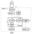
- Block diagram of a stereo image processing apparatus Explanatory drawing of calculation method by 1st evaluation part about evaluation value for each area on photographed image
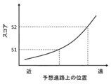
- Schematic diagram of an example of reference data used in the first evaluation section A diagram schematically showing an example of an estimated parallax image calculated by the second evaluation unit.
- Schematic diagram of an example of reference data used in the second evaluation section A flowchart showing the procedure for determining the evaluation value for each region regarding the parallax calculation density in the evaluation value determination unit.
- FIG. 1 is a block diagram of a stereo image processing apparatus according to an embodiment of the present invention.
- the stereo image processing device shown in the figure is a unit in which a camera unit 10 and an image processing unit 20 are combined, and is attached to, for example, the back side (front facing surface) of a rearview mirror in the driver's cab of an automobile.
- This stereo image processing device calculates and outputs the distance between the own vehicle and an obstacle in the outside world (for example, in front of the own vehicle).
- the "own vehicle” is a vehicle equipped with the stereo image processing device described below.
- the camera unit 10 includes a plurality of cameras.
- the camera unit 10 is composed of two cameras attached to the stereo image processing device side by side.
- This amount of deviation is the parallax, and by calculating this parallax, the distance from the own vehicle to the target object can be measured because the positional relationship between the two cameras is known.
- the camera unit 10 may include three or more cameras. Further, although the configuration in which the camera unit 10 captures the front region of the own vehicle will be described by way of example, the configuration may be such that the left region, the right region, or the rear region is captured. The parallax of the images captured by the two cameras in the present embodiment is generated only in the left-right direction, and the parallax is not generated in the vertical direction.
- the image processing unit 20 is a computer configured to include an interface, a CPU, RAM, ROM, memory, and a timer.
- the image processing unit 20 includes elements such as an image acquisition unit 21, a captured image memory 22, a vehicle information acquisition unit 23, a past parallax image acquisition unit 24, an area evaluation unit 25, a parallax calculation unit 26, and a parallax image memory 27. It is configured.
- the image acquisition unit 21, the captured image memory 22, the vehicle information acquisition unit 23, the past parallax image acquisition unit 24, the area evaluation unit 25, the parallax calculation unit 26, and the parallax image memory 27 schematically represent the functions as constituent elements.
- the interface, CPU, memory, etc. are appropriately configured.
- the image acquisition unit 21 is, for example, an interface for inputting images captured by two cameras of the camera unit 10. Each camera is connected to the image acquisition unit 21 by wire or wirelessly, and the captured image captured by the camera unit 10 via the image acquisition unit 21 is input to the image processing unit 20 at any time.
- the captured image memory 22 is composed of a memory such as an HDD or RAM, and captures captured images that are continuously captured by a plurality of cameras of the camera unit 10 with respect to the outside world (front area) of the own vehicle and input to the image acquisition unit 21. save.
- a pair of captured images simultaneously captured by two cameras are sequentially stored at the frame rates of these cameras. When the predetermined storage area is full, for example, the new captured image is overwritten in order from the old captured image.
- the parallax image memory 27 stores a plurality of parallax images calculated in the past by the parallax calculation unit 26 (the parallax images calculated by the parallax calculation unit 26 are sequentially stored).
- the parallax image memory 27 is composed of a memory such as an HDD or RAM like the captured image memory 22, and may be the same memory as the captured image memory 22 or may be divided into different memories. When the predetermined storage area is full, for example, the old parallax image is overwritten with the new parallax image in order.
- the vehicle information acquisition unit 23 is an interface for inputting vehicle information of the own vehicle from, for example, a CAN (Controller Area Network) mounted on the own vehicle.
- Vehicle information is operation information and attitude information that are detected at any time by various sensors mounted on the vehicle, such as vehicle speed, steering angle, and inclination angle of the vehicle with respect to the horizontal.
- the CAN is connected to the image acquisition unit 21 by wire or wirelessly, and in the present embodiment, at least vehicle speed information and steering angle information are input from the CAN to the image processing unit 20 as vehicle information via the vehicle information acquisition unit 23. ..
- the vehicle information acquisition unit 23 sequentially records the input vehicle information in a memory such as RAM, and at a predetermined timing, the first evaluation unit 25A (described later) and the second evaluation unit 25B (described later) of the area evaluation unit 25. Output.
- the past parallax image acquisition unit 24 is an interface for inputting the parallax image calculated in the past by the parallax calculation unit 26 from the parallax image memory 27.
- the past parallax image acquisition unit 24 reads the latest parallax image for a certain period from the parallax image memory 27 and outputs it to the second evaluation unit 25B (described later) of the area evaluation unit 25.
- the "latest fixed period" is a period in which a designated time retroactive by a predetermined time from the current time is the start and the current time is the end, and the predetermined time is a set value.
- the area evaluation unit 25 schematically represents a process of determining an evaluation value for each area on a captured image based on at least one of the steering angle information and the vehicle speed information of the own vehicle (both in the present embodiment) as a component. It is, for example, executed by a CPU. In the present embodiment, a case where the region on the captured image is divided into squares will be described as an example (FIG. 2).
- the area evaluation unit 25 includes a first evaluation unit 25A, a second evaluation unit 25B, and an evaluation value determination unit 25C.
- the first evaluation unit 25A, the second evaluation unit 25B, and the evaluation value determination unit 25C schematically represent the functions as components, and are executed by, for example, a CPU.
- the 1st Evaluation Unit 25A reads the latest image taken by one of the two cameras (for example, the left camera) from the captured image memory 22, and is currently input from the vehicle information acquisition unit 23.
- the expected course of the own vehicle is calculated on the latest image based on the steering angle information of.
- the first evaluation unit 25A gives a high evaluation value to a region on the latest image that is relatively far from the own vehicle on the predicted course on the latest image.
- the "latest image” is a captured image having the latest shooting time, and is substantially intended to be a captured image at the current time. The first evaluation unit 25A will be described in detail below.
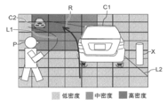
- FIG. 2 is an explanatory diagram of a calculation method by the first evaluation unit 25A for the evaluation value for each area on the captured image.
- the figure schematically shows an example of the latest image (currently captured image) taken while the vehicle is running by one of a plurality of cameras (for example, the left camera) included in the camera unit 10.
- This latest image shows the preceding vehicle C1 traveling along the road defined by the left and right lanes L1 and L2, in which the vehicle is gently curved.
- There is a pedestrian P near the left lane L1 and it is shown that the pedestrian P crosses the left lane L1 and enters the road, and moves in a direction crossing the road on which the own vehicle travels.
- an oncoming vehicle C2 approaching from a distance along the lanes L1 and L2 and a pole X installed on the right side of the road (right side of the lane L2) are installed.
- the expected course R of the own vehicle can be easily obtained from the camera parameters and the steering angle information.
- the lanes L1 and L2 can be identified from the image and obtained from the curvature thereof.
- the first evaluation unit 25A uses the score of the area on the start point side (lower side on the screen) of the predicted course R as the evaluation value of the parallax calculation density ( The numerical value) is relatively low, and the score of the area on the end point side (upper side on the screen) is relatively high.
- each region is scored based on the reference data (FIG. 3) so that the score increases from the start point to the end point along the expected course R.
- the reference data is preset and stored in a ROM or the like, and is read from the ROM into the first evaluation unit 25A (CPU). Thresholds S1 and S2 (S1 ⁇ S2) are set for this score.
- a region having a score of less than S1 is a low density region
- a region having a score of S1 or more and less than S2 is a medium density region
- a region having a score of S2 or more is a high density region. Evaluation values are classified. In the present embodiment, a case where the evaluation value of each region is set by dividing into three regions of "low density region", “medium density region", and "high density region” is illustrated, but the region may be divided into two. It may be divided into four or more areas.
- the second evaluation unit 25B creates the current estimated parallax image from the latest parallax image for a certain period of time read from the parallax image memory 27 and the vehicle speed information, and based on this estimated parallax image, the area is around.
- the evaluation value which is an index for determining the parallax calculation density, is determined.
- the region to which a high evaluation value is given by the second evaluation unit 25B is a region including an object that appears relatively small on the estimated parallax image.
- the second evaluation unit 25B evaluates and determines the distance (parallax) between the object captured in the latest image (object identified by shading) and the own vehicle in order to calculate the parallax from the latest image later by the parallax calculation unit 26. It will be one of the foundations. However, in order to calculate the parallax using the latest image, it is physically impossible to calculate the distance of the object reflected in the latest image in real time. Therefore, the second evaluation unit 25B reads a plurality of parallax images (most recent past parallax images) for the latest fixed period from the parallax image memory 27 via the past parallax image acquisition unit 24, and uses these plurality of parallax images.
- the estimated parallax image of the current time is calculated by adding the vehicle speed information. Then, the evaluation value of each region is calculated based on this estimated parallax image.
- the estimated parallax image is the current parallax image estimated and calculated from the past parallax image, and is estimated to have a correspondence relationship with the latest image.
- the past parallax image is an image calculated by the parallax calculation unit 26, and is calculated with a different calculation density for each region according to the evaluation of the region evaluation unit 25.
- the distances of various objects in addition to the information on the calculation density for each area, the distances of various objects (lanes, shoulders, preceding vehicles, oncoming vehicles, pedestrians, roadside trees, etc.) reflected in the images from the own vehicle, It contains information on the size of these objects on the image.
- the current estimated parallax image can be obtained from the parallax image for the most recent fixed period and the vehicle speed information.
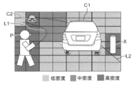
- FIG. 4 is a diagram schematically showing an example of an estimated parallax image calculated by the second evaluation unit 25B.
- the second evaluation unit 25B identifies the object to be parallax-calculated at high density from the estimated parallax image, and gives a relatively high score to the region including the object to be identified at high density.
- the object that is judged to have high-density parallax calculation is an object that appears small on the image. This is because, for such an object, the parallax cannot be calculated accurately even if the parallax is calculated at a low density using a low pixel image. For example, even if an object is not small in reality, it may appear only small in the image while it is far away.
- such an object may approach the own vehicle in a blink of an eye, but even such an object can be finely measured from a distance.
- the parallax can be calculated with sufficient accuracy even if the parallax is calculated with low density using a low pixel image, so it is necessary to calculate the parallax with high density using a high pixel image. Absent.
- the second evaluation unit 25B assigns a score to each area based on the reference data as shown in FIG.
- the reference data shown in the figure is created in advance and stored in a ROM or the like so that the closer the distance from the vehicle is, the higher the score is, while the smaller the size of the image is, the higher the score is.
- the horizontal axis represents the distance from the vehicle and the vertical axis represents the size on the image (first quadrant), which is divided by curves ⁇ 1 and ⁇ 2 representing the threshold value.
- the curves ⁇ 1 and ⁇ 2 can be, for example, inverse proportional curves.
- the score the closer the distance from the origin O is to the coordinates in FIG. 5, the higher the score.
- the region closer to the origin O than the curve ⁇ 1 is the high density region
- the region farther from the origin O than the curve ⁇ 2 is the low density region
- the region sandwiched between the curves ⁇ 1 and ⁇ 2 is the medium density region.
- the evaluation value of the area including this object differs depending on the size on the image. Even for an object with the same distance ⁇ , if the size on the image is large, it is determined to be a low density region because high-density parallax calculation is not required. On the contrary, if the size on the image is small, it is determined to be a high-density region because high-density parallax calculation is required.
- the evaluation value of the area including this object changes depending on the distance from the own vehicle. Even for an object having the same size ⁇ 1, if the distance from the vehicle is long, it is determined to be a low density region, and if it is close, it is determined to be a high density region.
- each region is set by dividing into three regions of “low density region”, “medium density region”, and “high density region” is illustrated, but the region may be divided into two regions. It may be divided into four or more areas.
- the evaluation value determination unit 25C determines the evaluation value for each region of the image based on the evaluation values of the first evaluation unit 25A and the second evaluation unit 25B. In particular, in the present embodiment, the evaluation value determination unit 25C determines the evaluation value for each area so that the total value of the calculated capacities of each area is within the set value.
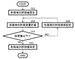
- FIG. 6 is a flowchart showing the procedure for determining the evaluation value for each region regarding the parallax calculation density in the evaluation value determination unit 25C.
- the evaluation value determination unit 25C uses each of the latest images to calculate the parallax.
- An evaluation value is set for the area (step S11).
- selection of the maximum value can be exemplified. This is a method of selecting the higher evaluation value for a region where the evaluation value on the latest image by the first evaluation unit 25A and the evaluation value on the estimated parallax image by the second evaluation unit 25B are different.
- the corresponding region on the latest image is set to the high-density region.
- the common evaluation value is selected for a region determined to be a low density region by both the first evaluation unit 25A and the second evaluation unit 25B.
- the evaluation value determination unit 25C calculates the calculation capacity of the parallax calculation based on the setting (step S12), and the calculated calculation capacity is equal to or less than the preset setting value. (Step S13). If the calculated capacity exceeds the setting, the evaluation value of each area is reset (step S14), and the procedure is returned to step S12.
- the method of setting the evaluation value for each area may be switched to the minimum value selection, or the evaluation may be divided by the average value of the scores for each area.
- step S14 If the determination is not satisfied again in step S13 through step S14, for example, in the region determined to be the medium density region or the high density region by the second evaluation unit 25B, in order from the region having the longest distance from the own vehicle, in step S14. It is conceivable to lower the evaluation value for each procedure. In order to reduce the number of repetitions of steps S12 to S14, the minimum value selection can be adopted for the processing of step S11.
- step S13 If it is determined in step S13 that the calculated capacity is equal to or less than the set capacity, the evaluation value determining unit 25C determines the evaluation value of each area with the setting at that time (step S15), and outputs the evaluation value to the parallax calculation unit 26 together with the memory such as RAM. Then, the flowchart of FIG. 6 is terminated.
- the area evaluation unit 25 sequentially changes the calculation density of the parallax calculation in each area on the captured image according to the situation.
- the parallax calculation unit 26 calculates the parallax with high pixels for a region where the evaluation value determined by the region evaluation unit 25 is relatively high for a plurality of latest images simultaneously captured by the plurality of cameras, and the region evaluation unit 25 calculates the parallax. Parallax is calculated with low pixels in a region where the determined evaluation value is relatively low.
- the calculated disparity image is stored in the disparity image memory 27, and the own vehicle is used as basic information for vehicle control such as warning operation (warning sound by buzzer, warning display by monitor, etc.) for the driver and automatic braking. It is output to the in-vehicle computer (not shown).
- the parallax calculation unit 26 sets a region of a predetermined size (for example, 8 ⁇ 8 pixels) including the points of interest at arbitrary coordinates (a, b) in the image captured by the camera on the left side, for example.
- a predetermined size for example, 8 ⁇ 8 pixels
- this area of a predetermined size is referred to as a "window”.
- a window having the same position and size on the photographed image as the window set in the image captured on the left is set.
- the parallax calculation unit 26 calculates the SAD (Sum of Absolute DIfference) of each window for the left and right captured images. SAD is given by the following formula.
- IL (x, y) is the pixel shading value of the coordinates (a + i, b + j) in the window of the image taken by the left camera
- IR (x, y) is the coordinates in the window of the image taken by the right camera (x, y). It is a shading value at a + i + c, b + j).
- c is the amount of lateral displacement of the position of the window on the image captured by the right camera with respect to the window on the image captured by the left camera (in the present embodiment, the amount of displacement in the vertical direction is 0). Left and right cameras are installed).
- Wx and Wy are the width (horizontal size) and height (vertical size) of the window.
- the amount of misalignment c that minimizes the SAD value is the parallax of the points of interest (a, b).
- parallax information can be obtained by executing such parallax for all pixels of the captured image, but the parallax calculation unit 26 differs in the parallax calculation density for each region in the captured image according to the evaluation of the region evaluation unit 25. Attach.
- the block size is a setting and can be changed. However, it is premised that the block in the low pixel area is larger than the block in the medium pixel area.
- the high pixel region does not necessarily have to be configured to calculate parallax for all pixels, and the parallax calculation density is higher (the block size is smaller) than in other regions, and the desired calculation density can be secured. Just do it.
- the evaluation value for each area on the captured image is determined based on the vehicle information of the own vehicle. Unlike the case of area analysis using a low-pixel image with thinned pixels as in rough analysis, it is possible to accurately calculate the distance to the own vehicle with high resolution depending on the situation even for an object that appears small on the image.
- highly reliable parallax information can be calculated by improving the validity of region selection.
- the current estimated parallax image is created from the latest parallax image for a certain period and vehicle speed information, and a high evaluation value is given to the area including an object that appears relatively small on the estimated parallax image.
- the evaluation value for each region is comprehensively determined from the evaluation value based on the expected course by the first evaluation unit 25A and the evaluation value based on the size on the image by the second evaluation unit 25B. ..
- the evaluation value is finally determined by combining both evaluations for each region (or for the entire captured image as a whole). ) A more reasonable evaluation value can be obtained. As a result, highly reliable parallax information can be calculated.
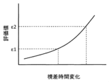
- FIG. 7 is a schematic diagram of another example of the reference data used in the second evaluation unit.
- the second evaluation unit 25B the time change of the parallax for a certain period is relative. A high evaluation value may be given to a large area.
- either one of the evaluation methods from the two viewpoints of the size of the object on the image and the time change of the parallax may be adopted, or both may be adopted.
- reference data is stored in a ROM or the like so that the score increases as the time change of parallax increases. Then, in the second evaluation unit 25B, the score is calculated for each region (or object) based on the time change of the parallax for each region (or object) obtained from the latest plurality of parallax images and the read reference data. .. Thresholds ⁇ 1 and ⁇ 2 ( ⁇ 1 ⁇ 2) are set for this score.
- a region with a score of less than ⁇ 1 is a low density region
- a region with a score of ⁇ 1 or more and less than ⁇ 2 is a medium density region
- a region with a score of ⁇ 2 or more is a high density region.
- the evaluation value of the object itself may be calculated by using the object (such as the preceding vehicle C1 in FIG. 2) itself reflected in the captured image as the evaluation area.
- the evaluation value data of each region of the simulated image assuming a horizontal area without obstacles is stored in the memory as an initial value, and the evaluation value determination unit 25C reads this data and the parallax calculation unit 26. To output to.
- Vehicle speed information and steering angle information are exemplified as vehicle information acquired by the vehicle information acquisition unit 23 and input to the area evaluation unit 25, but other vehicle information can also be appropriately used for evaluation calculation.
- the inclination information of whether the own vehicle is tilted forward or backward can be used for processing such as offsetting the expected course or the like in the vertical direction on the image according to the inclination angle.
- the information on turning on and off the headlights can be used to distinguish between the illuminated area and the unlit area on the captured image and adjust the brightness difference of the captured image.
- the operation information of the wiper can be used to prevent this.
- information from a positioning device for example, GPS mounted on the vehicle is input, and the current value and its surrounding data are collated with the captured image and used to calculate the curvature of the road and the expected course, or the surrounding buildings. It can also be used to match objects.
- a positioning device for example, GPS
- the configuration in which the area evaluation unit 25 includes two evaluation units of the first evaluation unit 25A and the second evaluation unit 25B has been described as an example, but only one of them has been described.
- the configuration may be omitted.
- the evaluation value determination unit 25C is inevitably unnecessary.
- the evaluation value determination unit 25C determines the evaluation value for each area so that the total value of the calculated capacities of each area is within the set value or less is described as an example, this function can be omitted. ..
- the evaluation value data set in step S11 of FIG. 6 can be output to the parallax calculation unit 26 as it is.
Landscapes
- Engineering & Computer Science (AREA)
- Multimedia (AREA)
- Signal Processing (AREA)
- Physics & Mathematics (AREA)
- General Physics & Mathematics (AREA)
- Library & Information Science (AREA)
- Computer Vision & Pattern Recognition (AREA)
- Theoretical Computer Science (AREA)
- Image Analysis (AREA)
- Traffic Control Systems (AREA)
- Image Processing (AREA)
Abstract
高解像度の撮影画像の一部について他の部分に比べて高解像度で視差情報を計算するに当たって領域の選択の妥当性の向上により高信頼性の視差情報を計算する。自動車と前記自動車の外界の障害物との距離を計算するステレオ画像処理装置において、前記自動車の外界について複数のカメラで連続的に撮影される撮影画像を保存する撮影画像メモリと、前記自動車の操舵角情報及び車速情報の少なくとも一方を基に前記撮影画像上の領域毎の評価値を決定する領域評価部と、前記複数のカメラでそれぞれ撮影された複数の最新画像について、前記領域評価部で決定された評価値が相対的に高い領域について高画素で視差計算し、前記領域評価部で決定された評価値が相対的に低い領域について低画素で視差計算する視差計算部とを備える。
Description
本発明は、複数のカメラの撮影画像から視差を計算するステレオ画像処理装置及びステレオ画像処理方法に関する。
近年、予防安全技術の発展と自動車の自動運転の需要の高まりにより車外の状況を高精度に識別する技術が強く求められている。ステレオカメラは、撮影画像から得られる物体の形状や濃淡、視差情報から得られる物体の自動車からの距離等、豊富な情報が得られる点で特に需要が高い。このステレオカメラの用途拡大と自動運転への応用のためには、これまでよりも解像度の高いカメラを使用する必要がある。しかし、ステレオカメラは視差を計算するために必要な演算コストが非常に高く、単に高解像度のカメラを用いても従来の画像処理をそのまま適用したのではAEB等の制御で要求される時間内で演算が完遂できない。そのため高解像度な視差計算が必要な領域を撮影画像から抽出し、領域を絞って高解像度な視差計算を実行する必要がある。これに関し、特許文献1には、まず複数の低解像度画像を用いて計算した視差から必要な領域を抽出し、次に複数の高解像度画像を用いて必要な領域について正確な視差を計算することが記載されている。
しかし、低解像度画像を用いて領域を抽出する方法では、領域の抽出段階における視差計算の解像度が低いことから、真に高解像度な視差計算が必要な領域が抽出できているのか信頼性の面で課題が存在する。低画素画像では小さく映る物体は正確に距離を計算できない。
本発明の目的は、高解像度の撮影画像の一部について他の部分に比べて高解像度で視差情報を計算するに当たって領域の選択の妥当性の向上により高信頼性の視差情報を計算できるステレオ画像処理装置及びステレオ画像処理方法を提供することにある。
上記目的を達成するために、本発明は、自動車と前記自動車の外界の障害物との距離を計算するステレオ画像処理装置であって、前記自動車の外界について複数のカメラで連続的に撮影される撮影画像を保存する撮影画像メモリと、前記自動車の操舵角情報及び車速情報の少なくとも一方を基に前記撮影画像上の領域毎の評価値を決定する領域評価部と、前記複数のカメラでそれぞれ撮影された複数の最新画像について、前記領域評価部で決定された評価値が相対的に高い領域について高画素で視差計算し、前記領域評価部で決定された評価値が相対的に低い領域について低画素で視差計算する視差計算部とを備える。
本発明によれば、高解像度の撮影画像の一部について他の部分に比べて高解像度で視差情報を計算するに当たって領域の選択の妥当性の向上により高信頼性の視差情報を計算することができる。
以下に図面を用いて本発明の実施の形態を説明する。
-ステレオ画像処理装置-
図1は本発明の一実施形態に係るステレオ画像処理装置のブロック図である。同図に示したステレオ画像処理装置は、カメラユニット10と画像処理ユニット20とを組み合わせたユニットであり、例えば自動車の運転室内においてルームミラーの裏側(前方を向いた面)に取り付けられてる。このステレオ画像処理装は、自車と外界(例えば自車の前方)の障害物との距離を計算し出力する。「自車」とは以下に説明するステレオ画像処理装置を搭載した自動車のことである。
図1は本発明の一実施形態に係るステレオ画像処理装置のブロック図である。同図に示したステレオ画像処理装置は、カメラユニット10と画像処理ユニット20とを組み合わせたユニットであり、例えば自動車の運転室内においてルームミラーの裏側(前方を向いた面)に取り付けられてる。このステレオ画像処理装は、自車と外界(例えば自車の前方)の障害物との距離を計算し出力する。「自車」とは以下に説明するステレオ画像処理装置を搭載した自動車のことである。
-カメラユニット-
カメラユニット10は複数のカメラを含んで構成されている。本実施形態では、左右に並べてステレオ画像処理装置に取り付けられた2つのカメラでカメラユニット10が構成されているとする。2つのカメラの撮影画像では、自車から近距離にある物体ほど撮影画像上の位置が左右方向にずれる。このずれ量が視差であり、この視差を計算することで2つのカメラの位置関係が既知であることから自車から対象物体までの距離を計測することができる。
カメラユニット10は複数のカメラを含んで構成されている。本実施形態では、左右に並べてステレオ画像処理装置に取り付けられた2つのカメラでカメラユニット10が構成されているとする。2つのカメラの撮影画像では、自車から近距離にある物体ほど撮影画像上の位置が左右方向にずれる。このずれ量が視差であり、この視差を計算することで2つのカメラの位置関係が既知であることから自車から対象物体までの距離を計測することができる。
なお、本実施形態では2つのカメラでカメラユニット10を構成した場合を例示したが、カメラユニット10に3つ以上のカメラが含まれる構成としても良い。また、カメラユニット10が自車の前方領域を撮影する構成を例示挙げて説明するが、左方領域、右方領域、或いは後方領域を撮影する構成であっても良い。本実施形態における2つのカメラの撮影画像の視差は左右方向にのみ発生し、上下方向には視差が発生しないようにしてある。
-画像処理ユニット-
画像処理ユニット20は、インターフェースやCPU、RAM、ROM、メモリ、タイマーを含んで構成されたコンピュータである。この画像処理ユニット20は、画像取得部21、撮影画像メモリ22、車両情報取得部23、過去視差画像取得部24、領域評価部25、視差計算部26、視差画像メモリ27等の要素を含んで構成されている。画像取得部21、撮影画像メモリ22、車両情報取得部23、過去視差画像取得部24、領域評価部25、視差計算部26、視差画像メモリ27は、機能を構成要素として模式的に表したものであり、インターフェースやCPU、メモリ等でそれぞれ適宜構成される。
画像処理ユニット20は、インターフェースやCPU、RAM、ROM、メモリ、タイマーを含んで構成されたコンピュータである。この画像処理ユニット20は、画像取得部21、撮影画像メモリ22、車両情報取得部23、過去視差画像取得部24、領域評価部25、視差計算部26、視差画像メモリ27等の要素を含んで構成されている。画像取得部21、撮影画像メモリ22、車両情報取得部23、過去視差画像取得部24、領域評価部25、視差計算部26、視差画像メモリ27は、機能を構成要素として模式的に表したものであり、インターフェースやCPU、メモリ等でそれぞれ適宜構成される。
-画像取得部-
画像取得部21は、例えばカメラユニット10の2台のカメラの撮像画像を入力するインターフェースである。各カメラが有線又は無線で画像取得部21に接続されており、この画像取得部21を介してカメラユニット10で撮影された撮影画像が随時画像処理ユニット20に入力される。
画像取得部21は、例えばカメラユニット10の2台のカメラの撮像画像を入力するインターフェースである。各カメラが有線又は無線で画像取得部21に接続されており、この画像取得部21を介してカメラユニット10で撮影された撮影画像が随時画像処理ユニット20に入力される。
-撮影画像メモリ-
撮影画像メモリ22は、HDDやRAM等のメモリで構成され、自車の外界(前方領域)についてカメラユニット10の複数のカメラで連続的に撮影されて画像取得部21に入力される撮影画像を保存する。撮影画像メモリ22には、2つのカメラで同時撮影された一対の撮影画像が、これらカメラのフレームレートで逐次保存される。所定の記憶領域が一杯になったら、例えば古い撮影画像から順に新しい撮影画像に上書きされていく。
撮影画像メモリ22は、HDDやRAM等のメモリで構成され、自車の外界(前方領域)についてカメラユニット10の複数のカメラで連続的に撮影されて画像取得部21に入力される撮影画像を保存する。撮影画像メモリ22には、2つのカメラで同時撮影された一対の撮影画像が、これらカメラのフレームレートで逐次保存される。所定の記憶領域が一杯になったら、例えば古い撮影画像から順に新しい撮影画像に上書きされていく。
-視差画像メモリ-
視差画像メモリ27は、過去に視差計算部26で計算された複数の視差画像を保存する(視差計算部26で計算された視差画像が逐次保存されていく)。視差画像メモリ27は撮影画像メモリ22と同様にHDDやRAM等のメモリで構成され、撮影画像メモリ22と同一のメモリで兼ねても良いし、異なるメモリに分けても良い。所定の記憶領域が一杯になったら、例えば古い視差画像から順に新しい視差画像に上書きされていく。
視差画像メモリ27は、過去に視差計算部26で計算された複数の視差画像を保存する(視差計算部26で計算された視差画像が逐次保存されていく)。視差画像メモリ27は撮影画像メモリ22と同様にHDDやRAM等のメモリで構成され、撮影画像メモリ22と同一のメモリで兼ねても良いし、異なるメモリに分けても良い。所定の記憶領域が一杯になったら、例えば古い視差画像から順に新しい視差画像に上書きされていく。
-車両情報取得部-
車両情報取得部23は、例えば自車に搭載されたCAN(Controller Area Network)から自車の車両情報を入力するインターフェースである。「車両情報」とは、車速や操舵角、水平に対する自車の傾斜角等、自車に搭載された各種センサで随時検出される操作情報や姿勢情報等のことである。CANが有線又は無線で画像取得部21に接続されており、本実施形態では、車両情報取得部23を介してCANから画像処理ユニット20に少なくとも車速情報と操舵角情報が車両情報として入力される。車両情報取得部23は、入力された車両情報をRAM等のメモリに逐次記録すると共に、所定のタイミングで領域評価部25の第1評価部25A(後述)及び第2評価部25B(後述)に出力する。
車両情報取得部23は、例えば自車に搭載されたCAN(Controller Area Network)から自車の車両情報を入力するインターフェースである。「車両情報」とは、車速や操舵角、水平に対する自車の傾斜角等、自車に搭載された各種センサで随時検出される操作情報や姿勢情報等のことである。CANが有線又は無線で画像取得部21に接続されており、本実施形態では、車両情報取得部23を介してCANから画像処理ユニット20に少なくとも車速情報と操舵角情報が車両情報として入力される。車両情報取得部23は、入力された車両情報をRAM等のメモリに逐次記録すると共に、所定のタイミングで領域評価部25の第1評価部25A(後述)及び第2評価部25B(後述)に出力する。
-過去視差画像取得部-
過去視差画像取得部24は、視差計算部26で過去に計算された視差画像を視差画像メモリ27から入力するインターフェースである。この過去視差画像取得部24は、最新の一定期間分の視差画像を視差画像メモリ27から読み込んで領域評価部25の第2評価部25B(後述)に出力する。「最新の一定期間」とは、現在時刻から所定時間だけ遡った指定時刻を始期、現在時刻を終期とする期間であり、所定時間は設定値である。
過去視差画像取得部24は、視差計算部26で過去に計算された視差画像を視差画像メモリ27から入力するインターフェースである。この過去視差画像取得部24は、最新の一定期間分の視差画像を視差画像メモリ27から読み込んで領域評価部25の第2評価部25B(後述)に出力する。「最新の一定期間」とは、現在時刻から所定時間だけ遡った指定時刻を始期、現在時刻を終期とする期間であり、所定時間は設定値である。
-領域評価部-
領域評価部25は、自車の操舵角情報及び車速情報の少なくとも一方(本実施形態では双方)を基に撮影画像上の領域毎の評価値を決定する処理を構成要素として模式的に表したものであり、例えばCPUにより実行される。本実施形態では、撮影画像上の領域を升目状に区分した場合を例に挙げて説明する(図2)。領域評価部25は、第1評価部25A、第2評価部25B、評価値決定部25Cを含んで構成されている。第1評価部25A、第2評価部25B、評価値決定部25Cは機能を構成要素として模式的に表したものであり、それぞれ例えばCPUにより実行される。
領域評価部25は、自車の操舵角情報及び車速情報の少なくとも一方(本実施形態では双方)を基に撮影画像上の領域毎の評価値を決定する処理を構成要素として模式的に表したものであり、例えばCPUにより実行される。本実施形態では、撮影画像上の領域を升目状に区分した場合を例に挙げて説明する(図2)。領域評価部25は、第1評価部25A、第2評価部25B、評価値決定部25Cを含んで構成されている。第1評価部25A、第2評価部25B、評価値決定部25Cは機能を構成要素として模式的に表したものであり、それぞれ例えばCPUにより実行される。
・第1評価部
第1評価部25Aは、2つのカメラのうちの1つ(例えば左のカメラ)で撮影された最新画像を撮影画像メモリ22から読み込み、車両情報取得部23から入力された現在の操舵角情報を基に最新画像上で自車の予想進路を演算する。加えて、この第1評価部25Aは、最新画像上の予想進路上で自車から相対的に遠距離にある最新画像上の領域に高い評価値を付ける。「最新画像」とは、撮影時刻が最も新しい撮影画像であり、実質的には現在時刻の撮影画像を意図している。第1評価部25Aについて以下に詳しく説明する。
第1評価部25Aは、2つのカメラのうちの1つ(例えば左のカメラ)で撮影された最新画像を撮影画像メモリ22から読み込み、車両情報取得部23から入力された現在の操舵角情報を基に最新画像上で自車の予想進路を演算する。加えて、この第1評価部25Aは、最新画像上の予想進路上で自車から相対的に遠距離にある最新画像上の領域に高い評価値を付ける。「最新画像」とは、撮影時刻が最も新しい撮影画像であり、実質的には現在時刻の撮影画像を意図している。第1評価部25Aについて以下に詳しく説明する。
図2は撮影画像上の領域毎の評価値についての第1評価部25Aによる計算方法の説明図である。同図は、カメラユニット10に含まれる複数のカメラのうちの1つ(例えば左のカメラ)により自車の走行中に撮影された最新画像(現在の撮影画像)の例を模式的に表している。この最新画像には、自車は緩やかにカーブした左右の車線L1,L2で画定された道路に沿って走行する先行車C1が映っている。左側の車線L1の付近には歩行者Pが居り、この歩行者Pが左側の車線L1を超えて道路に進入し、自車の走行する道路を横切る方向に移動する様子が映っている。また、車線L1,L2に沿って遠方から接近してくる対向車C2や道路の右側(車線L2の右側)に設置されたポールXが設置されている。
カメラユニット10は自車に対して姿勢が固定されているので、カメラパラメータと操舵角情報から簡易的に自車の予想進路Rを求めることができる。正確に自車の予想進路Rを求める場合、車線L1,L2を画像から識別しその曲率から求めることもできる。
例えば図2において矢印で示したように予想進路Rが設定されたら、第1評価部25Aは視差計算密度の評価値として、予想進路Rの始点側(画面上の下側)の領域のスコア(数値)を相対的に低くし、終点側(画面上の上側)の領域のスコアを相対的に高く付ける。一例としては、予想進路Rに沿って始点から終点に向かうに連れてスコアが高くなるようにリファレンスデータ(図3)を基に各領域にスコアを付ける。リファレンスデータは予め設定されてROM等に保存されており、ROMから第1評価部25A(CPU)に読み込まれる。このスコアについて閾値S1,S2(S1<S2)を設定しておき、例えばスコアがS1未満の領域は低密度領域、S1以上S2未満の領域は中密度領域、S2以上の領域は高密度領域として評価値が区分される。本実施形態では「低密度領域」「中密度領域」「高密度領域」の3つに分けて各領域の評価値を設定する場合を例示しているが、領域の区分は2つでも良いし4つ以上の領域に分けるようにしても良い。
・第2評価部
第2評価部25Bは、視差画像メモリ27から読み込んだ最新の一定期間分の視差画像と車速情報とから現在の推定視差画像を作成し、この推定視差画像を基に領域頃に視差計算密度決定の指標となる評価値を判定する。この第2評価部25Bによって高い評価値が付けられる領域は、推定視差画像上で相対的に小さく映った物体を含む領域である。第2評価部25Bは、後に視差計算部26で最新画像から視差計算するために、最新画像で捉えられた物体(濃淡で識別される物体)と自車との距離(視差)を評価判定の基礎の1つとする。但し、最新画像を用いて視差計算するために、その最新画像に映った物体の距離をリアルタイムで計算することは物理的に不可能である。そこで、第2評価部25Bでは、過去視差画像取得部24を介して視差画像メモリ27から最新の一定期間分の複数の視差画像(直近の過去視差画像)を読み込み、これら複数の視差画像を用いて車速情報を加味して現在時刻の推定視差画像を計算する。そして、この推定視差画像に基づいて各領域の評価値を計算する。なお、推定視差画像は過去の視差画像から推定演算した現在の視差画像であり、最新画像と対応関係にあることが推定される。
第2評価部25Bは、視差画像メモリ27から読み込んだ最新の一定期間分の視差画像と車速情報とから現在の推定視差画像を作成し、この推定視差画像を基に領域頃に視差計算密度決定の指標となる評価値を判定する。この第2評価部25Bによって高い評価値が付けられる領域は、推定視差画像上で相対的に小さく映った物体を含む領域である。第2評価部25Bは、後に視差計算部26で最新画像から視差計算するために、最新画像で捉えられた物体(濃淡で識別される物体)と自車との距離(視差)を評価判定の基礎の1つとする。但し、最新画像を用いて視差計算するために、その最新画像に映った物体の距離をリアルタイムで計算することは物理的に不可能である。そこで、第2評価部25Bでは、過去視差画像取得部24を介して視差画像メモリ27から最新の一定期間分の複数の視差画像(直近の過去視差画像)を読み込み、これら複数の視差画像を用いて車速情報を加味して現在時刻の推定視差画像を計算する。そして、この推定視差画像に基づいて各領域の評価値を計算する。なお、推定視差画像は過去の視差画像から推定演算した現在の視差画像であり、最新画像と対応関係にあることが推定される。
過去の視差画像は視差計算部26で計算された画像であり、領域評価部25の評価に従って領域毎に異なる計算密度で計算されている。過去の視差画像には、こうした領域毎の計算密度の情報の他、画像に映った種々の物体(車線、路肩、先行車、対向車、歩行者、街路樹等)の自車からの距離、これら物体の画像上の大きさの情報が含まれている。これらの直近の一定期間分の視差画像と車速情報とから現在の推定視差画像が得られる。
図4は第2評価部25Bで計算した推定視差画像の一例を模式的に表した図である。第2評価部25Bは、推定視差画像から高密度に視差計算すべき物体を識別し、高密度に識別すべき物体を含む領域に相対的に高いスコアを付ける。ここで高密度に視差計算すべきと判断される物体は、画像上に小さく映った物体である。このような物体については、低画素画像を用いて低密度で視差計算しても精度良く視差を計算することができないためである。例えば現実には決して小さくない物体であっても、遠方にあるうちは画像には小さくしか映らないものがある。自車との相対速度によってはこのようなものが瞬く間に自車に接近することもあり得るが、このような物体についても遠方にあるうちから子細に測距することができる。反対に大きく映った物体であれば低画素画像を用いて低密度で視差計算しても十分な精度で視差を計算することができるため、高画素画像を用いて高密度で視差計算する必要がない。
一例として、第2評価部25Bは、図5に示したようなリファレンスデータを基に各領域にスコアを付ける。同図に示したリファレンスデータは、自車からの距離が近いほどスコアが高くなる一方で、画像上の大きさが小さい物体ほどスコアが高くなるように予め作成されてROM等に保存されており、ROMから第2評価部25B(CPU)に読み込まれる。同図のリファレンスデータでは、横軸が自車からの距離、縦軸が画像上の大きさを表す座標系(第1象限)が、閾値を表す曲線γ1,γ2で区分されている。曲線γ1,γ2は、例えば反比例曲線とすることができる。スコアについては、図5中で原点Oからの距離が近い座標ほど高い。曲線γ1よりも原点Oに近い領域が高密度領域、曲線γ2よりも原点Oから遠い領域が低密度領域、曲線γ1,γ2で挟まれた領域が中密度領域である。例えば自車からの距離が同値(=α)の物体であっても、この物体を含む領域の評価値は画像上の大きさで異なってくる。同じ距離αの物体でも、画像上の大きさが大きければ、高密度な視差計算を要しないため低密度領域と判定される。反対に、画像上の大きさが小さければ、高密度な視差計算を要するため高密度領域と判定される。
見方を変えれば、画像上の大きさが同じ(=β1)物体であっても、この物体を含む領域の評価値は自車からの距離で変化する。同じ大きさβ1の物体でも、自車からの距離が遠ければ低密度領域と判定され、近ければ高密度領域と判定される。
いずれにしても、推定視差画像上の大きさが小さい物体ほど高密度な視差計算が必要であると判定され、例えば画像上の大きさが一定値(=β2)よりも小さい物体に関しては、自車からの距離に関係なく無条件に高密度領域に区分される。
図5においても、「低密度領域」「中密度領域」「高密度領域」の3つに分けて各領域の評価値を設定する場合を例示しているが、領域の区分は2つでも良いし4つ以上の領域に分けるようにしても良い。
・評価値決定部
評価値決定部25Cは、第1評価部25Aと第2評価部25Bの評価値を基に画像の領域毎の評価値を決定する。特に本実施形態において、評価値決定部25Cは、各領域の計算容量の合計値が設定値以下に収まるように領域毎の評価値を決定する。
評価値決定部25Cは、第1評価部25Aと第2評価部25Bの評価値を基に画像の領域毎の評価値を決定する。特に本実施形態において、評価値決定部25Cは、各領域の計算容量の合計値が設定値以下に収まるように領域毎の評価値を決定する。
図6は評価値決定部25Cにおける視差計算密度に関する領域毎の評価値の決定手順を表すフローチャートである。第1評価部25A及び第2評価部25Bで評価値が計算されたら、同図に示したように、評価値決定部25Cは、最新画像を用いて視差計算をするに当たり、最新画像上の各領域について評価値を設定する(ステップS11)。評価値の設定方法は、例えば最大値選択が例示できる。第1評価部25Aによる最新画像上の評価値と第2評価部25Bによる推定視差画像上の評価値とが異なる領域について高い方の評価値を選択する方法である。例えば第1評価部25Aで高密度領域、第2評価部25Bで中密度領域と判定されている領域については、最新画像上の対応領域を高密度領域に設定する。第1評価部25Aと第2評価部25Bの評価値が等しい領域については、その共通の評価値を選択する。例えば第1評価部25Aと第2評価部25Bの双方で低密度領域と判定されている領域については、最新画像上の対応領域を低密度領域に設定する。
最新画像上の各領域の評価値を設定したら、評価値決定部25Cは、設定に基づいた視差計算の計算容量を計算し(ステップS12)、計算した計算容量が予め設定した設定値以下であるかを判定する(ステップS13)。仮に計算容量が設定を超えている場合、各領域の評価値を再設定し(ステップS14)、ステップS12に手順を戻す。ステップS14の手順では、例えば領域毎の評価値の設定方法を最小値選択に切り換えたり、領域毎のスコアの平均値で評価を区分したりすることが例示できる。ステップS14を経てステップS13で再び判定が満たされなければ、例えば第2評価部25Bにおいて中密度領域又は高密度領域と判定された領域について、自車からの距離が遠い領域から順に、ステップS14の手順の度に評価値を下げていくことが考えられる。ステップS12-S14の繰り返し数を抑える上では、ステップS11の処理に最小値選択を採用することもできる。
ステップS13で計算容量が設定容量以下であると判定したら、評価値決定部25Cはその時点の設定で各領域の評価値を決定し(ステップS15)、RAM等のメモリと共に視差計算部26に出力して図6のフローチャートを終了する。
以上のように、領域評価部25により撮影画像上の各領域における視差計算の計算密度が状況に応じて逐次変更される。
-視差計算部-
視差計算部26は、複数のカメラでそれぞれ同時撮影された複数の最新画像について、領域評価部25で決定された評価値が相対的に高い領域について高画素で視差計算し、領域評価部25で決定された評価値が相対的に低い領域について低画素で視差計算する。計算した視差画像は、視差画像メモリ27に保存されると共に、運転者に対する警告動作(ブザーによる警告音、モニタによる警告表示等)や自動ブレーキ等の車両制御の基礎情報としてCANを介して自車の車載コンピュータ(不図示)に出力される。
視差計算部26は、複数のカメラでそれぞれ同時撮影された複数の最新画像について、領域評価部25で決定された評価値が相対的に高い領域について高画素で視差計算し、領域評価部25で決定された評価値が相対的に低い領域について低画素で視差計算する。計算した視差画像は、視差画像メモリ27に保存されると共に、運転者に対する警告動作(ブザーによる警告音、モニタによる警告表示等)や自動ブレーキ等の車両制御の基礎情報としてCANを介して自車の車載コンピュータ(不図示)に出力される。
視差計算部26においては、視差を計算するに当たり、例えば左側のカメラによる撮影画像において任意の座標(a,b)の注目点を含む所定サイズ(例えば8×8画素)の領域を設定する。以降、この所定サイズの領域を「窓」と呼ぶ。同時に、右側のカメラによる撮影画像においても、左の撮影画像内に設定した窓と撮影画像上の位置及びサイズが等しい窓を設定する。視差計算部26は、左右の撮影画像について各窓のSAD(Sum of Absolute DIfference)を計算する。SADは以下の式で与えられる。

但し、IL(x,y)は左側のカメラによる撮影画像の窓内の座標(a+i,b+j)の画素の濃淡値、IR(x,y)は右側のカメラによる撮影画像の窓内の座標(a+i+c,b+j)での濃淡値である。cは左側のカメラによる撮影画像上の窓に対する右側のカメラによる撮影画像上の窓の位置の左右方向の位置ずれ量である(本実施形態では、上下方向の位置ずれ量は0となるように左右のカメラが設置されているとする)。Wx,Wyは窓の幅(左右方向のサイズ)と高さ(上下方向のサイズ)である。
上の式から、左右のカメラによる撮影画像上の窓内の対応画素の濃淡値の差(絶対値)の合計(=SAD)が算出される。視差計算部26は0から設定値(=探索数cmax)の範囲でcの値を順次変えて(つまり右側のカメラによる撮影画像上の窓を順次ずらして)SADの計算を繰り返し、SAD値が最小となるずれ量cを探索する。SAD値が最小となる位置ずれ量cが注目点(a,b)の視差である。
このような視差を撮影画像の全画素について実行することで子細な視差情報が得られるが、視差計算部26では、領域評価部25の評価に従って撮影画像内の領域毎に視差の計算密度に差を付ける。本実施形態では、領域評価部25において低密度領域と判定した領域については、例えば4×4(=16)画素のブロックで領域を区画し、各ブロックから抽出した1画素(例えば各ブロックの左上の画素)についてのみ上記の視差計算を実行する。中密度領域と判定した領域については、例えば2×2(=4)画素のブロックで領域を区画し、各ブロックから抽出した1画素(例えば各ブロックの左上の画素)についてのみ視差計算を実行する。高密度領域と判定した領域については、全画素について視差計算を実行する(言い換えれば、ブロックのサイズが1×1=1画素)。この場合、高密度領域に対して、中密度領域の計算密度は1/4であり、低密度領域の計算密度は1/16である。
なお、ブロックのサイズは設定であって変更可能である。但し、低画素領域のブロックが中画素領域のブロックより大きいことが前提である。また、高画素領域は必ずしも全画素について視差計算をする構成とする必要はなく、他の領域に比べて視差の計算密度が高く(ブロックのサイズが小さく)、所望の計算密度が確保できていれば良い。
-効果-
(1)本実施形態においては、自車の車両情報を基に撮影画像上の領域毎の評価値を決定する。粗分析ように画素を間引いた低画素画像で領域分析する場合と異なり、画像上に小さく映った物体についても状況に応じて高解像度で正確に自車との距離を計算することができる。高解像度の撮影画像の一部について他の部分に比べて高解像度で視差情報を計算するに当たって領域の選択の妥当性の向上により高信頼性の視差情報を計算できる。然るべき物体を選択的に高密度で視差計算し、必要性の低い物体については視差計算の密度を下げることで画像全体についての計算容量を抑えることができ、応答性が向上する。
(1)本実施形態においては、自車の車両情報を基に撮影画像上の領域毎の評価値を決定する。粗分析ように画素を間引いた低画素画像で領域分析する場合と異なり、画像上に小さく映った物体についても状況に応じて高解像度で正確に自車との距離を計算することができる。高解像度の撮影画像の一部について他の部分に比べて高解像度で視差情報を計算するに当たって領域の選択の妥当性の向上により高信頼性の視差情報を計算できる。然るべき物体を選択的に高密度で視差計算し、必要性の低い物体については視差計算の密度を下げることで画像全体についての計算容量を抑えることができ、応答性が向上する。
(2)自車の進路上或いは進路付近に存在する障害物については視差情報の精度が要求される。しかし、遠方の障害物については現実の大きさによっては画像に小さくしか映らない場合がある。そこで、本実施形態では、撮影画像の領域毎の評価値を計算するに当たり、操舵角情報を基に1枚の最新画像上で自車の予想進路を演算し、予想進路上で自車から相対的に遠距離にある領域に高い評価値を付ける。これにより進路上又は進路付近の物体について正確に視差を計算することができ、高信頼性の視差情報を計算することができる。
(3)また、最新の一定期間分の視差画像と車速情報とから現在の推定視差画像を作成し、推定視差画像上で相対的に小さく映った物体を含む領域に高い評価値を付ける。このように直近の視差画像と車速情報から視差情報を含んだ現在の視差画像を推定計算することで、画像に映った各物体について自車からの距離を知ることができる。自車から近距離にある物体について視差の計算密度を高く設定できることは勿論、画像上に小さく映った物体については自車からの距離が遠くても高い計算密度の視差情報が得られ、高信頼性の視差情報を計算することができる。
(4)特に本実施形態では第1評価部25Aによる予想進路に基づく評価値、及び第2評価部25Bにより画像上の大きさに基づく評価値から、領域毎の評価値を総合的に決定する。この場合、いずれか一方の評価方法では真に妥当な評価がされない状況であっても、双方の評価を総合して評価値を最終決定することで各領域について(又は撮影画像全体について全体的に)より妥当な評価値を得ることができる。ひいては高信頼性の視差情報を計算することができる。
(5)また、各領域の計算容量の合計値が設定値以下に収まるように領域毎の評価値を決定することで全体的な計算負荷を安定的に抑え、応答性良く高信頼性の視差情報を計算することができる。
-変形例-
図7は第2評価部で用いるリファレンスデータの他の例の模式図である。上記実施形態では、推定視差画像を用いて画像上における物体の大きさに注目して評価値を計算する例を説明したが、例えば第2評価部25Bで一定期間分の視差の時間変化が相対的に大きい領域に高い評価値が付けられるようにしても良い。第2評価部25Bにおいては、画像上の物体の大きさ、視差の時間変化の2つの観点の評価方法のうちいずれか一方を採用する構成としても良いし、双方を採用する構成としても良い。
図7は第2評価部で用いるリファレンスデータの他の例の模式図である。上記実施形態では、推定視差画像を用いて画像上における物体の大きさに注目して評価値を計算する例を説明したが、例えば第2評価部25Bで一定期間分の視差の時間変化が相対的に大きい領域に高い評価値が付けられるようにしても良い。第2評価部25Bにおいては、画像上の物体の大きさ、視差の時間変化の2つの観点の評価方法のうちいずれか一方を採用する構成としても良いし、双方を採用する構成としても良い。
一例としては、図7に示したように、視差の時間変化が大きくなるに連れてスコアが高くなるようなリファレンスデータをROM等に保存しておく。そして、第2評価部25Bにおいて、直近の複数の視差画像から求めた各領域(或いは物体)についての視差の時間変化と読み込んだリファレンスデータを基に、各領域(或いは物体)についてスコアを計算する。このスコアについて閾値ε1,ε2(ε1<ε2)を設定しておき、例えばスコアがε1未満の領域は低密度領域、ε1以上ε2未満の領域は中密度領域、ε2以上の領域は高密度領域として評価値が区分されるようにする。
この例の場合、自車との相対速度が大きな物体(主に自車に高速で接近してくる物体)を含む領域について高精度な視差情報を得ることができる。特に画像上の大きさが小さい物体に高スコアを付ける形態と組み合わせれば、遠方から高速で接近してくる物体を精度良く識別し易い。
なお、上記の実施形態及び変形例においては、撮影画像の領域を升目状に区分した場合を例に挙げて説明したが、領域の区分の仕方については適宜変更可能である。例えば撮影画像に映る物体(図2の先行車C1等)そのものを評価領域とし、物体そのものの評価値を計算するようにしても良い。
また、吹雪や濃霧、フロントガラスの汚損等によるホワイトアウト、トンネル進入時の暗転等によって撮影画像のコントラストが極端に低下した場合、撮影画像の各領域の評価値を初期値に戻す機能を加えることもできる。この場合、例えば障害物のない水平地を想定した模擬画像についての各領域の評価値のデータを初期値としてメモリに格納しておき、評価値決定部25Cがこのデータを読み込んで視差計算部26に出力するようにする。
車両情報取得部23で取得して領域評価部25に入力する車両情報として車速情報と操舵角情報を例示したが、その他の車両情報も評価計算に適宜利用することができる。例えば自車が前傾しているか後傾しているかの傾斜情報は、その傾斜角に応じて予想進路等を画像上で上下方向にオフセットする等の処理に利用することができる。ヘッドライトの点灯及び消灯の情報は撮影画像上で照明されている領域と照明されていない領域を区別して撮影画像の輝度差を調整することに利用できる。また、ワイパーが撮影画像に映り込んで障害物として誤検知される可能性があるところ、これを防止するためにワイパーの動作情報も利用できる。また、自車に搭載された測位装置(例えばGPS)からの情報を入力し、現在値及びその周辺のデータと撮影画像を照合して道路の曲率や予想進路の計算に利用したり周囲の建築物の照合に使用したりすることもできる。
また、上記の実施形態及び変形例においては、領域評価部25が第1評価部25A及び第2評価部25Bの2つの評価部を備えた構成を例に挙げて説明したが、いずれか一方を省略した構成としても良い。その場合、必然的に評価値決定部25Cも不要となる。また、評価値決定部25Cにおいて、各領域の計算容量の合計値が設定値以下に収まるように領域毎の評価値を決定する場合を例に挙げて説明したが、この機能は省略可能である。図6のステップS11で設定した評価値データをそのまま視差計算部26に出力する構成とすることができる。
10…カメラユニット、22…撮影画像メモリ、25…領域評価部、25A…第1評価部、25B…第2評価部、25C…評価値決定部、26…視差計算部、27…視差画像メモリ
Claims (7)
- 自動車と前記自動車の外界の障害物との距離を計算するステレオ画像処理装置であって、
前記自動車の外界について複数のカメラで連続的に撮影される撮影画像を保存する撮影画像メモリと、
前記自動車の操舵角情報及び車速情報の少なくとも一方を基に前記撮影画像上の領域毎の評価値を決定する領域評価部と、
前記複数のカメラでそれぞれ撮影された複数の最新画像について、前記領域評価部で決定された評価値が相対的に高い領域について高画素で視差計算し、前記領域評価部で決定された評価値が相対的に低い領域について低画素で視差計算する視差計算部とを備えたことを特徴とするステレオ画像処理装置。 - 請求項1のステレオ画像処理装置において、前記領域評価部は、前記複数のカメラのうちの1つで撮影された最新画像を前記撮影画像メモリから読み込み、前記操舵角情報を基に前記最新画像上で前記自動車の予想進路を演算し、前記予想進路上で前記自動車から相対的に遠距離にある領域に高い評価値を付けることを特徴とするステレオ画像処理装置。
- 請求項1のステレオ画像処理装置において、
過去に計算された複数の視差画像を保存した視差画像メモリを備え、
前記領域評価部は、前記視差画像メモリから読み込んだ最新の一定期間分の視差画像と前記車速情報とから現在の推定視差画像を作成し、前記推定視差画像上で相対的に小さく映った物体を含む領域に高い評価値を付けることを特徴とするステレオ画像処理装置。 - 請求項1のステレオ画像処理装置において、
過去に計算された複数の視差画像を保存した視差画像メモリを備え、
前記領域評価部は、
前記複数のカメラのうちの1つで撮影された最新画像を前記撮影画像メモリから読み込み、前記操舵角情報を基に前記最新画像上で前記自動車の予想進路を演算し、前記予想進路上で前記自動車から相対的に遠距離にある領域に高い評価値を付ける第1評価部と、
前記視差画像メモリから読み込んだ最新の一定期間分の視差画像と前記車速情報とから現在の推定視差画像を作成し、前記推定視差画像上で相対的に小さく映った物体を含む領域に高い評価値を付ける第2評価部と、
前記第1評価部と前記第2評価部の評価値を基に領域毎の評価値を決定する評価値決定部とを備えていることを特徴とするステレオ画像処理装置。 - 請求項4のステレオ画像処理装置において、前記評価値決定部は、各領域の計算容量の合計値が設定値以下に収まるように領域毎の評価値を決定することを特徴とするステレオ画像処理装置。
- 請求項4のステレオ画像処理装置において、前記第2評価部は、前記一定期間分の視差の時間変化が相対的に大きい領域に高い評価値を付けることを特徴とするステレオ画像処理装置。
- 自動車と前記自動車の外界の障害物との位置関係を計算するステレオ画像処理方法であって、
前記自動車の外界について複数のカメラで連続的に撮影される撮影画像を保存し、
前記自動車の操舵角情報及び車速情報の少なくとも一方を基に前記撮影画像上の領域毎の評価値を決定し、
前記複数のカメラでそれぞれ撮影された複数の最新画像について、決定された評価値が相対的に高い領域について高画素で視差計算し、決定された評価値が相対的に低い領域について低画素で視差計算することを特徴とするステレオ画像処理方法。
Priority Applications (1)
| Application Number | Priority Date | Filing Date | Title |
|---|---|---|---|
| CN202080039243.XA CN113994663A (zh) | 2019-06-26 | 2020-06-16 | 立体图像处理装置及立体图像处理方法 |
Applications Claiming Priority (2)
| Application Number | Priority Date | Filing Date | Title |
|---|---|---|---|
| JP2019-118718 | 2019-06-26 | ||
| JP2019118718A JP2022123153A (ja) | 2019-06-26 | 2019-06-26 | ステレオ画像処理装置及びステレオ画像処理方法 |
Publications (1)
| Publication Number | Publication Date |
|---|---|
| WO2020262095A1 true WO2020262095A1 (ja) | 2020-12-30 |
Family
ID=74062009
Family Applications (1)
| Application Number | Title | Priority Date | Filing Date |
|---|---|---|---|
| PCT/JP2020/023518 Ceased WO2020262095A1 (ja) | 2019-06-26 | 2020-06-16 | ステレオ画像処理装置及びステレオ画像処理方法 |
Country Status (3)
| Country | Link |
|---|---|
| JP (1) | JP2022123153A (ja) |
| CN (1) | CN113994663A (ja) |
| WO (1) | WO2020262095A1 (ja) |
Cited By (1)
| Publication number | Priority date | Publication date | Assignee | Title |
|---|---|---|---|---|
| WO2024135201A1 (ja) * | 2022-12-22 | 2024-06-27 | 日立Astemo株式会社 | 走行支援装置、及び走行支援装置の走行支援方法 |
Citations (4)
| Publication number | Priority date | Publication date | Assignee | Title |
|---|---|---|---|---|
| JP2007064804A (ja) * | 2005-08-31 | 2007-03-15 | Clarion Co Ltd | 車両用障害物検出装置 |
| JP2008298533A (ja) * | 2007-05-30 | 2008-12-11 | Konica Minolta Holdings Inc | 障害物計測方法、障害物計測装置及び障害物計測システム |
| JP2008298532A (ja) * | 2007-05-30 | 2008-12-11 | Konica Minolta Holdings Inc | 障害物計測方法、障害物計測装置及び障害物計測システム |
| JP2016163252A (ja) * | 2015-03-04 | 2016-09-05 | トヨタ自動車株式会社 | 視差画像生成装置 |
Family Cites Families (1)
| Publication number | Priority date | Publication date | Assignee | Title |
|---|---|---|---|---|
| JP6545997B2 (ja) * | 2015-04-24 | 2019-07-17 | 日立オートモティブシステムズ株式会社 | 画像処理装置 |
-
2019
- 2019-06-26 JP JP2019118718A patent/JP2022123153A/ja active Pending
-
2020
- 2020-06-16 CN CN202080039243.XA patent/CN113994663A/zh not_active Withdrawn
- 2020-06-16 WO PCT/JP2020/023518 patent/WO2020262095A1/ja not_active Ceased
Patent Citations (4)
| Publication number | Priority date | Publication date | Assignee | Title |
|---|---|---|---|---|
| JP2007064804A (ja) * | 2005-08-31 | 2007-03-15 | Clarion Co Ltd | 車両用障害物検出装置 |
| JP2008298533A (ja) * | 2007-05-30 | 2008-12-11 | Konica Minolta Holdings Inc | 障害物計測方法、障害物計測装置及び障害物計測システム |
| JP2008298532A (ja) * | 2007-05-30 | 2008-12-11 | Konica Minolta Holdings Inc | 障害物計測方法、障害物計測装置及び障害物計測システム |
| JP2016163252A (ja) * | 2015-03-04 | 2016-09-05 | トヨタ自動車株式会社 | 視差画像生成装置 |
Cited By (3)
| Publication number | Priority date | Publication date | Assignee | Title |
|---|---|---|---|---|
| WO2024135201A1 (ja) * | 2022-12-22 | 2024-06-27 | 日立Astemo株式会社 | 走行支援装置、及び走行支援装置の走行支援方法 |
| JP2024089824A (ja) * | 2022-12-22 | 2024-07-04 | 日立Astemo株式会社 | 走行支援装置、及び走行支援方法 |
| JP7773970B2 (ja) | 2022-12-22 | 2025-11-20 | Astemo株式会社 | 走行支援装置、及び走行支援方法 |
Also Published As
| Publication number | Publication date |
|---|---|
| JP2022123153A (ja) | 2022-08-24 |
| CN113994663A (zh) | 2022-01-28 |
Similar Documents
| Publication | Publication Date | Title |
|---|---|---|
| US20240132154A1 (en) | Road profile along a predicted path | |
| US11373532B2 (en) | Pothole detection system | |
| CN106663193B (zh) | 用于路缘检测和行人危险评估的系统和方法 | |
| EP3183688B1 (en) | Recognition and prediction of lane constraints | |
| US9507345B2 (en) | Vehicle control system and method | |
| US9734719B2 (en) | Method and apparatus for guiding a vehicle in the surroundings of an object | |
| JP2019517089A (ja) | 地面マーキングを認識するための画像処理方法、および地面マーキングを検出するためのシステム | |
| JP4980970B2 (ja) | 撮像手段の調整装置および物体検出装置 | |
| US20090052742A1 (en) | Image processing apparatus and method thereof | |
| JP7359099B2 (ja) | 移動体妨害検出装置、移動体妨害検出システム、及び移動体妨害検出プログラム | |
| Liu et al. | Development of a vision-based driver assistance system with lane departure warning and forward collision warning functions | |
| CN107229906A (zh) | 一种基于可变部件模型算法的汽车超车预警方法 | |
| JP3857698B2 (ja) | 走行環境認識装置 | |
| JP2023089311A (ja) | 情報処理装置、撮像システム、情報処理方法及びコンピュータプログラム | |
| KR102003387B1 (ko) | 조감도 이미지를 이용한 교통 장애물의 검출 및 거리 측정 방법, 교통 장애물을 검출하고 거리를 측정하는 프로그램을 저장한 컴퓨터 판독가능 기록매체 | |
| JP4296287B2 (ja) | 車両認識装置 | |
| JP2013134667A (ja) | 車両検知装置 | |
| JP2016143364A (ja) | 位置同定装置、位置同定方法、及びプログラム | |
| JP2010176592A (ja) | 車両用運転支援装置 | |
| JP6232883B2 (ja) | 自車位置認識装置 | |
| JP2022123153A (ja) | ステレオ画像処理装置及びステレオ画像処理方法 | |
| JP7740150B2 (ja) | 車線判定装置、車線判定方向及び車線判定用コンピュータプログラム | |
| JP6507590B2 (ja) | 画像変換装置および画像変換方法 | |
| US20260131731A1 (en) | Lane distance line overlay systems and methods | |
| US20240212194A1 (en) | Vehicle and control method thereof |
Legal Events
| Date | Code | Title | Description |
|---|---|---|---|
| 121 | Ep: the epo has been informed by wipo that ep was designated in this application |
Ref document number: 20832770 Country of ref document: EP Kind code of ref document: A1 |
|
| NENP | Non-entry into the national phase |
Ref country code: DE |
|
| 122 | Ep: pct application non-entry in european phase |
Ref document number: 20832770 Country of ref document: EP Kind code of ref document: A1 |
|
| NENP | Non-entry into the national phase |
Ref country code: JP |