WO2020258043A1 - Procédé, appareil et dispositif de traitement de données, et support de stockage - Google Patents
Procédé, appareil et dispositif de traitement de données, et support de stockage Download PDFInfo
- Publication number
- WO2020258043A1 WO2020258043A1 PCT/CN2019/092841 CN2019092841W WO2020258043A1 WO 2020258043 A1 WO2020258043 A1 WO 2020258043A1 CN 2019092841 W CN2019092841 W CN 2019092841W WO 2020258043 A1 WO2020258043 A1 WO 2020258043A1
- Authority
- WO
- WIPO (PCT)
- Prior art keywords
- zero
- frequency domain
- coefficients
- coefficient
- layer
- Prior art date
Links
Images


Classifications
-
- H—ELECTRICITY
- H04—ELECTRIC COMMUNICATION TECHNIQUE
- H04B—TRANSMISSION
- H04B7/00—Radio transmission systems, i.e. using radiation field
- H04B7/02—Diversity systems; Multi-antenna system, i.e. transmission or reception using multiple antennas
- H04B7/04—Diversity systems; Multi-antenna system, i.e. transmission or reception using multiple antennas using two or more spaced independent antennas
- H04B7/06—Diversity systems; Multi-antenna system, i.e. transmission or reception using multiple antennas using two or more spaced independent antennas at the transmitting station
- H04B7/0613—Diversity systems; Multi-antenna system, i.e. transmission or reception using multiple antennas using two or more spaced independent antennas at the transmitting station using simultaneous transmission
- H04B7/0615—Diversity systems; Multi-antenna system, i.e. transmission or reception using multiple antennas using two or more spaced independent antennas at the transmitting station using simultaneous transmission of weighted versions of same signal
- H04B7/0619—Diversity systems; Multi-antenna system, i.e. transmission or reception using multiple antennas using two or more spaced independent antennas at the transmitting station using simultaneous transmission of weighted versions of same signal using feedback from receiving side
- H04B7/0621—Feedback content
- H04B7/0626—Channel coefficients, e.g. channel state information [CSI]
-
- H—ELECTRICITY
- H04—ELECTRIC COMMUNICATION TECHNIQUE
- H04L—TRANSMISSION OF DIGITAL INFORMATION, e.g. TELEGRAPHIC COMMUNICATION
- H04L5/00—Arrangements affording multiple use of the transmission path
- H04L5/003—Arrangements for allocating sub-channels of the transmission path
- H04L5/0053—Allocation of signaling, i.e. of overhead other than pilot signals
- H04L5/0057—Physical resource allocation for CQI
-
- H—ELECTRICITY
- H04—ELECTRIC COMMUNICATION TECHNIQUE
- H04B—TRANSMISSION
- H04B7/00—Radio transmission systems, i.e. using radiation field
- H04B7/02—Diversity systems; Multi-antenna system, i.e. transmission or reception using multiple antennas
- H04B7/04—Diversity systems; Multi-antenna system, i.e. transmission or reception using multiple antennas using two or more spaced independent antennas
- H04B7/0413—MIMO systems
- H04B7/0456—Selection of precoding matrices or codebooks, e.g. using matrices antenna weighting
- H04B7/0478—Special codebook structures directed to feedback optimisation
-
- H—ELECTRICITY
- H04—ELECTRIC COMMUNICATION TECHNIQUE
- H04B—TRANSMISSION
- H04B7/00—Radio transmission systems, i.e. using radiation field
- H04B7/02—Diversity systems; Multi-antenna system, i.e. transmission or reception using multiple antennas
- H04B7/04—Diversity systems; Multi-antenna system, i.e. transmission or reception using multiple antennas using two or more spaced independent antennas
- H04B7/06—Diversity systems; Multi-antenna system, i.e. transmission or reception using multiple antennas using two or more spaced independent antennas at the transmitting station
- H04B7/0613—Diversity systems; Multi-antenna system, i.e. transmission or reception using multiple antennas using two or more spaced independent antennas at the transmitting station using simultaneous transmission
- H04B7/0615—Diversity systems; Multi-antenna system, i.e. transmission or reception using multiple antennas using two or more spaced independent antennas at the transmitting station using simultaneous transmission of weighted versions of same signal
- H04B7/0619—Diversity systems; Multi-antenna system, i.e. transmission or reception using multiple antennas using two or more spaced independent antennas at the transmitting station using simultaneous transmission of weighted versions of same signal using feedback from receiving side
- H04B7/0621—Feedback content
- H04B7/063—Parameters other than those covered in groups H04B7/0623 - H04B7/0634, e.g. channel matrix rank or transmit mode selection
-
- H—ELECTRICITY
- H04—ELECTRIC COMMUNICATION TECHNIQUE
- H04B—TRANSMISSION
- H04B7/00—Radio transmission systems, i.e. using radiation field
- H04B7/02—Diversity systems; Multi-antenna system, i.e. transmission or reception using multiple antennas
- H04B7/04—Diversity systems; Multi-antenna system, i.e. transmission or reception using multiple antennas using two or more spaced independent antennas
- H04B7/06—Diversity systems; Multi-antenna system, i.e. transmission or reception using multiple antennas using two or more spaced independent antennas at the transmitting station
- H04B7/0613—Diversity systems; Multi-antenna system, i.e. transmission or reception using multiple antennas using two or more spaced independent antennas at the transmitting station using simultaneous transmission
- H04B7/0615—Diversity systems; Multi-antenna system, i.e. transmission or reception using multiple antennas using two or more spaced independent antennas at the transmitting station using simultaneous transmission of weighted versions of same signal
- H04B7/0619—Diversity systems; Multi-antenna system, i.e. transmission or reception using multiple antennas using two or more spaced independent antennas at the transmitting station using simultaneous transmission of weighted versions of same signal using feedback from receiving side
- H04B7/0621—Feedback content
- H04B7/0634—Antenna weights or vector/matrix coefficients
-
- H—ELECTRICITY
- H04—ELECTRIC COMMUNICATION TECHNIQUE
- H04B—TRANSMISSION
- H04B7/00—Radio transmission systems, i.e. using radiation field
- H04B7/02—Diversity systems; Multi-antenna system, i.e. transmission or reception using multiple antennas
- H04B7/04—Diversity systems; Multi-antenna system, i.e. transmission or reception using multiple antennas using two or more spaced independent antennas
- H04B7/06—Diversity systems; Multi-antenna system, i.e. transmission or reception using multiple antennas using two or more spaced independent antennas at the transmitting station
- H04B7/0613—Diversity systems; Multi-antenna system, i.e. transmission or reception using multiple antennas using two or more spaced independent antennas at the transmitting station using simultaneous transmission
- H04B7/0615—Diversity systems; Multi-antenna system, i.e. transmission or reception using multiple antennas using two or more spaced independent antennas at the transmitting station using simultaneous transmission of weighted versions of same signal
- H04B7/0619—Diversity systems; Multi-antenna system, i.e. transmission or reception using multiple antennas using two or more spaced independent antennas at the transmitting station using simultaneous transmission of weighted versions of same signal using feedback from receiving side
- H04B7/0658—Feedback reduction
-
- H—ELECTRICITY
- H04—ELECTRIC COMMUNICATION TECHNIQUE
- H04L—TRANSMISSION OF DIGITAL INFORMATION, e.g. TELEGRAPHIC COMMUNICATION
- H04L1/00—Arrangements for detecting or preventing errors in the information received
- H04L1/0001—Systems modifying transmission characteristics according to link quality, e.g. power backoff
- H04L1/0023—Systems modifying transmission characteristics according to link quality, e.g. power backoff characterised by the signalling
- H04L1/0026—Transmission of channel quality indication
-
- H—ELECTRICITY
- H04—ELECTRIC COMMUNICATION TECHNIQUE
- H04L—TRANSMISSION OF DIGITAL INFORMATION, e.g. TELEGRAPHIC COMMUNICATION
- H04L1/00—Arrangements for detecting or preventing errors in the information received
- H04L1/02—Arrangements for detecting or preventing errors in the information received by diversity reception
- H04L1/06—Arrangements for detecting or preventing errors in the information received by diversity reception using space diversity
- H04L1/0618—Space-time coding
- H04L1/0675—Space-time coding characterised by the signaling
-
- H—ELECTRICITY
- H04—ELECTRIC COMMUNICATION TECHNIQUE
- H04L—TRANSMISSION OF DIGITAL INFORMATION, e.g. TELEGRAPHIC COMMUNICATION
- H04L5/00—Arrangements affording multiple use of the transmission path
- H04L5/0091—Signaling for the administration of the divided path
- H04L5/0094—Indication of how sub-channels of the path are allocated
-
- H—ELECTRICITY
- H04—ELECTRIC COMMUNICATION TECHNIQUE
- H04W—WIRELESS COMMUNICATION NETWORKS
- H04W72/00—Local resource management
- H04W72/20—Control channels or signalling for resource management
- H04W72/21—Control channels or signalling for resource management in the uplink direction of a wireless link, i.e. towards the network
Definitions
- the present invention relates to the field of communication technology, and in particular to a data processing method, device, equipment and storage medium.
- the terminal device can report channel state information (CSI) to a network device (such as a base station, etc.), and the network device performs resource scheduling and other processing based on the channel state information reported by the terminal device.
- CSI channel state information
- the terminal device can report CSI to the network device according to the resources allocated by the network device.
- the uplink resources allocated by the network device to the terminal device may be less than the resources required for the terminal device to report the CSI.
- the terminal The device needs to delete part of the codebook information in the CSI.
- each subband is independently coded. Therefore, when the network device allocates insufficient uplink resources for the terminal device, the terminal device can preferentially delete the codebook information on the even subband.
- the concept of the above subband does not exist in Rel.16, the above method is not applicable to the Rel.16 codebook.
- the embodiments of the present application provide a data processing method, device, equipment, and storage medium.
- the method is suitable for deleting part of the content in the CSI in the Rel.16 codebook.
- an embodiment of the present application provides a data processing method, including:
- the second CSI is determined in the first CSI, and the first information includes at least one of the following information: non-zero LC coefficients, frequency domain components, polarization directions, or interlayer order.
- an embodiment of the present application provides a data processing device, which is characterized by including a processing module, wherein:
- the processing module is used to obtain first channel state information CSI
- the processing module is further configured to determine a second CSI in the first CSI according to the first information, where the first information includes at least one of the following information: non-zero LC coefficients, frequency domain components, polarization Direction or order between layers.
- an embodiment of the present application provides a terminal device, which is characterized by including: a transceiver, a processor, and a memory;
- the memory stores computer execution instructions
- the processor executes the computer-executable instructions stored in the memory, so that the processor executes the data processing method according to any one of claims 1 to 23.
- an embodiment of the present application provides a computer-readable storage medium, wherein the computer-readable storage medium stores computer-executable instructions, and when the computer-executable instructions are executed by a processor, they are used to implement The data processing method according to any one of claims 1 to 23.
- the terminal device after the terminal device obtains the first CSI, it can determine the second CSI in the first CSI according to the first information, and the first information At least one of the following information is included: non-zero LC coefficients, frequency domain components, polarization direction or inter-layer order.
- the network device can determine the channel state information reported by the terminal device according to the second CSI. Since the second CSI is a part of the first CSI, the content in the first CSI is reduced, so that the terminal device allocates it according to the network device The resources of the second CSI can be transmitted.
- the network device After deleting part of the non-zero LC coefficients in the first CSI according to the above method to obtain the second CSI, the network device can still determine to obtain part of the channel state information according to the second CSI.
- the above method for deleting the content in the first CSI is applicable to the Rel.16 codebook.
- FIG. 1 is a schematic diagram of a communication system architecture to which an embodiment of this application is applicable;
- FIG. 2 is a schematic diagram of a non-zero LC coefficient provided by an embodiment of the application.
- FIG. 3 is a schematic diagram of another non-zero LC coefficient provided by an embodiment of the application.
- FIG. 4 is a schematic flowchart of a data processing method provided by an embodiment of the application.
- FIG. 5 is a schematic flowchart of a method for determining non-zero LC coefficients to be sent according to an embodiment of this application;
- FIG. 6 is a schematic diagram of sorting non-zero LC coefficients within a layer according to an embodiment of the application.
- FIG. 7 is a schematic diagram of sorting non-zero LC coefficients between layers according to an embodiment of the application.
- FIG. 8 is a schematic diagram of another sorting of non-zero LC coefficients within a layer according to an embodiment of the application.
- FIG. 9 is a schematic diagram of another sorting of non-zero LC coefficients within a layer according to an embodiment of the application.
- FIG. 10 is a schematic diagram of another sorting of non-zero LC coefficients within a layer according to an embodiment of the application.
- FIG. 11 is a schematic flowchart of another method for determining non-zero LC coefficients to be sent according to an embodiment of the application.
- FIG. 12 is a schematic structural diagram of a data processing device provided by an embodiment of this application.
- FIG. 13 is a schematic structural diagram of another data processing device provided by an embodiment of this application.
- FIG. 14 is a schematic structural diagram of a terminal device provided by an embodiment of the application.
- the technical solution shown in this application can be applied to the 5th generation mobile communication technology (5G) system, and the 5G system can also be referred to as the new radio (NR) system of the fifth generation mobile communication technology. It can also be applied to long-term evolution (long term evolution, LTE) systems, it can also be applied to universal mobile telecommunications system (UMTS) terrestrial radio access network (UMTS) terrestrial radio access network (UTRAN) system, or global mobile Communication system (global system for mobile communication, GSM)/enhanced data rate for GSM Evolution (enhanced data rate for GSM Evolution, EDGE) system radio access network (GSM EDGE radio access network, GERAN) architecture.
- GSM global system for mobile communication
- GSM global system for mobile communication
- GSM global system for mobile communication
- EDGE enhanced data rate for GSM Evolution
- GSM EDGE radio access network GSM EDGE radio access network
- GERAN global mobile Communication system
- the technical solution shown in this application can also be applied to other communication systems, such as
- the terminal equipment may be a device that includes wireless transceiver functions and can cooperate with network equipment to provide users with communication services.
- Terminal equipment can refer to industrial robots, industrial automation equipment, terminal equipment, user equipment (UE), access terminal, user unit, user station, mobile station, mobile station, remote station, remote terminal, mobile equipment, user terminal , Terminal, wireless terminal equipment, user agent or user device.
- UE user equipment
- the terminal device may be a cellular phone, a cordless phone, a session initiation protocol (session initiation protocol, SIP) phone, a wireless local loop (WLL) station, a personal digital assistant (PDA), a wireless Communication function handheld devices, computing devices or other processing devices connected to wireless modems, vehicle-mounted devices, wearable devices, terminal devices in 5G networks or networks after 5G, for example, V2X terminal devices in LTE networks, and in 5G networks V2X terminal equipment, etc., this application does not limit this.
- SIP session initiation protocol
- WLL wireless local loop
- PDA personal digital assistant
- the network equipment may be a device used to communicate with terminal equipment.
- the network equipment may be a next generation NodeB (gNB) or a next generation-evolved NodeB (ng-eNB).
- gNB provides UE with new radio (NR) user plane functions and control plane functions
- ng-eNB provides UE with evolved universal terrestrial radio access (E-UTRA) user plane Functions and control plane functions.
- E-UTRA evolved universal terrestrial radio access
- gNB and ng-eNB are only a name used to indicate a base station supporting a 5G network system, and do not have a restrictive meaning.
- the network equipment can also be a base transceiver station (BTS) in a GSM system or a CDMA system, a base station (nodeB, NB) in a WCDMA system, or an evolutional node B (evolutional node B) in an LTE system. eNB or eNodeB).
- BTS base transceiver station
- NB base station
- evolutional node B evolutional node B
- LTE Long Term Evolutional node B
- eNB or eNodeB evolutional node B
- the network equipment may also be relay stations, access points, in-vehicle equipment, wearable equipment, and network side equipment in the network after 5G or network equipment in the future evolved PLMN network, road site unit (RSU) )Wait.
- RSU road site unit
- FIG. 1 is a schematic diagram of a communication system architecture to which an embodiment of this application is applicable. Please refer to FIG. 1, including a terminal device 101 and a network device 102.
- the terminal device 101 may perform channel measurement to obtain channel state information (CSI), and the terminal device 101 may send the collected CSI to the network device 102.
- CSI channel state information
- the network device allocates physical uplink shared channel (PUSCH) resources to the terminal device, and the terminal device sends the CSI to the network device through the PUSCH resource.
- PUSCH physical uplink shared channel
- the PUSCH resource allocated by the network device to the terminal device may be less than the resource required by the terminal device to send CSI. In this case, the terminal device can delete part of the CSI.
- the CSI to be sent is obtained.
- the terminal device can send the CSI to be sent, or map the CSI to be sent into uplink control information (UCI), and send the UCI to the network device.
- UCI uplink control information
- Mapping CSI to UCI refers to mapping multiple fields of CSI to the UCI bit sequence in a certain order.
- the content included in the CSI may also be referred to as codebook information.
- the terminal device may delete part of the content in the CSI first, and then map the remaining content in the CSI to UCI.
- the CSI includes codebook information of multiple layers.
- the terminal device may select a layer number from among multiple layer numbers it supports. For example, the number of layers supported by the terminal device can be as shown in Table 2:
- the number of layers can be pre-configured as 1 or 2 or 3 or 4. When the number of layers is 1, it corresponds to one data layer. When the number of layers is 2, it corresponds to 2 layers. When the number of layers is 3, it corresponds to 3 layers. When the number of layers is 4, it corresponds to 4 layers.
- y0 and v0 are configured by higher layers. For example, (y0, v0) can be selected from the following parameters:
- N 3 is the number of FD compression units (the number of FD base vectors included).
- Precoding normalization normalize a precoding matrix with a given rank and N 3 units to a norm 1/sqrt (rank).
- the spatial compression is performed by the following matrix: among them, It is a N 1 N 2 ⁇ 1 orthogonal DFT vector (same as Rel.15 Type II).
- the codebook can be expressed as:
- W 1 indicates 2L spatial beams (beam), Used to determine M DFT basis vectors, (2L*M) indicates the weighting coefficient of arbitrary spatial beam (beam) and frequency domain DFT vector pairs.
- the CSI sent by the terminal device to the network device includes: L beams of W 1 , Indicated M DFT basis, and quantified
- the network device can obtain the CSI of each layer of the downlink through the product of the three.
- the non-zero LC coefficient is the non-zero part of the LC coefficient, and the non-zero LC coefficient refers to the weighting coefficient of the SD basis vector and the FD basis vector.
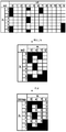
- Fig. 2 is a schematic diagram of a non-zero LC coefficient provided by an embodiment of the application.
- N3 in the first row represents the number of FD basis vectors, and 0, 1, ..., 12 in the second row represent the indices of FD basis vectors.
- 13 FD basis vectors are included.
- the 2L in the first column represents the number of SD basis vectors, and the 0, 1,..., 7 in the second column represent the indexes of the SD basis vectors.
- the gray area indicates the location where non-zero LC coefficients exist.
- frequency domain compression can be performed based on the position of non-zero LC coefficients.
- FD basis vector and SD basis vector corresponding to the position of the non-zero element (1) in the bitmap it can be determined that the non-zero LC coefficient is in In the location.
- FIG. 3 is a schematic diagram of another non-zero LC coefficient provided by an embodiment of the application.
- SC there is a strongest coefficient (SC) in the non-zero LC coefficients, including the SC polarization direction is the strong polarization direction (Pol1), and the polarization direction excluding the SC is the weak polarization direction (Pol2) ).
- FIG. 4 is a schematic flowchart of a data processing method provided by an embodiment of the application, and the execution subject in FIG. 4 may be a terminal device.
- the method may include:
- the first CSI may be information before encoding.
- the terminal device can measure the first CSI.
- the first CSI may be encoded information.
- the first CSI may include codebook information, that is, the terminal device may first measure the CSI, and then encode the measured CSI to obtain the first CSI.
- the first CSI includes non-zero LC coefficients.
- the first CSI may also include at least one of a spatial domain base indicator, a frequency domain base indicator, a strongest coefficient indicator, a reference amplitude, or a bitmap.
- S402. Determine a second CSI in the first CSI according to the first information, where the first information includes at least one of the following information: non-zero LC coefficients, frequency domain components, polarization directions, or interlayer order.
- the terminal device may perform S402 again when it is determined that the PUSCH resource allocated by the network device is less than the resource required for transmitting the first CSI.
- S402 can also be performed, so that the amount of data to be transmitted can be reduced and power consumption can be reduced.
- a frequency domain component includes a non-zero LC coefficient corresponding to a frequency domain basis vector.
- the non-zero LC coefficient in a column is a frequency domain component.
- the non-zero LC coefficient corresponding to the frequency domain basis vector index "0" (FD-basis0) is a frequency domain component
- the frequency domain basis vector index "4" (FD-basis4) corresponds to the non-zero LC coefficient
- the coefficient is a frequency domain component.
- the polarization direction includes a strong polarization direction and a weak polarization direction.
- the inter-layer sequence refers to the sequence between at least one layer selected by the terminal device.
- the second CSI is a part of the first CSI, so that the PUSCH resources required for transmitting the second CSI are less than the PUSCH resources required for transmitting the first CSI.
- the network device may determine part of the channel state information of the first CSI according to the second CSI.
- the terminal device may determine the non-zero LC coefficient to be sent among the at least one non-zero LC coefficient according to the first information.
- the non-zero LC coefficient to be sent refers to the non-zero LC coefficient to be sent by the terminal device to the network device.
- the terminal device may Delete the non-zero LC coefficients other than the non-zero LC coefficients to be transmitted from the first CSI to obtain the second CSI.
- the second CSI includes the non-zero LC coefficients to be transmitted and the non-zero LC coefficients in the first CSI. Other content.
- the terminal device may also determine the non-zero LC coefficient to be deleted among the at least one non-zero LC coefficient according to the first information.
- the non-zero LC coefficient to be deleted is the non-zero LC coefficient that the terminal device does not send to the network device.
- the device may delete the non-zero LC coefficient to be deleted in the first CSI to obtain the second CSI, and the second CSI includes other content in the first CSI except the non-zero LC coefficient to be deleted.
- the terminal device may also select a part of the content in the first CSI according to the first information as the content in the second CSI.
- the second CSI may include the remaining non-zero LC coefficients.
- the second CSI may also include at least one of a spatial domain base indicator, a frequency domain base indicator, a strongest coefficient indicator, a reference amplitude, or a bitmap. The deletion of non-zero LC coefficients by the terminal device has no effect on the spatial base indication, frequency domain base indication, strongest coefficient indication, reference amplitude or bitmap.
- the terminal device may send the second CSI, or the terminal device may also map the content in the second CSI to UCI and send the UCI to the network device.
- the terminal device may determine the second CSI in the first CSI according to the first information, and the first information includes at least one of the following information Species: non-zero LC coefficients, frequency domain components, polarization direction or inter-layer order.
- the network device can determine the channel state information reported by the terminal device according to the second CSI. Since the second CSI is a part of the first CSI, the content in the first CSI is reduced, so that the terminal device allocates it according to the network device The resources can transmit the second CSI.
- the network device After deleting part of the non-zero LC coefficients in the first CSI according to the above method to obtain the second CSI, the network device can still determine to obtain part of the channel state information according to the second CSI.
- the above method for deleting the content in the first CSI is applicable to the Rel.16 codebook.
- the content in the first information may include the following situations: Case 1.
- the first information includes: non-zero LC coefficients.
- the first information includes: non-zero LC coefficients and inter-layer order.
- the first information includes: non-zero LC coefficient and polarization direction.
- the first information includes: non-zero LC coefficient, polarization direction, and order between layers.
- FIG. 5 is a schematic flowchart of a method for determining non-zero LC coefficients to be sent according to an embodiment of the application. Referring to Figure 5, the method may include:
- the non-zero LC coefficients in each layer can be sorted first, and at least one non-zero LC coefficient can be sorted according to the layer where each non-zero LC coefficient is located and the non-zero LC coefficients in each layer after sorting .
- At least one non-zero LC coefficient can be sorted by at least the following three implementation modes:
- the first information includes at least non-zero LC coefficients.
- the non-zero LC coefficients of each layer are sorted first, and then each non-zero LC coefficient in each layer after sorting is alternately arranged.
- the first information may also include an inter-layer order, and accordingly, each non-zero LC coefficient in each sorted layer may be alternately arranged according to the inter-layer order.
- the non-zero LC coefficients can be sorted according to the index of the FD basis vector and the index of the SD basis vector corresponding to the non-zero LC coefficient. Wherein, after the non-zero LC coefficients of each layer are sorted, the indexes of the frequency domain basis vectors corresponding to the non-zero LC coefficients are sequentially increased, and the indexes of the spatial basis vectors corresponding to the non-zero LC coefficients with the same frequency domain basis vector index are sequentially increased.
- the LC coefficients of the rth layer corresponding to the lth SD basis vector and the mth FD basis vector are cr ,l,m , r ⁇ RI,l ⁇ 2L, m ⁇ M, and M is the FD selected by the user The number of basis vectors.
- the LC coefficient includes a differential amplitude indicator (p diff (l, m)) and its corresponding phase indicator.
- p diff (l, m) differential amplitude indicator
- l is sequentially increased.
- FIG. 6 is a schematic diagram of sorting non-zero LC coefficients in a layer according to an embodiment of the application. Please refer to Figure 6, according to the order of m from small to large, the non-zero LC coefficients in each column are sorted, and the non-zero LC coefficients in each column are sorted according to the index of the SD basis vector from small to large. Sort.
- the sorted non-zero LC coefficients are as follows: c 0,0,0 , c 0,2,0 , c 0,6,0 , c 0,7,0, c 0,0,4, c 0,3,4 , c 0,4,4, c 0,7,4, c 0,0,7, c 0,1,7, c 0,6,7, c 0,7,7, c 0,5,12, c 0,6,12, c 0,7,12.
- FIG. 7 is a schematic diagram of sorting non-zero LC coefficients between layers according to an embodiment of the application.
- the gray position in each row refers to the non-zero LC coefficients in a layer after sorting.
- layer 1 includes 9 sorted non-zero LC coefficients
- layer 2 includes 5 sorted non-zero LC coefficients
- layer 3 and layer 4 respectively include 4 sorted non-zero LC coefficients.
- the order of layers is: layer 1, layer 2, layer 3, and layer 4, first sort the non-zero LC coefficients in the first column.
- the sort order is shown by the arrow.
- the non-zero LC coefficients are sorted, and the sorting order is shown by the arrows, and so on, until the non-zero LC coefficients in the 9 columns in Fig. 7 are sorted.
- the non-zero LC coefficients in layer 0 include: c 0,0,2 ,c 0,1,0 ,c 0,1,1 ,c 0,2,0 ,c 0,2,3 .
- the non-zero LC coefficients in the first layer include: c 1,0,0 ,c 1,1,2 ,c 1,1,1 ,c 1,2,3 .
- the non-zero coefficients in the first After sorting the zero LC coefficients, we get: c 1,0,0 ,c 1,1,1 ,c 1,1,2 ,c 1,2,3 .
- the result is: c 0,1,0 ,c 1,0,0 c 0,2,0 ,c 1,1,1 c 0,1,1 , c 1,1,2, c 0,0,2, c 1,2,3, c 0,2,3.
- the process of sorting the non-zero LC coefficients is simple and convenient, and among the non-zero LC coefficients after sorting, the non-zero LC coefficient corresponding to the FD basis vector with the smaller index is higher.
- the first information includes at least non-zero LC coefficients.
- the non-zero LC coefficients of each layer are sorted first, and then each non-zero LC coefficient in each layer after sorting is alternately arranged.
- the first information may also include an inter-layer order, and accordingly, each non-zero LC coefficient in each sorted layer may be alternately arranged according to the inter-layer order.
- the non-zero LC coefficients can be sorted by the cyclic distance between the FD base vector corresponding to the non-zero LC coefficient and the first frequency domain base vector, and the index of the SD base vector.
- the cyclic distance S between the frequency domain basis vector corresponding to the non-zero LC coefficient and the first frequency domain basis vector increases in sequence, and the indexes of the corresponding frequency domain basis vectors are the same non-zero
- the indices of the spatial basis vectors corresponding to the LC coefficients increase sequentially.
- the priority of the non-zero LC coefficient can be determined according to the cyclic distance between the FD basis vector corresponding to the non-zero LC coefficient and the first frequency domain basis vector, and the priority of the non-zero LC coefficient and the SD basis vector The index of to sort the non-zero LC coefficients.
- the cyclic distance between the two frequency domain base vectors and the first frequency domain base vector is the same, the smaller the index of the frequency domain base vector, the higher the priority of the frequency domain base vector.
- FIG. 8 is a schematic diagram of another sorting of non-zero LC coefficients within a layer according to an embodiment of the application.
- the index and priority of each frequency domain basis vector are shown in Table 3. According to the order of priority from high to low (the value of priority is from small to large), the non-zero LC coefficients in each column For sorting, when sorting the non-zero LC coefficients in each column, sort according to the index of the SD basis vector from small to large.
- the sorted non-zero LC coefficients are as follows: c 0,0,0 , c 0,2,0 , c 0,6,0 , c 0,7,0, c 0,5,12, c 0,6,12 , c 0,7,12, c 0,0,4, c 0,3,4, c 0,4,4, c 0,7,4 , c 0,0,7 , c 0,1,7 , c 0,6,7 , c 0,7,7 .
- the method of inter-layer sorting (alternating each non-zero LC coefficient in each layer after sorting) can refer to the sorting method shown in FIG. 7, which will not be omitted here. Go ahead.
- the process of sorting the non-zero LC coefficients is simple and convenient, and among the non-zero LC coefficients after sorting, the FD basis vector whose cyclic distance between the first frequency domain basis vector is smaller corresponds to The non-zero LC coefficient is at the top.
- the first information includes at least non-zero LC coefficients and polarization directions.
- the non-zero LC coefficients of each layer are sorted first, and then each non-zero LC coefficient in each layer after sorting is alternately arranged.
- the first information may also include an inter-layer order, and accordingly, each non-zero LC coefficient in each sorted layer may be alternately arranged according to the inter-layer order.
- the non-zero LC coefficients of each layer When sorting the non-zero LC coefficients of each layer, first sort the non-zero LC coefficients in the first polarization direction in the layer, and then sort the non-zero LC coefficients in the second polarization direction in the layer.
- the non-zero LC coefficient in the first polarization direction is located before the non-zero LC coefficient in the second polarization direction.
- the indices of the frequency-domain basis vectors corresponding to the non-zero LC coefficients increase sequentially, and the corresponding frequency-domain basis vectors
- the indices of the spatial basis vectors corresponding to the non-zero LC coefficients with the same index are sequentially increased.
- the first polarization direction is a strong polarization direction
- the second polarization direction is a weak polarization direction.
- FIG. 9 is a schematic diagram of another sorting of non-zero LC coefficients within a layer according to an embodiment of the application.
- the non-zero LC coefficients in the first polarization direction are sorted first, and then the non-zero LC coefficients in the second polarization direction are sorted.
- sort the non-zero LC coefficients in the first polarization direction sort the non-zero LC coefficients of each column in the first polarization direction in the order of m from small to large, and then sort the non-zero LC coefficients in each column
- the coefficients are sorted, they are sorted according to the index of the SD basis vector from small to large.
- the sorted non-zero LC coefficients are as follows: c 0,0,0 , c 0,2,0 , c 0,0,4 , c 0,3,4, c 0,0,7, c 0,1,7 , c 0,6,0, c 0,7,0, c 0,4,4, c 0,7,4, c 0,6,7, c 0,7,7, c 0,5,12, c 0,6,12, c 0,7,12.
- the way of sorting between layers can refer to the sorting method shown in FIG. Go ahead.
- the process of sorting the non-zero LC coefficients is simple and convenient, and among the non-zero LC coefficients after sorting, the non-zero LC coefficient in the direction of strong polarization is higher.
- the first information includes at least non-zero LC coefficients and polarization directions.
- the non-zero LC coefficients of each layer are sorted first, and after the non-zero LC coefficients of each layer are sorted, each non-zero LC coefficient in each layer after sorting is alternately arranged.
- the first information may also include an inter-layer order, and accordingly, each non-zero LC coefficient in each sorted layer may be alternately arranged according to the inter-layer order.
- the non-zero LC coefficients of each layer When sorting the non-zero LC coefficients of each layer, first sort the non-zero LC coefficients in the first polarization direction in the layer, and then sort the non-zero LC coefficients in the second polarization direction in the layer.
- the non-zero LC coefficient in the first polarization direction is located before the non-zero LC coefficient in the second polarization direction.
- the priority of the frequency domain basis vectors corresponding to the non-zero LC coefficients decreases sequentially, and the corresponding frequency domain basis vectors
- the indices of the spatial basis vectors corresponding to the non-zero LC coefficients with the same priority are sequentially increased.
- the method for determining the priority of the frequency-domain basis vector in the fourth implementation manner is the same as the method for determining the priority of the frequency-domain basis vector in the second implementation manner, and will not be repeated here.
- FIG. 10 is a schematic diagram of another order of non-zero LC coefficients in a layer according to an embodiment of the application.
- the process of sorting the non-zero LC coefficients in the second polarization direction is similar to the process of sorting the non-zero LC coefficients in the first polarization direction, and will not be repeated here.
- the sorted non-zero LC coefficients are as follows: c 0,0,0 , c 0,2,0 , c 0,0,4 , c 0,3,4, c 0,0,7, c 0,1,7 , c 0,6,0, c 0,7,0, c 0,5,12, c 0,6,12, c 0,7,12, c 0,4,4, c 0,7,4, c 0,6,7, c 0,7,7.
- the way of inter-layer sorting (alternating arrangement of each non-zero LC coefficient in each layer after sorting) can refer to the sorting method shown in FIG. 7, which will not be omitted here. Go ahead.
- S502 Determine a non-zero LC coefficient to be sent according to at least one non-zero LC coefficient after sorting.
- a part of the non-zero LC coefficients in the sorted non-zero LC coefficients may be determined as the non-zero LC coefficients to be transmitted according to a preset rule.
- the number of non-zero LC coefficients to be sent (the first preset number for short) can be preset, and the first preset number of non-zero LC coefficients in the sorted non-zero LC coefficients can be determined as The non-zero LC coefficient to be sent.
- the ratio of sending non-zero LC coefficients (the first preset ratio for short) can be preset, and the first preset ratio of non-zero LC coefficients in the sorted non-zero LC coefficients can be determined as the non-zero LC coefficients to be sent.
- Zero LC coefficient For example, assuming that the first preset ratio is 0.5, the first 50% of the non-zero LC coefficients in the sorted non-zero LC coefficients may be determined as the non-zero LC coefficients to be transmitted.
- the number of non-zero LC coefficients to be transmitted in each layer is greater than or equal to the number of non-zero LC coefficients corresponding to the FD base vector with index 0 in the layer. which is, among them, Is the number of non-zero LC coefficients to be sent in the l layer, It is the number of non-zero LC coefficients corresponding to the FD basis vector (FD-basis 0) (FD component 0) with index 0 in the first layer.
- the non-zero LC coefficients in all layers are sorted first, and then a part of the ranked non-zero LC coefficients is selected as the non-zero LC coefficient to be transmitted. That is, deleting some of the non-zero LC coefficients in the lower order from the non-zero LC coefficients after sorting, and deleting a part of the non-zero LC coefficients in the lower order can not only reduce the transmission resources (PUSCH resources) required by CSI, but also As much as possible, the deleted part of the non-zero LC coefficients has less influence on the network equipment to determine the channel state information.
- PUSCH resources transmission resources
- the content in the first information may include the following situations: Case 1.
- the first information includes frequency domain components.
- the first information includes: frequency domain components and inter-layer order.
- FIG. 11 is a schematic flowchart of another method for determining non-zero LC coefficients to be sent according to an embodiment of the application.
- the method may include:
- the frequency domain components in each layer may be sorted first, and then the frequency domain components in all layers may be sorted according to the order of the frequency domain components in each layer.
- the frequency domain components can be sorted through the following feasible implementation modes:
- the first information includes at least frequency domain components.
- the frequency domain components in each layer are sorted first, and then the frequency domain components in each layer after sorting are alternately arranged.
- the first information may also include an inter-layer order, and accordingly, the frequency domain components in each layer after sorting may be alternately arranged according to the inter-layer order.
- the frequency domain components can be sorted according to the index of the frequency domain components. Among them, after sorting the frequency domain components of each layer, the indexes of the frequency domain basis vectors corresponding to the sorted frequency domain components are sequentially increased.
- the frequency domain component 1 includes 4 non-zero LC coefficients (excluding SC) in the column.
- the frequency domain component 2 contains 4 non-zero LC coefficients in the column.
- the column where m 12 is frequency domain component 4, and the frequency domain component 4 contains 3 non-zero LC coefficients in the column.
- the frequency domain components sorted in this layer are: frequency domain component 1, frequency domain component 2, frequency domain component 3, and frequency domain component 4.
- the manner of inter-layer sorting (alternating arrangement of frequency domain components in each layer after sorting) can refer to the sorting manner shown in FIG. 7, which will not be repeated here.
- the first information includes at least frequency domain components.
- the frequency domain components in each layer are sorted first, and then the frequency domain components in each layer after sorting are alternately arranged.
- the first information may also include an inter-layer order, and accordingly, the frequency domain components in each layer after sorting may be alternately arranged according to the inter-layer order.
- the frequency domain components When sorting the frequency domain components of each layer, the frequency domain components may be sorted according to the cyclic distance between the frequency domain component and the first frequency domain component. Wherein, after the frequency domain components of each layer are sorted, the cyclic distance S between the frequency domain base vector corresponding to the sorted frequency domain component and the first frequency domain base vector increases sequentially.
- the priority of the frequency domain component may be determined according to the cyclic distance between the frequency domain component and the first frequency domain component, and the frequency domain components may be sorted according to the priority of the frequency domain component. The priority is decreasing sequentially.
- cyclic distance and priority in this feasible implementation manner can refer to the cyclic distance and priority shown in the embodiment of FIG. 5, which will not be repeated here.
- the frequency domain component 1 includes 4 non-zero LC coefficients (excluding SC) in the column.
- the frequency domain component 2 contains 4 non-zero LC coefficients in the column.
- the column where m 12 is frequency domain component 4, and the frequency domain component 4 contains 3 non-zero LC coefficients in the column.
- the frequency domain components sorted in this layer are: frequency domain component 1, frequency domain component 4, frequency domain component 2 and frequency domain component 3.
- the manner of inter-layer sorting (alternating the frequency domain components in each layer after sorting) can refer to the sorting method shown in FIG. 7, and details are not described here.
- the first information includes at least frequency domain components.
- a frequency domain component group includes at least two frequency domain components.
- At least two adjacent frequency domain components may be grouped into one group.
- M frequency domain components can be divided into X frequency domain component groups, then by There are X-1 frequency domain component groups consisting of frequency domain components, and a frequency domain component group consists of Consists of several frequency domain components.
- X-1 frequency domain component groups consisting of frequency domain components
- a frequency domain component group consists of Consists of several frequency domain components.
- X can be equal to Y.
- a part of the frequency domain components in the sorted frequency domain components may be sorted according to a preset rule, and the non-zero LC coefficients in the selected part of the frequency domain components may be determined as the to-be-sent Non-zero LC coefficient.
- the non-zero LC coefficients to be transmitted can be determined in the following manner:
- the number of frequency domain components (the second preset number for short) can be preset (or pre-defined), and the first second preset number of frequency domain components in the sorted frequency domain components
- the non-zero LC coefficient is determined as the non-zero LC coefficient to be transmitted.
- a preset ratio of frequency domain components (the second preset ratio for short) may be preset, and the non-zero LC coefficients in the frequency domain components of the first second preset ratio among the sorted frequency domain components may be determined as The non-zero LC coefficient to be sent.
- the second preset ratio is 0.5
- the non-zero LC coefficients in the first 50% of the frequency-domain components after sorting may be determined as the non-zero LC coefficients to be transmitted.
- the number of frequency domain components in each layer may be the same.
- the number of frequency domain components in each layer is A, where A is greater than or equal to 1.
- the number of frequency domain components in each layer may be different.
- the number of frequency domain components in the i-th layer is A i , where A i is greater than or equal to 1.
- the non-zero LC coefficients to be transmitted can be determined in the following manner:
- the number of frequency domain component groups (or the third preset number for short) can be preset (or predefined), and the first third preset number of frequency domain components in the sorted frequency domain component groups can be set
- the non-zero LC coefficients in the group are determined as the non-zero LC coefficients to be transmitted.
- the preset ratio of the frequency domain component group (referred to as the third preset ratio) can be preset, and the first third preset ratio in the sorted frequency domain component group can be set to the non-zero LC in the frequency domain component group
- the coefficient is determined as the non-zero LC coefficient to be transmitted.
- the second preset ratio is 0.5
- the non-zero LC coefficients in the first 50% frequency-domain component groups in the sorted frequency-domain component groups may be determined as non-zero LC coefficients to be transmitted.
- the number of frequency domain component groups in each layer may be the same.
- the number of frequency domain component groups in each layer is A, where A is greater than or equal to 1.
- the number of frequency domain component groups in each layer may be different.
- the number of frequency domain component groups in the i-th layer is A i , where A i is greater than or equal to 1.
- the terminal device discards the non-zero LC coefficients in all frequency domain components outside the new window.
- bit width of each layer is
- a preset frequency domain component among the multiple frequency domain components of each layer may be determined as the non-zero LC coefficient to be sent.
- the preset frequency domain components are: frequency domain components corresponding to the first N frequency domain basis vectors sorted according to the index of the frequency domain basis vectors from small to large, and N is an integer greater than or equal to 1.
- the non-zero LC coefficient in the first frequency domain component (FD-component 0, that is, corresponding to FD basis 0) may be determined as the non-zero LC coefficient to be transmitted.
- the second CSI may not include the frequency domain base indication corresponding to the discarded frequency domain component.
- the bit width of the bitmap of each layer is 2L bits.
- the terminal device when the terminal device deletes non-zero LC coefficients in some frequency domain components, the spatial basis indication, SCI and reference amplitude are not affected.
- the bit width of each layer is or The bitmap width of each layer is 2LM rep or 2LM'.
- the frequency domain components in all layers are sorted first, and then a part of the frequency domain components (or frequency domain components) that are ranked higher in the sorted frequency domain components (or frequency domain component groups) are selected.
- the non-zero LC coefficients in the domain component group) are used as the non-zero LC coefficients to be transmitted.
- deleting some of the non-zero LC coefficients in the lower order from the non-zero LC coefficients after sorting, and deleting a part of the non-zero LC coefficients in the lower order can not only reduce the transmission resources (PUSCH resources) required by CSI, but also As much as possible, the deleted part of the non-zero LC coefficients has less influence on the network equipment to determine the channel state information.
- the first information may include the polarization direction.
- the non-zero LC coefficient in the strong polarization direction can be determined as the non-zero LC coefficient to be transmitted.
- the second CSI includes the space-based indicator, frequency-based indicator and SCI of each layer, the bit width of each layer is LM l , and the second CSI does not include the reference of each layer amplitude.
- the first information may include an order between layers.
- the non-zero LC coefficient on the preset layer may be determined as the non-zero LC coefficient to be transmitted.
- the terminal device when the terminal device determines that the PUSCH resource allocated by the network device is less than the PUSCH resource required to send the first CSI, the terminal device can use the Rel.16 Type II codebook to fall back to the Rel.15 Type II codebook for reporting , And adopt the codebook deletion rules in Rel.15. Alternatively, the terminal device can use the Rel.16 Type II codebook to fall back to the Rel.15 Type I codebook for reporting.
- FIG. 12 is a schematic structural diagram of a data processing device provided by an embodiment of this application.
- the data processing device 10 may include a processing module 11, where:
- the processing module 11 is configured to obtain first channel state information CSI;
- the processing module 11 is further configured to determine a second CSI in the first CSI according to the first information, and the first information includes at least one of the following information: non-zero LC coefficients, frequency domain components, extremes Chemical direction or order between layers.
- the data processing apparatus provided in the embodiments of the present application can execute the technical solutions shown in the foregoing method embodiments, and the implementation principles and beneficial effects are similar, and details are not described herein again.
- the first CSI includes at least one non-zero linear combined LC coefficient; the processing module 11 is specifically configured to:
- the non-zero LC coefficients other than the non-zero LC coefficients to be transmitted are deleted from the first CSI to obtain the second CSI.
- the first information is a non-zero LC coefficient
- the processing module 11 is specifically configured to:
- processing module 11 is specifically configured to:
- the at least one non-zero LC coefficient is sorted according to the layer where each of the non-zero LC coefficients is located and the non-zero LC coefficient in each sorted layer.
- the indices of the frequency-domain basis vectors corresponding to the non-zero LC coefficients are successively increased, and the indices of the frequency-domain basis vectors corresponding to the non-zero LC coefficients are the same
- the index of the spatial basis vector increases sequentially.
- the cyclic distance S between the frequency domain basis vector corresponding to the non-zero LC coefficient and the first frequency domain basis vector increases in sequence, and the corresponding frequency domain
- the indexes of the spatial basis vectors corresponding to the non-zero LC coefficients with the same index of the basis vectors increase sequentially;
- the non-zero LC coefficient in the first polarization direction is located before the non-zero LC coefficient in the second polarization direction;
- the indices of the frequency-domain basis vectors corresponding to the non-zero LC coefficients increase sequentially, and the corresponding non-zero LCs with the same index of the frequency-domain basis vectors
- the indices of the spatial basis vectors corresponding to the coefficients increase sequentially.
- the first polarization direction is a strong polarization direction
- the second polarization direction is a weak polarization direction
- processing module 11 is specifically configured to:
- each non-zero LC coefficient in each layer after sorting is alternately arranged.
- the number of non-zero LC coefficients in the i-th layer is greater than or equal to the non-zero LC coefficients in the i-th layer corresponding to the first frequency domain basis vector
- the first frequency domain basis vector is a frequency domain basis vector with an index of 0.
- the first information is a frequency domain component; the processing module 11 is specifically configured to:
- the non-zero LC coefficients to be transmitted are determined.
- processing module 11 is specifically configured to:
- the frequency domain components sorted in each layer are sorted.
- processing module 11 is specifically configured to:
- a frequency domain component group includes at least two frequency domain components, and the at least one non-zero LC coefficient corresponds to a total of B Frequency domain component group, where B is an integer greater than 2;
- the indexes of the frequency domain basis vectors corresponding to the sorted frequency domain components are sequentially increased.
- the cyclic distance S between the frequency domain base vector corresponding to the sorted frequency domain component and the first frequency domain base vector increases sequentially
- the number of frequency domain components in each layer is A, where A is greater than or equal to 1, or, A is a predefined .
- the number of frequency domain components in the i-th layer is A i , where the A i is greater than or equal to 1, or the A i is pre-defined.
- the number of frequency domain component groups in each layer is A, where A is greater than or equal to 1, or, A is a predefined of.
- the first information is a frequency domain component; the processing module 11 is specifically configured to:
- a preset frequency domain component among the multiple frequency domain components of each layer is determined as the non-zero LC coefficient to be transmitted.
- the preset frequency domain components are: frequency domain components corresponding to the first N frequency domain basis vectors sorted according to the index of the frequency domain basis vector from small to large, where N is greater than or An integer equal to 1.
- the first information is a polarization direction; the processing module 11 is specifically configured to:
- the non-zero LC coefficient in the strong polarization direction is determined as the non-zero LC coefficient to be transmitted.
- the second CSI further includes at least one of a spatial domain base indicator, a frequency domain base indicator, a strongest coefficient indicator, a reference amplitude, or a bitmap.
- FIG. 13 is a schematic structural diagram of another data processing device provided by an embodiment of the application. Based on the embodiment shown in FIG. 12, referring to FIG. 13, the data processing device 10 further includes a sending module 12, where:
- the sending module 12 is configured to send the second CSI to the network device after the processing module 11 determines the second CSI in the first CSI according to the first information;
- the sending module 12 is configured to, after the processing module 11 determines the second CSI in the first CSI according to the first information, map the second CSI to the uplink control information UCI, and send it to the network The device sends the UCI.
- the data processing apparatus provided in the embodiments of the present application can execute the technical solutions shown in the foregoing method embodiments, and the implementation principles and beneficial effects are similar, and details are not described herein again.
- FIG. 14 is a schematic structural diagram of a terminal device provided by an embodiment of the application.
- the terminal device 20 may include: a transceiver 21, a memory 22, and a processor 23.
- the transceiver 21 may include a transmitter and/or a receiver.
- the transmitter can also be referred to as a transmitter, a transmitter, a transmitting port, or a transmitting interface
- the receiver can also be referred to as a receiver, a receiver, a receiving port, or a receiving interface, and similar descriptions.
- the transceiver 21, the memory 22, and the processor 23 are connected to each other through a bus 24.
- the memory 22 is used to store program instructions
- the processor 23 is configured to execute the program instructions stored in the memory, so as to enable the terminal device 20 to execute any of the data processing methods shown above.
- the receiver of the transceiver 21 can be used to perform the receiving function of the terminal device in the above data processing method.
- An embodiment of the present application provides a computer-readable storage medium that stores a computer-executable instruction, and when the computer-executable instruction is executed by a processor, it is used to implement the aforementioned data processing method.
- the embodiments of the present application may also provide a computer program product, which can be executed by a processor, and when the computer program product is executed, it can implement the data processing method executed by any of the above-mentioned terminal devices.
- the terminal device, computer-readable storage medium, and computer program product of the embodiments of the present application can execute the data processing method executed by the above-mentioned terminal device.
- the specific implementation process and beneficial effects refer to the above, and will not be repeated here.
- the disclosed system, device, and method may be implemented in other ways.
- the device embodiments described above are only illustrative.
- the division of the units is only a logical function division, and there may be other divisions in actual implementation, for example, multiple units or components can be combined or It can be integrated into another system, or some features can be ignored or not implemented.
- the displayed or discussed mutual coupling or direct coupling or communication connection may be indirect coupling or communication connection through some interfaces, devices or units, and may be in electrical, mechanical or other forms.
- the units described as separate components may or may not be physically separated, and the components displayed as units may or may not be physical units, that is, they may be located in one place, or they may be distributed on multiple network units. Some or all of the units may be selected according to actual needs to achieve the objectives of the solutions of the embodiments.
- each unit in each embodiment of the present application may be integrated into one processing unit, or each unit may exist alone physically, or two or more units may be integrated into one unit.
- the above-mentioned integrated unit can be implemented in the form of hardware or software functional unit.
- the aforementioned computer program can be stored in a computer readable storage medium.
- the computer program When the computer program is executed by the processor, it realizes the steps including the foregoing method embodiments; and the foregoing storage medium includes: ROM, RAM, magnetic disk, or optical disk and other media that can store program codes.
Abstract
Des modes de réalisation de la présente invention concernent un procédé, un appareil et un dispositif de traitement de données, et un support de stockage. Le procédé consiste à : obtenir des premières informations d'état de canal (CSI) ; d'après des premières informations, déterminer des secondes CSI dans les premières CSI, les premières informations comprenant au moins l'une des informations suivantes : un coefficient LC non nul, une composante de domaine fréquentiel, une direction de polarisation ou une séquence intercouche. Le procédé est apte à supprimer une partie du contenu de CSI dans un livre de codes Rel-16.
Priority Applications (8)
| Application Number | Priority Date | Filing Date | Title |
|---|---|---|---|
| PCT/CN2019/092841 WO2020258043A1 (fr) | 2019-06-25 | 2019-06-25 | Procédé, appareil et dispositif de traitement de données, et support de stockage |
| CN202210122337.4A CN114499811B (zh) | 2019-06-25 | 2019-09-05 | 数据处理方法、装置、设备及存储介质 |
| CN201980094356.7A CN113678390A (zh) | 2019-06-25 | 2019-09-05 | 数据处理方法、装置、设备及存储介质 |
| PCT/CN2019/104594 WO2020258518A1 (fr) | 2019-06-25 | 2019-09-05 | Procédé de traitement de données, dispositif, appareil et support d'informations |
| KR1020217042984A KR20220024200A (ko) | 2019-06-25 | 2019-09-05 | 데이터 처리 방법, 장치, 디바이스 및 기록 매체 |
| JP2021577845A JP2022551787A (ja) | 2019-06-25 | 2019-09-05 | データ処理方法、装置、デバイス、および記録媒体 |
| EP19935410.1A EP3985898B1 (fr) | 2019-06-25 | 2019-09-05 | Procédé de traitement de données, dispositif, appareil et support d'informations |
| US17/558,939 US20220116091A1 (en) | 2019-06-25 | 2021-12-22 | Data processing method, device, apparatus, and storage medium |
Applications Claiming Priority (1)
| Application Number | Priority Date | Filing Date | Title |
|---|---|---|---|
| PCT/CN2019/092841 WO2020258043A1 (fr) | 2019-06-25 | 2019-06-25 | Procédé, appareil et dispositif de traitement de données, et support de stockage |
Publications (1)
| Publication Number | Publication Date |
|---|---|
| WO2020258043A1 true WO2020258043A1 (fr) | 2020-12-30 |
Family
ID=74059869
Family Applications (2)
| Application Number | Title | Priority Date | Filing Date |
|---|---|---|---|
| PCT/CN2019/092841 WO2020258043A1 (fr) | 2019-06-25 | 2019-06-25 | Procédé, appareil et dispositif de traitement de données, et support de stockage |
| PCT/CN2019/104594 WO2020258518A1 (fr) | 2019-06-25 | 2019-09-05 | Procédé de traitement de données, dispositif, appareil et support d'informations |
Family Applications After (1)
| Application Number | Title | Priority Date | Filing Date |
|---|---|---|---|
| PCT/CN2019/104594 WO2020258518A1 (fr) | 2019-06-25 | 2019-09-05 | Procédé de traitement de données, dispositif, appareil et support d'informations |
Country Status (6)
| Country | Link |
|---|---|
| US (1) | US20220116091A1 (fr) |
| EP (1) | EP3985898B1 (fr) |
| JP (1) | JP2022551787A (fr) |
| KR (1) | KR20220024200A (fr) |
| CN (2) | CN114499811B (fr) |
| WO (2) | WO2020258043A1 (fr) |
Families Citing this family (1)
| Publication number | Priority date | Publication date | Assignee | Title |
|---|---|---|---|---|
| CN116961856A (zh) * | 2022-04-25 | 2023-10-27 | 展讯通信(上海)有限公司 | 一种数据处理方法、芯片和电子设备 |
Family Cites Families (9)
| Publication number | Priority date | Publication date | Assignee | Title |
|---|---|---|---|---|
| CN105429683B (zh) * | 2014-09-17 | 2019-08-20 | 上海朗帛通信技术有限公司 | 一种3d mimo传输方法和装置 |
| US10009088B2 (en) * | 2016-03-28 | 2018-06-26 | Samsung Electronics Co., Ltd. | Linear combination PMI codebook based CSI reporting in advanced wireless communication systems |
| CN107529691B (zh) * | 2016-06-22 | 2020-11-06 | 上海朗帛通信技术有限公司 | 一种无线通信中的方法和装置 |
| CN107682054B (zh) * | 2016-08-02 | 2022-05-17 | 大唐移动通信设备有限公司 | 一种信道状态信息反馈方法及相关设备 |
| CN109150412B (zh) * | 2017-06-16 | 2021-10-29 | 上海朗帛通信技术有限公司 | 一种被用于无线通信的用户、基站中的方法和装置 |
| WO2019034121A1 (fr) * | 2017-08-16 | 2019-02-21 | Nokia Shanghai Bell Co., Ltd. | Procédé, dispositif et support lisible par ordinateur destinés à une communication mimo |
| CN109510654B (zh) * | 2017-09-14 | 2023-05-02 | 大唐移动通信设备有限公司 | 一种信道状态信息反馈方法及装置 |
| US11128362B2 (en) * | 2019-03-11 | 2021-09-21 | Samsung Electronics Co., Ltd. | Method and apparatus for multiplexing and omitting channel state information |
| EP3963736A1 (fr) * | 2019-05-03 | 2022-03-09 | Telefonaktiebolaget Lm Ericsson (Publ) | Règles d'omission de csi permettant un bilan de csi de type ii amélioré |
-
2019
- 2019-06-25 WO PCT/CN2019/092841 patent/WO2020258043A1/fr active Application Filing
- 2019-09-05 EP EP19935410.1A patent/EP3985898B1/fr active Active
- 2019-09-05 JP JP2021577845A patent/JP2022551787A/ja active Pending
- 2019-09-05 KR KR1020217042984A patent/KR20220024200A/ko unknown
- 2019-09-05 WO PCT/CN2019/104594 patent/WO2020258518A1/fr unknown
- 2019-09-05 CN CN202210122337.4A patent/CN114499811B/zh active Active
- 2019-09-05 CN CN201980094356.7A patent/CN113678390A/zh active Pending
-
2021
- 2021-12-22 US US17/558,939 patent/US20220116091A1/en active Pending
Non-Patent Citations (3)
| Title |
|---|
| ERICSSON: "R1-1907076, On CSI omission procedure,", 3GPP TSG RAN WG1 MEETING RAN1#97,, 3 May 2019 (2019-05-03), XP051709105, DOI: 20200309104121X * |
| SAMSUNG: "R1-1806714, Issues on CSI reporting,", 3GPP TSG RAN WG1 MEETING #93, 11 May 2018 (2018-05-11), XP051461923, DOI: 20200309103851X * |
| VIVO: "R1-1904095, Further discussion on type II CSI compression and feedback for high", 3GPP TSG RAN WG1#96BIS,, 30 March 2019 (2019-03-30), XP051699473, DOI: 20200309104003X * |
Also Published As
| Publication number | Publication date |
|---|---|
| WO2020258518A1 (fr) | 2020-12-30 |
| CN113678390A (zh) | 2021-11-19 |
| KR20220024200A (ko) | 2022-03-03 |
| EP3985898A4 (fr) | 2022-08-10 |
| US20220116091A1 (en) | 2022-04-14 |
| CN114499811A (zh) | 2022-05-13 |
| EP3985898B1 (fr) | 2024-04-17 |
| EP3985898A1 (fr) | 2022-04-20 |
| CN114499811B (zh) | 2023-08-15 |
| JP2022551787A (ja) | 2022-12-14 |
Similar Documents
| Publication | Publication Date | Title |
|---|---|---|
| WO2020125655A1 (fr) | Procédé et dispositif de communication | |
| WO2018153307A1 (fr) | Procédé et dispositif de transmission de données | |
| CN105075138B (zh) | 确定预编码矩阵指示的方法、用户设备和基站 | |
| US11431384B2 (en) | Channel estimation method and apparatus | |
| US11418244B2 (en) | CSI feedback with type-II codebook compression | |
| WO2022002079A1 (fr) | Procédé et appareil de détermination de matrice de précodage | |
| CN111756417B (zh) | 一种信道状态信息反馈方法及装置 | |
| WO2021004193A1 (fr) | Procédé et appareil de renvoi d'informations de capacité, et procédé et appareil de renvoi d'informations d'état de canal | |
| CN111416645B (zh) | 预编码矩阵指示方法及相关设备 | |
| CN113114410A (zh) | 数据处理方法、配置方法及通信设备 | |
| WO2020083057A1 (fr) | Procédé d'indication et de détermination d'un vecteur de précodage et appareil de communication | |
| CN114696928A (zh) | 一种干扰测量方法、用户终端和网络侧设备 | |
| EP4290816A2 (fr) | Procédé et appareil d'estimation de canal | |
| US20240097753A1 (en) | Determining a precoder for wireless communications | |
| JP2023082207A (ja) | チャネル状態情報を送受信するための方法、端末装置およびネットワーク装置 | |
| WO2020258043A1 (fr) | Procédé, appareil et dispositif de traitement de données, et support de stockage | |
| CN111628844B (zh) | 一种信道状态信息反馈方法及装置 | |
| CN111587543B (zh) | 信道状态信息矩阵信息处理方法及通信装置 | |
| EP4092922B1 (fr) | Précodage d'informations | |
| WO2023274101A1 (fr) | Procédé et appareil pour obtenir une matrice de précodage | |
| WO2023202717A1 (fr) | Procédé de transmission de données de liaison montante et dispositif terminal | |
| CN115333582B (zh) | 预编码信息 | |
| TWI784462B (zh) | 上行功率、調度資訊確定方法、終端和網路側設備 | |
| WO2022257042A1 (fr) | Procédé de création de rapport de livre de codes, dispositif terminal et dispositif de réseau | |
| WO2023125049A1 (fr) | Procédé et appareil de rétroaction d'informations d'état de canal, support et produit-programme |
Legal Events
| Date | Code | Title | Description |
|---|---|---|---|
| 121 | Ep: the epo has been informed by wipo that ep was designated in this application |
Ref document number: 19934820 Country of ref document: EP Kind code of ref document: A1 |
|
| NENP | Non-entry into the national phase |
Ref country code: DE |
|
| 122 | Ep: pct application non-entry in european phase |
Ref document number: 19934820 Country of ref document: EP Kind code of ref document: A1 |