WO2020255753A1 - 分離デバイス及び分離方法 - Google Patents
分離デバイス及び分離方法 Download PDFInfo
- Publication number
- WO2020255753A1 WO2020255753A1 PCT/JP2020/022295 JP2020022295W WO2020255753A1 WO 2020255753 A1 WO2020255753 A1 WO 2020255753A1 JP 2020022295 W JP2020022295 W JP 2020022295W WO 2020255753 A1 WO2020255753 A1 WO 2020255753A1
- Authority
- WO
- WIPO (PCT)
- Prior art keywords
- flow path
- separation
- cross
- sectional area
- recovery
- Prior art date
- Legal status (The legal status is an assumption and is not a legal conclusion. Google has not performed a legal analysis and makes no representation as to the accuracy of the status listed.)
- Ceased
Links
Images


Classifications
-
- C—CHEMISTRY; METALLURGY
- C12—BIOCHEMISTRY; BEER; SPIRITS; WINE; VINEGAR; MICROBIOLOGY; ENZYMOLOGY; MUTATION OR GENETIC ENGINEERING
- C12M—APPARATUS FOR ENZYMOLOGY OR MICROBIOLOGY; APPARATUS FOR CULTURING MICROORGANISMS FOR PRODUCING BIOMASS, FOR GROWING CELLS OR FOR OBTAINING FERMENTATION OR METABOLIC PRODUCTS, i.e. BIOREACTORS OR FERMENTERS
- C12M1/00—Apparatus for enzymology or microbiology
-
- C—CHEMISTRY; METALLURGY
- C12—BIOCHEMISTRY; BEER; SPIRITS; WINE; VINEGAR; MICROBIOLOGY; ENZYMOLOGY; MUTATION OR GENETIC ENGINEERING
- C12M—APPARATUS FOR ENZYMOLOGY OR MICROBIOLOGY; APPARATUS FOR CULTURING MICROORGANISMS FOR PRODUCING BIOMASS, FOR GROWING CELLS OR FOR OBTAINING FERMENTATION OR METABOLIC PRODUCTS, i.e. BIOREACTORS OR FERMENTERS
- C12M1/00—Apparatus for enzymology or microbiology
- C12M1/26—Inoculator or sampler
-
- G—PHYSICS
- G01—MEASURING; TESTING
- G01N—INVESTIGATING OR ANALYSING MATERIALS BY DETERMINING THEIR CHEMICAL OR PHYSICAL PROPERTIES
- G01N1/00—Sampling; Preparing specimens for investigation
- G01N1/02—Devices for withdrawing samples
- G01N1/04—Devices for withdrawing samples in the solid state, e.g. by cutting
Definitions
- the present invention relates to a separation device and a separation method.
- the present application claims priority with respect to Japanese Patent Application No. 2019-115558 filed in Japan on June 21, 2019, the contents of which are incorporated herein by reference.
- the deterministic lateral displacement is a method in which large particles are placed around the pillars when a laminar flow of fluid containing particles is passed through an array of minute pillars arranged with slight displacement. While the small particles flow diagonally due to the change in the flow that occurs, the small particles are a method of separating the particles according to their size by utilizing the property of traveling linearly on the laminar flow (see, for example, Non-Patent Document 1). ).
- Patent Document 1 describes a method for separating cells using the principle of DLD.
- an object of the present invention is to provide a technique for accurately separating target particles in a fluid sample.
- a separation device for separating the target particles from a fluid sample containing target particles having a size equal to or larger than the threshold value and non-target particles having a size smaller than the threshold value, and separating the particles in the fluid according to the size.
- the separation flow path is connected to the upstream side of the separation flow path, the fluid introduction section for introducing the fluid sample and the buffer into the separation flow path, and the target particle connected to the downstream side of the separation flow path. It has a recovery unit for collecting the fluid containing the fluid and the fluid containing the non-target particles, respectively, and the fluid introduction unit is connected to a first introduction port for introducing the buffer and the first introduction port.
- a first flow path through which the fluid flows a first branch portion that branches the first flow path into a first bypass flow path and a second bypass flow path, and a downstream side of the first branch portion.
- a second inlet for introducing the fluid sample a second flow path connected to the second inlet and for flowing the fluid sample, the first bypass flow path, and the second.
- the cross-sectional area b on the plane perpendicular to the flow direction of the second bypass flow path at the confluence part satisfies the following formula (1), and the recovery part is the first one through which the fluid containing the non-target particles flows. It has a recovery flow path and a second recovery flow path through which a fluid containing the target particles flows, and the first recovery flow path is connected to the first bypass flow path side of the separation flow path.
- the separation device in which the second recovery flow path is connected to the second bypass flow path side of the separation flow path (A / B) ⁇ (a / b) ... (1) [2] The separation device according to [1], wherein the cross-sectional area a and the cross-sectional area b satisfy the following formula (2). a ⁇ b ... (2) [3]
- the recovery section has a second branch section that branches the separation flow path into a first recovery flow path and a second recovery flow path, and the first recovery section in the second branch section.
- the cross-sectional area ⁇ on the plane perpendicular to the flow direction of the flow path and the cross-sectional area ⁇ on the plane perpendicular to the flow direction of the second recovery flow path at the second branch portion satisfy the following equation (3).
- the cross-sectional area of the confluence portion on the plane perpendicular to the flow direction of the second flow path is 5 to 30% of the cross-sectional area of the plane perpendicular to the flow direction of the separation flow path [1].
- the separation device according to any one of [3].
- [6] A method for separating the target particles from the fluid sample containing the target particles having a size equal to or larger than the threshold value and the non-target particles having a size smaller than the threshold value, [1] to [5].
- the buffer is introduced from the first introduction port of the separation device according to any one of the above, the fluid sample is introduced from the second introduction port, and the fluid containing the target particles or the said from the recovery unit.
- a method comprising recovering a fluid containing non-target particles.
- FIG. 3 is a cross-sectional view taken along the line bb'of FIG. 1A. It is a figure explaining the basic principle of the deterministic transverse substitution method (DLD). It is a figure which shows the simulation result in Experimental Example 1.
- FIG. It is a graph which shows the moving distance of the laminar flow of a fluid sample calculated by the simulation in Experimental Example 1. In Experimental Example 2, it is a photograph which photographed the head part, the middle part, and the tail part of the separation flow path of a separation device.
- the present invention is a separation device that separates the target particles from a fluid sample containing a target particle having a size equal to or more than a threshold value and a non-target particle having a size less than the threshold value, and is in a fluid.
- a separation flow path that separates particles according to size, a fluid introduction section that is connected to the upstream side of the separation flow path and introduces the fluid sample and buffer into the separation flow path, and a downstream side of the separation flow path.
- the fluid introduction unit has a first introduction port for introducing the buffer and the first introduction unit, which has a recovery unit for collecting the fluid containing the target particles and the fluid containing the non-target particles, respectively.
- a first flow path connected to an introduction port and through which the buffer flows, a first branch portion that branches the first flow path into a first bypass flow path and a second bypass flow path, and the first branch portion.
- the cross-sectional area a in the above and the cross-sectional area b in the plane perpendicular to the flow direction of the second bypass flow path at the confluence satisfy the following formula (1), and the recovery unit contains the non-target particles. It has a first recovery flow path through which a fluid flows and a second recovery flow path through which a fluid containing the target particles flows, and the first recovery flow path is the first bypass flow of the separation flow path.
- the second recovery flow path which is connected to the roadside, provides a separation device which is connected to the second bypass flow path side of the separation flow path.
- FIG. 1A is a top view illustrating the structure of the separation device of the present embodiment.
- the arrows indicate the direction in which the fluid flows.
- FIG. 1B is a cross-sectional view taken along the line bb'of FIG. 1A.
- the separation device 100 includes a separation flow path 110, a fluid introduction unit 120, and a recovery unit 130.
- the fluid introduction unit 120 is connected to the upstream side of the separation flow path 110, and introduces the fluid sample and the buffer into the separation flow path 110.
- the recovery unit 130 is connected to the downstream side of the separation flow path 110, and recovers the fluid containing the target particles and the fluid containing the non-target particles, respectively.
- the fluid introduction section 120 includes a first introduction port 121, a first flow path 122, a first branch section 123, a second introduction port 124, a second flow path 125, and a confluence section 126.
- the buffer is introduced from the first introduction port 121.
- the first flow path 122 is connected to the first introduction port 121, and the buffer flows in the first flow path 122.
- the first branch portion 123 branches the first flow path 122 into the first bypass flow path 1221 and the second bypass flow path 1222.
- the second introduction port 124 is located on the downstream side of the first branch portion 123.
- the fluid sample is introduced from the second introduction port 124.
- the second flow path 125 is connected to the second introduction port 124, and the fluid sample flows in the second flow path 125.
- the first bypass flow path 1221, the second flow path 125, and the second bypass flow path 1222 merge at the merging portion 126.
- the recovery unit 130 has a first recovery flow path 131 through which a fluid containing non-target particles flows, and a second recovery flow path 132 through which a fluid containing target particles flows.
- the first recovery flow path 131 is connected to the first bypass flow path 1221 side in a direction perpendicular to the flow direction of the separation flow path 110. That is, the first recovery flow path 131 is arranged closer to the first bypass flow path 1221 than the second bypass flow path 1222 in the direction perpendicular to the flow direction of the separation flow path 110.
- the second recovery flow path 132 is connected to the second bypass flow path 1222 side in a direction perpendicular to the flow direction of the separation flow path 110.
- the second recovery flow path 132 is arranged closer to the second bypass flow path 1222 than the first bypass flow path 1221 in the direction perpendicular to the flow direction of the separation flow path 110. Further, the first recovery flow path 131 is connected to the discharge port 134. The second recovery flow path 132 is connected to the discharge port 135.
- the velocity of the fluid discharged from the second bypass flow path 1222 to the separation flow path 110 is the velocity of the fluid discharged from the first bypass flow path 1221 to the separation flow path 110. It is considered that the speed is the same as or higher than the speed of the fluid discharged from the first bypass flow path 1221 to the separation flow path 110.
- the laminar flow formed by the fluid sample merged from the second flow path 125 becomes difficult to flow to the second bypass flow path 1222 side, that is, the second recovery flow path 132 side. That is, the fluid sample is less likely to be mixed into the second recovery flow path 132 in which the target particles are recovered, and the target particles can be recovered with high accuracy.
- the ability to accurately recover the target particles means that the target particles have a high separation ability.
- the separation device of this embodiment can accurately separate the target particles in the fluid sample.
- the cross-sectional areas A and B refer to the cross-sectional areas of the branch portion 123 at the positions where the first flow path branches to the first bypass flow path 1221 and the second bypass flow path for the first time.
- the cross-sectional areas A and B are the upstream ends of the partition wall 1223 for branching the first flow path 122 into the first bypass flow path 1221 and the second bypass flow path 1222 in the branch portion 123. It is the cross-sectional area in the part.
- the cross-sectional areas a and b refer to the cross-sectional areas at the positions where the first bypass flow path 1221 and the second bypass flow path 1222 meet for the first time in the merging portion 126.
- the cross-sectional areas a and b are the cross-sectional areas at the downstream end of the partition wall 1223.
- the collection unit 130 has a second branch unit 133 that branches the separation flow path 110 into the first collection flow path 131 and the second collection flow path 132.
- the principle of separation in the separation flow path 110 is not particularly limited as long as it is a separation method for forming a laminar flow.
- it may be a deterministic transverse substitution method (hereinafter, may be referred to as DLD), separation by size, separation by magnetism, or the like.
- DLD deterministic transverse substitution method
- the principle of separation in the separation flow path 110 is DLD. DLD will be described later.
- the buffer introduced from the first introduction port 121 and the fluid sample introduced from the second introduction port 124 form a laminar flow on the downstream side of the confluence portion 126.
- This laminar flow passes through an array of tiny pillars 111 formed inside the separation channel 110.
- particles having a size equal to or larger than the threshold value flow diagonally in the direction toward the bypass flow path 1222.
- the collection unit 130 passes through the second collection flow path 132 and is collected from the discharge port 135.
- particles having a size less than the threshold value travel linearly on the laminar flow.
- the collection unit 130 passes through the first collection flow path 131 and is collected from the discharge port 134.
- the buffer and the fluid sample can be fed by, for example, a syringe pump, a diaphragm pump, a roller tube pump, or the like.
- the cross-sectional area a and the cross-sectional area b preferably satisfy the following formula (2). a ⁇ b ... (2)
- the cross-sectional area a and the cross-sectional area b satisfy the above equation (2) means that if the heights of the first bypass flow path 1221 and the second bypass flow path 1222 in the merging portion 126 are constant, they merge. It means that the opening of the second flow path 125 in the portion 126 is located at the center in the width direction (direction perpendicular to the fluid flow direction) of the separation flow path 110 or on the side of the first bypass flow path 1221. That is, it means that the opening of the second flow path 125 in the merging portion 126 is located at the center in the width direction of the separation flow path 110 or closer to the first bypass flow path 1221 than the second bypass flow path 1222. .. Generally, the height of each flow path constituting the separation device is constant.
- the laminar flow of the fluid sample moves to the first bypass flow path side, and the fluid sample is easily collected in the first recovery flow path 131 in the recovery unit 130. Therefore, the fluid sample is less likely to be mixed into the second recovery flow path 132 in which the target particles are recovered, and the target particles can be recovered with high accuracy.
- the ratio of the cross-sectional area a to the cross-sectional area b is preferably 0.05 or more and 0.8 or less, more preferably 0.08 or more and 0.75 or less, and 0.1 or more and 0. It is more preferably 0.7 or less, and further preferably 0.15 or more and 0.65 or less.
- a / b is 0.05 or more and 0.8 or less, it becomes easy to control the laminar flow of the fluid sample to move to the first bypass flow path side. As a result, the fluid sample is easily collected in the first collection flow path 131 in the collection unit 130.
- the fluid sample is less likely to be mixed into the second recovery flow path 132 in which the target particles are recovered, and the target particles can be recovered with high accuracy.
- the cross-sectional area ⁇ in the plane perpendicular to the flow direction of the first recovery flow path 131 in the second branch portion 133 and the second recovery flow path 132 in the second branch portion 133 preferably satisfies the following equation (3). (A / b) ⁇ ( ⁇ / ⁇ ) ... (3)
- the cross-sectional areas ⁇ and ⁇ refer to the cross-sectional areas at the positions where the separation flow path 110 first branches into the first recovery flow path 131 and the second recovery flow path 132 in the branch portion 133.
- the fact that the cross-sectional areas a, b, ⁇ , and ⁇ satisfy the above equation (3) is more than the ratio of the width of the first bypass flow path 1221 to the width of the second bypass flow path 1222 at the merging portion 126. It means that the ratio of the width of the first recovery flow path 131 to the width of the second recovery flow path 132 in the merging portion 133 is larger.
- the fluid sample is easily collected in the first collection flow path 131 in the collection unit 130. Therefore, the fluid sample is less likely to be mixed into the second recovery flow path 132 in which the target particles are recovered, and the target particles can be recovered with high accuracy.
- ⁇ may have a size of ⁇ or more regardless of the sizes of the cross-sectional areas a and b. That is, it is preferable that ⁇ and ⁇ satisfy the following formula (4). ⁇ ⁇ ⁇ ... (4)
- the cross-sectional area C of the merging portion 126 on the plane perpendicular to the flow direction of the second flow path 125 is 5 with respect to the cross-sectional area D on the plane perpendicular to the flow direction of the separation flow path 110. It is preferably about 30%.
- the fluid sample can be reliably recovered in the first recovery flow path 131 in the recovery unit 130.
- the larger the cross-sectional area C the larger the volume of the fluid sample that can be introduced into the separation device per unit time, and the faster the processing speed for separating the target particles can be improved.
- the cross-sectional area D of the separation flow path 110 is not constant, the average value of the cross-sectional areas on the plane perpendicular to the flow direction of the separation flow path 110 may be set as the cross-sectional area D.
- the average value of the cross-sectional areas on the plane perpendicular to the flow direction of the separation flow path 110 in the present specification is calculated by the following method. Ten points between the smallest cross-sectional area and the largest cross-sectional area in the plane perpendicular to the flow direction of the separation flow path 110 are selected at equal intervals, and the respective cross-sectional areas are measured. The sum of the cross-sectional area values of 10 points is taken as the measurement point, that is, the value divided by 10 is taken as the average value.
- examples of particles to be separated include beads, cells, and the like.
- the beads may be those in which a specific binding substance that specifically recognizes a target protein or the like is bound to the surface thereof.
- Specific binding substances include antibodies, antibody fragments, aptamers and the like.
- the material of the beads is not particularly limited, and examples thereof include silica, polystyrene, latex, and metal.
- the beads may be magnetic particles.
- the target protein or the like in the fluid sample can be bound to the beads. Further, by recovering the beads with the separation device described above, the target protein or the like in the fluid sample can be recovered.
- the cell or the exosome or the like is bound to the bead. Can be done. Then, by recovering such beads with the separation device described above, specific cells, exosomes, etc. in the fluid sample can be recovered.
- the cell is not particularly limited, and examples thereof include any cell expressing a specific marker protein on the cell surface.
- the cell may be, for example, a circulating tumor cell in blood (hereinafter, may be referred to as CTC).
- the size of the target cell and the size of the non-target cell are similar, it may be difficult to separate the two.
- beads of an appropriate size are specifically bound only to the target cells to make the target cells apparently large particles, thereby increasing the size difference from the non-target cells and separating the device. Can be easily separated with.
- the size of the particle when the particle is a sphere, the size of the particle may be the diameter of the sphere.
- the particle when the particle is not a sphere, a sphere having the same volume as the particle may be assumed, and the diameter of the sphere may be the size of the particle.
- DLD is small when a laminar flow of fluid containing particles is passed through an array of minute pillars arranged with a slight shift, while large particles flow diagonally due to changes in the flow that occur around the pillars.
- Particles are a method of separating particles according to their size by utilizing the property of traveling linearly on a laminar flow.
- the threshold value (Dc) of the particle diameter displaced in the oblique direction can be set according to the particle size of the particles to be separated, that is, the target particles. More specifically, the setting of the threshold value Dc can be obtained from the following equation (5).
- Dc 2 ⁇ G ⁇ ... (5)
- ⁇ is a variable
- G is the gap between pillars
- ⁇ the deviation angle of pillars (tan ⁇ ).
- the inter-pillar gap G is calculated based on the threshold value Dc of the particle diameter displaced in the oblique direction. Then, from the above equation (7), the inter-pillar gap G is calculated based on the threshold value Dc of the particle diameter displaced in the oblique direction. Then, a cell separation device having a basic structural portion in which the pillar group of the inter-pillar gap G (hereinafter, may be referred to as an obstacle structure) is installed can be produced. In this way, a separation device having a DLD microchannel having a desired threshold Dc can be made.
- FIG. 2 is a diagram illustrating the basic principle of the deterministic transverse substitution method (DLD).
- FIG. 2 shows the basic structure 20 of the DLD microchannel (hereinafter, may be referred to as a separation area).
- an obstacle structure hereinafter, may be referred to as a pillar 21 arranged diagonally according to a certain rule with respect to the flow direction of the fluid in the direction of the arrow is provided.
- the flow velocity changes around the obstacle structure 21.
- the particles 22 having a size equal to or larger than the threshold value are displaced in the oblique direction according to the arrangement of the obstacle structures 21 arranged continuously.
- the particles 23 having a size less than the threshold value generally travel straight along the flow direction while bypassing the obstacle structure 21.
- Non-Patent Document 1 a known method
- the target contained in the fluid It can be separated depending on the size of the particles.
- the separated particles can be recovered respectively.
- the shape of the obstacle structure 21 is not limited to the cylindrical structure as shown in FIG.
- the obstacle structure 21 may have a polygonal prism structure such as a triangular prism or a quadrangular prism as long as it has a shape capable of causing a desired change in flow velocity.
- Each flow path of the separation device of the present embodiment and an array of minute pillars of the DLD can be produced by appropriately selecting a known method.
- the material of the separation device for example, glass, silicone, dimethylpolysiloxane, plastic or the like can be used.
- the present invention is a method for separating the target particles from a fluid sample containing target particles having a size equal to or larger than a threshold and non-target particles having a size smaller than the threshold, and any of the above-mentioned ones.
- the buffer is introduced from the first inlet of the separation device, the fluid sample is introduced from the second inlet, and the fluid containing the target particles or the non-target particles is contained from the recovery unit.
- a method including recovering a fluid is provided.
- the recovery unit has a first recovery flow path and a second recovery flow path.
- the first recovery flow path is connected to the first bypass flow path side of the separation flow path.
- the second recovery flow path is connected to the second bypass flow path side of the separation flow path.
- the non-target particles are recovered from the outlet to which the first recovery channel is connected.
- the target particles are collected from the discharge port to which the second collection channel is connected.
- the target particles can be accurately separated from the fluid sample containing the target particles having a size equal to or larger than the threshold value and the non-target particles having a size smaller than the threshold value.
- the particles are similar to those described above.
- a separation device that separates the target particles from a fluid sample containing target particles having a size equal to or larger than the threshold and non-target particles having a size smaller than the threshold, and separates the particles in the fluid according to the size.
- the separation flow path is connected to the upstream side of the separation flow path, the fluid introduction section for introducing the fluid sample and the buffer into the separation flow path, and the target particle connected to the downstream side of the separation flow path. It has a recovery unit for recovering the containing fluid and the fluid containing the non-target particles, respectively, and the fluid introduction unit is connected to a first introduction port for introducing the buffer and the first introduction port.
- the cross-sectional area b on the plane perpendicular to the flow direction of the second bypass flow path at the confluence satisfies the following formula (1), and a / b which is the ratio of the cross-sectional area a to the cross-sectional area b is , 0.05 or more and 0.8 or less
- the recovery unit includes a first recovery flow path through which the fluid containing the non-target particles flows, and a second recovery flow path through which the fluid containing the target particles flows.
- the first recovery flow path is connected to the first bypass flow path side of the separation flow path, and the second recovery flow path is the second bypass flow of the separation flow path.
- a separate device connected to the roadside. (A / B) ⁇ (a / b) ... (1)
- a / b which is the ratio of the cross-sectional area a to the cross-sectional area b, is 0.08 or more and 0.75 or less.
- a / b which is the ratio of the cross-sectional area a to the cross-sectional area b, is 0.1 or more and 0.7 or less.
- the recovery unit has a second branching portion that branches the separation flow path into a first recovery flow path and a second recovery flow path, and the first recovery section in the second branching section.
- the cross-sectional area ⁇ on the plane perpendicular to the flow direction of the flow path and the cross-sectional area ⁇ on the plane perpendicular to the flow direction of the second recovery flow path at the second branch portion satisfy the following equation (3).
- the cross-sectional area of the confluence portion on the plane perpendicular to the flow direction of the second flow path is 5 to 30% of the cross-sectional area of the plane perpendicular to the flow direction of the separation flow path [7].
- the separation device according to any one of [11].
- the buffer is introduced from the first introduction port of the separation device according to any one of the above, the fluid sample is introduced from the second introduction port, and the target particles are introduced from the recovery unit.
- a method comprising recovering a fluid comprising or a fluid comprising said non-target particles.
- Example 1 The laminar flow flow of the fluid sample when the fluid sample and the buffer are introduced into the separation devices of Test Examples 1 to 8 having the structures shown in FIGS. 1A and 1B and having the respective cross-sectional areas shown in Table 1 below. I simulated it.
- A is a cross-sectional area ( ⁇ m 2 ) in a plane perpendicular to the flow direction of the first bypass flow path 1221 in the first branch portion 123 shown in FIGS. 1A and 1B.
- B is a cross-sectional area ( ⁇ m 2 ) in a plane perpendicular to the flow direction of the second bypass flow path 1222 in the first branch portion 123 shown in FIGS. 1A and 1B.
- a is a cross-sectional area ( ⁇ m 2 ) in a plane perpendicular to the flow direction of the first bypass flow path 1221 in the confluence portion 126 shown in FIGS. 1A and 1B.
- b is a cross-sectional area ( ⁇ m 2 ) in a plane perpendicular to the flow direction of the second bypass flow path 1222 at the confluence portion 126 shown in FIGS. 1A and 1B.
- C is a cross-sectional area ( ⁇ m 2 ) in a plane perpendicular to the flow direction of the second flow path 1222 in the confluence portion 126 shown in FIGS. 1A and 1B.
- D is a cross-sectional area ( ⁇ m 2 ) in a plane perpendicular to the flow direction of the separation flow path 110 shown in FIGS. 1A and 1B.
- FloDEF manufactured by Mentor Graphics Corporation
- a simulation was performed in which a fluid having a specific gravity of 1 was sent as a fluid sample at the flow velocity shown in Table 2 below, and a fluid having a specific gravity of 1 was sent as a buffer at the flow velocity shown in Table 2 below.
- the length of the separation flow path was set to infinity.
- FIG. 4 shows the trace line at the highest position (position on the plane perpendicular to the flow direction) among the trace lines at the position 1.8 mm from the confluence in the separation flow path calculated by the simulation.
- Example 2 The separation devices of Test Examples 1, 4, 5, and 7 simulated in Experimental Example 1 were actually manufactured. In addition, the separation device of Test Example 8 was manufactured for comparison. Table 3 below shows the cross-sectional areas of the separated devices of each of the manufactured test examples. In Table 3, A, B, a, b, ⁇ , ⁇ , C, and D represent the cross-sectional areas ( ⁇ m 2 ) of the positions similar to those in Table 1 in the separation device, respectively. Table 3 also shows the values of a / b, A / B, and C / D. In all separation devices, the length of the separation channel was 12 mm.
- a fluid sample and a buffer were introduced into these separation devices, and the laminar flow of the fluid sample was observed.
- a fluid sample a sample obtained by diluting blood collected from a human with a PBS buffer containing 1% BSA and 5 mM EDTA 2-fold was sent.
- a buffer a PBS buffer containing 1% BSA and 5 mM EDTA was sent.
- the fluid sample and the buffer were fed at the same flow rates as in Table 2 above.
- the separation device of Test Example 8 the fluid sample was fed at a flow rate of 100 ⁇ L / min, and the buffer was fed at a flow rate of 1,000 ⁇ L / min.
- FIG. 5 are photographs of the head portion, the middle portion, and the tail portion of the separation flow path of each of the separation devices of Test Examples 1, 4, 5, 7, and 8, respectively.
- the laminar flow of the fluid sample is the first laminar flow of the fluid sample. It became clear that it moved to the bypass flow path side. As described above, when the laminar flow of the fluid sample moves to the first bypass flow path side, the fluid sample is easily collected in the first recovery flow path in the recovery unit. Therefore, the fluid sample is less likely to be mixed into the second recovery flow path in which the target particles are recovered, and the target particles can be recovered with high accuracy.
Landscapes
- Health & Medical Sciences (AREA)
- Life Sciences & Earth Sciences (AREA)
- Chemical & Material Sciences (AREA)
- Engineering & Computer Science (AREA)
- Bioinformatics & Cheminformatics (AREA)
- Organic Chemistry (AREA)
- Zoology (AREA)
- Wood Science & Technology (AREA)
- Biotechnology (AREA)
- Biochemistry (AREA)
- General Health & Medical Sciences (AREA)
- Sustainable Development (AREA)
- Medicinal Chemistry (AREA)
- Biomedical Technology (AREA)
- Microbiology (AREA)
- General Engineering & Computer Science (AREA)
- Genetics & Genomics (AREA)
- General Physics & Mathematics (AREA)
- Pathology (AREA)
- Immunology (AREA)
- Physics & Mathematics (AREA)
- Analytical Chemistry (AREA)
- Separation Of Solids By Using Liquids Or Pneumatic Power (AREA)
Abstract
流体試料から標的粒子を分離する分離デバイスであって、分離流路と、流体導入部と、回収部とを有し、流体導入部は、バッファーを導入する第1の導入口と、バッファーが流れる第1の流路と、第1の流路を第1のバイパス流路及び第2のバイパス流路に分岐する第1の分岐部と、第1の分岐部の下流側に位置し、流体試料を導入する第2の導入口と、第2の導入口に接続され、流体試料が流れる第2の流路と、第1のバイパス流路、第2の流路及び第2のバイパス流路が合流する合流部とを有し、第1の分岐部における、第1のバイパス流路の断面積A及び第2のバイパス流路の断面積Bと、合流部における、第1のバイパス流路の断面積a及び第2のバイパス流路の断面積bとが、下記式(1)を満たす、分離デバイス。 (A/B)≦(a/b)…(1)
Description
本発明は、分離デバイス及び分離方法に関する。
本願は、2019年6月21日に日本に出願された特願2019-115558号について優先権を主張し、その内容をここに援用する。
本願は、2019年6月21日に日本に出願された特願2019-115558号について優先権を主張し、その内容をここに援用する。
決定論的横置換法(Deterministic Lateral Displacement、DLD)とは、わずかにずらしながら配置された微小なピラーのアレイに粒子を含む流体の層流を通過させた際に、大きい粒子は、ピラー周囲に生じる流れの変化により斜めに流れるのに対し、小さい粒子は、層流に乗って直線的に進む性質を利用して、粒子を大きさにより分離する方法である(例えば、非特許文献1を参照)。例えば、特許文献1には、DLDの原理を利用した細胞の分離方法が記載されている。
Inglis D. W., et al., Critical particle size for fractionation by deterministic lateral displacement, Lab on a Chip, 6, 655-658, 2006.
発明者らは、DLDにより粒子を分離する際に、粒子を含む流体の層流が意図しない位置に移動してしまい、粒子の分離能が低下してしまう場合があることを見出した。そこで、本発明は、流体試料中の標的粒子を精度よく分離する技術を提供することを目的とする。
本発明は以下の態様を含む。
[1]閾値以上の大きさを有する標的粒子及び閾値未満の大きさを有する非標的粒子を含む流体試料から、前記標的粒子を分離する分離デバイスであって、流体中の粒子を大きさにより分離する分離流路と、前記分離流路の上流側に接続され、前記分離流路に前記流体試料及びバッファーを導入する流体導入部と、前記分離流路の下流側に接続され、前記標的粒子を含む流体及び前記非標的粒子を含む流体をそれぞれ回収する回収部と、を有し、前記流体導入部は、前記バッファーを導入する第1の導入口と、前記第1の導入口に接続され、前記バッファーが流れる第1の流路と、前記第1の流路を第1のバイパス流路及び第2のバイパス流路に分岐する第1の分岐部と、前記第1の分岐部の下流側に位置し、前記流体試料を導入する第2の導入口と、前記第2の導入口に接続され、前記流体試料が流れる第2の流路と、前記第1のバイパス流路、前記第2の流路及び前記第2のバイパス流路が合流する合流部と、を有し、前記第1の分岐部における前記第1のバイパス流路の流れ方向に垂直な面における断面積Aと、前記第1の分岐部における前記第2のバイパス流路の流れ方向に垂直な面における断面積Bと、前記合流部における前記第1のバイパス流路の流れ方向に垂直な面における断面積aと、前記合流部における前記第2のバイパス流路の流れ方向に垂直な面における断面積bとが、下記式(1)を満たし、前記回収部は、前記非標的粒子を含む流体が流れる第1の回収流路と、前記標的粒子を含む流体が流れる第2の回収流路と、を有し、前記第1の回収流路は前記分離流路の前記第1のバイパス流路側に接続しており、前記第2の回収流路は、前記分離流路の前記第2のバイパス流路側に接続している、分離デバイス。
(A/B)≦(a/b)…(1)
[2]前記断面積a及び前記断面積bが、下記式(2)を満たす、[1]に記載の分離デバイス。
a≦b…(2)
[3]前記回収部は、前記分離流路を第1の回収流路及び第2の回収流路に分岐する第2の分岐部を有し、前記第2の分岐部における前記第1の回収流路の流れ方向に垂直な面における断面積αと、前記第2の分岐部における前記第2の回収流路の流れ方向に垂直な面における断面積βが、下記式(3)を満たす、[1]又は[2]に記載の分離デバイス。
(a/b)<(α/β)…(3)
[4]前記合流部における前記第2の流路の流れ方向に垂直な面における断面積が、前記分離流路の流れ方向に垂直な面における断面積の5~30%である、[1]~[3]のいずれか一つに記載の分離デバイス。
[5]前記分離流路は、決定論的横置換法により前記標的粒子を分離する、[1]~[4]のいずれか一つに記載の分離デバイス。
[6]前記閾値以上の大きさを有する標的粒子及び前記閾値未満の大きさを有する非標的粒子を含む前記流体試料から、前記標的粒子を分離する方法であって、[1]~[5]のいずれかに記載の分離デバイスの前記第1の導入口から前記バッファーを導入し、前記第2の導入口から前記流体試料を導入することと、前記回収部から前記標的粒子を含む流体又は前記非標的粒子を含む流体を回収することと、を含む、方法。
[1]閾値以上の大きさを有する標的粒子及び閾値未満の大きさを有する非標的粒子を含む流体試料から、前記標的粒子を分離する分離デバイスであって、流体中の粒子を大きさにより分離する分離流路と、前記分離流路の上流側に接続され、前記分離流路に前記流体試料及びバッファーを導入する流体導入部と、前記分離流路の下流側に接続され、前記標的粒子を含む流体及び前記非標的粒子を含む流体をそれぞれ回収する回収部と、を有し、前記流体導入部は、前記バッファーを導入する第1の導入口と、前記第1の導入口に接続され、前記バッファーが流れる第1の流路と、前記第1の流路を第1のバイパス流路及び第2のバイパス流路に分岐する第1の分岐部と、前記第1の分岐部の下流側に位置し、前記流体試料を導入する第2の導入口と、前記第2の導入口に接続され、前記流体試料が流れる第2の流路と、前記第1のバイパス流路、前記第2の流路及び前記第2のバイパス流路が合流する合流部と、を有し、前記第1の分岐部における前記第1のバイパス流路の流れ方向に垂直な面における断面積Aと、前記第1の分岐部における前記第2のバイパス流路の流れ方向に垂直な面における断面積Bと、前記合流部における前記第1のバイパス流路の流れ方向に垂直な面における断面積aと、前記合流部における前記第2のバイパス流路の流れ方向に垂直な面における断面積bとが、下記式(1)を満たし、前記回収部は、前記非標的粒子を含む流体が流れる第1の回収流路と、前記標的粒子を含む流体が流れる第2の回収流路と、を有し、前記第1の回収流路は前記分離流路の前記第1のバイパス流路側に接続しており、前記第2の回収流路は、前記分離流路の前記第2のバイパス流路側に接続している、分離デバイス。
(A/B)≦(a/b)…(1)
[2]前記断面積a及び前記断面積bが、下記式(2)を満たす、[1]に記載の分離デバイス。
a≦b…(2)
[3]前記回収部は、前記分離流路を第1の回収流路及び第2の回収流路に分岐する第2の分岐部を有し、前記第2の分岐部における前記第1の回収流路の流れ方向に垂直な面における断面積αと、前記第2の分岐部における前記第2の回収流路の流れ方向に垂直な面における断面積βが、下記式(3)を満たす、[1]又は[2]に記載の分離デバイス。
(a/b)<(α/β)…(3)
[4]前記合流部における前記第2の流路の流れ方向に垂直な面における断面積が、前記分離流路の流れ方向に垂直な面における断面積の5~30%である、[1]~[3]のいずれか一つに記載の分離デバイス。
[5]前記分離流路は、決定論的横置換法により前記標的粒子を分離する、[1]~[4]のいずれか一つに記載の分離デバイス。
[6]前記閾値以上の大きさを有する標的粒子及び前記閾値未満の大きさを有する非標的粒子を含む前記流体試料から、前記標的粒子を分離する方法であって、[1]~[5]のいずれかに記載の分離デバイスの前記第1の導入口から前記バッファーを導入し、前記第2の導入口から前記流体試料を導入することと、前記回収部から前記標的粒子を含む流体又は前記非標的粒子を含む流体を回収することと、を含む、方法。
本発明によれば、流体試料中の標的粒子を精度よく分離する技術を提供することができる。
以下、場合により図面を参照しつつ、本発明の実施形態について詳細に説明する。なお、図面中、同一又は相当部分には同一又は対応する符号を付し、重複する説明は省略する。なお、各図における寸法比は、説明のため誇張している部分があり、必ずしも実際の寸法比とは一致しない。
[分離デバイス]
一実施形態において、本発明は、閾値以上の大きさを有する標的粒子及び閾値未満の大きさを有する非標的粒子を含む流体試料から、前記標的粒子を分離する分離デバイスであって、流体中の粒子を大きさにより分離する分離流路と、前記分離流路の上流側に接続され、前記分離流路に前記流体試料及びバッファーを導入する流体導入部と、前記分離流路の下流側に接続され、前記標的粒子を含む流体及び前記非標的粒子を含む流体をそれぞれ回収する回収部と、を有し、前記流体導入部は、前記バッファーを導入する第1の導入口と、前記第1の導入口に接続され、前記バッファーが流れる第1の流路と、前記第1の流路を第1のバイパス流路及び第2のバイパス流路に分岐する第1の分岐部と、前記第1の分岐部の下流側に位置し、前記流体試料を導入する第2の導入口と、前記第2の導入口に接続され、前記流体試料が流れる第2の流路と、前記第1のバイパス流路、前記第2の流路及び前記第2のバイパス流路が合流する合流部と、を有し、前記第1の分岐部における前記第1のバイパス流路の流れ方向に垂直な面における断面積Aと、前記第1の分岐部における前記第2のバイパス流路の流れ方向に垂直な面における断面積Bと、前記合流部における前記第1のバイパス流路の流れ方向に垂直な面における断面積aと、前記合流部における前記第2のバイパス流路の流れ方向に垂直な面における断面積bとが、下記式(1)を満たし、前記回収部は、前記非標的粒子を含む流体が流れる第1の回収流路と、前記標的粒子を含む流体が流れる第2の回収流路と、を有し、前記第1の回収流路は前記分離流路の前記第1のバイパス流路側に接続しており、前記第2の回収流路は、前記分離流路の前記第2のバイパス流路側に接続している、分離デバイスを提供する。
(A/B)≦(a/b)…(1)
一実施形態において、本発明は、閾値以上の大きさを有する標的粒子及び閾値未満の大きさを有する非標的粒子を含む流体試料から、前記標的粒子を分離する分離デバイスであって、流体中の粒子を大きさにより分離する分離流路と、前記分離流路の上流側に接続され、前記分離流路に前記流体試料及びバッファーを導入する流体導入部と、前記分離流路の下流側に接続され、前記標的粒子を含む流体及び前記非標的粒子を含む流体をそれぞれ回収する回収部と、を有し、前記流体導入部は、前記バッファーを導入する第1の導入口と、前記第1の導入口に接続され、前記バッファーが流れる第1の流路と、前記第1の流路を第1のバイパス流路及び第2のバイパス流路に分岐する第1の分岐部と、前記第1の分岐部の下流側に位置し、前記流体試料を導入する第2の導入口と、前記第2の導入口に接続され、前記流体試料が流れる第2の流路と、前記第1のバイパス流路、前記第2の流路及び前記第2のバイパス流路が合流する合流部と、を有し、前記第1の分岐部における前記第1のバイパス流路の流れ方向に垂直な面における断面積Aと、前記第1の分岐部における前記第2のバイパス流路の流れ方向に垂直な面における断面積Bと、前記合流部における前記第1のバイパス流路の流れ方向に垂直な面における断面積aと、前記合流部における前記第2のバイパス流路の流れ方向に垂直な面における断面積bとが、下記式(1)を満たし、前記回収部は、前記非標的粒子を含む流体が流れる第1の回収流路と、前記標的粒子を含む流体が流れる第2の回収流路と、を有し、前記第1の回収流路は前記分離流路の前記第1のバイパス流路側に接続しており、前記第2の回収流路は、前記分離流路の前記第2のバイパス流路側に接続している、分離デバイスを提供する。
(A/B)≦(a/b)…(1)
図1Aは、本実施形態の分離デバイスの構造を説明する上面図である。図1A中、矢印は、流体が流れる方向を示す。図1Bは、図1Aのb-b’線における矢視断面図である。図1A及び図1Bに示すように、分離デバイス100は、分離流路110と、流体導入部120と、回収部130とを有する。流体導入部120は、分離流路110の上流側に接続され、分離流路110に流体試料及びバッファーを導入する。回収部130は、分離流路110の下流側に接続され、標的粒子を含む流体及び非標的粒子を含む流体をそれぞれ回収する。
流体導入部120は、第1の導入口121と、第1の流路122と、第1の分岐部123と、第2の導入口124と、第2の流路125と、合流部126とを有する。第1の導入口121から、バッファーが導入される。第1の流路122は、第1の導入口121に接続されており、バッファーが第一の流路122内を流れる。第1の分岐部123は、第1の流路122を第1のバイパス流路1221及び第2のバイパス流路1222に分岐する。第2の導入口124は、第1の分岐部123の下流側に位置する。第2の導入口124から、流体試料が導入される。第2の流路125は、第2の導入口124に接続されており、流体試料が第2の流路125内を流れる。第1のバイパス流路1221、第2の流路125及び第2のバイパス流路1222は、合流部126で合流する。
第1の分岐部123における第1のバイパス流路1221の流れ方向に垂直な面における断面積Aと、第1の分岐部123における第2のバイパス流路1222の流れ方向に垂直な面における断面積Bと、合流部126における第1のバイパス流路1221の流れ方向に垂直な面における断面積aと、合流部126における第2のバイパス流路1222の流れ方向に垂直な面における断面積bとは、下記式(1)を満たす。
(A/B)≦(a/b)…(1)
(A/B)≦(a/b)…(1)
回収部130は、非標的粒子を含む流体が流れる第1の回収流路131と、標的粒子を含む流体が流れる第2の回収流路132と、を有している。第1の回収流路131は、分離流路110の流れ方向に垂直な方向において、第1のバイパス流路1221側に接続している。つまり、第1の回収流路131は、分離流路110の流れ方向に垂直な方向において、第2のバイパス流路1222より第1のバイパス流路1221の近くに配置されている。第2の回収流路132は、分離流路110の流れ方向に垂直な方向において、第2のバイパス流路1222側に接続している。つまり、第2の回収流路132は、分離流路110の流れ方向に垂直な方向において、第1のバイパス流路1221より第2のバイパス流路1222の近くに配置されている。また、第1の回収流路131は、排出口134に接続している。第2の回収流路132は、排出口135に接続している。
上記式(1)を満たすことにより、第2のバイパス流路1222から分離流路110に吐出される流体の速度が、第1のバイパス流路1221から分離流路110に吐出される流体の速度と同じ、若しくは、第1のバイパス流路1221から分離流路110に吐出される流体の速度よりも速くなると考えられる。この結果、第2の流路125から合流した流体試料が形成する層流が、第2のバイパス流路1222側つまり、第2の回収流路132側に流れにくくなる。すなわち、流体試料が、標的粒子が回収される第2の回収流路132に混入しにくくなり、標的粒子の回収を精度よく行うことができる。本明細書において、標的粒子の回収を精度よく行うことができるとは、標的粒子の分離能が高いことを意味する。
実施例において後述するように、本実施形態の分離デバイスによれば、流体試料中の標的粒子を精度よく分離することができる。断面積A及びBは、分岐部123において、第1の流路が第1のバイパス流路1221及び第2のバイパス流路に初めて分岐する位置における断面積をいう。いいかえると、断面積A及びBは、分岐部123において、第1の流路122を第1のバイパス流路1221及び第2のバイパス流路1222に分岐させるための隔壁1223の、上流側の端部における断面積である。
同様に、断面積a及びbは、合流部126において、第1のバイパス流路1221及び第2のバイパス流路1222が初めて合流する位置における断面積をいう。いいかえると、断面積a及びbは、隔壁1223の下流側の端部における断面積である。
本実施形態の分離デバイスにおいて、回収部130は、分離流路110を第1の回収流路131及び第2の回収流路132に分岐する第2の分岐部133を有する。
分離流路110における分離の原理は、層流を形成する分離方法であれば特に限定されない。例えば、決定論的横置換法(以降、DLDと称することがある)、サイズによる分離、又は磁気による分離等であってよい。図1A及び図1Bに示す分離デバイス100の例では、分離流路110における分離の原理は、DLDである。DLDについては後述する。
第1の導入口121から導入されたバッファー及び第2の導入口124から導入された流体試料は、合流部126の下流側において層流を形成する。この層流は、分離流路110の内部に形成された微小なピラー111のアレイを通過する。その結果、DLDの原理により、閾値以上の大きさを有する粒子は、バイパス流路1222側の方向に斜めに流れる。そして、回収部130において第2の回収流路132を通過し、排出口135から回収される。一方、閾値未満の大きさを有する粒子は、層流に乗って直線的に進む。そして、回収部130において第1の回収流路131を通過し、排出口134から回収される。バッファー及び流体試料の送液は、例えば、シリンジポンプ、ダイヤフラムポンプ、又はローラーチューブポンプ等により行うことができる。
本実施形態の分離デバイスにおいて、上記の断面積a及び上記の断面積bは、下記式(2)を満たすことが好ましい。
a≦b…(2)
a≦b…(2)
断面積a及び上記の断面積bが上記式(2)を満たすということは、合流部126における第1のバイパス流路1221及び第2のバイパス流路1222の高さが一定であれば、合流部126における第2の流路125の開口部が分離流路110の幅方向(流体の流れ方向に垂直な方向)における中心又は第1のバイパス流路1221側に位置することを意味する。つまり、合流部126における第2の流路125の開口部が分離流路110の幅方向における中心又は第2のバイパス流路1222より第1のバイパス流路1221の近くに位置することを意味する。一般的に、分離デバイスを構成する各流路の高さは、一定である。
この結果、流体試料の層流が第1のバイパス流路側に移動し、流体試料が、回収部130において第1の回収流路131に回収されやすくなる。このため、流体試料が、標的粒子が回収される第2の回収流路132に混入しにくくなり、標的粒子の回収を精度よく行うことができる。
断面積bに対する断面積aの比であるa/bは、0.05以上0.8以下であることが好ましく、0.08以上0.75以下であることがより好ましく、0.1以上0.7以下であることがより好ましく、0.15以上0.65以下であることが更に好ましい。a/bが0.05以上0.8以下であると、流体試料の層流が第1のバイパス流路側に移動するよう制御しやすくなる。その結果、流体試料が、回収部130において第1の回収流路131に回収されやすくなる。また、流体試料が、標的粒子が回収される第2の回収流路132に混入しにくくなり、標的粒子の回収を精度よく行うことができる。
本実施形態の分離デバイスにおいて、第2の分岐部133における第1の回収流路131の流れ方向に垂直な面における断面積αと、第2の分岐部133における第2の回収流路132の流れ方向に垂直な面における断面積βは、下記式(3)を満たすことが好ましい。
(a/b)<(α/β)…(3)
(a/b)<(α/β)…(3)
断面積α及びβは、分岐部133において、分離流路110が、第1の回収流路131及び第2の回収流路132に初めて分岐する位置における断面積をいう。断面積a、b、α、及びβが上記式(3)を満たすということは、合流部126における第2のバイパス流路1222の幅に対する第1のバイパス流路1221の幅の比よりも、合流部133における第2の回収流路132の幅に対する第1の回収流路131の幅の比のほうが大きいことを意味する。
その結果、流体試料が、回収部130において第1の回収流路131に回収されやすくなる。このため、流体試料が、標的粒子が回収される第2の回収流路132に混入しにくくなり、標的粒子の回収を精度よく行うことができる。
あるいは、断面積a及びbの大きさとは関係なく、αがβ以上の大きさを有していてもよい。すなわち、α及びβは、下記式(4)を満たすことが好ましい。
α≧β…(4)
α≧β…(4)
断面積α及びβが上記式(4)を満たすということは、合流部133における回収流路131の幅が合流部133における回収流路132の幅よりも大きいことを意味する。その結果、流体試料が、回収部130において第1の回収流路131に回収されやすくなる。このため、流体試料が、標的粒子が回収される第2の回収流路132に混入しにくくなり、標的粒子の回収を精度よく行うことができる。
本実施形態の分離デバイスにおいて、合流部126における第2の流路125の流れ方向に垂直な面における断面積Cが、分離流路110の流れ方向に垂直な面における断面積Dに対して5~30%であることが好ましい。
実施例において後述するように、上記の断面積C及びDが上記の範囲にある分離デバイスによれば、回収部130において、流体試料を第1の回収流路131に確実に回収することができる傾向にある。断面積Cが大きいほど、単位時間あたりに分離デバイスに導入することができる流体試料の体積が大きくなり、標的粒子を分離する処理速度を向上させることができる。分離流路110において、断面積Dが一定でない場合には、分離流路110の流れ方向に垂直な面における断面積の平均値を断面積Dとしてもよい。
本明細書における分離流路110の流れ方向に垂直な面における断面積の平均値は、以下の方法で算出される。分離流路110の流れ方向に垂直な面における断面積における最も小さい断面積の部分と最も大きい断面積の部分との間の10点を等間隔に選択し、それぞれの断面積を測定する。10点の断面積の値の総和を測定点、即ち10で割った値を平均値とする。
本明細書において、分離対象となる粒子としては、例えば、ビーズ、又は細胞等が挙げられる。ビーズは、その表面に、標的タンパク質等を特異的に認識する特異的結合物質を結合したものであってもよい。特異的結合物質としては、抗体、抗体断片、アプタマー等が挙げられる。ビーズの材質は、特に限定されず、シリカ、ポリスチレン、ラテックス、又は金属等が挙げられる。ビーズは、磁気粒子であってもよい。
このようなビーズを流体試料に混合することにより、流体試料中の標的タンパク質等をビーズに結合させることができる。更に、当該ビーズを上述した分離デバイスで回収することにより、流体試料中の標的タンパク質等を回収することができる。
また、特異的結合物質として、特定の細胞又はエクソソーム等の粒子の表面に存在するタンパク質を特異的に認識する抗体等を結合したビーズを用いることにより、当該細胞又はエクソソーム等をビーズに結合させることができる。そして、このようなビーズを上述した分離デバイスで回収することにより、流体試料中の特定の細胞又はエクソソーム等を回収することができる。
細胞としては、特に限定されず、特異的なマーカータンパク質を細胞表面に発現したあらゆる細胞が挙げられる。細胞は、例えば血液中の循環腫瘍細胞(以降、CTCと称することがある)であってもよい。
また、例えば、目的細胞と目的外細胞の大きさが近似している場合、両者を分離することが困難であることがある。このような場合、適切な大きさのビーズを目的細胞のみに特異的に結合させて、目的細胞を見かけ上大きな粒子にすることにより、目的外細胞との大きさの差を大きくし、分離デバイスで分離しやすくすることができる。
本明細書において、粒子が球体である場合には、粒子の大きさとは、当該球体の直径であってよい。また、粒子が球体でない場合には、当該粒子と同じ体積の球体を想定し、当該球体の直径を粒子の大きさとしてもよい。
以下、DLDについて説明する。DLDとは、わずかにずらしながら配置された微小なピラーのアレイに粒子を含む流体の層流を通過させた際に、大きい粒子はピラー周囲に生じる流れの変化により斜めに流れるのに対し、小さい粒子は層流に乗って直線的に進む性質を利用して、粒子を大きさにより分離する方法である。
非特許文献1に記載のDLD原理に基づいて、分離したい粒子、つまり標的粒子の粒径により、斜方向に変位する粒子直径の閾値(Dc)を設定することができる。より具体的には、閾値Dcの設定は、下記式(5)から求めることができる。
Dc=2ηGε …(5)
[式(5)中、Dcは斜方向に変位する粒子の直径の閾値であり、ηは変数であり、Gはピラー間ギャップであり、ε:ピラーのずれ角度(tanθ)である。]
Dc=2ηGε …(5)
[式(5)中、Dcは斜方向に変位する粒子の直径の閾値であり、ηは変数であり、Gはピラー間ギャップであり、ε:ピラーのずれ角度(tanθ)である。]
そして、上記式(5)を解くと、下記式(6)に示す近似式が得られる。
Dc=1.4Gε0.48 …(6)
そして、経験則から、0.06<ε<0.1程度の場合に標的粒子の良好な分離を行うことができることから、ε=tanθ=1/15=0.067を用いて、下記式(7)を導くことができる。
G≒2.62057Dc …(7)
Dc=1.4Gε0.48 …(6)
そして、経験則から、0.06<ε<0.1程度の場合に標的粒子の良好な分離を行うことができることから、ε=tanθ=1/15=0.067を用いて、下記式(7)を導くことができる。
G≒2.62057Dc …(7)
そして、上記の式(7)から、斜方向に変位する粒子直径の閾値Dcに基づいて、ピラー間ギャップGを算出する。そして、ピラー間ギャップGのピラー群(以降、障害物構造と称することがある)が設置された基本構造部分を有する細胞分離デバイスを作製することができる。このようにして、目的の閾値Dcを有するDLDマイクロ流路を有する分離デバイスを作製することができる。
図2は、決定論的横置換法(DLD)の基本原理を説明する図である。図2は、DLDマイクロ流路の基本構造20(以降、分離エリアと称することがある)を示す。図2中、矢印方向に向かう流体の流れ方向に対し、一定の規則にしたがって斜めに配列した障害物構造(以降、ピラーと称することがある)21が設けられている。矢印方向に向かう流体中において、障害物構造21周辺部においては流れ速度の変化が生じる。この連続して配列された障害物構造21による流れ速度の変化を利用し、流体中に含まれる粒子の直径が閾値以上である場合、その粒子の進行方向を変化させることができる。
進行方向の変化について、閾値以上の大きさを有する粒子22は、連続して配列された障害物構造21の配置にしたがい斜め方向に変位していく。一方、閾値未満の大きさを有する粒子23は、流れ方向に沿って障害物構造21を迂回しながら概ね直進する。
このように、目的とする大きさの粒子を分離可能な閾値設定を行った障害物構造21の配列パターンを公知の方法(非特許文献1)にしたがって設計することにより、流体中に含まれる標的粒子の大きさに依存して分離することができる。また、流れ方向下流部にそれぞれ異なる回収流路を設けることにより、分離した粒子をそれぞれ回収することができる。
なお、障害物構造21の形状は、図2に示すような円柱構造に限定されない。障害物構造21は、目的とする流れ速度変化を生じさせることのできる形状であれば、例えば三角柱、四角柱等の多角柱構造とすることも可能である。
本実施形態の分離デバイスの各流路及びDLDの微小なピラーのアレイは、公知の方法を適宜選択して作製することができる。また、分離デバイスの材質としては、例えば、ガラス、シリコーン、ジメチルポリシロキサン、又はプラスチック等を用いることができる。
[分離方法]
一実施形態において、本発明は、閾値以上の大きさを有する標的粒子及び閾値未満の大きさを有する非標的粒子を含む流体試料から、前記標的粒子を分離する方法であって、上述したいずれかの分離デバイスの前記第1の導入口から前記バッファーを導入し、前記第2の導入口から前記流体試料を導入することと、前記回収部から前記標的粒子を含む流体又は前記非標的粒子を含む流体を回収することとを含む方法を提供する。
一実施形態において、本発明は、閾値以上の大きさを有する標的粒子及び閾値未満の大きさを有する非標的粒子を含む流体試料から、前記標的粒子を分離する方法であって、上述したいずれかの分離デバイスの前記第1の導入口から前記バッファーを導入し、前記第2の導入口から前記流体試料を導入することと、前記回収部から前記標的粒子を含む流体又は前記非標的粒子を含む流体を回収することとを含む方法を提供する。
上述した分離デバイスにおいて、回収部は、第1の回収流路と、第2の回収流路とを有している。第1の回収流路は、分離流路の第1のバイパス流路側に接続している。第2の回収流路は、分離流路の前記第2のバイパス流路側に接続している。非標的粒子は、第1の回収流路が接続する排出口から回収される。標的粒子は、第2の回収流路が接続する排出口から回収される。
本実施形態の方法により、閾値以上の大きさを有する標的粒子及び閾値未満の大きさを有する非標的粒子を含む流体試料から、標的粒子を精度よく分離することができる。本実施形態の方法において、粒子は上述したものと同様である。
本発明は、別の側面として以下の態様を含む。
[7]閾値以上の大きさを有する標的粒子及び閾値未満の大きさを有する非標的粒子を含む流体試料から、前記標的粒子を分離する分離デバイスであって、流体中の粒子を大きさにより分離する分離流路と、前記分離流路の上流側に接続され、前記分離流路に前記流体試料及びバッファーを導入する流体導入部と、前記分離流路の下流側に接続され、前記標的粒子を含む流体及び前記非標的粒子を含む流体をそれぞれ回収する回収部と、を有し、前記流体導入部は、前記バッファーを導入する第1の導入口と、前記第1の導入口に接続され、前記バッファーが流れる第1の流路と、前記第1の流路を第1のバイパス流路及び第2のバイパス流路に分岐する第1の分岐部と、前記第1の分岐部の下流側に位置し、前記流体試料を導入する第2の導入口と、前記第2の導入口に接続され、前記流体試料が流れる第2の流路と、前記第1のバイパス流路、前記第2の流路及び前記第2のバイパス流路が合流する合流部と、を有し、前記第1の分岐部における前記第1のバイパス流路の流れ方向に垂直な面における断面積Aと、前記第1の分岐部における前記第2のバイパス流路の流れ方向に垂直な面における断面積Bと、前記合流部における前記第1のバイパス流路の流れ方向に垂直な面における断面積aと、前記合流部における前記第2のバイパス流路の流れ方向に垂直な面における断面積bとが、下記式(1)を満たし、前記断面積bに対する前記断面積aの比であるa/bが、0.05以上0.8以下であり、前記回収部は、前記非標的粒子を含む流体が流れる第1の回収流路と、前記標的粒子を含む流体が流れる第2の回収流路と、を有し、前記第1の回収流路は前記分離流路の前記第1のバイパス流路側に接続しており、前記第2の回収流路は、前記分離流路の前記第2のバイパス流路側に接続している、分離デバイス。
(A/B)≦(a/b)…(1)
[8]前記断面積bに対する前記断面積aの比であるa/bが、0.08以上0.75以下である、[7]に記載の分離デバイス。
[9]前記断面積bに対する前記断面積aの比であるa/bが、0.1以上0.7以下である、[7]に記載の分離デバイス。
[10]前記断面積A、前記断面積B、前記断面積a、及び前記断面積b、が(A/B)=(a/b)を満たす、[7]~[9]のいずれか一つに記載の分離デバイス。
[11]前記回収部は、前記分離流路を第1の回収流路及び第2の回収流路に分岐する第2の分岐部を有し、前記第2の分岐部における前記第1の回収流路の流れ方向に垂直な面における断面積αと、前記第2の分岐部における前記第2の回収流路の流れ方向に垂直な面における断面積βが、下記式(3)を満たす、[7]~[10]のいずれか一つに記載の分離デバイス。
(a/b)<(α/β)…(3)
[12]前記合流部における前記第2の流路の流れ方向に垂直な面における断面積が、前記分離流路の流れ方向に垂直な面における断面積の5~30%である、[7]~[11]のいずれか一つに記載の分離デバイス。
[13]前記分離流路は、決定論的横置換法により前記標的粒子を分離する、[7]~[12]のいずれか一つに記載の分離デバイス。
[14]前記閾値以上の大きさを有する標的粒子及び前記閾値未満の大きさを有する非標的粒子を含む前記流体試料から、前記標的粒子を分離する方法であって、[7]~[13]のいずれか一つのいずれかに記載の分離デバイスの前記第1の導入口から前記バッファーを導入し、前記第2の導入口から前記流体試料を導入することと、前記回収部から前記標的粒子を含む流体又は前記非標的粒子を含む流体を回収することと、を含む、方法。
[7]閾値以上の大きさを有する標的粒子及び閾値未満の大きさを有する非標的粒子を含む流体試料から、前記標的粒子を分離する分離デバイスであって、流体中の粒子を大きさにより分離する分離流路と、前記分離流路の上流側に接続され、前記分離流路に前記流体試料及びバッファーを導入する流体導入部と、前記分離流路の下流側に接続され、前記標的粒子を含む流体及び前記非標的粒子を含む流体をそれぞれ回収する回収部と、を有し、前記流体導入部は、前記バッファーを導入する第1の導入口と、前記第1の導入口に接続され、前記バッファーが流れる第1の流路と、前記第1の流路を第1のバイパス流路及び第2のバイパス流路に分岐する第1の分岐部と、前記第1の分岐部の下流側に位置し、前記流体試料を導入する第2の導入口と、前記第2の導入口に接続され、前記流体試料が流れる第2の流路と、前記第1のバイパス流路、前記第2の流路及び前記第2のバイパス流路が合流する合流部と、を有し、前記第1の分岐部における前記第1のバイパス流路の流れ方向に垂直な面における断面積Aと、前記第1の分岐部における前記第2のバイパス流路の流れ方向に垂直な面における断面積Bと、前記合流部における前記第1のバイパス流路の流れ方向に垂直な面における断面積aと、前記合流部における前記第2のバイパス流路の流れ方向に垂直な面における断面積bとが、下記式(1)を満たし、前記断面積bに対する前記断面積aの比であるa/bが、0.05以上0.8以下であり、前記回収部は、前記非標的粒子を含む流体が流れる第1の回収流路と、前記標的粒子を含む流体が流れる第2の回収流路と、を有し、前記第1の回収流路は前記分離流路の前記第1のバイパス流路側に接続しており、前記第2の回収流路は、前記分離流路の前記第2のバイパス流路側に接続している、分離デバイス。
(A/B)≦(a/b)…(1)
[8]前記断面積bに対する前記断面積aの比であるa/bが、0.08以上0.75以下である、[7]に記載の分離デバイス。
[9]前記断面積bに対する前記断面積aの比であるa/bが、0.1以上0.7以下である、[7]に記載の分離デバイス。
[10]前記断面積A、前記断面積B、前記断面積a、及び前記断面積b、が(A/B)=(a/b)を満たす、[7]~[9]のいずれか一つに記載の分離デバイス。
[11]前記回収部は、前記分離流路を第1の回収流路及び第2の回収流路に分岐する第2の分岐部を有し、前記第2の分岐部における前記第1の回収流路の流れ方向に垂直な面における断面積αと、前記第2の分岐部における前記第2の回収流路の流れ方向に垂直な面における断面積βが、下記式(3)を満たす、[7]~[10]のいずれか一つに記載の分離デバイス。
(a/b)<(α/β)…(3)
[12]前記合流部における前記第2の流路の流れ方向に垂直な面における断面積が、前記分離流路の流れ方向に垂直な面における断面積の5~30%である、[7]~[11]のいずれか一つに記載の分離デバイス。
[13]前記分離流路は、決定論的横置換法により前記標的粒子を分離する、[7]~[12]のいずれか一つに記載の分離デバイス。
[14]前記閾値以上の大きさを有する標的粒子及び前記閾値未満の大きさを有する非標的粒子を含む前記流体試料から、前記標的粒子を分離する方法であって、[7]~[13]のいずれか一つのいずれかに記載の分離デバイスの前記第1の導入口から前記バッファーを導入し、前記第2の導入口から前記流体試料を導入することと、前記回収部から前記標的粒子を含む流体又は前記非標的粒子を含む流体を回収することと、を含む、方法。
次に実施例を示して本発明を更に詳細に説明するが、本発明は以下の実施例に限定されるものではない。
[実験例1]
図1A及び図1Bに示す構造を有し、下記表1に記載の各断面積を有する試験例1~8の分離デバイスに流体試料及びバッファーを導入した場合の、流体試料の層流の流れをシミュレーションした。
図1A及び図1Bに示す構造を有し、下記表1に記載の各断面積を有する試験例1~8の分離デバイスに流体試料及びバッファーを導入した場合の、流体試料の層流の流れをシミュレーションした。
表1中、Aは、図1A及び図1Bに示す第1の分岐部123における第1のバイパス流路1221の流れ方向に垂直な面における断面積(μm2)である。また、Bは、図1A及び図1Bに示す第1の分岐部123における第2のバイパス流路1222の流れ方向に垂直な面における断面積(μm2)である。また、aは、図1A及び図1Bに示す合流部126における第1のバイパス流路1221の流れ方向に垂直な面における断面積(μm2)である。また、bは、図1A及び図1Bに示す合流部126における第2のバイパス流路1222の流れ方向に垂直な面における断面積(μm2)である。また、Cは、図1A及び図1Bに示す合流部126における第2の流路1222の流れ方向に垂直な面における断面積(μm2)である。また、Dは、図1A及び図1Bに示す分離流路110の流れ方向に垂直な面における断面積(μm2)である。表1には、a/b、A/B、及びC/Dの値も示す。シミュレーションにおいて、A及びBの値は考慮しなかったが、A/B=a/bとした。
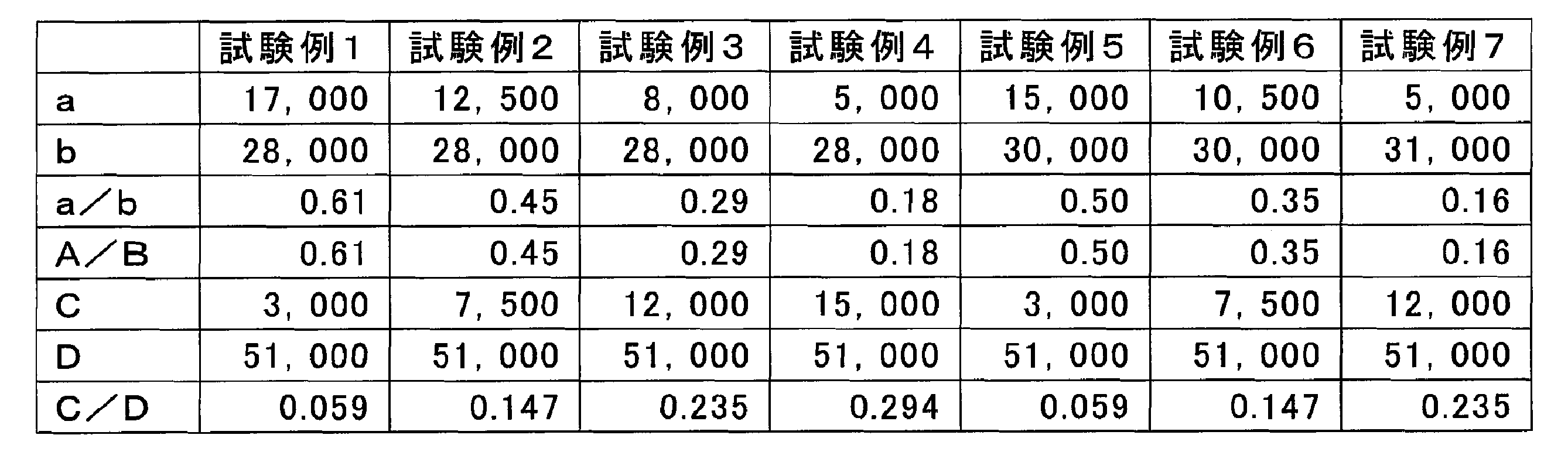
シミュレーションにはFloDEF(メンター・グラフィックス・コーポレーション製)を使用した。流体試料として比重1の流体を下記表2に示す流速で送液し、バッファーとして比重1の流体を下記表2に示す流速で送液した場合をそれぞれシミュレーションした。また、分離流路の長さは、無限遠とした。シミュレーションにより、分離流路における合流部から0.1mmの領域における層流の流跡線、及び、合流部から1.8~1.9mmの領域における流跡線を描画した。

図3の(a)~(g)は、それぞれ試験例1~7の分離デバイスのシミュレーション結果を示す図である。また、図4は、シミュレーションにより算出された、分離流路における合流部から1.8mmの位置の流跡線のうち、最も上の位置(流れ方向に垂直な面における位置)の流跡線と、合流部における流跡線のうち、最も上の位置(流れ方向に垂直な面における位置)の流跡線の差、すなわち、流体試料の層流が、分離流路においてどれだけ移動したかを示すグラフである。
その結果、試験例1~7のいずれの流路においても、流体試料の層流が第1のバイパス流路側に移動することが明らかとなった。移動量(ずれ量)は最大で約30μmであった。流体試料の層流が第1のバイパス流路側に移動すると、流体試料は、回収部において第1の回収流路に回収されやすくなる。このため、流体試料が、標的粒子が回収される第2の回収流路に混入しにくくなり、標的粒子の回収を精度よく行うことができる。
[実験例2]
実験例1でシミュレーションした試験例1、4、5、7の分離デバイスを実際に製造した。また、比較のために試験例8の分離デバイスを製造した。製造した各試験例の分離デバイスの各断面積を下記表3に示す。表3中、A、B、a、b、α、β、C、Dは、分離デバイスにおいて、それぞれ表1におけるものと同様の位置の断面積(μm2)を表す。また、表3には、a/b、A/B、C/Dの値も示す。全ての分離デバイスにおいて、分離流路の長さは12mmであった。
実験例1でシミュレーションした試験例1、4、5、7の分離デバイスを実際に製造した。また、比較のために試験例8の分離デバイスを製造した。製造した各試験例の分離デバイスの各断面積を下記表3に示す。表3中、A、B、a、b、α、β、C、Dは、分離デバイスにおいて、それぞれ表1におけるものと同様の位置の断面積(μm2)を表す。また、表3には、a/b、A/B、C/Dの値も示す。全ての分離デバイスにおいて、分離流路の長さは12mmであった。

続いて、これらの分離デバイスに流体試料及びバッファーを導入し、流体試料の層流の流れを観察した。流体試料として、ヒトから採取した血液を、1%BSA、5mM EDTA含有PBSバッファーで2倍希釈したサンプルを送液した。また、バッファーとして、1%BSA、5mM EDTA含有PBSバッファーを送液した。試験例1、4、5、7の分離デバイスにおいては、流体試料及びバッファーをそれぞれ上記表2と同じ流速で送液した。試験例8の分離デバイスにおいては、流体試料を流速100μL/分で送液し、バッファーを流速1,000μL/分で送液した。
図5の(a)~(e)は、それぞれ試験例1、4、5、7、及び8の各分離デバイスの分離流路の先頭部分、中間部分、及び尾部部分を撮影した写真である。
その結果、図5の(a)~(d)に示すように、試験例1、4、5、及び7の分離デバイスでは、いずれも流体試料の層流が流体試料の層流が第1のバイパス流路側に移動することが明らかとなった。上述したように、流体試料の層流が第1のバイパス流路側に移動すると、流体試料は、回収部において第1の回収流路に回収されやすくなる。このため、流体試料が、標的粒子が回収される第2の回収流路に混入しにくくなり、標的粒子の回収を精度よく行うことができる。
一方、図5の(e)に示すように、試験例8の分離デバイスでは、流体試料の層流が第2のバイパス流路側に移動する様子が観察された。この状態では、流体試料が第2の回収流路に混入し、標的粒子の分離能が低下してしまう場合がある。
以上の結果から、上記断面積A、B、a、bが下記式(1)を満たす分離デバイスでは、流体試料中の標的粒子を精度よく分離することができることが明らかとなった。
(A/B)≦(a/b)…(1)
(A/B)≦(a/b)…(1)
本発明によれば、流体試料中の標的粒子を精度よく分離する技術を提供することができる。
20…DLDマイクロ流路の基本構造(分離エリア)、21…障害物構造(ピラー)、22…閾値以上の大きさを有する粒子、23…閾値未満の大きさを有する粒子、100…分離デバイス、110…分離流路、111…ピラー、120…流体導入部、121…第1の導入口、122…第1の流路、1221…第1のバイパス流路、1222…第2のバイパス流路、1223…隔壁、123…第1の分岐部、124…第2の導入口、125…第2の流路、126…合流部、130…回収部、131…第1の回収流路、132…第2の回収流路、134,135…排出口、A,B,a,b,α,β,C,D…断面積。
Claims (6)
- 閾値以上の大きさを有する標的粒子及び閾値未満の大きさを有する非標的粒子を含む流体試料から、前記標的粒子を分離する分離デバイスであって、
流体中の粒子を大きさにより分離する分離流路と、
前記分離流路の上流側に接続され、前記分離流路に前記流体試料及びバッファーを導入する流体導入部と、
前記分離流路の下流側に接続され、前記標的粒子を含む流体及び前記非標的粒子を含む流体をそれぞれ回収する回収部と、を有し、
前記流体導入部は、
前記バッファーを導入する第1の導入口と、前記第1の導入口に接続され、前記バッファーが流れる第1の流路と、
前記第1の流路を第1のバイパス流路及び第2のバイパス流路に分岐する第1の分岐部と、
前記第1の分岐部の下流側に位置し、前記流体試料を導入する第2の導入口と、前記第2の導入口に接続され、前記流体試料が流れる第2の流路と、
前記第1のバイパス流路、前記第2の流路及び前記第2のバイパス流路が合流する合流部と、を有し、
前記第1の分岐部における前記第1のバイパス流路の流れ方向に垂直な面における断面積Aと、
前記第1の分岐部における前記第2のバイパス流路の流れ方向に垂直な面における断面積Bと、
前記合流部における前記第1のバイパス流路の流れ方向に垂直な面における断面積aと、
前記合流部における前記第2のバイパス流路の流れ方向に垂直な面における断面積bとが、下記式(1)を満たし、
前記回収部は、
前記非標的粒子を含む流体が流れる第1の回収流路と、
前記標的粒子を含む流体が流れる第2の回収流路と、を有し、
前記第1の回収流路は前記分離流路の前記第1のバイパス流路側に接続しており、前記第2の回収流路は、前記分離流路の前記第2のバイパス流路側に接続している、
分離デバイス。
(A/B)≦(a/b)…(1) - 前記断面積a及び前記断面積bが、下記式(2)を満たす、請求項1に記載の分離デバイス。
a≦b…(2) - 前記回収部は、前記分離流路を第1の回収流路及び第2の回収流路に分岐する第2の分岐部を有し、
前記第2の分岐部における前記第1の回収流路の流れ方向に垂直な面における断面積αと、
前記第2の分岐部における前記第2の回収流路の流れ方向に垂直な面における断面積βが、下記式(3)を満たす、請求項1又は2に記載の分離デバイス。
(a/b)<(α/β)…(3) - 前記合流部における前記第2の流路の流れ方向に垂直な面における断面積が、前記分離流路の流れ方向に垂直な面における断面積の5~30%である、請求項1~3のいずれか一項に記載の分離デバイス。
- 前記分離流路は、決定論的横置換法により前記標的粒子を分離する、請求項1~4のいずれか一項に記載の分離デバイス。
- 前記閾値以上の大きさを有する標的粒子及び前記閾値未満の大きさを有する非標的粒子を含む前記流体試料から、前記標的粒子を分離する方法であって、
請求項1~5のいずれか一項に記載の分離デバイスの前記第1の導入口から前記バッファーを導入し、前記第2の導入口から前記流体試料を導入することと、
前記回収部から前記標的粒子を含む流体又は前記非標的粒子を含む流体を回収することと、を含む、方法。
Applications Claiming Priority (2)
| Application Number | Priority Date | Filing Date | Title |
|---|---|---|---|
| JP2019-115558 | 2019-06-21 | ||
| JP2019115558 | 2019-06-21 |
Publications (1)
| Publication Number | Publication Date |
|---|---|
| WO2020255753A1 true WO2020255753A1 (ja) | 2020-12-24 |
Family
ID=74037466
Family Applications (1)
| Application Number | Title | Priority Date | Filing Date |
|---|---|---|---|
| PCT/JP2020/022295 Ceased WO2020255753A1 (ja) | 2019-06-21 | 2020-06-05 | 分離デバイス及び分離方法 |
Country Status (1)
| Country | Link |
|---|---|
| WO (1) | WO2020255753A1 (ja) |
Citations (1)
| Publication number | Priority date | Publication date | Assignee | Title |
|---|---|---|---|---|
| WO2016136273A1 (ja) * | 2015-02-27 | 2016-09-01 | 凸版印刷株式会社 | 細胞を分離する方法、およびそのためのデバイス |
-
2020
- 2020-06-05 WO PCT/JP2020/022295 patent/WO2020255753A1/ja not_active Ceased
Patent Citations (1)
| Publication number | Priority date | Publication date | Assignee | Title |
|---|---|---|---|---|
| WO2016136273A1 (ja) * | 2015-02-27 | 2016-09-01 | 凸版印刷株式会社 | 細胞を分離する方法、およびそのためのデバイス |
Similar Documents
| Publication | Publication Date | Title |
|---|---|---|
| US7735652B2 (en) | Apparatus and method for continuous particle separation | |
| Wang et al. | Vortex-aided inertial microfluidic device for continuous particle separation with high size-selectivity, efficiency, and purity | |
| Nam et al. | Hybrid capillary-inserted microfluidic device for sheathless particle focusing and separation in viscoelastic flow | |
| CN107250343B (zh) | 分离细胞的方法及用于该方法的器件 | |
| Lenshof et al. | Continuous separation of cells and particles in microfluidic systems | |
| Gossett et al. | Label-free cell separation and sorting in microfluidic systems | |
| US9090663B2 (en) | Systems and methods for the capture and separation of microparticles | |
| JP6744302B2 (ja) | ミクロ流体装置における粒子の分類 | |
| JP6031109B2 (ja) | 形状に基づく粒子仕分装置及び方法 | |
| KR101807256B1 (ko) | 입자 분리 장치 및 입자 분리 방법 | |
| JP6933212B2 (ja) | 液体媒体の置換方法及び該方法のための流路デバイス | |
| US20140326339A1 (en) | Systems and methods for particle focusing in microchannels | |
| Tottori et al. | Separation of viable and nonviable mammalian cells using a deterministic lateral displacement microfluidic device | |
| Sim et al. | Multistage-multiorifice flow fractionation (MS-MOFF): continuous size-based separation of microspheres using multiple series of contraction/expansion microchannels | |
| Marioli et al. | Continuous asymmetrical flow field-flow fractionation for the purification of proteins and nanoparticles | |
| JP2005205387A (ja) | 連続粒子分級方法 | |
| WO2021050006A1 (en) | Inertial microfluidic device and method of separating particles in a fluid sample based on particle size using inertial microfluidic device | |
| Luo et al. | Microfluidic dielectrophoretic sorter using gel vertical electrodes | |
| KR101929924B1 (ko) | 수력학을 이용한 마이크로 입자 분리용 미세유로 바이오칩 | |
| JP6403190B2 (ja) | マイクロ流路構造体及び粒子の分離方法 | |
| KR102747514B1 (ko) | 미세유체 입자 분리 향상 방법 및 이의 장치 | |
| JP2007021465A (ja) | 粒子を連続的に濃縮・分離するための流路構造および方法 | |
| Zhao et al. | Microfluidic separation of viruses from blood cells based on intrinsic transport processes | |
| JP2013152171A (ja) | 血液中の粒子分離装置 | |
| Kumar et al. | Micropatterning in BioMEMS for Separation of Cells |
Legal Events
| Date | Code | Title | Description |
|---|---|---|---|
| 121 | Ep: the epo has been informed by wipo that ep was designated in this application |
Ref document number: 20827484 Country of ref document: EP Kind code of ref document: A1 |
|
| NENP | Non-entry into the national phase |
Ref country code: DE |
|
| 122 | Ep: pct application non-entry in european phase |
Ref document number: 20827484 Country of ref document: EP Kind code of ref document: A1 |
|
| NENP | Non-entry into the national phase |
Ref country code: JP |