WO2020255592A1 - モータ - Google Patents
モータ Download PDFInfo
- Publication number
- WO2020255592A1 WO2020255592A1 PCT/JP2020/019148 JP2020019148W WO2020255592A1 WO 2020255592 A1 WO2020255592 A1 WO 2020255592A1 JP 2020019148 W JP2020019148 W JP 2020019148W WO 2020255592 A1 WO2020255592 A1 WO 2020255592A1
- Authority
- WO
- WIPO (PCT)
- Prior art keywords
- material cover
- motor
- mold resin
- axial direction
- coil
- Prior art date
- Legal status (The legal status is an assumption and is not a legal conclusion. Google has not performed a legal analysis and makes no representation as to the accuracy of the status listed.)
- Ceased
Links
Images


Classifications
-
- H—ELECTRICITY
- H02—GENERATION; CONVERSION OR DISTRIBUTION OF ELECTRIC POWER
- H02K—DYNAMO-ELECTRIC MACHINES
- H02K5/00—Casings; Enclosures; Supports
- H02K5/02—Casings or enclosures characterised by the material thereof
-
- H—ELECTRICITY
- H02—GENERATION; CONVERSION OR DISTRIBUTION OF ELECTRIC POWER
- H02K—DYNAMO-ELECTRIC MACHINES
- H02K5/00—Casings; Enclosures; Supports
- H02K5/04—Casings or enclosures characterised by the shape, form or construction thereof
- H02K5/08—Insulating casings
-
- H—ELECTRICITY
- H02—GENERATION; CONVERSION OR DISTRIBUTION OF ELECTRIC POWER
- H02K—DYNAMO-ELECTRIC MACHINES
- H02K2213/00—Specific aspects, not otherwise provided for and not covered by codes H02K2201/00 - H02K2211/00
- H02K2213/06—Machines characterised by the presence of fail safe, back up, redundant or other similar emergency arrangements
-
- H—ELECTRICITY
- H02—GENERATION; CONVERSION OR DISTRIBUTION OF ELECTRIC POWER
- H02K—DYNAMO-ELECTRIC MACHINES
- H02K5/00—Casings; Enclosures; Supports
- H02K5/04—Casings or enclosures characterised by the shape, form or construction thereof
- H02K5/12—Casings or enclosures characterised by the shape, form or construction thereof specially adapted for operating in liquid or gas
- H02K5/136—Casings or enclosures characterised by the shape, form or construction thereof specially adapted for operating in liquid or gas explosion-proof
Definitions
- the present disclosure relates to the field of motors, particularly to motors in which the stator is covered with a mold resin.
- FIG. 7 is a cross-sectional view showing a configuration example of the conventional motor 500.
- the motor 500 including the stator 510 and the rotor 540 the motor 500 in which the stator 510 is covered with the mold resin 530 is also referred to as a mold motor and is already widely known.
- the stator 510 has a stator core 511 made of a plurality of metal plates and a coil 512 in which a winding is wound around the stator core 511.
- the coil 512 provided on the stator 510 is covered with the mold resin 530.
- the portion of the coil 512 that protrudes from the stator core 511 is also referred to as a coil end 512a.
- An insulator 513 is attached between the coil 512 and the stator core 511 for the purpose of electrical insulation between the coil 512 and the stator core 511.
- the coil 512 By the way, if an excessive current flows through the coil 512, the coil 512 generates heat and becomes extremely hot, which may cause a rare short circuit. That is, the outer circumference of the conductor of the winding forming the coil 512 is covered with an insulator. However, when the coil 512 generates heat, the conductors may be short-circuited due to the insulator being melted by heat in the winding whose outer circumference is insulated by the insulator. If a rare short circuit occurs in the coil 512 in a special environment in which no safety protection device is activated, sparks may occur. The spark may ignite the gas generated by heating the insulator 513 or the like.
- the physical characteristics of the mold resin 530 may deteriorate due to the applied heat or the like.
- the mold resin 530 cracks or the like.
- the gas generated from the insulator 513 or the like may ignite, and the ignited fire may be emitted from the cracked portion generated in the mold resin 530. There is a risk of leakage to the outside of the motor 500.
- the portion of the coil 512 other than the coil end 512a is surrounded by the stator core 511, the possibility of fire or smoke leaking to the outside is extremely low.
- the coil end 512a protrudes from the stator core 511, it is in contact with the mold resin 530. Therefore, there is a possibility that fire or smoke may leak to the outside due to ignition from the portion of the mold resin 530 that comes into contact with the coil end 512a.
- a safety protection circuit for preventing an excessive current from flowing through the coil 512 of the stator 510 is provided inside the motor 500 (for example, inside the circuit board 534 provided inside the motor 500) or inside the motor device.
- the motor 500 covered the coil ends 512a protruding from the end of the stator core 511 to both ends in the axial direction with metal covers 517 and 518.
- One metal cover 517 was located inside the mold resin 530, and the other metal cover 518 was attached so as to cover the mold resin 530 via the outer shell.
- the metal cover 517 located inside the mold resin 530. Further, if the position of the metal cover 517 is changed so as to cover the outer shell of the mold resin 530 like the metal cover 518, the metal cover 517 interferes with the mounting legs 531 existing in the outer shell of the mold resin 530.
- the motor 500 is highly safe because it prevents fire and smoke from leaking from the inside of the motor to the outside.
- the motor 500 is required to be arranged at the same position as the conventional motor. That is, it is not desirable that the position of the mounting leg of the motor 500 is changed from the position of the mounting leg of the conventional motor.
- the problem to be solved by the present disclosure is to provide a motor capable of preventing fire and smoke from being emitted from the motor to the outside without changing the position of the mounting legs.
- the stator has a stator core, a stator having a coil wound around the stator core, and a rotating shaft extending in the axial direction, and the stator is rotatable.
- a motor including a rotor located inside the motor and a mold resin covering the stator, wherein the coil has coil ends protruding from the stator core on both sides in the axial direction of the mold resin.
- a first noncombustible material cover is attached so as to surround one of the coil ends protruding on both sides in the axial direction over the circumferential direction, and the outer peripheral surface of the mold resin is attached.
- a plurality of mounting legs are provided along the circumferential direction, and the root portions of each of the plurality of mounting legs connected to the outer peripheral surface of the mold resin are extended along the circumferential direction.
- Circumferential grooves are formed on both sides in the circumferential direction and on one side in the axial direction, and the tips on one side in the axial direction of the first noncombustible material cover are each of the plurality of mounting legs.
- the stator core By providing the first noncombustible material cover on the outer peripheral surface of the mold resin, the stator core can be formed larger and the motor capacity can be improved without changing the outer diameter of the motor. Further, by forming a circumferential groove in the mounting leg and inserting the tip of the first noncombustible material cover into the circumferential groove, the mounting leg and the mounting surface can be connected to the mounting leg without changing the position in the axial direction. Since interference with the first non-combustible material cover can be avoided, the motor can be arranged at the same position as the conventional motor, and fire and smoke can be prevented from being emitted from the motor to the outside.
- one or more positioning portions that come into contact with the tip of the first noncombustible material cover are formed on the outer peripheral surface of the mold resin, and the one or more positioning portions are formed.
- the portions are formed so as to be located between the plurality of mounting legs in the circumferential direction, and the first noncombustible material cover is mounted on the one or more positioning portions in the axial direction.
- the end portion on the side is formed at a position where the first non-combustible material cover is mounted on the side of the bottom portion of the circumferential groove so as to come into contact with the tip end of the first non-combustible material cover.
- the tip of the first non-combustible material cover By configuring the tip of the first non-combustible material cover to come into contact with the positioning portion before reaching the bottom of the circumferential groove, the tip of the first non-combustible material cover is attached when the first non-combustible material cover is attached. However, it is possible to prevent the mounting legs from being cracked or buckled by applying stress to the mounting legs.
- one or more positioning portions are formed on the outer peripheral surface of the mold resin, and the one or more positioning portions are formed on the plurality of mounting legs in the circumferential direction.
- a cut having a shape corresponding to the positioning portion is formed at the tip of the first noncombustible material cover, at a position corresponding to the one or more positioning portions in the circumferential direction.
- a notch is formed, and the one or more positioning portions are the bottom portion of the circumferential groove and the first one at a position where they engage with the notch portion of the first noncombustible material cover in the axial direction. It is formed at a position where it does not come into contact with the tip of the non-combustible material cover.
- the first non-combustible material cover By forming a positioning portion on the outer peripheral surface of the mold resin and forming a notch corresponding to the positioning portion at the tip of the first non-combustible material cover, the first non-combustible material cover can be simply positioned in the axial direction. Since it can be positioned in the circumferential direction, the first noncombustible material cover is prevented from swinging in the circumferential direction due to vibration of the motor or the like.
- a plurality of the positioning portions are formed on the outer peripheral surface of the mold resin at equal intervals in the circumferential direction.
- the first non-combustible material cover is made of metal.
- the workability and wearability of the first non-combustible material cover can be effectively ensured.
- the first non-combustible material cover is made of iron, stainless steel, brass, or aluminum.
- the first non-combustible material cover By forming the first non-combustible material cover from iron, stainless steel, brass, or aluminum, it is possible to effectively secure the workability and wearability of the first non-combustible material cover while suppressing the cost.
- the cross-sectional shape of the circumferential groove is substantially U-shaped.
- the cross-sectional shape of the circumferential groove is tapered.
- a thick portion having a cross-sectional shape corresponding to the cross-sectional shape of the circumferential groove is formed at the tip of the first non-combustible material cover.
- the tip of the first non-combustible material cover buckles or dust becomes the first non-combustible material. It is possible to prevent the material cover from entering the gap between the tip of the material cover and the circumferential groove.
- the tip of the first noncombustible material cover was chamfered.
- the length of the mounting leg in the axial direction is in the range of 9 mm to 14 mm.
- the strength of the mounting leg can be effectively secured.
- the depth of the circumferential groove in the axial direction is in the range of 2 mm to 4 mm.
- the mounting legs are formed with reinforcing ribs on the side opposite to the side in which the circumferential groove is formed in the axial direction.
- the strength of the mounting legs can be secured more effectively.
- a second coil end is surrounded by the circumferential direction of the other coil end of the coil ends protruding on both sides in the axial direction on the outer peripheral surface of the mold resin.
- a non-combustible material cover is attached.
- the first noncombustible material cover also covers the crossover of the coil.
- the stator has a stator core, a stator having a coil wound around the stator core, and a rotating shaft extending in the axial direction, and the stator is rotatable.
- a motor including a rotor located inside the motor and a mold resin covering the stator, wherein the coil has coil ends protruding from the stator core on both sides in the axial direction of the mold resin.
- a first noncombustible material cover is attached so as to surround one of the coil ends protruding on both sides in the axial direction over the circumferential direction, and the outer peripheral surface of the mold resin is attached.
- a plurality of mounting legs are provided along the circumferential direction, and at the tip of the first noncombustible material cover, a plurality of cuttings are made at positions corresponding to the plurality of mounting legs in the circumferential direction.
- a motor is provided in which a notch is formed, and the first noncombustible material cover is mounted so that each of the plurality of mounting legs is inserted into the plurality of notches. ..
- the stator core By providing the first noncombustible material cover on the outer peripheral surface of the mold resin, the stator core can be formed larger and the motor capacity can be improved without changing the outer diameter of the motor. Further, by forming a notch at the tip of the first noncombustible material cover and allowing the mounting leg to enter the notch, the mounting leg and the mounting leg can be connected to the mounting leg without changing the position of the mounting surface in the axial direction. Since interference with the first noncombustible material cover can be avoided, the motor can be arranged at the same position as the conventional motor, and fire and smoke can be prevented from being emitted from the motor to the outside.
- the motor of the present disclosure it is possible to provide a motor that can prevent fire and smoke from being emitted from the motor to the outside without changing the position of the mounting legs.
- FIG. 1 is a perspective view showing the appearance of the motor 100 according to the present disclosure.
- FIG. 2 is a cross-sectional view of the motor 100 along the axial direction X.
- FIG. 3 is another cross-sectional view of the motor 100 along the axial direction X.
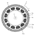
- FIG. 4 is a cross-sectional view of the motor 100 along the line AA in FIG.
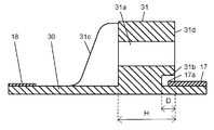
- FIG. 5 is an enlarged view of a part of FIG. 2.
- FIG. 6 is an enlarged view of a part of FIG.
- FIG. 7 is a cross-sectional view showing a configuration example of a conventional motor.
- FIG. 1 is a perspective view showing the appearance of the motor 100 according to the present disclosure.
- FIG. 2 is a cross-sectional view of the motor 100 along the axial direction X, and is a view in which the motor 100 is cut along the axial direction X at a position where the mounting legs 31 are present.
- FIG. 3 is another cross-sectional view of the motor 100 along the axial direction X, and is a view in which the motor 100 is cut along the axial direction X at a position where the positioning portion 32 exists.
- FIG. 4 is a cross-sectional view of the motor 100 along the line AA in FIG.
- FIG. 5 is an enlarged view of a part of FIG. 2.
- FIG. 6 is an enlarged view of a part of FIG.
- the motor 100 as an example of a brushless motor provided with a permanent magnet in the rotor will be described.
- the direction in which the rotating shaft 41 extends is defined as the axial direction X.
- the direction extending from the center of the rotating shaft 41 is referred to as the radial direction Y, and the direction rotating around the center of the rotating shaft 41 is referred to as the circumferential direction Z.
- the motor 100 in the present embodiment includes a stator 10, a rotor 40, a first bracket 15, a circuit board 19, and two bearings 20A and 20B.
- the non-combustible material cover 17 of 1 and the second non-combustible material cover 18 are provided.
- the stator 10 includes a coil assembly 14 including a stator core 11, a coil 12, and an insulator 13.
- the coil assembly 14 is assembled by winding the coil 12 around the stator core 11 via an insulator 13 made of an insulating material.
- the stator core 11 has a ring-shaped yoke 11a and a plurality of tooth 11b extending radially inward from the inner peripheral surface of the yoke 11a.
- the plurality of tooth 11bs are arranged at equal intervals in the circumferential direction Z while forming slots 11c which are openings between the tooth 11bs.
- a tooth tip portion 11bb extending in the circumferential direction Z is formed so as to be wider than the tooth intermediate portion 11ba.
- the inner peripheral surface of the tooth tip portion 11bb serves as a magnetic pole surface facing the outer peripheral surface of the rotor 40.
- a coil 12 is formed by winding the winding around each tooth 11b while passing the winding through the opening space of the slot 11c with respect to the stator core 11 having such a configuration.
- the coil 12 has coil ends 12a protruding from the stator core 11 on both sides in the axial direction X.
- the portion of the coil 12 other than the coil end 12a is housed in the slot 11c of the stator core 11.
- the coils 12 are connected by a crossover (not shown).
- the crossover is usually arranged on the outer peripheral surface of the insulator 13 in the radial direction.
- the coil 12 wound around each tooth 11b is energized and driven by, for example, three-phase alternating current having U-phase, V-phase, and W-phase, which are electrically different from each other by 120 degrees.
- the motor 100 includes a second bracket 16 arranged so as to project in the direction opposite to the direction in which the first bracket 15 is located. ..
- the stator 10 is integrally molded with a mold resin 30 so that the coil assembly 14 and the second bracket 16 are arranged at predetermined positions and these members are covered with the resin material.
- the stator 10 configured in this way has a substantially cylindrical shape, and further, a mounting leg 31 for mounting the motor 100 to an external device or the like and a first noncombustible material cover 17 are provided on the outer peripheral surface of the cylinder.
- a plurality of positioning portions 32 for positioning are provided along the circumferential direction (see below for details). Further, one end surface (the right end surface in FIGS.
- both end faces in the axial direction X of the stator 10 is open, and the first bracket 15 is attached so as to cover the opening.
- the other end face (the left end face in FIGS. 2 and 3) is closed, and the second bracket 16 is arranged so as to protrude as described above.
- the motor 100 is an inner rotor type motor in which the rotor 40 is arranged inside the stator 10, and in the present embodiment, an example of such an inner rotor type motor 100 will be described.
- the rotor 40 includes a rotating body 42 that holds a plurality of magnets 44 around a rotating shaft 41 that is rotatably held by the bearing 20A and the bearing 20B. Further, the rotating body 42 includes a rotor core 43 and a plurality of magnets 44.
- the rotor core 43 is configured by stacking, for example, a plurality of thin iron plates in the axial direction X, and is fixed to the rotating shaft 41 at the central portion.
- the plurality of magnets 44 are permanent magnets, and in the present embodiment, the plurality of magnets 44 are assembled on the outer peripheral surface of the rotor core 43 so that the polarities of the adjacent magnets 44 are alternately changed.
- the rotating shaft 41 to which such a rotating body 42 is fastened is rotatably supported by two bearings, a bearing 20A and a bearing 20B.
- the bearings 20A and 20B are ball bearings.
- such bearings 20A and 20B are fixed via metal first brackets 15 and second brackets 16 arranged on both sides of the stator 10 in the axial direction, respectively.
- the first bracket 15 has a substantially disk shape and is configured to be mounted on the opening side of the stator 10. Further, a holding portion 15a recessed in a cylindrical shape is formed in the central portion of the first bracket 15, and the bearing 20A is held by the holding portion 15a. That is, by attaching the first bracket 15 in which the bearing 20A is inserted into the holding portion 15a to the stator 10, one side of the rotating shaft 41 is rotatably supported.
- the second bracket 16 has a smaller diameter than the first bracket 15 and has a shape in which a disk and a cylinder are combined. Further, by the mold molding described above, the second bracket 16 is fixed to the mold resin 30 together with the stator 10. Further, a holding portion 16a recessed in a cylindrical shape is also formed in the central portion of the second bracket 16, and the bearing 20B is held by the holding portion 16a. That is, by inserting the bearing 20B into the holding portion 16a, the other side of the rotating shaft 41 is rotatably supported. Further, in the present embodiment, an opening 16b is formed in the center of the holding portion 16a, and the rotating shaft 41 penetrates the opening 16b and projects outward.
- the protruding portion of the rotating shaft 41 becomes the output shaft 41p for connecting a load or the like.
- the extending side of the output shaft 41p in the axial direction X is referred to as the “output shaft side”, and the opposite side is referred to as the “anti-output shaft side”.
- the "anti-output shaft side” is also referred to as the "side on which the first non-combustible material cover is mounted”.
- the motor 100 incorporates the circuit board 19 on the opening side of the stator 10.
- the circuit board 19 has a substantially disk-like shape, and an opening 19b for passing the rotating shaft 41 is formed in the central portion thereof.
- Electronic components such as a drive circuit and a safety protection circuit are mounted on the circuit board 19, and a connection line for applying a power supply voltage and a control signal are also connected. Then, a connecting wire for connecting to the outside is drawn out to the outside through a wiring hole (not shown) provided in the mold resin 30.
- the coil 12 will receive an excessive current. It will flow. Then, the coil 12 and the crossover wire generate heat and become extremely hot. As a result, a rare short may occur, a spark may be generated due to the rare short, and the generated spark may ignite the gas generated from the insulator 13 or the like and ignite. In particular, since the coil end 12a and the crossover as described above protrude from the stator core 11, there is a high possibility that such a problem will occur.
- a first non-combustible material cover 17 and a second non-combustible material cover 18 are provided.
- a first metal non-combustible material cover 17 is mounted on the counter-output shaft side of the stator 10.
- the first non-combustible material cover 17 is formed on the outer peripheral surface of the mold resin 30 so as to surround the coil end 12a on the counter-output shaft side of the coil ends 12a protruding on both sides in the axial direction X over the circumferential direction Z. It is installed.
- the first noncombustible material cover 17 has a cylindrical shape with both ends open and has a uniform diameter, and the inner diameter of the cylinder is substantially equal to the outer diameter of the stator 10.
- the first non-combustible material cover 17 When the first non-combustible material cover 17 is attached to the outer peripheral surface of the mold resin 30 by, for example, press fitting, the first non-combustible material cover 17 covers the coil end 12a on the anti-output shaft side in the axial direction X in the length range thereof. Include in. That is, the first noncombustible material cover 17 covers the entire coil end 12a on the non-output shaft side in the axial direction X. The first noncombustible material cover 17 also covers a crossover line located on the outer peripheral surface of the insulator 13 in the radial direction.
- the first non-combustible material cover 17 covers the coil end 12a and the crossover on the anti-output shaft side. Therefore, even if a fire breaks out due to a problem such as a rare short circuit as described above and the fire tries to spread radially outward from the insulator 13 or the crossover wire, the fire or smoke is blocked by the first noncombustible material cover 17. , It is possible to prevent fire and smoke from being emitted to the outside of the motor 100.
- each mounting leg 31 is provided with a bolt hole 31a extending in the axial direction X through which a mounting bolt is inserted. Further, on the end surface of each mounting leg 31 on the opposite output shaft side, the root portion of the mounting leg 31 connected to the outer peripheral surface of the mold resin 30 is extended along the circumferential direction Z on both sides of the circumferential direction Z and in the axial direction.
- a circumferential groove 31b having a substantially U-shaped cross section formed on one side of the X is formed.
- the tip 17a on the output shaft side of the first non-combustible material cover 17 enters each of the circumferential grooves 31b of the plurality of mounting legs 31. I'm out.
- reinforcing ribs 31c are appropriately formed on both sides of the bolt holes 31a.
- the position of the axial direction X of the mounting surface 31d of the mounting leg 31 is changed.
- the first noncombustible material cover 17 can be mounted on the outer peripheral surface of the mold resin 30 without changing the distance L in the axial direction X between the mounting surface 31d and the tip of the output shaft 21. it can.
- the depth D of the circumferential groove 31b in the axial direction X can be appropriately set according to the amount of interference between the mounting legs 31 and the first noncombustible material cover 17 (for example, set to 2 mm to 4 mm). ).
- the length H of the mounting legs 31 in the axial direction X (that is, the length of the main body of the mounting legs 31 excluding the reinforcing ribs 31c in the axial direction X) is 7 mm. It should be set to ⁇ 10 mm.
- the circumferential groove 31b of about 2 mm to 4 mm is provided, for example, the length H of the mounting leg 31 in the axial direction X can be set to 9 mm to 14 mm.
- one or more positioning portions 32 that come into contact with the tip 17a of the first noncombustible material cover 17 are integrally formed on the outer peripheral surface of the mold resin 30.
- the positioning portion 32 is formed so as to project outward in the radial direction Y on the outer peripheral surface of the mold resin 30, and has a substantially rectangular shape long in the circumferential direction Z.
- a plurality of (for example, four) positioning portions 32 are provided between the adjacent mounting legs 31 at equal intervals in the circumferential direction Z.
- each positioning portion 32 the end portion of the positioning portion 32 on the anti-output shaft side is in contact with the tip 17a of the first noncombustible material cover 17 on the anti-output shaft side of the bottom portion of the circumferential groove 31b in the axial direction X. It is formed at the position where it touches.
- the tip 17a of the first non-combustible material cover 17 hits the positioning portion 32 before reaching the bottom of the circumferential groove 31b. Since they are in contact with each other, the first noncombustible material cover 17 is positioned in the axial direction X.
- the tip 17a of the first non-combustible material cover 17 By configuring the tip 17a of the first non-combustible material cover 17 to come into contact with the positioning portion 32 before reaching the bottom of the circumferential groove 31b, the first non-combustible material cover is press-fitted when the first non-combustible material cover is press-fitted. It is possible to prevent the tip 17a of the material cover 17 from applying stress to the mounting legs 31 to cause cracks or buckling in the mounting legs 31.
- a second metal non-combustible material cover 18 is attached to the output shaft side of the mold resin 30.
- the second noncombustible material cover 18 is attached to the outer peripheral surface of the mold resin 30 so as to surround the coil end 12a on the output shaft side of the coil ends 12a protruding on both sides in the axial direction X over the circumferential direction Z.
- the second non-combustible material cover 18 has a hollow cup shape having an opening 18a in the center.
- the second noncombustible material cover 18 is attached to the stator 10 via the mold resin 30 so that the second bracket 16 included in the stator 10 penetrates the opening 18a.
- the second noncombustible material cover 18 In a state where the second noncombustible material cover 18 is attached to the outer peripheral surface of the mold resin 30, the second noncombustible material cover 18 includes the coil end 12a on the output shaft side within the length range in the axial direction X. That is, the second noncombustible material cover 18 covers the entire coil end 12a on the output shaft side in the axial direction X. The second noncombustible material cover 18 also covers a crossover line located on the outer peripheral surface of the insulator 13 in the radial direction.
- the second noncombustible material cover 18 covers the coil end 12a and the crossover on the output shaft side. Therefore, even if a fire breaks out due to a problem such as a rare short circuit as described above and the fire tries to spread radially outward from the insulator 13 or the crossover, the second noncombustible material cover 18 blocks the fire and smoke. , It is possible to prevent fire and smoke from being emitted to the outside of the motor 100.
- first non-combustible material cover 17 and the second non-combustible material cover 18 made of metal described above a metal material such as iron, stainless steel, brass or aluminum can be used.
- the rust prevention performance can be improved by plating the surface.
- a hot-dip galvanized steel sheet JIS standard: SGCD
- an electrogalvanized steel sheet JIS standard: SECD
- the above motor 100 is configured by the following procedure.
- the stator 10 is configured by arranging the coil assembly 14 and the second bracket 16 at predetermined positions and integrally molding the mold.
- the bearings 20A and 20B are mounted on both sides of the rotating shaft 41 of the rotor 40.
- the rotor 40 with the bearings 20A and 20B mounted is inserted into the stator 10 so that the output shaft 41p protrudes from the opening 16b of the second bracket 16.
- the bearing 20B is press-fitted into the holding portion 16a of the second bracket 16.
- the first noncombustible material cover 17 is press-fitted into the outer peripheral surface of the mold resin 30 from the anti-output shaft side until it comes into contact with the positioning portion 32.
- the circuit board 19 is mounted in the opening on the counter-output shaft side of the stator 10.
- the connection line connected to the circuit board 19 is drawn out to the outside through a wiring hole provided in the mold resin 30.
- the bearing 20A is press-fitted into the holding portion 15a of the first bracket 15, and the first bracket 15 is mounted on the counter-output shaft side of the stator 10.
- the second noncombustible material cover 18 is mounted on the output shaft side of the stator 10. In this way, the motor 100 as shown in FIGS. 1 to 3 is completed.
- the coil 12 By supplying the power supply voltage, control signal, and the like to the circuit board 19 via the connection line to the motor 100 configured as described above, the coil 12 is energized and driven by the drive circuit mounted on the circuit board 19. To. When the coil 12 is energized, a drive current flows through the coil 12 and a magnetic field is generated from the stator core 11. Then, the alternating magnetic field from the stator core 11 and the magnetic field from the magnet 44 of the rotor 40 generate attractive and repulsive forces according to the polarities of the magnetic fields, and these forces cause the rotor 40 to rotate around the rotating shaft 41. Rotate in direction Z.
- the configuration in which the tip 17a of the first non-combustible material cover 17 is flush with each other in the axial direction X has been described, but one at the tip 17a of the first non-combustible material cover 17 in the circumferential direction Z.
- a notch having a shape corresponding to the positioning portion 32 may be formed at a position corresponding to the positioning portion 32.
- the positioning portion 32 in this modification is With respect to the positioning portion 32 in the above embodiment, it was moved to the anti-output shaft side by the depth of the notch portion. That is, the positioning portion 32 in this modification is the bottom portion of the circumferential groove 31b and the tip end of the first noncombustible material cover 17 at a position where the positioning portion 32 is locked with the notch portion of the first noncombustible material cover 17 in the axial direction X. It is formed at a position where it does not come into contact with 17a.
- the configuration in which one or more positioning portions 32 in contact with the tip 17a of the first noncombustible material cover 17 are formed on the outer peripheral surface of the mold resin 30 has been described. It is also possible to bring the tip 17a of the first noncombustible material cover 17 into contact with the bottom of the circumferential groove 31b of the mounting leg 31 without providing the 32. In this case, preferably, a thick portion having a cross-sectional shape corresponding to the cross-sectional shape of the circumferential groove 31b is formed at the tip 17a of the first non-combustible material cover 17, thereby forming the first non-combustible material cover.
- the cross-sectional shape of the circumferential groove is substantially U-shaped, but the present invention is not limited to this.
- the cross-sectional shape of the circumferential groove 31b may be any shape such as a tapered shape.
- the first noncombustible material cover 17 and the second noncombustible material cover 18 are formed of a noncombustible material such as metal, but the present invention is not limited to this.
- the first non-combustible material cover 17 and the second non-combustible material cover 18 inorganic substances such as ceramics and aluminum hydroxide molded products can also be used.
- the configuration in which the circumferential groove 31b is formed in the mounting leg 31 has been described, but the circumferential direction Z is formed at the tip 17a of the first noncombustible material cover 17 without providing the circumferential groove 31b.
- a plurality of notches may be formed at positions corresponding to each of the plurality of mounting legs 31.
- each of the plurality of mounting legs 31 can also enter the plurality of notches of the first non-combustible material cover 17.
- the non-combustible material cover 17 can be positioned in the axial direction X and the circumferential direction Z.
- a surface magnet type motor (Surface Permanent Magnet Motor: SPM motor) in which the magnet 44 is held on the outer peripheral surface of the rotor 40 has been described as an example, but the magnet 44 is provided inside the rotor core 43. It may be an arranged IPM (Interior Permanent Magnet: internal magnet embedded) type motor.
- the configuration of the present disclosure can be widely applied to a so-called mold motor in which the stator is covered with a mold resin.
Landscapes
- Engineering & Computer Science (AREA)
- Power Engineering (AREA)
- Motor Or Generator Frames (AREA)
- Iron Core Of Rotating Electric Machines (AREA)
Priority Applications (2)
| Application Number | Priority Date | Filing Date | Title |
|---|---|---|---|
| EP20826696.5A EP3989398B1 (en) | 2019-06-20 | 2020-05-13 | Motor |
| JP2021527456A JP7542171B2 (ja) | 2019-06-20 | 2020-05-13 | モータ |
Applications Claiming Priority (2)
| Application Number | Priority Date | Filing Date | Title |
|---|---|---|---|
| CN201920935779.4 | 2019-06-20 | ||
| CN201920935779.4U CN209860692U (zh) | 2019-06-20 | 2019-06-20 | 电动机 |
Publications (1)
| Publication Number | Publication Date |
|---|---|
| WO2020255592A1 true WO2020255592A1 (ja) | 2020-12-24 |
Family
ID=68942389
Family Applications (1)
| Application Number | Title | Priority Date | Filing Date |
|---|---|---|---|
| PCT/JP2020/019148 Ceased WO2020255592A1 (ja) | 2019-06-20 | 2020-05-13 | モータ |
Country Status (4)
| Country | Link |
|---|---|
| EP (1) | EP3989398B1 (https=) |
| JP (1) | JP7542171B2 (https=) |
| CN (1) | CN209860692U (https=) |
| WO (1) | WO2020255592A1 (https=) |
Cited By (1)
| Publication number | Priority date | Publication date | Assignee | Title |
|---|---|---|---|---|
| US12362630B2 (en) * | 2022-03-18 | 2025-07-15 | Makita Corporation | Electric work machine |
Citations (4)
| Publication number | Priority date | Publication date | Assignee | Title |
|---|---|---|---|---|
| JPS57113636U (https=) * | 1980-12-29 | 1982-07-14 | ||
| JP2002106660A (ja) * | 2000-09-28 | 2002-04-10 | Sumitomo Heavy Ind Ltd | モータ付き動力伝達装置 |
| WO2018159537A1 (ja) * | 2017-02-28 | 2018-09-07 | パナソニックIpマネジメント株式会社 | モールドモータ |
| JP2019022416A (ja) * | 2017-07-21 | 2019-02-07 | 日本電産テクノモータ株式会社 | ステータユニット及びモータ |
Family Cites Families (1)
| Publication number | Priority date | Publication date | Assignee | Title |
|---|---|---|---|---|
| EP3547506B1 (en) * | 2016-11-28 | 2026-03-25 | Panasonic Intellectual Property Management Co., Ltd. | Motor |
-
2019
- 2019-06-20 CN CN201920935779.4U patent/CN209860692U/zh active Active
-
2020
- 2020-05-13 JP JP2021527456A patent/JP7542171B2/ja active Active
- 2020-05-13 WO PCT/JP2020/019148 patent/WO2020255592A1/ja not_active Ceased
- 2020-05-13 EP EP20826696.5A patent/EP3989398B1/en active Active
Patent Citations (4)
| Publication number | Priority date | Publication date | Assignee | Title |
|---|---|---|---|---|
| JPS57113636U (https=) * | 1980-12-29 | 1982-07-14 | ||
| JP2002106660A (ja) * | 2000-09-28 | 2002-04-10 | Sumitomo Heavy Ind Ltd | モータ付き動力伝達装置 |
| WO2018159537A1 (ja) * | 2017-02-28 | 2018-09-07 | パナソニックIpマネジメント株式会社 | モールドモータ |
| JP2019022416A (ja) * | 2017-07-21 | 2019-02-07 | 日本電産テクノモータ株式会社 | ステータユニット及びモータ |
Non-Patent Citations (1)
| Title |
|---|
| See also references of EP3989398A4 * |
Cited By (1)
| Publication number | Priority date | Publication date | Assignee | Title |
|---|---|---|---|---|
| US12362630B2 (en) * | 2022-03-18 | 2025-07-15 | Makita Corporation | Electric work machine |
Also Published As
| Publication number | Publication date |
|---|---|
| JPWO2020255592A1 (https=) | 2020-12-24 |
| CN209860692U (zh) | 2019-12-27 |
| JP7542171B2 (ja) | 2024-08-30 |
| EP3989398B1 (en) | 2026-04-01 |
| EP3989398A4 (en) | 2022-08-24 |
| EP3989398A1 (en) | 2022-04-27 |
Similar Documents
| Publication | Publication Date | Title |
|---|---|---|
| JP7489589B2 (ja) | モータ | |
| JP7308391B2 (ja) | モールドモータ | |
| US9325209B2 (en) | Rotating electrical machine and manufacturing method of rotor | |
| KR20190111113A (ko) | 모터 | |
| WO2020255592A1 (ja) | モータ | |
| JPWO2020255592A5 (https=) | ||
| WO2019220956A1 (ja) | モールドモータ | |
| JP7474932B2 (ja) | モールドモータ | |
| JP7445898B2 (ja) | モールドモータ |
Legal Events
| Date | Code | Title | Description |
|---|---|---|---|
| 121 | Ep: the epo has been informed by wipo that ep was designated in this application |
Ref document number: 20826696 Country of ref document: EP Kind code of ref document: A1 |
|
| ENP | Entry into the national phase |
Ref document number: 2021527456 Country of ref document: JP Kind code of ref document: A |
|
| NENP | Non-entry into the national phase |
Ref country code: DE |
|
| WWE | Wipo information: entry into national phase |
Ref document number: 2020826696 Country of ref document: EP |
|
| ENP | Entry into the national phase |
Ref document number: 2020826696 Country of ref document: EP Effective date: 20220120 |
|
| WWG | Wipo information: grant in national office |
Ref document number: 2020826696 Country of ref document: EP |