WO2020255394A1 - 物体管理システム - Google Patents
物体管理システム Download PDFInfo
- Publication number
- WO2020255394A1 WO2020255394A1 PCT/JP2019/024786 JP2019024786W WO2020255394A1 WO 2020255394 A1 WO2020255394 A1 WO 2020255394A1 JP 2019024786 W JP2019024786 W JP 2019024786W WO 2020255394 A1 WO2020255394 A1 WO 2020255394A1
- Authority
- WO
- WIPO (PCT)
- Prior art keywords
- image
- ellipse
- registered
- circle
- collation
- Prior art date
- Legal status (The legal status is an assumption and is not a legal conclusion. Google has not performed a legal analysis and makes no representation as to the accuracy of the status listed.)
- Ceased
Links
Images













Classifications
-
- G—PHYSICS
- G06—COMPUTING OR CALCULATING; COUNTING
- G06V—IMAGE OR VIDEO RECOGNITION OR UNDERSTANDING
- G06V30/00—Character recognition; Recognising digital ink; Document-oriented image-based pattern recognition
- G06V30/10—Character recognition
- G06V30/14—Image acquisition
- G06V30/146—Aligning or centring of the image pick-up or image-field
- G06V30/1473—Recognising objects as potential recognition candidates based on visual cues, e.g. shapes
-
- G—PHYSICS
- G06—COMPUTING OR CALCULATING; COUNTING
- G06V—IMAGE OR VIDEO RECOGNITION OR UNDERSTANDING
- G06V30/00—Character recognition; Recognising digital ink; Document-oriented image-based pattern recognition
- G06V30/10—Character recognition
- G06V30/18—Extraction of features or characteristics of the image
- G06V30/1801—Detecting partial patterns, e.g. edges or contours, or configurations, e.g. loops, corners, strokes or intersections
-
- G—PHYSICS
- G06—COMPUTING OR CALCULATING; COUNTING
- G06T—IMAGE DATA PROCESSING OR GENERATION, IN GENERAL
- G06T7/00—Image analysis
-
- G—PHYSICS
- G06—COMPUTING OR CALCULATING; COUNTING
- G06T—IMAGE DATA PROCESSING OR GENERATION, IN GENERAL
- G06T7/00—Image analysis
- G06T7/60—Analysis of geometric attributes
-
- G—PHYSICS
- G06—COMPUTING OR CALCULATING; COUNTING
- G06V—IMAGE OR VIDEO RECOGNITION OR UNDERSTANDING
- G06V30/00—Character recognition; Recognising digital ink; Document-oriented image-based pattern recognition
- G06V30/10—Character recognition
- G06V30/14—Image acquisition
- G06V30/1444—Selective acquisition, locating or processing of specific regions, e.g. highlighted text, fiducial marks or predetermined fields
- G06V30/1456—Selective acquisition, locating or processing of specific regions, e.g. highlighted text, fiducial marks or predetermined fields based on user interactions
-
- G—PHYSICS
- G06—COMPUTING OR CALCULATING; COUNTING
- G06V—IMAGE OR VIDEO RECOGNITION OR UNDERSTANDING
- G06V30/00—Character recognition; Recognising digital ink; Document-oriented image-based pattern recognition
- G06V30/10—Character recognition
- G06V30/19—Recognition using electronic means
- G06V30/19007—Matching; Proximity measures
- G06V30/19093—Proximity measures, i.e. similarity or distance measures
Definitions
- the present invention relates to an object management system, an object management method, a program, and an object collation system.
- a scanner unit that simultaneously scans a stamp image, a handwriting image, identity verification data, and registration information including a stamp registration number, and a stamp image and registration information read by the scan are stored.
- a stamp imprint registration device including a file unit to be used, a display unit for displaying the imprint image and registration information, and a scanner unit and a control unit for controlling the file unit and the display unit has been proposed.
- identity verification information such as a handwriting image other than the seal stamp can be collated at the same time, so that trouble can be prevented.
- An object of the present invention is to provide an object management system that solves the above-mentioned problems.
- the object management system is A first acquisition means for acquiring a first image of a surface of an object to be registered on which a first circle and a first handwritten character are drawn, and a first acquisition means.
- a first ellipse corresponding to the first circle is detected from the first image, and a registered image obtained by projecting and transforming the first image so that the first ellipse becomes a circle is generated.
- the object management method is Acquire the first image of the surface of the object to be registered in which the first circle and the first handwritten character are drawn.
- a first ellipse corresponding to the first circle is detected from the first image, and a registered image obtained by projecting and transforming the first image so that the first ellipse becomes a circle is generated.
- the registered image is written in the storage means as data for determining the identity of the object to be registered. It has a configuration.
- the computer-readable recording medium is On the computer The process of acquiring the first image obtained by photographing the surface of the object to be registered in which the first circle and the first handwritten character are drawn, and A process of detecting a first ellipse corresponding to the first circle from the first image and generating a registered image obtained by projecting and transforming the first image so that the first ellipse becomes a circle.
- a process of writing the registered image to the storage means as data for determining the identity of the object to be registered It is configured to record a program to do this.
- the object collation system is An acquisition means for acquiring a first image of a surface of an object to be collated on which a first circle and handwritten characters are drawn, and an acquisition means.
- a generation that detects a first ellipse corresponding to the first circle from the first image and generates a collation image obtained by projecting and transforming the first image so that the first ellipse becomes a circle.
- Means and A determination means for determining the identity between the collation target object and the registration target object is provided by comparing the collation image with the registered image related to the registration target object stored in the storage means. It is configured in.
- the present invention has the above-mentioned configuration, so that the accuracy of object collation with an image including figures and characters can be improved.
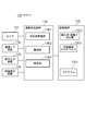
- FIG. 1 is a block diagram of an object management system according to the first embodiment of the present invention.
- the object management system 100 shown in FIG. 1 is a system that manages individual objects 150 such as products, commodities, and home deliveries for source display, quality control, distribution control, and the like.
- the object management system 100 includes a mobile terminal 110, a ballpoint pen 120 with a seal, and a server 130.
- the mobile terminal 110 and the server 130 are connected to each other so as to be able to communicate with each other through a network 140 such as the Internet.
- a network 140 such as the Internet.
- the ballpoint pen 120 with a seal is an example of a tool for forming a seal imprint and handwritten characters on a label 151 affixed to the surface of an object 150 to be managed.
- handwritten characters also include handwritten symbols and patterns.
- the label 151 is, for example, a high-quality paper having a rectangular flat shape coated with an adhesive, and can be easily attached to an arbitrary surface of the object 150 by pressing the back surface against the object 150 and adhering the label 151. You can do it.
- the seal imprint and the handwritten character are formed on the label 151 attached to the object 150, but the seal imprint and the handwritten character may be formed directly on the surface of the object 150.
- the ballpoint pen 120 with a seal has a structure in which the ballpoint pen 121 and the penetration mark 122 are combined into one.
- ink has penetrated into the printing surface 122a, and when the printing surface 122a is pressed against the surface of the label 151, an imprint corresponding to the pattern formed on the printing surface 122a is formed on the surface of the label 151.
- the penetrating stamp 122 used in the present embodiment is configured to form a stamp imprint having a shape in which characters representing an individual's sex are surrounded by a perfect circle outline.
- the ballpoint pen 121 is for writing arbitrary characters on the surface of the label 151.
- FIG. 2A shows an example of an image of the label 151 attached to the object 150 taken from the front.
- the label 151 of this example is formed with an imprint in which characters representing an individual's surname are surrounded by a perfect circle.
- the characters representing the surname are "samples" for convenience of explanation.
- the handwritten character "A" is written on the upper right of the imprint.
- an image in which the imprint of the seal stamp and the handwritten characters formed on the label 151 attached to the object 150 as described above are simultaneously copied is used as individual identification information for identifying the individual of the object 150.
- the individual identification power can be enhanced as compared with the image containing only the imprint or the image containing only the handwritten characters.
- the individual identification ability can be further enhanced by the variation in the relative positional relationship between the imprint and the handwritten characters.
- FIG. 2B shows an example of an image in which the same label 151 as in FIG. 2A is taken from an oblique direction.
- FIG. 2C shows an example of an image in which the same label 151 as in FIG. 2A is taken from an oblique direction different from that in FIG. 2B.
- the pattern of imprints and handwritten characters formed on one object 150 for object identification closely resembles the pattern of imprints and handwritten characters formed on another object 150 for object identification. The phenomenon occurs. As a result, the accuracy of object collation with images including imprints and handwritten characters is reduced.
- the distortion due to the projection is corrected and then registered and collated, so that the accuracy of the object collation is improved by the influence of the projection distortion. Prevent it from dropping.
- the method for correcting the projection distortion adopted in the present embodiment will be described.
- Equation 1 the planar projective transformation is represented by Equation 1 shown in FIG.
- x and y are the coordinates before conversion
- x'and y' are the coordinates after conversion
- a, b, c, d, e, f, g and h are projective conversion coefficients.
- the ellipse is detected from the image by taking a circle which is the outline of the imprint drawn on the plane at an angle and the ellipse is taken, and the coordinates of the four points on the detected ellipse before and after the conversion are obtained. Substitute in Equation 1 to obtain the projective conversion coefficient. Then, as the above four points, the four vertices of the square inscribed in the original circle are used.
- FIG. 4 is a schematic diagram showing the relationship between an ellipse obtained when a perfect circle drawn on a plane is photographed at an angle and a square inscribed in the original perfect circle.
- a square inscribed in the original perfect circle is a square in which two vertices P and Q facing each other coincide with both end points of the minor axis of the ellipse.
- the remaining two vertices R and S of the square do not coincide with the end points of the long axis of the ellipse.
- the center of the ellipse when the circle is viewed from an angle generally does not coincide with the center of the original circle. That is, the center of the original perfect circle moves in the depth direction of the minor axis by a certain distance ⁇ . Therefore, the problem is how to calculate the remaining two vertices R and S of the square.
- Non-Patent Document 1 describes a method of calculating the points of contact where a straight line passing through the intersection of the vanishing line on the image and the extension line of the minor axis of the ellipse touches the ellipse as vertices R and S.
- this method requires finding at least two vanishing points on the image to determine the vanishing points on the image. Since the vanishing point cannot be obtained from the circle alone, it is necessary to draw a figure such as a parallelogram on the object separately from the circle.
- the distance ⁇ between the center of the ellipse and the center of the original circle when the circle is viewed from an angle is treated as a variable depending on the feature amount of the ellipse, and various ellipses having different feature amounts are treated in advance.
- the eccentricity is used as the feature amount of the ellipse.
- the feature amount of the ellipse is not limited to the eccentricity, and other feature amounts such as the flatness may be used.
- a ratio to a predetermined reference length is used instead of an absolute value.
- the length of the minor axis of the ellipse is used as the reference length.
- the reference length is not limited to the minor axis, and an elliptical major axis or the like may be used. Details of the method for obtaining the distance ⁇ in advance will be described later.
- the mobile terminal 110 is a portable terminal such as a smartphone used for registering and collating an object to be managed.
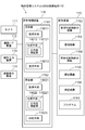
- FIG. 5 is a block diagram of the mobile terminal 110.
- the mobile terminal 110 includes a camera 111, a communication interface (I / F) device 112, an operation input device 113, a screen display device 114, a storage device 115, and an arithmetic processing unit 116. Has been done.
- the camera 111 is an imaging device that captures an object to be managed.
- the camera 111 is, for example, a visible light and color camera equipped with a CCD (Charge-Coupled Device) image sensor and a CMOS (Complementary MOS) image sensor having a pixel capacity of about several million pixels.
- the camera 111 also has a fixed aperture value and focal length.
- the communication I / F device 112 is composed of a data communication circuit, and is configured to wirelessly perform data communication with an external device such as a server 130.
- the operation input device 113 is composed of devices such as a keyboard and a mouse, and is configured to detect an operator's operation and output it to an arithmetic processing unit 116.
- the screen display device 114 is composed of a device such as an LCD (Liquid Crystal Display), and is configured to display various information on the screen in response to an instruction from the arithmetic processing device 116.
- the storage device 115 is composed of a storage device such as a hard disk or a memory, and is configured to store processing information and a program 1151 required for various processes in the arithmetic processing unit 116.
- the program 1151 is a program that realizes various processing units by being read and executed by the arithmetic processing unit 116, and is transmitted from an external device or recording medium (not shown) via a data input / output function such as a communication I / F device 112. It is read in advance and stored in the storage device 115.
- the main processing information stored in the storage device 115 includes an image 1152 of the object to be registered, an image 1153 registered, an image 1154 of the object to be collated, a collation image 1155, and a determination result 1156.
- the image 1152 of the object to be registered is an image of the label 151 affixed to the object to be registered taken by the camera 111.
- the registered image 1153 is an image 1152 of the object to be registered after correcting the distortion due to projection.
- the registered image 1153 is registered in the server 130 as data for determining the identity of the object to be registered.
- the image 1154 of the object to be collated is an image taken by the camera 111 of the label attached to the object to be collated.
- the image 1154 of the collation target object is distorted by projection, as in the image 1152 of the registration target object.
- the collation image 1155 is an image 1154 of the object to be collated after correcting the distortion due to projection.
- the determination result 1156 is data indicating whether or not the collation target object specified by the collation image 1155 is the same as any registration target object registered in the server 130.
- the arithmetic processing unit 116 has a processor such as an MPU and its peripheral circuits, and by reading and executing the program 1151 from the storage device 115, the hardware and the program 1151 cooperate with each other to realize various processing units. It is configured as follows.
- the main processing units realized by the arithmetic processing unit 116 are the registration unit 1161 and the collation unit 1162.
- the registration unit 1161 is configured to generate registration data including a registration image for determining the identity of the object to be registered and send it to the server 130.
- the registration unit 1161 includes acquisition means 11611, generation means 11612, and registration means 11613.
- the acquisition means 11611 is configured to acquire an image of the object to be registered from the camera 111 and store it in the storage device 115 as an image 1152 of the object to be registered.
- the generation means 11612 is configured to read the image 1152 of the object to be registered from the storage device 115 and detect the ellipse corresponding to the contour of the imprint from the image 1152. Further, the generation means 11612 is configured to generate an image obtained by projecting and transforming the image 1152 so that the detected ellipse becomes a perfect circle as a registered image 1153 and store it in the storage device 115. Even if the generation means 11612 is configured to extract a partial region of a predetermined size determined with reference to the center of the perfect circle as the registered image 1153 from the image obtained by projecting and transforming the image 1152 so that the ellipse becomes a perfect circle. Good.
- the registration means 11613 is configured to input additional information related to registration from the operation input device 113.
- the additional information is not particularly limited as long as it is information related to the object to be registered.
- the additional information may include, for example, the management number of the object to be registered, the registration date and time, and information indicating the contents of the object.
- the registration means 11613 is configured to read the registration image 1153 from the storage device 115, create registration data including the registration image 1153 and the additional information input above, and transmit the registration data to the server 130 through the communication I / F device 112. Has been done.
- the collation unit 1162 is configured to determine whether or not the object to be collated is the same as the object to be registered registered in the server 130.
- the collation unit 1162 includes an acquisition unit 11621, a generation unit 11622, and a determination unit 11623.
- the acquisition means 11621 is configured to acquire an image of the object to be collated from the camera 111 and store it in the storage device 115 as an image 1154 of the object to be collated.
- the generation means 11622 is configured to read an image 1154 of the collation target object from the storage device 115 and detect an ellipse corresponding to the contour of the imprint from the image 1154. Further, the generation means 11622 is configured to generate an image obtained by projecting and transforming the image 1154 so that the detected ellipse becomes a perfect circle as a collation image 1155 and store it in the storage device 115. Even if the generation means 11622 is configured to extract a partial region of a predetermined size determined with reference to the center of the perfect circle as the collation image 1155 from the image obtained by projecting and transforming the image 1154 so that the ellipse becomes a perfect circle. Good.
- the determination means 11623 is configured to read the collation image 1155 from the storage device 115. Further, the determination means 11623 transmits a registration data acquisition request to the server 130 through the communication I / F device 112, and receives the registration data which is a response of the acquisition request from the server 130 through the communication I / F device 112. It is configured in. Further, the determination means 11623 compares the registered image included in the registered data with the collated image 1155 for each received registered data, so that the collated object related to the collated image 1155 is the same as the registered object related to the registered data. It is configured to determine whether or not it is.
- the determination means 11623 when it is determined that the collation target object related to the collation image 1155 is the same as any of the registration target objects, the determination means 11623 includes additional information included in the registration data of the registration target object determined to be the same. The determination result 1156 is created and stored in the storage device 115. Further, when the determination means 11623 determines that the collation target object related to the collation image 1155 is not the same as any of the registration target objects, the determination means 11623 creates a determination result 1156 indicating that the same registration target object does not exist, and stores the storage device 115. It is configured to save. Further, the determination means 11623 is configured to read the determination result 1156 from the storage device 115, display it on the screen of the screen display device 114, or / and transmit it to an external terminal through the communication I / F device 112.
- FIG. 6 is a block diagram of the server 130.
- the server 130 includes a camera 131, a communication interface (I / F) device 132, an operation input device 133, a screen display device 134, a storage device 135, and an arithmetic processing unit 136. ing.
- the camera 131 is a camera having the same specifications as the camera 111 of the mobile terminal 110.
- the communication I / F device 132 is composed of a data communication circuit, and is configured to wirelessly perform data communication with an external device such as a mobile terminal 110.
- the operation input device 133 is composed of devices such as a keyboard and a mouse, and is configured to detect an operator's operation and output it to an arithmetic processing unit 136.
- the screen display device 134 is composed of a device such as an LCD, and is configured to display various information on the screen in response to an instruction from the arithmetic processing unit 136.
- the storage device 135 is composed of a storage device such as a hard disk or a memory, and is configured to store processing information and a program 1351 necessary for various processes in the arithmetic processing unit 136.
- the program 1351 is a program that realizes various processing units by being read and executed by the arithmetic processing unit 136, and is transmitted from an external device or recording medium (not shown) via a data input / output function such as a communication I / F device 132. It is read in advance and stored in the storage device 135.
- the main processing information stored in the storage device 135 includes the eccentricity / distance ⁇ correspondence table 1352 and the registered image database 1353.
- Correspondence table 1352 of eccentricity and distance ⁇ is configured to store the correspondence between the eccentricity of the ellipse and the distance ⁇ explained with reference to FIG.
- FIG. 7 shows an example of the eccentricity / distance ⁇ correspondence table 1352.
- the eccentricity / distance ⁇ correspondence table 1352 of this example is composed of a plurality of entries, and one entry is composed of an eccentricity range column and a distance ⁇ column.
- a certain eccentricity range when the eccentricity of 0 or more and less than 1 is divided into a plurality of eccentricity ranges, and the distance corresponding to the eccentricity range. ⁇ is set.
- the method of dividing the eccentricity of 0 or more and less than 1 into a plurality of eccentricity ranges is arbitrary.
- the eccentricity of 0 or more and less than 1 is evenly divided by 0.1, and the eccentricity range of 0 or more and less than 0.1, the eccentricity range of 0.1 or more and less than 0.2, ... , 0.9 or more and less than 1.0.
- the unit to be divided is not limited to 0.1.
- the eccentricity of 0 or more and less than 1 may be divided into uneven widths.
- the registered image database 1353 is configured to store images of objects to be registered and additional information.
- FIG. 8 is a diagram showing an example of the contents of the registered image database 1353.
- the registered image database 1353 of this example is composed of a plurality of entries, and one entry is composed of a registration number column, a registered image column, and an additional information column.
- the registered image and additional information of a certain object to be registered are stored in the registered image column and the additional information column of the same entry.
- In the registration number field a serial number that uniquely identifies the entry is stored.
- the arithmetic processing unit 136 has a processor such as an MPU and its peripheral circuits, and by reading and executing the program 1351 from the storage device 135, the hardware and the program 1351 are made to cooperate to realize various processing units. It is configured as follows.
- the main processing units realized by the arithmetic processing unit 136 are the correspondence table management unit 1361, the registration unit 1362, and the collation unit 1363.
- the correspondence table management unit 1361 shows the correspondence between the eccentricity of the ellipse and the distance ⁇ based on the results of analyzing a plurality of images of the circle drawn on the plane taken by the camera 131 from various angles. Is generated and stored in the storage device 135 as the eccentricity / distance ⁇ correspondence table 1352.
- the correspondence table management unit 1361 receives a request for acquiring the distance ⁇ from the mobile terminal 110 that specifies the eccentricity of the ellipse, it searches the eccentricity / distance ⁇ correspondence table 1352 and transfers the corresponding distance ⁇ to the mobile terminal 110. It is configured to send.
- the registration unit 1362 When the registration unit 1362 receives a registration data registration request from the mobile terminal 110 through the communication I / F device 132, the registration unit 1362 secures one free entry in the registration image database 1353, and the registration image and additional information included in the received registration request. Is configured to be saved in the registration image field and additional information field of the empty entry. Further, the registration unit 1362 is configured to assign a new registration number and store it in the registration number field of an empty entry.
- the collation unit 1363 When the collation unit 1363 receives the registration data acquisition request from the mobile terminal 110 through the communication I / F device 132, the collation unit 1363 reads the registration data registered in each entry of the registered image database 1353 and carries the registration data through the communication I / F device 132. It is configured to transmit to the terminal 110.
- the operation of the object management system 100 is roughly classified into a pre-operation, a registration operation, and a collation operation.
- the pre-operation is an operation for creating the eccentricity / distance ⁇ correspondence table 1352.
- the registration operation is an operation of registering an image of an object to be registered as a registration image.
- the collation operation is an operation of collating the image of the collation target object with the registered image.
- the pre-operation is performed by the operator of the server 130 and the correspondence table management unit 1361 prior to the registration operation and the collation operation.
- FIG. 9 is a flowchart showing an example of the procedure for creating the eccentricity / distance ⁇ correspondence table 1352.
- the operator prepares a paper in which the circle and the center point of the circle are drawn in a color different from the background color (step S1).
- inspection paper will be referred to as inspection paper.
- FIG. 10 is a plan view showing an example of inspection paper.
- the circle drawn on the inspection paper assumes the outline of the seal. Therefore, the diameter of the circle drawn on the inspection paper is equal to the diameter of the outline of a general stamp. However, the diameter of the circle may be longer or shorter than the diameter of the outline of a general stamp.
- the center point of the circle drawn on the inspection paper is a dot.
- the operator puts the inspection paper on a flat table with the circled side facing up, and uses the camera 131 under appropriate lighting to make the circle almost while changing the shooting direction in various ways.
- the inspection paper is repeatedly photographed so as to be reflected in the center (step S2).
- the correspondence table management unit 1361 acquires the shot image of the inspection paper from the camera 131 as an inspection image and temporarily saves it (step S3).
- the operator may set the camera 131 in the still image mode and repeat the operation of shooting the still image from various shooting directions.
- the correspondence table management unit 1361 acquires one still image taken by the camera 131 as one inspection image.
- the operator may set the camera 131 to the moving image mode and shoot a moving image while changing the shooting direction in various ways.
- the correspondence table management unit 1361 acquires the frame image of the moving image taken by the camera 131 as one inspection image.
- the correspondence table management unit 1361 extracts the ellipse and the center point of the circle for each inspection image (step S4).
- the correspondence table management unit 1361 extracts an ellipse by, for example, applying an ellipse to a sequence of points extracted from an inspection image. That is, the equation of the ellipse existing in the image is obtained. However, other ellipse detection methods such as the Hough transform method may be used. Further, the correspondence table management unit 1361 extracts the dots existing inside the extracted ellipse as the center points of the circle.
- the correspondence table management unit 1361 calculates the feature amount of the ellipse (eccentricity in this example) and the center of the ellipse for each inspection image (step S5). Next, the correspondence table management unit 1361 calculates the distance ⁇ between the center of the ellipse and the center of the circle on the inspection image for each inspection image (step S6). Next, the correspondence table management unit 1361 creates an eccentricity / distance ⁇ correspondence table 1352 from the eccentricity and the distance ⁇ of the ellipse calculated for each inspection image, and stores it in the storage device 135 (step S7).
- the correspondence table management unit 1361 first classifies the pair of the eccentricity of the ellipse and the distance ⁇ calculated for each inspection image into groups for each eccentricity range based on the eccentricity of the ellipse. Next, the correspondence table management unit 1361 calculates the average value of the distance ⁇ possessed by the pair belonging to the group for each group, and sets the average value and the eccentricity range of the group as 1 of the eccentricity / distance ⁇ correspondence table 1352. Create as the distance ⁇ of one entry and the eccentricity range.
- FIG. 11 is a flowchart showing an example of the procedure of the registration operation.
- the operator of the mobile terminal 110 uses a ballpoint pen 120 with a seal stamp to attach a label 151 on which the imprint and handwritten characters are written to the object 150 to be registered (step S11).
- the operator operates the mobile terminal 110 to take an image of the label 151 with the camera 111 so that the imprint on the label 151 and the handwritten characters are substantially centered (step S12).
- the acquisition means 11611 of the registration unit 1161 of the mobile terminal 110 acquires the captured image of the label 151 from the camera 111 and stores it in the storage device 115 as an image 1152 of the object to be registered (step S13).
- the generation means 11612 of the registration unit 1161 of the mobile terminal 110 reads the image 1152 of the object to be registered from the storage device 115, and detects the ellipse corresponding to the contour of the imprint from the image (step S14).
- the generation means 11612 extracts an ellipse by, for example, applying an ellipse to a sequence of points extracted from the image 1152 of the object to be registered. That is, the equation of the ellipse existing in the image is obtained.
- other ellipse detection methods such as the Hough transform method may be used.
- the generation means 11612 generates an image obtained by projecting and transforming the entire image 1152 of the object to be registered so that the detected ellipse becomes a perfect circle as the registered image 1153, and stores it in the storage device 115 (step S15).
- the registration means 11613 of the registration unit 1161 of the mobile terminal 110 inputs additional information related to registration from the operator through the operation input device 113, and registers including the registration image 1153 read from the storage device 115 and the input additional information.
- a request is created and transmitted to the server 130 through the communication I / F device 112 (step S16).
- the registration unit 1362 of the server 130 receives the registration request from the mobile terminal 110 through the communication I / F device 132, and saves the registration request as new registration data in the registered image database 1353 (step S17).
- FIG. 12 is a flowchart showing a detailed procedure of step S15 of FIG.
- the generation means 11612 of the mobile terminal 110 calculates the eccentricity of the ellipse detected in step S14, and acquires the distance ⁇ corresponding to the eccentricity from the server 130 (step S21). Specifically, first, the generation means 11612 transmits a request for acquiring the distance ⁇ including the eccentricity to the server 130 through the communication I / F device 112.
- the correspondence table management unit 1361 of the server 130 acquires the distance ⁇ from the entry in the correspondence table 1352 having the divergence rate included in the acquisition request received from the mobile terminal 110 within the divergence rate range, and the distance ⁇ .
- the acquisition result including the above is transmitted to the mobile terminal 110 through the communication I / F device 132.
- the generation means 11612 of the mobile terminal 110 acquires the distance ⁇ from the received acquisition result.
- Step S22 the generation means 11612 determines the intersection of the straight line passing through the center of the original circle and parallel to the long axis of the ellipse and the ellipse at the two vertices R and S of the square inscribed in the original circle (step S23).
- step S24 the generation means 11612 determines both ends of the minor axis of the ellipse as two vertices P and Q of a square inscribed in the original circle (step S24).
- the generation means 11612 solves an eight-element simultaneous equation in which the coordinates before and after the conversion of the vertices P, Q, R, and S are substituted into the equation 1 to calculate the projective transformation coefficient (step S25).
- the generation means 11612 uses the calculated projective transformation coefficient to project-transform the entire image 1152 of the object to be registered to generate the registered image 1153 (step S26).
- FIG. 13 is a flowchart showing an example of the procedure of the collation operation.
- the operator of the mobile terminal 110 operates the mobile terminal 110 to take an image of the label 151 with the camera 111 so that the imprint and the handwritten characters on the label 151 attached to the object to be collated are captured in the center (the camera 111).
- Step S31 the acquisition unit 11621 of the collation unit 1162 of the mobile terminal 110 acquires the captured image of the label 151 from the camera 111 and stores it in the storage device 115 as an image 1154 of the collation target object (step S32).
- the generation means 11622 of the collation unit 1162 of the mobile terminal 110 reads the image 1154 of the collation target object from the storage device 115, and corresponds to the contour of the imprint from the image by the same method as the generation means 11612 of the registration unit 1161.
- the ellipse is detected (step S33).
- the generation means 11622 generates an image obtained by projecting and transforming the entire image 1154 of the collation target object as a collation image 1155 so that the detected ellipse becomes a perfect circle by the same method as the generation means 11612 of the registration unit 1161. , Stored in the storage device 115 (step S34).
- the determination means 11623 of the collation unit 1162 of the mobile terminal 110 reads the collation image 1155 from the storage device 115 and compares the collation image 1155 with the registered image registered in the server 130 to match the collation target object.
- the identity of the object to be registered is determined, and the determination result 1156 is stored in the storage device 115 (step S35).
- the determination means 11623 transmits a registration data acquisition request to the server 130 through the communication I / F device 112.
- the collating unit 1363 of the server 130 receives the acquisition request from the mobile terminal 110 through the communication I / F device 132, it reads out all the registered data stored in the registered image database 1353 and passes through the communication I / F device 132.
- the determination means 11623 receives all the registration data transmitted from the server 130 through the communication I / F device 112, the determination means 11623 compares the registration image included in the registration data with the collation image 1155 for each registration data to obtain an object. Perform collation. Next, the determination means 11623 reads the determination result 1156 from the storage device 115, displays it on the screen display device 114, and / and outputs it to the external device through the communication I / F device 112 (step S36).
- FIG. 14 is a flowchart showing an example of a procedure for collating the collated image with the registered image.
- the determination means 11623 first performs frequency conversion, polar coordinate conversion, logarithmic polar coordinate conversion, and frequency conversion on the collated image in that order to calculate the collated feature amount (step S41).
- An image obtained by performing frequency conversion such as Fourier transform on a collated image is called a frequency spectrum image.
- a feature quantity obtained by subjecting the frequency spectrum image to polar coordinate transformation or logarithmic polar coordinate transformation is called a Fourier-merin feature.
- a feature quantity obtained by performing a frequency transform such as a Fourier transform on the Fourier-merin feature is called a Fourier-merin frequency spectrum image. This Fourier-merin frequency spectrum image is invariant to the magnification, rotation, and translation of the captured image.
- the determination means 11623 performs frequency conversion, polar coordinate conversion, or logarithmic polar coordinate conversion, and frequency conversion in that order on each registered image in the same manner as the collation image, and calculates the registered feature amount (step S42).
- the determination means 11623 calculates a cross power spectrum between the collation feature amount and each registered feature amount (step S43).
- the determination means 11623 performs inverse frequency conversion of each cross power spectrum to calculate a correlation value map (step S44).
- the determination means 11623 calculates each collation score representing the degree of similarity between the collation image and each registered image from each correlation value map (step S45).
- the determination means 11623 determines the identity of the objects based on their collation scores (step S46).
- the determination means 11623 determines that the object related to the collation image is not registered unless the maximum value of the collation score is equal to or greater than the threshold value.
- the object management system 100 registers and collates the image of the imprint and the handwritten character formed on the object 150, it registers and collates after correcting the distortion due to the projection.
- the object management system 100 uses the fact that a circle, which is the outline of an imprint drawn on a plane, becomes an ellipse when photographed at an angle, detects an ellipse from the image, and makes the detected ellipse a circle. This is for projective conversion to.
- the center of the perfect circle of the imprint of the stamp in the image can be obtained even if the object does not have a figure such as a parallelogram for obtaining the vanishing point on the image.
- the object management system 100 has, for each of a plurality of images of a perfect circle taken from various angles, the feature amount of the ellipse (eccentricity in this example) corresponding to the circle in the image and the ellipse. This is because it has an eccentricity / distance ⁇ correspondence table that calculates the distance ⁇ between the center point and the point in the image corresponding to the center of the circle, and stores the feature amount of the ellipse and the distance ⁇ in advance.
- the object management system 200 according to the present embodiment recommends the types of characters to be handwritten on the label 151 affixed to the object 150 to be registered and the description position. It differs in that it has a function of presenting to the operator, and is the same as the object management system 100 according to the first embodiment except for the above.
- the character description position is defined based on the imprint. Specifically, the imprint is above, upper right, right, lower right, lower, lower left, left, upper left, and the like.
- FIG. 15 is a block diagram of the mobile terminal 110 according to the present embodiment, the same reference numerals as those in FIG. 5 indicate the same parts, and 11614 is a recommended means.
- the recommended means 11614 recommends to the operator of the mobile terminal 110 the type and position of characters to be described on the label 151 attached to the object 150 to be registered before the acquisition means 11611 acquires the image of the object to be registered. It is structured to present a proposal.
- the recommendation means 11614 is configured to obtain a proposal to be presented to the operator from the server 130.
- FIG. 16 is a block diagram of the server 130 according to the present embodiment, the same reference numerals as those in FIG. 6 indicate the same parts, 1354 is a recommended proposal database, and 1364 is a recommended means.
- the recommendation proposal database 1354 is configured to store a plurality of combinations of character types and description positions in advance.
- the recommended means 1364 is configured to acquire a combination of unused character types and description positions from the recommended draft database 1354 and provide it to the recommended means 11614 of the mobile terminal 110.
- FIG. 17 shows an example of the contents of the recommended proposal database 1354.
- the proposed proposal database 1354 of this example is composed of a plurality of entries, and one entry has columns for surname, character description position, character, and presence / absence of use.
- the surname column the surname used for the seal is stored.
- the recommended character description position is stored in the character description position column.
- the recommended character type is stored in the character field.
- the use / non-use column the history of whether or not it has been used in the past is stored. For example, in the use / non-use column, a value 0 is stored if it has not been used in the past, and a value 1 is stored if it has been used in the past.
- FIG. 18 is a flowchart showing an example of a procedure for presenting a recommended proposal to the operator.
- the operator of the mobile terminal 110 inputs the surname of the seal to be used from now on from the operation input device 113 before writing the imprint and the handwritten character on the label 151, and requests a recommended character type and description position (Ste S51).
- the recommended means 11614 of the mobile terminal 110 transmits a request for acquisition of the recommended proposal including the input surname to the server 130 through the communication I / F device 112 (step S52).
- the recommended means 1364 of the server 130 has the same surname as the surname included in the acquisition request from the entries in the recommended proposal database 1354, and the use / non-use column has a value of 0 indicating unused. Search the entry, make a recommendation including the characters described in the character field in the entry and the character description position described in the character description position column, and indicate used in the presence / absence column in the entry. The value 1 is stored and the recommended proposal is transmitted to the mobile terminal 110 (step S53).
- the recommended means 11614 of the mobile terminal 110 generates an image of the recommended proposal drawn at the recommended character description position with the sample imprint and the recommended character according to the character type and the character description position acquired from the server 130 (step). S54). Then, the recommended means 11614 displays the image of the recommended proposal on the screen display device 114 (step S55).
- FIG. 19 shows an example of a recommended image displayed on the screen display device 114 of the mobile terminal 110.
- it is recommended to write the letter "A" in the upper left of the imprint.
- the operator of the mobile terminal 110 can know the type of characters having individual discriminating power to be described on the label 151 and the description position thereof by visually confirming the recommended proposal displayed on the screen display device 114. Subsequent registration operations are the same as the registration operations in the first embodiment.
- the individual discriminating power of the image including the figure and the character can be enhanced. As a result, the accuracy of object collation can be further improved.
- the object management system 200 presented a recommended combination of character types and description positions.
- the object management system 200 may be configured to present only recommendations for character types.
- the object management system 200 may be configured to present a recommended proposal only for the character description position.
- the recommendation proposal database 1354 is configured to store the recommendation proposals of the character type and the character description position for each surname included in the imprint.
- the recommended draft database 1354 may be configured to store the recommended draft of the character type and the character description position in common to all imprints.
- the object management system 300 according to the present embodiment has already stored the registered image and the registered image database 1353 before writing the registered image to the registered image database 1353.
- a collation score indicating the degree of similarity with the registered image is calculated, and based on the collation score, it is decided whether or not to write the registered image to the registered image database 1353, and when the registered image is not written, The difference is that the user is urged to add more characters and redo the registration operation, and other than that, it is the same as the object management system 100 according to the first embodiment.
- FIG. 20 is a block diagram of the server 130 according to the present embodiment, and the same reference numerals as those in FIG. 6 indicate the same parts, and 13621 is a registration possibility determination unit.
- the registration possibility determination unit 13621 sets a collation score indicating the similarity between the registered image and all the registered images already stored in the registered image database 1353. It is configured to calculate. Further, the registration possibility determination unit 13621 is configured to determine whether or not to write the registered image to the registered image database 1353 based on all the calculated collation scores.
- the registration possibility determination unit 13621 is configured to determine not to register if the maximum value of all the collation scores is equal to or greater than a predetermined threshold value, and to determine otherwise.
- the threshold value is set to a value that is the same as or slightly smaller than the threshold value at which the collation unit 1363 determines the identity of the object.
- the registration possibility determination unit 13621 is configured to instruct the registration unit 1362 to write the registered image to the registered image database 1353 when it is determined to register.
- the registration possibility determination unit 13621 is configured to stop the operation of registering the registered image in the registered image database 1353 and send the re-registration operation request message to the mobile terminal 110.
- the screen display device 114 is configured to display a guidance screen prompting the user to perform the registration operation again with further description.
- FIG. 21 is a flowchart showing an example of the procedure of the registration operation.
- a registration request including the registered image 1153 and additional information is transmitted from the mobile terminal 110 to the server 130 from step S11 in which the label 151 having the imprint and the handwritten characters is attached to the object 150 to be registered.
- the procedure up to this point is the same as the procedure at the time of registration in the first embodiment shown in FIG.
- the registration possibility determination unit 13621 calculates a collation score between the registered image and all the registered images in the registered image database 1353 (step S61). ..
- the collation score for example, first, the Fourier merin frequency features of the images to be collated with each other are calculated, then the cross power spectrum between the features is calculated, and then the inverse frequency conversion is performed to perform the correlation value. This can be done by calculating a map and then calculating a collation score representing the degree of similarity between the registered image and the registered image from the correlation value map.
- the server 130 determines whether or not to write the registered image to the registered image database 1353 based on all the calculated collation scores by the registration availability determination unit 13621 (step S62).
- the registration unit 1362 registers the registration data including the registration image in the registration image database 1353 (step S64).
- the server 130 transmits the re-registration operation request to the mobile terminal 110 (step S65).
- the mobile terminal 110 displays a re-registration guidance screen on the screen display device 114 to urge the user to repeat the registration operation by adding a further description near the imprint (step S66).
- FIG. 22 is a diagram showing an example of a re-registration guidance screen displayed on the screen display device 114 of the mobile terminal 110.
- the message "Insufficient individual discriminating power. Please add more handwritten characters and try the registration operation again.” Is displayed.
- the operator of the mobile terminal 110 can know that the re-registration operation must be performed, and at that time, further characters must be added.
- a message prompting to add more handwritten characters was displayed on the re-registration guidance screen.
- a message prompting the increase in the number of imprints of the seal stamp may be displayed on the re-registration guidance screen.
- a message prompting the addition of the number of handwritten characters and imprints may be displayed on the re-registration guidance screen.
- the object management system 400 according to the present embodiment calculates the roundness of the contour of the imprint extracted from the image of the object to be registered and the image of the object to be collated as compared with the object management system 100 according to the first embodiment. However, if the roundness is equal to or higher than a predetermined threshold value, the difference is that the image of the object to be registered and the image of the object to be collated are configured so as to be regarded as having almost no distortion due to projection. Other than that, it is the same as the object management system 100 according to the first embodiment.
- FIG. 23 is a block diagram of the mobile terminal 110 according to the present embodiment, the same reference numerals as those in FIG. 5 indicate the same parts, and 116121 and 116221 are roundness verification units.
- the roundness verification unit 116121 is configured to calculate the roundness of the ellipse corresponding to the contour of the imprint extracted from the image of the object to be registered.
- the degree of perfect circle is an index value indicating the degree of deviation from the perfect circle.
- the roundness of an ellipse can be expressed as a value by subtracting the eccentricity of the ellipse from 1. In this case, the closer the ellipse is to the circle, the closer the roundness of the ellipse is to 1.
- the roundness verification unit 116121 is configured to determine whether or not to treat the image of the object to be registered as a registered image based on the result of comparing the roundness of the ellipse with a preset threshold value. There is. Assuming that the threshold value is 0.9, for example, the roundness verification unit 116121 treats the image of the object to be registered as a registered image if the roundness of the ellipse is 0.9 or more.
- the roundness verification unit 116221 is configured to calculate the roundness of the ellipse corresponding to the contour of the imprint extracted from the image of the collation target object. Further, the roundness verification unit 116221 is configured to determine whether or not to treat the image of the collation target object as a collation image based on the result of comparing the roundness of the ellipse with a preset threshold value. There is.
- FIG. 24 is a flowchart showing an example of the procedure of the registration operation.
- the procedure from step S11 of attaching the label 151 on which the imprint and the handwritten characters are described to the object 150 to be registered to step S14 of extracting the ellipse corresponding to the outline of the imprint from the image of the object to be registered. Is the same as the procedure at the time of registration in the first embodiment shown in FIG.
- the mobile terminal 110 calculates the roundness of the extracted ellipse by the roundness verification unit 116121 (step S71).
- the mobile terminal 110 compares the calculated roundness with the threshold value by the roundness verification unit 116121 (step S72).
- the mobile terminal 110 treats the image of the object to be registered as a registered image (step S73), and proceeds to step S16. If the roundness is less than the threshold value, the mobile terminal 110 proceeds to step S15.
- Steps S15 to S17 are the same as steps S15 to S17 at the time of registration in the first embodiment shown in FIG.
- FIG. 25 is a flowchart showing an example of the procedure of the collation operation.
- the procedure from step S31 for acquiring the image of the label attached to the collation target object to step S33 for detecting the ellipse corresponding to the contour of the imprint from the image of the collation target object is shown in FIG. It is the same as the procedure at the time of collation in the first embodiment shown.
- the mobile terminal 110 calculates the roundness of the extracted ellipse by the roundness verification unit 116221 (step S81).
- the mobile terminal 110 compares the calculated roundness with the threshold value by the roundness verification unit 116221 (step S82).
- the mobile terminal 110 treats the image of the collation target object as a collation image (step S83), and proceeds to step S35. If the roundness is less than the threshold value, the mobile terminal 110 proceeds to step S34.
- Steps S34 to S36 are the same as steps S34 to S36 at the time of collation in the first embodiment shown in FIG.
- the roundness of the outline of the imprint extracted from the image of the registration target object and the image of the collation target object is calculated, and the image of the registration target object and the collation target object are calculated based on the roundness.
- the roundness of the outline of the imprint extracted from the image of the object to be registered is less than the threshold value, a registered image corrected for distortion due to projection is generated and registered.
- the image of the object to be registered is discarded and the user is instructed to retake the image of the label from the front.
- the screen may be configured to be displayed on the screen display device 114.
- the roundness of the contour of the imprint extracted from the image of the collation target object is less than the threshold value, a collation image corrected for distortion due to projection is generated and registered.
- the image of the collation target object is discarded and the user is instructed to retake the label image from the front.
- the screen may be configured to be displayed on the screen display device 114.
- the object management system 500 is composed of an acquisition means 501, a generation means 502, and a registration means 503.
- the acquisition means 501 is configured to acquire an image of the surface of the object to be registered in which a circle and handwritten characters are drawn.
- the acquisition means 501 can be configured in the same manner as, for example, the acquisition means 11611 of FIG. 5, but is not limited thereto.
- the generation means 502 is configured to detect an ellipse corresponding to the circle from the image acquired by the acquisition means 501 and generate a registered image obtained by projecting and transforming the image so that the ellipse becomes a circle. ..
- the generation means 502 can be configured in the same manner as, for example, the generation means 11612 of FIG. 5, but is not limited thereto.
- the registration means 503 is configured to write the registered image generated by the generation means 502 into the storage means as data for determining the identity of the object to be registered.
- the registration means 503 can be configured in the same manner as, for example, the registration means 11613 of FIG. 5, but is not limited thereto.
- the object management system 500 configured as described above operates as follows. That is, first, the acquisition means 501 acquires an image obtained by photographing the surface of the object to be registered in which the circle and the handwritten character are drawn. Next, the generation means 502 detects an ellipse corresponding to the circle from the image acquired by the acquisition means 501, and generates a registered image obtained by projecting and transforming the image so that the ellipse becomes a circle. Next, the registration means 503 writes the registered image generated by the generation means 502 into the storage means as data for determining the identity of the object to be registered.
- the object management system 500 is configured and operates as described above, so that the accuracy of object matching using an image including figures and characters can be improved.
- the reason is that the generation means 502 detects an ellipse corresponding to a circle from the image acquired by the acquisition means 501, and generates a registered image obtained by projecting and transforming the image so that the ellipse becomes a circle.
- the object collation system 600 is composed of the acquisition means 601, the generation means 602, and the determination means 603.
- the acquisition means 601 is configured to acquire an image of the surface of the object to be collated on which the circle and the handwritten character are drawn.
- the acquisition means 601 can be configured in the same manner as, for example, the acquisition means 11621 of FIG. 5, but is not limited thereto.
- the generation means 602 is configured to detect an ellipse corresponding to the circle from the image acquired by the acquisition means 601 and generate a collation image obtained by projecting and transforming the image so that the ellipse becomes a circle. ..
- the generation means 602 can be configured in the same manner as, for example, the generation means 11622 of FIG. 5, but is not limited thereto.
- the determination means 603 compares the collation image generated by the generation means 602 with the registered image related to the object to be registered stored in the storage means, so that the object to be collated and the object to be registered are the same. Is configured to determine.
- the determination means 603 can be configured in the same manner as, for example, the determination means 11623 of FIG. 5, but is not limited thereto.
- the object collation system 600 configured as described above operates as follows. That is, first, the acquisition means 601 acquires an image obtained by photographing the surface of the object to be collated on which the circle and the handwritten character are drawn. Next, the generation means 602 detects an ellipse corresponding to the circle from the image acquired by the acquisition means 601 and generates a collation image obtained by projecting and transforming the image so that the ellipse becomes a circle. Next, the determination means 603 determines the object to be collated and the object to be registered by comparing the collation image generated by the generation means 602 with the registered image related to the object to be registered stored in the storage means. Determine identity.
- the object collation system 600 is configured and operates as described above, so that the accuracy of object collation using an image including figures and characters can be improved.
- the reason is that the generation means 602 detects an ellipse corresponding to a circle from the image acquired by the acquisition means 601 and generates a collation image obtained by projecting and transforming the image so that the ellipse becomes a circle.
- Non-Patent Document 1 may be used as a method of projecting and transforming an image so that an ellipse in the image becomes a circle.
- the points of contact where a straight line passing through the intersection of the vanishing line on the image and the extension of the minor axis of the ellipse touches the ellipse are calculated as the vertices R and S of the square inscribed in the original circle, and the minor axis of the ellipse.
- Both end points may be calculated as the vertices P and Q of the square, and the projection conversion coefficient may be calculated from the coordinates before and after the conversion of the vertices of the square.
- a plurality of figures such as a parallelogram may be drawn on the surface of the object to be registered in addition to the circle.
- the projective transformation coefficient may be calculated from the parameters of the ellipse in the image and the focal length of the camera.
- the position and orientation of the camera with respect to the center of the perfect circle are used by using a plurality of images (time series images) and the speed and acceleration of the camera. May be estimated using a Kalman filter to obtain the projective transformation coefficient.
- two or more perfect circles are drawn on the surface of the object to be registered, and the vanishing point is obtained from two or more ellipses corresponding to the two or more perfect circles in the image to obtain the projective conversion coefficient. May be good.
- the registered image stored in the registered image database 1353 is obtained by subjecting the registered image 1153 to frequency conversion, polar coordinate conversion, log polar coordinate conversion, and frequency conversion in that order. It may be a spectrum image.
- the circle drawn on the surface of the object to be registered may be a circle other than the outline of the imprint of the seal stamp.
- it may be a sticker in which a circle is drawn in a color different from the background.
- it may be a circle handwritten by the user with a pen using a circle template ruler or the like.
- a part of the processing executed by the mobile terminal 101 may be executed by the server 130.
- a part or all of the processes of steps S14 and S15 in FIG. 11, steps S33 to S35 in FIG. 13, steps S41 to S46 in FIG. 14, step S54 in FIG. 18, and steps S71 to S73 in FIG. 24 are performed by the server 130. It may be configured to run.
- a part or all of the processing executed by the server 130 may be executed by the mobile terminal 110.
- the mobile terminal 110 may be configured to perform a part or all of the processes of steps S1 to S7 in FIG. 9, steps S17 in FIG. 11, step S53 in FIG. 18, and steps S61 to S65 in FIG.
- the present invention can be used in fields such as traceability centered on C2C transactions and personal authentication centered on entrance / exit management.
- a first ellipse corresponding to the first circle is detected from the first image, and a registered image obtained by projecting and transforming the first image so that the first ellipse becomes a circle is generated.
- the object management system according to Appendix 1.
- the first circle is a circle that forms the outline of the imprint of the seal stamped on the surface.
- Appendix 4 Further provided is a recommended means for selecting a recommendation that has not yet been used from a plurality of recommendations that define a combination of a character type and a character description position and presenting it to the user.
- the object management system according to any one of Appendix 1 to 3.
- Appendix 5 Before writing the registered image, a collation score between the registered image and an image already stored in the storage means is calculated, and whether or not the registered image is written in the storage means based on the collation score. Further provided with a means for determining whether or not registration is possible.
- the object management system according to any one of Appendix 1 to 4.
- the registration possibility determination means is configured to guide the user to redo the registration operation by further adding a description on the object.
- the object management system according to Appendix 5.
- a roundness verification means for calculating the roundness of the first ellipse and determining whether or not to treat the first image as it is as the registered image based on the roundness.
- the object management system according to any one of Appendix 1 to 6.
- 2 generation means and A determination means for determining the identity between the collation target object and the registration target object by comparing the collation image with the registered image stored in the storage means is further provided.
- the object management system according to any one of Appendix 1 to 7.
- [Appendix 10] Acquire the first image of the surface of the object to be registered in which the first circle and the first handwritten character are drawn. A first ellipse corresponding to the first circle is detected from the first image, and a registered image obtained by projecting and transforming the first image so that the first ellipse becomes a circle is generated. The registered image is written in the storage means as data for determining the identity of the object to be registered.
- Object management method Acquire the first image of the surface of the object to be registered in which the first circle and the first handwritten character are drawn. A first ellipse corresponding to the first circle is detected from the first image, and a registered image obtained by projecting and transforming the first image so that the first ellips
- a generation that detects a first ellipse corresponding to the first circle from the first image and generates a collation image obtained by projecting and transforming the first image so that the first ellipse becomes a circle.
- Means and An object including a determination means for determining the identity between the collation target object and the registration target object by comparing the collation image with the registered image related to the registration target object stored in the storage means. Matching system.
- Object management system 110 ... Mobile terminal 111 ... Camera 112 ... Communication I / F device 113 ... Operation input device 114 ... Screen display device 115 ... Storage device 1151 ... Program 1152 ... Image of object to be registered 1153 ... Registered image 1154 ... Collation Image of target object 1155 ... Collation image 1156 ... Judgment result 116 ... Arithmetic processing device 1161 ... Registration unit 11611 ... Acquisition means 11612 ... Generation means 116121 ... Roundness verification unit 11613 ... Registration means 11614 ... Recommended means 1162 ... Collation unit 11621 ... Acquisition means 11622 ... Generation means 116221 ... Roundness verification unit 11623 ... Judgment means 120 ...
Landscapes
- Engineering & Computer Science (AREA)
- Physics & Mathematics (AREA)
- Computer Vision & Pattern Recognition (AREA)
- General Physics & Mathematics (AREA)
- Theoretical Computer Science (AREA)
- Multimedia (AREA)
- Human Computer Interaction (AREA)
- Geometry (AREA)
- Image Analysis (AREA)
- Collating Specific Patterns (AREA)
Priority Applications (3)
| Application Number | Priority Date | Filing Date | Title |
|---|---|---|---|
| PCT/JP2019/024786 WO2020255394A1 (ja) | 2019-06-21 | 2019-06-21 | 物体管理システム |
| JP2021528612A JP7197009B2 (ja) | 2019-06-21 | 2019-06-21 | 物体管理システム |
| US17/618,132 US11908214B2 (en) | 2019-06-21 | 2019-06-21 | Object management system |
Applications Claiming Priority (1)
| Application Number | Priority Date | Filing Date | Title |
|---|---|---|---|
| PCT/JP2019/024786 WO2020255394A1 (ja) | 2019-06-21 | 2019-06-21 | 物体管理システム |
Publications (1)
| Publication Number | Publication Date |
|---|---|
| WO2020255394A1 true WO2020255394A1 (ja) | 2020-12-24 |
Family
ID=74040427
Family Applications (1)
| Application Number | Title | Priority Date | Filing Date |
|---|---|---|---|
| PCT/JP2019/024786 Ceased WO2020255394A1 (ja) | 2019-06-21 | 2019-06-21 | 物体管理システム |
Country Status (3)
| Country | Link |
|---|---|
| US (1) | US11908214B2 (https=) |
| JP (1) | JP7197009B2 (https=) |
| WO (1) | WO2020255394A1 (https=) |
Families Citing this family (3)
| Publication number | Priority date | Publication date | Assignee | Title |
|---|---|---|---|---|
| WO2022099597A1 (zh) * | 2020-11-13 | 2022-05-19 | 浙江大学 | 一种基于虚拟轮廓特征点的机械零件6d位姿测量方法 |
| JP2023121899A (ja) * | 2022-02-22 | 2023-09-01 | セイコーエプソン株式会社 | カメラで撮影される物体の位置及び姿勢を認識する方法、システム、及び、コンピュータープログラム |
| CN119444930B (zh) * | 2024-10-23 | 2025-07-01 | 北京元界信用管理有限公司 | 一种紫砂壶印章图像生成系统 |
Citations (2)
| Publication number | Priority date | Publication date | Assignee | Title |
|---|---|---|---|---|
| JP2010079643A (ja) * | 2008-09-26 | 2010-04-08 | Kddi Corp | 情報端末装置 |
| JP2013196630A (ja) * | 2012-03-22 | 2013-09-30 | Ntt Docomo Inc | 情報処理装置および画像データ取得方法 |
Family Cites Families (2)
| Publication number | Priority date | Publication date | Assignee | Title |
|---|---|---|---|---|
| JPH04367983A (ja) | 1991-06-17 | 1992-12-21 | Nec Corp | 印鑑印影登録装置 |
| JP2007079967A (ja) | 2005-09-14 | 2007-03-29 | Oki Electric Ind Co Ltd | 登録印影照合システム |
-
2019
- 2019-06-21 US US17/618,132 patent/US11908214B2/en active Active
- 2019-06-21 WO PCT/JP2019/024786 patent/WO2020255394A1/ja not_active Ceased
- 2019-06-21 JP JP2021528612A patent/JP7197009B2/ja active Active
Patent Citations (2)
| Publication number | Priority date | Publication date | Assignee | Title |
|---|---|---|---|---|
| JP2010079643A (ja) * | 2008-09-26 | 2010-04-08 | Kddi Corp | 情報端末装置 |
| JP2013196630A (ja) * | 2012-03-22 | 2013-09-30 | Ntt Docomo Inc | 情報処理装置および画像データ取得方法 |
Also Published As
| Publication number | Publication date |
|---|---|
| JP7197009B2 (ja) | 2022-12-27 |
| US20220277573A1 (en) | 2022-09-01 |
| JPWO2020255394A1 (https=) | 2020-12-24 |
| US11908214B2 (en) | 2024-02-20 |
Similar Documents
| Publication | Publication Date | Title |
|---|---|---|
| CN109308476B (zh) | 票据信息处理方法、系统及计算机可读存储介质 | |
| EP3195197B1 (en) | Noise reduction for fingerprint images captured by a mobile device | |
| US10713528B2 (en) | System for determining alignment of a user-marked document and method thereof | |
| CN107609489B (zh) | 书法书写路径评价装置、方法及电子设备 | |
| CN110751500B (zh) | 分享图片的处理方法、装置、计算机设备及存储介质 | |
| CN110060531B (zh) | 一种使用智能数码笔的计算机在线考试系统和方法 | |
| CN112580499B (zh) | 文本识别方法、装置、设备及存储介质 | |
| CN112613506A (zh) | 图像中的文本识别方法、装置、计算机设备和存储介质 | |
| US20190379795A1 (en) | Image processing device, image processing method, image processing program, and recording medium storing program | |
| JP7197009B2 (ja) | 物体管理システム | |
| WO2020008628A1 (ja) | 画像処理システム、画像処理方法、及びプログラム | |
| Warif et al. | A comprehensive evaluation procedure for copy-move forgery detection methods: results from a systematic review | |
| CN112749606A (zh) | 一种文本定位方法和装置 | |
| CN109086336A (zh) | 试卷数据存储方法、装置及电子设备 | |
| WO2020008629A1 (ja) | 画像処理システム、画像処理方法、及びプログラム | |
| CN112053264B (zh) | 采集考试答题信息的方法、装置及基于智能笔的考试系统 | |
| Kuo et al. | Image database of printed fabric with repeating dot patterns part (I)–image archiving | |
| CN114332514B (zh) | 一种字体测评方法及系统 | |
| JPWO2019009366A1 (ja) | 特徴量生成装置、システム、特徴量生成方法及びプログラム | |
| CN116311391A (zh) | 一种高低精度混合的多维度特征融合指纹检索方法 | |
| CN210038810U (zh) | 智能评测设备及系统 | |
| Thongtaweechaikij et al. | Text extraction by optical character recognition-based on the template card | |
| CN116244025A (zh) | 信息显示方法、装置、设备和存储介质 | |
| CN116012671A (zh) | 指纹识别网络的训练方法、指纹识别方法、装置及介质 | |
| JP7176638B2 (ja) | 照合位置出力システム |
Legal Events
| Date | Code | Title | Description |
|---|---|---|---|
| 121 | Ep: the epo has been informed by wipo that ep was designated in this application |
Ref document number: 19933734 Country of ref document: EP Kind code of ref document: A1 |
|
| ENP | Entry into the national phase |
Ref document number: 2021528612 Country of ref document: JP Kind code of ref document: A |
|
| NENP | Non-entry into the national phase |
Ref country code: DE |
|
| 122 | Ep: pct application non-entry in european phase |
Ref document number: 19933734 Country of ref document: EP Kind code of ref document: A1 |