WO2020255264A1 - 電縫金属管の製造設備及び方法 - Google Patents
電縫金属管の製造設備及び方法 Download PDFInfo
- Publication number
- WO2020255264A1 WO2020255264A1 PCT/JP2019/024140 JP2019024140W WO2020255264A1 WO 2020255264 A1 WO2020255264 A1 WO 2020255264A1 JP 2019024140 W JP2019024140 W JP 2019024140W WO 2020255264 A1 WO2020255264 A1 WO 2020255264A1
- Authority
- WO
- WIPO (PCT)
- Prior art keywords
- metal
- surface side
- crushing
- pair
- pipe
- Prior art date
- Legal status (The legal status is an assumption and is not a legal conclusion. Google has not performed a legal analysis and makes no representation as to the accuracy of the status listed.)
- Ceased
Links
Images





Classifications
-
- B—PERFORMING OPERATIONS; TRANSPORTING
- B21—MECHANICAL METAL-WORKING WITHOUT ESSENTIALLY REMOVING MATERIAL; PUNCHING METAL
- B21C—MANUFACTURE OF METAL SHEETS, WIRE, RODS, TUBES, PROFILES OR LIKE SEMI-MANUFACTURED PRODUCTS OTHERWISE THAN BY ROLLING; AUXILIARY OPERATIONS USED IN CONNECTION WITH METAL-WORKING WITHOUT ESSENTIALLY REMOVING MATERIAL
- B21C37/00—Manufacture of metal sheets, rods, wire, tubes, profiles or like semi-manufactured products, not otherwise provided for; Manufacture of tubes of special shape
- B21C37/06—Manufacture of metal sheets, rods, wire, tubes, profiles or like semi-manufactured products, not otherwise provided for; Manufacture of tubes of special shape of tubes or metal hoses; Combined procedures for making tubes, e.g. for making multi-wall tubes
- B21C37/08—Making tubes with welded or soldered seams
-
- B—PERFORMING OPERATIONS; TRANSPORTING
- B23—MACHINE TOOLS; METAL-WORKING NOT OTHERWISE PROVIDED FOR
- B23K—SOLDERING OR UNSOLDERING; WELDING; CLADDING OR PLATING BY SOLDERING OR WELDING; CUTTING BY APPLYING HEAT LOCALLY, e.g. FLAME CUTTING; WORKING BY LASER BEAM
- B23K13/00—Welding by high-frequency current heating
Definitions
- the present invention relates to an electric sewing metal pipe manufacturing facility and a method for manufacturing an electric sewing metal pipe by welding the side ends after abutting the side ends of the metal strips.
- Examples of the manufacturing equipment and method for this type of electrosewn metal tube that have been conventionally used include the configurations shown in Patent Document 1 and the like below. That is, in the conventional configuration, in order to remove the penetrator from the welded portion, electric stitch welding is performed after giving a tapered shape to the side end of the metal band.
- the present invention has been made to solve the above problems, and an object of the present invention is to prevent the cracks from propagating to the base metal even when the discharged metal cracks. To provide pipe manufacturing equipment and methods.
- the metal strips are curved so that the side ends on both sides abut against each other to form an open pipe, and the side ends of the metal strips constituting the open pipe are heated by high frequency.
- It is an electric sewing metal pipe manufacturing facility for welding and manufacturing an electric sewing metal pipe.
- an inner surface side corner located on the inner surface side of the electric sewing metal pipe is provided, and a metal band is provided.
- a pair of crushing rolls and a pair of crushing rolls, which are arranged on both sides of the pipe and pressed against the inner surface side corners before the side ends are abutted to form an inclined surface at the inner surface side corners.
- a crushing roll adjustment mechanism for adjusting the pressing load of the crushing roll against the inner surface side corner by changing the distance, and a pipe for measuring the pressing load of the crushing roll against the inner surface side corner. It is equipped with a lashing roll load meter.
- an open pipe is formed by bending a metal band so that the side ends on both sides abut against each other, and the side ends of the metal band constituting the open pipe are heated by high frequency.
- the side end is provided with an inner surface side corner portion located on the inner surface side of the electric sewing metal pipe, and the side end is provided.
- a pair of crushing rolls arranged on both sides of the metal strip are pressed against the inner surface side corner to form an inclined surface on the inner surface side corner, and a pair of crushing rolls are pressed against the inner surface side corner.
- the distance between the pair of crushing rolls is changed so that the inclined surface remaining in the surplus of the metal pipe after the electric sewing welding is formed on the inner surface side corner portion.
- the step of adjusting the pressing load when the roll is pressed against the inner surface side corner portion is included.
- the inclined surface is formed at the inner surface side corner by the pair of crushing rolls, the inclined surface remains in the surplus of the metal pipe after the electric sewing welding. It is possible to make the discharged metal unwelded and extra-welded. As a result, even when cracks occur in the discharged metal, it is possible to prevent the cracks from propagating to the base metal.
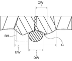
- FIG. 5 is an enlarged cross-sectional view showing a welded portion of the metal pipe of FIG. 7. It is a graph which shows the relationship between the residual width of the 2nd inclined surface in the electric sewn metal pipe, and the pressing load. It is explanatory drawing which shows the dimension of each part of a welded part.
- FIG. 1 is an explanatory diagram showing an electric sewing metal pipe manufacturing facility for carrying out the electric sewing metal pipe manufacturing method according to the first embodiment of the present invention.
- the electric sewing metal pipe manufacturing equipment of FIG. 1 is an equipment for manufacturing an electric sewing metal pipe 2 from a flat metal strip 1.
- the electrosewn metal pipe manufacturing equipment is provided with an edge crash equipment 3, a crushing equipment 4, a forming roll group 5, a welding equipment 6, an outer bead cutting machine 7, and a seam annealing equipment 8.
- the edge crash equipment 3 and the crushing equipment 4 are equipment for correcting the shape of the side edge of the metal band 1. These edge crash equipment 3 and crushing equipment 4 will be described later with reference to the drawings.
- the forming roll group 5 is composed of a plurality of forming rolls, and is arranged on the downstream side of the crushing facility 4 related to the transport direction 1a of the metal band 1.
- the metal strip 1 whose side end shape has been corrected by the edge crash facility 3 and the crushing facility 4 is gradually curved by the forming roll group 5 to form an open pipe 5a.
- the open pipe 5a is a tube body having a C-shaped cross section in which the side ends on both sides along the width direction of the metal band 1 are butted against each other and an opening is provided at the portion where the side ends are butted against each other.
- the welding equipment 6 is equipment arranged on the downstream side of the forming roll group 5 related to the transport direction 1a of the metal band 1, and has a heating coil 60 and a pair of squeeze roll equipment 61.
- the heating coil 60 is a coil through which a high frequency current is passed.
- the squeeze roll equipment 61 is equipment for restraining the outer circumference of the open pipe 5a, and the side ends of the metal strip 1 in the open pipe 5a melted by heating in the heating coil 60 are pressed against each other and joined (welded). .. That is, in the electric sewing metal pipe manufacturing equipment of the present embodiment, the electric sewing metal pipes are manufactured by abutting the side ends of the metal strip 1 and then welding the side ends by high frequency heating.
- the outer bead cutting machine 7 is arranged on the downstream side of the welding equipment 6 related to the transport direction 1a of the metal band 1, and cuts the outer bead of the metal pipe (the metal pipe immediately after the welding equipment 6) after the electric sewing welding. It is a device for welding.
- the outer bead cutting machine 7 includes a cutting tool for cutting the outer bead. In the electric sewing metal pipe manufacturing equipment of the present embodiment, the inner bead of the metal pipe after electric sewing welding is not cut.
- the seam annealing equipment 8 is arranged on the downstream side of the outer bead cutting machine 7 related to the transport direction 1a of the metal band 1, and is equipment for performing an annealing treatment (annealing treatment) on the welded portion of the metal pipe.
- annealing treatment annealing treatment
- the weld is heated so as to remove the internal strain of the weld.
- the electrosewn metal tube 2 of the present embodiment is a metal tube that has been annealed by the seam annealing equipment 8.
- a straightening facility for correcting the size and shape of the metal tube may be provided after the seam annealing facility 8.
- the metal pipe after the straightening in the straightening equipment corresponds to the electric sewing metal pipe 2.
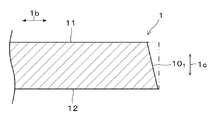
- FIG. 2 is a front view showing a main part of the edge crash facility 3 of FIG. 1
- FIG. 3 is a cross-sectional view showing an enlarged side end of the metal band 1 of FIG.
- the edge crush facility 3 is provided with a pair of edge crush rolls 30 for correcting the shape of the side end of the metal band 1.
- the edge crash rolls 30 are arranged apart from each other in the width direction 1b of the metal band 1.
- the width direction 1b is a direction orthogonal to the transport direction 1a.
- the metal strip 1 is passed between the edge crush rolls 30.
- the edge crush roll 30 is provided with an edge crush surface 30a that is inclined and extended with respect to the rotation axis of the edge crush roll 30.
- edge crush surface 30a is pressed against the side end of the metal band 1 and the first inclined surface 10 1 is pressed against the side end of the metal band 1 (see FIG. 3). Is formed.
- the metal band 1 is provided with an inner peripheral side surface 11 forming an inner peripheral surface of the electric sewing metal tube 2 and an outer peripheral side surface 12 forming an outer peripheral surface of the electric sewing metal tube 2.
- the first inclined surface 10 1 With located outside of the width direction 1b of the metal strip 1 at the outer peripheral side surface 12 side, located on the inner side of the width direction 1b in the inner peripheral surface 11 side, the metal strip It is inclined and extended with respect to 1c in the plate thickness direction of 1.
- First inclined surface 10 1 is preferably formed on the entire side end between the inner peripheral surface 11 and the outer peripheral surface 12.
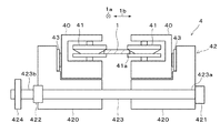
- FIG. 4 is a front view showing the crushing facility 4 of FIG. 1
- FIG. 5 is an enlarged front view showing the crushing roll of FIG. 4
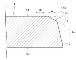
- FIG. 6 is the side of the metal band 1 of FIG. It is sectional drawing which shows the edge enlarged.
- the crushing facility 4 is provided with a pair of roll stands 40, a pair of crushing rolls 41, a crushing roll adjusting mechanism 42, and a crushing roll load meter 43.
- the pair of roll stands 40 are arranged apart from each other in the width direction 1b of the metal band 1 and rotatably support the crushing rolls 41, respectively.
- the metal strip 1 is passed between the crushing rolls 41.
- the crushing roll 41 is provided with a crushing surface 41a that extends so as to be inclined with respect to the rotation axis of the crushing roll 41.
- the inclination angle of the crushing surface 41a with respect to the rotation axis of the crushing roll 41 is the inclination angle of the edge crush surface 30a with respect to the rotation axis of the edge crush roll 30 (that is, the first inclined surface 10 1 with respect to the plate thickness direction 1c of the metal band 1). It is made larger than the tilt angle of.
- the edge of the inner peripheral side surface 11 of the metal band 1 before being passed between the crushing rolls 41 is on the inner surface side located on the inner surface side of the electrosewn metal tube 2.
- a corner portion 11a is provided.
- the second inclined surface 10 2 has a width W along the width direction 1b of the metal band 1, and extends so as to be inclined by an angle ⁇ with respect to the inner peripheral side surface 11 of the metal band 1.
- the crushing roll adjusting mechanism 42 is a mechanism for adjusting the pressing load of the crushing roll 41 against the inner surface side corner portion 11a by changing the separation distance of the pair of crushing rolls 41. ..
- the crushing roll adjusting mechanism 42 of the present embodiment has a pair of bases 420, first and second bearings 421 and 422, a ball screw 423 and a handle 424.
- the base 420 is connected to the roll stand 40 via a crushing roll load meter 43.
- the roll stand 40 and the crushing roll 41 can be integrally displaced with the base 420 via the crushing roll load meter 43.
- the first and second bearings 421 and 422 are attached to the base 420.
- the first bearing 421 rotatably supports the tip portion 423a of the ball screw 423.
- the second bearing 422 rotatably supports the base end portion 423b of the ball screw 423.
- the tip end portion 423a and the base end portion 423b are portions including one end and the other end of the ball screw 423 in the longitudinal direction.
- the ball screw 423 of the present embodiment is rotatably supported at both ends in the longitudinal direction.
- the handle 424 is a member that can be gripped by the operator, and is attached to the base end portion 423b of the ball screw 423.
- the base 420 is displaced along the width direction 1b of the metal band 1 in the direction toward and away from each other.
- the separation distance of the crushing roll 41 is changed. As the separation distance of the crushing roll 41 becomes narrower, the pressing load of the crushing roll 41 against the inner surface side corner portion 11a becomes larger.
- the separation distance of the crushing roll 41 can be adjusted by rotating the ball screw 423.
- the crushing roll adjusting mechanism 42 may have other aspects such as, for example, the roll stands 40 are individually displaced by an actuator to change the separation distance of the crushing rolls 41.
- the crushing roll load meter 43 is a sensor for measuring the pressing load of the crushing roll 41 against the inner surface side corner portion 11a.
- the crushing roll load meter 43 is arranged so that its measuring axis is along the width direction 1b of the metal band 1.
- the measured value of the crushing roll load meter 43 can be displayed on the display and recorded on the recording device.
- the crushing roll load meter 43 of the present embodiment is inserted between the roll stands 40 on both sides of the metal band 1 in the width direction 1b and the base 420, and both sides of the metal band 1 in the width direction 1b. Measure the pressing load with. However, since the base 420 of the present embodiment is connected by the ball screw 423, the pressing load of one crushing roll 41 related to the width direction 1b of the metal band 1 is applied to the width direction 1b of the metal band 1. It becomes a reaction force of the pressing load of the other crushing roll 41. Therefore, the crushing roll load meter 43 is inserted between the roll stand 40 on one side of the metal band 1 in the width direction 1b and the base 420, and is pushed by only one side of the metal band 1 in the width direction 1b.
- the applied load may be measured.
- the roll stand 40 on the side where the crushing roll load meter 43 is not inserted and the base 420 are connected by a member that replaces the crushing roll load meter 43, for example, a rod shaft.
- the crushing roll load meter measures the pressing load of the crushing rolls 41 on both sides in the width direction 1b of the metal strip 1.
- the metal band 1 used for manufacturing the electrosewn metal tube 2 may be cut out from a larger metal band, and burrs and sagging may occur at the side ends when the metal band 1 is cut out.
- burr side is the inner peripheral side surface 11 in order to stably form the first and second inclined surfaces 101 and 2 .
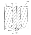
- FIG. 7 is a cross-sectional view of the metal pipe after electric sewing welding by the welding equipment 6 of FIG. 1, and FIG. 8 is an enlarged cross-sectional view of the welded portion of the metal pipe of FIG.
- the welded portion 100 of the metal pipe after electric stitch welding includes a joint portion 101 and a heat-affected zone 102.
- the joint portion 101 is a portion where the side ends of the molten metal band 1 are joined to each other.
- the heat-affected zone 102 is a portion affected by heating at the time of melting of the side end.
- the structure of the joint portion 101 and the heat-affected zone 102 is different from that of the non-heat-affected zone 103 due to the influence of heat.
- Discharge metal 101a protrudes from the joint 101 toward the inside of the metal pipe.
- the discharged metal 101a is a metal band 1 that is solidified by being extruded from the joint portion 101 when the side ends of the metal strip 1 are pressed against each other.
- the formation of the discharged metal 101a has a role of discharging the oxide (penetrator) contained in the molten metal from the joint portion 101.
- a surplus 102a is formed in the heat-affected zone 102.
- the surplus 102a is a portion where the metal softened in the heat-affected zone 102 is raised by the pressure when the side ends of the metal strip 1 are pressed against each other.
- the method for manufacturing the electrosewn metal tube of the present embodiment is Before abutting the side ends of the metal strip 1 in the welding equipment 6, a pair of crushing rolls 41 arranged on both sides of the metal strip 1 are pressed against the inner surface side corner portion 11a and second inclined to the inner surface side corner portion 11a.
- a step of adjusting the pressing load when the pair of crushing rolls 41 are pressed against the inner surface side corner portion 11a so as to form the remaining second inclined surface 10 2 on the inner surface side corner portion 11a is included. Since the second inclined surface 10 2 remains on the surplus 102a, the discharged metal 101a can be non-welded to the surplus 102a.
- the toughness of the discharged metal 101a is reduced due to the influence of heat. Therefore, when the electrosewn metal tube 2 is subjected to harsh processing such as bending at 90 °, the discharge metal 101a may be cracked. As described above, when the second inclined surface 10 2 remains on the surplus 102a of the metal pipe after electric sewing welding and the discharge metal 101a is not welded to the surplus 102a, the discharge metal 101a is cracked. Even so, it is possible to prevent the cracks from propagating to the base metal.
- the discharged metal 101a may be in contact with the surplus 102a as long as it is not welded to the surplus 102a. The presence or absence of welding of the discharged metal 101a to the surplus 102a can be confirmed by observing the cross section of the welded portion 100 in the metal pipe after electric stitch welding.
- the second inclined surface 10 2 remains on the surplus 102 a is affected by the width W (see FIG. 6) of the second inclined surface 10 2 .
- the width W of the second inclined surface 10 2 is larger, the amount of discharged metal 101 a is smaller, so that the second inclined surface 10 2 is likely to remain. More pressing load of crushing roll 41 to the inner surface side corner portion 11a is large, the second inclined surface 10 2 of the width W is increased. However, when the pressing load of the crushing roll 41 to the inner surface side corner portion 11a is too large, the width W of the second inclined surface 10 2 is also too large. If the width W is too large, the second inclined surface 10 2 bites into the base metal, and the plate thickness of the welded portion 100 becomes thin. Therefore, it is preferable that the pressing load of the crushing roll 41 against the inner surface side corner portion 11a is kept within a certain range.
- the second inclined surface 10 2 is formed according to the characteristics of the metal band 1 such as tensile strength and plate thickness.
- the width W changes. Therefore, the relationship between the pressing load of the crushing roll 41 and the width W of the second inclined surface 10 2 formed is grasped for each characteristic of the metal band 1, and the crushing roll corresponding to the characteristic of the metal band 1 is grasped.
- the appropriate second inclined surface 10 2 is used as the surplus 102a of the metal pipe after electrosew welding. It can be retained.
- the method for manufacturing the electrosewn metal tube of the present embodiment further includes a step of monitoring the pressing load when the pair of crushing rolls 41 are pressed against the inner surface side corner portion 11a.
- monitoring the pressing load it is possible to eliminate the portion where the abnormal load is generated and to continuously correct the pressing load. As a result, the quality can be stabilized and the product yield can be improved.
- the tip of the succeeding metal end may be joined to the tail end of the preceding metal band to continuously manufacture the electrosewn metal tube.
- the set value of the pressing load of the crushing roll 41 can be changed for each of the characteristics of these metal strips.
- the present inventors used a metal band 1 having a tensile strength of 750 MPa class, a plate thickness of 4.5 mm, and a plate width of 69.5 mm, and changed the pressing load of the crushing roll 41 to have a diameter of 24.
- the remaining width of the second inclined surface 10 2 - can be represented by (the second inclined surface 10 2 of the width after the welding width of the discharge metal 101a) / 2.
- the second inclined surface 10 2 is referred to as a crushing surface or C for the sake of clarity.
- the electrosewn metal tube 2 whose characteristics can be evaluated as being comprehensively good can be manufactured.
- the characteristics can be evaluated as good overall by setting the pressing load of the crushing roll 41 in the range of 19 kN or more and less than 32 kN. It is understood that tube 2 can be manufactured.
- the abnormal load generation portion can be eliminated and the pressing load can be continuously corrected. As a result, the quality can be stabilized and the product yield can be improved.
- the pair of crushing rolls 41 are pressed against the inner surface side corner portion 11a with a pressing load of 19 kN or more and less than 32 kN, so that the tensile strength of the metal band 1 is 1.
- the electro-sewn metal tube 2 having good characteristics can be manufactured when the value is 750 MPa class.
Landscapes
- Engineering & Computer Science (AREA)
- Mechanical Engineering (AREA)
Abstract
本発明に係る電縫金属管の製造設備は、金属帯1の両側に配置され、金属帯1の側端が突き合わされる前に金属帯の内面側角部に押し当てられて、内面側角部に傾斜面を形成するための一対のクラッシングロール41と、一対のクラッシングロール41の離間距離を変更して、内面側角部へのクラッシングロール41の押し当て荷重を調整するためのクラッシングロール調整機構42と、内面側角部へのクラッシングロール41の押し当て荷重を計測するためのクラッシングロール荷重計43とを備える。
Description
本発明は、金属帯の側端を突き合わせた後に側端を溶接して電縫金属管を製造する電縫金属管の製造設備及び方法に関する。
従来用いられていたこの種の電縫金属管の製造設備及び方法としては、例えば下記の特許文献1等に示されている構成を挙げることができる。すなわち、従来構成では、ペネトレータを溶接部から除くために、金属帯の側端にテーパ形状を付与した後に電縫溶接を行う。
上記のような従来構成のように溶接部からペネトレータを取り除いても、例えば90°曲げ等の過酷な加工を電縫溶接管に施した場合に電縫溶接管の溶接部にクラックが生じることがあった。
溶接部のクラックを詳細に調査したところ、以下のような新たな知見を得た。すなわち、溶接部から排出された排出メタルは熱の影響により靱性が低下しており、過酷な加工により排出メタルにクラックが生じやすい。クラックが生じた溶接部を観察したところ、排出メタルに生じたクラックが余盛を通して母材に伝播していた。
本発明は、上記のような課題を解決するためになされたものであり、その目的は、排出メタルにクラックが生じる場合であっても、母材までクラックが伝播することを回避できる電縫金属管の製造設備及び方法を提供することである。
本発明に係る電縫金属管の製造設備は、両側の側端を互いに突き合わせるように金属帯を湾曲させてオープンパイプを形成するとともに、オープンパイプを構成する金属帯の側端を高周波加熱により溶接して電縫金属管を製造するための電縫金属管の製造設備であって、側端には、電縫金属管の内面側に位置する内面側角部が設けられており、金属帯の両側に配置され、側端が突き合わされる前に内面側角部に押し当てられて、内面側角部に傾斜面を形成するための一対のクラッシングロールと、一対のクラッシングロールの離間距離を変更して、内面側角部へのクラッシングロールの押し当て荷重を調整するためのクラッシングロール調整機構と、内面側角部へのクラッシングロールの押し当て荷重を計測するためのクラッシングロール荷重計とを備える。
本発明に係る電縫金属管の製造方法は、両側の側端を互いに突き合わせるように金属帯を湾曲させてオープンパイプを形成するとともに、オープンパイプを構成する金属帯の側端を高周波加熱により溶接して電縫金属管を製造するための電縫金属管の製造方法であって、側端には、電縫金属管の内面側に位置する内面側角部が設けられており、側端を突き合わせる前に、金属帯の両側に配置された一対のクラッシングロールを内面側角部に押し当てて内面側角部に傾斜面を形成する工程と、一対のクラッシングロールを内面側角部に押し当てる前に、一対のクラッシングロールの離間距離を変更して、電縫溶接後の金属管の余盛に残存する傾斜面を内面側角部に形成するように、一対のクラッシングロールが内面側角部に押し当てられる際の押し当て荷重を調節する工程とを含む。
本発明の電縫金属管の製造設備及び方法によれば、一対のクラッシングロールにより内面側角部に傾斜面が形成されるので、電縫溶接後の金属管の余盛に傾斜面を残存させて、排出メタルを余盛と非溶着とすることができる。これにより、排出メタルにクラックが生じる場合であっても、母材までクラックが伝播することを回避できる。
以下、本発明を実施するための形態について、図面を参照して説明する。なお、本発明は実施の形態に限定されるものではなく、その要旨を逸脱しない範囲で構成要素を変形して具体化できる。また、実施の形態に示される全構成要素からいくつかの構成要素を削除してもよい。
図1は、本発明の実施の形態1による電縫金属管の製造方法を実施するための電縫金属管製造設備を示す説明図である。図1の電縫金属管製造設備は、平板状の金属帯1から電縫金属管2を製造するための設備である。この電縫金属管製造設備には、エッジクラッシュ設備3、クラッシング設備4、フォーミングロール群5、溶接設備6、外面ビード切削器7及びシームアニール設備8が設けられている。
エッジクラッシュ設備3及びクラッシング設備4は、金属帯1の側端の形状を矯正するための設備である。これらエッジクラッシュ設備3及びクラッシング設備4については、後に図面を用いて説明する。
フォーミングロール群5は、複数のフォーミングロールによって構成されるものであり、金属帯1の搬送方向1aに係るクラッシング設備4の下流側に配置されている。エッジクラッシュ設備3及びクラッシング設備4で側端の形状が矯正された金属帯1は、フォーミングロール群5で徐々に湾曲されてオープンパイプ5aとされる。オープンパイプ5aは、金属帯1の幅方向に沿う両側の側端を互い突き合わせたものであり、それら側端が突き合わされた部分に開口を有する断面C字状の管体である。
溶接設備6は、金属帯1の搬送方向1aに係るフォーミングロール群5の下流側に配置された設備であり、加熱コイル60及び一対のスクイズロール設備61を有している。加熱コイル60は、高周波電流が通されるコイルである。加熱コイル60の内側をオープンパイプ5aが通されるとき、オープンパイプ5aを構成する金属帯1の側端が加熱(高周波加熱)されて溶融される。スクイズロール設備61は、オープンパイプ5aの外周を拘束するための設備であり、加熱コイル60における加熱で溶融されたオープンパイプ5aにおける金属帯1の側端を互いに押し当てて接合する(溶接する)。すなわち、本実施の形態の電縫金属管製造設備では、金属帯1の側端を突き合わせた後に側端を高周波加熱により溶接して電縫金属管を製造する。
外面ビード切削器7は、金属帯1の搬送方向1aに係る溶接設備6の下流側に配置されており、電縫溶接後の金属管(溶接設備6の直後の金属管)の外面ビードを切削するための機器である。外面ビード切削器7は、外面ビードを切削するための刃物を含む。本実施の形態の電縫金属管製造設備では、電縫溶接後の金属管の内面ビードは切削されない。
シームアニール設備8は、金属帯1の搬送方向1aに係る外面ビード切削器7の下流側に配置されており、金属管の溶接部にアニール処理(焼きなまし処理)を施すための設備である。アニール処理では、溶接部の内部ひずみを除去するように溶接部が加熱される。
本実施の形態の電縫金属管2は、シームアニール設備8にてアニール処理を受けた後の金属管である。図示はしないが、金属管の大きさ及び形状を矯正する矯正設備がシームアニール設備8の後段に設けられていてもよい。矯正設備が設けられる場合、矯正設備における矯正後の金属管が電縫金属管2に相当する。
次に、図2は図1のエッジクラッシュ設備3の要部を示す正面図であり、図3は図2の金属帯1の側端を拡大して示す断面図である。図2に示すように、エッジクラッシュ設備3には、金属帯1の側端の形状を矯正するための一対のエッジクラッシュロール30が設けられている。エッジクラッシュロール30は、金属帯1の幅方向1bに互いに離間して配置されている。幅方向1bは、搬送方向1aに直交する方向である。金属帯1は、エッジクラッシュロール30の間を通される。
エッジクラッシュロール30には、エッジクラッシュロール30の回転軸に対して傾斜して延在されたエッジクラッシュ面30aが設けられている。金属帯1がエッジクラッシュロール30の間を通されるとき、エッジクラッシュ面30aが金属帯1の側端に押し当てられて金属帯1の側端に第1傾斜面101(図3参照)が形成される。
図3に示すように、金属帯1には、電縫金属管2の内周面を構成する内周側表面11と、電縫金属管2の外周面を構成する外周側表面12とが設けられている。第1傾斜面101は、外周側表面12側で金属帯1の幅方向1bに係る外側に位置するとともに、内周側表面11側で幅方向1bに係る内側に位置するように、金属帯1の板厚方向1cに対して傾斜して延在されている。このような第1傾斜面101が金属帯1の側端に形成されていることで、金属帯1が湾曲された際の内周面と外周面との周長差が補正されて、金属帯1の側端がより確実に突き合わせられる。第1傾斜面101は、内周側表面11と外周側表面12との間の全側端に形成されていることが好ましい。
次に、図4は図1のクラッシング設備4を示す正面図であり、図5は図4のクラッシングロールを拡大して示す正面図であり、図6は図5の金属帯1の側端を拡大して示す断面図である。図4に示すように、クラッシング設備4には、一対のロールスタンド40、一対のクラッシングロール41、クラッシングロール調整機構42及びクラッシングロール荷重計43が設けられている。
一対のロールスタンド40は、金属帯1の幅方向1bに互いに離間して配置されており、クラッシングロール41をそれぞれ回転自在に支持している。金属帯1は、クラッシングロール41の間を通される。
図5に特に表れているように、クラッシングロール41には、クラッシングロール41の回転軸に対して傾斜して延在されたクラッシング面41aが設けられている。クラッシングロール41の回転軸に対するクラッシング面41aの傾斜角度は、エッジクラッシュロール30の回転軸に対するエッジクラッシュ面30aの傾斜角度(すなわち、金属帯1の板厚方向1cに対する第1傾斜面101の傾斜角度)よりも大きくされている。
図6において二点鎖線で示すように、クラッシングロール41の間を通される前の金属帯1の内周側表面11の縁には、電縫金属管2の内面側に位置する内面側角部11aが設けられている。金属帯1がクラッシングロール41の間を通されるとき、内面側角部11aにクラッシング面41aが押し当てられて金属帯1の側端に第2傾斜面102(図6参照)が形成される。第2傾斜面102は、金属帯1の幅方向1bに沿う幅Wを有しており、金属帯1の内周側表面11に対して角度θだけ傾斜して延在されている。金属帯1の側端に第2傾斜面102が形成されることで、後に図8等を用いて説明するように電縫溶接後の金属管の余盛102aと排出メタル101aとを非溶着としやすくなる。
図4に戻り、クラッシングロール調整機構42は、一対のクラッシングロール41の離間距離を変更して、内面側角部11aへのクラッシングロール41の押し当て荷重を調整するための機構である。本実施の形態のクラッシングロール調整機構42は、一対の基台420、第1及び第2軸受421,422、ボールねじ423及びハンドル424を有している。
基台420は、クラッシングロール荷重計43を介してロールスタンド40に接続されている。ロールスタンド40及びクラッシングロール41は、クラッシングロール荷重計43を介して基台420と一体に変位可能とされている。
第1及び第2軸受421,422は、基台420に取り付けられている。第1軸受421は、ボールねじ423の先端部423aを回転自在に支持している。第2軸受422は、ボールねじ423の基端部423bを回転自在に支持している。先端部423a及び基端部423bは、ボールねじ423の長手方向に係る一端及び他端を含む部分である。本実施の形態のボールねじ423は、長手方向に係る両端部を回転自在に支持されている。
ハンドル424は、作業者が把持可能な部材であり、ボールねじ423の基端部423bに取り付けられている。ハンドル424が回転操作されてボールねじ423が回転されることで、基台420が金属帯1の幅方向1bに沿って互いに近づく方向及び離れる方向に変位される。基台420が変位されることで、クラッシングロール41の離間距離が変更される。クラッシングロール41の離間距離が狭くなるほど、内面側角部11aへのクラッシングロール41の押し当て荷重が大きくなる。
本実施の形態では、ボールねじ423の回転によりクラッシングロール41の離間距離が調整できるように説明している。しかしながら、クラッシングロール調整機構42は、例えばアクチュエータによりロールスタンド40を個々に変位させてクラッシングロール41の離間距離を変更する等の他の態様を有していてもよい。
クラッシングロール荷重計43は、内面側角部11aへのクラッシングロール41の押し当て荷重を計測するためのセンサである。クラッシングロール荷重計43は、その計測軸が金属帯1の幅方向1bに沿うように配置されている。クラッシングロール荷重計43の計測値は、表示器に表示できるとともに記録装置に記録できる。
本実施の形態のクラッシングロール荷重計43は、金属帯1の幅方向1bに係る両側のロールスタンド40と基台420との間に挿入されており、金属帯1の幅方向1bに係る両側で押し当て荷重を計測する。しかしながら、本実施の形態の基台420はボールねじ423により連結されているため、金属帯1の幅方向1bに係る一方のクラッシングロール41の押し当て荷重は、金属帯1の幅方向1bに係る他方のクラッシングロール41の押し当て荷重の反力となる。このため、クラッシングロール荷重計43は、金属帯1の幅方向1bに係る片側のロールスタンド40と基台420との間に挿入されて、金属帯1の幅方向1bに係る片側のみで押し当て荷重を計測してもよい。クラッシングロール荷重計43が挿入されていない側のロールスタンド40と基台420との間は、例えば棒軸等のクラッシングロール荷重計43の代わりとなる部材で接続される。各ロールスタンド40が個々に変位される態様では、クラッシングロール荷重計は、金属帯1の幅方向1bに係る両側のクラッシングロール41の押し当て荷重をそれぞれ計測することが好ましい。
なお、電縫金属管2の製造に用いる金属帯1はより大きな金属帯から切り出されることがあり、金属帯1の切り出し時に側端にバリ及びダレが生じることがある。側端にバリ及びダレが生じている場合、第1及び第2傾斜面101,2を安定的に形成するため、バリ側が内周側表面11とされることが好ましい。
次に、図7は図1の溶接設備6による電縫溶接後の金属管の断面図であり、図8は図7の金属管の溶接部を拡大して示す断面図である。図7及び図8に示すように、電縫溶接後の金属管の溶接部100には、接合部101と熱影響部102とが含まれている。接合部101は、溶融された金属帯1の側端が互いに接合されている部分である。熱影響部102は、側端の溶融時の加熱の影響を受けた部分である。接合部101及び熱影響部102は、熱の影響により非熱影響部103から組織が変わっている。
接合部101からは、金属管の内方に向けて排出メタル101aが突出されている。排出メタル101aは、金属帯1の側端が互いに押し当てられた際に溶融金属が接合部101から押し出されて固化したものである。この排出メタル101aの形成は、溶融金属に含まれる酸化物(ペネトレータ)を接合部101から排出するとの役割を有している。
熱影響部102には、余盛102aが形成されている。余盛102aは、金属帯1の側端を互いに押し当てる際に、その圧力により熱影響部102において軟化された金属が隆起した部分である。
本実施の形態の電縫金属管の製造方法は、
溶接設備6において金属帯1の側端を突き合わせる前に、金属帯1の両側に配置された一対のクラッシングロール41を内面側角部11aに押し当てて内面側角部11aに第2傾斜面102を形成する工程と、
一対のクラッシングロール41を内面側角部11aに押し当てる前に、一対のクラッシングロール41の離間距離を変更して、図8に示すように電縫溶接後の金属管の余盛102aに残存する第2傾斜面102を内面側角部11aに形成するように、一対のクラッシングロール41が内面側角部11aに押し当てられる際の押し当て荷重を調節する工程とを含む。
余盛102aに第2傾斜面102が残存することで、排出メタル101aを余盛102aと非溶着とすることができる。
溶接設備6において金属帯1の側端を突き合わせる前に、金属帯1の両側に配置された一対のクラッシングロール41を内面側角部11aに押し当てて内面側角部11aに第2傾斜面102を形成する工程と、
一対のクラッシングロール41を内面側角部11aに押し当てる前に、一対のクラッシングロール41の離間距離を変更して、図8に示すように電縫溶接後の金属管の余盛102aに残存する第2傾斜面102を内面側角部11aに形成するように、一対のクラッシングロール41が内面側角部11aに押し当てられる際の押し当て荷重を調節する工程とを含む。
余盛102aに第2傾斜面102が残存することで、排出メタル101aを余盛102aと非溶着とすることができる。
排出メタル101aは、熱の影響により靱性が低下している。このため、電縫金属管2に例えば90°曲げ等の過酷な加工を施した際に、排出メタル101aにクラックが生じることがある。上述のように、電縫溶接後の金属管の余盛102aに第2傾斜面102が残存し、排出メタル101aを余盛102aと非溶着とすることで、排出メタル101aにクラックが生じる場合であっても、母材までクラックが伝播することを回避できる。なお、排出メタル101aは、余盛102aに溶着されていなければ、余盛102aに接していても構わない。余盛102aへの排出メタル101aの溶着の有無は、電縫溶接後の金属管における溶接部100の断面を観察することで確認できる。
余盛102aに第2傾斜面102が残存するか否かには、第2傾斜面102の幅W(図6参照)が影響する。第2傾斜面102の幅Wが大きいほど、排出メタル101aが少ないので、第2傾斜面102が残存しやすい。内面側角部11aへのクラッシングロール41の押し当て荷重が大きいほど、第2傾斜面102の幅Wが大きくなる。しかしながら、内面側角部11aへのクラッシングロール41の押し当て荷重が大き過ぎると、第2傾斜面102の幅Wも大きくなり過ぎる。幅Wが大き過ぎると、第2傾斜面102が母材に食い込み、溶接部100の板厚が薄くなってしまう。このため、内面側角部11aへのクラッシングロール41の押し当て荷重は一定範囲に収めることが好ましい。
クラッシングロール41を金属帯1の側端に同じ押し当て荷重で押し当てても、例えば引張強さ及び板厚等の金属帯1の特性に応じて、形成される第2傾斜面102の幅Wが変わる。このため、クラッシングロール41の押し当て荷重と形成される第2傾斜面102の幅Wとの関係を金属帯1の特性毎に把握して、金属帯1の特性に応じたクラッシングロール41の押し当て荷重となるようにクラッシングロール調整機構42によりクラッシングロール41の離間距離を変更することで、適正な第2傾斜面102を電縫溶接後の金属管の余盛102aに残存させることができる。
また、本実施の形態の電縫金属管の製造方法は、一対のクラッシングロール41を内面側角部11aに押し当てる際の押し当て荷重を監視する工程をさらに含む。押し当て荷重を監視することにより、異常荷重の発生部を排除できるとともに、押し当て荷重を連続的に修正することができる。これにより、品質を安定させることができ、製品歩留を向上できる。
電縫金属管の製造方法においては、先行金属帯の尾端に後続金属端の先端を接合し、電縫金属管を連続的に製造することもある。これらの金属帯の特性毎に、クラッシングロール41の押し当て荷重の設定値を変更することができる。
次に、実施例を挙げる。本発明者らは、引張強さが750MPa級、板厚が4.5mm、板幅が69.5mmの金属帯1を用いて、クラッシングロール41の押し当て荷重を変更しながら、直径24.2mm、板厚4.5mmの電縫金属管2を製造した。そして、押し当て荷重ごとに、電縫金属管2における第2傾斜面102の残存幅を調べるとともに、(1)曲げ加工性の評価、(2)余盛102aに第2傾斜面102が残存するか否か、(3)排出メタル101aの安定性、(4)溶接部100の板厚確保及び(5)それらの総合評価を行った。その結果を下記の表1に示す。また、図9として、電縫金属管2における第2傾斜面102の残存幅と押し当て荷重(クラッシング荷重)との関係を示すグラフを挙げる。また、図10に、溶接部100の各部の寸法を示している。図10において、BHはビード高さを示し、EWは余盛幅を示し、DWは排出メタル幅を示し、Cはクラッシング面を示し、CWはクラッシング面の残存幅を示している。なお、第2傾斜面102の残存幅は、(溶接後の第2傾斜面102の幅-排出メタル101aの幅)/2で表すことができる。図9、図10及び表1では、内容を分かりやすくするために、第2傾斜面102をクラッシング面又はCと表記している。

(1)曲げ加工性の評価について
表1では、電縫金属管2に対して1.3D曲げ加工を行った際に溶接部100が破断せず、かつ内視鏡評価で母材に亀裂伝播が生じていない場合を〇で表している。一方、破断又は亀裂伝播が確認された場合を×で表している。1.3D曲げ加工では、電縫金属管2を長さ500mmに切り出した後、電縫金属管2の外径Dに1.3を乗じた曲げ半径にて、溶接部100を外側に向けるように電縫金属管2に回転引き曲げ加工を行った。
表1では、電縫金属管2に対して1.3D曲げ加工を行った際に溶接部100が破断せず、かつ内視鏡評価で母材に亀裂伝播が生じていない場合を〇で表している。一方、破断又は亀裂伝播が確認された場合を×で表している。1.3D曲げ加工では、電縫金属管2を長さ500mmに切り出した後、電縫金属管2の外径Dに1.3を乗じた曲げ半径にて、溶接部100を外側に向けるように電縫金属管2に回転引き曲げ加工を行った。
(2)余盛102aに第2傾斜面102が残存するか否かについて
表1では、余盛102aに第2傾斜面102が残存している場合を〇で表し、余盛102aに第2傾斜面102が残存していない場合を×で表している。
表1では、余盛102aに第2傾斜面102が残存している場合を〇で表し、余盛102aに第2傾斜面102が残存していない場合を×で表している。
(3)排出メタル101aの安定性について
表1では、排出メタル101aの高さ及び幅が長手方向に安定していた場合を〇で表し、排出メタル101aの高さ及び幅が長手方向に不安定であった場合を×で表している。より具体的には、高さが1.5mm以下の排出メタル101aが長手方向に延在している場合に、排出メタル101aの高さが安定していたと判断した。また、排出メタル101aが余盛102aに非溶着である状態が長手方向に続く場合に、排出メタル101aの幅が安定していたと判断した。
表1では、排出メタル101aの高さ及び幅が長手方向に安定していた場合を〇で表し、排出メタル101aの高さ及び幅が長手方向に不安定であった場合を×で表している。より具体的には、高さが1.5mm以下の排出メタル101aが長手方向に延在している場合に、排出メタル101aの高さが安定していたと判断した。また、排出メタル101aが余盛102aに非溶着である状態が長手方向に続く場合に、排出メタル101aの幅が安定していたと判断した。
(4)溶接部100の板厚確保について
表1では、素材金属板の板厚からの溶接部100の板厚変動が±0.06mm以内である場合を〇で表し、溶接部100の板厚変動が±0.06mmを超えていた場合を×で表している。
表1では、素材金属板の板厚からの溶接部100の板厚変動が±0.06mm以内である場合を〇で表し、溶接部100の板厚変動が±0.06mmを超えていた場合を×で表している。
(5)総合評価について
上述の(1)~(4)の評価がすべて〇であった場合を〇で表し、(1)~(4)の評価に×が含まれていた場合を×で表している。
上述の(1)~(4)の評価がすべて〇であった場合を〇で表し、(1)~(4)の評価に×が含まれていた場合を×で表している。
表1に示す結果から、クラッシングロール41の押し当て荷重を所定範囲に収めることで、特性を総合的に良好と評価できる電縫金属管2を製造できると理解される。特に、引張強さが750MPa級の金属帯1を使用するとき、クラッシングロール41の押し当て荷重を19kN以上かつ32kN未満の範囲とすることで、特性を総合的に良好と評価できる電縫金属管2を製造できると理解される。
このような電縫金属管の製造設備及び方法では、一対のクラッシングロール41により内面側角部11aに第2傾斜面102が形成されるので、電縫溶接後の金属管の余盛102aに第2傾斜面102を残存させて、排出メタル101aを余盛102aと非溶着とすることができる。これにより、排出メタル101aにクラックが生じる場合であっても、母材までクラックが伝播することを回避できる。
また、一対のクラッシングロール41を内面側角部11aに押し当てる際の押し当て荷重を監視するので、異常荷重の発生部を排除できるとともに、押し当て荷重を連続的に修正することができる。これにより、品質を安定させることができ、製品歩留を向上できる。
さらに、金属帯1の引張強さが750MPa級であるとき、19kN以上かつ32kN未満の押し当て荷重で一対のクラッシングロール41を内面側角部11aに押し当てるので、金属帯1の引張強さが750MPa級であるときに特性が良好な電縫金属管2を製造できる。
Claims (4)
- 両側の側端を互いに突き合わせるように金属帯を湾曲させてオープンパイプを形成するとともに、前記オープンパイプを構成する前記金属帯の前記側端を高周波加熱により溶接して電縫金属管を製造するための電縫金属管の製造設備であって、前記側端には、前記電縫金属管の内面側に位置する内面側角部が設けられており、
前記金属帯の両側に配置され、前記側端が突き合わされる前に前記内面側角部に押し当てられて、前記内面側角部に傾斜面を形成するための一対のクラッシングロールと、
前記一対のクラッシングロールの離間距離を変更して、前記内面側角部への前記クラッシングロールの押し当て荷重を調整するためのクラッシングロール調整機構と、
前記内面側角部への前記クラッシングロールの押し当て荷重を計測するためのクラッシングロール荷重計と
を備えている、電縫金属管の製造設備。 - 両側の側端を互いに突き合わせるように金属帯を湾曲させてオープンパイプを形成するとともに、前記オープンパイプを構成する前記金属帯の前記側端を高周波加熱により溶接して電縫金属管を製造するための電縫金属管の製造方法であって、前記側端には、前記電縫金属管の内面側に位置する内面側角部が設けられており、
前記側端を突き合わせる前に、前記金属帯の両側に配置された一対のクラッシングロールを前記内面側角部に押し当てて前記内面側角部に傾斜面を形成する工程と、
前記一対のクラッシングロールを前記内面側角部に押し当てる前に、前記一対のクラッシングロールの離間距離を変更して、電縫溶接後の金属管の余盛に残存する傾斜面を前記内面側角部に形成するように、前記一対のクラッシングロールが前記内面側角部に押し当てられる際の押し当て荷重を調節する工程と
を含む、電縫金属管の製造方法。 - 前記一対のクラッシングロールを前記内面側角部に押し当てる際の押し当て荷重を監視する工程をさらに含む、
請求項2記載の電縫金属管の製造方法。 - 前記金属帯の引張強さが750MPa級であるとき、19kN以上かつ32kN未満の押し当て荷重で前記一対のクラッシングロールを前記内面側角部に押し当てる、
請求項2又は請求項3に記載の電縫金属管の製造方法。
Priority Applications (1)
| Application Number | Priority Date | Filing Date | Title |
|---|---|---|---|
| PCT/JP2019/024140 WO2020255264A1 (ja) | 2019-06-18 | 2019-06-18 | 電縫金属管の製造設備及び方法 |
Applications Claiming Priority (1)
| Application Number | Priority Date | Filing Date | Title |
|---|---|---|---|
| PCT/JP2019/024140 WO2020255264A1 (ja) | 2019-06-18 | 2019-06-18 | 電縫金属管の製造設備及び方法 |
Publications (1)
| Publication Number | Publication Date |
|---|---|
| WO2020255264A1 true WO2020255264A1 (ja) | 2020-12-24 |
Family
ID=74037040
Family Applications (1)
| Application Number | Title | Priority Date | Filing Date |
|---|---|---|---|
| PCT/JP2019/024140 Ceased WO2020255264A1 (ja) | 2019-06-18 | 2019-06-18 | 電縫金属管の製造設備及び方法 |
Country Status (1)
| Country | Link |
|---|---|
| WO (1) | WO2020255264A1 (ja) |
Citations (5)
| Publication number | Priority date | Publication date | Assignee | Title |
|---|---|---|---|---|
| JPS5823289U (ja) * | 1981-08-04 | 1983-02-14 | 日本パイプ製造株式会社 | 帯鋼のエツジ成形装置 |
| JPH04300019A (ja) * | 1991-03-27 | 1992-10-23 | Kawasaki Steel Corp | 電縫管製造装置 |
| JP2001259733A (ja) * | 2000-03-16 | 2001-09-25 | Mitsubishi Shindoh Co Ltd | 電縫管の製造装置および製造方法 |
| JP2015147239A (ja) * | 2014-02-07 | 2015-08-20 | Jfeスチール株式会社 | 電縫鋼管の製造方法 |
| WO2018147389A1 (ja) * | 2017-02-13 | 2018-08-16 | 日新製鋼株式会社 | 電縫金属管の製造方法及びその電縫金属管 |
-
2019
- 2019-06-18 WO PCT/JP2019/024140 patent/WO2020255264A1/ja not_active Ceased
Patent Citations (5)
| Publication number | Priority date | Publication date | Assignee | Title |
|---|---|---|---|---|
| JPS5823289U (ja) * | 1981-08-04 | 1983-02-14 | 日本パイプ製造株式会社 | 帯鋼のエツジ成形装置 |
| JPH04300019A (ja) * | 1991-03-27 | 1992-10-23 | Kawasaki Steel Corp | 電縫管製造装置 |
| JP2001259733A (ja) * | 2000-03-16 | 2001-09-25 | Mitsubishi Shindoh Co Ltd | 電縫管の製造装置および製造方法 |
| JP2015147239A (ja) * | 2014-02-07 | 2015-08-20 | Jfeスチール株式会社 | 電縫鋼管の製造方法 |
| WO2018147389A1 (ja) * | 2017-02-13 | 2018-08-16 | 日新製鋼株式会社 | 電縫金属管の製造方法及びその電縫金属管 |
Similar Documents
| Publication | Publication Date | Title |
|---|---|---|
| TWI308088B (ja) | ||
| JP6987005B2 (ja) | 電縫金属管の製造設備及び方法 | |
| WO2020255264A1 (ja) | 電縫金属管の製造設備及び方法 | |
| US11504797B2 (en) | Method for manufacturing electroseamed metal tube | |
| JP5055938B2 (ja) | 溶接部特性の良好な電縫管の製造装置 | |
| TW202100258A (zh) | 電縫金屬管的製造設備以及電縫金屬管的製造方法 | |
| CN103764308A (zh) | 小径金属管的制造方法以及制造装置 | |
| EP2039441A1 (en) | Apparatus for manufacturing seam-welded pipe excelling in welded portion characteristic | |
| JP5055848B2 (ja) | 溶接部特性の良好な電縫管の製造方法 | |
| JP3327510B2 (ja) | 電縫管の製造方法 | |
| JP4613777B2 (ja) | 溶接部特性の良好な電縫管の安定製造方法 | |
| JP6127709B2 (ja) | プレス切断用電縫管及びその製造方法 | |
| JP4720479B2 (ja) | 溶接部特性の良好な電縫管の高能率製造方法 | |
| JP4236918B2 (ja) | めっき鋼管の製造方法 | |
| JP2008110399A (ja) | 溶接部特性の良好な電縫管製造方法 | |
| JP2007330983A (ja) | 溶接部特性の良好な電縫管の製造方法 | |
| JP2024114517A (ja) | 溶接装置及び電縫管の製造方法 | |
| JP2025070386A (ja) | 板巻き加工品の製造方法 | |
| JP4682779B2 (ja) | 溶接部特性の良好な電縫管製造方法 | |
| JP2025009235A (ja) | 電縫管の製造方法及び溶接装置 | |
| JP2009119484A (ja) | 溶接部特性に優れた電縫管の製造方法 | |
| JP2008302379A (ja) | 溶接部特性に優れた電縫管製造方法 | |
| JPH10235428A (ja) | レーザ溶接管の製造方法およびその製造装置 | |
| JP2008080390A (ja) | 溶接部特性の良好な電縫管の製造方法 | |
| JP2008307571A (ja) | 溶接部特性に優れた電縫管製造方法 |
Legal Events
| Date | Code | Title | Description |
|---|---|---|---|
| 121 | Ep: the epo has been informed by wipo that ep was designated in this application |
Ref document number: 19933806 Country of ref document: EP Kind code of ref document: A1 |
|
| NENP | Non-entry into the national phase |
Ref country code: DE |
|
| 122 | Ep: pct application non-entry in european phase |
Ref document number: 19933806 Country of ref document: EP Kind code of ref document: A1 |
|
| NENP | Non-entry into the national phase |
Ref country code: JP |