WO2020250697A1 - 通知システムおよび通知方法 - Google Patents
通知システムおよび通知方法 Download PDFInfo
- Publication number
- WO2020250697A1 WO2020250697A1 PCT/JP2020/021076 JP2020021076W WO2020250697A1 WO 2020250697 A1 WO2020250697 A1 WO 2020250697A1 JP 2020021076 W JP2020021076 W JP 2020021076W WO 2020250697 A1 WO2020250697 A1 WO 2020250697A1
- Authority
- WO
- WIPO (PCT)
- Prior art keywords
- abnormality
- notification
- subject
- information
- unit
- Prior art date
- Legal status (The legal status is an assumption and is not a legal conclusion. Google has not performed a legal analysis and makes no representation as to the accuracy of the status listed.)
- Ceased
Links
Images















Classifications
-
- G—PHYSICS
- G16—INFORMATION AND COMMUNICATION TECHNOLOGY [ICT] SPECIALLY ADAPTED FOR SPECIFIC APPLICATION FIELDS
- G16H—HEALTHCARE INFORMATICS, i.e. INFORMATION AND COMMUNICATION TECHNOLOGY [ICT] SPECIALLY ADAPTED FOR THE HANDLING OR PROCESSING OF MEDICAL OR HEALTHCARE DATA
- G16H50/00—ICT specially adapted for medical diagnosis, medical simulation or medical data mining; ICT specially adapted for detecting, monitoring or modelling epidemics or pandemics
- G16H50/30—ICT specially adapted for medical diagnosis, medical simulation or medical data mining; ICT specially adapted for detecting, monitoring or modelling epidemics or pandemics for calculating health indices; for individual health risk assessment
-
- A—HUMAN NECESSITIES
- A61—MEDICAL OR VETERINARY SCIENCE; HYGIENE
- A61B—DIAGNOSIS; SURGERY; IDENTIFICATION
- A61B5/00—Measuring for diagnostic purposes; Identification of persons
- A61B5/0002—Remote monitoring of patients using telemetry, e.g. transmission of vital signals via a communication network
- A61B5/0015—Remote monitoring of patients using telemetry, e.g. transmission of vital signals via a communication network characterised by features of the telemetry system
- A61B5/0022—Monitoring a patient using a global network, e.g. telephone networks, internet
-
- A—HUMAN NECESSITIES
- A61—MEDICAL OR VETERINARY SCIENCE; HYGIENE
- A61B—DIAGNOSIS; SURGERY; IDENTIFICATION
- A61B5/00—Measuring for diagnostic purposes; Identification of persons
- A61B5/24—Detecting, measuring or recording bioelectric or biomagnetic signals of the body or parts thereof
- A61B5/316—Modalities, i.e. specific diagnostic methods
- A61B5/318—Heart-related electrical modalities, e.g. electrocardiography [ECG]
- A61B5/332—Portable devices specially adapted therefor
-
- A—HUMAN NECESSITIES
- A61—MEDICAL OR VETERINARY SCIENCE; HYGIENE
- A61B—DIAGNOSIS; SURGERY; IDENTIFICATION
- A61B5/00—Measuring for diagnostic purposes; Identification of persons
- A61B5/24—Detecting, measuring or recording bioelectric or biomagnetic signals of the body or parts thereof
- A61B5/316—Modalities, i.e. specific diagnostic methods
- A61B5/318—Heart-related electrical modalities, e.g. electrocardiography [ECG]
- A61B5/346—Analysis of electrocardiograms
- A61B5/349—Detecting specific parameters of the electrocardiograph cycle
- A61B5/352—Detecting R peaks, e.g. for synchronising diagnostic apparatus; Estimating R-R interval
-
- A—HUMAN NECESSITIES
- A61—MEDICAL OR VETERINARY SCIENCE; HYGIENE
- A61B—DIAGNOSIS; SURGERY; IDENTIFICATION
- A61B5/00—Measuring for diagnostic purposes; Identification of persons
- A61B5/24—Detecting, measuring or recording bioelectric or biomagnetic signals of the body or parts thereof
- A61B5/316—Modalities, i.e. specific diagnostic methods
- A61B5/318—Heart-related electrical modalities, e.g. electrocardiography [ECG]
- A61B5/346—Analysis of electrocardiograms
- A61B5/349—Detecting specific parameters of the electrocardiograph cycle
- A61B5/361—Detecting fibrillation
-
- A—HUMAN NECESSITIES
- A61—MEDICAL OR VETERINARY SCIENCE; HYGIENE
- A61B—DIAGNOSIS; SURGERY; IDENTIFICATION
- A61B5/00—Measuring for diagnostic purposes; Identification of persons
- A61B5/24—Detecting, measuring or recording bioelectric or biomagnetic signals of the body or parts thereof
- A61B5/316—Modalities, i.e. specific diagnostic methods
- A61B5/318—Heart-related electrical modalities, e.g. electrocardiography [ECG]
- A61B5/346—Analysis of electrocardiograms
- A61B5/349—Detecting specific parameters of the electrocardiograph cycle
- A61B5/364—Detecting abnormal ECG interval, e.g. extrasystoles, ectopic heartbeats
-
- A—HUMAN NECESSITIES
- A61—MEDICAL OR VETERINARY SCIENCE; HYGIENE
- A61B—DIAGNOSIS; SURGERY; IDENTIFICATION
- A61B5/00—Measuring for diagnostic purposes; Identification of persons
- A61B5/24—Detecting, measuring or recording bioelectric or biomagnetic signals of the body or parts thereof
- A61B5/316—Modalities, i.e. specific diagnostic methods
- A61B5/318—Heart-related electrical modalities, e.g. electrocardiography [ECG]
- A61B5/346—Analysis of electrocardiograms
- A61B5/349—Detecting specific parameters of the electrocardiograph cycle
- A61B5/366—Detecting abnormal QRS complex, e.g. widening
-
- A—HUMAN NECESSITIES
- A61—MEDICAL OR VETERINARY SCIENCE; HYGIENE
- A61B—DIAGNOSIS; SURGERY; IDENTIFICATION
- A61B5/00—Measuring for diagnostic purposes; Identification of persons
- A61B5/68—Arrangements of detecting, measuring or recording means, e.g. sensors, in relation to patient
- A61B5/6801—Arrangements of detecting, measuring or recording means, e.g. sensors, in relation to patient specially adapted to be attached to or worn on the body surface
- A61B5/6802—Sensor mounted on worn items
- A61B5/6804—Garments; Clothes
-
- A—HUMAN NECESSITIES
- A61—MEDICAL OR VETERINARY SCIENCE; HYGIENE
- A61B—DIAGNOSIS; SURGERY; IDENTIFICATION
- A61B5/00—Measuring for diagnostic purposes; Identification of persons
- A61B5/72—Signal processing specially adapted for physiological signals or for diagnostic purposes
- A61B5/7235—Details of waveform analysis
-
- A—HUMAN NECESSITIES
- A61—MEDICAL OR VETERINARY SCIENCE; HYGIENE
- A61B—DIAGNOSIS; SURGERY; IDENTIFICATION
- A61B5/00—Measuring for diagnostic purposes; Identification of persons
- A61B5/72—Signal processing specially adapted for physiological signals or for diagnostic purposes
- A61B5/7271—Specific aspects of physiological measurement analysis
- A61B5/7282—Event detection, e.g. detecting unique waveforms indicative of a medical condition
-
- A—HUMAN NECESSITIES
- A61—MEDICAL OR VETERINARY SCIENCE; HYGIENE
- A61B—DIAGNOSIS; SURGERY; IDENTIFICATION
- A61B5/00—Measuring for diagnostic purposes; Identification of persons
- A61B5/74—Details of notification to user or communication with user or patient; User input means
- A61B5/746—Alarms related to a physiological condition, e.g. details of setting alarm thresholds or avoiding false alarms
-
- G—PHYSICS
- G16—INFORMATION AND COMMUNICATION TECHNOLOGY [ICT] SPECIALLY ADAPTED FOR SPECIFIC APPLICATION FIELDS
- G16H—HEALTHCARE INFORMATICS, i.e. INFORMATION AND COMMUNICATION TECHNOLOGY [ICT] SPECIALLY ADAPTED FOR THE HANDLING OR PROCESSING OF MEDICAL OR HEALTHCARE DATA
- G16H40/00—ICT specially adapted for the management or administration of healthcare resources or facilities; ICT specially adapted for the management or operation of medical equipment or devices
- G16H40/20—ICT specially adapted for the management or administration of healthcare resources or facilities; ICT specially adapted for the management or operation of medical equipment or devices for the management or administration of healthcare resources or facilities, e.g. managing hospital staff or surgery rooms
-
- G—PHYSICS
- G16—INFORMATION AND COMMUNICATION TECHNOLOGY [ICT] SPECIALLY ADAPTED FOR SPECIFIC APPLICATION FIELDS
- G16H—HEALTHCARE INFORMATICS, i.e. INFORMATION AND COMMUNICATION TECHNOLOGY [ICT] SPECIALLY ADAPTED FOR THE HANDLING OR PROCESSING OF MEDICAL OR HEALTHCARE DATA
- G16H40/00—ICT specially adapted for the management or administration of healthcare resources or facilities; ICT specially adapted for the management or operation of medical equipment or devices
- G16H40/60—ICT specially adapted for the management or administration of healthcare resources or facilities; ICT specially adapted for the management or operation of medical equipment or devices for the operation of medical equipment or devices
- G16H40/67—ICT specially adapted for the management or administration of healthcare resources or facilities; ICT specially adapted for the management or operation of medical equipment or devices for the operation of medical equipment or devices for remote operation
-
- A—HUMAN NECESSITIES
- A61—MEDICAL OR VETERINARY SCIENCE; HYGIENE
- A61B—DIAGNOSIS; SURGERY; IDENTIFICATION
- A61B5/00—Measuring for diagnostic purposes; Identification of persons
- A61B5/02—Detecting, measuring or recording for evaluating the cardiovascular system, e.g. pulse, heart rate, blood pressure or blood flow
- A61B5/024—Measuring pulse rate or heart rate
- A61B5/02438—Measuring pulse rate or heart rate with portable devices, e.g. worn by the patient
-
- A—HUMAN NECESSITIES
- A61—MEDICAL OR VETERINARY SCIENCE; HYGIENE
- A61B—DIAGNOSIS; SURGERY; IDENTIFICATION
- A61B5/00—Measuring for diagnostic purposes; Identification of persons
- A61B5/103—Measuring devices for testing the shape, pattern, colour, size or movement of the body or parts thereof, for diagnostic purposes
- A61B5/11—Measuring movement of the entire body or parts thereof, e.g. head or hand tremor or mobility of a limb
- A61B5/1116—Determining posture transitions
-
- A—HUMAN NECESSITIES
- A61—MEDICAL OR VETERINARY SCIENCE; HYGIENE
- A61B—DIAGNOSIS; SURGERY; IDENTIFICATION
- A61B5/00—Measuring for diagnostic purposes; Identification of persons
- A61B5/103—Measuring devices for testing the shape, pattern, colour, size or movement of the body or parts thereof, for diagnostic purposes
- A61B5/11—Measuring movement of the entire body or parts thereof, e.g. head or hand tremor or mobility of a limb
- A61B5/112—Gait analysis
-
- A—HUMAN NECESSITIES
- A61—MEDICAL OR VETERINARY SCIENCE; HYGIENE
- A61B—DIAGNOSIS; SURGERY; IDENTIFICATION
- A61B5/00—Measuring for diagnostic purposes; Identification of persons
- A61B5/24—Detecting, measuring or recording bioelectric or biomagnetic signals of the body or parts thereof
- A61B5/316—Modalities, i.e. specific diagnostic methods
- A61B5/318—Heart-related electrical modalities, e.g. electrocardiography [ECG]
- A61B5/346—Analysis of electrocardiograms
- A61B5/349—Detecting specific parameters of the electrocardiograph cycle
- A61B5/353—Detecting P-waves
-
- A—HUMAN NECESSITIES
- A61—MEDICAL OR VETERINARY SCIENCE; HYGIENE
- A61B—DIAGNOSIS; SURGERY; IDENTIFICATION
- A61B5/00—Measuring for diagnostic purposes; Identification of persons
- A61B5/48—Other medical applications
- A61B5/4806—Sleep evaluation
- A61B5/4809—Sleep detection, i.e. determining whether a subject is asleep or not
-
- A—HUMAN NECESSITIES
- A61—MEDICAL OR VETERINARY SCIENCE; HYGIENE
- A61B—DIAGNOSIS; SURGERY; IDENTIFICATION
- A61B5/00—Measuring for diagnostic purposes; Identification of persons
- A61B5/68—Arrangements of detecting, measuring or recording means, e.g. sensors, in relation to patient
- A61B5/6801—Arrangements of detecting, measuring or recording means, e.g. sensors, in relation to patient specially adapted to be attached to or worn on the body surface
- A61B5/6802—Sensor mounted on worn items
- A61B5/6804—Garments; Clothes
- A61B5/6805—Vests, e.g. shirts or gowns
-
- G—PHYSICS
- G16—INFORMATION AND COMMUNICATION TECHNOLOGY [ICT] SPECIALLY ADAPTED FOR SPECIFIC APPLICATION FIELDS
- G16H—HEALTHCARE INFORMATICS, i.e. INFORMATION AND COMMUNICATION TECHNOLOGY [ICT] SPECIALLY ADAPTED FOR THE HANDLING OR PROCESSING OF MEDICAL OR HEALTHCARE DATA
- G16H10/00—ICT specially adapted for the handling or processing of patient-related medical or healthcare data
- G16H10/60—ICT specially adapted for the handling or processing of patient-related medical or healthcare data for patient-specific data, e.g. for electronic patient records
Definitions
- the present invention relates to a notification system and a notification method for acquiring biological information of a subject using a wearable device and notifying the outside of an abnormality in the biological information.
- electrocardiographs There are multiple types and uses of electrocardiographs, but long-term electrocardiography is particularly effective for detecting sudden electrocardiographic abnormalities such as paroxysmal atrial fibrillation.
- electrocardiographs and electrodes have been developed that allow a subject to measure an electrocardiogram while living a normal life (see Patent Documents 1-3). With such an electrocardiograph, long-term electrocardiographic measurement becomes possible, and countermeasures against a sudden life crisis are being actively discussed.
- the present invention has been made to solve the above problems, and an object of the present invention is to provide a notification system and a notification method capable of reducing the possibility that a medical institution cannot respond to an abnormal occurrence of a subject.
- the notification system of the present invention determines whether or not there is an abnormality in the biological information of the subject and the biological information acquisition unit configured to acquire the biological information of the subject, and when it is determined that there is an abnormality.
- An abnormality determination unit configured to determine the degree of abnormality, and a memory configured to store information of a notification destination when an abnormality occurs in the biological information of the subject in advance for each degree of abnormality. It is configured to refer to the unit and the storage unit when an abnormality occurs in the biological information of the subject, and acquire information of a notification destination corresponding to the degree of abnormality determined by the abnormality determination unit.
- a notification unit and a notification unit configured to transmit information on the determination result of the abnormality determination unit, including the degree of abnormality, to the notification destination device indicated by the information acquired by the notification destination determination unit. It is characterized by having.
- the biometric information acquisition unit, the abnormality determination unit, the storage unit, the notification destination determination unit, and the notification unit are wearable devices worn by the subject. It is characterized in that it is provided.
- the biological information acquisition unit is provided on the wearable device worn by the subject, and the abnormality determination unit, the storage unit, the notification destination determination unit, and the notification are provided.
- the unit is provided in a notification device on a network, and the wearable device further includes a biometric information transmission unit configured to transmit the biometric information of the subject to the notification device. It is characterized by further including a biometric information receiving unit configured to receive the biometric information of the subject transmitted from the wearable device.
- the biometric information acquisition unit, the storage unit, the notification destination determination unit, and the notification unit are provided on the wearable device worn by the subject, and the abnormality is described.
- the determination unit is provided in a notification device on the network, and the wearable device includes a biometric information transmission unit configured to transmit the biometric information of the subject to the notification device, and the abnormality degree.
- the notification device further includes a determination result receiving unit configured to receive the determination result information of the abnormality determination unit from the notification device, and the notification device receives the biometric information of the subject transmitted from the wearable device. It is characterized by further including a biological information receiving unit configured as described above, and a determination result transmitting unit configured to transmit the determination result information of the abnormality determination unit including the abnormality degree to the wearable device. Is what you do.
- the biometric information transmitting unit is characterized in that the biometric information of the subject is transmitted to the notification device when the subject has permission to transmit. Is to be.
- the notification device provides a device of a predetermined judge or a website on which the judge can browse the biometric information of the subject transmitted from the wearable device.
- the abnormality determination unit further includes a determination determination result notification unit configured to transmit to the server device, and a determination determination result receiving unit configured to receive information on the determination result by the determination.
- the notification device is given to a subject wearing the wearable device when the biometric information receiving unit receives information transmitted from the wearable device. It is characterized by further including a reward calculation unit configured to calculate a reward and a reward information transmission unit configured to transmit the reward calculated by the reward calculation unit to an external device. ..
- the notification method of the present invention includes a first step of acquiring the biological information of the subject, a second step of determining whether or not there is an abnormality in the biological information of the subject, and the subject.
- the fourth step of acquiring the information of the notification destination corresponding to the abnormality degree determined in the third step and the information obtained by the second and third steps are referred to the storage unit stored in advance in the above.
- the fifth step of transmitting the information acquired in the fourth step to the notification destination device is included.
- the degree of abnormality is determined when it is determined that there is an abnormality, a notification destination corresponding to the degree of abnormality is selected, and the degree of abnormality is selected. Since the information of the judgment result of the abnormality judgment unit including the above is transmitted to the notification destination device, it is possible to smoothly take appropriate measures for the subject, and the medical institution can respond to the occurrence of the abnormality of the subject. It is possible to reduce the possibility of not being able to respond.
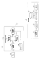
- FIG. 1 is a diagram illustrating an outline of a notification system according to a first embodiment of the present invention.
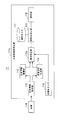
- FIG. 2 is a block diagram showing a configuration of a wearable device of the notification system according to the first embodiment of the present invention.
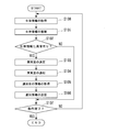
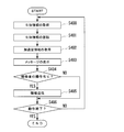
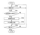
- FIG. 3 is a flowchart illustrating the operation of the wearable device of the notification system according to the first embodiment of the present invention.
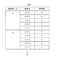
- FIG. 4 is a diagram showing an example of information registered in the notification destination database of the notification system according to the first embodiment of the present invention.
- FIG. 5 is a block diagram showing a configuration of a wearable device of the notification system according to the second embodiment of the present invention.
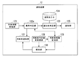
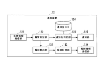
- FIG. 6 is a block diagram showing a configuration of a wearable device and a notification device of the notification system according to the third embodiment of the present invention.
- FIG. 7 is a flowchart illustrating the operation of the wearable device of the notification system according to the third embodiment of the present invention.
- FIG. 8 is a flowchart illustrating the operation of the notification device of the notification system according to the third embodiment of the present invention.
- FIG. 9 is a diagram showing an example of information registered in the notification destination database of the notification system according to the third embodiment of the present invention.
- FIG. 10 is a block diagram showing a configuration of a wearable device of the notification system according to the fourth embodiment of the present invention.
- FIG. 11 is a flowchart illustrating the operation of the wearable device of the notification system according to the fourth embodiment of the present invention.
- FIG. 12 is a diagram showing an example of information registered in the notification destination database of the notification system according to the sixth embodiment of the present invention.
- FIG. 13 is a block diagram showing a configuration of a notification device of the notification system according to the seventh embodiment of the present invention.
- FIG. 14 is a block diagram showing a configuration of a notification device of the notification system according to the eighth embodiment of the present invention.
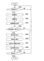
- FIG. 15 is a flowchart illustrating the operation of the notification device of the notification system according to the eighth embodiment of the present invention.
- FIG. 16 is a diagram showing an example of the judge information stored in the judge information storage unit of the notification device of the notification system according to the eighth embodiment of the present invention.
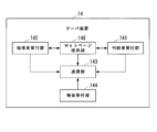
- FIG. 17 is a block diagram showing a configuration of a server device of a notification system according to a ninth embodiment of the present invention.
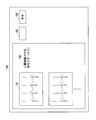
- FIG. 18 is a diagram showing an example of a Web page browsed by a determiner in the ninth embodiment of the present invention.
- FIG. 19 is a diagram showing an example of a Web page browsed by a subject in a ninth embodiment of the present invention.
- FIG. 20 is a block diagram showing a configuration of a wearable device and a notification device of the notification system according to the twelfth embodiment of the present invention.
- FIG. 21 is a flowchart illustrating the operation of the wearable device of the notification system according to the twelfth embodiment of the present invention.
- FIG. 22 is a flowchart illustrating the operation of the notification device of the notification system according to the twelfth embodiment of the present invention.
- FIG. 20 is a block diagram showing a configuration of a wearable device and a notification device of the notification system according to the twelfth embodiment of the present invention.
- FIG. 21 is a flowchart illustrating the operation of the wearable device of the notification system according to the t
- FIG. 23 is a block diagram showing a configuration of a notification device of the notification system according to the thirteenth embodiment of the present invention.
- FIG. 24 is a flowchart illustrating the operation of the notification device of the notification system according to the thirteenth embodiment of the present invention.
- FIG. 25 is a flowchart illustrating the abnormality degree determination process of the abnormality determination unit of the notification system according to the 14th embodiment of the present invention.
- FIG. 26 is a diagram showing an example of the correspondence between the symptom of the subject and the degree of abnormality.
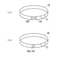
- FIG. 27 is a diagram showing an example of a band used when a subject wears a wearable device in the fifteenth embodiment of the present invention.
- FIG. 28 is a block diagram showing a configuration example of a computer that realizes a wearable device and a notification device of the notification system according to the first to fifteenth embodiments of the present invention.
- FIG. 1 is a diagram illustrating an outline of a notification system according to a first embodiment of the present invention.
- a wearable device 11 is attached to the body of the subject 100.
- FIG. 1 an example of the shirt-type wearable device 11 is described, but it goes without saying that the present invention is not limited to the shirt-type wearable device.
- the wearable device 11 has a wireless communication function or a wired communication function, and has a function of transmitting biometric information of the subject 100.
- electrocardiographic data is assumed as biometric information, but pulse data, acceleration data, respiration data, body temperature data, myoelectric data, and the like may be added.
- the notification device 12 receives the biological information of the subject from the wearable device 11, determines whether or not the biological information of the subject has an abnormality, and determines the degree of abnormality when the determination is made. It has a function of changing the determination result and the notification destination device 13 of the abnormality degree according to the abnormality degree.
- the notification device 12 may be provided on the network, and the wearable device 11 and the notification device 12 may be connected via the network, or the notification device 12 may be incorporated in the wearable device 11.
- the wearable device 11 and the notification device 12 it is not necessary to separately install the notification device 12, and the notification system can be easily constructed.
- the notification destination device 13 includes a device operated by a security company contracted by the subject or a relative of the subject, a device such as a smartphone owned by the relative of the subject, a smartphone owned by the subject himself, or the like. There are devices such as.
- the notification destination device 13 does not include a device of a medical institution.
- the reason why the medical institution is not the notification destination is that if the system directly notifies the medical institution of the condition of the subject, medical approval as a device related to medical practice is essential, so until the service of the notification system starts. This is because various procedures become complicated.
- FIG. 2 is a block diagram showing the configuration of the wearable device 11
- FIG. 3 is a flowchart illustrating the operation of the wearable device 11.
- the function of the notification device 12 is incorporated in the wearable device 11 will be described.
- the wearable device 11 includes an electrode 110 and a biological information acquisition device 111.
- the biological information acquisition device 111 includes a biological information acquisition unit 112 that acquires biological information of a subject, a biological information storage unit 113 that stores biological information, and a standard waveform generation unit 114 that generates a standard waveform of biological information.
- Abnormality determination unit 115 that determines whether or not there is an abnormality in the biological information of the subject and determines the degree of abnormality when it is determined that there is an abnormality, and when an abnormality occurs in the biological information of the subject, an abnormality occurs.
- the notification destination determination unit 116 that acquires the information of the notification destination corresponding to the abnormality degree determined by the determination unit 115 and the information of the notification destination when an abnormality occurs in the biological information of the subject are stored in advance for each abnormality degree.
- the information of the determination result of the abnormality determination unit 115 including the abnormality degree and the notification destination database (hereinafter referred to as the notification destination DB) 117 as the storage unit is directed to the notification destination device indicated by the information acquired by the notification destination determination unit 116. It is provided with a notification unit 118 for transmitting information.
- the biological information acquisition unit 112 of the wearable device 11 acquires the biological information (electrocardiographic waveform) of the subject via the electrode 110 attached to the subject (step S100 in FIG. 3). Since the electrode 110 has a well-known configuration in the wearable device 11, detailed description thereof will be omitted.
- the biological information received by the biological information acquisition unit 112 is stored in the biological information storage unit 113 of the wearable device 11 (step S101 in FIG. 3).
- the memory constituting the biological information storage unit 113 may be an external memory that can be attached to and detached from the biological information acquisition device 111, or may be a built-in memory.
- the standard waveform generation unit 114 of the wearable device 11 has a function of generating a standard waveform of an electrocardiographic waveform for each subject.
- a standard waveform for each individual is generated by superimposing a plurality of waveforms by a well-known method.
- a plurality of general electrocardiographic waveform patterns may be prepared, and those close to the normal electrocardiographic waveform of the subject may be selected and set in advance.
- the abnormality determination unit 115 of the wearable device 11 compares the electrocardiographic waveform indicated by the biological information of the subject stored in the biological information storage unit 113 with the standard waveform generated by the standard waveform generation unit 114, and compares the standard waveform generated by the standard waveform generation unit 114 with the subject. It is determined whether or not there is an abnormality in the biological information of (FIG. 3, step S102).
- abnormalities such as sinus bradycardia and sinus tachycardia can be detected from the P wave interval (PP interval) of the electrocardiographic waveform, or the electrocardiographic waveform. Since the R wave interval (RR interval) is irregular and the f wave is observed, there is a method of detecting an abnormality such as a risk of atrial fibrillation. Since such an abnormality determination method based on an electrocardiographic waveform is a well-known method, detailed description thereof will be omitted. Further, the abnormality may be determined only from the biological information of the subject, or the abnormality may be determined by comparing the biological information with the standard waveform as described above.
- the abnormality determination unit 115 determines that there is an abnormality in the biological information of the subject (YES in step S102), determines the degree of abnormality in the biological information (step S103 in FIG. 3), and notifies the abnormality degree flag indicating the degree of abnormality. It is transmitted to the first determination unit 116 (step S104 in FIG. 3).
- the degree of abnormality may be any number of stages, but is determined in five stages such as 5, 4, 3, 2, 1.
- a normal threshold value indicating a guideline for a normal value is set in advance.
- the abnormality determination unit 115 determines that the determination item of the biological information is normal if it is within the normal range defined by the normal threshold value. If the determination item of the biological information is outside the normal range defined by the normal threshold value, the abnormality determination unit 115 determines that the abnormality is present.
- the abnormality determination unit 115 may estimate the symptom of the subject (for example, atrial fibrillation, extra systole, angina, ventricular fibrillation, myocardial infarction, etc.) from the determination item in which the abnormality has occurred. ..
- a plurality of abnormality degree judgment threshold values for determining the degree of abnormality are set for each of the judgment items according to the amount of deviation of the judgment item of the biological information from the normal threshold value (for example, four in the case of five-step evaluation).
- Abnormality judgment threshold The abnormality determination unit 115 determines the degree of abnormality according to the amount of deviation of the determination item from the normal threshold value by comparing the amount of deviation of the determination item from the normal threshold value with a plurality of abnormality degree determination threshold values. Can be done.
- a plurality of abnormality determination threshold values for determining the abnormality degree are set according to the amount of deviation of the biological information from the standard waveform.
- the abnormality determination unit 115 can determine the degree of abnormality according to the amount of deviation of the biological information from the standard waveform by comparing the amount of deviation of the biological information from the standard waveform with a plurality of abnormality degree determination threshold values.
- the notification destination DB 117 of the wearable device 11 information on the notification destination (address of the notification destination device 13) when an abnormality occurs in the biological information of the subject is registered in advance for each degree of abnormality.
- FIG. 4 shows an example of the information registered in the notification destination DB 117.
- the degree of abnormality and the information of the notification destination are registered in association with each other.
- the notification destination determination unit 116 of the wearable device 11 When the notification destination determination unit 116 of the wearable device 11 receives the abnormality degree flag from the abnormality determination unit 115, it refers to the notification destination DB 117 and provides the notification destination information corresponding to the abnormality degree indicated by the abnormality degree flag to the notification destination DB 117. Obtained from (FIG. 3, step S105).
- the information of the notification destination DB 117 may be registered by the subject himself / herself, may be registered by a relative of the subject, may be registered by a doctor of a medical institution, or may be registered by the subject or the subject.
- the person in charge of the security company contracted by the relatives of the person may register, or the staff of the elderly home or nursing care facility where the subject resides may register.
- a method of registering information for example, there are a method of registering using a PC (Personal Computer) and a method of registering via a network. In the present invention, any registration method may be used.
- the notification unit 118 of the wearable device 11 generates notification information including the determination result of the abnormality determination unit 115, and transmits this notification information to the notification destination device 13 indicated by the information acquired by the notification destination determination unit 116 ( FIG. 3 step S106).
- the notification information includes the determination result of the abnormality determination unit 115 (information that there is an abnormality in the biological information, symptom information estimated from the determination item in which the abnormality has occurred, and the degree of abnormality).
- the wearable device 11 performs the processes of steps S100 to S106 at regular intervals until, for example, the subject instructs the end of the operation (YES in step S107 of FIG. 3).
- comments regarding urgency may be added to the notification information.
- a comment regarding urgency may be registered in advance in the notification destination DB 117 for each degree of abnormality so that the notification destination determination unit 116 can acquire the comment together with the information of the notification destination.
- the notification destination device 13 when an abnormality occurs in the biological information of the subject, the notification destination device 13 is selected according to the degree of the abnormality, and the selected notification destination device 13 is notified of the abnormality. Since the notification is provided, it is possible to smoothly perform a response suitable for the subject, and it is possible to reduce the possibility that the medical institution cannot respond to the occurrence of an abnormality in the subject.
- the relatives of the subject who possesses the notification destination device 13 are notified of the occurrence of an abnormality, they can take measures such as taking the subject to a medical institution or calling an ambulance.
- a notification destination device 13 operated by a security company contracted by the subject may be prepared. This enables the security company to provide detailed services to the subjects who have paid the contract fee.
- a special notification destination device 13 (notification destination device 13 operated by a medical institution, or a medical institution) is given to a subject who is determined to have a high degree of urgency (high degree of abnormality), regardless of whether or not there is a cost.
- the notification destination device 13) related to the above may be prepared in advance. As a result, it is possible to give priority to a subject who has a life-threatening risk.
- the notification destination device 13 may be a shared data box that can be viewed by medical institutions.
- the shared data box is a data box in which data can be viewed only by the medical institution by registering with the medical institution, although the data is not directly notified to the medical institution.
- FIG. 5 is a block diagram showing the configuration of the wearable device 11 of this embodiment.
- the wearable device 11 of this embodiment includes an electrode 110 and a biological information acquisition device 111a.
- the biological information acquisition device 111a includes a biological information acquisition unit 112, a biological information storage unit 113, a standard waveform generation unit 114, an abnormality determination unit 115a, a notification destination determination unit 116, a notification destination DB 117, and a notification unit 118.
- the acceleration sensor 119 is provided.
- the abnormality determination unit 115a uses the information of the acceleration sensor 119 together with the biological information of the subject stored in the biological information storage unit 113 to determine whether or not there is an abnormality in the biological information of the subject. Judgment (step S102 in FIG. 3).
- the acceleration sensor 119 can estimate the posture and behavior of the subject, the posture and behavior of the subject such as the subject is awake, the subject is sleeping, and the subject is walking. It is possible to make a judgment by combining the information of the above and the biological information.
- the above-mentioned normal threshold value is determined for each judgment item (for example, PP interval, RR interval, heart rate, QRS width from Q wave to S wave, height of P wave, etc.) and for the subject. It is preset for each posture and action.
- the abnormality determination unit 115a estimates the posture and behavior of the subject based on the acceleration detected by the acceleration sensor 119, and the determination items of the biological information are defined by the normal threshold value corresponding to the posture and behavior of the subject. If it is out of the normal range, it is judged to be abnormal. In this way, for example, when the RR interval is short (heart rate is high), it is determined that the heart rate is rising due to the exercise of the subject, or it is abnormal that the heart rate is rising at rest. It is possible to determine the state. Other configurations are as described in the first embodiment.
- FIG. 6 is a block diagram showing the configuration of the wearable device 11 and the notification device 12 of this embodiment.
- the wearable device 11 of this embodiment includes an electrode 110 and a biological information acquisition device 111b.
- the biological information acquisition device 111b includes a biological information acquisition unit 112, a biological information storage unit 113, a standard waveform generation unit 114, an acceleration sensor 119, and a biological information transmission unit 120.
- the notification device 12 includes a biological information receiving unit 121, an abnormality determination unit 122, a notification destination determination unit 123, a notification destination DB 124, and a notification unit 125.
- FIG. 7 is a flowchart explaining the operation of the wearable device 11 of this embodiment
- FIG. 8 is a flowchart explaining the operation of the notification device 12 of this embodiment.
- the processing of steps S200 and S201 of FIG. 7 is the same as the processing of steps S100 and S101 of FIG.
- the biological information transmission unit 120 of the wearable device 11 acquires the acceleration information detected by the acceleration sensor 119 (step S202 of FIG. 7).
- the biological information transmission unit 120 is generated by the subject ID (identification information) unique to the subject, the biological information of the subject stored in the biological information storage unit 113, and the standard waveform generation unit 114.
- Information on the standard waveform and information on the acceleration detected by the acceleration sensor 119 are transmitted to the notification device 12 (step S203 in FIG. 7).
- the wearable device 11 performs the processes of steps S200 to S203 at regular intervals until, for example, the subject instructs the end of the operation (YES in step S204 of FIG. 7).
- the biological information receiving unit 121 of the notification device 12 receives the information transmitted from the wearable device 11 (step S300 in FIG. 8). Similar to the abnormality determination unit 115a, the abnormality determination unit 122 of the notification device 12 has an abnormality in the subject's biological information based on the subject's biological information and acceleration information transmitted from the wearable device 11. Whether or not it is determined (FIG. 8 step S301).
- the abnormality determination unit 122 determines the degree of abnormality in the biological information when it is determined that there is an abnormality in the biological information of the subject (YES in step S301) (step 8). S302), the abnormality degree flag indicating the abnormality degree is transmitted to the notification destination determination unit 123 (step S303 in FIG. 8).
- the abnormality determination unit 122 may estimate the symptom of the subject from the determination item in which the abnormality has occurred, similarly to the abnormality determination units 115 and 115a.
- FIG. 9 shows an example of the information registered in the notification destination DB 124.
- the subject ID, the degree of abnormality, and the information of the notification destination are registered in association with each other.
- the notification destination determination unit 123 of the notification device 12 receives the abnormality degree flag from the abnormality determination unit 122, the notification destination DB 124 refers to the notification destination DB 124, and the abnormality indicated by the subject ID and the abnormality degree flag transmitted from the wearable device 11 Information on the notification destination corresponding to the degree is acquired from the notification destination DB 124 (step S304 in FIG. 8).
- the notification unit 125 of the notification device 12 Similar to the notification unit 118, the notification unit 125 of the notification device 12 generates notification information and transmits this notification information to the notification destination device 13 indicated by the information acquired by the notification destination determination unit 123 (FIG. 8). Step S305).
- the notification device 12 performs the processes of steps S300 to S305 at regular intervals until, for example, the administrator of the notification device 12 instructs the end of the operation (YES in step S306 of FIG. 8). In this way, in this embodiment, the abnormality determination and the notification to the notification destination device 13 can be performed by the notification device 12 on the network.
- FIG. 10 is a block diagram showing the configuration of the wearable device 11 of this embodiment.
- the wearable device 11 of this embodiment includes an electrode 110 and a biological information acquisition device 111c.
- the biological information acquisition device 111c includes a biological information acquisition unit 112, a biological information storage unit 113, a standard waveform generation unit 114, an acceleration sensor 119, a biological information transmission unit 120c, a display control unit 150, and a display unit 151.
- the operation unit 152 is provided.
- FIG. 11 is a flowchart illustrating the operation of the wearable device 11 of this embodiment.
- the processing of steps S400 to S402 of FIG. 11 is the same as the processing of steps S200 to S202 of FIG.
- the display control unit 150 of the wearable device 11 of the present embodiment sends a message to the display unit 151 asking the subject whether or not the information can be transmitted at the timing when the biological information transmission unit 120c can transmit information to the notification device 12. It is displayed (step S403 in FIG. 11).
- the display control unit 150 causes the display unit 151 to display a message such as "Do you want to transmit information?".
- the subject wishes to transmit information to the notification device 12, he / she operates the operation unit 152 (for example, pressing a button).
- the subject is operated by the biometric information transmission unit 120c of the wearable device 11 (YES in step S404 of FIG. 11)
- the information of the standard waveform generated by the standard waveform generation unit 114 and the information of the acceleration detected by the acceleration sensor 119 are transmitted to the notification device 12 (step S405 of FIG. 11).
- the biological information for the past several seconds, the standard waveform information, and the acceleration information may be transmitted to the notification device 12.
- the configuration and operation of the notification device 12 are as described in the third embodiment.
- Electrocardiographic abnormalities often have subjective symptoms in the subject itself.
- the information is transmitted to the notification device 12, so that the notification device 12 makes a timely diagnosis of the biological information of the subject with subjective symptoms. It has the effect of being able to.
- the wearable device 11 includes the acceleration sensor 119 in the third and fourth embodiments, the wearable device 11 may not have the acceleration sensor 119.
- the abnormality determination unit 122 of the notification device 12 performs the processing of steps S301 and S302 in the same manner as the abnormality determination unit 115 of the first embodiment.
- the amount of data transmitted from the wearable device 11 can be reduced, the power consumption of the wearable device 11 can be reduced, and the battery of the wearable device 11 can be reduced.
- the life of the device can be extended.
- the waveform generation unit 114 is unnecessary.
- the IP (Internet Protocol) address of the wearable device 11 and the ID of the SIM (Subscriber Identity Module) card for communication of the wearable device 11 are used. It may be an ID for identifying the examiner.
- FIG. 12 shows an example of the information registered in the notification destination DB 124 of the notification device 12 of this embodiment.
- the IP address or SIM card ID of the wearable device 11 the subject ID, the degree of abnormality, and the information of the notification destination are registered in association with each other.
- the biometric information transmission units 120 and 120c of the wearable device 11 are generated by the IP address or SIM card ID of the wearable device 11, the biometric information of the subject stored in the biometric information storage unit 113, and the standard waveform generation unit 114.
- the information of the standard waveform and the information of the acceleration detected by the acceleration sensor 119 are transmitted to the notification device 12 (step S203 in FIG. 7 and step S405 in FIG. 11).
- the notification destination determination unit 123 of the notification device 12 receives the abnormality degree flag from the abnormality determination unit 122, the notification destination DB 124 is referred to, and the IP address or SIM card ID and the abnormality degree flag transmitted from the wearable device 11 are displayed. Information on the notification destination corresponding to the indicated abnormality degree is acquired from the notification destination DB 124 (step S304 in FIG. 8).
- Other configurations are as described in the third to fifth embodiments.
- the wearable device 11 since the wearable device 11 is not equipped with the subject ID that can identify the subject, security can be improved.
- FIG. 13 is a block diagram showing the configuration of the notification device 12 of this embodiment.
- the notification device 12 of this embodiment includes a biological information receiving unit 121, an abnormality determination unit 122d, a notification destination determination unit 123, a notification destination DB 124, a notification unit 125, and another person database (hereinafter, another person DB) 126. And have.
- the other person DB126 stores the electrocardiographic waveform of a person who has been determined to be abnormal in the past and its degree of abnormality, or the value of the determination item of the biological information of the person who has been determined to be abnormal in the past and the degree of abnormality.
- the abnormality determination unit 122d of the notification device 12 is based on the biological information (or biological information and acceleration information) of the subject transmitted from the wearable device 11. It is determined whether or not there is an abnormality in the biological information (step S301 in FIG. 8).
- the abnormality determination unit 122d determines that there is an abnormality in the biological information of the subject (YES in step S301)
- the abnormality determination unit 122d determines the degree of abnormality in the biological information (step S302 in FIG. 8).
- the abnormality determination unit 122d uses the information of the other person registered in advance in the other person DB 126.
- the abnormality determination unit 122d determines the degree of abnormality according to the amount of deviation of the electrocardiographic waveform of the subject with respect to the electrocardiographic waveform of the other person registered in the other person DB126. At this time, the abnormality determination unit 122d compares the electrocardiographic waveform of the subject with the electrocardiographic waveform of the other person, and if the electrocardiographic waveform of the other person and the electrocardiographic waveform of the subject substantially match.
- the degree of abnormality of the subject is set to the same value as the degree of abnormality of the other person to be compared, and if the electrocardiographic waveform of the subject deviates to the normal side with respect to the electrocardiographic waveform of the other person, the subject If the degree of abnormality of the examiner is set to a value lower than the degree of abnormality of the other person to be compared, and the electrocardiographic waveform of the subject deviates further to the abnormal degree with respect to the electrocardiographic waveform of the other person, the subject is subject to The degree of abnormality of the examiner is set to a value higher than the degree of abnormality of the other person to be compared.
- the cross-correlation function between the electrocardiographic waveform of the subject and the electrocardiographic waveform of the other person to be compared may be used to determine the amount of deviation.
- the abnormality determination unit 122d determines the degree of abnormality according to the amount of deviation of the value of the determination item of the subject with respect to the value of the determination item of the other person registered in the other person DB 126.
- the abnormality determination unit 122d sets the abnormality degree of the subject to the same value as the abnormality degree of the other person to be compared. , If the value of the judgment item of the subject deviates to the normal value with respect to the value of the judgment item of the other person, the abnormality degree of the subject is lower than the abnormality degree of the other person to be compared. If the value of the judgment item of the subject deviates further from the value of the judgment item of the other person, the degree of abnormality of the subject is set to be higher than the degree of abnormality of the other person to be compared. Set to a high value.
- FIG. 14 is a block diagram showing the configuration of the notification device 12 of this embodiment.
- the notification device 12 of this embodiment includes a biological information receiving unit 121, an abnormality determination unit 122e, a notification destination determination unit 123, a notification destination DB 124, a notification unit 125, a determination person notification unit 127, and a determination person determination result. It includes a receiving unit 128, a determining person information storage unit 129, and a search unit 130.
- FIG. 15 is a flowchart illustrating the operation of the notification device 12 of this embodiment.
- the biometric information receiving unit 121 receives the information transmitted from the wearable device 11 (step S500 in FIG. 15)
- the determining person notification unit 127 of the notification device 12 transmits the received information to a predetermined external device of the determining person. (FIG. 15, step S501).
- the judge looks at the information transmitted from the notification device 12, determines whether or not there is an abnormality in the biological information of the subject, and if it is determined that there is an abnormality, determines the degree of abnormality.
- a doctor of a medical institution that has a contract in advance can be considered.
- the judge operates the device of the judge such as a PC, or inputs the information on the Web page described later, and determines the judgment result (information on the presence or absence of abnormality in the biological information and the presumed symptom).
- the comment and the above are transmitted to the notification device 12.
- the judge determination result receiving unit 128 of the notification device 12 sends the information received from the judge's device such as a PC or the server device that provides the Web page described later to the judge information storage unit 129 together with the biological information of the subject.
- the abnormality determination unit 122e of the notification device 12 determines whether or not there is an abnormality in the biological information of the subject, as in the first to sixth embodiments (step S503 of FIG. 15), and the biological information of the subject. When it is determined that there is an abnormality in the biological information, the degree of abnormality in the biological information is determined (FIG. 15, step S504). However, if there is a difference between the determination of the abnormality determination unit 122e and the determination result of the determination person, the abnormality determination unit 122e gives priority to the determination result of the determination person.
- steps S505 to S508 of FIG. 15 is the same as the processing of steps S303 to S306 of FIG.
- the other configurations are as described in the third to sixth embodiments.
- the abnormality determination method a method of arranging the judgment of the judge via the network is used.
- the notification system determines whether or not the biological information of the subject is abnormal, and the determination result by an expert can be added to this determination.
- the information may be transmitted to the device of the judge at the predetermined address, or the judge notification unit may be sent to a specific server device operated by the judge or a third party. 127 may transmit the information.
- the abnormality determination unit 122e determines the abnormality degree based on the comment of the judge when determining the abnormality degree (step S504). Specifically, the abnormality determination unit 122e determines the degree of abnormality based on the symptoms included in the comment (atrial fibrillation, extra systole, angina, ventricular fibrillation, myocardial infarction, etc.). If there are comments from multiple judges, the comment of the judge with the highest evaluation may be adopted based on the evaluation of the judges, or multiple judges may be selected according to the evaluation of the judges. The comment may be weighted to determine the degree of anomaly. The evaluation method of the judge will be described later.
- the seventh embodiment and the eighth embodiment may be combined so that the access right to the other DB 126 is given only to the highly evaluated judge. Since the biological information stored in the other person's DB126 has high medical value, it can be motivated by the judge to judge the biological information of the subject.
- FIG. 16 is a diagram showing an example of the judge information stored in the judge information storage unit 129.
- the judge information storage unit 129 the judge ID unique to the judge and the address of the judge's device or the URL (Uniform Resource Locator) of the website are registered in advance as the judge information I1 in association with each other. There is.
- the judge notification unit 127 of the notification device 12 transmits the information to the judgment device, or sends the information to the server device operated by the judgment or a third party.
- the judge information storage unit 129 as the judge information I2, the date and time information that the judge determines whether or not there is an abnormality in the biological information of the subject, the judge ID, the subject ID, and the subject are examined.
- the biological information of the person, the judgment result of the judgment person, the comment of the judgment person, and the evaluation information of the subject with respect to the judgment person are registered in association with each other.
- the subject's evaluation information for the judge becomes the status of the judge and can be used as important weighting information when determining the degree of abnormality.
- the evaluation information of the subject with respect to the judge can also be used as the evaluation of the judge (doctor) or the medical institution.
- FIG. 17 is a block diagram showing the configuration of the server device of this embodiment.
- the server device 14 includes a Web page providing unit 140 that provides a Web page of the judge's site on the network, a judging reception unit 141, a subject reception unit 142, a transmission unit 143, and a search reception unit 144. It has.
- the server device 14 is operated by a judge or a third party other than the judge.
- FIG. 18 is a diagram showing an example of a Web page 180 viewed by a judge in this embodiment.
- the Web page providing unit 140 of the server device 14 publishes the Web page of the judge's site on the network. Access is restricted so that only the judge and the subject can browse the web page of the judge. In addition, the subject can only view information about himself / herself among the information that can be viewed by the judge.
- the Web page providing unit 140 has an authentication function for identifying a judge and a subject. Since such an authentication function is a well-known technique, detailed description thereof will be omitted.
- 181 of the Web page 180 of FIG. 18 is an electrocardiographic waveform of a subject.
- 182 is a comment added by the judge to the electrocardiographic waveform of the subject.
- the judge reception unit 141 of the server device 14 displays the comment input by the judge on the Web page 180.
- the transmission unit 143 of the server device 14 includes the judge ID, the ID of the subject to be judged, and the judgment result (information on the presence or absence of abnormality in the biological information) input by the judge via the judge reception unit 141.
- the presumed symptom) and the comment of the judge are transmitted to the notification device 12.
- the judgment information I2 is stored in the judgment information storage unit 129 of the notification device 12 as described above.
- the subject ID is included in the information transmitted from the notification device 12.
- the judge inputs a comment, but the judge may select from the comment options prepared in advance. If the judge selects a comment from the options, the fluctuation of the comment is reduced and the data management becomes easier. In addition, the time and effort required for the judge to input can be reduced.
- FIG. 19 is a diagram showing an example of a Web page 190 that the subject browses on a PC, a smartphone, or the like in this embodiment.
- the Web page providing unit 140 of the server device 14 provides the Web page 190 so that only the information about the subject himself / herself can be viewed among the information that can be viewed by the judge.
- the Web page providing unit 140 has an authentication function for the subject in order to identify the subject.
- the Web page providing unit 140 displays the evaluation button 184 operated by the subject on the Web page 190.
- the evaluation button 184 in which the subject evaluates the judge positively and the evaluation button 184 in which the subject evaluates the judge negatively are displayed as “No”. Button 184 is displayed.
- the subject reception unit 142 of the server device 14 receives the evaluation information for the judge entered by the subject on the Web page 190. Then, the transmission unit 143 of the server device 14 includes the ID of the judge to be evaluated, the ID of the subject who has input the evaluation information, and the evaluation information input by the subject via the subject reception unit 142. Is transmitted to the notification device 12. In this way, by transmitting the evaluation information of the subject to the judgment device to the notification device 12, the evaluation information is stored in the judgment person information storage unit 129 of the notification device 12 as described above.
- FIG. 19 an example of two-stage evaluation of good / bad is shown, but it may be configured to evaluate in a plurality of stages. This enables a detailed evaluation of the judge. Further, in the example of FIG. 19, only the comments of one judge are displayed, but the comments of a plurality of judges are displayed so that the subject can evaluate each of the plurality of judges. You can.
- the eleventh embodiment of the present invention will be described. Also in this embodiment, the configuration of the server device 14 is as described in the tenth embodiment. As shown in FIG. 18, a keyword input field 185 and a search button 186 are displayed on the Web page 180 viewed by the judge.
- the judge operates his / her own PC or the like, inputs a keyword in the keyword input field 185 on the Web page 180, and clicks the search button 186.
- the search reception unit 144 of the server device 14 receives the keyword input by the judge.
- the transmission unit 143 of the server device 14 transmits the keyword input by the determiner via the search reception unit 144 to the notification device 12.
- the search unit 130 of the notification device 12 receives the keyword from the server device 14, the search unit 130 refers to the judgment information storage unit 129 and extracts the judgment information I2 including the keyword. Then, the judge notification unit 127 of the notification device 12 transmits the judgment information I2 extracted by the search unit 130 to the server device 14.
- the Web page providing unit 140 of the server device 14 displays the judge information I2 transmitted from the notification device 12 on the Web page 180 viewed by the judge.
- the judge can browse the biometric information of another subject whose symptom similar to that of the subject is described in the comment column, and is stored in the judge information storage unit 129. It is possible to utilize the vast amount of information available as medical data.
- FIG. 20 is a block diagram showing the configuration of the wearable device 11 and the notification device 12 of this embodiment.
- the wearable device 11 of this embodiment includes an electrode 110 and a biological information acquisition device 111f.
- the biological information acquisition device 111f includes a biological information acquisition unit 112, a biological information storage unit 113, a standard waveform generation unit 114, an acceleration sensor 119, a biological information transmission unit 120, a determination result receiving unit 153, and a notification destination determination.
- a unit 154, a notification destination DB 155, and a notification unit 156 are provided.
- the notification device 12 includes a biological information receiving unit 121, an abnormality determination unit 122, and a determination result transmission unit 131.
- FIG. 21 is a flowchart explaining the operation of the wearable device 11 of this embodiment
- FIG. 22 is a flowchart explaining the operation of the notification device 12 of this embodiment.
- the processing of steps S600 to S603 of the wearable device 11 shown in FIG. 21 is the same as the processing of steps S200 to S203 of FIG.
- steps S700 to S702 of the notification device 12 shown in FIG. 22 is the same as the processing of steps S300 to S302 of FIG.
- the determination result transmission unit 131 of the notification device 12 wears information on the determination result of the abnormality determination unit 122 (information that there is an abnormality in the biological information, symptom information estimated from the determination item in which the abnormality has occurred, and the degree of abnormality). It is transmitted to the device 11 (step S703 in FIG. 22).
- the notification device 12 performs the processes of steps S700 to S703 at regular intervals until, for example, the administrator of the notification device 12 instructs the end of the operation (YES in step S704 of FIG. 22).
- the notification destination determination unit 154 of the wearable device 11 when the determination result receiving unit 153 receives the determination result from the notification device 12 (YES in step S604 of FIG. 21), the determination result indicates that there is an abnormality (FIG. Yes) in 21 step S605), the notification destination DB 155 is referred to, and the information of the notification destination corresponding to the abnormality degree indicated by the abnormality degree flag is acquired from the notification destination DB 155 (FIG. 21 step S606).
- the configuration of the notification destination DB 155 is the same as that of the notification destination DB 117.
- the notification unit 156 of the wearable device 11 generates notification information including the determination result received from the notification device 12, and transmits this notification information to the notification destination device 13 indicated by the information acquired by the notification destination determination unit 154. (FIG. 21 step S607).
- the wearable device 11 performs the processes of steps S600 to S607 at regular intervals until, for example, the subject instructs the end of the operation (YES in step S608 of FIG. 21).
- the abnormality determination of the biological information is performed by the notification device 12 on the network as in the third embodiment, but the selection of the notification destination device 13 and the notification destination device are performed as in the first and second embodiments.
- the notification to 13 is performed on the wearable device 11.
- the information of the other person DB 126 can be utilized by transmitting the biological information of the subject to the notification device 12 on the network. Further, in the eighth embodiment, by transmitting the biological information of the subject to the notification device 12 on the network, it is possible to expect the judge to receive the detailed judgment result.
- FIG. 23 is a block diagram showing the configuration of the notification device 12 of this embodiment.
- the notification device 12 of this embodiment includes a biological information receiving unit 121, an abnormality determination unit 122, a notification destination determination unit 123, a notification destination DB 124, a notification unit 125, a reward calculation unit 132, and a reward storage unit 133.
- the reward information transmitting unit 134 is provided.
- FIG. 24 is a flowchart illustrating the operation of the notification device 12 of this embodiment.
- the reward calculation unit 132 of the notification device 12 gives a reward to the subject wearing the wearable device 11 when the biological information receiving unit 121 receives the information transmitted from the wearable device 11 (step S800 in FIG. 24). (Points and money) are calculated (FIG. 24, step S801).
- the reward calculation unit 132 may identify the subject based on the subject ID transmitted from the wearable device 11, for example, and calculate the reward according to the number of transmissions of the biometric information of the subject. It may be calculated by another calculation method.
- the value of the reward calculated by the reward calculation unit 132 is stored in the reward storage unit 133 in association with the subject ID (step S802 in FIG. 24).
- the reward information transmission unit 134 of the notification device 12 transmits the subject ID and the reward value stored in the reward storage unit 133 to a predetermined external device (step 803 in FIG. 24).
- a predetermined external device for example, there is a server device of an insurance company contracted by the subject.
- steps S804 to S809 of FIG. 24 is the same as the processing of steps S301 to S306 of FIG.
- the insurance company reduces the insurance premium by the amount of this remuneration. It can be realized.
- the subject can be motivated to transmit his / her biological information to the notification device 12 on the network.
- the subject may be configured to upload not only the current biological information but also the biological information after the treatment has progressed. By doing so, the judge can evaluate the initial biometric information more objectively.
- FIG. 25 is a flowchart illustrating the abnormality degree determination process of the abnormality determination unit 122e of the notification device 12.
- the abnormality determination unit 122e acquires the judge information (determiner information I2 of the ninth embodiment) regarding the biological information to be determined for the degree of abnormality from the judge information storage unit 129 (FIG. 25). Step S900).
- the abnormality determination unit 122e determines the information of the evaluation performed in the past by the subject or a person other than the subject with respect to the judge who has determined the abnormality of the biological information to be determined. It is extracted from the person information (determiner information I2 of the ninth embodiment) (step S900).
- the abnormality determination unit 122e determines whether or not the acquired judge information includes comments of a plurality of judge (step S901 in FIG. 25). When the number of judges is not plural (NO in step S901), the abnormality determination unit 122e determines the degree of abnormality based on the symptom of the subject included in the comment of the judge (FIG. 25, step S902).
- the correspondence relationship between the symptom of the subject and the degree of abnormality is predetermined.
- the higher the value of the degree of abnormality the higher the urgency.
- the degree of abnormality of atrial fibrillation is 2
- the degree of abnormality of extrasystoles is 3
- the degree of abnormality of angina is 4
- the degree of abnormality of ventricular fibrillation is 1. In this way, the degree of abnormality can be determined based on the relationship as shown in FIG.
- the abnormality determination unit 122e is performed by the subject or a person other than the subject in the acquired judge information in the past. It is determined whether or not the evaluation information is included (FIG. 25, step S903). When the abnormality determination unit 122e does not include the evaluation information for the judge (NO in step S903), the abnormality determination unit 122e is among the plurality of abnormality degrees determined based on each of the symptoms included in each comment of the plurality of judges. The most urgent anomaly is determined as the final anomaly (step S904 of FIG. 25).
- the abnormality determination unit 122e has a plurality of judges and the acquired judge information includes the evaluation information for the judge (YES in step S903), the comment and the evaluation information of the plurality of judges
- the degree of abnormality is determined based on (FIG. 25, step S905).
- the abnormality determination unit 122e is determined based on the symptom included in the comment of the most evaluated judge among the plurality of abnormalities determined based on each of the symptoms included in the comments of the plurality of judges.
- the degree of abnormality is determined as the final degree of abnormality (step S905).
- the abnormality determination unit 122e weights each comment of the plurality of determiners and determines the degree of abnormality (step S905).
- the evaluation score SAA of the judge AA is 5 points
- the evaluation point SBB of the judge BB is 4 points
- the judge AA is atrial fibrillation of the subject's symptoms
- the judge BB is angina of the subject's symptoms.
- Evaluation information from the subject is not essential, but as mentioned above, it can be expected to have the effect of being used for weighting when determining the degree of abnormality and improving the motivation of the judge. It is also possible to pay a certain amount of money to a judge who has been evaluated by the subject. This can lead to an increase in the motivation of the judge to give a comment.
- the information of the judge and the hospital where he / she works may be managed in association with each other, and the evaluation information of the subject for the judge may be used as the evaluation of the medical institution at the place of employment. If there are multiple judges at the same medical institution, the load average of the evaluation information should be taken.
- electrodes are provided on the snap buttons 160 and 161 of the band 16 to be fastened when the wearable device 11 is worn on the human body.
- the band 16 is tightened to fit the snap buttons 160 and 161 (FIG. 27 (b)).
- the electrodes provided on the snap buttons 160 and 161 come into contact with each other, and the power of the wearable device 11 is turned on.
- the biometric information acquisition devices 111, 111a, 111b, 111c, 111f are a computer provided with a CPU (Central Processing Unit), a storage device, and an interface, and these. It can be realized by a program that controls hardware resources.
- the computer includes a CPU 200, a storage device 201, and an interface device (hereinafter, abbreviated as I / F) 202.
- the biometric information acquisition unit 112 the circuit of the reception unit 153, the circuits of the notification units 118 and 156, the acceleration sensor 119, the circuits of the biometric information transmission units 120 and 120c, and the like are connected to the I / F 202.
- a program for realizing the notification method of the present invention is stored in the storage device 201.
- the CPU 200 executes the processes described in the first to fifteenth embodiments according to the program stored in the storage device 201.
- the notification device 12 can be realized by a computer and a program.
- the circuits of the receiving units 121 and 128, the circuits of the notification unit 125, the judgment notification unit 127, the circuits of the transmitting units 131 and 134, and the like are connected to the I / F 202 of the notification device 12.
- the CPU 200 of the notification device 12 executes the processes described in the first to fifteenth embodiments according to the program stored in the storage device 201 of the notification device 12.
- the present invention can be applied to a technique for notifying the outside of an abnormality in the biological information of a subject.
Landscapes
- Health & Medical Sciences (AREA)
- Life Sciences & Earth Sciences (AREA)
- Engineering & Computer Science (AREA)
- Biomedical Technology (AREA)
- Public Health (AREA)
- Medical Informatics (AREA)
- Cardiology (AREA)
- General Health & Medical Sciences (AREA)
- Pathology (AREA)
- Surgery (AREA)
- Molecular Biology (AREA)
- Heart & Thoracic Surgery (AREA)
- Animal Behavior & Ethology (AREA)
- Veterinary Medicine (AREA)
- Physics & Mathematics (AREA)
- Biophysics (AREA)
- General Business, Economics & Management (AREA)
- Business, Economics & Management (AREA)
- Epidemiology (AREA)
- Primary Health Care (AREA)
- Physiology (AREA)
- Computer Vision & Pattern Recognition (AREA)
- Signal Processing (AREA)
- Psychiatry (AREA)
- Artificial Intelligence (AREA)
- Data Mining & Analysis (AREA)
- Databases & Information Systems (AREA)
- Computer Networks & Wireless Communication (AREA)
- Measuring And Recording Apparatus For Diagnosis (AREA)
- Medical Treatment And Welfare Office Work (AREA)
- Measurement And Recording Of Electrical Phenomena And Electrical Characteristics Of The Living Body (AREA)
Abstract
被検者の異常発生に医療機関が対応できない可能性を低減する。 ウェアラブルデバイス11は、被検者の生体情報を取得する生体情報取得部112と、生体情報を蓄積する生体情報蓄積部113と、被検者の生体情報に異常が有るかどうかを判定し、異常有りと判定したときにその異常度を決定する異常判定部115と、被検者の生体情報に異常が発生したときに、異常判定部115によって決定された異常度に対応する通知先の情報を取得する通知先判定部116と、被検者の生体情報に異常が発生したときの通知先の情報を異常度毎に予め記憶する通知先データベース117と、異常度を含む、異常判定部115の判定結果の情報を、通知先判定部116が取得した情報が示す通知先装置に向けて送信する通知部118とを備えている。
Description
本発明は、ウェアラブルデバイスを用いて被検者の生体情報を取得し、生体情報の異常を外部に通知する通知システムおよび通知方法に関するものである。
心電計には、複数の種類と用途があるが、特に発作性心房細動のような突然の心電の異常を検知するためには長期間の心電計測が有効である。近年、被検者が通常の生活をしながら心電を計測可能な心電計及び電極が開発されている(特許文献1-3参照)。このような心電計により、長期の心電計測が可能となり、突発性の人命危機に対する対策も盛んに議論がされている。
しかしながら、特許文献1-3に開示されたシステムでは、被検者に異常が発生した旨を医療機関に直接通知するため、多数の被検者の多数の異常通知が発生したときに、全ての異常通知に医療機関が対応できない可能性があった。
本発明は、上記課題を解決するためになされたもので、被検者の異常発生に医療機関が対応できない可能性を低減することができる通知システムおよび通知方法を提供することを目的とする。
本発明の通知システムは、被検者の生体情報を取得するように構成された生体情報取得部と、前記被検者の生体情報に異常が有るかどうかを判定し、異常有りと判定したときにその異常度を決定するように構成された異常判定部と、前記被検者の生体情報に異常が発生したときの通知先の情報を前記異常度毎に予め記憶するように構成された記憶部と、前記被検者の生体情報に異常が発生したときに前記記憶部を参照して、前記異常判定部によって決定された異常度に対応する通知先の情報を取得するように構成された通知先判定部と、前記異常度を含む、前記異常判定部の判定結果の情報を、前記通知先判定部が取得した情報が示す通知先装置に向けて送信するように構成された通知部とを備えることを特徴とするものである。
また、本発明の通知システムの1構成例において、前記生体情報取得部と前記異常判定部と前記記憶部と前記通知先判定部と前記通知部とは、前記被検者が着用するウェアラブルデバイスに設けられることを特徴とするものである。
また、本発明の通知システムの1構成例において、前記生体情報取得部は、前記被検者が着用するウェアラブルデバイスに設けられ、前記異常判定部と前記記憶部と前記通知先判定部と前記通知部とは、ネットワーク上の通知装置に設けられ、前記ウェアラブルデバイスは、前記被検者の生体情報を前記通知装置に送信するように構成された生体情報送信部をさらに備え、前記通知装置は、前記ウェアラブルデバイスから送信された被検者の生体情報を受信するように構成された生体情報受信部をさらに備えることを特徴とするものである。
また、本発明の通知システムの1構成例において、前記生体情報取得部と前記記憶部と前記通知先判定部と前記通知部とは、前記被検者が着用するウェアラブルデバイスに設けられ、前記異常判定部は、ネットワーク上の通知装置に設けられ、前記ウェアラブルデバイスは、前記被検者の生体情報を前記通知装置に送信するように構成された生体情報送信部と、前記異常度を含む、前記異常判定部の判定結果の情報を前記通知装置から受信するように構成された判定結果受信部とをさらに備え、前記通知装置は、前記ウェアラブルデバイスから送信された被検者の生体情報を受信するように構成された生体情報受信部と、前記異常度を含む、前記異常判定部の判定結果の情報を前記ウェアラブルデバイスに送信するように構成された判定結果送信部とをさらに備えることを特徴とするものである。
また、本発明の通知システムの1構成例において、前記生体情報取得部は、前記被検者が着用するウェアラブルデバイスに設けられ、前記異常判定部と前記記憶部と前記通知先判定部と前記通知部とは、ネットワーク上の通知装置に設けられ、前記ウェアラブルデバイスは、前記被検者の生体情報を前記通知装置に送信するように構成された生体情報送信部をさらに備え、前記通知装置は、前記ウェアラブルデバイスから送信された被検者の生体情報を受信するように構成された生体情報受信部をさらに備えることを特徴とするものである。
また、本発明の通知システムの1構成例において、前記生体情報取得部と前記記憶部と前記通知先判定部と前記通知部とは、前記被検者が着用するウェアラブルデバイスに設けられ、前記異常判定部は、ネットワーク上の通知装置に設けられ、前記ウェアラブルデバイスは、前記被検者の生体情報を前記通知装置に送信するように構成された生体情報送信部と、前記異常度を含む、前記異常判定部の判定結果の情報を前記通知装置から受信するように構成された判定結果受信部とをさらに備え、前記通知装置は、前記ウェアラブルデバイスから送信された被検者の生体情報を受信するように構成された生体情報受信部と、前記異常度を含む、前記異常判定部の判定結果の情報を前記ウェアラブルデバイスに送信するように構成された判定結果送信部とをさらに備えることを特徴とするものである。
また、本発明の通知システムの1構成例において、前記生体情報送信部は、前記被検者から送信許可があったときに、前記被検者の生体情報を前記通知装置に送信することを特徴とするものである。
また、本発明の通知システムの1構成例において、前記通知装置は、前記ウェアラブルデバイスから送信された被検者の生体情報を、所定の判断者の機器または判断者が閲覧可能なWebサイトを提供するサーバ装置に送信するように構成された判断者通知部と、前記判断者による判定結果の情報を受信するように構成された判断者判定結果受信部とをさらに備え、前記異常判定部は、前記ウェアラブルデバイスから送信された被検者の生体情報と前記判断者判定結果受信部が受信した判断者の判定結果とに基づいて、前記被検者の生体情報に異常が有るかどうかを判定し、異常有りと判定したときにその異常度を決定することを特徴とするものである。
また、本発明の通知システムの1構成例において、前記通知装置は、前記生体情報受信部が前記ウェアラブルデバイスから送信された情報を受信したときに前記ウェアラブルデバイスを着用している被検者に与える報酬を算出するように構成された報酬算出部と、前記報酬算出部によって算出された報酬を外部機器に送信するように構成された報酬情報送信部とをさらに備えることを特徴とするものである。
また、本発明の通知システムの1構成例において、前記通知装置は、前記ウェアラブルデバイスから送信された被検者の生体情報を、所定の判断者の機器または判断者が閲覧可能なWebサイトを提供するサーバ装置に送信するように構成された判断者通知部と、前記判断者による判定結果の情報を受信するように構成された判断者判定結果受信部とをさらに備え、前記異常判定部は、前記ウェアラブルデバイスから送信された被検者の生体情報と前記判断者判定結果受信部が受信した判断者の判定結果とに基づいて、前記被検者の生体情報に異常が有るかどうかを判定し、異常有りと判定したときにその異常度を決定することを特徴とするものである。
また、本発明の通知システムの1構成例において、前記通知装置は、前記生体情報受信部が前記ウェアラブルデバイスから送信された情報を受信したときに前記ウェアラブルデバイスを着用している被検者に与える報酬を算出するように構成された報酬算出部と、前記報酬算出部によって算出された報酬を外部機器に送信するように構成された報酬情報送信部とをさらに備えることを特徴とするものである。
また、本発明の通知方法は、被検者の生体情報を取得する第1のステップと、前記被検者の生体情報に異常が有るかどうかを判定する第2のステップと、前記被検者の生体情報に異常有りと判定したときにその異常度を決定する第3のステップと、前記被検者の生体情報に異常が発生したときに、異常発生の通知先の情報を前記異常度毎に予め記憶する記憶部を参照し、前記第3のステップで決定した異常度に対応する通知先の情報を取得する第4のステップと、前記第2、第3のステップによって得られた情報を、前記第4のステップで取得した情報が示す通知先装置に向けて送信する第5のステップとを含むことを特徴とするものである。
本発明によれば、被検者の生体情報に異常が有るかどうかを判定し、異常有りと判定したときにその異常度を決定し、異常度に対応する通知先を選択して、異常度を含む、異常判定部の判定結果の情報を通知先装置に向けて送信するようにしたので、被検者に適した対応を円滑に行うことができ、被検者の異常発生に医療機関が対応できない可能性を低減することができる。
[第1の実施例]
以下、本発明の実施例について図面を参照して説明する。図1は本発明の第1の実施例に係る通知システムの概略を説明する図である。
被検者100の身体には、ウェアラブルデバイス11が装着されている。図1の例では、シャツ型のウェアラブルデバイス11の例について記載しているが、本発明はシャツ型のウェアラブルデバイスに限らないことは言うまでもない。
以下、本発明の実施例について図面を参照して説明する。図1は本発明の第1の実施例に係る通知システムの概略を説明する図である。
被検者100の身体には、ウェアラブルデバイス11が装着されている。図1の例では、シャツ型のウェアラブルデバイス11の例について記載しているが、本発明はシャツ型のウェアラブルデバイスに限らないことは言うまでもない。
ウェアラブルデバイス11は、無線通信機能または有線通信機能を備えており、被検者100の生体情報を送信する機能を備えている。本発明では、生体情報として心電データを想定しているが、脈派データ、加速度データ、呼吸データ、体温データ、筋電データ等を加えてもよい。このように複数の生体情報を取得することで、多面的に被検者の状態を判断することが可能となる。
通知装置12は、ウェアラブルデバイス11から被検者の生体情報を受信して、被検者の生体情報に異常が有るかどうかを判定し、異常有りと判定したときにその異常度を決定し、その異常度に応じて判定結果と異常度の通知先装置13を変更する機能を備えている。
本発明では、通知装置12をネットワーク上に設け、ウェアラブルデバイス11と通知装置12との間をネットワークを介して接続してもよいし、ウェアラブルデバイス11に通知装置12を組み込むようにしてもよい。ウェアラブルデバイス11と通知装置12を一体にすることで、通知装置12を別途設置する必要がなくなり、通知システムを簡易に構築ことが可能となる。
通知先装置13としては、被検者または被検者の親族等が契約した警備会社が運営する装置、被検者の親族等が所持するスマートフォン等の装置、被検者本人が所持するスマートフォン等の装置などがある。通知先装置13には、医療機関の装置は含まれない。また、医療機関を通知先としない理由は、被検者の状態を医療機関へ直接通知するシステムとすると、医療行為に関わる機器としての医療認可が必須となるため、通知システムのサービス開始までの諸手続きが煩雑になるからである。
次に、ウェアラブルデバイス11の構成と動作について説明する。図2はウェアラブルデバイス11の構成を示すブロック図、図3はウェアラブルデバイス11の動作を説明するフローチャートである。本実施例では、ウェアラブルデバイス11の中に通知装置12の機能も組み込んだ例について説明する。
図2に示すように、ウェアラブルデバイス11は、電極110と、生体情報取得装置111とから構成される。生体情報取得装置111は、被検者の生体情報を取得する生体情報取得部112と、生体情報を蓄積する生体情報蓄積部113と、生体情報の標準波形を生成する標準波形生成部114と、被検者の生体情報に異常が有るかどうかを判定し、異常有りと判定したときにその異常度を決定する異常判定部115と、被検者の生体情報に異常が発生したときに、異常判定部115によって決定された異常度に対応する通知先の情報を取得する通知先判定部116と、被検者の生体情報に異常が発生したときの通知先の情報を異常度毎に予め記憶する記憶部となる通知先データベース(以下、通知先DB)117と、異常度を含む、異常判定部115の判定結果の情報を、通知先判定部116が取得した情報が示す通知先装置に向けて送信する通知部118とを備えている。
ウェアラブルデバイス11の生体情報取得部112は、被検者に取り付けられた電極110を介して被検者の生体情報(心電波形)を取得する(図3ステップS100)。なお、ウェアラブルデバイス11において電極110は、周知の構成であるので、詳細な説明は省略する。
生体情報取得部112が受信した生体情報は、ウェアラブルデバイス11の生体情報蓄積部113に蓄積される(図3ステップS101)。なお、生体情報蓄積部113を構成するメモリは、生体情報取得装置111から着脱可能な外部メモリとしてもよいし、内蔵メモリとしてもよい。
ウェアラブルデバイス11の標準波形生成部114は、被検者毎に心電波形の標準波形を生成する機能を有する。標準波形については、周知の手法で複数の波形を重畳することによって個人毎の標準波形を生成する。また、一般的な心電波形パターンを複数用意しておき、被検者の正常時の心電波形に近いものを予め選択して設定するようにしておいてもよい。このように一般的な心電波形パターンを利用すれば、機器設計を簡易にし、コスト削減を図ることができる。
ウェアラブルデバイス11の異常判定部115は、生体情報蓄積部113に蓄積された被検者の生体情報が示す心電波形と標準波形生成部114によって生成された標準波形とを比較し、被検者の生体情報に異常があるかどうかを判定する(図3ステップS102)。
生体情報(心電波形)の異常の有無の判定方法としては、例えば心電波形のP波の間隔(P-P間隔)から洞徐脈や洞頻脈といった異常を検知したり、心電波形のR波の間隔(R-R間隔)が不規則でf波が観測されることから心房細動の虞れ有りといった異常を検知したりする方法がある。なお、このような心電波形に基づく異常判定方法は、周知の方法であるので、詳細な説明は省略する。また、被検者の生体情報のみから異常を判定してもよいし、上記のように生体情報と標準波形との比較によって異常を判定してもよい。
異常判定部115は、被検者の生体情報に異常有りと判定した場合(ステップS102においてYES)、生体情報の異常度を決定し(図3ステップS103)、異常度を示す異常度フラグを通知先判定部116に送信する(図3ステップS104)。異常度は、何段階でもよいが、例えば5,4,3,2,1といった5段階で決定する。
被検者の生体情報のみから異常を判定する場合、判定項目(例えばP-P間隔、R-R間隔、心拍数、Q波からS波までのQRS幅、P波の高さなど)毎に正常値の目安を示す正常閾値が予め設定されている。異常判定部115は、生体情報の判定項目が、正常閾値によって定義される正常範囲内であれば、正常と判定する。異常判定部115は、生体情報の判定項目が、正常閾値によって定義される正常範囲外であれば、異常と判定する。また、異常判定部115は、異常が発生した判定項目から被検者の症状(例えば心房細動、期外収縮、狭心症、心室細動、心筋梗塞など)を推定するようにしてもよい。
また、生体情報の判定項目の正常閾値からのずれ量に応じて、異常度を決定するための異常度判定閾値が判定項目のそれぞれについて複数設定されている(例えば5段階評価であれば4つの異常度判定閾値)。異常判定部115は、生体情報の判定項目の正常閾値からのずれ量と複数の異常度判定閾値とを比較することにより、判定項目の正常閾値からのずれ量に応じて異常度を決定することができる。
また、生体情報と標準波形との比較によって異常を判定する場合、生体情報の標準波形からのずれ量に応じて、異常度を決定するための異常度判定閾値が複数設定されている。異常判定部115は、生体情報の標準波形からのずれ量と複数の異常度判定閾値とを比較することにより、生体情報の標準波形からのずれ量に応じて異常度を決定することができる。
ウェアラブルデバイス11の通知先DB117には、被検者の生体情報に異常が発生したときの通知先の情報(通知先装置13のアドレス)が異常度毎に予め登録されている。通知先DB117に登録されている情報の1例を図4に示す。通知先DB117には、異常度と通知先の情報とが対応付けて登録されている。
ウェアラブルデバイス11の通知先判定部116は、異常判定部115から異常度フラグを受け取ったときに、通知先DB117を参照し、異常度フラグが示す異常度に対応する通知先の情報を通知先DB117から取得する(図3ステップS105)。
通知先DB117の情報は被検者自らが登録してもよいし、被検者の親族等が登録してもよいし、医療機関の医師が登録してもよいし、被検者または被検者の親族等が契約した警備会社の担当者が登録してもよいし、被検者が入居している老人ホームや介護施設の職員が登録してもよい。また、情報の登録方法としては、例えばPC(Personal Computer)を使って登録する方法やネットワークを介して登録する方法などがある。本発明では、どのような登録方法であっても構わない。
ウェアラブルデバイス11の通知部118は、異常判定部115の判定結果を含む通知情報を生成し、この通知情報を、通知先判定部116が取得した情報が示す通知先装置13に向けて送信する(図3ステップS106)。通知情報には、異常判定部115の判定結果(生体情報に異常有りという情報と、異常が発生した判定項目から推定される症状の情報と、異常度)が含まれる。
ウェアラブルデバイス11は、例えば被検者によって動作の終了を指示されるまで(図3ステップS107においてYES)、ステップS100~S106の処理を一定時間毎に行う。
なお、緊急性に関するコメントを通知情報に付与してもよい。この場合には、異常度毎に緊急性に関するコメントを通知先DB117に予め登録しておき、通知先判定部116が通知先の情報と共にコメントを取得できるようにすればよい。
以上のように、本実施例によれば、被検者の生体情報に異常が発生したときに、その異常度に応じて通知先装置13を選択し、選択した通知先装置13に異常発生を通知するようにしたので、被検者に適した対応を円滑に行うことができ、被検者の異常発生に医療機関が対応できない可能性を低減することができる。
通知先装置13を所持する、被検者の親族等は、異常発生の通知を受けたときに、例えば被検者を医療機関に連れていく、救急車を呼ぶなどの対応をとることができる。
通知先装置13を所持する、被検者の親族等は、異常発生の通知を受けたときに、例えば被検者を医療機関に連れていく、救急車を呼ぶなどの対応をとることができる。
また、例えば被検者が契約した警備会社が運営する通知先装置13を用意しておいてもよい。これにより、契約費用を払った被検者に対して警備会社がきめ細やかなサービスを提供することが可能となる。
また、費用の有無とは切り離して、緊急性が高い(異常度が高い)と判定された被検者に対して特別な通知先装置13(医療機関が運営する通知先装置13、または医療機関に関係する通知先装置13)を予め用意しておいてもよい。これにより、命に関わるリスクをもった被検者に優先的に対応することができる。
また、通知先装置13は、医療機関も閲覧可能な共有データボックスであってもよい。ここで、共有データボックスとは、医療機関に直接通知はしないものの、医療機関が登録することで医療機関のみがデータを閲覧可能なデータボックスのことである。
[第2の実施例]
次に、本発明の第2の実施例について説明する。図5は本実施例のウェアラブルデバイス11の構成を示すブロック図である。本実施例のウェアラブルデバイス11は、電極110と、生体情報取得装置111aとから構成される。
生体情報取得装置111aは、生体情報取得部112と、生体情報蓄積部113と、標準波形生成部114と、異常判定部115aと、通知先判定部116と、通知先DB117と、通知部118と、加速度センサ119とを備えている。
次に、本発明の第2の実施例について説明する。図5は本実施例のウェアラブルデバイス11の構成を示すブロック図である。本実施例のウェアラブルデバイス11は、電極110と、生体情報取得装置111aとから構成される。
生体情報取得装置111aは、生体情報取得部112と、生体情報蓄積部113と、標準波形生成部114と、異常判定部115aと、通知先判定部116と、通知先DB117と、通知部118と、加速度センサ119とを備えている。
ウェアラブルデバイス11の処理の流れは図3で説明したとおりである。本実施例では、異常判定部115aは、生体情報蓄積部113に蓄積された被検者の生体情報と共に加速度センサ119の情報を併用して、被検者の生体情報に異常があるかどうかを判定する(図3ステップS102)。
加速度センサ119によって被検者の姿勢や行動の推定が可能となるため、被検者が起きている、被検者が寝ている、被検者が歩いているといった被検者の姿勢や行動の情報と、生体情報とを組み合わせた判定が可能となる。この場合、上記の正常閾値は、判定項目(例えばP-P間隔、R-R間隔、心拍数、Q波からS波までのQRS幅、P波の高さなど)毎、および被検者の姿勢や行動毎に予め設定されている。
異常判定部115aは、加速度センサ119によって検出された加速度に基づいて被検者の姿勢や行動を推定し、生体情報の判定項目が、被検者の姿勢や行動に対応する正常閾値によって定義される正常範囲外であれば、異常と判定する。こうして、例えばR-R間隔が短い(心拍数が高い)場合に、被検者の運動によって心拍数が上昇している正常な状態と判定したり、安静時に心拍数が上昇している異常な状態と判定したりすることが可能となる。
その他の構成は第1の実施例で説明したとおりである。
その他の構成は第1の実施例で説明したとおりである。
[第3の実施例]
次に、本発明の第3の実施例について説明する。本実施例では、通知装置12がネットワーク上にある場合について説明する。図6は本実施例のウェアラブルデバイス11と通知装置12の構成を示すブロック図である。本実施例のウェアラブルデバイス11は、電極110と、生体情報取得装置111bとから構成される。
生体情報取得装置111bは、生体情報取得部112と、生体情報蓄積部113と、標準波形生成部114と、加速度センサ119と、生体情報送信部120とを備えている。
次に、本発明の第3の実施例について説明する。本実施例では、通知装置12がネットワーク上にある場合について説明する。図6は本実施例のウェアラブルデバイス11と通知装置12の構成を示すブロック図である。本実施例のウェアラブルデバイス11は、電極110と、生体情報取得装置111bとから構成される。
生体情報取得装置111bは、生体情報取得部112と、生体情報蓄積部113と、標準波形生成部114と、加速度センサ119と、生体情報送信部120とを備えている。
通知装置12は、生体情報受信部121と、異常判定部122と、通知先判定部123と、通知先DB124と、通知部125とを備えている。
図7は本実施例のウェアラブルデバイス11の動作を説明するフローチャート、図8は本実施例の通知装置12の動作を説明するフローチャートである。
図7のステップS200,S201の処理は、図3のステップS100,S101の処理と同じである。
ウェアラブルデバイス11の生体情報送信部120は、加速度センサ119によって検出された加速度の情報を取得する(図7ステップS202)。
図7のステップS200,S201の処理は、図3のステップS100,S101の処理と同じである。
ウェアラブルデバイス11の生体情報送信部120は、加速度センサ119によって検出された加速度の情報を取得する(図7ステップS202)。
そして、生体情報送信部120は、被検者に固有の被検者ID(識別情報)と、生体情報蓄積部113に蓄積された被検者の生体情報と、標準波形生成部114によって生成された標準波形の情報と、加速度センサ119によって検出された加速度の情報とを通知装置12に対して送信する(図7ステップS203)。
ウェアラブルデバイス11は、例えば被検者によって動作の終了を指示されるまで(図7ステップS204においてYES)、ステップS200~S203の処理を一定時間毎に行う。
一方、通知装置12の生体情報受信部121は、ウェアラブルデバイス11から送信された情報を受信する(図8ステップS300)。
通知装置12の異常判定部122は、異常判定部115aと同様に、ウェアラブルデバイス11から送信された被検者の生体情報と加速度の情報とに基づいて、被検者の生体情報に異常があるかどうかを判定する(図8ステップS301)。
通知装置12の異常判定部122は、異常判定部115aと同様に、ウェアラブルデバイス11から送信された被検者の生体情報と加速度の情報とに基づいて、被検者の生体情報に異常があるかどうかを判定する(図8ステップS301)。
そして、異常判定部122は、異常判定部115,115aと同様に、被検者の生体情報に異常有りと判定した場合(ステップS301においてYES)、生体情報の異常度を決定し(図8ステップS302)、異常度を示す異常度フラグを通知先判定部123に送信する(図8ステップS303)。なお、異常判定部122は、異常判定部115,115aと同様に、異常が発生した判定項目から被検者の症状を推定するようにしてもよい。
通知装置12の通知先DB124には、被検者の生体情報に異常が発生したときの通知先の情報(通知先装置13のアドレス)が被検者ID毎および異常度毎に予め登録されている。通知先DB124に登録されている情報の1例を図9に示す。通知先DB124には、被検者IDと異常度と通知先の情報とが対応付けて登録されている。
通知装置12の通知先判定部123は、異常判定部122から異常度フラグを受け取ったときに、通知先DB124を参照し、ウェアラブルデバイス11から送信された被検者IDと異常度フラグが示す異常度とに対応する通知先の情報を通知先DB124から取得する(図8ステップS304)。
通知装置12の通知部125は、通知部118と同様に、通知情報を生成し、この通知情報を、通知先判定部123が取得した情報が示す通知先装置13に向けて送信する(図8ステップS305)。
通知装置12は、例えば通知装置12の管理者によって動作の終了を指示されるまで(図8ステップS306においてYES)、ステップS300~S305の処理を一定時間毎に行う。
こうして、本実施例では、ネットワーク上の通知装置12によって異常判定と通知先装置13への通知とを行うことができる。
こうして、本実施例では、ネットワーク上の通知装置12によって異常判定と通知先装置13への通知とを行うことができる。
[第4の実施例]
次に、本発明の第4の実施例について説明する。図10は本実施例のウェアラブルデバイス11の構成を示すブロック図である。本実施例のウェアラブルデバイス11は、電極110と、生体情報取得装置111cとから構成される。
生体情報取得装置111cは、生体情報取得部112と、生体情報蓄積部113と、標準波形生成部114と、加速度センサ119と、生体情報送信部120cと、表示制御部150と、表示部151と、操作部152とを備えている。
次に、本発明の第4の実施例について説明する。図10は本実施例のウェアラブルデバイス11の構成を示すブロック図である。本実施例のウェアラブルデバイス11は、電極110と、生体情報取得装置111cとから構成される。
生体情報取得装置111cは、生体情報取得部112と、生体情報蓄積部113と、標準波形生成部114と、加速度センサ119と、生体情報送信部120cと、表示制御部150と、表示部151と、操作部152とを備えている。
図11は本実施例のウェアラブルデバイス11の動作を説明するフローチャートである。図11のステップS400~S402の処理は、図7のステップS200~S202の処理と同じである。
本実施例のウェアラブルデバイス11の表示制御部150は、生体情報送信部120cが通知装置12に情報を送信可能になったタイミングで、情報送信の可否を被検者に問うメッセージを表示部151に表示させる(図11ステップS403)。例えば、表示制御部150は、「情報を送信しますか?」といったメッセージを表示部151に表示させる。
本実施例のウェアラブルデバイス11の表示制御部150は、生体情報送信部120cが通知装置12に情報を送信可能になったタイミングで、情報送信の可否を被検者に問うメッセージを表示部151に表示させる(図11ステップS403)。例えば、表示制御部150は、「情報を送信しますか?」といったメッセージを表示部151に表示させる。
被検者は、通知装置12への情報送信を希望する場合、操作部152を操作する(例えばボタンの押下)。
ウェアラブルデバイス11の生体情報送信部120cは、被検者の操作があった場合(図11ステップS404においてYES)、被検者IDと、生体情報蓄積部113に蓄積された被検者の生体情報と、標準波形生成部114によって生成された標準波形の情報と、加速度センサ119によって検出された加速度の情報とを通知装置12に対して送信する(図11ステップS405)。このとき、過去数秒分の生体情報と標準波形の情報と加速度の情報とを通知装置12に送信するようにしてもよい。
通知装置12の構成と動作は、第3の実施例で説明したとおりである。
ウェアラブルデバイス11の生体情報送信部120cは、被検者の操作があった場合(図11ステップS404においてYES)、被検者IDと、生体情報蓄積部113に蓄積された被検者の生体情報と、標準波形生成部114によって生成された標準波形の情報と、加速度センサ119によって検出された加速度の情報とを通知装置12に対して送信する(図11ステップS405)。このとき、過去数秒分の生体情報と標準波形の情報と加速度の情報とを通知装置12に送信するようにしてもよい。
通知装置12の構成と動作は、第3の実施例で説明したとおりである。
心電の異常はしばしば被検者自体に自覚症状があるケースも多い。本実施例では、被検者のウェアラブルデバイス11に対する操作があったときに情報を通知装置12に送信することにより、被検者の自覚症状のある生体情報を通知装置12に適時診断してもらうことができるという効果がある。
なお、第3、第4の実施例では、ウェアラブルデバイス11が加速度センサ119を備えている例について説明しているが、加速度センサ119が無い構成であってもよい。この場合、通知装置12の異常判定部122は、ステップS301,S302の処理を第1の実施例の異常判定部115と同様に行うことになる。
[第5の実施例]
第3、第4の実施例では、ウェアラブルデバイス11に標準波形生成部114を備えている例について説明しているが、第3、第4の実施例において標準波形生成部114が無い構成であってもよい。この場合には、通知装置12に標準波形生成部114を設けるようにすればよい。
第3、第4の実施例では、ウェアラブルデバイス11に標準波形生成部114を備えている例について説明しているが、第3、第4の実施例において標準波形生成部114が無い構成であってもよい。この場合には、通知装置12に標準波形生成部114を設けるようにすればよい。
本実施例では、通知装置12に標準波形生成部114を設けることにより、ウェアラブルデバイス11から送信するデータ量を低減することができ、ウェアラブルデバイス11の消費電力を低減して、ウェアラブルデバイス11のバッテリーの寿命を延ばすことができる。
なお、第1~第5の実施例において、被検者の生体情報のみから異常を判定する場合、あるいは被検者の生体情報と加速度の情報とに基づいて異常を判定する場合には、標準波形生成部114は不要である。
[第6の実施例]
第3~第5の実施例で用いた被検者IDの代わりに、ウェアラブルデバイス11のIP(Internet Protocol)アドレスや、ウェアラブルデバイス11の通信用のSIM(Subscriber Identity Module)カードのIDを、被検者を識別するためのIDとしてもよい。
本実施例の通知装置12の通知先DB124に登録されている情報の1例を図12に示す。本実施例の通知先DB124には、ウェアラブルデバイス11のIPアドレスまたはSIMカードIDと被検者IDと異常度と通知先の情報とが対応付けて登録されている。
第3~第5の実施例で用いた被検者IDの代わりに、ウェアラブルデバイス11のIP(Internet Protocol)アドレスや、ウェアラブルデバイス11の通信用のSIM(Subscriber Identity Module)カードのIDを、被検者を識別するためのIDとしてもよい。
本実施例の通知装置12の通知先DB124に登録されている情報の1例を図12に示す。本実施例の通知先DB124には、ウェアラブルデバイス11のIPアドレスまたはSIMカードIDと被検者IDと異常度と通知先の情報とが対応付けて登録されている。
ウェアラブルデバイス11の生体情報送信部120,120cは、ウェアラブルデバイス11のIPアドレスまたはSIMカードIDと、生体情報蓄積部113に蓄積された被検者の生体情報と、標準波形生成部114によって生成された標準波形の情報と、加速度センサ119によって検出された加速度の情報とを通知装置12に対して送信する(図7ステップS203、図11ステップS405)。
通知装置12の通知先判定部123は、異常判定部122から異常度フラグを受け取ったときに、通知先DB124を参照し、ウェアラブルデバイス11から送信されたIPアドレスまたはSIMカードIDと異常度フラグが示す異常度とに対応する通知先の情報を通知先DB124から取得する(図8ステップS304)。
その他の構成は第3~第5の実施例で説明したとおりである。
その他の構成は第3~第5の実施例で説明したとおりである。
本実施例では、被検者を特定可能な被検者IDをウェアラブルデバイス11に搭載していないため、セキュリティを向上させることができる。
[第7の実施例]
次に、本発明の第7の実施例について説明する。図13は本実施例の通知装置12の構成を示すブロック図である。
本実施例の通知装置12は、生体情報受信部121と、異常判定部122dと、通知先判定部123と、通知先DB124と、通知部125と、他者データベース(以下、他者DB)126とを備えている。
次に、本発明の第7の実施例について説明する。図13は本実施例の通知装置12の構成を示すブロック図である。
本実施例の通知装置12は、生体情報受信部121と、異常判定部122dと、通知先判定部123と、通知先DB124と、通知部125と、他者データベース(以下、他者DB)126とを備えている。
通知装置12の処理の流れは第3~第6の実施例と同様なので、本実施例の通知装置12の動作を図8を用いて説明する。
図8のステップS300,S301の処理は、第3の実施例で説明したとおりである。
図8のステップS300,S301の処理は、第3の実施例で説明したとおりである。
他者DB126には、過去に異常と判定された人の心電波形とその異常度、あるいは過去に異常と判定された人の生体情報の判定項目の値とその異常度が記憶されている。
通知装置12の異常判定部122dは、異常判定部115,115aと同様に、ウェアラブルデバイス11から送信された被検者の生体情報(あるいは生体情報と加速度の情報)に基づいて、被検者の生体情報に異常があるかどうかを判定する(図8ステップS301)。
そして、異常判定部122dは、被検者の生体情報に異常有りと判定した場合(ステップS301においてYES)、生体情報の異常度を決定する(図8ステップS302)。このとき、異常判定部122dは、他者DB126に予め登録された他者の情報を用いる。
具体的には、異常判定部122dは、他者DB126に登録された他者の心電波形に対する被検者の心電波形のずれ量に応じて異常度を決定する。このとき、異常判定部122dは、被検者の心電波形と他者の心電波形とを比較し、他者の心電波形と被検者の心電波形とが略一致する場合には、被検者の異常度を比較対象の他者の異常度と同じ値とし、他者の心電波形に対して被検者の心電波形が正常な方にずれている場合には、被検者の異常度を比較対象の他者の異常度よりも低い値とし、他者の心電波形に対して被検者の心電波形がさらに異常な方にずれている場合には、被検者の異常度を比較対象の他者の異常度よりも高い値とする。なお、ずれ量の判定に、被検者の心電波形と、比較対象の他者の心電波形の相互相関関数を用いてもよい。
あるいは、異常判定部122dは、他者DB126に登録された他者の判定項目の値に対する被検者の判定項目の値のずれ量に応じて異常度を決定する。異常判定部122dは、他者の判定項目の値と被検者の判定項目の値とが略一致する場合には、被検者の異常度を比較対象の他者の異常度と同じ値とし、他者の判定項目の値に対して被検者の判定項目の値が正常な方にずれている場合には、被検者の異常度を比較対象の他者の異常度よりも低い値とし、他者の判定項目の値に対して被検者の判定項目の値がさらに異常な方にずれている場合には、被検者の異常度を比較対象の他者の異常度よりも高い値とする。
その他の構成は第3~第6の実施例で説明したとおりである。本実施例では、被検者の生体情報と過去に異常と判定された他者の膨大な生体情報と比較することが可能となり、システムの運用時間を長期化すればするほど正確な異常判定が可能となる。
[第8の実施例]
次に、本発明の第8の実施例について説明する。図14は本実施例の通知装置12の構成を示すブロック図である。本実施例の通知装置12は、生体情報受信部121と、異常判定部122eと、通知先判定部123と、通知先DB124と、通知部125と、判断者通知部127と、判断者判定結果受信部128と、判断者情報記憶部129と、検索部130とを備えている。
次に、本発明の第8の実施例について説明する。図14は本実施例の通知装置12の構成を示すブロック図である。本実施例の通知装置12は、生体情報受信部121と、異常判定部122eと、通知先判定部123と、通知先DB124と、通知部125と、判断者通知部127と、判断者判定結果受信部128と、判断者情報記憶部129と、検索部130とを備えている。
図15は本実施例の通知装置12の動作を説明するフローチャートである。通知装置12の判断者通知部127は、生体情報受信部121がウェアラブルデバイス11から送信された情報を受信したときに(図15ステップS500)、受信した情報を判断者の所定の外部機器に送信する(図15ステップS501)。
判断者は、通知装置12から送信された情報を見て、被検者の生体情報に異常があるかどうかを判定し、異常有りと判定した場合にその異常度を決定する。判断者としては、例えば予め契約している医療機関の医師が考えられる。
判断者は、PC等の判断者の機器を操作するか、あるいは後述するWebページ上で情報を入力して、判定結果(生体情報の異常の有無の情報と、推定される症状)と判断者のコメントとを通知装置12に送信する。
判断者は、PC等の判断者の機器を操作するか、あるいは後述するWebページ上で情報を入力して、判定結果(生体情報の異常の有無の情報と、推定される症状)と判断者のコメントとを通知装置12に送信する。
通知装置12の判断者判定結果受信部128は、PC等の判断者の機器あるいは後述するWebページを提供するサーバ装置から受信した情報を、被検者の生体情報と共に判断者情報記憶部129に格納する(図15ステップS502)。
通知装置12の異常判定部122eは、第1~第6の実施例と同様に、被検者の生体情報に異常があるかどうかを判定し(図15ステップS503)、被検者の生体情報に異常有りと判定した場合、生体情報の異常度を決定する(図15ステップS504)。ただし、異常判定部122eの判定と判断者の判定結果との相違がある場合、異常判定部122eは、判断者の判定結果を優先する。
通知装置12の異常判定部122eは、第1~第6の実施例と同様に、被検者の生体情報に異常があるかどうかを判定し(図15ステップS503)、被検者の生体情報に異常有りと判定した場合、生体情報の異常度を決定する(図15ステップS504)。ただし、異常判定部122eの判定と判断者の判定結果との相違がある場合、異常判定部122eは、判断者の判定結果を優先する。
図15のステップS505~S508の処理は、図8のステップS303~S306の処理と同じである。また、その他の構成は第3~第6の実施例で説明したとおりである。
以上のように、本実施例では、異常判定手法として、ネットワークを介して判断者の判断をあおぐ手法を用いる。
第1~第7の実施例では、通知システムによって被検者の生体情報が異常かどうかを判定しているが、この判定に専門家による判定結果を加えることができる。
第1~第7の実施例では、通知システムによって被検者の生体情報が異常かどうかを判定しているが、この判定に専門家による判定結果を加えることができる。
ステップS501の判断者への情報の送信は、所定のアドレスの判断者の機器に向けて情報を送信してもよいし、判断者または第三者が運営する特定のサーバ装置に判断者通知部127が情報を送信するようにしてもよい。
また、異常判定部122eは、異常度を決定する際に、判断者のコメントに基づいて異常度を決定する(ステップS504)。具体的には、異常判定部122eは、コメントに含まれる症状(心房細動、期外収縮、狭心症、心室細動、心筋梗塞など)に基づいて異常度を決定する。仮に、複数の判断者からのコメントがある場合には、判断者に対する評価に基づいて一番高い評価の判断者のコメントを採用してもよいし、判断者に対する評価に応じて複数の判断者のコメントの重み付けを行い、異常度を決定するようにしてよい。判断者の評価手法については後述する。
また、第7の実施例と第8の実施例を組み合わせ、評価の高い判断者にのみ他者DB126へのアクセス権を付与するように構成してもよい。
他者DB126に記憶されている生体情報は医学的価値も高いため、判断者が被検者の生体情報を判定する動機づけにつなげることができる。
他者DB126に記憶されている生体情報は医学的価値も高いため、判断者が被検者の生体情報を判定する動機づけにつなげることができる。
[第9の実施例]
次に、本発明の第9の実施例について説明する。本実施例は、第8の実施例で用いる判断者情報について説明する。図16は判断者情報記憶部129に記憶される判断者情報の1例を示す図である。
判断者情報記憶部129には、判断者情報I1として、判断者に固有の判断者IDと、判断者の機器のアドレスまたはWebサイトのURL(Uniform Resource Locator)とが予め対応付けて登録されている。これらの情報に基づいて、通知装置12の判断者通知部127は、判断者の機器に向けて情報を送信するか、判断者または第三者が運営するサーバ装置に情報を送信する。
次に、本発明の第9の実施例について説明する。本実施例は、第8の実施例で用いる判断者情報について説明する。図16は判断者情報記憶部129に記憶される判断者情報の1例を示す図である。
判断者情報記憶部129には、判断者情報I1として、判断者に固有の判断者IDと、判断者の機器のアドレスまたはWebサイトのURL(Uniform Resource Locator)とが予め対応付けて登録されている。これらの情報に基づいて、通知装置12の判断者通知部127は、判断者の機器に向けて情報を送信するか、判断者または第三者が運営するサーバ装置に情報を送信する。
さらに、判断者情報記憶部129には、判断者情報I2として、判断者が被検者の生体情報の異常の有無を判定した日時情報と、判断者IDと、被検者IDと、被検者の生体情報と、判断者の判定結果と、判断者のコメントと、判断者に対する被検者の評価情報とが対応付けて登録されている。
判断者に対する被検者の評価情報は、判断者のステータスとなり、異常度決定の際の重要な重み付け情報として用いることができる。判断者に対する被検者の評価情報を、判断者(医師)や医療機関の評価として活用することもできる。
[第10の実施例]
次に、本発明の第10の実施例について説明する。図17は本実施例のサーバ装置の構成を示すブロック図である。サーバ装置14は、ネットワーク上に判断者のサイトのWebページを提供するWebページ提供部140と、判断者受付部141と、被検者受付部142と、送信部143と、検索受付部144とを備えている。サーバ装置14は、判断者または判断者以外の第三者によって運営されている。
次に、本発明の第10の実施例について説明する。図17は本実施例のサーバ装置の構成を示すブロック図である。サーバ装置14は、ネットワーク上に判断者のサイトのWebページを提供するWebページ提供部140と、判断者受付部141と、被検者受付部142と、送信部143と、検索受付部144とを備えている。サーバ装置14は、判断者または判断者以外の第三者によって運営されている。
図18は本実施例において判断者が閲覧するWebページ180の1例を示す図である。サーバ装置14のWebページ提供部140は、ネットワーク上に判断者のサイトのWebページを公開する。判断者のWebページを閲覧できるのは、判断者と被検者のみとなるようにアクセス制限がかけられている。また、被検者は、判断者が閲覧できる情報のうち自身に関する情報のみを閲覧できるようになっている。
Webページ提供部140は、判断者と被検者を特定するための認証機能を有している。このような認証機能は周知の技術であるので、詳細な説明は省略する。
Webページ提供部140は、判断者と被検者を特定するための認証機能を有している。このような認証機能は周知の技術であるので、詳細な説明は省略する。
図18のWebページ180の181は、ある被検者の心電波形である。182は被検者の心電波形に対して判断者が加えたコメントである。
サーバ装置14の判断者受付部141は、判断者がWebページ180上で入力したコメントを表示する。
サーバ装置14の判断者受付部141は、判断者がWebページ180上で入力したコメントを表示する。
サーバ装置14の送信部143は、判断者IDと、判定対象の被検者のIDと、判断者が判断者受付部141を介して入力した判定結果(生体情報の異常の有無の情報と、推定される症状)と、判断者のコメントとを通知装置12に送信する。こうして、通知装置12に情報を送信することにより、上記のように通知装置12の判断者情報記憶部129に判断者情報I2が格納される。なお、被検者IDは、通知装置12から送信された情報に含まれている。
本実施例では、判断者がコメントを入力するようにしているが、予め用意されているコメントの選択肢の中から判断者が選択するようにしてもよい。判断者が選択肢の中からコメントを選択するようにすれば、コメントの揺らぎが減り、データ管理が容易になる。また、判断者の入力の手間も減らすことができる。
図19は本実施例において被検者がPCやスマートフォン等で閲覧するWebページ190の1例を示す図である。サーバ装置14のWebページ提供部140は、判断者が閲覧できる情報のうち、被検者自身に関する情報のみを閲覧できるようにWebページ190を提供する。上記のとおり、Webページ提供部140は、被検者を特定するため、被検者の認証機能を有している。
また、Webページ提供部140は、被検者が操作する評価ボタン184をWebページ190上に表示する。図19の例では、被検者が判断者を肯定的に評価する「良」と表示された評価ボタン184と、被検者が判断者を否定的に評価する「否」と表示された評価ボタン184とが表示されている。
被検者は、Webページ190に表示されたコメントを見て、判断者に対して肯定的な評価を与える場合には、自身のPCまたはスマートフォン等を操作して、「良」と表示された評価ボタン184をクリックする。また、被検者は、判断者に対して否定的な評価を与える場合には、自身のPCまたはスマートフォン等を操作して、「否」と表示された評価ボタン184をクリックする。
サーバ装置14の被検者受付部142は、被検者がWebページ190上で入力した、判断者に対する評価の情報を受け付ける。
そして、サーバ装置14の送信部143は、評価対象の判断者のIDと、評価情報を入力した被検者のIDと、被検者が被検者受付部142を介して入力した評価情報とを通知装置12に送信する。こうして、判断者に対する被検者の評価情報を通知装置12に送信することにより、上記のように通知装置12の判断者情報記憶部129に評価情報が格納される。
そして、サーバ装置14の送信部143は、評価対象の判断者のIDと、評価情報を入力した被検者のIDと、被検者が被検者受付部142を介して入力した評価情報とを通知装置12に送信する。こうして、判断者に対する被検者の評価情報を通知装置12に送信することにより、上記のように通知装置12の判断者情報記憶部129に評価情報が格納される。
なお、図19の例では、良/否の2段階評価の例を示したが、複数段階の評価をするように構成してもよい。これにより、判断者に対する細やかな評価が可能となる。
また、図19の例では、1人の判断者のコメントのみが表示されているが、複数の判断者のコメントを表示し、複数の判断者のそれぞれに対して被検者が評価できるようにしてよい。
また、図19の例では、1人の判断者のコメントのみが表示されているが、複数の判断者のコメントを表示し、複数の判断者のそれぞれに対して被検者が評価できるようにしてよい。
[第11の実施例]
次に、本発明の第11の実施例について説明する。本実施例においてもサーバ装置14の構成は第10の実施例で説明したとおりである。
図18に示すように、判断者が閲覧するWebページ180には、キーワード入力欄185と、検索ボタン186とが表示されている。
次に、本発明の第11の実施例について説明する。本実施例においてもサーバ装置14の構成は第10の実施例で説明したとおりである。
図18に示すように、判断者が閲覧するWebページ180には、キーワード入力欄185と、検索ボタン186とが表示されている。
判断者は、自身のPC等を操作して、Webページ180上でキーワード入力欄185にキーワードを入力し、検索ボタン186をクリックする。
サーバ装置14の検索受付部144は、判断者が入力したキーワードを受け付ける。サーバ装置14の送信部143は、判断者が検索受付部144を介して入力したキーワードを通知装置12に送信する。
サーバ装置14の検索受付部144は、判断者が入力したキーワードを受け付ける。サーバ装置14の送信部143は、判断者が検索受付部144を介して入力したキーワードを通知装置12に送信する。
通知装置12の検索部130は、サーバ装置14からキーワードを受信すると、判断者情報記憶部129を参照して、キーワードを含む判断者情報I2を抽出する。
そして、通知装置12の判断者通知部127は、検索部130によって抽出された判断者情報I2をサーバ装置14に送信する。
そして、通知装置12の判断者通知部127は、検索部130によって抽出された判断者情報I2をサーバ装置14に送信する。
サーバ装置14のWebページ提供部140は、通知装置12から送信された判断者情報I2を、判断者が閲覧するWebページ180上に表示する。
こうして、判断者は、例えば被検者の症状と類似の症状がコメント欄に記述されている他の被検者の生体情報を閲覧することが可能となり、判断者情報記憶部129に記憶されている膨大な情報を医療データとして活用することが可能となる。
こうして、判断者は、例えば被検者の症状と類似の症状がコメント欄に記述されている他の被検者の生体情報を閲覧することが可能となり、判断者情報記憶部129に記憶されている膨大な情報を医療データとして活用することが可能となる。
[第12の実施例]
次に、本発明の第12の実施例について説明する。図20は本実施例のウェアラブルデバイス11と通知装置12の構成を示すブロック図である。本実施例のウェアラブルデバイス11は、電極110と、生体情報取得装置111fとから構成される。
次に、本発明の第12の実施例について説明する。図20は本実施例のウェアラブルデバイス11と通知装置12の構成を示すブロック図である。本実施例のウェアラブルデバイス11は、電極110と、生体情報取得装置111fとから構成される。
生体情報取得装置111fは、生体情報取得部112と、生体情報蓄積部113と、標準波形生成部114と、加速度センサ119と、生体情報送信部120と、判定結果受信部153と、通知先判定部154と、通知先DB155と、通知部156とを備えている。
通知装置12は、生体情報受信部121と、異常判定部122と、判定結果送信部131とを備えている。
通知装置12は、生体情報受信部121と、異常判定部122と、判定結果送信部131とを備えている。
図21は本実施例のウェアラブルデバイス11の動作を説明するフローチャート、図22は本実施例の通知装置12の動作を説明するフローチャートである。
図21に示すウェアラブルデバイス11のステップS600~S603の処理は、図7のステップS200~S203の処理と同じである。
図21に示すウェアラブルデバイス11のステップS600~S603の処理は、図7のステップS200~S203の処理と同じである。
一方、図22に示す通知装置12のステップS700~S702の処理は、図8のステップS300~S302の処理と同じである。
通知装置12の判定結果送信部131は、異常判定部122の判定結果(生体情報に異常有りという情報と、異常が発生した判定項目から推定される症状の情報と、異常度)の情報をウェアラブルデバイス11に送信する(図22ステップS703)。
通知装置12の判定結果送信部131は、異常判定部122の判定結果(生体情報に異常有りという情報と、異常が発生した判定項目から推定される症状の情報と、異常度)の情報をウェアラブルデバイス11に送信する(図22ステップS703)。
通知装置12は、例えば通知装置12の管理者によって動作の終了を指示されるまで(図22ステップS704においてYES)、ステップS700~S703の処理を一定時間毎に行う。
一方、ウェアラブルデバイス11の通知先判定部154は、判定結果受信部153が通知装置12からの判定結果を受信し(図21ステップS604においてYES)、判定結果が異常有りを示している場合(図21ステップS605においてYES)、通知先DB155を参照し、異常度フラグが示す異常度に対応する通知先の情報を通知先DB155から取得する(図21ステップS606)。通知先DB155の構成は通知先DB117と同じである。
ウェアラブルデバイス11の通知部156は、通知装置12から受信した判定結果を含む通知情報を生成し、この通知情報を、通知先判定部154が取得した情報が示す通知先装置13に向けて送信する(図21ステップS607)。
ウェアラブルデバイス11は、例えば被検者によって動作の終了を指示されるまで(図21ステップS608においてYES)、ステップS600~S607の処理を一定時間毎に行う。
本実施例では、第3の実施例と同様に生体情報の異常判定はネットワーク上の通知装置12で行うものの、第1、第2の実施例と同様に通知先装置13の選択と通知先装置13への通知とはウェアラブルデバイス11において行う。
これにより、本実施例では、ネットワーク上で個人情報の管理をしなくてすむという利点がある。特にホルター心電計など、1週間程度しか使わないデバイスの通知先の情報をネットワーク上で管理するよりも、ローカルで管理するほうが簡易である。
なお、本実施例を第4~第11の実施例に適用してもよいことは言うまでもない。
これにより、本実施例では、ネットワーク上で個人情報の管理をしなくてすむという利点がある。特にホルター心電計など、1週間程度しか使わないデバイスの通知先の情報をネットワーク上で管理するよりも、ローカルで管理するほうが簡易である。
なお、本実施例を第4~第11の実施例に適用してもよいことは言うまでもない。
[第13の実施例]
次に、本発明の第13の実施例について説明する。本実施例では、第3~第12の実施例のように生体情報の異常判定をネットワーク上の通知装置12で行う場合に被検者がネットワーク上にデータを送信する動機づけの例について説明する。
第1、第2の実施例で説明したように、本発明では通知装置の機能をウェアラブルデバイス11に持たせることが可能であるため、被検者に自身の生体情報をネットワーク上の通知装置12に送信させるためには相応のメリットが必要である。
次に、本発明の第13の実施例について説明する。本実施例では、第3~第12の実施例のように生体情報の異常判定をネットワーク上の通知装置12で行う場合に被検者がネットワーク上にデータを送信する動機づけの例について説明する。
第1、第2の実施例で説明したように、本発明では通知装置の機能をウェアラブルデバイス11に持たせることが可能であるため、被検者に自身の生体情報をネットワーク上の通知装置12に送信させるためには相応のメリットが必要である。
第7の実施例では、被検者の生体情報をネットワーク上の通知装置12に送信することにより、他者DB126の情報を活用することができる。また、第8の実施例では、被検者の生体情報をネットワーク上の通知装置12に送信することにより、判断者による詳細な判定結果の受領を期待することができる。
本実施例では、被検者に更なる動機付けを与えるために、ネットワーク上の通知装置12に生体情報を送信する被検者にポイントや金銭等を付与する。
図23は本実施例の通知装置12の構成を示すブロック図である。本実施例の通知装置12は、生体情報受信部121と、異常判定部122と、通知先判定部123と、通知先DB124と、通知部125と、報酬算出部132と、報酬記憶部133と、報酬情報送信部134とを備えている。
図23は本実施例の通知装置12の構成を示すブロック図である。本実施例の通知装置12は、生体情報受信部121と、異常判定部122と、通知先判定部123と、通知先DB124と、通知部125と、報酬算出部132と、報酬記憶部133と、報酬情報送信部134とを備えている。
図24は本実施例の通知装置12の動作を説明するフローチャートである。通知装置12の報酬算出部132は、生体情報受信部121がウェアラブルデバイス11から送信された情報を受信したときに(図24ステップS800)、ウェアラブルデバイス11を着用している被検者に与える報酬(ポイントや金銭)を算出する(図24ステップS801)。報酬算出部132は、例えばウェアラブルデバイス11から送信された被検者IDに基づいて被検者を特定し、この被検者の生体情報の送信回数に応じて報酬を算出してもよいし、別の算出方法で算出してもよい。
報酬算出部132によって算出された報酬の値は、被検者IDと対応付けて報酬記憶部133に格納される(図24ステップS802)。
通知装置12の報酬情報送信部134は、報酬記憶部133に記憶された被検者IDと報酬の値とを所定の外部機器に送信する(図24ステップ803)。ここでの外部機器としては、例えば被検者が契約する保険会社のサーバ装置がある。
通知装置12の報酬情報送信部134は、報酬記憶部133に記憶された被検者IDと報酬の値とを所定の外部機器に送信する(図24ステップ803)。ここでの外部機器としては、例えば被検者が契約する保険会社のサーバ装置がある。
図24のステップS804~S809の処理は、図8のステップS301~S306の処理と同じである。
本実施例では、被検者に付与される報酬の情報を例えば被検者が契約する保険会社のサーバ装置に送信することで、この報酬の分だけ保険会社が保険料を減額するといった仕組みを実現することができる。これにより、被検者が自身の生体情報をネットワーク上の通知装置12に送信する意欲を高めることができる。
なお、本実施例のように被検者に報酬を付与する構成を第3の実施例に適用しているが、第4~第11の実施例に適用してもよいことは言うまでもない。
本実施例では、被検者に付与される報酬の情報を例えば被検者が契約する保険会社のサーバ装置に送信することで、この報酬の分だけ保険会社が保険料を減額するといった仕組みを実現することができる。これにより、被検者が自身の生体情報をネットワーク上の通知装置12に送信する意欲を高めることができる。
なお、本実施例のように被検者に報酬を付与する構成を第3の実施例に適用しているが、第4~第11の実施例に適用してもよいことは言うまでもない。
また、被検者は現状の生体情報だけでなく、治療が進んだ後の生体情報をアップロードするように構成してもよい。このようにすることで当初の生体情報に対する判断者の評価をより客観的に行うことができる。
[第14の実施例]
次に、本発明の第14の実施例について説明する。本実施例では、第8の実施例において異常判定部122eが生体情報の異常度を決定する動作(図15ステップS504)の詳細について説明する。
次に、本発明の第14の実施例について説明する。本実施例では、第8の実施例において異常判定部122eが生体情報の異常度を決定する動作(図15ステップS504)の詳細について説明する。
図25は通知装置12の異常判定部122eの異常度決定処理を説明するフローチャートである。異常判定部122eは、異常度の決定に際して、異常度決定の対象となる生体情報に関する判断者情報(第9の実施例の判断者情報I2)を判断者情報記憶部129から取得する(図25ステップS900)。また、異常判定部122eは、異常度決定の対象となる生体情報の異常判定を行った判断者に対して、被検者または被検者以外の他者が過去に行った評価の情報を判断者情報(第9の実施例の判断者情報I2)から抽出する(ステップS900)。
異常判定部122eは、取得した判断者情報の中に、複数の判断者のコメントが含まれているかどうかを判定する(図25ステップS901)。
異常判定部122eは、判断者が複数でない場合(ステップS901においてNO)、判断者のコメントに含まれる被検者の症状に基づいて異常度を決定する(図25ステップS902)。
異常判定部122eは、判断者が複数でない場合(ステップS901においてNO)、判断者のコメントに含まれる被検者の症状に基づいて異常度を決定する(図25ステップS902)。
図26に示すように、被検者の症状と異常度との対応関係は予め定められている。図26の例では、異常度の数値が高いほど緊急性が高くなっている。心房細動の異常度は2、期外収縮の異常度は3、狭心症の異常度は4、心室細動の異常度は1である。こうして、図26のような関係に基づいて異常度を決定することができる。
また、異常判定部122eは、判断者が複数の場合(ステップS901においてYES)、取得した判断者情報の中に、判断者に対して被検者または被検者以外の他者が過去に行った評価の情報が含まれているかどうかを判定する(図25ステップS903)。異常判定部122eは、判断者に対する評価情報が含まれていない場合(ステップS903においてNO)、複数の判断者の各コメントに含まれる症状のそれぞれに基づいて決定される複数の異常度のうち、最も緊急性が高い異常度を最終的な異常度として決定する(図25ステップS904)。
また、異常判定部122eは、判断者が複数で、取得した判断者情報の中に判断者に対する評価情報が含まれている場合(ステップS903においてYES)、複数の判断者のコメントと評価情報とに基づいて異常度を決定する(図25ステップS905)。
例えば異常判定部122eは、複数の判断者の各コメントに含まれる症状のそれぞれに基づいて決定される複数の異常度のうち、最も評価の高い判断者のコメントに含まれる症状に基づいて決定された異常度を最終的な異常度として決定する(ステップS905)。
例えば異常判定部122eは、複数の判断者の各コメントに含まれる症状のそれぞれに基づいて決定される複数の異常度のうち、最も評価の高い判断者のコメントに含まれる症状に基づいて決定された異常度を最終的な異常度として決定する(ステップS905)。
あるいは、異常判定部122eは、複数の判断者の各コメントの重み付けを行い、異常度を決定する(ステップS905)。例えば判断者AAの評価点SAAが5点、判断者BBの評価点SBBが4点で、判断者AAが被検者の症状を心房細動、判断者BBが被検者の症状を狭心症と判定したとする。図26より、心房細動の異常度は2、狭心症の異常度は4である。したがって、SAA/(SAA+SBB)×2+SBB/(SAA+SBB)×4=5/(5+4)×2+4/(5+4)×4という荷重平均の計算により、異常度は2.9となる。こうして、評価の高い判断者のデータを重く扱うことができる。
被検者からの評価情報は必須ではないが、上記のように異常度の決定の際の重み付けに活用したり、判断者の意欲の向上につなげることができるといった効果が期待できる。また、被検者からの評価があった判断者に対して一定額の金銭を支払うことも可能となる。これによって判断者がコメントを付与する意欲の向上につなげることができる。
また、判断者と勤務先病院の情報とを対応付けて管理し、判断者に対する被検者の評価情報を用いて勤務先の医療機関の評価としてもよい。同一の医療機関に判断者が複数いる場合は評価情報の荷重平均をとればよい。このように医療機関の評価をして公開することで、患者にとっては医療機関選びの根拠となり、医療機関にとっては来客数をのばすために判断者となってより多くのコメントを残すことの動機付けとなる。
[第15の実施例]
次に、本発明の第16の実施例について説明する。本発明においては、常に被検者がウェアラブルデバイス11の電源を入れているときには、ウェアラブルデバイス11を着用しているという前提がある。しかしながら、被検者は入浴時や充電時などに一時的にウェアラブルデバイス11を外すことが有り得る。ウェアラブルデバイス11を外した際にウェアラブルデバイス11の電源を切り忘れると、ウェアラブルデバイス11が本来生体情報を検出できないにも拘わらず、ノイズ等を生体情報としてご検出してしまう虞れがある。
次に、本発明の第16の実施例について説明する。本発明においては、常に被検者がウェアラブルデバイス11の電源を入れているときには、ウェアラブルデバイス11を着用しているという前提がある。しかしながら、被検者は入浴時や充電時などに一時的にウェアラブルデバイス11を外すことが有り得る。ウェアラブルデバイス11を外した際にウェアラブルデバイス11の電源を切り忘れると、ウェアラブルデバイス11が本来生体情報を検出できないにも拘わらず、ノイズ等を生体情報としてご検出してしまう虞れがある。
そこで、本実施例では、例えば図27の(a)に示すように、ウェアラブルデバイス11を人体に着用する際に締めるバンド16のスナップボタン160,161のそれぞれに電極(不図示)を設ける。被検者がウェアラブルデバイス11を着用する際には、バンド16を締めてスナップボタン160と161を嵌合させる(図27の(b))。これにより、スナップボタン160,161のそれぞれに設けられた電極同士が接触して、ウェアラブルデバイス11の電源がオンとなる。
反対に、被検者がウェアラブルデバイス11を外すために、スナップボタン160と161の嵌合を解除すると、電極同士が離れてウェアラブルデバイス11の電源がオフとなる。
こうして、本実施例では、ウェアラブルデバイス11の着脱時の電源のオン/オフのし忘れを防止することができる。
こうして、本実施例では、ウェアラブルデバイス11の着脱時の電源のオン/オフのし忘れを防止することができる。
第1~第15の実施例で説明したウェアラブルデバイス11のうち生体情報取得装置111,111a,111b,111c,111fは、CPU(Central Processing Unit)、記憶装置及びインターフェースを備えたコンピュータと、これらのハードウェア資源を制御するプログラムによって実現することができる。このコンピュータの構成例を図28に示す。コンピュータは、CPU200と、記憶装置201と、インターフェース装置(以下、I/Fと略する)202とを備えている。I/F202には、生体情報取得部112、受信部153の回路、通知部118,156の回路、加速度センサ119、生体情報送信部120,120cの回路等が接続される。このようなコンピュータにおいて、本発明の通知方法を実現させるためのプログラムは記憶装置201に格納される。CPU200は、記憶装置201に格納されたプログラムに従って第1~第15の実施例で説明した処理を実行する。
同様に、通知装置12は、コンピュータとプログラムによって実現することができる。通知装置12のI/F202には、受信部121,128の回路、通知部125の回路、判断者通知部127、送信部131,134の回路等が接続される。通知装置12のCPU200は、通知装置12の記憶装置201に格納されたプログラムに従って第1~第15の実施例で説明した処理を実行する。
本発明は、被検者の生体情報の異常を外部に通知する技術に適用することができる。
11…ウェアラブルデバイス、12…通知装置、13…通知先装置、14…サーバ装置、110…電極、111,111a,111b,111c,111f…生体情報取得装置、112…生体情報取得部、121,128,153…受信部、113…生体情報蓄積部、114…標準波形生成部、115,115a,122,122c,122d,122e…異常判定部、116,123,154…通知先判定部、117,124,155…通知先データベース、118,125,156…通知部、119…加速度センサ、120,120c,131,134,143…送信部、126…他者データベース、127…判断者通知部、129…判断者情報記憶部、130…検索部、132…報酬算出部、133…報酬記憶部、140…Webページ提供部、141…判断者受付部、142…被検者受付部、144…検索受付部、150…表示制御部、151…表示部、152…操作部。
Claims (8)
- 被検者の生体情報を取得するように構成された生体情報取得部と、
前記被検者の生体情報に異常が有るかどうかを判定し、異常有りと判定したときにその異常度を決定するように構成された異常判定部と、
前記被検者の生体情報に異常が発生したときの通知先の情報を前記異常度毎に予め記憶するように構成された記憶部と、
前記被検者の生体情報に異常が発生したときに前記記憶部を参照して、前記異常判定部によって決定された異常度に対応する通知先の情報を取得するように構成された通知先判定部と、
前記異常度を含む、前記異常判定部の判定結果の情報を、前記通知先判定部が取得した情報が示す通知先装置に向けて送信するように構成された通知部とを備えることを特徴とする通知システム。 - 請求項1記載の通知システムにおいて、
前記生体情報取得部と前記異常判定部と前記記憶部と前記通知先判定部と前記通知部とは、前記被検者が着用するウェアラブルデバイスに設けられることを特徴とする通知システム。 - 請求項1記載の通知システムにおいて、
前記生体情報取得部は、前記被検者が着用するウェアラブルデバイスに設けられ、
前記異常判定部と前記記憶部と前記通知先判定部と前記通知部とは、ネットワーク上の通知装置に設けられ、
前記ウェアラブルデバイスは、前記被検者の生体情報を前記通知装置に送信するように構成された生体情報送信部をさらに備え、
前記通知装置は、前記ウェアラブルデバイスから送信された被検者の生体情報を受信するように構成された生体情報受信部をさらに備えることを特徴とする通知システム。 - 請求項1記載の通知システムにおいて、
前記生体情報取得部と前記記憶部と前記通知先判定部と前記通知部とは、前記被検者が着用するウェアラブルデバイスに設けられ、
前記異常判定部は、ネットワーク上の通知装置に設けられ、
前記ウェアラブルデバイスは、
前記被検者の生体情報を前記通知装置に送信するように構成された生体情報送信部と、
前記異常度を含む、前記異常判定部の判定結果の情報を前記通知装置から受信するように構成された判定結果受信部とをさらに備え、
前記通知装置は、
前記ウェアラブルデバイスから送信された被検者の生体情報を受信するように構成された生体情報受信部と、
前記異常度を含む、前記異常判定部の判定結果の情報を前記ウェアラブルデバイスに送信するように構成された判定結果送信部とをさらに備えることを特徴とする通知システム。 - 請求項3または4記載の通知システムにおいて、
前記生体情報送信部は、前記被検者から送信許可があったときに、前記被検者の生体情報を前記通知装置に送信することを特徴とする通知システム。 - 請求項3または4記載の通知システムにおいて、
前記通知装置は、
前記ウェアラブルデバイスから送信された被検者の生体情報を、所定の判断者の機器または判断者が閲覧可能なWebサイトを提供するサーバ装置に送信するように構成された判断者通知部と、
前記判断者による判定結果の情報を受信するように構成された判断者判定結果受信部とをさらに備え、
前記異常判定部は、前記ウェアラブルデバイスから送信された被検者の生体情報と前記判断者判定結果受信部が受信した判断者の判定結果とに基づいて、前記被検者の生体情報に異常が有るかどうかを判定し、異常有りと判定したときにその異常度を決定することを特徴とする通知システム。 - 請求項3または4記載の通知システムにおいて、
前記通知装置は、
前記生体情報受信部が前記ウェアラブルデバイスから送信された情報を受信したときに前記ウェアラブルデバイスを着用している被検者に与える報酬を算出するように構成された報酬算出部と、
前記報酬算出部によって算出された報酬を外部機器に送信するように構成された報酬情報送信部とをさらに備えることを特徴とする通知システム。 - 被検者の生体情報を取得する第1のステップと、
前記被検者の生体情報に異常が有るかどうかを判定する第2のステップと、
前記被検者の生体情報に異常有りと判定したときにその異常度を決定する第3のステップと、
前記被検者の生体情報に異常が発生したときに、異常発生の通知先の情報を前記異常度毎に予め記憶する記憶部を参照し、前記第3のステップで決定した異常度に対応する通知先の情報を取得する第4のステップと、
前記第2、第3のステップによって得られた情報を、前記第4のステップで取得した情報が示す通知先装置に向けて送信する第5のステップとを含むことを特徴とする通知方法。
Priority Applications (1)
| Application Number | Priority Date | Filing Date | Title |
|---|---|---|---|
| US17/617,092 US20220238211A1 (en) | 2019-06-12 | 2020-05-28 | Notification System and Notification Method |
Applications Claiming Priority (2)
| Application Number | Priority Date | Filing Date | Title |
|---|---|---|---|
| JP2019109431A JP7192672B2 (ja) | 2019-06-12 | 2019-06-12 | 通知システム |
| JP2019-109431 | 2019-06-12 |
Publications (1)
| Publication Number | Publication Date |
|---|---|
| WO2020250697A1 true WO2020250697A1 (ja) | 2020-12-17 |
Family
ID=73743171
Family Applications (1)
| Application Number | Title | Priority Date | Filing Date |
|---|---|---|---|
| PCT/JP2020/021076 Ceased WO2020250697A1 (ja) | 2019-06-12 | 2020-05-28 | 通知システムおよび通知方法 |
Country Status (3)
| Country | Link |
|---|---|
| US (1) | US20220238211A1 (ja) |
| JP (1) | JP7192672B2 (ja) |
| WO (1) | WO2020250697A1 (ja) |
Families Citing this family (2)
| Publication number | Priority date | Publication date | Assignee | Title |
|---|---|---|---|---|
| JP2022112661A (ja) * | 2021-01-22 | 2022-08-03 | 株式会社Smart119 | 情報処理システム |
| JP7336616B1 (ja) | 2023-04-13 | 2023-08-31 | 智彦 平野 | 装着型通知装置、通知方法、及び通知プログラム |
Citations (4)
| Publication number | Priority date | Publication date | Assignee | Title |
|---|---|---|---|---|
| JP2008029590A (ja) * | 2006-07-28 | 2008-02-14 | Seiko Epson Corp | 生体情報異常判定機能付き発信装置、生体情報測定機能付き発信装置、生体情報異常判定機能付き発信装置の制御方法及び生体情報異常判定プログラム |
| JP2016122434A (ja) * | 2015-08-06 | 2016-07-07 | 社会医療法人蘇西厚生会 まつなみリサーチパーク | 在宅医療支援システム |
| JP2018156639A (ja) * | 2017-03-16 | 2018-10-04 | 株式会社リコー | 情報処理システム、情報処理方法、電子機器、サーバ装置及び情報処理プログラム |
| JP2019021080A (ja) * | 2017-07-19 | 2019-02-07 | ソニー株式会社 | 情報処理装置、情報処理方法およびプログラム |
Family Cites Families (1)
| Publication number | Priority date | Publication date | Assignee | Title |
|---|---|---|---|---|
| JP4714553B2 (ja) | 2005-10-25 | 2011-06-29 | セイコーインスツル株式会社 | 生体信号送信機、及び生体情報検出装置 |
-
2019
- 2019-06-12 JP JP2019109431A patent/JP7192672B2/ja active Active
-
2020
- 2020-05-28 WO PCT/JP2020/021076 patent/WO2020250697A1/ja not_active Ceased
- 2020-05-28 US US17/617,092 patent/US20220238211A1/en not_active Abandoned
Patent Citations (4)
| Publication number | Priority date | Publication date | Assignee | Title |
|---|---|---|---|---|
| JP2008029590A (ja) * | 2006-07-28 | 2008-02-14 | Seiko Epson Corp | 生体情報異常判定機能付き発信装置、生体情報測定機能付き発信装置、生体情報異常判定機能付き発信装置の制御方法及び生体情報異常判定プログラム |
| JP2016122434A (ja) * | 2015-08-06 | 2016-07-07 | 社会医療法人蘇西厚生会 まつなみリサーチパーク | 在宅医療支援システム |
| JP2018156639A (ja) * | 2017-03-16 | 2018-10-04 | 株式会社リコー | 情報処理システム、情報処理方法、電子機器、サーバ装置及び情報処理プログラム |
| JP2019021080A (ja) * | 2017-07-19 | 2019-02-07 | ソニー株式会社 | 情報処理装置、情報処理方法およびプログラム |
Also Published As
| Publication number | Publication date |
|---|---|
| US20220238211A1 (en) | 2022-07-28 |
| JP2020199155A (ja) | 2020-12-17 |
| JP7192672B2 (ja) | 2022-12-20 |
Similar Documents
| Publication | Publication Date | Title |
|---|---|---|
| US12471777B2 (en) | Mobile monitoring and patient management system | |
| US20230355110A1 (en) | Wearable Appliance | |
| Baig et al. | Smart health monitoring systems: an overview of design and modeling | |
| Hussein et al. | An automated remote cloud-based heart rate variability monitoring system | |
| Lv et al. | iCare: a mobile health monitoring system for the elderly | |
| US12544008B2 (en) | Smart watch | |
| Yuce et al. | Wireless body area networks: technology, implementation, and applications | |
| Curtis et al. | Physiological signal monitoring in the waiting areas of an emergency room | |
| US20160213296A1 (en) | Screening system for fatigue and stress | |
| Balestrieri et al. | The architecture of an innovative smart T-shirt based on the Internet of Medical Things paradigm | |
| Leijdekkers et al. | Personal heart monitoring system using smart phones to detect life threatening arrhythmias | |
| CN116867436A (zh) | 医疗调查触发和呈现 | |
| EP4504033A1 (en) | Detection of cardiac conditions from reduced lead set ecg | |
| JP2017174266A (ja) | 遠隔患者支援システム | |
| Hashiguchi et al. | Psychological effects of heart rate and physical vibration on the operation of construction machines: Experimental study | |
| WO2020250697A1 (ja) | 通知システムおよび通知方法 | |
| KR20210128576A (ko) | 웨어러블 디바이스 기반 건강관리 시스템 | |
| US20250331720A1 (en) | Remote Health Monitoring System | |
| JP7502737B2 (ja) | 見守り支援システムおよび見守り支援方法 | |
| JP2023523610A (ja) | 心電計を利用したリアルタイム多重モニタリング装置及び方法 | |
| Xu et al. | Total health: Toward continuous personal monitoring | |
| Belchior et al. | ANT+ medical health kit for older adults | |
| Kaschel et al. | Security mechanism to protect the privacy and security of patients who have cardiovascular diseases (ECG) | |
| Gay et al. | Around the clock personalized heart monitoring using smart phones | |
| Jang et al. | Upiquitous home healthcare management system with early warning reporting |
Legal Events
| Date | Code | Title | Description |
|---|---|---|---|
| 121 | Ep: the epo has been informed by wipo that ep was designated in this application |
Ref document number: 20822125 Country of ref document: EP Kind code of ref document: A1 |
|
| NENP | Non-entry into the national phase |
Ref country code: DE |
|
| 122 | Ep: pct application non-entry in european phase |
Ref document number: 20822125 Country of ref document: EP Kind code of ref document: A1 |