WO2020250669A1 - Power converter and method for manufacturing the power converter - Google Patents
Power converter and method for manufacturing the power converter Download PDFInfo
- Publication number
- WO2020250669A1 WO2020250669A1 PCT/JP2020/020768 JP2020020768W WO2020250669A1 WO 2020250669 A1 WO2020250669 A1 WO 2020250669A1 JP 2020020768 W JP2020020768 W JP 2020020768W WO 2020250669 A1 WO2020250669 A1 WO 2020250669A1
- Authority
- WO
- WIPO (PCT)
- Prior art keywords
- bus bar
- cavity portion
- power converter
- case
- converter according
- Prior art date
- Legal status (The legal status is an assumption and is not a legal conclusion. Google has not performed a legal analysis and makes no representation as to the accuracy of the status listed.)
- Ceased
Links
Images


Classifications
-
- H—ELECTRICITY
- H02—GENERATION; CONVERSION OR DISTRIBUTION OF ELECTRIC POWER
- H02M—APPARATUS FOR CONVERSION BETWEEN AC AND AC, BETWEEN AC AND DC, OR BETWEEN DC AND DC, AND FOR USE WITH MAINS OR SIMILAR POWER SUPPLY SYSTEMS; CONVERSION OF DC OR AC INPUT POWER INTO SURGE OUTPUT POWER; CONTROL OR REGULATION THEREOF
- H02M7/00—Conversion of AC power input into DC power output; Conversion of DC power input into AC power output
- H02M7/003—Constructional details, e.g. physical layout, assembly, wiring or busbar connections
-
- H—ELECTRICITY
- H05—ELECTRIC TECHNIQUES NOT OTHERWISE PROVIDED FOR
- H05K—PRINTED CIRCUITS; CASINGS OR CONSTRUCTIONAL DETAILS OF ELECTRIC APPARATUS; MANUFACTURE OF ASSEMBLAGES OF ELECTRICAL COMPONENTS
- H05K7/00—Constructional details common to different types of electric apparatus
- H05K7/14—Mounting supporting structure in casing or on frame or rack
- H05K7/1422—Printed circuit boards receptacles, e.g. stacked structures, electronic circuit modules or box like frames
- H05K7/1427—Housings
- H05K7/1432—Housings specially adapted for power drive units or power converters
- H05K7/14329—Housings specially adapted for power drive units or power converters specially adapted for the configuration of power bus bars
-
- H—ELECTRICITY
- H05—ELECTRIC TECHNIQUES NOT OTHERWISE PROVIDED FOR
- H05K—PRINTED CIRCUITS; CASINGS OR CONSTRUCTIONAL DETAILS OF ELECTRIC APPARATUS; MANUFACTURE OF ASSEMBLAGES OF ELECTRICAL COMPONENTS
- H05K7/00—Constructional details common to different types of electric apparatus
- H05K7/20—Modifications to facilitate cooling, ventilating, or heating
- H05K7/2089—Modifications to facilitate cooling, ventilating, or heating for power electronics, e.g. for inverters for controlling motor
- H05K7/209—Heat transfer by conduction from internal heat source to heat radiating structure
Definitions
- the present invention relates to a power converter and a method for manufacturing the power converter.
- a power converter usually comprises a power module for converting power and electronic components, such as a capacitor connected thereto.
- a power module for converting power and electronic components, such as a capacitor connected thereto.
- high temperatures occur which affect the bus bar and the other electronic components, such as the capacitor connected thereto. Accordingly, temperature management may become necessary.
- cooling of the capacitor and/or the bus bar may become necessary.
- Conventional bus bars are arranged on thermally conductive, flexible sheets using a large area of the available space/mounting surface of the housing. The high flexibility of these thin sheets further requires that the assembly is performed by hand which is time consuming and difficult to perform.
- Patent Literature 1 JP 2018-166400 A describes a power conversion device having a switching device for transforming input power.
- the power conversion device further includes a capacitor for smoothing the input power and a cooler for cooling the switching device and the capacitor.
- a power converter with an improved cooling efficiency which can be produced in a more efficient manner, preferably in an automated manner.
- a power converter may comprise a power module for converting power, a capacitor, a bus bar for connecting the power module with the capacitor, and a case for housing the capacitor.
- the case may have a cavity portion and at least a part of the bus bar may be arranged within or inserted into the cavity portion wherein the cavity portion may comprise a thermally conductive material which was put into the cavity portion.
- the material, when put into the cavity portion is very preferably a viscous liquid which can be, e.g., poured into the cavity portion.
- the material After the mounting of the bus bar in the cavity portion, the material preferably hardens and/or dries and may assume a consistence which may be described as rubber-like or the like.
- the dried and/or hardened thermally conductive material may preferably hold the bus-bar in place and may allow heat transfer between the case and the bus-bar.
- the elastic consistence of the material in the hardened state after the assembly allows to endure vibrations and thermal expansion which occur during the use of the power converter, e.g. when used in a vehicle, such as a car.
- the thermally conductive material may include a (thermally conductive) resin, silicon, a thermal conductive elastomer, and/or a gel or thixotropic material.
- the thermally conductive resin may be a liquid resin.
- thermal grease may be used as the thermally conductive material. Since thermal grease does not necessarily harden to fix the bus bar sufficiently reliable, additional fixation parts, such as screws, may be preferably used for fixing the bus bar assembly to the case in this alternative option.
- the above arrangement can achieve a facilitated automation in the production of the power converter.
- the cavity portion extends in a vertical direction to increase the mounting space of the case and improve the cooling properties of the case.
- a vertical part of the bus bar is inserted into the cavity portion wherein the cavity portion may have at least four side surfaces and a bottom surface. This increased (compared to the conventional thermal sheets) area of thermal transfer surfaces allows improved thermal conductive cooling and the bus-bar can be inserted by machines in a highly automated fashion.
- the bus bar is inserted into the cavity portion and the bus bar is attached to the case via the thermally conductive material in the cavity portion.
- the bus bar is attached to the case using the thermally conductive material as a filling material in the gap between the inserted part of the bus bar and the inner surface of the cavity portion.
- the thermally conductive material thereby allows to fix the bus bar or bus bar assembly to the case and improve heat transfer between the bus bar and the case.
- the cavity portion is extending in the vertical direction of the case when the horizontal direction is the mounting direction of the electronic parts of the case.
- the thermally conductive material is elastic. More preferably the thermally conductive material may be electrically insulating.
- the case has a horizontal mounting surface for mounting components such as electronic components and the end or end part of the bus bar is inserted in the cavity portion in a direction which provides an angle larger than 0° to the plane of the mounting surface. More preferably the angle is 90° and most preferably the mounting surface is arranged in a horizontal direction while the bus-bar (part) arranged within the cavity portion extends along a vertical direction.
- the preferable arrangement of the cavity portion/bus bar achieves, as mentioned above, that the mounting space which is required for the bus bar becomes smaller. The cooling can be enhanced while the area occupied by insulation/cooling means can be reduced.
- the bus bar is inserted into the cavity portion along a length direction of the bus bar.
- the cavity portion may be a bottomed hole or cavity.
- the inner sidewall surfaces of the cavity portion may be tapered.
- the cavity portion may be a slot hole for improved fixation of the bus bar.
- the cavity portion may be manufactured in a casting process or may be a milling groove.
- the end part of the bus bar is a plate-shaped projection or section, extending along a projecting direction and the end part is inserted into the cavity portion along said projecting direction.
- the projection direction is a length direction of the end part.
- the cavity portion can be provided on a bottom surface of the case extending in the direction of the bottom-wall thickness direction of the case. Preferably the depth of the cavity portion is deeper than the wall-thickness of the case.
- the cavity portion may have a bottomed cup shape to reduce the areal footprint of the portion in the case.
- the bus bar may be at least partially surrounded by a plastic mold to form a bus bar assembly and at least a part of the bus bar assembly may be inserted into the cavity portion to mount the bus bar on the case.
- the part of the bus bar mounted within the cavity portion is completely surrounded by the thermally conductive material after the thermally conductive material has completely dried. This achieves the best conductive cooling effect and keeps the bus bar reliably within the cavity portion.
- the mounting process may include that the liquid, (highly) viscous thermally conductive material is placed within the cavity portion and, subsequently, the end-part of the bus bar is inserted into the cavity portion and capillary forces will suck in the liquid to the edge of the cavity opening.
- the thermally conductive material surrounds the inserted bus bar part and hardens afterwards. The hardening can be activated/enhanced/started by thermal treatment.
- the part of the bus bar assembly inserted into the cavity portion is preferably surrounded by the thermally conductive material. More preferably, the thermally conductive material is provided on at least two opposite sides of the bus bar assembly and/or bus bar. Preferably the thermally conductive material may be provided on at least two adjacent side surfaces of the bus bar assembly and/or bus bar. Accordingly heat can be removed from at least two sides of the bus bar or bus bar assembly.
- an attachment section of the bus bar assembly is inserted into cavity portion such that the attachment section does not directly contact the case.
- the thermally conductive material is provided continuously on a circumference of the attachment section.
- a gap between the attachment section and the cavity portion is filled with the thermally conductive material.
- the gap between the attachment section and the cavity portion is a constant gap having a constant width which is preferably larger than 0,5mm and smaller than 2mm.
- the bus bar is fixed to the case exclusively by being mounted in the at least one cavity portion. More preferably, the bus bar assembly is attached to the case with the thermally conductive material only.
- the thermally conductive material is preferably a material which hardens after some time or after thermal treatment so that the bus bar is held by the hardened material.
- the thermally conductive material in this case my include resin, silicon or the like.
- the bus bar assembly has an attachment section which is inserted into the cavity portion and the attachment section is a free-end portion of the bus bar assembly.
- the attachment section may have a circumferential connection-area for contacting the thermally conductive material when mounted in the case and the connection-area is designed such that the temperature of the capacitor can be cooled down to a temperature of 100°C or lower when the power module is operating. Accordingly the extent of the connection-area is designed to allow sufficient heat transfer between the bus bar assembly and the case (or cooler) so that the temperature of a capacitor connected to the bus bar can be kept at or below 100°C when the power converter is operating (preferably in a maximum load case of the power converter).
- the case has a mounting direction along which electronic components are mounted on the case.
- the bus bar can be inserted into the cavity portion in a direction different from the mounting direction to further improve the heat connection area while assuring sufficient mounting space for further components to be mounted on the case.
- the case has a first cavity portion and a second cavity portion and the bus bar has a first end and a second end.
- the first end is inserted into the first cavity portion and the second end is inserted into the second cavity portion, wherein more preferably the first cavity portion is separate from the second cavity portion.
- the part of the bus bar assembly inserted into the cavity portion is continuously surrounded by the thermally conductive material in order to further improve the heat transfer.
- the depth of the cavity portion is larger than the wall thickness of the case to further improve the mounting space and heat transfer.
- the depth of the cavity portion is larger than the largest wall thickness of the case.
- the depth of the cavity portion may also be larger than the wall thickness of the bottom of the case and/or larger than the smallest wall thickness of the case.
- the depth of the cavity portion is larger than the wall thickness of the mounting surface of the case.
- the wall thickness of the case may be the thickness between an outer surface and an inner surface of the case measured perpendicular to the wall extend or body axis or length direction of the wall.
- the thermally conductive material is provided on at least two different side surfaces of the bus bar assembly. Accordingly it is possible to remove heat from the bus bar from at least two different side surfaces of the bus bar assembly.
- the side surfaces may extend in a vertical direction (insertion direction) and the bottom surface of the case may extend in a horizontal direction.
- the cavity portion may be formed on a side surface of the case.
- the case may be cup-shaped and may have side surfaces and a bottom surface.
- the bus bar assembly is formed by at least two bus bars arranged parallel to each other, each surrounded, at least partially, by the plastic mold. In the attachment section, preferably, each of the at least two bus bars are provided.
- the bus bar assembly may include at least two bus bars arranged apart from each other.
- the cavity portion has at least a side surface and a bottom surface and the area of the bottom surface is smaller than the area of the side surface.
- the cavity portion may have at least four side surfaces and the total area of the side surfaces may be larger than the area of the bottom surface.
- the cavity portion is filled partially with the thermally conductive material. More preferably the space between the attachment section and the inner wall surfaces of the cavity section are completely filled with the thermally conductive material.
- a method for manufacturing the power converter may comprise the, preferably automated or performed by machines, steps of: dispensing the thermally conductive material into the cavity portion; and inserting the bus bar into the case by accommodating at least an end part of the bus bar within the cavity portion.
- the end part of the bus bar may be pressed into the cavity portion such that the thermally conductive material spreads in a gap between the cavity portion and the part bus bar arranged in the cavity portion.
- the thermally conductive material spreads to completely fill the gap with material so that no void remains in the gap.
- the bus bar is not pressed into the cavity portion and the material fills the gap(s) between the case and the bus bar part within the cavity portion only by the action of capillary forces.
- the bus bar is at least partially inserted in a cavity portion which encloses the bus bar.
- a thermally conductive material is arranged which enhanced thermal conduction from the bus bar to the case. The footprint area of the bus bar and the thermal conduction means reduces within the case, too.
- Figure 1 depicts an exemplary power converter
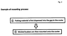
- Figure 2 depicts an exemplary mounting process of the power converter
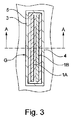
- Figure 3 depicts an example for the bus bar assembly inserted into a cavity
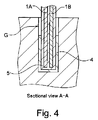
- Figure 4 depicts a sectional view along AA
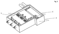
- Figure 5 depicts an assembled power converter according to a preferred example
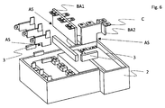
- Figure 6 depicts an exploded view of the power converter
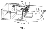
- Figure 7 depicts a sectional view of an assembled power converter
- Figure 8 depicts bus bars inserted into the cavities of the case;
- FIG. 1 shows a power converter assembly according to the claimed subject-matter.
- Bus bar 1 is enveloped in a (plastic) mold 5 to form the bus bar assembly (in the present application the bus bar assembly may be simply called “bus bar”).
- the bus bar 1 is provided for carrying high currents of the power converter assembly and specifically for connecting a power module of the power converter with a capacitor, preferably a smoothing capacitor.
- a capacitor preferably a smoothing capacitor.
- at least one cavity portion 4 is provided in case 2.
- the limited space for mounting the bus bar assembly at the case 2 can be increased by using a vertically extending cavity portion 4 for mounting the bus bar assembly.
- the mounting surface MS of the case 2 is a surface extending basically in a horizontal direction. Horizontal directions are orthogonal to the insertion direction of the bus bar 1, as shown in figure 1. Accordingly, the cavity portion 4 is extending vertically to said horizontal mounting surface MS in the depth-direction or the thickness-direction of the case 2.
- the mounting surface MS may be the bottom surface of a cup-shaped case.
- the bus bar assembly comprises attachment sections AS.
- the attachment sections AS of the bus bar assembly can be inserted into the cavity portions 4 of the case for mounting the bus bar assembly to case 4.
- the attachment section AS is an end part of the bus bar assembly having a plate-shape extending along a projection direction which is a length direction of the bus bar assembly or bus bar.
- the bus bar assembly is inserted into the cavity portion along said projection direction.
- the projection direction is shown by the arrows with the numeral “1” in figure 1.
- the bus bar assembly in figure 1 has two separate attachment sections AS, namely a first end part 5A and a second end part 5B for insertion into the corresponding first and second cavity portions 4A and 4B.
- the bus bar 1 and the plastic mold 5 may suffer a temperature rise during operation of the power converter.
- the bus bar assembly, and more specifically the attachment section AS thereof, is inserted into the cavity portion 4 comprising the thermally conductive material 3.
- the attachment section AS of the bus bar assembly is embedded in thermally conductive material for fixing the bus bar assembly to the case 3 and for improving cooling efficiency of the power converter assembly.
- the heat generated during operation of the bus bar assembly can therefore be conducted from the bus bar assembly via the thermally conductive material to the case 2.
- the case may also function as a heat sink or cooler.
- the bus bar assembly shown in figure 1 has a cross section having a horse shoe shape or U-shape.
- the open end sections of the U-shape are inserted into corresponding cavity portions. Accordingly, the heat transfer can be further improved while at the same time optimized mounting accuracy can be achieved. Mounting can also be facilitated.
- the attachment section AS of the bus bar assembly is inserted along a length direction into the respective cavity portion 4 of the case 2 such that there is preferably a constant gap G between the bus bar assembly and the inner wall of the cavity portion 4.
- thermally conductive material which may include a (thermally conductive) resin, silicon, a thermal conductive elastomer, and/or a gel (thixotropic material).
- the thermally conductive resin may be a liquid resin.
- thermal grease may be used as the thermally conductive material which does not necessarily harden and which at least may not be sufficiently fix the bus bar so that, when thermal grease may be used as thermally conductive material, additional fixation parts, such as screws, are preferably used for fixing the bus bar assembly to the case.
- FIG 2 a diagram with steps for mounting the power converter is shown. Specifically, for the assembly of the power converter the bus bar 1 can be partially inserted in the corresponding cavity portion 4 for improved heat transfer and for optimized arrangement of the bus bar 1. Accordingly, during the assembly of the power converter in a first step the thermally conductive material can be filled into the cavity portion 4. This is shown as step number 1 in the diagram of figure 2.
- the thermally conductive material may be, for example, potting material.
- the bus bar 1 and more specifically the molded bus bar i.e. the bus bar assembly
- the bus bar assembly can be inserted into the cavity portion having the potting material.
- the bus bar assembly is inserted along a length direction of the attachment section. Accordingly, the bus bar assembly can be safely attached to the case 2.
- Case 2 is also referred to as the cooler, since the heat of the bus bar 1 can be transferred to the case for cooling.
- the process of attaching the bus bar assembly to the case 2 may also be automated since the provided cavity portions allow a safe and accurate automated placement of the bus bar assembly on case 2.
- FIG 3 the bus bar assembly inserted into the cavity portion 4 is shown. Between the bus bar assembly and the side wall surfaces of the cavity section 4, a gap G is present. Said gap G is filled with the thermally conductive material 3. Preferably the gap G is completely filled with the thermally conductive material so that no void remains between the bus bar assembly and the cavity section (cavity portion).
- the bus bar assembly in figure 3 comprises a first bus bar 1A and a second bus bar 1B which are embedded collectively in a plastic mold 5.
- the plastic mold 5 completely covers the bus bars in the attachment sections thereof. Accordingly, in a preferable embodiment, the outer surface of the bus bar assembly in the attachment section AS thereof is exclusively formed by the outer surface of the plastic mold 5. Said outer surface of the plastic mold 5 is inserted in the cavity portion 4 and contacted to the thermally conductive material 3 provided in the cavity portion 4.
- Figure 4 shows a sectional view along line AA of figure 3.
- the bus bar assembly is inserted into the cavity portion 4 and surrounded by the thermally conductive material 3.
- a constant gap G or constant trench is formed between the bus bar assembly and the inner wall surface of the cavity portion 4.
- Improved heat conduction behavior and facilitated assembly can be achieved if the thermally conductive material 3 is provided with a constant thickness all around the attachment section (i.e. side surfaces and bottom surface) of the bus bar assembly inserted in the cavity portion 4.
- the constant thickness is also shown in figure 4 and preferably the thickness is between 0.5 and 2 mm.
- the thermally conductive material 3 may be filled into the gap G to partially fill said gap as shown in figure 4 or to completely fill the gap G.
- the cross section of the cavity portion 4 (in the horizontal direction) may have a rectangular shape (in the horizontal and or vertical direction) for providing an improved constant gap around the attachment section.
- the arrangement of the invention it may also be possible to avoid using thermal sheets and instead use exclusively the thermally conductive material for attaching the bus bar assembly.
- Figure 5 shows an embodiment of a power converter according to the invention.
- the electronic components are arranged and mounted.
- electrical connectors are arranged in order to provide an electrical connection with the power converter.
- the capacitor and/or the power module may be arranged in and mounted to the case 2.
- the bus bar assembly is provided.
- several different bus bar assemblies are provided having respective connectors C for the electrical connection.
- the bus bar assembly is arranged in a vertical direction, between adjacent components mounted in the case 2 and parallel to the side surfaces of case 2. Accordingly the bus bar assembly can be mounted perpendicular to the mounting surface of the case 2, which may be the bottom surface of the case and extends in a horizontal direction in figure 5.
- the bus bar and the bus bar assembly is inserted along the length direction of the bus bar into the corresponding cavity portions. In figure 5 the length direction may be parallel to the side wall surfaces of the case 2.
- the bus bar assembly may have the shape of a straight bar, a plate or a vertical bar extending along a length direction which is also the insertion direction. Accordingly, the foot print of the bus bar assembly on the surface of the case can be further reduced.
- the vertical bus bar can be integrated into a die cast casing.
- the bus bar assembly may also have a cross section having an L-shape (the shape of the letter “L”). One end of said L-shaped bus bar can be inserted into the cavity portion for mounting the bus bar assembly to the case.
- Each of the different bus bar assemblies shown in figure 6 has a respective end part which is the attachment section for attaching the respective bus bar assembly to case 2.
- the end part of the bus bar assembly is arranged opposite to the connectors C of the bus bar assembly.
- the bus bar assembly BA1 may have a flat plate shape having the connectors C on one end and the attachment section AS on the opposite end.
- a second bus bar assembly BA2 of figure 6 has a T-shape cross section wherein the connectors C are arranged opposite to the attachment section AS.
- each attachment section AS is pictured with a corresponding thermally conductive material 3. Said thermally conductive material 3 can be provided in the cavity portion of the case 2 prior to the insertion of the attachment section AS into the cavity portion 4.
- FIG 7 a sectional view of an assembled power converter is shown.
- the first and second bus bars 1A, 1B of the bus bar assembly BA1 are inserted into the cavity portion 4 of the case 2.
- the bus bar assembly is mounted to the case 2 exclusively by the connection via the cavity portion 4 and the thermally conductive material 3.
- the thermally conductive material 3 is provided to surround the entire attachment section AS of the bus bar assembly BA1.
- the shape of the cross section (in a direction perpendicular to the insertion direction of the bus bar attachment section) of the cavity may be circular or elliptical for further improving the mounting accuracy.
- the cavity portion may be a molded cavity or a milled cavity.
Landscapes
- Engineering & Computer Science (AREA)
- Microelectronics & Electronic Packaging (AREA)
- Power Engineering (AREA)
- Physics & Mathematics (AREA)
- Thermal Sciences (AREA)
- Inverter Devices (AREA)
- Cooling Or The Like Of Semiconductors Or Solid State Devices (AREA)
Abstract
The present invention relates to a power converter and a method for manufacturing the power converter. The power converter comprises a power module for converting power, a capacitor, a bus bar 1 for connecting the power module with the capacitor, and a case 2 for housing the capacitor. The case 2 has a cavity portion 4 and at least a part of the bus bar 1 is arranged in the cavity portion 4 and the cavity portion 4 comprises a thermally conductive material 3.
Description
The present invention relates to a power converter and a method for manufacturing the power converter.
Conventional power converters have bus bars for carrying high currents which require cooling in order to eliminate melting of plastic molding material which covers the bus bar. Specifically, a power converter usually comprises a power module for converting power and electronic components, such as a capacitor connected thereto. During operation of the power module high temperatures occur which affect the bus bar and the other electronic components, such as the capacitor connected thereto. Accordingly, temperature management may become necessary. For example, cooling of the capacitor and/or the bus bar may become necessary. Conventional bus bars are arranged on thermally conductive, flexible sheets using a large area of the available space/mounting surface of the housing. The high flexibility of these thin sheets further requires that the assembly is performed by hand which is time consuming and difficult to perform.
Patent Literature 1 (JP 2018-166400 A) describes a power conversion device having a switching device for transforming input power. The power conversion device further includes a capacitor for smoothing the input power and a cooler for cooling the switching device and the capacitor.
Accordingly, it is an object of the present invention to provide an improved power converter for overcoming the drawbacks of conventional power converters. For example, it is an object to provide a power converter with an improved cooling efficiency which can be produced in a more efficient manner, preferably in an automated manner. Moreover, it is an object to provide an optimized manufacturing method for the power converter.
To solve the problems, the features of the independent claims are set forth. Preferred developments are described by the dependent claims.
According to an aspect a power converter may comprise a power module for converting power, a capacitor, a bus bar for connecting the power module with the capacitor, and a case for housing the capacitor. The case may have a cavity portion and at least a part of the bus bar may be arranged within or inserted into the cavity portion wherein the cavity portion may comprise a thermally conductive material which was put into the cavity portion. The material, when put into the cavity portion, is very preferably a viscous liquid which can be, e.g., poured into the cavity portion. By providing the thermally conductive material for mounting the bus bar at the case it is possible to improve the heat exchange between the bus bar and the case so that the case can cool the bus bar when in use. After the mounting of the bus bar in the cavity portion, the material preferably hardens and/or dries and may assume a consistence which may be described as rubber-like or the like. The dried and/or hardened thermally conductive material may preferably hold the bus-bar in place and may allow heat transfer between the case and the bus-bar. In a preferred option, the elastic consistence of the material in the hardened state after the assembly allows to endure vibrations and thermal expansion which occur during the use of the power converter, e.g. when used in a vehicle, such as a car.
The thermally conductive material may include a (thermally conductive) resin, silicon, a thermal conductive elastomer, and/or a gel or thixotropic material. The thermally conductive resin may be a liquid resin. Further, in an alternative option thermal grease may be used as the thermally conductive material. Since thermal grease does not necessarily harden to fix the bus bar sufficiently reliable, additional fixation parts, such as screws, may be preferably used for fixing the bus bar assembly to the case in this alternative option.
Moreover, the above arrangement can achieve a facilitated automation in the production of the power converter. With such an arrangement it is also possible to e.g. replace conventional thermal sheets for cooling the bus bars. Preferably the cavity portion extends in a vertical direction to increase the mounting space of the case and improve the cooling properties of the case. Accordingly, a vertical part of the bus bar is inserted into the cavity portion wherein the cavity portion may have at least four side surfaces and a bottom surface. This increased (compared to the conventional thermal sheets) area of thermal transfer surfaces allows improved thermal conductive cooling and the bus-bar can be inserted by machines in a highly automated fashion.
Preferably an end of the bus bar is inserted into the cavity portion and the bus bar is attached to the case via the thermally conductive material in the cavity portion. Accordingly, the bus bar is attached to the case using the thermally conductive material as a filling material in the gap between the inserted part of the bus bar and the inner surface of the cavity portion. The thermally conductive material thereby allows to fix the bus bar or bus bar assembly to the case and improve heat transfer between the bus bar and the case. In order to further improve the connection area between the bus bar or bus bar assembly and the case, the cavity portion is extending in the vertical direction of the case when the horizontal direction is the mounting direction of the electronic parts of the case. With such an arrangement it may therefore be possible to improve the heat transfer and also facilitate the production of the power converter since the bus bar can be easily and securely positioned on the case, in the cavity portion(s). Accordingly it is possible to remove the heat from the bus bar and at the same time automate the production. Preferably the thermally conductive material is elastic. More preferably the thermally conductive material may be electrically insulating.
Preferably the case has a horizontal mounting surface for mounting components such as electronic components and the end or end part of the bus bar is inserted in the cavity portion in a direction which provides an angle larger than 0° to the plane of the mounting surface. More preferably the angle is 90° and most preferably the mounting surface is arranged in a horizontal direction while the bus-bar (part) arranged within the cavity portion extends along a vertical direction. The preferable arrangement of the cavity portion/bus bar achieves, as mentioned above, that the mounting space which is required for the bus bar becomes smaller. The cooling can be enhanced while the area occupied by insulation/cooling means can be reduced.
In accordance with one preferred aspect, the bus bar is inserted into the cavity portion along a length direction of the bus bar. In one or more embodiments the cavity portion may be a bottomed hole or cavity. Preferably the inner sidewall surfaces of the cavity portion may be tapered. More preferably the cavity portion may be a slot hole for improved fixation of the bus bar. Preferably the cavity portion may be manufactured in a casting process or may be a milling groove.
Preferably the end part of the bus bar is a plate-shaped projection or section, extending along a projecting direction and the end part is inserted into the cavity portion along said projecting direction. Moreover, the projection direction is a length direction of the end part.
The cavity portion can be provided on a bottom surface of the case extending in the direction of the bottom-wall thickness direction of the case. Preferably the depth of the cavity portion is deeper than the wall-thickness of the case. The cavity portion may have a bottomed cup shape to reduce the areal footprint of the portion in the case.
Preferably, the bus bar may be at least partially surrounded by a plastic mold to form a bus bar assembly and at least a part of the bus bar assembly may be inserted into the cavity portion to mount the bus bar on the case. Most preferably, the part of the bus bar mounted within the cavity portion is completely surrounded by the thermally conductive material after the thermally conductive material has completely dried. This achieves the best conductive cooling effect and keeps the bus bar reliably within the cavity portion. The mounting process may include that the liquid, (highly) viscous thermally conductive material is placed within the cavity portion and, subsequently, the end-part of the bus bar is inserted into the cavity portion and capillary forces will suck in the liquid to the edge of the cavity opening. As a result, the thermally conductive material surrounds the inserted bus bar part and hardens afterwards. The hardening can be activated/enhanced/started by thermal treatment.
The part of the bus bar assembly inserted into the cavity portion is preferably surrounded by the thermally conductive material. More preferably, the thermally conductive material is provided on at least two opposite sides of the bus bar assembly and/or bus bar. Preferably the thermally conductive material may be provided on at least two adjacent side surfaces of the bus bar assembly and/or bus bar. Accordingly heat can be removed from at least two sides of the bus bar or bus bar assembly.
Preferably, an attachment section of the bus bar assembly is inserted into cavity portion such that the attachment section does not directly contact the case. Accordingly, the thermally conductive material is provided continuously on a circumference of the attachment section. In other words, a gap between the attachment section and the cavity portion is filled with the thermally conductive material. More preferably, the gap between the attachment section and the cavity portion is a constant gap having a constant width which is preferably larger than 0,5mm and smaller than 2mm.
In a further preferably embodiment the bus bar is fixed to the case exclusively by being mounted in the at least one cavity portion. More preferably, the bus bar assembly is attached to the case with the thermally conductive material only. In this case, the thermally conductive material is preferably a material which hardens after some time or after thermal treatment so that the bus bar is held by the hardened material. Preferably, the thermally conductive material in this case my include resin, silicon or the like.
Preferably, the bus bar assembly has an attachment section which is inserted into the cavity portion and the attachment section is a free-end portion of the bus bar assembly. The attachment section may have a circumferential connection-area for contacting the thermally conductive material when mounted in the case and the connection-area is designed such that the temperature of the capacitor can be cooled down to a temperature of 100°C or lower when the power module is operating. Accordingly the extent of the connection-area is designed to allow sufficient heat transfer between the bus bar assembly and the case (or cooler) so that the temperature of a capacitor connected to the bus bar can be kept at or below 100°C when the power converter is operating (preferably in a maximum load case of the power converter).
Preferably, the case has a mounting direction along which electronic components are mounted on the case. The bus bar can be inserted into the cavity portion in a direction different from the mounting direction to further improve the heat connection area while assuring sufficient mounting space for further components to be mounted on the case.
Preferably, the case has a first cavity portion and a second cavity portion and the bus bar has a first end and a second end. For mounting the bus bar at the case the first end is inserted into the first cavity portion and the second end is inserted into the second cavity portion, wherein more preferably the first cavity portion is separate from the second cavity portion. By this arrangement a very stable arrangement of the bus bar can be assured and at the same time the heat transfer can be improved. Moreover, the mounting space can be more efficiently used.
Preferably, the part of the bus bar assembly inserted into the cavity portion is continuously surrounded by the thermally conductive material in order to further improve the heat transfer.
Preferably, the depth of the cavity portion is larger than the wall thickness of the case to further improve the mounting space and heat transfer. In one embodiment the depth of the cavity portion is larger than the largest wall thickness of the case. The depth of the cavity portion may also be larger than the wall thickness of the bottom of the case and/or larger than the smallest wall thickness of the case. The depth of the cavity portion is larger than the wall thickness of the mounting surface of the case. The wall thickness of the case may be the thickness between an outer surface and an inner surface of the case measured perpendicular to the wall extend or body axis or length direction of the wall.
Preferably, the thermally conductive material is provided on at least two different side surfaces of the bus bar assembly. Accordingly it is possible to remove heat from the bus bar from at least two different side surfaces of the bus bar assembly. The side surfaces may extend in a vertical direction (insertion direction) and the bottom surface of the case may extend in a horizontal direction.
In one or more embodiments the cavity portion may be formed on a side surface of the case. The case may be cup-shaped and may have side surfaces and a bottom surface.
Preferably, the bus bar assembly is formed by at least two bus bars arranged parallel to each other, each surrounded, at least partially, by the plastic mold. In the attachment section, preferably, each of the at least two bus bars are provided. The bus bar assembly may include at least two bus bars arranged apart from each other.
Preferably, the cavity portion has at least a side surface and a bottom surface and the area of the bottom surface is smaller than the area of the side surface. The cavity portion may have at least four side surfaces and the total area of the side surfaces may be larger than the area of the bottom surface.
Preferably, the cavity portion is filled partially with the thermally conductive material. More preferably the space between the attachment section and the inner wall surfaces of the cavity section are completely filled with the thermally conductive material.
A method for manufacturing the power converter may comprise the, preferably automated or performed by machines, steps of: dispensing the thermally conductive material into the cavity portion; and inserting the bus bar into the case by accommodating at least an end part of the bus bar within the cavity portion.
The end part of the bus bar may be pressed into the cavity portion such that the thermally conductive material spreads in a gap between the cavity portion and the part bus bar arranged in the cavity portion. Preferably the thermally conductive material spreads to completely fill the gap with material so that no void remains in the gap. Alternatively, the bus bar is not pressed into the cavity portion and the material fills the gap(s) between the case and the bus bar part within the cavity portion only by the action of capillary forces.
Summarizing, a solution is provided which allows to provide an improved electric power converter and a method for manufacturing said power converter. It is a technical benefit that the conventional isolation and thermal conduction sheets, which are difficult to handle during the assembly and which require manual assembly, can be omitted. Instead, the bus bar is at least partially inserted in a cavity portion which encloses the bus bar. In a gap between the case and the bus bar within the cavity portion a thermally conductive material is arranged which enhanced thermal conduction from the bus bar to the case. The footprint area of the bus bar and the thermal conduction means reduces within the case, too.
In the following the subject-matter will be further explained based on at least one preferential example with reference to the attached exemplary drawings, wherein:
In the following section embodiments and preferred aspects are described. However, it is to be understood that they are merely examples that may be embodied in various and alternative forms. The figures are not necessarily to scale wherein some features may be exaggerated or minimized to show details of particular components. Therefore, specific structural and functional details disclosed herein are not to be interpreted as limiting, but merely as a representative basis for teaching one skilled in the art to variously employ the present invention.
Figure 1 shows a power converter assembly according to the claimed subject-matter. Bus bar 1 is enveloped in a (plastic) mold 5 to form the bus bar assembly (in the present application the bus bar assembly may be simply called “bus bar”). The bus bar 1 is provided for carrying high currents of the power converter assembly and specifically for connecting a power module of the power converter with a capacitor, preferably a smoothing capacitor. In order to mount the bus bar assembly at a case 2 of the power converter, at least one cavity portion 4 is provided in case 2.
In order to increase the cooling efficiency and facilitate mounting of the bus bar assembly, the limited space for mounting the bus bar assembly at the case 2 can be increased by using a vertically extending cavity portion 4 for mounting the bus bar assembly. Specifically, the mounting surface MS of the case 2 is a surface extending basically in a horizontal direction. Horizontal directions are orthogonal to the insertion direction of the bus bar 1, as shown in figure 1. Accordingly, the cavity portion 4 is extending vertically to said horizontal mounting surface MS in the depth-direction or the thickness-direction of the case 2. In some embodiments the mounting surface MS may be the bottom surface of a cup-shaped case.
In figure 1 two separate cavity portions 4 are pictured. To mount the bus bar assembly on case 2, the bus bar assembly comprises attachment sections AS. The attachment sections AS of the bus bar assembly can be inserted into the cavity portions 4 of the case for mounting the bus bar assembly to case 4. The attachment section AS is an end part of the bus bar assembly having a plate-shape extending along a projection direction which is a length direction of the bus bar assembly or bus bar. In order to improve the heat transfer and facilitate the mounting process, the bus bar assembly is inserted into the cavity portion along said projection direction. The projection direction is shown by the arrows with the numeral “1” in figure 1. The bus bar assembly in figure 1 has two separate attachment sections AS, namely a first end part 5A and a second end part 5B for insertion into the corresponding first and second cavity portions 4A and 4B.
During the operation of the power converter/bus bar assembly heat is generated. Accordingly, the bus bar 1 and the plastic mold 5 may suffer a temperature rise during operation of the power converter. In order to further improve the heat dissipation of the bus bar assembly, it is suggested to increase the heat transmission between the bus bar assembly and the case 2. Specifically, it is suggested to provide a thermally conductive material 3 in the cavity portion 4 of case 2. The bus bar assembly, and more specifically the attachment section AS thereof, is inserted into the cavity portion 4 comprising the thermally conductive material 3. Accordingly, in the mounted state the attachment section AS of the bus bar assembly is embedded in thermally conductive material for fixing the bus bar assembly to the case 3 and for improving cooling efficiency of the power converter assembly. The heat generated during operation of the bus bar assembly can therefore be conducted from the bus bar assembly via the thermally conductive material to the case 2. The case may also function as a heat sink or cooler.
The bus bar assembly shown in figure 1 has a cross section having a horse shoe shape or U-shape. To connect the bus bar assembly to the case the open end sections of the U-shape are inserted into corresponding cavity portions. Accordingly, the heat transfer can be further improved while at the same time optimized mounting accuracy can be achieved. Mounting can also be facilitated. The attachment section AS of the bus bar assembly is inserted along a length direction into the respective cavity portion 4 of the case 2 such that there is preferably a constant gap G between the bus bar assembly and the inner wall of the cavity portion 4.
It has been found that specifically improved heat transmission properties can be achieved while at the same time secure fixing of the bus bar assembly can be assured by using the following material as thermally conductive material, which may include a (thermally conductive) resin, silicon, a thermal conductive elastomer, and/or a gel (thixotropic material). The thermally conductive resin may be a liquid resin. In an alternative arrangement thermal grease may be used as the thermally conductive material which does not necessarily harden and which at least may not be sufficiently fix the bus bar so that, when thermal grease may be used as thermally conductive material, additional fixation parts, such as screws, are preferably used for fixing the bus bar assembly to the case.
In figure 2 a diagram with steps for mounting the power converter is shown. Specifically, for the assembly of the power converter the bus bar 1 can be partially inserted in the corresponding cavity portion 4 for improved heat transfer and for optimized arrangement of the bus bar 1. Accordingly, during the assembly of the power converter in a first step the thermally conductive material can be filled into the cavity portion 4. This is shown as step number 1 in the diagram of figure 2. The thermally conductive material may be, for example, potting material.
In the following step, as shown in step number 2 in figure 2, the bus bar 1 and more specifically the molded bus bar, i.e. the bus bar assembly, can be inserted into the cavity portion having the potting material. The bus bar assembly is inserted along a length direction of the attachment section. Accordingly, the bus bar assembly can be safely attached to the case 2. Case 2 is also referred to as the cooler, since the heat of the bus bar 1 can be transferred to the case for cooling. The process of attaching the bus bar assembly to the case 2 may also be automated since the provided cavity portions allow a safe and accurate automated placement of the bus bar assembly on case 2.
In figure 3 the bus bar assembly inserted into the cavity portion 4 is shown. Between the bus bar assembly and the side wall surfaces of the cavity section 4, a gap G is present. Said gap G is filled with the thermally conductive material 3. Preferably the gap G is completely filled with the thermally conductive material so that no void remains between the bus bar assembly and the cavity section (cavity portion).
The bus bar assembly in figure 3 comprises a first bus bar 1A and a second bus bar 1B which are embedded collectively in a plastic mold 5. The plastic mold 5 completely covers the bus bars in the attachment sections thereof. Accordingly, in a preferable embodiment, the outer surface of the bus bar assembly in the attachment section AS thereof is exclusively formed by the outer surface of the plastic mold 5. Said outer surface of the plastic mold 5 is inserted in the cavity portion 4 and contacted to the thermally conductive material 3 provided in the cavity portion 4.
Figure 4 shows a sectional view along line AA of figure 3. The bus bar assembly is inserted into the cavity portion 4 and surrounded by the thermally conductive material 3. Preferably a constant gap G or constant trench is formed between the bus bar assembly and the inner wall surface of the cavity portion 4. Improved heat conduction behavior and facilitated assembly can be achieved if the thermally conductive material 3 is provided with a constant thickness all around the attachment section (i.e. side surfaces and bottom surface) of the bus bar assembly inserted in the cavity portion 4. The constant thickness is also shown in figure 4 and preferably the thickness is between 0.5 and 2 mm. The thermally conductive material 3 may be filled into the gap G to partially fill said gap as shown in figure 4 or to completely fill the gap G. The cross section of the cavity portion 4 (in the horizontal direction) may have a rectangular shape (in the horizontal and or vertical direction) for providing an improved constant gap around the attachment section. With the arrangement of the invention it may also be possible to avoid using thermal sheets and instead use exclusively the thermally conductive material for attaching the bus bar assembly.
Figure 5 shows an embodiment of a power converter according to the invention. In case 2 the electronic components are arranged and mounted. On the outer surfaces of case 2 electrical connectors are arranged in order to provide an electrical connection with the power converter. The capacitor and/or the power module may be arranged in and mounted to the case 2. For providing electrical connections to the components mounted in the case 2, the bus bar assembly is provided. In the embodiment shown in figure 5 several different bus bar assemblies are provided having respective connectors C for the electrical connection.
As can be seen in figure 5, the bus bar assembly is arranged in a vertical direction, between adjacent components mounted in the case 2 and parallel to the side surfaces of case 2. Accordingly the bus bar assembly can be mounted perpendicular to the mounting surface of the case 2, which may be the bottom surface of the case and extends in a horizontal direction in figure 5. The bus bar and the bus bar assembly is inserted along the length direction of the bus bar into the corresponding cavity portions. In figure 5 the length direction may be parallel to the side wall surfaces of the case 2.
As shown in figure 6, the bus bar assembly may have the shape of a straight bar, a plate or a vertical bar extending along a length direction which is also the insertion direction. Accordingly, the foot print of the bus bar assembly on the surface of the case can be further reduced. Preferably the vertical bus bar can be integrated into a die cast casing. The bus bar assembly may also have a cross section having an L-shape (the shape of the letter “L”). One end of said L-shaped bus bar can be inserted into the cavity portion for mounting the bus bar assembly to the case.
Each of the different bus bar assemblies shown in figure 6 has a respective end part which is the attachment section for attaching the respective bus bar assembly to case 2. The end part of the bus bar assembly is arranged opposite to the connectors C of the bus bar assembly. As shown in figure 6, the bus bar assembly BA1 may have a flat plate shape having the connectors C on one end and the attachment section AS on the opposite end. A second bus bar assembly BA2 of figure 6 has a T-shape cross section wherein the connectors C are arranged opposite to the attachment section AS. In figure 6 each attachment section AS is pictured with a corresponding thermally conductive material 3. Said thermally conductive material 3 can be provided in the cavity portion of the case 2 prior to the insertion of the attachment section AS into the cavity portion 4.
In figure 7 a sectional view of an assembled power converter is shown. The first and second bus bars 1A, 1B of the bus bar assembly BA1 are inserted into the cavity portion 4 of the case 2. The bus bar assembly is mounted to the case 2 exclusively by the connection via the cavity portion 4 and the thermally conductive material 3. As shown in figure 7 and figure 8, the thermally conductive material 3 is provided to surround the entire attachment section AS of the bus bar assembly BA1. Preferably there is provided a single rectangular cavity portion for fixing one bus bar assembly, as shown in figure 7. In another embodiment the shape of the cross section (in a direction perpendicular to the insertion direction of the bus bar attachment section) of the cavity may be circular or elliptical for further improving the mounting accuracy. The cavity portion may be a molded cavity or a milled cavity.
While exemplary embodiments are described above, it is not intended that these embodiments describe all possible forms of the invention. Rather, the words used in the specification are words of description rather than limitation, and it is understood that various changes may be made without departing from the scope of protection as defined by the claims interpreted on the basis of disclosure provided with the present application. Additionally, the features of various implementing embodiments may be combined to form further embodiments of the invention.
Claims (20)
- A power converter comprising:
an electric power module for converting electric power,
a capacitor,
a bus bar (1) for connecting the power module with the capacitor, and
a case (2) for housing the capacitor,
the power converter characterized by
a cavity portion (4) provided in the case (2), wherein at least a part of the bus bar (1) is arranged in the cavity portion (4) and a thermally conductive material (3) is provided in the cavity portion (4). - The power converter according to claim 1, wherein an end part of the bus bar (1) is arranged within the cavity portion (4) and the bus bar (1) is thermally connected to the case (2) by the thermally conductive material (3).
- The power converter according to claim 2, wherein the end part of the bus bar (1) is a plate-shaped projection extending along a projecting direction and the end part is inserted into the cavity portion (4) along said projecting direction.
- The power converter according to at least one of claims 2 or 3, wherein the case (2) has a mounting surface (MS) for mounting electronic components, and an angle between a plane of the mounting surface (MS) and said projecting direction of the end part of the bus bar (1), when arranged in the cavity portion (4), is larger than 0°.
- The power converter according to any of the preceding claims 1 to 4, wherein the bus bar (1) is at least partially surrounded by a plastic mold (5) to form a bus bar assembly and at least a part of the bus bar assembly is inserted into the cavity portion (4) to mount the bus bar (1) on the case (2).
- The power converter according to claim 5, wherein the bus bar assembly has an attachment section (AS) which is inserted into the cavity portion (4) and the attachment section (AS) is a free-end portion of the bus bar assembly.
- The power converter according to claim 6, wherein the bus bar assembly is inserted into the cavity portion (4) along a length direction of the attachment section (AS).
- The power converter according to any one of claims 1 to 6, wherein the part of the bus bar assembly inserted into the cavity portion (4) is surrounded by the thermally conductive material (3), preferably on at least two opposite sides.
- The power converter according to any one of claims 6 to 8, wherein the attachment section (AS) is inserted into cavity portion (4) such that the attachment section (AS) does not directly contact the case (2).
- The power converter according to any one of claims 1 to 9, wherein the bus bar (1) is fixed to the case (2) exclusively by being mounted in the cavity portion (4) with the thermally conductive material (3).
- The power converter according to claim 1, wherein the case (2) has a mounting direction along which adjacent electronic components are mounted on the case (2) and the bus bar (1) is inserted into the cavity portion (4) in a direction different from the mounting direction.
- The power converter according to any one of the preceding claims 1 to 11, wherein the case (2) has a first cavity portion (4A) and a second cavity portion (4B) and the bus bar (1) has a first end part (5A) and a second end part (5B) and for mounting the bus bar (1) at the case (4) the first end part (5A) is inserted into the first cavity portion (4A) and the second end part (5B) is inserted into the second cavity portion (4B), wherein preferably the first cavity portion (4A) is separate from the second cavity portion (4B).
- The power converter according to any of the preceding claims 1 to 12, wherein the depth of the cavity portion (4) is larger than a wall thickness of the case (2).
- The power converter according to any of the preceding claims 1 to 13, wherein the thermally conductive material (3) is provided on at least two different side surfaces of the bus bar assembly and/or bus bar (1).
- The power converter according to any one of the preceding claims 1 to 14, wherein the cavity portion (4) is formed in a side surface of the case (2).
- The power converter according to any of the preceding claims 1 to 15, wherein the bus bar assembly has a cross section having a horse shoe shape or L-shape.
- The power converter according to any of the preceding claims 1 to 16, wherein a gap (G) is provided between the cavity portion (4) and the part of the bus bar (1) arranged in the cavity portion (4), wherein preferably the gap (G) has a width larger than 0,5mm and/or smaller than 2mm.
- The power converter according to any of the preceding claims 1 to 17, wherein the thermally conductive material (3) is a thermal conductive elastomer.
- Method for manufacturing a power converter according to any of the preceding claims 1 to 18 comprising the steps:
- dispensing the thermally conductive material (3) into the cavity portion (4); and
- molding the bus bar (1) on the case (2) by accommodating at least an end part of the bus bar (1) in the cavity portion (4). - The method according to claim 19, wherein the end part of the bus bar (1) is pressed into the cavity portion (4) such that the thermally conductive material (3) spread in a gap (G) between the cavity portion (4) and the part bus bar (1) arranged in the cavity portion (4).
Priority Applications (2)
| Application Number | Priority Date | Filing Date | Title |
|---|---|---|---|
| CN202080040931.8A CN113939909B (en) | 2019-06-12 | 2020-05-26 | Power converter and method for manufacturing the same |
| JP2021571740A JP7237205B2 (en) | 2019-06-12 | 2020-05-26 | Power converter and method for manufacturing the power converter |
Applications Claiming Priority (2)
| Application Number | Priority Date | Filing Date | Title |
|---|---|---|---|
| DE102019208493.1A DE102019208493A1 (en) | 2019-06-12 | 2019-06-12 | Power converter and method of manufacturing the power converter |
| DE102019208493.1 | 2019-06-12 |
Publications (1)
| Publication Number | Publication Date |
|---|---|
| WO2020250669A1 true WO2020250669A1 (en) | 2020-12-17 |
Family
ID=73546895
Family Applications (1)
| Application Number | Title | Priority Date | Filing Date |
|---|---|---|---|
| PCT/JP2020/020768 Ceased WO2020250669A1 (en) | 2019-06-12 | 2020-05-26 | Power converter and method for manufacturing the power converter |
Country Status (4)
| Country | Link |
|---|---|
| JP (1) | JP7237205B2 (en) |
| CN (1) | CN113939909B (en) |
| DE (1) | DE102019208493A1 (en) |
| WO (1) | WO2020250669A1 (en) |
Cited By (1)
| Publication number | Priority date | Publication date | Assignee | Title |
|---|---|---|---|---|
| CN117895747A (en) * | 2023-12-25 | 2024-04-16 | 深圳市和骏隆电子科技有限公司 | An explosion-proof power adapter |
Citations (5)
| Publication number | Priority date | Publication date | Assignee | Title |
|---|---|---|---|---|
| JP2003007928A (en) * | 2001-06-27 | 2003-01-10 | Nissan Motor Co Ltd | Semiconductor device |
| US20050135065A1 (en) * | 2003-12-19 | 2005-06-23 | Hitachi Industrial Equipment Systems Co., Ltd. | Electric circuit module |
| JP2008125190A (en) * | 2006-11-09 | 2008-05-29 | Auto Network Gijutsu Kenkyusho:Kk | Electrical junction box |
| US20140116751A1 (en) * | 2012-10-31 | 2014-05-01 | Denso Corporation | Bus bar assembly and method of manufacturing the same |
| US20190131883A1 (en) * | 2016-06-21 | 2019-05-02 | Mitsubishi Electric Corporation | Power conversion device |
Family Cites Families (2)
| Publication number | Priority date | Publication date | Assignee | Title |
|---|---|---|---|---|
| US6295201B1 (en) * | 1998-08-04 | 2001-09-25 | Stratos Lightwave, Inc. | Bus bar having embedded switching device |
| JP6145631B2 (en) * | 2012-12-10 | 2017-06-14 | パナソニックIpマネジメント株式会社 | Case mold type capacitor |
-
2019
- 2019-06-12 DE DE102019208493.1A patent/DE102019208493A1/en active Pending
-
2020
- 2020-05-26 CN CN202080040931.8A patent/CN113939909B/en active Active
- 2020-05-26 WO PCT/JP2020/020768 patent/WO2020250669A1/en not_active Ceased
- 2020-05-26 JP JP2021571740A patent/JP7237205B2/en active Active
Patent Citations (5)
| Publication number | Priority date | Publication date | Assignee | Title |
|---|---|---|---|---|
| JP2003007928A (en) * | 2001-06-27 | 2003-01-10 | Nissan Motor Co Ltd | Semiconductor device |
| US20050135065A1 (en) * | 2003-12-19 | 2005-06-23 | Hitachi Industrial Equipment Systems Co., Ltd. | Electric circuit module |
| JP2008125190A (en) * | 2006-11-09 | 2008-05-29 | Auto Network Gijutsu Kenkyusho:Kk | Electrical junction box |
| US20140116751A1 (en) * | 2012-10-31 | 2014-05-01 | Denso Corporation | Bus bar assembly and method of manufacturing the same |
| US20190131883A1 (en) * | 2016-06-21 | 2019-05-02 | Mitsubishi Electric Corporation | Power conversion device |
Cited By (1)
| Publication number | Priority date | Publication date | Assignee | Title |
|---|---|---|---|---|
| CN117895747A (en) * | 2023-12-25 | 2024-04-16 | 深圳市和骏隆电子科技有限公司 | An explosion-proof power adapter |
Also Published As
| Publication number | Publication date |
|---|---|
| CN113939909B (en) | 2026-01-13 |
| JP2022535259A (en) | 2022-08-05 |
| CN113939909A (en) | 2022-01-14 |
| DE102019208493A1 (en) | 2020-12-17 |
| JP7237205B2 (en) | 2023-03-10 |
Similar Documents
| Publication | Publication Date | Title |
|---|---|---|
| JP5569746B2 (en) | Terminal block and nut | |
| JP5736792B2 (en) | Terminal block | |
| JP5630654B2 (en) | Terminal block and method for manufacturing terminal block | |
| JP5534351B2 (en) | Terminal block | |
| EP3379655B1 (en) | Electrical connector and electrical connection arrangement comprising an electrical connector | |
| KR101588578B1 (en) | Improved dissipation of heat from a controller | |
| CN111261597B (en) | Semiconductor element package with high withstand voltage insulation structure | |
| JP3855306B2 (en) | Heat dissipating board for mounting electronic parts and manufacturing method thereof | |
| JP7483963B2 (en) | Power Supplies | |
| JP2011114193A (en) | Bus bar assembly | |
| CN109156090B (en) | Circuit structure | |
| JP6950496B2 (en) | Circuit board and manufacturing method of circuit board | |
| CN110446387B (en) | Electronic unit | |
| JPH047591B2 (en) | ||
| CN113939909B (en) | Power converter and method for manufacturing the same | |
| JP7069733B2 (en) | Heat dissipation block and power converter | |
| CN106449403A (en) | Method for manufacturing large-power IGBT | |
| CN112889352A (en) | Circuit structure and electric connection box | |
| JP2022099045A (en) | Electric connection box | |
| CN114207753B (en) | Capacitor block including spacer | |
| CN211237957U (en) | Electronic assemblies, electronic equipment and their component holders | |
| US20250358986A1 (en) | Electrical device, electric drive system and vehicle | |
| WO2024201979A1 (en) | Circuit structure and method for manufacturing circuit structure | |
| CN113013129B (en) | Power Module | |
| JP2022145648A (en) | electronic device |
Legal Events
| Date | Code | Title | Description |
|---|---|---|---|
| 121 | Ep: the epo has been informed by wipo that ep was designated in this application |
Ref document number: 20823479 Country of ref document: EP Kind code of ref document: A1 |
|
| ENP | Entry into the national phase |
Ref document number: 2021571740 Country of ref document: JP Kind code of ref document: A |
|
| NENP | Non-entry into the national phase |
Ref country code: DE |
|
| 122 | Ep: pct application non-entry in european phase |
Ref document number: 20823479 Country of ref document: EP Kind code of ref document: A1 |