WO2020250461A1 - ガス監視装置、該方法および該プログラム - Google Patents
ガス監視装置、該方法および該プログラム Download PDFInfo
- Publication number
- WO2020250461A1 WO2020250461A1 PCT/JP2019/048710 JP2019048710W WO2020250461A1 WO 2020250461 A1 WO2020250461 A1 WO 2020250461A1 JP 2019048710 W JP2019048710 W JP 2019048710W WO 2020250461 A1 WO2020250461 A1 WO 2020250461A1
- Authority
- WO
- WIPO (PCT)
- Prior art keywords
- gas
- detection
- image
- mask
- unit
- Prior art date
- Legal status (The legal status is an assumption and is not a legal conclusion. Google has not performed a legal analysis and makes no representation as to the accuracy of the status listed.)
- Ceased
Links
Images




Classifications
-
- G—PHYSICS
- G01—MEASURING; TESTING
- G01M—TESTING STATIC OR DYNAMIC BALANCE OF MACHINES OR STRUCTURES; TESTING OF STRUCTURES OR APPARATUS, NOT OTHERWISE PROVIDED FOR
- G01M3/00—Investigating fluid-tightness of structures
- G01M3/02—Investigating fluid-tightness of structures by using fluid or vacuum
- G01M3/04—Investigating fluid-tightness of structures by using fluid or vacuum by detecting the presence of fluid at the leakage point
-
- G—PHYSICS
- G01—MEASURING; TESTING
- G01M—TESTING STATIC OR DYNAMIC BALANCE OF MACHINES OR STRUCTURES; TESTING OF STRUCTURES OR APPARATUS, NOT OTHERWISE PROVIDED FOR
- G01M3/00—Investigating fluid-tightness of structures
- G01M3/002—Investigating fluid-tightness of structures by using thermal means
-
- G—PHYSICS
- G06—COMPUTING OR CALCULATING; COUNTING
- G06T—IMAGE DATA PROCESSING OR GENERATION, IN GENERAL
- G06T7/00—Image analysis
- G06T7/0002—Inspection of images, e.g. flaw detection
- G06T7/0004—Industrial image inspection
- G06T7/0008—Industrial image inspection checking presence/absence
-
- G—PHYSICS
- G08—SIGNALLING
- G08B—SIGNALLING SYSTEMS, e.g. PERSONAL CALLING SYSTEMS; ORDER TELEGRAPHS; ALARM SYSTEMS
- G08B21/00—Alarms responsive to a single specified undesired or abnormal condition and not otherwise provided for
- G08B21/02—Alarms for ensuring the safety of persons
- G08B21/12—Alarms for ensuring the safety of persons responsive to undesired emission of substances, e.g. pollution alarms
-
- G—PHYSICS
- G08—SIGNALLING
- G08B—SIGNALLING SYSTEMS, e.g. PERSONAL CALLING SYSTEMS; ORDER TELEGRAPHS; ALARM SYSTEMS
- G08B25/00—Alarm systems in which the location of the alarm condition is signalled to a central station, e.g. fire or police telegraphic systems
-
- G—PHYSICS
- G06—COMPUTING OR CALCULATING; COUNTING
- G06T—IMAGE DATA PROCESSING OR GENERATION, IN GENERAL
- G06T2207/00—Indexing scheme for image analysis or image enhancement
- G06T2207/10—Image acquisition modality
- G06T2207/10048—Infrared image
-
- G—PHYSICS
- G06—COMPUTING OR CALCULATING; COUNTING
- G06T—IMAGE DATA PROCESSING OR GENERATION, IN GENERAL
- G06T2207/00—Indexing scheme for image analysis or image enhancement
- G06T2207/30—Subject of image; Context of image processing
- G06T2207/30108—Industrial image inspection
Definitions
- the present invention relates to a gas monitoring device, a gas monitoring method, and a gas monitoring program for monitoring the presence or absence of a predetermined gas in a space.
- a gas detection device that detects a predetermined gas existing in the space can be used to monitor the presence or absence of the predetermined gas in the space.
- This gas detection device is disclosed in, for example, Patent Document 1.
- the gas detection image processing device disclosed in Patent Document 1 is a device that performs image processing on an infrared image obtained by capturing a gas leak monitoring target at a plurality of times, and shows a temperature change due to the leaked gas. It is provided with an image processing unit that performs processing for removing the second frequency component data, which has a lower frequency than the first frequency component data and indicates a temperature change of the background to be monitored, from the image data indicating the infrared image.
- gas detection uses temperature changes due to absorption of infrared rays, it may mistakenly detect sparkle due to sunlight reflection as temperature fluctuation due to gas, or mistakenly detect an object that reflects a heat source as gas. In some cases.
- the plant has equipment that releases heat-exchanged steam, which may mistakenly detect the released steam or steam as a gas.
- gas monitoring for example, when performing a predetermined work such as removal or leakage countermeasures, if the gas detection is a false alarm, for example, preparation for carrying out the predetermined work or gas is detected.
- a predetermined action for carrying out the predetermined work such as moving to a place where the gas is performed, is wasted.
- the present invention has been made in view of the above circumstances, and an object of the present invention is to provide a gas monitoring device, a gas monitoring method, and a gas monitoring program capable of reducing false alarms.
- the gas monitoring device, the gas monitoring method, and the gas monitoring program reflecting one aspect of the present invention detect the presence or absence of a predetermined gas based on the image of the monitored object and issue a notification. It accepts the input of predetermined additional information including the notification presence / absence information indicating whether or not to do so, and determines whether or not to suppress the notification with gas detected by the detection based on the received additional information.
- the first modification as an example, it is a figure for demonstrating the past additional information display screen displayed on the gas monitoring apparatus.
- the second modification as an example, it is a figure for demonstrating the mask image display screen displayed on the gas monitoring apparatus. It is a figure for demonstrating the mask image in the 3rd modification. It is a figure for demonstrating the position of the center of gravity of the gas region in the 4th modification. It is a figure for demonstrating each generation process of a mask candidate image and a mask image in the 4th modification. It is a figure for demonstrating the alarm processing of gas detection using a mask image in the 4th modification. It is a time chart for demonstrating each generation process of a mask candidate image and a mask image in the 5th modification.
- the ninth modified form as an example, it is a figure for demonstrating the gas detection image and additional information used for machine learning.
- the gas monitoring device in the embodiment is a device that monitors the presence or absence of gas in the monitored object and notifies the presence of gas to the outside when the presence or absence of gas is detected.
- the monitoring target is, for example, a storage facility for storing a predetermined gas, a utilization facility for using the predetermined gas (for example, a gas power plant, a gas processing plant, etc.), a distribution facility for supplying and distributing the predetermined gas, and the like.
- a gas monitoring device has a gas detection unit that detects the presence or absence of a predetermined gas based on an image of the monitored object, and whether or not to issue a alarm, in order to reduce false alarms.
- a notification suppression determination unit for determining.
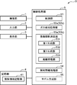
- FIG. 1 is a block diagram showing a configuration of a gas monitoring device according to an embodiment.
- a gas monitoring device D includes, for example, an imaging unit 1, an input unit 2, a display unit 3, a storage unit 4, and a control processing unit 5.
- the imaging unit 1 is a device connected to the control processing unit 5 and, in accordance with the control of the control processing unit 5, images the monitored object and generates an image (image data) of the monitored object, a so-called camera.
- the image pickup unit 1 and the control processing unit 5 may be connected by wire, may be wirelessly connected, or may be connected via a network.
- the imaging unit 1 outputs the generated image of the monitoring target to the control processing unit 5, and the control processing unit 5 stores the image of the monitoring target in the storage unit 4.
- the imaging unit 1 images the monitored object in an appropriate wavelength band according to the gas detection method.
- the imaging unit 1 captures an image to be monitored in an infrared wavelength band. It is an infrared camera that produces an image to be monitored by infrared rays.
- known methods such as the method disclosed in Japanese Patent No. 5343504 (Japanese Patent Laid-Open No. 2012-058093) and the method disclosed in International Publication No. 2017/073426 can be used. ..
- the input unit 2 is connected to the control processing unit 5, and is connected to, for example, various commands such as a command for instructing the start of gas monitoring, and various data necessary for monitoring the monitoring target such as input of an identifier in the monitoring target.
- a device for inputting data to the gas monitoring device D for example, a plurality of input switches to which predetermined functions are assigned, a keyboard, a mouse, and the like. Then, in the present embodiment, when the presence of gas is detected as described later, the input unit 2 accepts the input of predetermined additional information including the notification presence / absence information indicating whether or not to issue a notification.
- the display unit 3 is connected to the control processing unit 5, and according to the control of the control processing unit 5, commands and data (including the additional information) input from the input unit 2 and a mask image generated as described later.
- Etc. such as a CRT display, an LCD (liquid crystal display), an organic EL display, and the like.
- the storage unit 4 is a circuit connected to the control processing unit 5 and stores various predetermined programs and various predetermined data under the control of the control processing unit 5.
- the various predetermined programs include a control program that controls each unit 1 to 4 of the gas monitoring device D according to the function of each unit, and a predetermined gas based on an image of the monitored object captured by the imaging unit 1.
- a gas detection processing program that detects the presence or absence, and a notification suppression determination program that determines whether or not to suppress the notification of the presence of gas detected by the gas detection processing program based on the additional information received by the input unit 2.
- the input unit 2 accepts the input of predetermined additional information, and in the image, the detection portion where the presence of gas is detected by the gas detection processing program is associated with the additional information received by the input unit 2 as detection information.
- a control processing program such as a detection information processing program stored in the storage unit 4 is included.
- the various predetermined data include data necessary for executing each program, such as an image captured by the imaging unit 1, a gas detection image, a mask candidate image, and a mask image.
- the storage unit 4 includes, for example, a ROM (Read Only Memory) which is a non-volatile storage element, an EEPROM (Electrically Erasable Programmable Read Only Memory) which is a rewritable non-volatile storage element, and the like.
- the storage unit 4 includes a RAM (Random Access Memory) or the like that serves as a working memory of the so-called control processing unit 5 that stores data or the like generated during execution of the predetermined program.
- the storage unit 4 may include a hard disk device having a relatively large storage capacity. Then, in the present embodiment, the storage unit 4 functionally includes the detection information storage unit 41.
- the detection information storage unit 41 stores the detection information.
- the detection information storage unit 41 detects the presence of gas by the gas detection processing unit 52a, which will be described later, in association with the additional information received by the input unit 2 in the image.
- the additional information includes notification presence / absence information indicating whether or not to issue a notification.
- the additional information further includes cause information indicating the cause that the gas detection processing unit 52a has detected that there is gas, confirmer information indicating the confirmer who input the additional information from the input unit 2, and the said. Includes input date and time information representing the date and time when additional information is input from the input unit 2.
- the notification presence / absence information includes information with notification indicating that the information is issued and information without notification indicating that the information is not issued.
- the cause information includes, for example, vapor that may be erroneously detected as a gas, a shadow of the vapor, an unknown cause, and the like.
- the confirmer information is, for example, the name of the confirmer, an identifier for identifying and identifying the confirmer (confirmer ID), or the like.
- the control processing unit 5 controls each unit 1 to 4 of the gas monitoring device D according to the function of each unit, monitors the presence or absence of gas in the monitored object, and when the presence or absence of gas is detected, the input unit 2 accepts it. This is a circuit for notifying the presence of gas based on whether or not to suppress the issuance, which is determined based on the additional information.
- the control processing unit 5 includes, for example, a CPU (Central Processing Unit) and peripheral circuits thereof.
- the control processing unit 5 functionally includes the control unit 51, the gas detection processing unit 52a, the alarm suppression determination unit 53a, and the detection information processing unit 54 when the control processing program is executed.
- the control unit 51 controls each unit 1 to 4 of the gas monitoring device D according to the function of each unit, and controls the entire gas monitoring device D.
- the gas detection processing unit 52a detects the presence or absence of a predetermined gas based on the image of the monitored object captured by the imaging unit 1.
- the gas detection processing unit 52a generates a gas detection image showing the presence or absence of gas for each pixel by a known gas detection method.
- the method disclosed in International Publication No. 2017/0743430 (Patent Document 1) is used.
- the apparatus disclosed in Patent Document 1 first obtains second frequency component data, which has a lower frequency than the first frequency component data indicating the temperature change due to the leaked gas and indicates the temperature change of the background to be monitored. The process of removing from the image data indicating the infrared image is executed.
- the image data is moving image data having a structure in which a plurality of frames are arranged in a time series
- the apparatus obtains data in which pixel data of a plurality of pixels at the same position of the frame are arranged in a time series.
- the time-series pixel data is used, and each of the plurality of time-series pixel data constituting the moving image data is processed to remove the second frequency component data.
- the apparatus uses data extracted by performing the first predetermined processing on the time-series pixel data as the second frequency component data, and a plurality of data corresponding to each of the plurality of time-series pixel data.
- the second frequency component data of the above is extracted.
- the apparatus uses the data obtained by calculating the difference between the time-series pixel data and the second frequency component data extracted from the time-series pixel data as the first difference data, and a plurality of the time-series. A plurality of the first difference data corresponding to each of the pixel data are calculated. The apparatus obtains data indicating fluctuations in the first difference data, which is calculated by performing a predetermined calculation on the first difference data in units of the second predetermined number of frames. As the first variation data, a plurality of the first variation data corresponding to each of the plurality of time series pixel data are calculated. The first variation data is the first variation data, and the apparatus moves the first difference data in units of the second predetermined number of frames, which is less than the plurality of frames.
- the first variation data is obtained by calculating the standard deviation or the movement variance. Then, the apparatus detects the presence or absence of gas for each pixel by determining the first variation data with a given threshold value. For example, the presence or absence of gas is expressed by the brightness, the pixel indicating the presence or absence of gas is a white or colored pixel, and the pixel indicating the absence of gas is a black pixel. In this way, the gas detection image is generated.
- the detection information processing unit 54 receives input of predetermined additional information to the detection portion where the gas detection processing unit 52a has detected the presence of gas in the image by the input unit 2, and the input unit 2 receives the input of predetermined additional information to the detection unit.
- the received additional information is associated and stored as detection information in the detection information storage unit 41 of the storage unit 4.
- the detection information processing unit 54 accepts the input of additional information and stores the detection information based on the input in the storage unit 4.
- the alarm suppression determination unit 53a suppresses the alarm with gas detected by the gas detection processing unit 52a based on the additional information received by the input unit 2 for a predetermined period (including one input). It decides whether or not. Then, when the gas detection processing unit 52a detects the presence of gas, the notification suppression determination unit 53a suppresses the notification of the presence of gas detected by the gas detection processing unit 52a if the determination is suppression. On the other hand, if the determination is not suppressed, the presence of gas detected by the gas detection processing unit 52a is notified to the outside.
- the alarm suppression determination unit 53a functionally includes the first generation unit 531, the second generation unit 532, and the alarm processing unit 533.
- the first generation unit 531 generates a mask candidate image as a candidate for the mask image based on the detection information stored in the detection information storage unit 41 for a predetermined period.
- the second generation unit 532 generates the mask image by using a mask portion that satisfies a predetermined mask condition as a mask in the mask candidate image generated by the first generation unit 531.
- the final mask image is generated after the mask candidate image is generated. More specifically, the first generation unit 531 generates the mask candidate image by setting the detection portion associated with the additional information having the alert presence / absence information indicating that the alarm is not issued as the mask candidate portion.
- the predetermined mask condition is appropriately set from, for example, a plurality of samples.
- the predetermined mask condition is set in advance as an aggregation result obtained by aggregating the issue presence / absence information indicating that the issue is not issued for the detection portion and the additional information for the predetermined period. It is equal to or higher than a predetermined threshold value (for example, a mask determination threshold value such as 2 times, 3 times, 4 times, etc.). Therefore, in the present embodiment, the second generation unit 532 performs each processing by the detection information processing unit 54 and the first generation unit 531 during the predetermined period, and then for each of the detection unit and the additional information.
- a predetermined threshold value for example, a mask determination threshold value such as 2 times, 3 times, 4 times, etc.
- the issue presence / absence information indicating that the alarm is not issued is aggregated, the aggregated result is compared with the mask determination threshold value, and the mask candidate portion whose aggregated result is equal to or greater than the mask determination threshold value is determined as the mask portion.
- the final mask image is generated by using the determined mask portion as a mask.
- Such a mask portion may be permanently used as a mask until the use of the mask image is finished, but in the present embodiment, a lifetime is set, and the second generation unit 532 is the mask portion. After the lapse of a predetermined fourth period (lifetime) from the time when the mask is used (that is, the time when it is determined to suppress the alarm), the mask portion is finished as a mask.
- the notification suppression determination unit 53a suppresses the notification for a predetermined fourth period from the time when it is determined to suppress the notification.
- the predetermined period and the predetermined fourth period are appropriately set from, for example, a plurality of samples, respectively.
- the predetermined period is set to 3 days, 5 days, 7 days, etc.
- the predetermined 4th period is set to 5 days, 7 days, 10 days, etc.
- the alarm processing unit 533 processes the alarm of the gas detection result using the mask image.
- the alarm processing unit 533 uses a mask image as the gas detection image and displays the mask-processed gas detection image (gas detection image after the mask processing) on the display unit 3 as described later. Issue a report.
- the mask process is a process of deleting the image detected as gas in order not to issue the detection of gas to the mask region, as will be described later. As a result, the notification is suppressed.
- the input unit 2, the display unit 3, the storage unit 4, and the control processing unit 5 in such a gas monitoring device D can be configured by, for example, a tablet type, a notebook type, and a desktop type computer.
- the image pickup unit 1 and the gas detection processing unit 52a correspond to an example of a gas detection unit that detects the presence or absence of a predetermined gas based on an image of the monitored object.
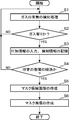
- FIG. 2 is a flowchart showing the operation of the gas monitoring device.
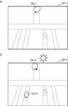
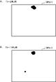
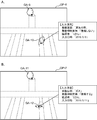
- FIG. 3 is a diagram for explaining a gas detection image to be monitored, which is used in the gas monitoring device as an example.
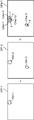
- FIG. 3A schematically shows a gas detection image including one false positive gas region
- FIG. 3B schematically shows a gas detection image including two false positive gas regions.
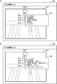
- FIG. 4 is a diagram for explaining an additional information input screen displayed on the gas monitoring device as an example.
- FIG. 4A shows an additional information input screen before inputting the additional information
- FIG. 4B shows an additional information input screen after inputting the additional information.
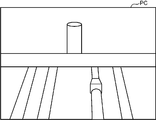
- FIG. 5 is a diagram for explaining a visible image when the monitored object is photographed in the visible wavelength band as an example.
- FIG. 5 is a diagram for explaining a visible image when the monitored object is photographed in the visible wavelength band as an example.
- FIG. 6 is a diagram for explaining a mask candidate image generation process performed by the gas monitoring device.
- FIG. 7 is a diagram for explaining a mask image generation process performed by the gas monitoring device.
- FIG. 7A shows a mask candidate image as an example
- FIG. 7B shows a mask image generated from the mask candidate image shown in FIG. 7A.
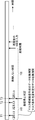
- FIG. 8 is a time chart for explaining each of the mask candidate image and the mask image generation process performed by the gas monitoring device.
- control processing unit 5 is functionally configured with the control unit 51, the gas detection processing unit 52a, the alarm suppression determination unit 53a, and the detection information processing unit 54.
- the gas monitoring device D executes a gas presence / absence detection process (S1). More specifically, the control processing unit 5 acquires an image of the monitoring target generated by imaging the monitoring target by the imaging unit 1 from the imaging unit 1, and the gas detection processing unit 52a captures the monitoring target. Generate a gas detection image from the image.
- the gas monitoring device D determines whether or not the presence of gas is detected in the process S1 by the detection information processing unit 54 (S2). As a result of this determination, if the presence of gas is detected (Yes), the gas monitoring device D then executes the process S3, while the result of the determination is that the presence of gas is not detected (No). The gas monitoring device D returns the process to the process S1. For example, in the present embodiment, a gas detection image indicating the presence or absence of gas is generated for each pixel by the gas detection processing unit 52a in the process S1, so that any pixel in the gas detection image is a pixel indicating the presence or absence of gas.
- the gas monitoring device D determines that the presence of gas is detected, while the gas monitoring device D determines that the presence of gas is not detected when all the pixels in the gas detection image are pixels indicating no gas. To do. For example, when the gas detection image GP-1 shown in FIG. 3A is generated by the gas detection processing unit 52a in the process S1, the gas detection image GP-1 is located at positions adjacent to each other and has a plurality of pixels with gas. In this process S2, the gas monitoring device D determines that the presence of gas has been detected, and then executes the process S3 because the gas region GA-1 formed by combining the above is included.
- the equipment gas equipment
- FIG. 5 the corresponding positional relationship between FIGS. 3 and 5 can be easily grasped.
- FIG. 3 the gas facility shown in FIG. 5 is shown by a broken line. The same applies to the following.
- the gas monitoring device D receives the input of additional information by the detection information processing unit 54 and stores the detection information in the storage unit 4.
- the detection information processing unit 54 displays an additional information input screen on the display unit 3.
- the additional information input screen 60 is a screen for inputting additional information.
- a gas detection image display area 61 for displaying a gas detection image and an addition for inputting additional information. It includes an information input area 62.
- the additional information input region 62 is provided on the additional information input screen 60 as a newly opened window in the vicinity of the gas region GA (gas region GA-1 in the example shown in FIG. 4).
- the additional information is the issue presence / absence information, the cause information, the confirmer information, and the input date / time information, as described above. Therefore, the additional information input area 62 inputs the cause information accordingly.
- Notification cause input area 621 notification suppression presence / absence input area 622 for inputting notification presence / absence information
- confirmation person input area 623 for inputting confirmer information
- input date / time input for inputting input date / time information.
- a region 624 is provided. For example, when the cursor is set to each area 621 to 624 and each information is input to each area 621 to 624 from the keyboard on the additional information input screen 60 before inputting the additional information shown in FIG. 4A, FIG. 4B The additional information input screen 60 after the input of the additional information shown in the above is displayed on the display unit 3.
- a pull-down menu displaying a list of input candidates corresponding to the areas 621 to 624 is displayed, and one of the input candidates displayed in this list is selected. By selecting, each information may be input to each area 621 to 624.
- the detection information processing unit 54 inputs it to the detection portion where the gas detection processing unit 52a detects the presence of gas in the image, and in the present embodiment, to the gas region GA.
- the additional information received in the unit 2 is associated with the additional information and stored in the detection information storage unit 41 as the detection information.
- the gas monitoring device D determines whether or not a predetermined period has elapsed. As a result of this determination, when the predetermined period has elapsed, the gas monitoring device D then executes the process S5, while as a result of the determination, when the predetermined period has not elapsed. The gas monitoring device D returns the process to the process S1. As a result, the detection information is collected, stored in the detection information storage unit 41, and accumulated for a predetermined period.
- the gas monitoring device D generates a mask candidate image by the first generation unit 531 based on the detection information stored in the detection information storage unit 41 for the predetermined period. More specifically, first, the first generation unit 531 sets the mask candidate image as the mask candidate portion by setting the detection portion associated with the additional information having the alert presence / absence information indicating that the alarm is not issued as the mask candidate portion. Generate.
- the gas detection image GP-1 including one gas region GA-1 shown in FIG. 3A is generated, and the gas region GA-1 is generated. Additional information including issuance presence / absence information indicating that the alarm is not issued is associated and stored in the detection information storage unit 41 as detection information, and gas detection including the two gas regions GA-2 and GA-3 shown in FIG. 3B.
- the image GP-2 is generated, and each additional information including the notification presence / absence information indicating that the notification is not issued is associated with each of the gas region GA-2 and the gas region GA-3, and the detection information storage unit is used as the detection information.
- the first generation unit 531 sets the gas region GA-1 of the detection portion as the candidate portion CAa-1 and the gas region GAa-2 of the detection portion as the candidate portion CAa.
- a mask candidate image CPa-1 is generated by setting the value to -2 and setting the gas region GA-3 of the detection portion as the candidate portion CAa-3.
- Such generation of the candidate portion CAa is performed on all the detection information stored in the detection information storage unit 41, and the final mask candidate image CPa is generated.
- the gas region GA-1 is a region in which water vapor is erroneously detected as a gas
- the gas region GA-2 is a region in which water vapor is erroneously detected as a gas
- the gas region GA-3 is a region in which the shadow of water vapor due to the sun is erroneously detected as a gas.
- the gas monitoring device D generates a mask image by the second generation unit 532 by using a mask portion satisfying a predetermined mask condition as a mask in the mask candidate image. , Stored in the storage unit 4. More specifically, the second generation unit 532 aggregates the issue presence / absence information indicating that the issue is not issued for each detection portion (gas region GA in this example) and additional information, and this aggregation result and the mask determination threshold value.
- the final mask image is generated by determining the candidate portion of the mask whose total result is equal to or higher than the mask determination threshold value as the mask portion and using the determined mask portion as the mask.
- the candidate portion CAa-1 ( The candidate portion CAa-12 in which the original gas region GA-1) and the candidate portion CAa-2 (original gas region GA-2) overlap is counted as 2 times, and the number of times is counted as 2 times, and the number of times is counted as 2 times.
- the number of times for each pixel belonging to the candidate portion CAa-12 is twice.
- the number of times of the candidate part CAa-1 and the candidate part CAa-2 excluding the overlapping candidate part CAa-12 is counted as one, and the overlapping candidate part CAa-12 is added according to the totaling result.
- the number of times for each pixel belonging to the candidate portion CAa-1 and the candidate portion CAa-2 to be excluded is one.
- the number of times of the candidate portion CAa-3 original gas region GA-3) is counted as one, and the number of times of each pixel belonging to the candidate portion CAa-3 is counted as one according to the totaling result. Become. Such aggregation is performed on all the detection information stored in the detection information storage unit 41.
- each pixel whose aggregation result is equal to or greater than the mask determination threshold value is determined to be a mask portion and is used as a mask.
- each aggregation result in each pixel belonging to the two candidate portions CAa-1 and CAa-2 is determined to be mask portions MK-1 and MK-2, respectively, and are used as masks, while each belonging to the candidate portion CAa-3.
- the candidate portion CAa-3 is not determined to be the mask portion MK and is not used as a mask.
- the mask image MPa shown in FIG. 7B is generated from the mask candidate image CPa-2 shown in FIG. 7A.
- FIG. 7A the difference in the number of times of aggregation results is shown due to the difference in hatching.
- the gas monitoring device D By operating in this way, the gas monitoring device D generates a mask image.
- the predetermined period is 3 days
- the mask determination threshold is 3 times
- the predetermined 4th period is 7 days
- a certain detection portion in the image to be monitored is shown in FIG.
- the time T1, the time T2, and the time T3 in each of the above-mentioned processes S1 to S3, which are repeatedly executed from the start of mask image generation, do not issue an alarm to the certain detection portion.
- the certain detection portion is subjected to the execution of each of the above-described processes S5 and S6, which are executed after three days have elapsed from the start of mask image generation.
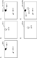
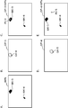
- FIG. 9 is a diagram for explaining a notification process of gas detection using a mask image.
- 9A schematically shows a mask image
- FIG. 9B shows a gas detection image
- FIG. 9C shows a gas by masking the gas detection image shown in FIG. 9B with the mask image shown in FIG. 9A.
- FIG. 9D shows a gas detection image
- FIG. 9E shows a gas detection by masking the gas detection image shown in FIG. 9D with the mask image shown in FIG. 9A. Indicates the case of reporting.
- the following operations are repeatedly executed at predetermined sampling intervals, and the monitored target is monitored.
- the gas monitoring device D acquires the current image from the imaging unit 1, and the gas detection processing unit 52a of the control processing unit 5 generates the current gas detection image from the current original image.
- the gas monitoring device D masks the gas detection image this time by the alarm processing unit 533 using the mask image, and generates a gas detection image after the mask processing. More specifically, first, the alarm processing unit 533 determines whether or not the gas detection image this time includes a gas region indicating gas detection. As a result of this determination, if the gas region is not included, the present processing is terminated, while if the gas region is included, the alarm processing unit 533 is stored in the storage unit 4. Take out (call) the mask image that is being used. For example, the mask image MPa shown in FIG. 9A is taken out.
- the alarm processing unit 533 determines, for each pixel belonging to the gas region, whether or not the pixel of the mask image at the same pixel position as the pixel position of the pixel is a mask pixel. As a result of this determination, the alarm processing unit 533 determines that the ratio of the pixels determined to be mask pixels to the gas region is equal to or greater than a preset second threshold value (issue permission / rejection determination threshold). Deletes the gas region from the gas detection image, while does not delete the gas region when the ratio of the pixels determined to be mask pixels is less than the notification permission / rejection determination threshold. For example, as shown in FIGS. 9C and 9E, the mask image MPa shown in FIG. 9A is superimposed on the gas detection image GP-3 shown in FIG.
- the gas region is deleted from the gas detection image, while the ratio of the gas region overlapping the mask region is the notification permission / rejection judgment threshold value. If it is less than, the gas region is not deleted. More specifically, as shown in FIG. 9C, the gas region GA-4 whose ratio is equal to or higher than the notification permission / rejection threshold value is deleted and not notified, and as shown in FIG. 9E, the ratio is the notification.
- the gas region GA-5 which is less than the permission / rejection threshold value, is notified without being deleted.
- the alarm processing unit 533 notifies the presence of gas by displaying the gas detection image after the mask processing on the display unit 3.
- Mask processing is performed by such an operation, and the presence of gas is notified.
- the gas monitoring device D in the embodiment and the gas monitoring method and gas monitoring program implemented therein accept input of predetermined additional information including notification presence / absence information indicating whether or not to issue a report. , It is determined whether or not to suppress the notification of the presence of gas based on the received additional information for a predetermined period. Therefore, the gas monitoring device D, the gas monitoring method, and the gas monitoring program receive input from the observer (user, operator) after considering, for example, the cause of detection and the continuity of subsequent alarms. , Since it is possible to reduce the number of alarms determined to be unnecessary while using the gas monitoring device, false alarms can be reduced.
- the gas monitoring device D, the gas monitoring method, and the gas monitoring program include the detection information storage unit 41, the consideration of the monitor can be stored (recorded), and even if the monitor is changed, the change is made.
- the observer can refer to the previous consideration and can reduce the false alarm with continuous consideration.
- the gas monitoring method, and the gas monitoring program since the additional information includes the cause information, it is possible to decide to suppress the issuance in consideration of the cause information, and it is possible to reduce false alarms. Further, in the gas monitoring device D, the gas monitoring method, and the gas monitoring program, since the additional information includes the confirmer information, it is possible to determine the suppression of the issuance in consideration of the confirmer information, and it is possible to reduce false alarms.
- the gas monitoring device D, the gas monitoring method, and the gas monitoring program suppress the alarm only during the fourth period, the suppression of the alarm can be applied to changes in the monitoring target with the passage of time.
- the gas monitoring device D may display the detection information received by the input unit 2 in the past by the control processing unit 5 and stored in the detection information storage unit 41 on the display unit 3. (First modified form). Such a gas monitoring device D can refer to the past detection information, and can be referred to when inputting the additional information this time.
- FIG. 10 is a diagram for explaining a past additional information display screen displayed on the gas monitoring device as an example in the first modified form.
- the control processing unit 5 displays the past additional information display screen 70 shown in FIG. 10 on the display unit 3.
- the past additional information display screen 70 is a screen for displaying past additional information.
- a monitoring target image display area 71 for displaying a monitoring target image generated by the imaging unit 1 and past additional information.
- the past additional information display area 72 for displaying is provided. In the past additional information display area 72, for example, when a part (designated part, a broken line elliptical part in the example shown in FIG.
- the control processing unit 5 provides the past additional information display screen 70 as a newly opened window in the vicinity of the designated portion.
- the past additional information display area 72 includes an issue cause display area 721 for displaying cause information, an issue suppression presence / absence display area 722 for displaying issue presence / absence information, and a confirmer display for displaying confirmer information.
- An area 723 and an input date / time display area 724 for displaying input date / time information are provided.
- the designated portion is used as a detection portion, and the cause information, the presence / absence information of the alarm, and the confirmer in the past additional information stored in the detection information storage unit 41 associated with the detection portion are used. Information and input date and time information are displayed respectively.
- the plurality of additional information can be displayed in a list or by sequentially switching the display contents of the respective areas 721 to 724. Additional information may be displayed in sequence.
- the gas monitoring device D may display the suppression portion determined by the notification suppression determination unit to suppress the notification on the display unit 3 in the image (second). Modified form).
- a gas monitoring device can refer to the current suppression part of the alarm in the image.
- the suppression of the issuance is performed by the mask portion of the mask image MPa, so that the mask portion corresponds to an example of the suppression portion, and the mask image generated by the second generation unit 532. By displaying the MPa on the display unit 3, the suppression portion is displayed on the display unit 3.
- FIG. 11 is a diagram for explaining a mask image display screen displayed on the gas monitoring device as an example in the second modified form.
- the control processing unit 5 displays the mask image display screen 80 shown in FIG. 11 on the display unit 3.
- the mask image display screen 80 is a screen for displaying the current mask image MPa, for example, a mask image display area 81 for displaying the current mask image MPa stored in the storage unit 4, and the current mask image display area 81. It includes an effective remaining days display area 82 for displaying the effective remaining days of the mask image MPa.
- the effective remaining days display area 82 is newly opened by the control processing unit 5 in the vicinity of the mask portion.
- the mask image display screen 80 is provided as a window.
- the number of days from the day when the mask image display screen 80 is displayed to the end date of the predetermined fourth period is displayed in the predetermined fourth period.
- the date of expiration date may be displayed.
- the notification suppression determination unit 53a indicates that the notification is not issued for each of a plurality of time zones different from each other by the first and second generation units 531 and 532.
- the number of times of information is totaled, a mask image MPa is generated for each of the plurality of time zones, and the alarm suppression determination unit 53a includes the capture time of the gas detection image in the gas detection image by the alarm processing unit 533.
- the mask image MP of the time zone may be used for mask processing, and the gas detection image after the mask processing may be displayed on the display unit 3 (third modified form).
- FIG. 12 is a diagram for explaining a mask image in the third modified form.
- the mask image MPa-1 in the time zone from 0:00 to 2:00 shown in FIG. 12A and the mask image MPa-2 in the time zone from 9:00 to 11 shown in FIG. 12B are generated.
- mask image MPa in other time zones may be generated.
- Some changes in the monitoring target change according to the time zone, such as a change in the direction of solar radiation with respect to the monitoring target. Since such a gas monitoring device D, a gas monitoring method, and a gas monitoring program aggregate for each of a plurality of time zones and generate a mask image MPa for each of them, a more appropriate mask image MPa can be generated according to the time zone. ..
- the gas monitoring device D includes a gas detection processing unit 52a and a gas region as a detection unit, but the gas detection processing unit 52b is provided instead of the gas detection processing unit 52a.
- the pixel at the center of gravity of the gas region may be used as the detection portion (fourth modified form). That is, in this fourth modified form, the detection portion is a pixel at the position of the center of gravity of the gas region formed by combining a plurality of pixels with gas at positions adjacent to each other.
- Such a gas monitoring device D can associate the additional information with each other in units of the center of gravity of the gas region.
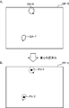
- FIG. 13 is a diagram for explaining the position of the center of gravity of the gas region in the fourth modified form.
- FIG. 13A schematically shows a gas detection image in which two gas regions are detected
- FIG. 13B shows the position of the center of gravity of each gas region shown in FIG. 13A.
- FIG. 14 is a diagram for explaining each of the mask candidate image and the mask image generation process in the fourth modified form.
- FIG. 14A is a diagram for explaining each generation process of the mask candidate image
- FIG. 14B is a diagram schematically showing the mask image as an example.
- the outline of the gas region is shown by a broken line.
- FIG. 13B and FIG. 14A the outline of the gas region is shown by a broken line.
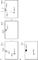
- FIG. 15 is a diagram for explaining a notification process of gas detection using a mask image in the fourth modified form.
- FIG. 15A schematically shows a mask image
- FIG. 15B shows a gas detection image
- FIG. 15C shows a gas by masking the gas detection image shown in FIG. 15B with the mask image shown in FIG. 15A.
- FIG. 15D shows a gas detection image
- FIG. 15E notifies the gas detection by masking the gas detection image shown in FIG. 15D with the mask image shown in FIG. 15A. Show the case.
- the gas detection processing unit 52b obtains the gas region GA by the same processing as the gas detection processing unit 52a, obtains the center of gravity position of the obtained gas region GA, and obtains the center of gravity position of the obtained gas region.
- the pixel corresponding to is obtained as the detection portion.
- the position of the center of gravity of the gas region is, for example, a coordinate average value
- the X coordinate is obtained by dividing the sum of the X coordinate positions of all the pixels of the gas region by the number of pixels in the gas region
- the Y coordinate is , It is obtained by dividing the sum of the Y coordinate positions of all the pixels in the gas region by the number of pixels in the gas region.
- the center of gravity position Pc-1 of the gas region GA-6 and the gas region GA-7 as shown in FIG. 13B is obtained.
- the position of the center of gravity of the gas region is not limited to the above-mentioned calculation method, and may be obtained by another calculation method.
- the first generation unit 531 masks by using the detection portion (here, the pixel at the center of gravity of the gas region) associated with the additional information having the alert presence / absence information indicating that the alarm is not issued as the mask candidate portion.
- Generate a candidate image For example, in FIG. 14A, a gas detection image PP-1 including the center of gravity positions Pc-1 and Pc-2 of the two gas regions is generated, and each pixel of the center of gravity positions Pc-1 and Pc-2 of the two gas regions is generated.
- Additional information including the presence / absence information indicating that the alarm is not issued is associated with each other and stored in the detection information storage unit 41 as detection information, and the gas detection image PP- including the center of gravity position Pc-3 of one gas region.
- the first generation unit 531 uses the pixel of the center of gravity position Pc-1 of the gas region as the detection portion as the candidate portion CAb-1, and the pixel of the center of gravity position Pc-2 of the gas region as the detection portion as the candidate portion CAb-.
- the mask candidate image CPb-1 is generated by setting the pixel of the center of gravity position Pc-3 of the gas region as the detection portion as the candidate portion CAb-3. Such generation of the candidate portion CAb is performed on all the detection information stored in the detection information storage unit 41, and the final mask candidate image CPb is generated.
- the second generation unit 532 sets the mask image CPb as a mask portion that satisfies a predetermined mask condition in the mask candidate image CPb in the same manner as described above. Is generated and stored in the storage unit 4. More specifically, the second generation unit 532 aggregates the issue presence / absence information indicating that the alarm is not issued for each detection portion (pixel at the center of gravity position of the gas region in this example) and additional information, and this aggregation result. Is compared with the mask determination threshold value, a mask candidate portion whose total result is equal to or greater than the mask determination threshold value is determined to be a mask portion, and the determined mask portion is used as a mask to generate the mask image.
- the presence / absence information indicating that the notification is not issued is aggregated for each detection portion and for each pixel of the center of gravity position Pc of the gas region in this example.
- Candidate portion CAb-1 (pixel of the center of gravity position Pc-1 of the original gas region), candidate portion CAb-2 (pixel of the center of gravity position Pc-2 of the original gas region) and candidate portion CAb-3 (original gas region) The number of times for each pixel of the center of gravity position Pc-3) is counted as one, and the number of times for each pixel of each of the candidate portions CAb-1 to CAb-3) is once according to the counting result. (Since the candidate portion CAb is the position Pc of the center of gravity of the gas region, it is one pixel). Such aggregation is performed on all the detection information stored in the detection information storage unit 41.
- a mask image MPb having two mask portions MK-3 and MK-4 shown in FIG. 14B is generated.
- the mask portions MK-3 and MK-4 are shown as regions formed by combining a plurality of mask pixels located adjacent to each other into one.
- the alarm processing unit 533 masks the gas detection image using a mask image as follows, and displays the gas detection image after the mask processing on the display unit 3 to perform the alarm. More specifically, first, the alarm processing unit 533 determines whether or not the gas detection image this time includes a gas region indicating gas detection. As a result of this determination, if the gas region is not included, the present processing is terminated, while if the gas region is included, the alarm processing unit 533 is stored in the storage unit 4. Take out the mask image. For example, the mask image MPb shown in FIG. 15A is taken out. Next, the alarm processing unit 533 obtains a pixel at the position of the center of gravity of the gas region for each gas region included in the gas detection image.
- the alarm processing unit 533 determines whether or not the pixel at the center of gravity of the gas region is a mask pixel for each gas region included in the gas detection image. As a result of this determination, the alarm processing unit 533 deletes the gas region from the gas detection image when it is a mask pixel, and does not delete the gas region when it is not a mask pixel. For example, as shown in FIGS. 15C and 15E, the mask image MPb shown in FIG. 15A is superimposed on the gas detection image GP-3 shown in FIG. 15B so as to have the same pixel positions, and the center of gravity position Pc of the gas region GA-4 is superimposed.
- the gas region GA-4 is deleted from the gas detection image GP-3 and is not notified, while the center of gravity position Pc of the gas region GA-5. If -5 is neither a pixel in the mask portion MK-3 nor a pixel in the mask portion MK-4, the gas region GA-5 is notified without being deleted. Then, when such mask processing is completed, the alarm processing unit 533 notifies the presence of gas by displaying the gas detection image after the mask processing on the display unit 3.
- the gas monitoring device D collects data for creating a mask candidate image CP (CPa, CPb) by the mask generation unit 55a including the first generation unit 531.
- Data for determining whether or not the mask condition is satisfied is collected at the same time during the predetermined period (for example, the data collection period for creating the mask candidate image shown in FIG. 8 and the data collection period for determining the satisfaction of the mask condition).
- the mask generation unit 55a including the first generation unit 531 generated the mask candidate image CP and the mask image MP (MPa, MPb) based on the detection information collected in the predetermined period. As shown in FIG.
- the gas monitoring device D collects data for creating the mask candidate image CP to generate the mask candidate image CP during the data collection period for creating the mask candidate image, and generates the mask candidate image CP.
- the mask image MP may be generated by collecting the data for determining whether or not the mask condition is satisfied during the data collection period of the mask condition satisfaction determination (fifth modified form).
- Such a gas monitoring device D, a gas monitoring method, and a gas monitoring program can automatically generate a mask candidate image CP based on a totaled result of totaling the number of detections of detecting the presence of gas.
- the first generation unit 531 in such a gas monitoring device D is based on a plurality of images captured at a plurality of different times in a predetermined third period (data collection period for creating a mask candidate image) set in advance.
- the mask candidate image is generated based on the aggregation result obtained by totaling the number of detections of detecting the presence of gas in a predetermined aggregation unit.
- the predetermined third period may be appropriately set using, for example, a plurality of samples, but in order to generate a more appropriate mask candidate image, the predetermined period is longer than the predetermined period. Is also preferable.
- the gas monitoring device D monitors the presence or absence of gas in the monitored target, and when it detects the presence or absence of gas, it determines that there is gas.
- the gas region GA (instead of the gas region GA, the position of the center of gravity of the gas region may be used) is associated with each other and stored in the storage unit 4.
- the first generation unit 531 totals the number of detections of gas presence for each pixel, and for each pixel, the number of detections of gas presence and a predetermined predetermined number of detections.
- the pixel When compared with three threshold values (candidate determination threshold values) and as a result of this comparison, when the number of detections of the gas is equal to or greater than the candidate determination threshold value, the pixel is used as a mask candidate portion (mask candidate pixel), while the said As a result of comparison, when the number of detections of the gas is less than the candidate determination threshold value, the pixel is not used as the candidate portion of the mask.
- the candidate determination threshold value (the predetermined third threshold value) is appropriately preset from a plurality of samples, for example.
- the mask candidate image CPc shown in FIG. 16B is generated.
- This mask candidate image CPc includes two candidate portions CA-1 and CA-2.
- the gas monitoring device D executes each of the above-described processes S1 to S4 described with reference to FIG. 2, and stores the detection information in the detection information storage unit 41. go. Then, when the data collection period for determining the satisfaction of the mask condition is completed, the gas monitoring device D receives the mask candidate image generated by the second generation unit 532 from the data collected in the predetermined third period in the same manner as described above. In addition, for each of the detection portion and the additional information, the issue presence / absence information indicating that the alarm is not issued is aggregated, the aggregated result is compared with the mask determination threshold, and the aggregated result is equal to or greater than the mask determination threshold.
- the mask image is generated by determining a candidate portion of a mask as a mask portion and using the determined mask portion as a mask. For example, in the mask candidate image CPc shown in FIG. 16B, the candidate portion CA-1 is determined to be a mask portion when the totalization result is equal to or higher than the mask determination threshold value, and the candidate portion CA-2 has the totalization result. It is less than the mask determination threshold value and is not determined to be a mask portion, and as a result, as shown in FIG. 16C, a mask image MPc containing the candidate portion CA-1 as the mask portion MK is generated.
- the end time of the data collection period for creating the mask candidate image and the end time of the data collection period for the mask condition satisfaction determination coincide with each other, and the data collection period for creating the mask candidate image is the mask condition satisfaction determination. Since it is longer than the data collection period of, the data collection period of mask candidate image creation is started before the start time of the data collection period of mask condition satisfaction judgment, and the mask is masked during the data collection period of mask candidate image creation. The data collection period for determining the condition satisfaction is started. It should be noted that the end time of the data collection period for creating the mask candidate image and the end time of the data collection period for determining the satisfaction of the mask condition do not necessarily have to be exactly the same, but the data collection period for creating the mask candidate image is the latest. It is desirable that it is a new time in order to generate a mask candidate image that reflects the situation of.
- the additional information is input from the input unit 2 each time when the presence of gas is detected, but in the gas monitoring device D, the input unit 2 is a predetermined number. It may be configured to collectively accept the input of additional information in two periods (sixth modified form).
- Such a gas monitoring device D, a gas monitoring method, and a gas monitoring program can collectively input additional information, and can reduce the troublesomeness of input by a user (operator).
- the gas monitoring device D when the gas monitoring device D detects the presence of gas, it stores the gas detection image in the storage unit 4 in association with the detection time, and stores a predetermined input timing (for example, one hour before the end of working hours, etc.). ), The gas detection images stored in the storage unit 4 from the previous input timing to the current input timing are sequentially displayed on the additional information input screen 60, the input of the additional information is sequentially accepted, and the detection thereof. Information is sequentially stored in the detection information storage unit 41. Alternatively, when the gas monitoring device D detects the presence of gas, the gas detection image is stored in the storage unit 4 in association with the detection time, and when a predetermined input timing is reached, the previous input timing to the current input timing is reached.
- a predetermined input timing for example, one hour before the end of working hours, etc.
- a detection frequency image as shown in FIG. 7A is generated and displayed on the additional information input screen 60, and additional information is input for each aggregated detection portion.
- the detection information is sequentially received and the detection information is sequentially stored in the detection information storage unit 41.
- additional information from the previous input timing to the current input timing is collectively input. According to this, additional information can be input even when the presence of gas is detected while the user is absent (for example, during non-working hours).
- the alarming suppression determination unit 52a determines that the detection portion does not issue an alarm, even if the alarming of pixels within a predetermined distance from the detection portion is suppressed. good. According to this, since not only the detection portion but also the peripheral pixels of the detection portion are not notified, the enlargement can be performed as compared with the case where only the detection portion is not notified (7th modified form).
- the second generation unit 532 of the notification suppression determination unit 52a determines whether or not the mask condition is satisfied for each pixel of the mask candidate image generated by the first generation unit 531, and satisfies the mask condition.
- the mask image is generated by using the corresponding pixel and peripheral pixels within a predetermined distance from the corresponding pixel as the mask portion and the mask portion as the mask.
- a gas monitoring device D a gas monitoring method, and a gas monitoring program, not only the pixel but also the peripheral pixels of the pixel are used as the mask portion, so that the mask portion is enlarged as compared with the case where only the pixel is used as the mask portion. it can.
- the detection portion is a pixel at the position of the center of gravity of the gas region, it is preferable to use such a seventh modified form.
- the alerting suppression determination unit 52a aggregates the alerting presence / absence information indicating that the alert is not issued for each of the detection portion and the additional information for the predetermined period.
- the length (period length) of the fourth period may be determined based on the obtained second tabulation result (eighth modified form). For example, the larger (larger) the second tabulation result (the number of notification presence / absence information indicating that the notification is not issued), the longer the fourth period is set. The larger the number of notification presence / absence information indicating that the notification is not issued, the higher the probability that the detection portion will continuously suppress the notification, and whether or not the detection portion is suppressed. There is little need to make a new judgment.
- Such a gas monitoring device D, a gas monitoring method, and a gas monitoring program determine the length of the fourth period based on the second total result obtained by totaling the notification presence / absence information indicating that the notification is not issued. Therefore, it is possible to determine whether or not to suppress the alarm at a more appropriate timing (timing).
- the gas monitoring device D is machine-learned based on the additional information received by the input unit 2 for a predetermined period instead of the alarm suppression determination unit 53a.
- a machine learning model that determines whether or not to suppress the notification of the presence of gas detected by the gas detection processing unit 52 (52a, 52b).
- a notification suppression determination unit 53b for determining (9th modified form).
- a known machine learning model can be used as the machine learning model, and for example, a convolutional neural network (CNN) is used.
- CNN convolutional neural network
- Such a gas monitoring device D, a gas monitoring method, and a gas monitoring program can determine whether or not to suppress the notification of the presence of gas detected by the gas detection processing unit 52 by using the machine learning model.
- FIG. 17 is a diagram for explaining a gas detection image and additional information used for machine learning as an example in the ninth modified form.
- FIG. 17A shows the first sample and
- FIG. 17B shows the second sample.
- the gas monitoring device D uses the detection information stored in the detection information storage unit 41 and the gas detection image used for detecting the detection portion of the detection information, as shown by the broken line in FIG.
- the control processing unit 5 may be further functionally provided with a model generation unit 55 that generates the machine learning model by the machine learning.
- the model generation unit 55 machine-learns a machine learning model before machine learning by using the detection information stored in the detection information storage unit 41 and the gas detection image used for detecting the detection portion of the detection information. Then, a machine learning model after machine learning is generated, and the machine learning model after machine learning is stored in the storage unit 4.
- the gas detection images GP-6 and GP-7 shown in FIG. 17 and the detection information corresponding thereto are so-called learning data.
- the notification presence / absence information serves as a teacher (answer) for the gas region of the gas detection image and the pixel at the position of its center of gravity. Since the notification presence / absence information includes the notification presence / absence information as shown in FIG. 17A and the notification presence / absence information as shown in FIG. 17B, the machine is based on the learning data including such notification presence / absence information.
- the machine learning model after the machine learning can issue only a region in the gas detection image that the observer desires to issue. In other words, the machine learning model after the machine learning can suppress the alarm in the region where the observer does not want the alarm in the gas detection image.
- the shapes of the gas regions GA-9 to GA-12 may also be used as the learning data.
- the predetermined period is uniformly started and the predetermined fourth period is started for the entire pixel in the mask image MPa, but each pixel in the mask image MPa is started.
- the predetermined period is started when additional information including the presence / absence information indicating that the alarm is not issued is first associated with the image, and after the end of the predetermined period, the mask condition is satisfied to obtain a mask image.
- the predetermined fourth period may be started, while the predetermined period may be started again when the mask image is not obtained without satisfying the mask condition (10th modified form).
- repair history information may be added as additional information.
- additional information an image at the time of gas leakage may be added.
- the gas leak image is selected and saved, and can be played back when the past additional information is displayed.
- it may be automatically linked and saved at the time of issuing a report (12th modified form).
- an example is described as a fixed camera that captures a specific field of view throughout, but it can also be applied to a pan-tilt camera that periodically monitors a plurality of fields of view. ..
- the above mask and machine learning model are individually applied to each field of view.
- the gas monitoring device is a device that monitors the presence or absence of gas in the monitored object and notifies the presence of gas when the presence or absence of gas is detected, and is based on an image obtained by capturing the image of the monitored object.
- a gas detection unit that detects the presence or absence of a predetermined gas
- an input unit that accepts input of predetermined additional information including notification presence / absence information indicating whether or not to issue an alarm, and additional information received by the input unit.
- the gas detection unit is provided with a notification suppression determination unit that determines whether or not to suppress the notification with gas detected by the gas detection unit.
- a gas monitoring device accepts input of predetermined additional information including notification presence / absence information indicating whether or not to issue a report, and suppresses the notification with gas based on the received additional information. Decide whether or not. Therefore, the gas monitoring device can be used while using the gas monitoring device by accepting input from a monitor (user, operator) after considering, for example, the cause of detection and the continuity of subsequent alarms. , Since it is possible to reduce the number of reports that are determined to be unnecessary, it is possible to reduce false alarms.
- the detection portion where the presence of gas is detected by the gas detection unit is associated with the additional information received by the input unit and stored as detection information. It further includes a detection information storage unit.
- Such a gas monitoring device further includes a detection information storage unit, it is possible to memorize (record) the consideration of the observer, and even if the observer is changed, the changed observer is the previous one.
- the consideration can be referred to, and with continuous consideration, the false alarm can be reduced.
- the gas detection unit detects the presence or absence of gas for each pixel of the image, and the detection portions are located at positions adjacent to each other and have gas. It is a pixel at the position of the center of gravity of the gas region formed by combining the pixels of.
- Such a gas monitoring device can associate the additional information with the position of the center of gravity of the gas region.
- the additional information includes cause information indicating the cause of the gas detection unit detecting the presence of gas.
- the additional information includes the cause information, it is possible to determine the suppression of the issuance in consideration of the cause information and reduce the false alarm.
- the input unit collectively receives the input of additional information in a predetermined second period.
- Such a gas monitoring device can input additional information collectively, and can reduce the troublesomeness of input by the observer.
- the alarm suppression determination unit when the alarm suppression determination unit determines that the detection portion does not issue an alarm, the alarm suppression determination unit suppresses the alarm of pixels within a predetermined distance from the detection portion. To do.
- the alarm suppression determination unit has gas in the gas detection unit based on a plurality of images taken at a plurality of different times in a predetermined third period. Based on the totaling result obtained by totaling the number of detections in which the above is detected in a predetermined totaling unit, it is determined whether or not to suppress the issuance.
- the alarm suppression determination unit generates a mask candidate image that is a candidate for a mask image that suppresses the detected notification with gas, based on the additional information received by the input unit for a predetermined period.
- the second generation unit that generates the mask image and the detection unit by using the mask portion that satisfies a predetermined mask condition as a mask.
- a notification processing unit that determines whether or not to issue a notification of the presence or absence of gas in the detection portion by masking the mask image, and the first generation units mutually in a predetermined third period.
- the mask candidate image is generated based on the totalization result obtained by totaling the number of detections of gas presence detected by the gas detection unit based on a plurality of images captured at a plurality of different times in a predetermined totalization unit. To do.
- Such a gas monitoring device can automatically generate the mask candidate image based on the total result of totaling the number of detections of detecting the presence of gas.
- the alarm suppression determination unit suppresses the alarm for a predetermined fourth period from the time when it is determined to suppress the alarm.
- the notification suppression determination unit aggregates the notification presence / absence information indicating that the notification is not issued for each of the detection portion and the additional information for the predetermined period.
- the length of the fourth period is determined based on the aggregation result obtained by.
- the gas monitoring device determines the length (period length) of the fourth period based on the second aggregation result obtained by aggregating the notification presence / absence information indicating that the notification is not issued, so that the timing is more appropriate. At (timing), it can be determined whether or not the alarm is suppressed.
- the above-mentioned gas monitoring device further includes a display unit that displays the detection information stored in the detection information storage unit.
- Such a gas monitoring device is provided with a display unit, it is possible to refer to past detection information and to refer to it when inputting the additional information this time.
- the gas monitoring device described above further includes a second display unit that displays a suppression portion determined by the notification suppression determination unit to suppress the notification in the image.
- the alarm suppression determination unit is machine-learned based on the additional information received by the input unit for a predetermined period, and the gas detected by the gas detection unit.
- a machine learning model that determines whether or not to suppress the presence of gas, it is determined whether or not to issue the presence of gas detected by the gas detection unit.
- Such a gas monitoring device can determine whether or not to suppress the notification of the presence of gas detected by the gas detection unit using a machine learning model.
- the gas monitoring method is a method of monitoring the presence or absence of gas in the monitoring target and issuing a notification of the presence of gas when the presence or absence of gas is detected, and is an image obtained by capturing the image of the monitoring target.
- a gas detection step that detects the presence or absence of a predetermined gas based on the above, an input step that accepts input of predetermined additional information including notification presence / absence information indicating whether or not to issue a report, and additional information received in the input step.
- a notification suppression determination step for determining whether or not to suppress the notification with gas detected in the gas detection step is provided.
- the gas monitoring program is a program that monitors the presence or absence of gas in the monitoring target and issues the presence of gas when the presence or absence of gas is detected.
- a gas detection unit that detects the presence or absence of a predetermined gas based on an captured image, an input unit that accepts input of predetermined additional information including notification presence / absence information indicating whether or not to issue an alarm, and an input unit that accepts the input.
- This is a gas monitoring program for functioning as a notification suppression determination unit that determines whether or not to suppress the notification of the presence of gas detected by the gas detection unit based on the additional information.
- Such a gas monitoring method and a gas monitoring program accept the input of predetermined additional information including the notification presence / absence information indicating whether or not to issue a notification, and based on the received additional information, the notification with gas is issued. Decide whether or not to suppress. Therefore, the gas monitoring method and the gas monitoring program receive input from a monitor (user, operator) after considering, for example, the cause of detection and the continuity of subsequent alarms, thereby performing the gas monitoring method. And while using the gas monitoring program, it is possible to reduce false alarms because it is determined that they are unnecessary.
- a gas monitoring device for monitoring the presence or absence of a predetermined gas in a space.
Landscapes
- Engineering & Computer Science (AREA)
- Physics & Mathematics (AREA)
- General Physics & Mathematics (AREA)
- Emergency Management (AREA)
- Business, Economics & Management (AREA)
- Environmental & Geological Engineering (AREA)
- Health & Medical Sciences (AREA)
- General Health & Medical Sciences (AREA)
- Toxicology (AREA)
- Quality & Reliability (AREA)
- Computer Vision & Pattern Recognition (AREA)
- Theoretical Computer Science (AREA)
- Emergency Alarm Devices (AREA)
- Examining Or Testing Airtightness (AREA)
- Alarm Systems (AREA)
Priority Applications (3)
| Application Number | Priority Date | Filing Date | Title |
|---|---|---|---|
| EP19932817.0A EP3985373A4 (en) | 2019-06-11 | 2019-12-12 | GAS MONITORING DEVICE, METHOD AND PROGRAM |
| JP2021525898A JP7416064B2 (ja) | 2019-06-11 | 2019-12-12 | ガス監視装置、該方法および該プログラム |
| US17/618,408 US12253433B2 (en) | 2019-06-11 | 2019-12-12 | Gas monitoring device, method, and program |
Applications Claiming Priority (2)
| Application Number | Priority Date | Filing Date | Title |
|---|---|---|---|
| JP2019108534 | 2019-06-11 | ||
| JP2019-108534 | 2019-06-11 |
Publications (1)
| Publication Number | Publication Date |
|---|---|
| WO2020250461A1 true WO2020250461A1 (ja) | 2020-12-17 |
Family
ID=73780940
Family Applications (1)
| Application Number | Title | Priority Date | Filing Date |
|---|---|---|---|
| PCT/JP2019/048710 Ceased WO2020250461A1 (ja) | 2019-06-11 | 2019-12-12 | ガス監視装置、該方法および該プログラム |
Country Status (4)
| Country | Link |
|---|---|
| US (1) | US12253433B2 (cg-RX-API-DMAC7.html) |
| EP (1) | EP3985373A4 (cg-RX-API-DMAC7.html) |
| JP (1) | JP7416064B2 (cg-RX-API-DMAC7.html) |
| WO (1) | WO2020250461A1 (cg-RX-API-DMAC7.html) |
Families Citing this family (1)
| Publication number | Priority date | Publication date | Assignee | Title |
|---|---|---|---|---|
| CN117789420B (zh) * | 2023-12-28 | 2025-02-14 | 沭阳华润燃气有限公司 | 一种新型计量数据采集系统 |
Citations (9)
| Publication number | Priority date | Publication date | Assignee | Title |
|---|---|---|---|---|
| JPS5343054B2 (cg-RX-API-DMAC7.html) | 1972-01-28 | 1978-11-16 | ||
| JPS6245418B2 (cg-RX-API-DMAC7.html) | 1978-08-14 | 1987-09-26 | Goodyear Aerospace Corp | |
| JP2000101987A (ja) * | 1998-09-18 | 2000-04-07 | Oki Electric Ind Co Ltd | 火災検知装置 |
| JP2012058093A (ja) | 2010-09-09 | 2012-03-22 | Mitsubishi Electric Building Techno Service Co Ltd | ガス漏れ検出装置 |
| WO2017073426A1 (ja) | 2015-10-29 | 2017-05-04 | コニカミノルタ株式会社 | 漏洩ガス検出装置および漏洩ガス検出方法 |
| WO2017073430A1 (ja) | 2015-10-29 | 2017-05-04 | コニカミノルタ株式会社 | ガス検知用画像処理装置、ガス検知用画像処理方法及びガス検知用画像処理プログラム |
| WO2018110036A1 (ja) * | 2016-12-16 | 2018-06-21 | コニカミノルタ株式会社 | ガス状態判別方法とそれに用いる画像処理装置及び画像処理プログラム |
| WO2019044898A1 (ja) * | 2017-08-31 | 2019-03-07 | コニカミノルタ株式会社 | ガス検知システム |
| JP2019108534A (ja) | 2017-12-18 | 2019-07-04 | エルジー・ケム・リミテッド | コア‐シェル共重合体の製造方法、コア‐シェル共重合体およびこれを含む樹脂組成物 |
Family Cites Families (5)
| Publication number | Priority date | Publication date | Assignee | Title |
|---|---|---|---|---|
| US20080092625A1 (en) * | 2004-07-27 | 2008-04-24 | Michele Hinnrichs | Gas Leak Detector Having An Integral Data Logger |
| US7358860B2 (en) * | 2005-03-31 | 2008-04-15 | American Air Liquide, Inc. | Method and apparatus to monitor and detect cryogenic liquefied gas leaks |
| WO2014176693A1 (en) * | 2013-04-29 | 2014-11-06 | Intelliview Technologies Inc. | Object detection |
| WO2017179599A1 (ja) | 2016-04-14 | 2017-10-19 | コニカミノルタ株式会社 | ガス監視プログラム、システム、記録媒体及び方法 |
| IL253638A0 (en) * | 2017-07-24 | 2017-09-28 | Shalom Swissa Shai | Leak detection system |
-
2019
- 2019-12-12 JP JP2021525898A patent/JP7416064B2/ja active Active
- 2019-12-12 EP EP19932817.0A patent/EP3985373A4/en active Pending
- 2019-12-12 WO PCT/JP2019/048710 patent/WO2020250461A1/ja not_active Ceased
- 2019-12-12 US US17/618,408 patent/US12253433B2/en active Active
Patent Citations (9)
| Publication number | Priority date | Publication date | Assignee | Title |
|---|---|---|---|---|
| JPS5343054B2 (cg-RX-API-DMAC7.html) | 1972-01-28 | 1978-11-16 | ||
| JPS6245418B2 (cg-RX-API-DMAC7.html) | 1978-08-14 | 1987-09-26 | Goodyear Aerospace Corp | |
| JP2000101987A (ja) * | 1998-09-18 | 2000-04-07 | Oki Electric Ind Co Ltd | 火災検知装置 |
| JP2012058093A (ja) | 2010-09-09 | 2012-03-22 | Mitsubishi Electric Building Techno Service Co Ltd | ガス漏れ検出装置 |
| WO2017073426A1 (ja) | 2015-10-29 | 2017-05-04 | コニカミノルタ株式会社 | 漏洩ガス検出装置および漏洩ガス検出方法 |
| WO2017073430A1 (ja) | 2015-10-29 | 2017-05-04 | コニカミノルタ株式会社 | ガス検知用画像処理装置、ガス検知用画像処理方法及びガス検知用画像処理プログラム |
| WO2018110036A1 (ja) * | 2016-12-16 | 2018-06-21 | コニカミノルタ株式会社 | ガス状態判別方法とそれに用いる画像処理装置及び画像処理プログラム |
| WO2019044898A1 (ja) * | 2017-08-31 | 2019-03-07 | コニカミノルタ株式会社 | ガス検知システム |
| JP2019108534A (ja) | 2017-12-18 | 2019-07-04 | エルジー・ケム・リミテッド | コア‐シェル共重合体の製造方法、コア‐シェル共重合体およびこれを含む樹脂組成物 |
Non-Patent Citations (1)
| Title |
|---|
| See also references of EP3985373A4 |
Also Published As
| Publication number | Publication date |
|---|---|
| US20220291069A1 (en) | 2022-09-15 |
| US12253433B2 (en) | 2025-03-18 |
| JP7416064B2 (ja) | 2024-01-17 |
| EP3985373A1 (en) | 2022-04-20 |
| JPWO2020250461A1 (cg-RX-API-DMAC7.html) | 2020-12-17 |
| EP3985373A4 (en) | 2022-07-20 |
Similar Documents
| Publication | Publication Date | Title |
|---|---|---|
| US11721195B2 (en) | Augmented industrial management | |
| CN102270375B (zh) | 对多极事件的基于时间的视觉检查 | |
| US10546199B2 (en) | Person counting area setting method, person counting area setting program, moving line analysis system, camera device, and person counting program | |
| CN105408907B (zh) | 用于跟踪健康行为的用户界面 | |
| JP4921338B2 (ja) | プラント監視制御システム | |
| US20180211205A1 (en) | Goods monitoring device, goods monitoring system, and goods monitoring method | |
| US20120290323A1 (en) | Interactive visualization for healthcare | |
| US20080136628A1 (en) | Monitoring apparatus and monitoring method | |
| US9462327B2 (en) | Apparatus and method for improved live monitoring and alarm handling in video surveillance systems | |
| JP2003085258A (ja) | 施設管理支援装置 | |
| JP4820331B2 (ja) | プラント監視表示装置 | |
| US20150324107A1 (en) | Method and system for display of visual information | |
| CN113808728A (zh) | 医疗设备管理方法、装置、计算机设备和存储介质 | |
| JP7561389B2 (ja) | 監視カメラ管理装置、監視カメラ管理システム、監視カメラ管理方法及びプログラム | |
| US20170330330A1 (en) | Moving information analyzing system and moving information analyzing method | |
| US9449406B2 (en) | Manipulating timelines | |
| JP7331920B2 (ja) | ガス検知装置、該方法および該プログラム | |
| JP7416064B2 (ja) | ガス監視装置、該方法および該プログラム | |
| US12061769B2 (en) | Systems and methods for managing security events using a graphical user interface | |
| US11915576B2 (en) | Methods and systems for managing execution of standard operating procedures by an operator to address alarms generated by a facility management system | |
| JP5234321B2 (ja) | プロセス関連データ表示装置およびプロセス関連データ表示方法 | |
| JP2021056671A (ja) | 作業状態判別装置、作業状態判別方法およびプログラム | |
| CN112767116A (zh) | 一种押品状态监测方法及装置 | |
| CN116109132A (zh) | 一种发电厂智能两票视频联动方法及系统 | |
| CN116129351A (zh) | 人员监控告警方法、装置、计算机设备和存储介质 |
Legal Events
| Date | Code | Title | Description |
|---|---|---|---|
| 121 | Ep: the epo has been informed by wipo that ep was designated in this application |
Ref document number: 19932817 Country of ref document: EP Kind code of ref document: A1 |
|
| ENP | Entry into the national phase |
Ref document number: 2021525898 Country of ref document: JP Kind code of ref document: A |
|
| NENP | Non-entry into the national phase |
Ref country code: DE |
|
| ENP | Entry into the national phase |
Ref document number: 2019932817 Country of ref document: EP Effective date: 20220111 |
|
| WWG | Wipo information: grant in national office |
Ref document number: 17618408 Country of ref document: US |