WO2020246401A1 - 画像認識装置および画像認識方法 - Google Patents
画像認識装置および画像認識方法 Download PDFInfo
- Publication number
- WO2020246401A1 WO2020246401A1 PCT/JP2020/021493 JP2020021493W WO2020246401A1 WO 2020246401 A1 WO2020246401 A1 WO 2020246401A1 JP 2020021493 W JP2020021493 W JP 2020021493W WO 2020246401 A1 WO2020246401 A1 WO 2020246401A1
- Authority
- WO
- WIPO (PCT)
- Prior art keywords
- image data
- image
- subject
- unit
- recognition
- Prior art date
- Legal status (The legal status is an assumption and is not a legal conclusion. Google has not performed a legal analysis and makes no representation as to the accuracy of the status listed.)
- Ceased
Links
Images





Classifications
-
- G—PHYSICS
- G06—COMPUTING OR CALCULATING; COUNTING
- G06V—IMAGE OR VIDEO RECOGNITION OR UNDERSTANDING
- G06V10/00—Arrangements for image or video recognition or understanding
- G06V10/88—Image or video recognition using optical means, e.g. reference filters, holographic masks, frequency domain filters or spatial domain filters
-
- G—PHYSICS
- G06—COMPUTING OR CALCULATING; COUNTING
- G06V—IMAGE OR VIDEO RECOGNITION OR UNDERSTANDING
- G06V10/00—Arrangements for image or video recognition or understanding
- G06V10/10—Image acquisition
- G06V10/12—Details of acquisition arrangements; Constructional details thereof
- G06V10/14—Optical characteristics of the device performing the acquisition or on the illumination arrangements
- G06V10/143—Sensing or illuminating at different wavelengths
-
- G—PHYSICS
- G06—COMPUTING OR CALCULATING; COUNTING
- G06T—IMAGE DATA PROCESSING OR GENERATION, IN GENERAL
- G06T7/00—Image analysis
-
- G—PHYSICS
- G06—COMPUTING OR CALCULATING; COUNTING
- G06T—IMAGE DATA PROCESSING OR GENERATION, IN GENERAL
- G06T7/00—Image analysis
- G06T7/90—Determination of colour characteristics
-
- G—PHYSICS
- G06—COMPUTING OR CALCULATING; COUNTING
- G06V—IMAGE OR VIDEO RECOGNITION OR UNDERSTANDING
- G06V10/00—Arrangements for image or video recognition or understanding
- G06V10/70—Arrangements for image or video recognition or understanding using pattern recognition or machine learning
- G06V10/77—Processing image or video features in feature spaces; using data integration or data reduction, e.g. principal component analysis [PCA] or independent component analysis [ICA] or self-organising maps [SOM]; Blind source separation
- G06V10/80—Fusion, i.e. combining data from various sources at the sensor level, preprocessing level, feature extraction level or classification level
- G06V10/803—Fusion, i.e. combining data from various sources at the sensor level, preprocessing level, feature extraction level or classification level of input or preprocessed data
-
- G—PHYSICS
- G06—COMPUTING OR CALCULATING; COUNTING
- G06V—IMAGE OR VIDEO RECOGNITION OR UNDERSTANDING
- G06V10/00—Arrangements for image or video recognition or understanding
- G06V10/70—Arrangements for image or video recognition or understanding using pattern recognition or machine learning
- G06V10/82—Arrangements for image or video recognition or understanding using pattern recognition or machine learning using neural networks
-
- G—PHYSICS
- G06—COMPUTING OR CALCULATING; COUNTING
- G06T—IMAGE DATA PROCESSING OR GENERATION, IN GENERAL
- G06T2207/00—Indexing scheme for image analysis or image enhancement
- G06T2207/10—Image acquisition modality
- G06T2207/10024—Color image
-
- G—PHYSICS
- G06—COMPUTING OR CALCULATING; COUNTING
- G06T—IMAGE DATA PROCESSING OR GENERATION, IN GENERAL
- G06T2207/00—Indexing scheme for image analysis or image enhancement
- G06T2207/10—Image acquisition modality
- G06T2207/10048—Infrared image
Definitions
- the present disclosure relates to an image recognition device and an image recognition method.
- the multispectral image is used, for example, for recognizing a subject that is difficult to recognize with the naked eye, estimating the properties of the subject, and the like.
- the present disclosure proposes an image recognition device and an image recognition method capable of improving the recognition accuracy of a subject.
- the image recognition device has an imaging unit and a recognition unit.
- the imaging unit uses imaging pixels that receive light in four or more wavelength bands, and images a plurality of images having different wavelength bands to generate image data.
- the recognition unit recognizes the subject from each of the plurality of image data for each wavelength band.
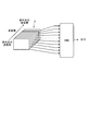
- FIG. 1 is an explanatory diagram showing an outline of an image recognition method according to the first embodiment of the present disclosure.
- the image recognition method uses imaging pixels that receive light in four or more wavelength bands, and for example, as shown in FIG. 1, wavelengths from the infrared light wavelength band to the ultraviolet light wavelength band.
- Image data D is generated by capturing a plurality of images having different bands.
- the composited multispectral image may contain artifacts that do not actually exist.
- the recognition accuracy of the subject may decrease due to the influence of the artifact.
- the image data D of each wavelength band before synthesis does not include artifacts. Therefore, in the image recognition method according to the present disclosure, the subject is recognized from each of the image data D for each wavelength band.
- DNN Deep Neural Network
- DNN is a multi-layered algorithm modeled on a human brain neural network (neural network) designed by machine learning to recognize the characteristics (patterns) of a subject from image data.
- a plurality of image data D having different wavelength bands are input to the DNN.
- the DNN outputs the recognition result of the subject recognized from the image data D of each wavelength band.
- the image data D is input to the DNN for each of the plurality of image data Ds having different wavelength bands that do not include artifacts to recognize the subject, so that the recognition accuracy of the subject can be improved. Can be improved.
- FIG. 2 is a diagram showing a configuration example of an image recognition system according to the first embodiment of the present disclosure.
- the image recognition system 100 according to the first embodiment includes an image sensor 1 which is an example of an image recognition device, and an application processor (hereinafter referred to as AP2).
- AP2 application processor
- the image sensor 1 includes an imaging unit 10, a signal processing unit 13, a recognition unit 14, a data transmission determination unit 15, a selector (hereinafter referred to as SEL16), and a transmission unit 17.
- the imaging unit 10 includes a pixel array 11 and an A / D (Analog / Digital) conversion unit 12.
- the pixel array 11 includes a plurality of image pickup pixels arranged in two dimensions for receiving light of four or more kinds of wavelength bands, and the wavelengths from the infrared light wavelength band to the ultraviolet light wavelength band, for example, depending on the image pickup pixels. Capture multiple images with different bands. Then, the pixel array 11 outputs an analog pixel signal according to the amount of received light from each imaging pixel to the A / D conversion unit 12.
- the A / D conversion unit 12 A / D converts the analog pixel signal input from the pixel array 11 into a digital pixel signal to generate image data, and outputs the image data to the signal processing unit 13.
- the signal processing unit 13 includes a microcomputer having a CPU (Central Processing Unit), a ROM (Read Only Memory), a RAM (Random Access Memory), and various circuits.
- a CPU Central Processing Unit
- ROM Read Only Memory
- RAM Random Access Memory
- the signal processing unit 13 executes predetermined signal processing on the image data input from the A / D conversion unit 12, and outputs the image data of the image after the signal processing to the recognition unit 14 and the SEL 16.
- the flow of processing executed by the signal processing unit 13 will be described.
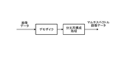
- FIG. 3 is an explanatory diagram of processing executed by the signal processing unit according to the first embodiment of the present disclosure.
- the signal processing unit 13 generates multispectral image data by performing demosaication on the input image data and then performing spectroscopic reconstruction processing, and the recognition unit 14 and Output to SEL16.
- the multispectral image data output to the recognition unit 14 and the SEL 16 is image data of four or more types of each wavelength band, and is a plurality of image data D shown in FIG. 1 before being combined.
- the recognition unit 14 includes a microcomputer having a CPU, ROM, RAM, and various circuits.
- the recognition unit 14 has an object recognition unit 31 that functions by executing an object recognition program stored in the ROM by the CPU using the RAM as a work area, and an object recognition data storage unit 32 provided in the RAM or the ROM. And.
- the object recognition data storage unit 32 stores a plurality of DNNs for each type of object to be recognized.
- the object recognition unit 31 reads out the DNN corresponding to the type of the set recognition target from the object recognition data storage unit 32. Then, the object recognition unit 31 inputs the image data to the DNN, outputs the recognition result of the subject output from the DNN to the data transmission determination unit 15, and outputs the metadata of the recognition result to the SEL 16.
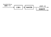
- the recognition unit 14 first normalizes the size and input value of the input multispectral image data according to the size and input value for DNN, and inputs the normalized image data to DNN. And perform object recognition.
- the recognition unit 14 inputs a plurality of (for example, 10) image data having different wavelength bands such as 500 nm, 600 nm, 700 nm, 800 nm, and 900 nm into the DNN. Then, the recognition unit 14 outputs the recognition result of the subject output from the DNN for each image data to the data transmission determination unit 15, and outputs the metadata of the recognition result to the SEL 16.
- a plurality of (for example, 10) image data having different wavelength bands such as 500 nm, 600 nm, 700 nm, 800 nm, and 900 nm into the DNN.
- the recognition unit 14 outputs the recognition result of the subject output from the DNN for each image data to the data transmission determination unit 15, and outputs the metadata of the recognition result to the SEL 16.
- the recognition unit 14 inputs a plurality of image data having different wavelength bands that do not include the artifact to the DNN, and recognizes the subject for each image data, so that the recognition unit 14 is not affected by the artifact and has high accuracy.
- the subject can be recognized.
- the data transmission determination unit 15 outputs a control signal to the SEL 16 for switching the data to be output from the SEL 16 according to the recognition result input from the recognition unit 14.
- the data transmission determination unit 15 outputs a control signal to the SEL 16 to output the image data and the metadata indicating the recognition result to the transmission unit 17.
- the data transmission determination unit 15 outputs a control signal to the SEL 16 to output information (no data) indicating that fact to the transmission unit 17.
- the SEL 16 outputs either a set of image data and metadata or no data to the transmission unit 17 according to the control signal input from the data transmission determination unit 15.
- the transmission unit 17 is a communication I / F (interface) that performs data communication with the AP2, and transmits either a set of image data and metadata input from the SEL16 or no data to the AP2.
- the AP2 includes a microcomputer having a CPU, ROM, RAM, etc. that executes various application programs according to the application of the image recognition system 100, and various circuits.
- the AP2 includes a receiving unit 21, an authentication unit 22, and an authentication data storage unit 23.
- the authentication data storage unit 23 stores an authentication program for authenticating the subject recognized by the image sensor 1, an authentication image data, and the like.
- the receiving unit 21 is a communication I / F that performs data communication with the image sensor 1.
- the receiving unit 21 receives either a set of image data and metadata or no data from the image sensor 1 and outputs it to the authentication unit 22.
- the authentication unit 22 is not activated when no data is input from the receiving unit 21, but is activated when a set of image data and metadata is input.
- the authentication unit 22 is activated, the authentication program is read from the authentication data storage unit 23 and executed, and the subject recognized by the image sensor 1 is authenticated.
- the authentication unit 22 collates the image data with the image data for authentication of the person and identifies who the recognized person is. Perform processing, etc.
- the authentication unit 22 accurately identifies who the recognized person is by identifying the person based on the image data that is not affected by the artifact that the image sensor 1 has recognized with high accuracy that the subject is a person. Can be identified.
- the above-mentioned first embodiment is an example, and various modifications are possible.
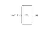
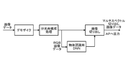
- FIG. 6 is an operation explanatory view of the recognition unit 14 when the signal processing unit according to the first embodiment of the present disclosure is omitted.
- the recognition unit 14 inputs Raw data of the image data output from the imaging unit 10 to the DNN.
- the recognition unit 14 DNN processes the image data in a wavelength band larger than the image data after the spectral reconstruction processing by the signal processing unit 13, which increases the processing load, but recognizes the subject from the larger image data. Therefore, the recognition accuracy of the subject can be further improved.
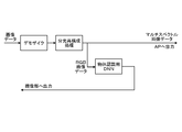
- FIG. 7 is an operation explanatory view of the signal processing unit and the recognition unit according to the second embodiment of the present disclosure.
- the signal processing unit 13 performs demosaic on the image data input from the imaging unit 10 and then performs spectroscopic reconstruction processing to change the wavelength band. Generate multiple different multispectral image data.
- the signal processing unit 13 selectively recognizes RGB image data of the three primary colors of red light (R), green light (G), and blue light (B) from the generated plurality of multispectral image data. Output to 14.
- the recognition unit 14 inputs the RGB image input from the signal processing unit 13 into the object recognition DNN, and recognizes the subject from each of the RGB image data. As a result, the recognition unit 14 can reduce the processing load as compared with the case where the recognition unit 14 recognizes the subject from all the image data generated by the signal processing unit 13.
- the recognition unit 14 may recognize the subject from all the multispectral image data generated by the signal processing unit 13. .. As a result, the recognition unit 14 can recognize the subject more accurately, although the amount of processing increases.
- the recognition unit 14 outputs the multispectral cutout image data obtained by cutting out the portion that recognizes the subject from the plurality of multispectral image data to the AP2 in the subsequent stage.
- the recognition unit 14 cuts out the image data of the portion that recognizes the subject from the image data (raw data) generated by the imaging unit 10 and outputs the image data to the AP2.
- the image sensor according to the second embodiment outputs the image data obtained by cutting out the portion of the captured image data that recognizes the subject to the AP2.
- the AP2 synthesizes a plurality of image data input from the image sensor 1
- only the image data of the portion cut out by the image sensor 1 needs to be combined, so that the processing load can be reduced. Can be done.
- FIG. 8 is an operation explanatory view of the imaging unit, the signal processing unit, and the recognition unit according to the third embodiment of the present disclosure.
- the signal processing unit 13 performs demosaic on the image data input from the imaging unit 10 and then performs spectroscopic reconstruction processing to change the wavelength band. Generate multiple different multispectral image data. After that, the signal processing unit 13 selectively outputs RGB image data from the generated plurality of multispectral image data to the recognition unit 14.
- the recognition unit 14 inputs the RGB image input from the signal processing unit 13 into the object recognition DNN, and recognizes the subject from each of the RGB image data. As a result, the recognition unit 14 can reduce the processing load as compared with the case where the recognition unit 14 recognizes the subject from all the image data generated by the signal processing unit 13.
- the recognition unit 14 may recognize the subject from all the multispectral image data generated by the signal processing unit 13. .. As a result, the recognition unit 14 can recognize the subject more accurately, although the amount of processing increases.
- the recognition unit 14 transmits information indicating the position where the subject is recognized in the RGB image data to the imaging unit 10.
- the imaging unit 10 cuts out a portion corresponding to the portion recognized by the recognition unit 14 from the RGB image data of the previous frame from the image data of the current frame and outputs the portion to the signal processing unit 13.
- the signal processing unit 13 performs demosaic and spectroscopic reconstruction processing on the image data in which the portion recognized as the subject input from the imaging unit 10 is cut out, and outputs the image data to the AP2 in the subsequent stage.
- the signal processing unit 13 can reduce the processing load because the amount of calculation for the demosaic and spectroscopic reconstruction processing is reduced. Further, when synthesizing a plurality of image data input from the image sensor 1, the AP2 only needs to synthesize the image data of the portion cut out by the imaging unit 10, so that the processing load can be reduced.
- the recognition unit 14 recognizes the subject from the image data (Raw data) generated by the image pickup unit 10, and provides information indicating the recognized position of the subject in the image data. Output to the image pickup unit 10.
- the imaging unit 10 cuts out a part corresponding to the part where the subject is recognized from the image data (raw data) of the previous frame by the recognition unit 14 from the image data of the current frame and outputs it to AP2 in the subsequent stage.
- the image sensor according to the third embodiment outputs the image data obtained by cutting out the portion of the captured image data that recognizes the subject to the AP2.
- the AP2 only needs to synthesize the image data of the portion cut out by the imaging unit 10, so that the processing load can be reduced.
- image sensor according to the fourth embodiment Next, the image sensor according to the fourth embodiment will be described.
- the image sensor according to the fourth embodiment is different from the first embodiment in the data output to the AP2 and the operations of the signal processing unit 13 and the recognition unit 14, and the other configurations are the same as those in the first embodiment. Is.
- the image sensor according to the fourth embodiment estimates the sugar content of the fruit to be the subject from a plurality of image data having four or more different wavelength bands, for example, as an example of the nature of the subject, and outputs the estimated sugar content to AP2.
- the signal processing unit 13 first performs demosaication on the image data input from the imaging unit 10, and then performs spectroscopic reconstruction processing to change the wavelength band. Generate multiple different image data.
- the signal processing unit 13 selectively outputs RGB image data out of the generated plurality of image data to the recognition unit 14.
- the recognition unit 14 inputs the RGB image data input from the signal processing unit 13 into the object recognition DNN, and recognizes the subject from each of the RGB image data.
- the recognition unit 14 can reduce the processing load as compared with the case where the recognition unit 14 recognizes the subject from all the image data generated by the signal processing unit 13.
- the recognition unit 14 estimates the effective wavelength according to the subject to be recognized from the RGB image data. For example, the recognition unit 14 estimates a specific wavelength band in which the sugar content of the fruit as the subject can be estimated as an effective wavelength. Then, the recognition unit 14 outputs the estimated effective wavelength to the signal processing unit 13.
- the signal processing unit 13 outputs image data of a specific wavelength band (specific wavelength band image data) corresponding to the effective wavelength input from the recognition unit 14 to the recognition unit 14, as shown in FIG.
- the recognition unit 14 inputs the specific wavelength band image data input from the signal processing unit 13 to the sugar content estimation DNN, and outputs the estimated sugar content of the fruit as the subject output from the sugar content estimation DNN to the AP2.
- the image sensor according to the fourth embodiment estimates the sugar content of the fruit from the image data in the specific wavelength band, the sugar content is estimated from all the multispectral image data generated by the signal processing unit 13. Compared with this, the processing load can be reduced.
- the image sensor according to the fifth embodiment is different from the first embodiment in the pixel array configuration, the imaging operation, and the object recognition operation, and is the same as the first embodiment in other configurations.
- FIG. 11 is an explanatory diagram showing a pixel array according to the fifth embodiment of the present disclosure.
- 12 to 15 are operation explanatory views of the image sensor according to the fifth embodiment of the present disclosure.
- the pixel array 11a includes an image pickup pixel R that receives red light, an image pickup pixel G that receives green light, an image pickup pixel B that receives blue light, and red. It includes an imaging pixel IR that receives external light.
- the imaging lines in which the imaging pixels R and the imaging pixels G are alternately arranged and the imaging lines in which the imaging pixels B and the imaging pixels IR are alternately arranged are alternately 2 It is dimensionally arranged.
- the pixel array 11a can capture RGB images of the three primary colors and IR (Infrared Ray) images.
- a method of capturing an IR image for example, a method of irradiating a subject with infrared light and receiving the infrared light reflected by the subject by an imaging pixel IR for imaging, and a method of capturing infrared light contained in natural light are used.
- the image sensor When adopting the method of irradiating infrared light, the image sensor includes a light emitting unit that irradiates the subject with infrared light.
- the image sensor R, G, B and the image pixel IR are simultaneously exposed, the environment irradiated with infrared light is imaged by the image pixels R, G, B. I can't image a subject of the same color.
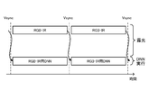
- the image sensor according to the fifth embodiment intermittently irradiates infrared light by the light emitting unit. Then, the imaging unit 10 exposes the imaging pixels R, G, and B during the non-irradiation period of infrared light within one frame period corresponding to one cycle of Vsync (vertical synchronization signal) to obtain the wavelength band of visible light. An image is taken, and the image pickup pixel IR is exposed during the irradiation period of infrared light to take an image in the wavelength band of infrared light.
- Vsync vertical synchronization signal
- the imaging pixels R, G, and B are not irradiated with infrared light during the exposure period, so that the subject of the original color can be imaged without being affected by the infrared light.
- the image pickup pixel IR is irradiated with infrared light during the exposure period, it is possible to reliably capture an IR image.
- the recognition unit 14 executes DNN for RGB during the irradiation period of infrared light, and recognizes the subject from the image data in the wavelength band of visible light. Further, the recognition unit 14 executes the IR DNN during the non-irradiation period of the infrared light, and recognizes the subject from the image data in the wavelength band of the infrared light.
- the recognition unit 14 inputs the image data captured by the imaging pixels R, G, and B into the RGB DNN, and recognizes the subject from the image data in the wavelength band of visible light. .. Further, the recognition unit 14 inputs the image data captured by the imaging pixel IR into the IR DNN and recognizes the subject from the image data in the wavelength band of infrared light. As a result, the image sensor can capture the RGB image and the IR image within one frame period and recognize the subject from both the RGB image and the IR image.
- the image pickup unit 10 receives the image pickup pixel R, G, B and the imaging pixel IR are exposed at the same time.
- the imaging unit 10 can simultaneously capture an RGB image in the wavelength band of visible light and an IR image in the wavelength band of infrared light. Then, the recognition unit 14 executes the RGB-IR DNN within one frame period, and within one frame period, the image data of the visible light wavelength band and the image data of the infrared light wavelength band of the previous frame. Recognize the subject from.
- the recognition unit 14 simultaneously inputs the image data captured by the imaging pixels R, G, and B and the image data captured by the imaging pixel IR into the RGB-IR DNN. ..
- the recognition unit 14 can simultaneously recognize the subject from the image data in the wavelength band of visible light and the image data in the wavelength band of infrared light.
- the image sensor 1 which is an example of the image recognition device, has an image pickup unit 10 and a recognition unit 14.
- the imaging unit 10 uses imaging pixels that receive light in four or more wavelength bands to capture a plurality of images having different wavelength bands to generate image data.
- the recognition unit recognizes the subject from each of the plurality of image data for each wavelength band. As a result, the image sensor can improve the recognition accuracy of the subject by recognizing the subject without being affected by the artifact.
- the recognition unit 14 cuts out the image data of the portion that recognizes the subject from the image data generated by the imaging unit 10 and outputs the image data to the subsequent device.
- the image sensor 1 can reduce the processing load of the device in the subsequent stage.
- the imaging unit 10 cuts out a portion corresponding to the portion recognized by the recognition unit from the image data of the previous frame from the image data of the current frame and outputs the portion.
- the image sensor 1 can reduce the processing load of the device in the subsequent stage.
- the recognition unit 14 recognizes the subject from the image data of the wavelength bands of the three primary colors among the image data generated by the image pickup unit 10. As a result, the image sensor 1 can reduce the processing load of the recognition unit 14.
- the recognition unit 14 estimates the property of the subject based on the image data of the specific wavelength band corresponding to the subject to be recognized from the image data. As a result, the image sensor 1 can estimate the nature of the subject while reducing the processing load of the recognition unit 14.
- the image sensor 1 which is an example of the image recognition device has a signal processing unit 13 which performs demosaic and spectroscopic reconstruction processing on the image data.
- the recognition unit 14 recognizes the subject from the image data after the demosaic and spectroscopic reconstruction processing.
- the image sensor 1 can recognize the subject from the image data from which the noise component has been removed by the signal processing unit 13, for example, so that the recognition accuracy of the subject can be improved.
- the recognition unit 14 recognizes the subject from the image data (Raw data) input from the image pickup unit 10.
- the image sensor 1 can improve the recognition accuracy of the subject by recognizing the subject from the Raw data having a larger amount of data than the image data generated by the signal processing unit 13.
- the image sensor which is an example of the image recognition device, has a light emitting unit that intermittently irradiates the subject with infrared light.
- the imaging unit 10 captures an image of the visible light wavelength band during the infrared light non-irradiation period, and captures an image of the infrared light wavelength band during the infrared light irradiation period.
- the recognition unit 14 recognizes the subject from the image data in the wavelength band of visible light during the irradiation period, and recognizes the subject from the image data in the wavelength band of infrared light during the non-irradiation period.
- the image sensor can accurately recognize the subject from the image data of the visible light wavelength band to be imaged without being affected by the infrared light, and further captures the image of the infrared light wavelength band.
- the subject can also be recognized from the image data of infrared light.
- the imaging unit 10 simultaneously captures an image in the wavelength band of visible light and an image in the wavelength band of infrared light.
- the recognition unit 14 captures the image data of the visible light wavelength band and the image of the infrared light wavelength band in the previous frame during one frame period in which the image of the visible light wavelength band and the image of the infrared light wavelength band are captured. Recognize the subject from the data.
- the image sensor can simultaneously capture an image in the wavelength band of visible light and an image in the wavelength band of infrared light within one frame period, and can recognize the subject from each of the two images.
- the image recognition method uses image pickup pixels that receive light of four or more kinds of wavelength bands, images a plurality of images having different wavelength bands to generate image data, and generates image data for each wavelength band. Recognize the subject from each. According to such an image recognition method, the recognition accuracy of the subject can be improved by recognizing the subject without being affected by the artifact.
- the present technology can also have the following configurations.
- An imaging unit that uses imaging pixels that receive light in four or more wavelength bands to capture multiple images with different wavelength bands and generate image data.
- An image recognition device having a recognition unit that recognizes a subject from each of a plurality of the image data for each wavelength band.
- the recognition unit The image recognition device according to (1), wherein the image data of the portion that recognizes the subject is cut out from the image data generated by the imaging unit and output to the subsequent device.
- (3) The imaging unit The image recognition device according to (1) above, wherein a portion corresponding to a portion recognized by the subject from the image data of the previous frame by the recognition unit is cut out from the image data of the current frame and output.
- the recognition unit The image recognition device according to any one of (1) to (3), which recognizes the subject from image data in wavelength bands of three primary colors among the image data generated by the imaging unit. (5) The recognition unit The image recognition device according to any one of (1) to (4) above, which estimates the properties of the subject based on the image data of a specific wavelength band corresponding to the subject to be recognized from the image data. (6) It has a signal processing unit that performs demosaic and spectroscopic reconstruction processing on the image data. The recognition unit The image recognition device according to any one of (1) to (5) above, which recognizes the subject from the image data after the demosaic and spectroscopic reconstruction processing.
- the recognition unit The image recognition device according to any one of (1) to (5), which recognizes the subject from the image data input from the image pickup unit. (8) It has a light emitting part that intermittently irradiates the subject with infrared light.
- the imaging unit An image of a visible light wavelength band is imaged during the infrared light non-irradiation period, and an image of an infrared light wavelength band is imaged during the infrared light irradiation period.
- the recognition unit Any of the above (1) to (7), which recognizes the subject from the image data of the wavelength band of visible light during the irradiation period and recognizes the subject from the image data of the wavelength band of infrared light during the non-irradiation period.
- the image recognition device described in one. (9) The imaging unit Images in the wavelength band of visible light and images in the wavelength band of infrared light are simultaneously captured. The recognition unit During one frame period in which the image of the visible light wavelength band and the image of the infrared light wavelength band are captured, the subject is taken from the image data of the visible light wavelength band and the image data of the infrared light wavelength band in the previous frame. Recognizing The image recognition device according to any one of (1) to (7) above. (10) Using image pickup pixels that receive light in four or more wavelength bands, multiple images with different wavelength bands are imaged to generate image data. An image recognition method for recognizing a subject from each of a plurality of the image data for each wavelength band.
- Image recognition system 100 Image recognition system 1 Image sensor 10 Imaging unit 11, 11a Pixel array 12 A / D conversion unit 13 Signal processing unit 14 Recognition unit 15 Data transmission judgment unit 16 SEL 17 Transmitter 2 AP 21 Receiver 22 Authentication unit 23 Authentication data storage unit 31 Object recognition unit 32 Object recognition data storage unit
Landscapes
- Engineering & Computer Science (AREA)
- Theoretical Computer Science (AREA)
- General Physics & Mathematics (AREA)
- Physics & Mathematics (AREA)
- Computer Vision & Pattern Recognition (AREA)
- Multimedia (AREA)
- Evolutionary Computation (AREA)
- Artificial Intelligence (AREA)
- Medical Informatics (AREA)
- Software Systems (AREA)
- General Health & Medical Sciences (AREA)
- Databases & Information Systems (AREA)
- Computing Systems (AREA)
- Health & Medical Sciences (AREA)
- Color Television Image Signal Generators (AREA)
Abstract
被写体の認識精度を向上させることができる画像認識装置および画像認識方法を提供する。本開示に係る画像認識装置(イメージセンサ1)は、撮像部(10)と、認識部(14)とを有する。撮像部(10)は、4種類以上の波長帯の光を受光する撮像画素(R,G,B,IR)を使用し、波長帯の異なる複数の画像を撮像して画像データを生成する。認識部(14)は、前記波長帯毎に複数の前記画像データのそれぞれから被写体を認識する。
Description
本開示は、画像認識装置および画像認識方法に関する。
4種類以上の波長帯の光を受光する撮像画素を使用して波長帯が異なる複数の画像を撮像し、撮像画像の波長ごとのデータを合成することによって、マルチスペクトル画像を生成する装置がある(例えば、特許文献1参照)。マルチスペクトル画像は、例えば、肉眼では認識し難い被写体の認識や被写体の性質の推定等に使用される。
しかしながら、上記の従来技術では、被写体の認識精度が低下することがある。そこで、本開示では、被写体の認識精度を向上させることができる画像認識装置および画像認識方法を提案する。
本開示に係る画像認識装置は、撮像部と、認識部とを有する。撮像部は、4種類以上の波長帯の光を受光する撮像画素を使用し、波長帯の異なる複数の画像を撮像して画像データを生成する。認識部は、前記波長帯毎に複数の前記画像データのそれぞれから被写体を認識する。
以下に、本開示の実施形態について図面に基づいて詳細に説明する。なお、以下の各実施形態において、同一の部位には同一の符号を付することにより重複する説明を省略する。
[1.第1の実施形態]
[1-1.第1の実施形態に係る画像認識方法の概要]
まず、本開示に係る画像認識方法の概要について説明する。図1は、本開示の第1の実施形態に係る画像認識方法の概要を示す説明図である。
[1-1.第1の実施形態に係る画像認識方法の概要]
まず、本開示に係る画像認識方法の概要について説明する。図1は、本開示の第1の実施形態に係る画像認識方法の概要を示す説明図である。
本開示に係る画像認識方法では、4種類以上の波長帯の光を受光する撮像画素を使用し、例えば、図1に示すように、赤外光の波長帯から紫外光の波長帯までの波長帯が異なる複数の画像を撮像して画像データDを生成する。
かかる波長帯が異なる複数の画像データDを合成することによって、マルチスペクトル画像を生成することが可能である。しかしながら、合成後のマルチスペクトル画像には、実際には存在しないアーチファクトが写り込むことがある。
このため、合成後のマルチスペクトル画像から被写体を認識した場合、アーチファクトの影響によって、被写体の認識精度が低下することがある。ただし、合成前の各波長帯の画像データDには、アーチファクトが含まれることがない。そこで、本開示に係る画像認識方法では、波長帯毎に各画像データDのそれぞれから被写体を認識する。
ここで、画像データDから被写体を認識する方法の一例として、DNN(Deep Neural Network)を用いる画像認識方法がある。DNNは、画像データから被写体の特徴(パターン)を認識するように機械学習によって設計された人間の脳神経回路(ニューラルネットワーク)をモデルとした多階層構造のアルゴリズムである。
本開示に係る画像認識方法では、波長帯が異なる複数の画像データDをDNNへ入力する。これにより、DNNからは、各波長帯の画像データDから認識された被写体の認識結果が出力される。
このように、本開示に係る画像認識方法では、アーチファクトが含まれない波長帯が異なる複数の画像データD毎に、画像データDをDNNへ入力して被写体を認識するので、被写体の認識精度を向上させることができる。
[1-2.第1の実施形態に係る画像認識システムの構成]
次に、図2を参照し、第1の実施形態に係る画像認識システムの構成について説明する。図2は、本開示の第1の実施形態に係る画像認識システムの構成例を示す図である。図2に示すように、第1の実施形態に係る画像認識システム100は、画像認識装置の一例であるイメージセンサ1と、アプリケーションプロセッサ(以下、AP2と記載する)とを有する。
次に、図2を参照し、第1の実施形態に係る画像認識システムの構成について説明する。図2は、本開示の第1の実施形態に係る画像認識システムの構成例を示す図である。図2に示すように、第1の実施形態に係る画像認識システム100は、画像認識装置の一例であるイメージセンサ1と、アプリケーションプロセッサ(以下、AP2と記載する)とを有する。
イメージセンサ1は、撮像部10と、信号処理部13と、認識部14と、データ送信判断部15と、セレクタ(以下、SEL16と記載する)と、送信部17とを備える。撮像部10は、画素アレイ11と、A/D(Analog/Digital)変換部12とを備える。
画素アレイ11は、4種類以上の波長帯の光を受光する2次元に配列された複数の撮像画素を備え、撮像画素によって、例えば、赤外光の波長帯から紫外光の波長帯までの波長帯が異なる複数の画像を撮像する。そして、画素アレイ11は、各撮像画素からA/D変換部12へ受光量に応じたアナログの画素信号を出力する。A/D変換部12は、画素アレイ11から入力されるアナログの画素信号をデジタルの画素信号にA/D変換して画像データを生成し、画像データを信号処理部13へ出力する。
信号処理部13は、CPU(Central Processing Unit)、ROM(Read Only Memory)、RAM(Random Access Memory)などを有するマイクロコンピュータや各種の回路を含む。
信号処理部13は、A/D変換部12から入力される画像データに対して所定の信号処理を実行し、信号処理後の画像の画像データを認識部14と、SEL16へ出力する。ここで、図3を参照し、信号処理部13が実行する処理の流れについて説明する。
図3は、本開示の第1の実施形態に係る信号処理部が実行する処理の説明図である。図3に示すように、信号処理部13は、入力される画像データに対して、デモザイクを行い、その後、分光再構成処理を行うことによって、マルチスペクトル画像データを生成し、認識部14と、SEL16へ出力する。
ここで、認識部14およびSEL16へ出力されるマルチスペクトル画像データは、4種類以上の各波長帯の画像データであり、合成される前の図1に示した複数の画像データDである。
図2へ戻り、認識部14は、CPU、ROM、RAMなどを有するマイクロコンピュータや各種の回路を含む。認識部14は、CPUがROMに記憶された物体認識プログラムを、RAMを作業領域として使用して実行することにより機能する物体認識部31と、RAMまたはROMに設けられる物体認識用データ記憶部32とを備える。物体認識用データ記憶部32には、認識対象となる物体の種類別に複数のDNNが記憶されている。
物体認識部31は、設定される認識対象の種類に応じたDNNを物体認識用データ記憶部32から読み出す。そして、物体認識部31は、画像データをDNNへ入力してDNNから出力される被写体の認識結果をデータ送信判断部15へ出力し、認識結果のメタデータをSEL16へ出力する。
ここで、図4および図5を参照し、認識部14が行う処理の流れについて説明する。図4および図5は、本開示の第1の実施形態に係る認識部が実行する処理の説明図である。図4に示すように、認識部14は、まず、入力されるマルチスペクトル画像データのサイズおよび入力値をDNN用のサイズおよび入力値に合わせて正規化し、正規化後の画像データをDNNへ入力して物体認識を行う。
このとき、認識部14は、図5に示すように、例えば、500nm、600nm、700nm、800nm、900nm等の波長帯が異なる複数(例えば、10)の画像データをDNNへ入力する。そして、認識部14は、DNNから各画像データ毎に出力される被写体の認識結果をデータ送信判断部15へ出力し、認識結果のメタデータをSEL16へ出力する。
このように、認識部14は、アーチファクトを含まない波長帯が異なる複数の画像データをDNNへ入力し、各画像データ毎に被写体を認識するので、アーチファクトの影響を受けることがなく、高精度に被写体を認識することができる。
図2へ戻り、データ送信判断部15は、認識部14から入力される認識結果に応じてSEL16から出力させるデータを切替える制御信号をSEL16へ出力する。データ送信判断部15は、認識部14によって被写体が認識された場合には、画像データと、認識結果を示すメタデータとを送信部17へ出力させる制御信号をSEL16へ出力する。
また、データ送信判断部15は、認識部14によって被写体が認識されなかった場合、その旨を示す情報(ノーデータ)を送信部17へ出力させる制御信号をSEL16へ出力する。SEL16は、データ送信判断部15から入力される制御信号に応じて、画像データおよびメタデータのセット、または、ノーデータのいずれかを送信部17へ出力する。
送信部17は、AP2との間でデータ通信を行う通信I/F(インターフェース)であり、SEL16から入力される画像データおよびメタデータのセット、または、ノーデータのいずれかをAP2へ送信する。
AP2は、画像認識システム100の用途に応じた各種アプリケーションプログラムを実行するCPU、ROM、RAMなどを有するマイクロコンピュータや各種の回路を含む。AP2は、受信部21と、認証部22と、認証用データ記憶部23とを備える。
認証用データ記憶部23には、イメージセンサ1によって認識された被写体を認証するための認証用プログラムおよび認証用画像データ等が記憶されている。受信部21は、イメージセンサ1との間でデータ通信を行う通信I/Fである。受信部21は、イメージセンサ1から画像データおよびメタデータのセット、または、ノーデータのいずれかを受信して認証部22へ出力する。
認証部22は、受信部21からノーデータが入力される場合には起動せず、画像データおよびメタデータのセットが入力された場合に起動する。認証部22は、起動すると認証用データ記憶部23から認証用プログラムを読み出して実行し、イメージセンサ1によって認識された被写体を認証する。
例えば、認証部22は、被写体が人であることを示すメタデータと画像データのセットが入力される場合、画像データと人の認証用画像データとを照合し、認識された人が誰かを特定する処理等を行う。
このとき、認証部22は、イメージセンサ1によって被写体が人であると高精度に認識されたアーチファクトの影響がない画像データに基づいて人を特定することにより、認識された人が誰かを的確に特定することができる。なお、上記した第1の実施形態は、一例であり、種々の変形が可能である。
例えば、イメージセンサ1は、図2に示す信号処理部13を省略することもできる。図6は、本開示の第1の実施形態に係る信号処理部を省略した場合の認識部14の動作説明図である。図6に示すように、認識部14は、信号処理部13が省略される場合、撮像部10から出力される画像データのRawデータをDNNへ入力する。
この場合、認識部14は、信号処理部13による分光再構成処理後の画像データよりも多い波長帯の画像データをDNN処理することになり処理負荷が増すが、より多い画像データから被写体を認識するため、被写体の認識精度をさらに向上させることができる。
[2.第2の実施形態に係るイメージセンサ]
次に、第2の実施形態に係るイメージセンサについて説明する。第2の実施形態に係るイメージセンサは、信号処理部13および認識部14の動作が第1の実施形態とは異なり、他の構成については第1の実施形態と同様である。
次に、第2の実施形態に係るイメージセンサについて説明する。第2の実施形態に係るイメージセンサは、信号処理部13および認識部14の動作が第1の実施形態とは異なり、他の構成については第1の実施形態と同様である。
このため、ここでは、第2の実施形態に係る信号処理部13および認識部14の動作について説明し、その他の構成については重複する説明を省略する。図7は、本開示の第2の実施形態に係る信号処理部および認識部の動作説明図である。
図7に示すように、第2の実施形態では、信号処理部13は、撮像部10から入力される画像データに対してデモザイクを行った後、分光再構成処理を行うことで、波長帯が異なる複数のマルチスペクトル画像データを生成する。
その後、信号処理部13は、生成した複数のマルチスペクトル画像データのうち、赤色光(R)、緑色光(G)、および青色光(B)の3原色のRGB画像データを選択的に認識部14へ出力する。
認識部14は、信号処理部13から入力されるRGB画像を物体認識用DNNへ入力し、RGB画像データのそれぞれから被写体を認識する。これにより、認識部14は、信号処理部13によって生成される全画像データから被写体を認識する場合に比べて処理負荷を低減することができる。
なお、ここでは、認識部14がRGB画像データから被写体を認識する場合について説明したが、認識部14は、信号処理部13によって生成される全てのマルチスペクトル画像データから被写体を認識してもよい。これにより、認識部14は、処理量が増加するが、その分、より正確に被写体を認識することができる。
その後、認識部14は、複数のマルチスペクトル画像データから被写体を認識した部分を切り出したマルチスペクトル切り出し画像データを後段のAP2へ出力する。なお、認識部14は、信号処理部13が省略される場合には、撮像部10によって生成される画像データ(Rawデータ)から被写体を認識した部分の画像データを切り出してAP2へ出力する。
このように、第2の実施形態に係るイメージセンサは、撮像した画像データのうち、被写体を認識した部分を切り出した画像データをAP2へ出力する。これにより、例えば、AP2は、イメージセンサ1から入力される複数の画像データを合成する場合に、イメージセンサ1によって切り出された部分の画像データだけを合成すればよいため、処理負荷を低減することができる。
[3.第3の実施形態に係るイメージセンサ]
次に、第3の実施形態に係るイメージセンサについて説明する。第3の実施形態に係るイメージセンサは、撮像部10、信号処理部13、および認識部14の動作が第1の実施形態とは異なり、他の構成については第1の実施形態と同様である。
次に、第3の実施形態に係るイメージセンサについて説明する。第3の実施形態に係るイメージセンサは、撮像部10、信号処理部13、および認識部14の動作が第1の実施形態とは異なり、他の構成については第1の実施形態と同様である。
このため、ここでは、第3の実施形態に係る撮像部10、信号処理部13、および認識部14の動作について説明し、その他の構成については重複する説明を省略する。図8は、本開示の第3の実施形態に係る撮像部、信号処理部、および認識部の動作説明図である。
図8に示すように、第3の実施形態では、信号処理部13は、撮像部10から入力される画像データに対してデモザイクを行った後、分光再構成処理を行うことで、波長帯が異なる複数のマルチスペクトル画像データを生成する。その後、信号処理部13は、生成した複数のマルチスペクトル画像データのうち、RGB画像データを選択的に認識部14へ出力する。
認識部14は、信号処理部13から入力されるRGB画像を物体認識用DNNへ入力し、RGB画像データのそれぞれから被写体を認識する。これにより、認識部14は、信号処理部13によって生成される全画像データから被写体を認識する場合に比べて処理負荷を低減することができる。
なお、ここでは、認識部14がRGB画像データから被写体を認識する場合について説明したが、認識部14は、信号処理部13によって生成される全てのマルチスペクトル画像データから被写体を認識してもよい。これにより、認識部14は、処理量が増加するが、その分、より正確に被写体を認識することができる。
その後、認識部14は、RGB画像データにおける被写体を認識した位置を示す情報を撮像部10へする。撮像部10は、認識部14によって前フレームのRGB画像データから被写体が認識された部分と対応する部分を今フレームの画像データから切り出して信号処理部13へ出力する。信号処理部13は、撮像部10から入力される被写体が認識された部分が切り出された画像データに対して、デモザイクおよび分光再構成処理を行い、後段のAP2へ出力する。
これにより、信号処理部13は、デモザイクおよび分光再構成処理の計算量が減少するので、処理負荷を低減することができる。また、AP2は、イメージセンサ1から入力される複数の画像データを合成する場合に、撮像部10によって切り出された部分の画像データだけを合成すればよいため、処理負荷を低減することができる。
なお、認識部14は、信号処理部13が省略される場合には、撮像部10によって生成される画像データ(Rawデータ)から被写体を認識し、画像データにおける被写体を認識した位置を示す情報を撮像部10へ出力する。
撮像部10は、認識部14によって前フレームの画像データ(Rawデータ)から被写体が認識された部分と対応する部分を今フレームの画像データから切り出して後段のAP2へ出力する。
このように、第3の実施形態に係るイメージセンサは、撮像した画像データのうち、被写体を認識した部分を切り出した画像データをAP2へ出力する。これにより、AP2は、信号処理部13が省略される場合も、撮像部10によって切り出された部分の画像データだけを合成すればよいため、処理負荷を低減することができる。
[4.第4の実施形態に係るイメージセンサ]
次に、第4の実施形態に係るイメージセンサについて説明する。第4の実施形態に係るイメージセンサは、AP2へ出力するデータと、信号処理部13および認識部14の動作が第1の実施形態とは異なり、他の構成については第1の実施形態と同様である。
次に、第4の実施形態に係るイメージセンサについて説明する。第4の実施形態に係るイメージセンサは、AP2へ出力するデータと、信号処理部13および認識部14の動作が第1の実施形態とは異なり、他の構成については第1の実施形態と同様である。
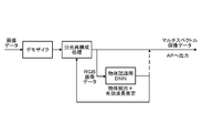
このため、ここでは、第4の実施形態に係る信号処理部13および認識部14の動作について説明し、その他の構成については重複する説明を省略する。図9および図10は、本開示の第4の実施形態に係る信号処理部および認識部の動作説明図である。
第4の実施形態に係るイメージセンサは、4種類以上の波長帯が異なる複数の画像データから、例えば、被写体の性質の一例として、被写体となる果物の糖度を推定し、推定糖度をAP2へ出力する。具体的には、図9に示すように、信号処理部13は、まず、撮像部10から入力される画像データに対してデモザイクを行った後、分光再構成処理を行うことで、波長帯が異なる複数の画像データを生成する。
その後、信号処理部13は、生成した複数の画像データのうち、RGB画像データを選択的に認識部14へ出力する。認識部14は、信号処理部13から入力されるRGB画像データを物体認識用DNNへ入力し、RGB画像データのそれぞれから被写体を認識する。これにより、認識部14は、信号処理部13によって生成される全画像データから被写体を認識する場合に比べて処理負荷を低減することができる。
さらに、認識部14は、RGB画像データから認識する被写体に応じた有効波長を推定する。例えば、認識部14は、被写体となった果物の糖度を推定可能な特定波長帯を有効波長として推定する。そして、認識部14は、推定した有効波長を信号処理部13へ出力する。
信号処理部13は、次フレーム以降、図10に示すように、認識部14から入力される有効波長に対応する特定波長帯の画像データ(特定波長帯画像データ)を認識部14へ出力する。認識部14は、信号処理部13から入力される特定波長帯画像データを糖度推定用DNNへ入力し、糖度推定用DNNから出力される被写体となった果物の推定糖度をAP2へ出力する。
このように、第4の実施形態に係るイメージセンサは、特定波長帯画像データから果物の糖度を推定するので、信号処理部13によって生成される全てのマルチスペクトル画像データから糖度を推定する場合に比べて処理負荷を低減することができる。
[5.第5の実施形態に係るイメージセンサ]
次に、第5の実施形態に係るイメージセンサについて説明する。第5の実施形態に係るイメージセンサは、画素アレイの構成、撮像動作、および物体認識動作が第1の実施形態とは異なり、他の構成については第1の実施形態と同様である。
次に、第5の実施形態に係るイメージセンサについて説明する。第5の実施形態に係るイメージセンサは、画素アレイの構成、撮像動作、および物体認識動作が第1の実施形態とは異なり、他の構成については第1の実施形態と同様である。
このため、ここでは、第5の実施形態に係る画素アレイの構成、撮像動作、および物体認識動作について説明し、その他の構成については重複する説明を省略する。図11は、本開示の第5の実施形態に係る画素アレイを示す説明図である。図12~図15は、本開示の第5の実施形態に係るイメージセンサの動作説明図である。
図11に示すように、第5の実施形態に係る画素アレイ11aは、赤色光を受光する撮像画素Rと、緑色光を受光する撮像画素Gと、青色光を受光する撮像画素Bと、赤外光を受光する撮像画素IRとを備える。
図11に示す例では、画素アレイ11aは、撮像画素Rおよび撮像画素Gが交互に配置される撮像ラインと、撮像画素Bと撮像画素IRとが交互に配置される撮像ラインとが交互に2次元配置されている。
かかる画素アレイ11aは、3原色のRGB画像と、IR(Infrared Ray)画像とを撮像することが可能である。IR画像を撮像する方法として、例えば、被写体に対して赤外光を照射し、被写体によって反射される赤外光を撮像画素IRによって受光して撮像する方法と、自然光に含まれる赤外光を撮像画素IRによって受光して撮像する方法とがある。
赤外光を照射する方法を採用する場合、イメージセンサは、被写体へ赤外光を照射する発光部を備える。かかる構成の場合、イメージセンサは、撮像画素R、G、Bと、撮像画素IRとを同時に露光すると、赤外光が照射された環境が撮像画素R、G、Bによって撮像されるので、本来の色の被写体を撮像することができない。
そこで、図12に示すように、第5実施形態に係るイメージセンサは、発光部によって赤外光を間欠的に照射させる。そして、撮像部10は、Vsync(垂直同期信号)の1周期に相当する1フレーム期間内で、赤外光の非照射期間に撮像画素R、G、Bを露光して可視光の波長帯の画像を撮像し、赤外光の照射期間に撮像画素IRを露光して赤外光の波長帯の画像を撮像する。
これにより、撮像画素R、G、Bは、露光期間に赤外光が照射されないので、赤外光の影響を受けることなく、本来の色の被写体を撮像することができる。一方、撮像画素IRは、露光期間に赤外光が照射されるので、確実にIR画像を撮像することができる。
また、認識部14は、赤外光の照射期間に、RGB用DNNを実行して、可視光の波長帯の画像データから被写体を認識する。また、認識部14は、赤外光の非照射期間に、IR用DNNを実行して、赤外光の波長帯の画像データから被写体を認識する。
このとき、図13に示すように、認識部14は、撮像画素R、G、Bによって撮像された画像データをRGB用DNNへ入力して、可視光の波長帯の画像データから被写体を認識する。また、認識部14は、撮像画素IRによって撮像された画像データをIR用DNNへ入力して、赤外光の波長帯の画像データから被写体を認識する。これにより、イメージセンサは、1フレーム期間内に、RGB画像とIR画像とを撮像し、RGB画像およびIR画像の双方から被写体を認識することができる。
また、図14に示すように、第5実施形態に係るイメージセンサは、自然光に含まれる赤外光を撮像画素IRによって受光して撮像する方法を採用する場合、撮像部10が撮像画素R、G、Bおよび撮像画素IRを同時に露光する。
これにより、撮像部10は、可視光の波長帯のRGB画像および赤外光の波長帯のIR画像を同時に撮像することができる。そして、認識部14は、1フレーム期間内に、RGB-IR用DNNを実行して、1フレーム期間内に、前フレームの可視光の波長帯の画像データおよび赤外光の波長帯の画像データから被写体を認識する。
このとき、図15に示すように、認識部14は、撮像画素R、G、Bによって撮像された画像データと、撮像画素IRによって撮像された画像データとを同時にRGB-IR用DNNへ入力する。これにより、認識部14は、可視光の波長帯の画像データと、赤外光の波長帯の画像データとから同時に被写体を認識することができる。
[6.効果]
画像認識装置の一例であるイメージセンサ1は、撮像部10と、認識部14とを有する。撮像部10は、4種類以上の波長帯の光を受光する撮像画素を使用し、波長帯の異なる複数の画像を撮像して画像データを生成する。認識部は、波長帯毎に複数の画像データのそれぞれから被写体を認識する。これにより、イメージセンサは、アーチファクトの影響を受けることなく被写体を認識することで、被写体の認識精度を向上させることができる。
画像認識装置の一例であるイメージセンサ1は、撮像部10と、認識部14とを有する。撮像部10は、4種類以上の波長帯の光を受光する撮像画素を使用し、波長帯の異なる複数の画像を撮像して画像データを生成する。認識部は、波長帯毎に複数の画像データのそれぞれから被写体を認識する。これにより、イメージセンサは、アーチファクトの影響を受けることなく被写体を認識することで、被写体の認識精度を向上させることができる。
また、認識部14は、撮像部10によって生成される画像データから被写体を認識した部分の画像データを切り出して後段の装置へ出力する。これにより、イメージセンサ1は、後段の装置の処理負荷を低減することができる。
また、撮像部10は、認識部によって前フレームの画像データから被写体が認識された部分と対応する部分を今フレームの画像データから切り出して出力する。これにより、イメージセンサ1は、後段の装置の処理負荷を低減することができる。
また、認識部14は、撮像部10によって生成された画像データのうち、3原色の波長帯の画像データから被写体を認識する。これにより、イメージセンサ1は、認識部14の処理負荷を低減することができる。
また、認識部14は、画像データから認識する被写体に応じた特定波長帯の画像データに基づいて、被写体の性質を推定する。これにより、イメージセンサ1は、認識部14の処理負荷を低減しつつ、被写体の性質を推定することができる。
また、画像認識装置の一例であるイメージセンサ1は、画像データに対してデモザイクおよび分光再構成処理を行う信号処理部13を有する。認識部14は、デモザイクおよび分光再構成処理後の画像データから被写体を認識する。これにより、イメージセンサ1は、例えば、信号処理部13によってノイズ成分が除去された画像データから被写体を認識することができるため、被写体の認識精度を向上させることができる。
また、認識部14は、撮像部10から入力される画像データ(Rawデータ)から被写体を認識する。これにより、イメージセンサ1は、信号処理部13により生成される画像データよりもデータ量が多いRawデータから被写体を認識することで、被写体の認識精度を向上させることができる。
また、画像認識装置の一例であるイメージセンサは、被写体に対して間欠的に赤外光を照射する発光部を有する。撮像部10は、赤外光の非照射期間に可視光の波長帯の画像を撮像し、赤外光の照射期間に赤外光の波長帯の画像を撮像する。認識部14は、照射期間に可視光の波長帯の画像データから被写体を認識し、非照射期間に赤外光の波長帯の画像データから被写体を認識する。これにより、イメージセンサは、赤外光の影響を受けることなく撮像する可視光の波長帯の画像データから正確に被写体を認識することができ、さらに、赤外光の波長帯の画像を撮像し、赤外光の画像データから被写体を認識することもできる。
また、撮像部10は、可視光の波長帯の画像および赤外光の波長帯の画像を同時に撮像する。認識部14は、可視光の波長帯の画像および赤外光の波長帯の画像が撮像される1フレーム期間に、前フレームの可視光の波長帯の画像データおよび赤外光の波長帯の画像データから被写体を認識する。これにより、イメージセンサは、1フレーム期間内に、可視光の波長帯の画像および赤外光の波長帯の画像を同時撮像し、両画像のそれぞれから被写体を認識することができる。
また、画像認識方法は、4種類以上の波長帯の光を受光する撮像画素を使用し、波長帯の異なる複数の画像を撮像して画像データを生成し、波長帯毎に複数の画像データのそれぞれから被写体を認識する。かかる画像認識方法によれば、アーチファクトの影響を受けることなく被写体を認識することで、被写体の認識精度を向上させることができる。
なお、本明細書に記載された効果はあくまで例示であって限定されるものでは無く、また他の効果があってもよい。
なお、本技術は以下のような構成も取ることができる。
(1)
4種類以上の波長帯の光を受光する撮像画素を使用し、波長帯の異なる複数の画像を撮像して画像データを生成する撮像部と、
前記波長帯毎に複数の前記画像データのそれぞれから被写体を認識する認識部と
を有する画像認識装置。
(2)
前記認識部は、
前記撮像部によって生成される画像データから前記被写体を認識した部分の画像データを切り出して後段の装置へ出力する
前記(1)に記載の画像認識装置。
(3)
前記撮像部は、
前記認識部によって前フレームの画像データから前記被写体が認識された部分と対応する部分を今フレームの画像データから切り出して出力する
前記(1)に記載の画像認識装置。
(4)
前記認識部は、
前記撮像部によって生成された画像データのうち、3原色の波長帯の画像データから前記被写体を認識する
前記(1)~(3)のいずれか一つに記載の画像認識装置。
(5)
前記認識部は、
前記画像データから認識する被写体に応じた特定波長帯の画像データに基づいて、前記被写体の性質を推定する
前記(1)~(4)のいずれか一つに記載の画像認識装置。
(6)
前記画像データに対してデモザイクおよび分光再構成処理を行う信号処理部
を有し、
前記認識部は、
デモザイクおよび分光再構成処理後の画像データから前記被写体を認識する
前記(1)~(5)のいずれか一つに記載の画像認識装置。
(7)
前記認識部は、
前記撮像部から入力される前記画像データから前記被写体を認識する
前記(1)~(5)のいずれか一つに記載の画像認識装置。
(8)
被写体に対して間欠的に赤外光を照射する発光部
を有し、
前記撮像部は、
前記赤外光の非照射期間に可視光の波長帯の画像を撮像し、前記赤外光の照射期間に赤外光の波長帯の画像を撮像し、
前記認識部は、
前記照射期間に可視光の波長帯の画像データから前記被写体を認識し、前記非照射期間に赤外光の波長帯の画像データから前記被写体を認識する
前記(1)~(7)のいずれか一つに記載の画像認識装置。
(9)
前記撮像部は、
可視光の波長帯の画像および赤外光の波長帯の画像を同時に撮像し、
前記認識部は、
可視光の波長帯の画像および赤外光の波長帯の画像が撮像される1フレーム期間に、前フレームの可視光の波長帯の画像データおよび赤外光の波長帯の画像データから前記被写体を認識する
前記(1)~(7)のいずれか一つに記載の画像認識装置。
(10)
4種類以上の波長帯の光を受光する撮像画素を使用し、波長帯の異なる複数の画像を撮像して画像データを生成し、
前記波長帯毎に複数の前記画像データのそれぞれから被写体を認識する
画像認識方法。
(1)
4種類以上の波長帯の光を受光する撮像画素を使用し、波長帯の異なる複数の画像を撮像して画像データを生成する撮像部と、
前記波長帯毎に複数の前記画像データのそれぞれから被写体を認識する認識部と
を有する画像認識装置。
(2)
前記認識部は、
前記撮像部によって生成される画像データから前記被写体を認識した部分の画像データを切り出して後段の装置へ出力する
前記(1)に記載の画像認識装置。
(3)
前記撮像部は、
前記認識部によって前フレームの画像データから前記被写体が認識された部分と対応する部分を今フレームの画像データから切り出して出力する
前記(1)に記載の画像認識装置。
(4)
前記認識部は、
前記撮像部によって生成された画像データのうち、3原色の波長帯の画像データから前記被写体を認識する
前記(1)~(3)のいずれか一つに記載の画像認識装置。
(5)
前記認識部は、
前記画像データから認識する被写体に応じた特定波長帯の画像データに基づいて、前記被写体の性質を推定する
前記(1)~(4)のいずれか一つに記載の画像認識装置。
(6)
前記画像データに対してデモザイクおよび分光再構成処理を行う信号処理部
を有し、
前記認識部は、
デモザイクおよび分光再構成処理後の画像データから前記被写体を認識する
前記(1)~(5)のいずれか一つに記載の画像認識装置。
(7)
前記認識部は、
前記撮像部から入力される前記画像データから前記被写体を認識する
前記(1)~(5)のいずれか一つに記載の画像認識装置。
(8)
被写体に対して間欠的に赤外光を照射する発光部
を有し、
前記撮像部は、
前記赤外光の非照射期間に可視光の波長帯の画像を撮像し、前記赤外光の照射期間に赤外光の波長帯の画像を撮像し、
前記認識部は、
前記照射期間に可視光の波長帯の画像データから前記被写体を認識し、前記非照射期間に赤外光の波長帯の画像データから前記被写体を認識する
前記(1)~(7)のいずれか一つに記載の画像認識装置。
(9)
前記撮像部は、
可視光の波長帯の画像および赤外光の波長帯の画像を同時に撮像し、
前記認識部は、
可視光の波長帯の画像および赤外光の波長帯の画像が撮像される1フレーム期間に、前フレームの可視光の波長帯の画像データおよび赤外光の波長帯の画像データから前記被写体を認識する
前記(1)~(7)のいずれか一つに記載の画像認識装置。
(10)
4種類以上の波長帯の光を受光する撮像画素を使用し、波長帯の異なる複数の画像を撮像して画像データを生成し、
前記波長帯毎に複数の前記画像データのそれぞれから被写体を認識する
画像認識方法。
100 画像認識システム
1 イメージセンサ
10 撮像部
11、11a 画素アレイ
12 A/D変換部
13 信号処理部
14 認識部
15 データ送信判断部
16 SEL
17 送信部
2 AP
21 受信部
22 認証部
23 認証用データ記憶部
31 物体認識部
32 物体認識用データ記憶部
1 イメージセンサ
10 撮像部
11、11a 画素アレイ
12 A/D変換部
13 信号処理部
14 認識部
15 データ送信判断部
16 SEL
17 送信部
2 AP
21 受信部
22 認証部
23 認証用データ記憶部
31 物体認識部
32 物体認識用データ記憶部
Claims (10)
- 4種類以上の波長帯の光を受光する撮像画素を使用し、波長帯の異なる複数の画像を撮像して画像データを生成する撮像部と、
前記波長帯毎に複数の前記画像データのそれぞれから被写体を認識する認識部と
を有する画像認識装置。 - 前記認識部は、
前記撮像部によって生成される画像データから前記被写体を認識した部分の画像データを切り出して後段の装置へ出力する
請求項1に記載の画像認識装置。 - 前記撮像部は、
前記認識部によって前フレームの画像データから前記被写体が認識された部分と対応する部分を今フレームの画像データから切り出して出力する
請求項1に記載の画像認識装置。 - 前記認識部は、
前記撮像部によって生成された画像データのうち、3原色の波長帯の画像データから前記被写体を認識する
請求項1に記載の画像認識装置。 - 前記認識部は、
前記画像データから認識する被写体に応じた特定波長帯の画像データに基づいて、前記被写体の性質を推定する
請求項1に記載の画像認識装置。 - 前記画像データに対してデモザイクおよび分光再構成処理を行う信号処理部
を有し、
前記認識部は、
デモザイクおよび分光再構成処理後の画像データから前記被写体を認識する
請求項1に記載の画像認識装置。 - 前記認識部は、
前記撮像部から入力される前記画像データから前記被写体を認識する
請求項1に記載の画像認識装置。 - 被写体に対して間欠的に赤外光を照射する発光部
を有し、
前記撮像部は、
前記赤外光の非照射期間に可視光の波長帯の画像を撮像し、前記赤外光の照射期間に赤外光の波長帯の画像を撮像し、
前記認識部は、
前記照射期間に可視光の波長帯の画像データから前記被写体を認識し、前記非照射期間に赤外光の波長帯の画像データから前記被写体を認識する
請求項1に記載の画像認識装置。 - 前記撮像部は、
可視光の波長帯の画像および赤外光の波長帯の画像を同時に撮像し、
前記認識部は、
可視光の波長帯の画像および赤外光の波長帯の画像が撮像される1フレーム期間に、前フレームの可視光の波長帯の画像データおよび赤外光の波長帯の画像データから前記被写体を認識する
請求項1に記載の画像認識装置。 - 4種類以上の波長帯の光を受光する撮像画素を使用し、波長帯の異なる複数の画像を撮像して画像データを生成し、
前記波長帯毎に複数の前記画像データのそれぞれから被写体を認識する
画像認識方法。
Priority Applications (2)
| Application Number | Priority Date | Filing Date | Title |
|---|---|---|---|
| CN202080039117.4A CN113874911A (zh) | 2019-06-05 | 2020-05-29 | 图像识别装置和图像识别方法 |
| US17/604,552 US12165402B2 (en) | 2019-06-05 | 2020-05-29 | Image recognition device and image recognition method |
Applications Claiming Priority (2)
| Application Number | Priority Date | Filing Date | Title |
|---|---|---|---|
| JP2019-105645 | 2019-06-05 | ||
| JP2019105645 | 2019-06-05 |
Publications (1)
| Publication Number | Publication Date |
|---|---|
| WO2020246401A1 true WO2020246401A1 (ja) | 2020-12-10 |
Family
ID=73652525
Family Applications (1)
| Application Number | Title | Priority Date | Filing Date |
|---|---|---|---|
| PCT/JP2020/021493 Ceased WO2020246401A1 (ja) | 2019-06-05 | 2020-05-29 | 画像認識装置および画像認識方法 |
Country Status (4)
| Country | Link |
|---|---|
| US (1) | US12165402B2 (ja) |
| CN (1) | CN113874911A (ja) |
| TW (1) | TWI830907B (ja) |
| WO (1) | WO2020246401A1 (ja) |
Cited By (3)
| Publication number | Priority date | Publication date | Assignee | Title |
|---|---|---|---|---|
| CN113884447A (zh) * | 2021-10-27 | 2022-01-04 | 太原科技大学 | 基于多光谱机器学习的苹果糖度检测装置及检测方法 |
| WO2023140026A1 (ja) * | 2022-01-18 | 2023-07-27 | ソニーセミコンダクタソリューションズ株式会社 | 情報処理装置 |
| WO2025187644A1 (ja) * | 2024-03-05 | 2025-09-12 | 京セラ株式会社 | 認識モデル、情報処理システム、情報処理方法、及び認識モデル生成方法 |
Families Citing this family (1)
| Publication number | Priority date | Publication date | Assignee | Title |
|---|---|---|---|---|
| TWI790738B (zh) | 2020-11-20 | 2023-01-21 | 財團法人工業技術研究院 | 用於防止動暈之圖像顯示系統及圖像顯示方法 |
Citations (5)
| Publication number | Priority date | Publication date | Assignee | Title |
|---|---|---|---|---|
| JP2007004721A (ja) * | 2005-06-27 | 2007-01-11 | Toyota Motor Corp | 対象物検出装置、及び対象物検出方法 |
| JP2013164834A (ja) * | 2012-01-13 | 2013-08-22 | Sony Corp | 画像処理装置および方法、並びにプログラム |
| JP2015194884A (ja) * | 2014-03-31 | 2015-11-05 | パナソニックIpマネジメント株式会社 | 運転者監視システム |
| JP2017052498A (ja) * | 2015-09-11 | 2017-03-16 | 株式会社リコー | 画像処理装置、物体認識装置、機器制御システム、画像処理方法およびプログラム |
| JP2018189558A (ja) * | 2017-05-09 | 2018-11-29 | 株式会社キーエンス | 画像検査装置 |
Family Cites Families (28)
| Publication number | Priority date | Publication date | Assignee | Title |
|---|---|---|---|---|
| US7113651B2 (en) * | 2002-11-20 | 2006-09-26 | Dmetrix, Inc. | Multi-spectral miniature microscope array |
| JP4228745B2 (ja) * | 2003-03-28 | 2009-02-25 | 株式会社日立製作所 | 多スペクトル撮像画像解析装置 |
| US8730321B2 (en) * | 2007-06-28 | 2014-05-20 | Accuvein, Inc. | Automatic alignment of a contrast enhancement system |
| JP4702441B2 (ja) * | 2008-12-05 | 2011-06-15 | ソニー株式会社 | 撮像装置及び撮像方法 |
| JP2012239103A (ja) * | 2011-05-13 | 2012-12-06 | Sony Corp | 画像処理装置、および画像処理方法、並びにプログラム |
| FR2982393B1 (fr) * | 2011-11-09 | 2014-06-13 | Sagem Defense Securite | Recherche d'une cible dans une image multispectrale |
| KR102086509B1 (ko) * | 2012-11-23 | 2020-03-09 | 엘지전자 주식회사 | 3차원 영상 획득 방법 및 장치 |
| CN108334204B (zh) * | 2012-12-10 | 2021-07-30 | 因维萨热技术公司 | 成像装置 |
| US9407838B2 (en) * | 2013-04-23 | 2016-08-02 | Cedars-Sinai Medical Center | Systems and methods for recording simultaneously visible light image and infrared light image from fluorophores |
| KR102277309B1 (ko) * | 2014-01-29 | 2021-07-14 | 엘지이노텍 주식회사 | 깊이 정보 추출 장치 및 방법 |
| JP6497579B2 (ja) | 2014-07-25 | 2019-04-10 | 日本電気株式会社 | 画像合成システム、画像合成方法、画像合成プログラム |
| CA2966635C (en) * | 2014-11-21 | 2023-06-20 | Christopher M. Mutti | Imaging system for object recognition and assessment |
| CN104463112B (zh) * | 2014-11-27 | 2018-04-06 | 深圳市科葩信息技术有限公司 | 一种采用rgb+ir图像传感器进行生物识别的方法及识别系统 |
| US9644847B2 (en) * | 2015-05-05 | 2017-05-09 | June Life, Inc. | Connected food preparation system and method of use |
| CN104819941B (zh) * | 2015-05-07 | 2017-10-13 | 武汉呵尔医疗科技发展有限公司 | 一种多波段光谱成像方法 |
| JP6921095B2 (ja) * | 2015-11-08 | 2021-08-25 | エーグロウイング リミテッド | 航空画像を収集及び分析するための方法 |
| JP6101878B1 (ja) * | 2016-08-05 | 2017-03-22 | 株式会社オプティム | 診断装置 |
| JP6910792B2 (ja) * | 2016-12-13 | 2021-07-28 | ソニーセミコンダクタソリューションズ株式会社 | データ処理装置、データ処理方法、プログラム、および電子機器 |
| US10798316B2 (en) * | 2017-04-04 | 2020-10-06 | Hand Held Products, Inc. | Multi-spectral imaging using longitudinal chromatic aberrations |
| CN107578432B (zh) * | 2017-08-16 | 2020-08-14 | 南京航空航天大学 | 融合可见光与红外两波段图像目标特征的目标识别方法 |
| US10496891B2 (en) * | 2017-08-17 | 2019-12-03 | Harman International Industries, Incorporated | Driver assistance system and method for object detection and notification |
| KR102499203B1 (ko) * | 2017-11-06 | 2023-02-13 | 삼성전자 주식회사 | 신뢰도에 기반하여 객체를 인식하는 전자 장치 및 방법 |
| CN207491128U (zh) * | 2017-11-30 | 2018-06-12 | 北京中科虹霸科技有限公司 | 一种rgb+ir图像采集设备 |
| CN108896494A (zh) * | 2018-05-04 | 2018-11-27 | 中国科学院遥感与数字地球研究所 | 一种基于光谱和深度学习的物体识别仪 |
| CN109145799A (zh) * | 2018-08-13 | 2019-01-04 | 湖南志东科技有限公司 | 一种基于多层信息的物体鉴别方法 |
| CN109271921B (zh) * | 2018-09-12 | 2021-01-05 | 合刃科技(武汉)有限公司 | 一种多光谱成像的智能识别方法及系统 |
| CN119919733A (zh) * | 2018-10-15 | 2025-05-02 | 松下知识产权经营株式会社 | 物体分类方法、信息显示方法以及物体分类装置 |
| CN109222865B (zh) * | 2018-10-17 | 2024-07-09 | 卓外(上海)医疗电子科技有限公司 | 一种多模态成像内窥镜系统 |
-
2020
- 2020-04-28 TW TW109114166A patent/TWI830907B/zh active
- 2020-05-29 US US17/604,552 patent/US12165402B2/en active Active
- 2020-05-29 CN CN202080039117.4A patent/CN113874911A/zh not_active Withdrawn
- 2020-05-29 WO PCT/JP2020/021493 patent/WO2020246401A1/ja not_active Ceased
Patent Citations (5)
| Publication number | Priority date | Publication date | Assignee | Title |
|---|---|---|---|---|
| JP2007004721A (ja) * | 2005-06-27 | 2007-01-11 | Toyota Motor Corp | 対象物検出装置、及び対象物検出方法 |
| JP2013164834A (ja) * | 2012-01-13 | 2013-08-22 | Sony Corp | 画像処理装置および方法、並びにプログラム |
| JP2015194884A (ja) * | 2014-03-31 | 2015-11-05 | パナソニックIpマネジメント株式会社 | 運転者監視システム |
| JP2017052498A (ja) * | 2015-09-11 | 2017-03-16 | 株式会社リコー | 画像処理装置、物体認識装置、機器制御システム、画像処理方法およびプログラム |
| JP2018189558A (ja) * | 2017-05-09 | 2018-11-29 | 株式会社キーエンス | 画像検査装置 |
Non-Patent Citations (1)
| Title |
|---|
| MIYAHARA, TOMOYA ET AL.: "Face detection system using multi-band camera", RESEARCH REPORT OF ELECTRONIC INTELLECTUAL PROPERTY, vol. 2013 - E, no. 10, 9 May 2013 (2013-05-09), pages 1 - 6 * |
Cited By (3)
| Publication number | Priority date | Publication date | Assignee | Title |
|---|---|---|---|---|
| CN113884447A (zh) * | 2021-10-27 | 2022-01-04 | 太原科技大学 | 基于多光谱机器学习的苹果糖度检测装置及检测方法 |
| WO2023140026A1 (ja) * | 2022-01-18 | 2023-07-27 | ソニーセミコンダクタソリューションズ株式会社 | 情報処理装置 |
| WO2025187644A1 (ja) * | 2024-03-05 | 2025-09-12 | 京セラ株式会社 | 認識モデル、情報処理システム、情報処理方法、及び認識モデル生成方法 |
Also Published As
| Publication number | Publication date |
|---|---|
| TWI830907B (zh) | 2024-02-01 |
| CN113874911A (zh) | 2021-12-31 |
| TW202113753A (zh) | 2021-04-01 |
| US12165402B2 (en) | 2024-12-10 |
| US20220198791A1 (en) | 2022-06-23 |
Similar Documents
| Publication | Publication Date | Title |
|---|---|---|
| WO2020246401A1 (ja) | 画像認識装置および画像認識方法 | |
| US8199228B2 (en) | Method of and apparatus for correcting contour of grayscale image | |
| US10171757B2 (en) | Image capturing device, image capturing method, coded infrared cut filter, and coded particular color cut filter | |
| US10699395B2 (en) | Image processing device, image processing method, and image capturing device | |
| CN107945135B (zh) | 图像处理方法、装置、存储介质和电子设备 | |
| US10147167B2 (en) | Super-resolution image reconstruction using high-frequency band extraction | |
| EP2523160A1 (en) | Image processing device, image processing method, and program | |
| JPWO2021140602A5 (ja) | 画像処理システム及びプログラム | |
| JP2011077764A (ja) | 多次元画像処理装置、多次元画像撮影システム、多次元画像印刷物および多次元画像処理方法 | |
| JP2020198470A (ja) | 画像認識装置および画像認識方法 | |
| KR20150092694A (ko) | 필터변환장치를 이용한 다목적 피부 영상화장치 | |
| CN110532849A (zh) | 用于面部检测的多光谱图像处理系统 | |
| US10334185B2 (en) | Image capturing device, signal separation device, and image capturing method | |
| JP2005136917A5 (ja) | ||
| CN114170668A (zh) | 一种高光谱人脸识别方法及系统 | |
| WO2018235178A1 (ja) | 画像処理装置、内視鏡装置、画像処理装置の作動方法及び画像処理プログラム | |
| JP2012085083A (ja) | 画像処理装置、撮像装置および画像処理プログラム | |
| JPWO2016174778A1 (ja) | 撮像装置、画像処理装置および画像処理方法 | |
| CN113781326B (zh) | 解马赛克方法、装置、电子设备及存储介质 | |
| CN113160156B (zh) | 用于处理图像的方法、处理器、家用电器及存储介质 | |
| JP2019139433A (ja) | 顔認証装置、顔認証方法および顔認証プログラム | |
| CN118216886B (zh) | 一种对肤质信息进行分析处理的方法与装置 | |
| JP6585623B2 (ja) | 生体情報計測装置、生体情報計測方法および生体情報計測プログラム | |
| JP7560949B2 (ja) | 画像処理システム及び制御プログラム | |
| CN119919321B (zh) | 内窥镜成像方法、装置、计算机设备及存储介质 |
Legal Events
| Date | Code | Title | Description |
|---|---|---|---|
| 121 | Ep: the epo has been informed by wipo that ep was designated in this application |
Ref document number: 20817624 Country of ref document: EP Kind code of ref document: A1 |
|
| NENP | Non-entry into the national phase |
Ref country code: DE |
|
| 122 | Ep: pct application non-entry in european phase |
Ref document number: 20817624 Country of ref document: EP Kind code of ref document: A1 |
|
| NENP | Non-entry into the national phase |
Ref country code: JP |