WO2020246290A1 - 通信装置および方法 - Google Patents
通信装置および方法 Download PDFInfo
- Publication number
- WO2020246290A1 WO2020246290A1 PCT/JP2020/020578 JP2020020578W WO2020246290A1 WO 2020246290 A1 WO2020246290 A1 WO 2020246290A1 JP 2020020578 W JP2020020578 W JP 2020020578W WO 2020246290 A1 WO2020246290 A1 WO 2020246290A1
- Authority
- WO
- WIPO (PCT)
- Prior art keywords
- frame
- radio resource
- frequency
- same
- communication device
- Prior art date
Links
Images


Classifications
-
- H—ELECTRICITY
- H04—ELECTRIC COMMUNICATION TECHNIQUE
- H04B—TRANSMISSION
- H04B1/00—Details of transmission systems, not covered by a single one of groups H04B3/00 - H04B13/00; Details of transmission systems not characterised by the medium used for transmission
- H04B1/69—Spread spectrum techniques
- H04B1/713—Spread spectrum techniques using frequency hopping
-
- H—ELECTRICITY
- H04—ELECTRIC COMMUNICATION TECHNIQUE
- H04L—TRANSMISSION OF DIGITAL INFORMATION, e.g. TELEGRAPHIC COMMUNICATION
- H04L5/00—Arrangements affording multiple use of the transmission path
- H04L5/0091—Signaling for the administration of the divided path
- H04L5/0094—Indication of how sub-channels of the path are allocated
-
- H—ELECTRICITY
- H04—ELECTRIC COMMUNICATION TECHNIQUE
- H04L—TRANSMISSION OF DIGITAL INFORMATION, e.g. TELEGRAPHIC COMMUNICATION
- H04L1/00—Arrangements for detecting or preventing errors in the information received
- H04L1/02—Arrangements for detecting or preventing errors in the information received by diversity reception
-
- H—ELECTRICITY
- H04—ELECTRIC COMMUNICATION TECHNIQUE
- H04L—TRANSMISSION OF DIGITAL INFORMATION, e.g. TELEGRAPHIC COMMUNICATION
- H04L5/00—Arrangements affording multiple use of the transmission path
- H04L5/0001—Arrangements for dividing the transmission path
- H04L5/0014—Three-dimensional division
- H04L5/0016—Time-frequency-code
-
- H—ELECTRICITY
- H04—ELECTRIC COMMUNICATION TECHNIQUE
- H04L—TRANSMISSION OF DIGITAL INFORMATION, e.g. TELEGRAPHIC COMMUNICATION
- H04L5/00—Arrangements affording multiple use of the transmission path
- H04L5/003—Arrangements for allocating sub-channels of the transmission path
- H04L5/0042—Arrangements for allocating sub-channels of the transmission path intra-user or intra-terminal allocation
-
- H—ELECTRICITY
- H04—ELECTRIC COMMUNICATION TECHNIQUE
- H04L—TRANSMISSION OF DIGITAL INFORMATION, e.g. TELEGRAPHIC COMMUNICATION
- H04L5/00—Arrangements affording multiple use of the transmission path
- H04L5/003—Arrangements for allocating sub-channels of the transmission path
- H04L5/0048—Allocation of pilot signals, i.e. of signals known to the receiver
- H04L5/0051—Allocation of pilot signals, i.e. of signals known to the receiver of dedicated pilots, i.e. pilots destined for a single user or terminal
-
- H—ELECTRICITY
- H04—ELECTRIC COMMUNICATION TECHNIQUE
- H04W—WIRELESS COMMUNICATION NETWORKS
- H04W72/00—Local resource management
- H04W72/04—Wireless resource allocation
-
- H—ELECTRICITY
- H04—ELECTRIC COMMUNICATION TECHNIQUE
- H04W—WIRELESS COMMUNICATION NETWORKS
- H04W72/00—Local resource management
- H04W72/04—Wireless resource allocation
- H04W72/044—Wireless resource allocation based on the type of the allocated resource
- H04W72/0446—Resources in time domain, e.g. slots or frames
-
- H—ELECTRICITY
- H04—ELECTRIC COMMUNICATION TECHNIQUE
- H04L—TRANSMISSION OF DIGITAL INFORMATION, e.g. TELEGRAPHIC COMMUNICATION
- H04L1/00—Arrangements for detecting or preventing errors in the information received
- H04L1/12—Arrangements for detecting or preventing errors in the information received by using return channel
- H04L1/16—Arrangements for detecting or preventing errors in the information received by using return channel in which the return channel carries supervisory signals, e.g. repetition request signals
- H04L1/18—Automatic repetition systems, e.g. Van Duuren systems
- H04L1/1867—Arrangements specially adapted for the transmitter end
- H04L1/189—Transmission or retransmission of more than one copy of a message
-
- Y—GENERAL TAGGING OF NEW TECHNOLOGICAL DEVELOPMENTS; GENERAL TAGGING OF CROSS-SECTIONAL TECHNOLOGIES SPANNING OVER SEVERAL SECTIONS OF THE IPC; TECHNICAL SUBJECTS COVERED BY FORMER USPC CROSS-REFERENCE ART COLLECTIONS [XRACs] AND DIGESTS
- Y02—TECHNOLOGIES OR APPLICATIONS FOR MITIGATION OR ADAPTATION AGAINST CLIMATE CHANGE
- Y02D—CLIMATE CHANGE MITIGATION TECHNOLOGIES IN INFORMATION AND COMMUNICATION TECHNOLOGIES [ICT], I.E. INFORMATION AND COMMUNICATION TECHNOLOGIES AIMING AT THE REDUCTION OF THEIR OWN ENERGY USE
- Y02D30/00—Reducing energy consumption in communication networks
- Y02D30/70—Reducing energy consumption in communication networks in wireless communication networks
Definitions
- the present technology relates to communication devices and methods, and particularly to communication devices and methods that enable the correct identification of the same frame.
- a wireless communication system for IoT Internet of Things
- IoT Internet of Things
- a wireless communication system for IoT it will be possible to create new services. For example, by attaching a GPS-equipped sensor terminal to an elderly person or a child and periodically transmitting location information, which is sensor data, a monitoring service can be realized.
- location information which is sensor data
- a method of synthesizing received signals can be considered.
- the transmitting terminal repeatedly transmits the same frame, and the receiving terminal synthesizes the received signal, so that the S / N can be increased, and as a result, long-distance transmission becomes possible.
- the transmitting terminal In order for the transmitting terminal to repeatedly transmit the same frame and the receiving terminal to synthesize the received signal, the receiving terminal needs to specify the same frame.
- a method of selecting and transmitting a wireless resource (radio resource) based on a hopping pattern is common.
- the same radio resource of a frame to be repeatedly transmitted is uniquely determined based on time synchronization, notification of radio resource information of the first frame, and a known hopping pattern. It is possible to identify the frame.
- beacon reception for time synchronization and transmission / reception of control signaling for notifying information on the radio resource of the first frame are not desirable because they consume the power of the transmitting terminal.
- the transmitting terminal selects a hopping pattern and starts repeated transmission.
- the device of the base station detects a frame using all available codes for all available frequencies, and identifies the same frame based on the detected frame.
- the same frame is specified by regarding the frame with the earliest detection time as the first frame and performing pattern matching on the detected frame using a hopping pattern.
- the device of the base station cannot always detect the first frame of repeated transmission. In this case, it was difficult to correctly identify the same frame.
- This technology was made in view of such a situation, and makes it possible to correctly identify the same frame.
- a communication device of one aspect of the present technology uses a first radio resource consisting of a frequency for transmitting the same frame, which is a frame of the same data, a code of the same frame, and a time for transmitting the same frame, in the same frame.
- the same frame is repeatedly transmitted using the radio resource determination unit that determines the frame number based on pattern information indicating a unique relationship between the frequency and at least one of the codes, and the first radio resource. It is equipped with a transmitter.
- the communication device of another aspect of the present technology detects the data frame transmitted by using a radio resource consisting of a frequency for transmitting the data frame, a code of the data frame, and a time for transmitting the data frame.
- a first determined from the detection unit and the detected data frame based on pattern information indicating a unique relationship between the frame number of the same frame, which is a frame of the same data, and at least one of the frequency and the code. It is provided with a frame specifying unit that specifies the same frame transmitted using the radio resources of the above based on the pattern information, and a demodizing unit that synthesizes and demolishes the same frame.
- the first radio resource consisting of the frequency for transmitting the same frame, which is a frame of the same data, the code of the same frame, and the time for transmitting the same frame, is the frame number of the same frame. And the pattern information showing a unique relationship with the frequency and at least one of the symbols. Then, the same frame is repeatedly transmitted using the first radio resource.
- the data frame transmitted using a radio resource consisting of the frequency at which the data frame is transmitted, the code of the data frame, and the time at which the data frame is transmitted is detected. Then, from the detected data frame, the first radio is determined based on the pattern information indicating a unique relationship between the frame number of the same frame, which is a frame of the same data, and at least one of the frequency and the code. The same frame transmitted using the resource is specified based on the pattern information, and the same frame is synthesized and demodulated.
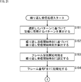
- FIG. 5 is a flowchart illustrating the repeated reception process of step S156 of FIG.
- FIG. 21 is a flowchart illustrating the repeated reception process of step S156 of FIG. 19, following FIG. 21.
- It is a flowchart explaining the frame detection process of a communication device. It is a flowchart explaining the frame reception process of a communication device. It is a flowchart explaining the same frame identification process of step S235 of FIG. It is a flowchart explaining the frame synthesis / demodulation processing of step S236 of FIG.
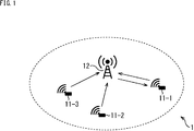
- FIG. 1 is a diagram showing a configuration example of a wireless communication system according to the first embodiment of the present technology.
- the wireless communication system 1 of FIG. 1 is configured by connecting user terminals 11-1 to 11-3 and a communication device 12 by wireless communication.
- the wireless communication between the user terminals 11-1 to 11-3 and the communication device 12 includes UL (UPLINK) communication from the user terminals 11-1 to 11-3 to the communication device 12 and the user terminal from the communication device 12. It is a two-way communication consisting of DL (DOWN LINK) communication to 11-1 to 11-3.
- UL UPLINK
- DL DOWN LINK
- User terminals 11-1 to 11-N are IoT (Internet of Things) devices equipped with one or more sensors.
- IoT Internet of Things
- the user terminal 11 when it is not necessary to distinguish the user terminals 11-1 to 11-3 as appropriate, they are collectively referred to as the user terminal 11.
- the user terminal 11 measures, for example, a measurement target, and transmits a data frame including sensor data representing the measurement result to the communication device 12.
- the user terminal 11 and the communication device 12 are time-synchronized in advance.
- the user terminal 11 selects a wireless resource (radio resource) using a hopping pattern.
- the user terminal 11 uses the selected radio resource to repeatedly transmit the same frame, which is the same data frame, for example, four times.
- the hopping pattern is shared as pattern information between the user terminal 11 and the communication device 12.
- the hopping pattern consists of one or more patterns indicating a combination of radio resources and frame numbers.
- Radio resources consist of frequency, time, and code.
- the frequency is the frequency at which a frame is transmitted.
- the time is a transmission time interval (transmission interval) for transmitting a frame.
- the code is information about the code of the frame, and in the case of the present technology, it is an initial value used for generating the code.
- the user terminal 11 transmits a control frame including control signaling to the communication device 12 prior to the transmission of the data frame.
- the control frame contains information on the radio resource of the first frame.
- the user terminal 11 determines the wireless resource for DL communication based on the wireless resource used for UL communication.
- the user terminal 11 receives a data frame transmitted from the communication device 12 as DL communication.
- the communication device 12 constitutes a base station.
- the communication device 12 detects the frame after receiving the control frame transmitted from the user terminal 11.
- the communication device 12 identifies the same frame from the detected frames by using the information of the radio resource of the first frame obtained by receiving the control frame and the known hopping pattern.
- the communication device 12 synthesizes the specified same frames and performs demodulation.
- the communication device 12 determines the wireless resource for DL communication based on the wireless resource used for UL communication, and transmits a data frame to the user terminal 11 as DL communication.
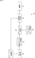
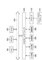
- FIG. 2 is a block diagram showing a configuration example of the communication device 12.
- the communication device 12 includes a frame detection unit 31, a detection frame list storage unit 32, a head frame information storage unit 33, a hopping pattern storage unit 34, the same frame identification unit 35, a received signal synthesis unit 36, and a demodulation unit 37. ..
- the received signal is supplied to the frame detection unit 31 and the received signal synthesis unit 36.
- the frame detection unit 31 calculates the correlation between the received signal and the known pattern, and determines that the frame has been detected when the calculated correlation value exceeds a predetermined threshold value.
- the frame detection unit 31 adds information on the radio resources (frequency, time, code) of the detected frame to the detection frame list storage unit 32.
- the detection frame list storage unit 32 stores information on the radio resource of the detected frame.
- the hopping pattern storage unit 34 stores the hopping pattern.
- the same frame identification unit 35 identifies the same frame repeatedly transmitted from the detected frames.
- the same frame identification unit 35 identifies the same frame by uniquely determining the radio resource used for the same frame to be repeatedly transmitted based on the information of the radio resource of the first frame and the hopping pattern.
- the reception signal synthesis unit 36 cuts out the reception signal of the radio resource specified by the same frame identification unit 35 and synthesizes it from the received reception signal.
- the demodulation unit 37 demodulates the signal synthesized by the reception signal synthesis unit 36.
- the radio resources used for the same frame repeatedly transmitted are uniquely based on the time synchronization, the acquisition of the radio resource information of the first frame, and the known hopping pattern. It is decided. This makes it possible to identify the same frame.
- beacon transmission for time synchronization and control signaling transmission / reception for notifying information on the radio resource of the first frame are not desirable because they consume the power of the user terminal 11.
- Second Embodiment (Example without control signaling)> Therefore, as a second embodiment of the present technology, a system that performs repetitive transmission and synthesis asynchronously and without control signaling will be described.
- the wireless communication system 1 of FIG. 1 will be referred to again for description.
- the user terminal 11 selects an arbitrary pattern from the hopping patterns shared in advance as pattern information in the wireless communication system 1, and repeatedly transmits the same frame at an arbitrary time.
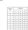
- FIG. 3 is a diagram showing an example of a frequency hopping pattern.
- the frequency hopping pattern defines the frequency used for each frame to be repeatedly transmitted.
- FIG. 3 shows a hopping pattern composed of a plurality of patterns in which the number of repeated transmissions is 4 and the number of usable frequencies is 9.
- frequencies f 8 , f 5 , f 7 , and f 0 are used for transmission of frames of frame numbers 1 to 4, respectively.
- frequencies f 7 , f 8 , f 0 , and f 5 are used for transmission of frames of frame numbers 1 to 4, respectively.
- frequencies f 6 , f 3 , f 8 and f 2 are used for transmission of frames of frame numbers 1 to 4, respectively.
- frequencies f 5 , f 4 , f 6 , and f 8 are used for transmission of frames of frame numbers 1 to 4, respectively.
- frequencies f 4 , f 1 , f 2 , and f 7 are used for transmission of frames of frame numbers 1 to 4, respectively.
- frequencies f 3 , f 0 , f 5 , and f 1 are used for transmission of frames of frame numbers 1 to 4, respectively.
- frequencies f 2 , f 6 , f 1 , and f 3 are used for transmission of frames of frame numbers 1 to 4, respectively.
- frequencies f 1 , f 7 , f 4 , and f 6 are used for transmission of frames of frame numbers 1 to 4, respectively.
- frequencies f 0 , f 2 , f 3 , and f 4 are used for transmission of frames of frame numbers 1 to 4, respectively.
- the combination of frame number and frequency is different for each pattern.
- the same frame is transmitted using frequencies f 8 , f 5 , f 7 , and f 0 .
- the time and the code which are radio resources other than the frequency, are fixed.
- the hopping pattern may be defined for the time and the sign so as to be variable.
- the time referred to here means a transmission interval for transmitting the same frame as described above.
- the code represents the initial value used to generate the Preamble / SYNC and the scramble pattern (code).
- the wireless resource used for DL communication is determined based on the wireless resource used for UL communication. For example, DL communication is started after ⁇ t from the transmission start time of the first frame to be repeatedly transmitted. For DL communication, the radio resource indicated by the pattern of pattern number 1 + ⁇ P used for UL communication is used.
- FIG. 4 is a diagram showing an example of a wireless resource used by the user terminal 11.
- the vertical axis represents frequency and the horizontal axis represents time.
- the rectangle represents a frame. The same applies to the following figures.
- the user terminal 11 uses the pattern of pattern number 1 as the hopping pattern for UL communication. Therefore, the user terminal 11 transmits the frame F1 using the frequency f 8 , transmits the frame F2 using the frequency f 5 , transmits the frame F3 using the frequency f 7 , and transmits the frame F 4 as UL communication. It is transmitted using the frequency f 0 .
- the user terminal 11 can receive the frame F1 transmitted using the frequency f 5 and receive the frame F 2 transmitted using the frequency f 4 as DL communication. The user terminal 11 can then receive the frame F3 transmitted using the frequency f 6 and receive the frame F 4 transmitted using the frequency f 8 .
- the wireless resource used for DL communication is uniquely determined from the wireless resource used for UL communication. Therefore, the user terminal 11 only needs to perform the reception processing on the corresponding frequency using the corresponding code only for the time when the reception processing needs to be performed.
- the reception process is a process including frame detection, composition, and demodulation.
- FIG. 5 is a block diagram showing a configuration example of the communication device 12.
- FIG. 5 shows a configuration example of a communication device in the case where the wireless communication system 1 is a system that repeatedly transmits and synthesizes asynchronously and without control signaling.
- the communication device 12 is composed of a frame detection unit 51, a detection frame list storage unit 32, a hopping pattern storage unit 34, the same frame identification unit 52, a received signal synthesis unit 36, and a demodulation unit 37.
- a frame detection unit 51 a detection frame list storage unit 32
- a hopping pattern storage unit 34 the same frame identification unit 52
- a received signal synthesis unit 36 a received signal synthesis unit 36
- a demodulation unit 37 a demodulation unit
- the received signal is supplied to the frame detection unit 51 and the received signal synthesis unit 36.
- the frame detection unit 51 does not know which radio resource the user terminal 11 uses to transmit the frame.
- the frame detection unit 51 always detects a frame using all available codes for all available frequencies.
- the same frame identification unit 52 identifies the same frame repeatedly transmitted from the detected frames. Specifically, the same frame identification unit 52 determines the frame of interest, which is the frame of interest, in order from the earliest detection time, with reference to the detection frame list storage unit 32.
- the same frame identification unit 52 regards the frame of interest as the first frame, and estimates the hopping pattern used for transmission based on the frequency and hopping pattern of the first frame. In the same frame identification unit 52, it is presumed that the pattern in which the frequency of the first frame and the frequency of frame number 1 in the hopping pattern match is the hopping pattern used for transmission. The same frame identification unit 52 identifies the second and subsequent frames from the detected frames based on the frequency and time indicated by the estimated hopping pattern.
- the reception signal synthesis unit 36 cuts out the reception signal transmitted by the radio resource specified by the same frame identification unit 52 from the received reception signal and synthesizes it.
- the demodulation unit 37 demodulates the signal synthesized by the reception signal synthesis unit 36.
- the communication device 12 determines the radio resource used for DL communication in the same manner as the user terminal 11 based on the detection time of the frame of interest and the estimated hopping pattern. The communication device 12 transmits a frame using the determined radio resource.
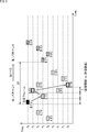
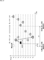
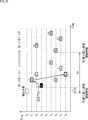
- FIG. 6 is a diagram showing an example of a wireless resource used by the communication device 12.
- frame B F1, frame B: F2, frame C: F1, frame B: F3, frame C: F2, frame B: F4, frame C: F3 and frame C: F4 are detected in order.
- Frame B F1, frame B: F2, frame B: F3, and frame C: F4 are frames transmitted from the user terminal 11 to be received.
- the communication device 12 determines the frame B: F1 having the earliest detection time as the frame of interest.
- the communication device 12 regards the frame of interest as the first frame.
- the communication device 12 uses a hopping pattern (the pattern of pattern number 1 in FIG. 3) in which the same frequency as the frequency f 8 of frame B: F1, which is the first frame, is used for frame number 1, as a hopping pattern used for transmission. Presumed to be.
- the communication device 12 performs pattern matching on the detected frame using the pattern of pattern number 1 (frequency f 8 , f 5 , f 7 , f 0 ). As a result of pattern matching, the communication device 12 identifies frames B: F2, frame B: F3, and frame B: F4 received using the frequencies f 5 , frequency f 7 , and frequency f 0 as the same frame. ..
- the interval from the detection time of: F4 is the time interval in which the tolerance is added or subtracted for each transmission interval.
- the communication device 12 determines the transmission start time of DL communication after ⁇ t from the transmission start time of the first frame B: F1 to be repeatedly transmitted.
- the communication device 12 uses the radio resources (frequency f 5 , f 4 , f 6 , f 8 ) indicated by the pattern of the determined pattern number 4 as DL communication, and frame B: F1, frame B: F2, frame B. : F3 and frame B: F4 can be received.
- the frame with the earliest detection time is regarded as the first frame, and pattern matching is performed on the detected frame using a hopping pattern, so that the same frame repeatedly transmitted can be specified.
- the communication device 12 cannot always detect the first frame of repeated transmission.
- FIG. 7 is a diagram showing a state of the radio resource used by the communication device 12 when the detection of the first frame fails.
- the communication device 12 determines the frame B: F2 having the earliest detection time as the frame of interest.
- the communication device 12 regards the frame of interest as the first frame.
- the communication device 12 is a hopping pattern used for transmitting a hopping pattern (pattern number 4 in FIG. 3) in which the same frequency as the frequency f 8 of the frame B: F2, which is the first frame, is used for the frame number 1. I presume that.
- the communication device 12 performs pattern matching on the detected frame using the pattern of pattern number 4 (frequency f 5 , f 4 , f 6 , f 8 ). As a result of pattern matching, no frames received using frequency f 4 have been detected.
- the frame received using the frequency f 6 is frame C: F 4. Frames received using frequency f 8 have not been detected. Therefore, the communication device 12 identifies the frame C: F4, which is a frame received using the frequency f 6 , as the same frame.
- the communication device 12 mistakenly identifies and synthesizes frames C: F4 transmitted from different user terminals 11 as the same frame.
- the communication device 12 determines the transmission start time of DL communication after ⁇ t from the transmission start time of the first frame B: F2 to be repeatedly transmitted.
- the pattern of pattern number 7 has frequencies f 2 , f 6 , f 1 , and f 3 as shown in frames B: F1 to B: F4 of DL communication in FIG.
- the actual first frame is frame B: F1.
- the transmission start time of DL communication is ⁇ t after the transmission start time of the first frame B: F1 to be repeatedly transmitted, as shown in FIG.
- the hopping pattern actually used in DL communication is the pattern of pattern number 4 as shown in frames B: F1 to B: F4 of DL communication in FIG. (Frequencies f 5 , f 4 , f 6 , f 8 ).
- the wireless resources used by the communication device 12 and the user terminal 11 do not match, and the user terminal 11 cannot receive the DL frame, which is a frame for DL communication.
- the frame with the earliest detection time is regarded as the first frame, but also the frame of frame number 2 to the frame number (number of repeated transmissions-1) is regarded as the frame that may be the first frame and is the same. It is necessary to identify the frame.
- a hopping pattern of a code limited so that the frame number to be repeatedly transmitted is uniquely determined based on the code is used.
- the receiving side can uniquely determine which frame the detected frame is.
- FIG. 8 is a block diagram showing a configuration example of a wireless communication system according to a third embodiment of the present technology.
- the wireless communication system 101 of FIG. 8 is configured by connecting user terminals 111-1 to 111-3 and a communication device 112 by wireless communication.
- the wireless communication between the user terminals 111-1 to 111-3 and the communication device 112 includes UL communication from the user terminals 111-1 to 111-3 to the communication device 112 and communication from the communication device 112 to the user terminals 111-1 to 111-1 to 112. Bidirectional communication consisting of DL communication to 111-3.
- User terminals 111-1 to 111-N are IoT devices equipped with one or more sensors.
- the user terminals 111-1 to 111-N are, for example, among cameras, microphones, acceleration sensors, angular velocity sensors, geomagnetic sensors, illuminance sensors, temperature sensors, humidity sensors, moisture sensors, optical sensors, barometric pressure sensors, positioning sensors and the like. , With at least one sensor.
- the user terminals 111-1 to 111-3 are collectively referred to as the user terminal 111.
- the user terminal 111 and the communication device 112 share a frequency hopping pattern, a code hopping pattern, and a time hopping pattern.
- the frequency hopping pattern, the code hopping pattern, and the time hopping pattern are configured so that the frame number is specified based on the code on the receiving side.
- the user terminal 111 measures, for example, a measurement target, and transmits a data frame including sensor data representing the measurement result to the communication device 112.
- the user terminal 111 selects a radio resource using each hopping pattern of frequency, code, and time.
- the user terminal 111 uses the selected radio resource to repeatedly transmit the same frame, which is the same data frame, for example, four times.
- the user terminal 111 determines the radio resource for DL communication based on the radio resource used for UL communication.
- the user terminal 111 receives the same frame transmitted from the communication device 112 as DL communication by using the wireless resource of DL communication.
- the communication device 112 constitutes a base station.
- the communication device 112 detects a frame transmitted from the user terminal 111.
- the communication device 112 identifies the same frame from the detected frames by using the hopping pattern.
- the communication device 112 determines the hopping pattern by specifying the frame number of the detected frame based on the code.
- the communication device 112 identifies the same frame by pattern matching between the detected frame and the determined hopping pattern.
- the communication device 112 synthesizes the same specified frames and performs demodulation.
- the communication device 112 determines the radio resource for DL communication based on the radio resource used for UL communication, and transmits the data frame to the user terminal 111 using the radio resource for DL communication as DL communication.
- the frame number of the detected frame is specified based on the code. As a result, the same frame can be accurately identified without transmitting time synchronization or control frames.
- FIG. 9 is a block diagram showing a configuration example of the user terminal 111.
- the user terminal 111 is composed of a wireless communication unit 121, a wireless control unit 122, a frame generation unit 123, a sensor 124, a wireless resource determination unit 125, a storage unit 126, a frame detection unit 127, and a frame demodulation unit 128.
- the wireless communication unit 121 transmits and receives wireless signals to and from the communication device 112.
- the wireless communication unit 121 converts the frame generated by the frame generation unit 123 into a wireless signal according to the control signal supplied from the wireless control unit 122, and transmits the frame to the communication device 112.
- the wireless communication unit 121 receives the radio wave transmitted from the communication device 12 according to the control signal supplied from the wireless control unit 122, and converts it into a wireless signal.
- the radio communication unit 121 outputs the converted radio signal to the frame detection unit 127 and the frame demodulation unit 128.
- the wireless control unit 122 is composed of a CPU (Central Processing Unit), a ROM (Read Only Memory), a RAM (Random Access Memory), and the like.
- the wireless control unit 122 executes a program stored in a ROM or the like to control the wireless communication unit 121.
- the radio control unit 122 controls the radio communication unit 121 so as to transmit the frame supplied from the frame generation unit 123 by using the transmission time and the transmission frequency supplied from the radio resource determination unit 125. Further, the radio control unit 122 controls the radio communication unit 121 so as to receive the frame using the reception time and the reception frequency supplied from the radio resource determination unit 125, if necessary.
- the frame generation unit 123 generates a data frame including the sensor data supplied from the sensor 124, and outputs the generated data frame to the wireless control unit 122.
- a code supplied from the radio resource determination unit 125 is used to generate the data frame.
- the sensor 124 measures information outside and inside the terminal, and outputs sensor data representing the measurement result to the frame generation unit 123.
- the radio resource determination unit 125 determines the radio resource for transmitting each data frame by using the hopping pattern acquired from the storage unit 126.
- the radio resource determination unit 125 uses the determined code as an initial value to generate a Preamble / SYNC and a scramble pattern, respectively. Further, the radio resource determination unit 125 determines the radio resource used for DL communication based on the radio resource used for UL communication.
- the storage unit 126 stores the hopping pattern used for determining the radio resource.
- the frame detection unit 127 detects a frame from the received signal supplied from the wireless communication unit 121. Specifically, the frame detection unit 127 extracts a signal having a target frequency from the wide area signal from the received signal supplied from the wireless communication unit 121, and generates a known pattern by using Preamble / SYNC and a scramble pattern.
- the frame detection unit 127 calculates the correlation value between the signal and the known pattern, and determines that the frame has been detected when the correlation value becomes a certain value or more. When the frame detection unit 127 succeeds in detecting the frame, the frame detection unit 127 outputs the detected radio resource to the frame demodulation unit 128.
- the frame demodulation unit 128 synthesizes and demodulates frames using the received signal supplied from the wireless communication unit 121. Specifically, the frame demodulation unit 128 extracts the signal of the portion corresponding to the frame from the received signal based on the radio resources for the number of frames detected by the frame detection unit 127.
- the frame demodulation unit 128 descrambles the extracted signal with the scramble pattern supplied from the radio resource determination unit 125, and synthesizes the descrambling signal.
- the frame demodulation unit 128 takes out the Payload from the synthesized signal, decodes the error correction code, and performs error detection processing using CRC.
- the frame demodulation unit 128 succeeds in demodulating the frame, the frame demodulation unit 128 notifies the data to the upper layer.
- the user terminal 111 may be configured without the frame detection unit 127 and the frame demodulation unit 128.
- FIG. 10 is a block diagram showing a configuration example of the communication device 112.
- the communication device 112 includes a wireless communication unit 141, a wireless control unit 142, a frame generation unit 143, a radio resource determination unit 144, a storage unit 145, a frame detection unit 146, the same frame identification unit 147, and a frame demodulation unit 148. ..
- the wireless communication unit 141 transmits and receives a wireless signal to and from the user terminal 111.
- the wireless communication unit 141 receives the radio wave transmitted from the user terminal 111 and converts it into a wireless signal according to the control signal supplied from the wireless control unit 142.
- the radio communication unit 141 outputs the converted radio signal to the frame detection unit 146 and the frame demodulation unit 148.
- the wireless communication unit 141 converts the frame generated by the frame generation unit 143 into a wireless signal according to the control signal supplied from the wireless control unit 142, and transmits the frame to the user terminal 111.
- the wireless control unit 142 is composed of a CPU, ROM, RAM, and the like.
- the wireless control unit 142 executes a program stored in a ROM or the like to control the wireless communication unit 141.
- the radio control unit 142 controls the radio communication unit 141 so as to receive a frame using the reception time and reception frequency supplied from the radio resource determination unit 144. Further, the radio control unit 142 uses the transmission time and transmission frequency supplied from the radio resource determination unit 144 as necessary to transmit the frame supplied from the frame generation unit 143 to the radio communication unit 141. Control.
- the frame generation unit 143 generates a data frame to be transmitted by the communication device 112 by using the code supplied from the radio resource determination unit 144.
- the frame generation unit 143 outputs the generated data frame to the radio control unit 142.
- the radio resource determination unit 144 determines the radio resource (time, frequency, code) to transmit each data frame by using the hopping pattern acquired from the storage unit 145.
- the radio resource determination unit 144 uses the determined code as an initial value to generate a Preamble / SYNC and a scramble pattern, respectively.
- the radio resource determination unit 144 has a DL transmission list in which the terminal ID and the radio resource used for DL transmission are registered.
- the radio resource determination unit 144 determines the radio resource used for DL communication based on the radio resource used for UL communication.
- the radio resource determination unit 144 registers the terminal ID and the radio resource used for DL transmission in the DL transmission list.
- the radio resource determination unit 144 extracts the radio resource of the DL transmission list and outputs the code of the radio resource to the frame generation unit 143.
- the radio resource determination unit 144 outputs the frequency and time of the radio resource to the radio control unit 142.
- the storage unit 145 stores the hopping pattern used for determining the radio resource.
- the frame detection unit 146 detects a frame from the received signal supplied from the wireless communication unit 141.
- the frame detection method is the same as the frame detection method in the frame detection unit 127 of FIG.
- the frame detection unit 146 succeeds in detecting the frame, the detected radio resource information is registered as an entry in the detection frame list of the same frame identification unit 147.
- the same frame identification unit 147 has a detection frame list in which the radio resources of the detected frames are registered.
- the same frame identification unit 147 identifies the same frame repeatedly transmitted from the detected frames by using the information of the radio resource in the detection frame list and the hopping pattern acquired from the storage unit 145.
- the same frame identification unit 147 When the same frame identification unit 147 succeeds in identifying the same frame, the same frame identification unit 147 registers the specified radio resource information of the same frame as an entry in the same frame list of the frame demodulation unit 148.
- the frame demodulation unit 148 has the same frame list in which radio resources of the same frame are registered. When a plurality of entries exist in the same frame list, the frame demodulation unit 148 synthesizes and demodulates frames by using the received signal supplied from the wireless communication unit 121.
- the frame composition / demodulation method is the same composition / demodulation method as the composition / demodulation method in the frame demodulation unit 128 of FIG.
- the frame demodulation unit 148 When the frame demodulation unit 148 succeeds in demodulating the frame, the frame demodulation unit 148 notifies the upper layer of the data. Further, when the frame demodulation unit 148 succeeds in demodulating the frame, the frame demodulation unit 148 outputs the radio resource of the same frame to the radio resource determination unit 144 as the radio resource of UL communication.
- the communication device 112 may be configured without the frame generator 143.
- FIG. 11 is a diagram showing a configuration example of frames transmitted and received by the wireless communication system 101.
- the frame consists of Preamble / SYNC and Payload fields.
- Payload has fields such as ID, DATA, and CRC (Cyclic Redundancy Check).
- the ID includes a terminal-specific identifier.
- DATA includes sensor data.
- the CRC is a value calculated for ID and DATA, and includes a value used by the receiving side to determine successful reception.
- the frame generation unit 123 and the frame generation unit 143 perform error correction and interleave on the series in which ID, DATA, and CRC are concatenated, and generate a payload.
- the frame generation unit 123 and the frame generation unit 143 generate a data frame (Frame) by concatenating the Payload and the preamble / SYNC of the data frame, and then exclusive-ORing each bit with the scramble pattern of the data frame. ..
- the Preamble / SYNC and scramble patterns used in the frame are patterns generated from the code (initial value) in the radio resource determination unit 125 and the radio resource determination unit 144.
- hopping pattern used to generate the radio resource.
- a hopping pattern is defined for each time, frequency, and code.
- an example of four times of repeated transmissions is shown.
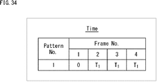
- FIG. 12 is a diagram showing an example of a time hopping pattern.
- the time hopping pattern indicates the transmission interval at which each frame is repeatedly transmitted.
- the number of patterns is limited to one.
- the value of the transmission interval is not particularly limited.
- the time hopping pattern is composed of one pattern.
- transmission interval 0 transmission interval T 1 , transmission interval T 1 , and transmission interval T 1 are used for transmission of frames of frame numbers 1 to 4, respectively.
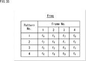
- FIG. 13 is a diagram showing an example of a frequency hopping pattern.
- the frequency hopping pattern indicates the frequency used for each frame to be repeatedly transmitted.
- FIG. 13 shows a pattern in which there are nine usable frequencies and all frequencies are evenly assigned.
- the frequency hopping pattern is not limited to the example of FIG.
- frequencies f 8 , f 5 , f 7 , and f 0 are used for transmission of frames of frame numbers 1 to 4, respectively.
- frequencies f 7 , f 8 , f 0 , and f 5 are used for transmission of frames of frame numbers 1 to 4, respectively.
- frequencies f 6 , f 3 , f 8 and f 2 are used for transmission of frames of frame numbers 1 to 4, respectively.
- frequencies f 5 , f 4 , f 6 , and f 8 are used for transmission of frames of frame numbers 1 to 4, respectively.
- frequencies f 4 , f 1 , f 2 , and f 7 are used for transmission of frames of frame numbers 1 to 4, respectively.
- frequencies f 3 , f 0 , f 5 , and f 1 are used for transmission of frames of frame numbers 1 to 4, respectively.
- frequencies f 2 , f 6 , f 1 , and f 3 are used for transmission of frames of frame numbers 1 to 4, respectively.
- frequencies f 1 , f 7 , f 4 , and f 6 are used for transmission of frames of frame numbers 1 to 4, respectively.
- frequencies f 0 , f 2 , f 3 , and f 4 are used for transmission of frames of frame numbers 1 to 4, respectively.
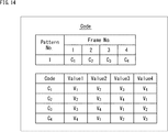
- FIG. 14 is a diagram showing an example of a sign hopping pattern.
- the sign hopping pattern indicates a combination of the initial values used to generate the preamble / SYNC and the scramble pattern used to generate each frame to be repeatedly transmitted.
- the number of patterns is not limited, and may be composed of a plurality of patterns.
- the sign hopping pattern is composed of one pattern.
- reference numerals C 1 , code C 2 , code C 3 , and code C 4 are used for transmission of frames of frame numbers 1 to 4, respectively.
- V 1 , V 2 , V 3 , and V 4 are used as Value 1 to Value 4, respectively.
- code C 2 , V 2 , V 3 , V 4 , and V 5 are used as Value 1 to Value 4, respectively.
- code C 3 , V 3 , V 4 , V 1 , and V 2 are used as Value 1 to Value 4 , respectively.
- code C 1 , V 4 , V 1 , V 2 , and V 3 are used as Value 1 to Value 4 , respectively.
- FIG. 15 is a diagram showing a configuration example of a gold code generator as a pseudo-random number generator used for generating Preamble / SYNC and scramble patterns.
- the gold code generator 151 of FIG. 15 is four pseudo-random number generators 161-1 to 161-4 that output two M sequences and two exclusive OR (XOR) arithmetic units 171-1 and 171-2. It is composed of.
- the gold code generator 151 is used for the radio resource determination unit 125 and the radio resource determination unit 144.
- Value1 of the code C is input to the pseudo-random number generator 161-1 as an initial value.
- Value 2 of the code C is input to the pseudo-random number generator 161-2 as an initial value.
- the pseudo-random number generator 161-1 and the pseudo-random number generator 161-2 input initial values to generate random numbers.
- the value (random number) output from the pseudo-random number generator 161-1 is input to the arithmetic unit 171-1.
- the value (random number) output from the pseudo-random number generator 161-2 is input to the arithmetic unit 171-1.
- the arithmetic unit 171-1 obtains Preamble / SYNC (pseudo-random number) by integrating the values supplied from the pseudo-random number generators 161-1 and 161-2. At this time, Preamble / SYNC obtains a length that matches the Preamble / SYNC length of the frame.
- Value3 of the code C is input to the pseudo-random number generator 161-3 as an initial value.
- Value 4 of code C is input to the pseudo-random number generator 161-4 as an initial value.
- the pseudo-random number generator 161-3 and the pseudo-random number generator 161-4 input initial values to generate random numbers.
- the value (random number) output from the pseudo-random number generator 161-3 is input to the arithmetic unit 171-2.
- the value (random number) output from the pseudo-random number generator 161-2 is input to the arithmetic unit 171-2.
- the arithmetic unit 171-2 obtains a scramble pattern (pseudo-random number) by integrating the values supplied from the pseudo-random number generators 161-3 and 161-4. At this time, the scramble pattern obtains a length that matches the frame length.
- FIG. 16 is a diagram showing a detection frame list in the communication device 112.
- entry 1 information on a radio resource whose time is T'+ T 1 , whose frequency is f 5 , and whose code is C 2 is registered.
- entry 2 information on a radio resource whose time is T'+ 2T 1 , whose frequency is f 2 , and whose code is C 1 is registered.
- entry 3 information on a radio resource whose time is T'+ 2T 1 , whose frequency is f 7 , and whose code is C 3 is registered.
- entry 4 information on a radio resource whose time is T'+ 3T 1 , whose frequency is f 0 , and whose code is C 4 is registered.
- entry 5 information on a radio resource having a time of T'+ 3T 1 , a frequency of f 6 , and a code of C 2 is registered.
- entry 6 information on a radio resource having a time of T'+ 4T 1 , a frequency of f 1 , and a code of C 3 is registered.
- entry 7 information on a radio resource whose time is T'+ 5T 1 , whose frequency is f 3 , and whose code is C 4 is registered.
- FIG. 17 is a diagram showing an example in which the communication device 12 identifies the same frame from the detected frames and then performs DL transmission.
- the frames of entries 1 to 7 registered in the detection frame list of FIG. 16 are assigned entry numbers and are shown at positions of frequencies corresponding to each in the order of detection time. Further, on the right side of the DL repeat transmission start time, frames F1 to F4 to be DL transmitted are shown at their respective frequencies in the order of their respective transmission times. Further, the respective codes are also shown in the frames of entries 1 to 7 and the frames F1 to F4 transmitted by DL.
- the detected code is (C 2 ). Therefore, the code of the frame of interest is specified to be the code of frame number 2 based on the code hopping pattern (FIG. 14).
- the pattern used for repeated transmission is pattern number 1. Can be extracted.
- the start time (T') of the repeated transmission of UL communication is set. Calculated correctly.
- the rules shown in the equations (1) and (2) described later are defined, and the user terminal 111 and the communication device 112 It is shared.
- the user terminal 111 and the communication device 112 have a pattern number 4 (f5) used for repeated transmission of DL communication shown in FIG. 17 according to the equation (1) and the frequency hopping pattern (FIG. 13).
- F4, f6, f8) (FIG. 13) are calculated respectively.
- the user terminal 111 and the communication device 112 calculate the start time (T'+ ⁇ t) of repeated transmission of DL communication by the equation (2), respectively.
- the user terminal 111 can receive the DL frame.
- a hopping pattern of a code limited so that the frame number to be repeatedly transmitted is uniquely determined based on the code is used.
- the receiving side since the receiving side uniquely determines the number of the detected frame, it is possible to correctly identify the same frame by performing pattern matching only once for the frame of interest.
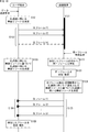
- FIG. 18 is a flowchart illustrating the processing of the entire wireless communication system 101.
- the user terminal 111 When the user terminal 111 receives the data transmission request from the upper layer, the user terminal 111 starts the process of FIG.
- step S101 the user terminal 111 determines the radio resource used for UL communication.
- step S102 the user terminal 111 repeatedly transmits the UL frame (1 to n), which is a UL communication frame, to the communication device 112 using the determined radio resource.
- step S121 the communication device 112 constantly performs frame detection, and detects UL frames (1 to n) transmitted from the user terminal 111.
- the communication device 112 When the communication device 112 receives the same frame identification request supplied from the upper layer, the communication device 112 performs the processes after step S122.
- step S122 the communication device 112 identifies the same frame from the frames detected in step S121 as the same frame identification process.
- step S123 the communication device 112 synthesizes and demodulates the same specified frame as the frame synthesis / demodulation process.
- step S124 the communication device 112 determines the radio resource to be used for DL communication based on the radio resource estimated to be used for UL communication from the UL frame detection / demodulation result.
- each process of steps S122 to S124 is collectively referred to as a frame reception process.
- step S125 the communication device 112 repeatedly transmits the DL frame (1 to n), which is a frame for DL communication, to the user terminal 111 using the determined radio resource.
- step S103 the user terminal 111 determines the radio resource used for DL communication based on the radio resource used for UL communication.
- step S104 the user terminal 111 uses the determined radio resource to detect the frame only at the time when the DL frame is transmitted.
- step S105 the user terminal 111 synthesizes the detected frame and demodulates it.
- determining the radio resource used for DL communication based on the radio resource used for UL communication specifically means determining the hopping pattern used for DL communication and the start time of repeated transmission.
- rules as shown in the following equations (1) and (2) are defined and shared.
- ⁇ P 2 is used.
- the user terminal 111 can detect the frame only at the time when the DL frame is transmitted. As a result, power saving can be achieved.
- FIG. 19 is a flowchart illustrating a frame transmission / reception process of the user terminal 111.
- step S151 the wireless control unit 122 determines whether or not a data transmission request has been received from an upper layer application (not shown). If it is determined in step S151 that the data transmission request has been received, the process proceeds to step S152.
- step S152 the radio resource determination unit 125 selects an arbitrary pattern from the hopping patterns of the storage unit 126 (corresponding to step S101 in FIG. 18).
- the frequency pattern and the time pattern are output to the wireless control unit 122.
- the code pattern is output to the frame generation unit 123.
- step S153 the wireless control unit 122 sets the repeat transmission start time to an arbitrary time.
- step S154 the wireless control unit 122 repeatedly executes the transmission process (corresponding to step S102 in FIG. 18). This repetitive transmission process will be described later with reference to FIG. By the process of step S154, the same frame is repeatedly transmitted a predetermined number of times.
- step S155 the radio control unit 122 determines whether or not frame reception is necessary. If it is determined that frame reception is necessary, the process proceeds to step S156.
- step S156 the wireless control unit 122 repeatedly executes the reception process (corresponding to steps S103 to S105 in FIG. 18). This repetitive reception process will be described later with reference to FIGS. 21 and 22.
- step S156 the same frame transmitted from the communication device 112 is repeatedly received a predetermined number of times.
- step S156 After being repeatedly received in step S156, the frame transmission / reception process of the user terminal 111 ends.
- step S151 when it is determined in step S151 that the data transmission request has not been received, or when it is determined in step S155 that frame reception is not necessary, the frame transmission / reception process is similarly terminated.
- FIG. 20 is a flowchart illustrating the iterative transmission process of step S154 of FIG.
- step S171 the wireless control unit 122 sets the frame transmission start time to the repeat transmission start time.
- step S172 the radio control unit 122 initializes the frame number F to 1.
- step S173 the radio control unit 122 determines whether or not the frame number F is equal to or less than the number of repeated transmissions. If it is determined in step S173 that the frame number F is equal to or less than the number of repeated transmissions, the process proceeds to step S174.
- step S174 the radio control unit 122 and the frame generation unit 123 extract the radio resource (frequency, time, code) corresponding to the frame number F of the pattern selected by the radio resource determination unit 125.
- step S175 the frame generation unit 123 generates a frame to be transmitted by using the extracted code.
- step S176 the radio control unit 122 adds the extracted time (transmission interval) to the frame transmission start time.
- step S177 the wireless control unit 122 waits until the frame transmission start time is reached. If it is determined in step S177 that the frame transmission start time has come, the process proceeds to step S178.
- step S178 the wireless control unit 122 controls the wireless communication unit 121 and causes the frame supplied from the frame generation unit 123 to be transmitted using the extracted frequency.
- step S179 the radio control unit 122 increments the frame number F, and then the process returns to step S173.
- step S173 If it is determined in step S173 that the frame number F is greater than the number of repeated transmissions, the repeated transmission process ends.
- 21 and 22 are flowcharts illustrating the repeated reception process of step S156 of FIG.
- the radio resource determination unit 125 calculates a pattern to be used for reception (DL communication) based on the pattern selected in step S152 of FIG.
- the above-mentioned equation (1) or equation (2) is used for calculating the hopping pattern.
- the frequency pattern and the time pattern are output to the wireless control unit 122.
- the code pattern is output to the frame generation unit 123.
- step S182 the wireless control unit 122 calculates the repeated reception start time based on the repeated transmission start time.
- step S183 the wireless control unit 122 repeatedly sets the frame reception start time to the reception start time.
- step S184 the radio control unit 122 initializes the frame number F to 1.
- step S185 of FIG. 22 it is determined whether or not the frame number F is equal to or less than the number of repeated transmissions. If it is determined in step S185 that the frame number F is equal to or less than the number of repeated transmissions, the process proceeds to step S186.
- step S186 the radio control unit 122 and the frame generation unit 123 extract the radio resource (frequency, time, code) corresponding to the frame number F of the pattern selected by the radio resource determination unit 125.
- step S187 the radio control unit 122 adds the time (transmission interval) extracted in step S186 to the frame reception start time.
- step S188 the radio control unit 122 waits until the frame reception start time is reached. If it is determined in step S188 that the frame reception start time has come, the process proceeds to step S189.
- step S189 the wireless communication unit 121 receives the radio signal of the frequency extracted in step S186.
- the wireless communication unit 121 outputs the received wireless signal to the frame detection unit 127.
- step S190 the frame detection unit 127 executes the frame detection process using the code extracted in step S186.
- step S191 the frame detection unit 127 determines whether or not the frame detection is successful. If it is determined in step S191 that the frame detection is successful, the process proceeds to step S192.
- step S192 the frame detection unit 127 cuts out the signal of the detected frame, descrambles it, and holds it.
- step S192 is skipped and the process proceeds to step S193.
- step S193 the radio control unit 122 increments the frame number F, and then the process returns to step S185.
- step S185 If it is determined in step S185 that the frame number F is greater than the number of repeated transmissions, the process proceeds to step S194.
- step S194 the frame detection unit 127 determines whether or not there are a plurality of detected frames. If it is determined in step S194 that a plurality of detected frames exist, the process proceeds to step S195.
- step S195 the frame detection unit 127 synthesizes the signal held in step S192.
- step S195 is skipped and the process proceeds to step S196.
- step S196 the frame demodulation unit 128 executes the demodulation process.
- step S197 the frame demodulation unit 128 determines whether or not the frame demodulation is successful. If it is determined in step S197 that the demodulation of the frame is successful, the process proceeds to step S198.
- step S198 the frame demodulation unit 128 notifies the upper layer of the data acquired from the frame.
- step S197 If it is determined in step S197 that the frame demodulation has failed, the process skips step S198.
- the processing of the communication device 12 includes the frame detection processing of step S121 (FIG. 23), the frame reception processing of steps S122 to S124 (FIG. 24), and the repeated transmission processing of step S125, as described above with reference to FIG. It can be divided into three (Fig. 27). Each of these processes is executed in parallel. Hereinafter, each process will be described in detail.
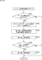
- FIG. 23 is a flowchart illustrating the frame detection process of the communication device 112.
- the process of FIG. 23 is a process corresponding to the frame detection process of step S121 of FIG.
- step S211 the wireless control unit 142 waits until it is determined that the frame reception start time has come. If it is determined in step S211 that the frame reception start time has come, the process proceeds to step S212.
- step S212 the radio communication unit 141 receives the radio signal of the target frequency according to the control signal supplied from the radio control unit 142.
- step S213 the frame detection unit 146 executes the frame detection process using the target code.
- step S214 the frame detection unit 146 determines whether or not the frame detection is successful. If it is determined in step S214 that the frame detection is successful, the process proceeds to step S215.
- step S215 the frame detection unit 146 registers the information of the radio resource (frequency, time, code) that detected the frame in the detection frame list of the same frame identification unit 147.
- step S215 after registration in the detection frame list, or in step S214, if it is determined that the frame detection was not successful, the frame detection process ends.
- the process of FIG. 23 is always and repeatedly executed. Further, the process of FIG. 23 needs to be executed in parallel by designating the target frequency and the target code so that the process of all the usable codes is performed for all the usable frequencies.
- FIG. 24 is a flowchart illustrating a frame reception process of the communication device 112.
- step S231 the same frame identification unit 147 determines whether or not the same frame identification request has been received. For example, when the same frame identification request is supplied from the upper layer of the communication device 112, it is determined in step S231 that the same frame identification request has been received, and the process proceeds to step S232.
- step S232 the same frame identification unit 147 determines whether or not an entry exists in the detection frame list. If it is determined in step S232 that an entry exists in the detection frame list, the process proceeds to step S233.
- step S233 the same frame identification unit 147 pays attention to the entry having the earliest detection time.
- step S234 the same frame identification unit 147 temporarily clears the same frame list of the frame demodulation unit 148.
- step S235 the same frame identification unit 147 executes the same frame identification process (corresponding to step S122 in FIG. 18). This same frame identification process will be described later with reference to FIG. The same frame is specified by the process of step S235.
- step S236 the frame demodulation unit 148 executes frame synthesis / demodulation processing (corresponding to steps S123 and S124 in FIG. 18). This frame composition / demodulation process will be described later with reference to FIG. The same frame is synthesized by the process of step S236, and the frame demodulation process is performed.
- step S237 the same frame identification unit 147 deletes the attention entry.
- step S237 the process returns to step S232, and the subsequent processing is repeated.
- step S231 If it is determined in step S231 that the same frame identification request has not been received, or if it is determined in step S232 that no entry exists in the detection frame list, the frame reception process is terminated.
- the user terminal 111 is still in the process of repeatedly transmitting the noted entry (detected frame). In this case, if the entry of interest is immediately deleted from the detection frame list as in this process, the number of frames judged to be the same frame may decrease, and the gain obtained by synthesis may decrease. is there.
- whether or not to delete the attention entry is determined by using the number of frames specified as the same frame, whether demodulation is successful, or the detection time of the attention entry. You may.
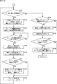
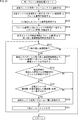
- FIG. 25 is a flowchart illustrating the same frame identification process in step S235 of FIG. 24.
- step S251 the same frame identification unit 147 adds a noteworthy entry to the same frame list.
- step S252 the same frame identification unit 147 extracts a pattern (code) and a frame number that match the code of the entry of interest.
- step S253 the same frame identification unit 147 sets a frame number in F.
- step S254 the same frame identification unit 147 extracts a pattern (frequency) in which the frame number F and the frequency of the entry of interest match.
- step S255 the same frame identification unit 147 calculates the repetitive transmission start time from the detection time of the attention entry and the frame number F.
- step S256 the same frame identification unit 147 determines whether or not F is smaller than the number of repeated transmissions. If it is determined in step S256 that F is less than the number of repeated transmissions, the process proceeds to step S257.
- step S257 the same frame identification unit 147 calculates the radio resource used for the frame with frame number F + 1 from the extracted pattern and the repeated transmission start time.
- step S258 the same frame identification unit 147 determines whether or not an entry whose detection time is within the range of (calculated time ⁇ a) exists in the detection frame list. If it is determined in step S258 that an entry whose detection time is within the range of (calculated time ⁇ a) exists in the detection frame list, the process proceeds to step S259.
- step S259 the same frame identification unit 147 determines whether or not the frequency / code of the entry matches the calculated frequency / code. If it is determined in step S259 that the frequency / code of the entry matches the calculated frequency / code, the process proceeds to step S260.
- step S260 the same frame identification unit 147 adds the entry to the same frame list. After adding the entry, the process proceeds to step S261.
- step S258 when it is determined that an entry whose detection time is within the range of (calculated time ⁇ a) does not exist in the detection frame list, or in step S259, the frequency / code of the entry is calculated. Similarly, when it is determined that the frequencies and codes do not match, the process proceeds to step S261.
- step S261 the same frame identification unit 147 increments F. After incrementing F, the process returns to step S256, and the subsequent processing is repeated.
- step S256 if it is determined in step S256 that F is larger than the number of repeated transmissions, the same frame identification process ends.
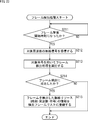
- FIG. 26 is a flowchart illustrating the frame composition / demodulation process of step S236 of FIG. 24.
- step S271 the frame demodulation unit 148 cuts out signals for all entries (frames) in the same frame list, descrambles them, and holds them.
- step S272 the frame demodulation unit 148 determines whether or not there are a plurality of entries in the same frame list. If it is determined in step S272 that a plurality of entries exist in the same frame list, the process proceeds to step S273.
- step S273 the frame demodulation unit 148 synthesizes the held signal. After synthesizing the signals, the process proceeds to step S274.
- step S273 is skipped and the process proceeds to step S274.
- step S274 the frame demodulation unit 148 executes the demodulation process.
- step S275 the frame demodulation unit 148 determines whether or not the frame has been successfully demodulated. If it is determined in step S275 that the frame demodulation is successful, the process proceeds to step S276.
- step S276 the frame demodulation unit 148 notifies the upper layer of the data acquired from the frame.
- step S277 the radio control unit 142 determines whether or not DL transmission is necessary. If it is determined in step S277 that DL transmission is necessary, the process proceeds to step S278. At this time, the frame demodulation unit 148 outputs the specified radio resource of the same frame to the radio resource determination unit 144 as a radio resource for UL communication.
- step S278 the radio resource determination unit 144 calculates the radio resource used for DL transmission.
- step S279 the radio resource determination unit 144 registers the terminal ID and the radio resource used for DL transmission in the DL transmission list. After registering the wireless resource, the frame composition / demodulation process is completed.
- step S275 when it is determined in step S275 that the demodulation of the frame has not been successful, or when it is determined in step S277 that DL transmission is not necessary, the frame composition / demodulation process is similarly terminated. To.
- FIG. 27 is a flowchart illustrating a repetitive transmission process of the communication device 112.
- This repeated transmission process is a process corresponding to step S125 in FIG. 18, and is a process performed by the communication device 112 for each entry in the DL transmission list.
- step S291 the wireless control unit 142 sets the frame transmission start time to the repeat transmission start time.
- step S292 the radio control unit 142 initializes the frame number F to 1.
- step S293 the radio control unit 142 determines whether or not the frame number F is equal to or less than the number of repeated transmissions. If it is determined in step S293 that the frame number F is equal to or less than the number of repeated transmissions, the process proceeds to step S294.
- step S294 the radio control unit 142 extracts the radio resource (frequency, time, code) corresponding to the frame number F of the pattern of the target entry.
- step S295 the frame generation unit 143 generates a frame to be transmitted by using the extracted code.
- step S296 the wireless control unit 142 adds the extracted time (transmission interval) to the frame transmission start time.
- step S297 the radio control unit 142 waits until the frame transmission start time is reached. If it is determined in step S297 that the frame transmission start time has come, the process proceeds to step S298.
- step S298 the radio control unit 142 controls the radio communication unit 141 to transmit a frame using the extracted frequency.
- step S299 the radio control unit 142 increments the frame number F, and then the process returns to step S293.
- step S293 If it is determined in step S293 that the frame number F is greater than the number of repeated transmissions, the repeated transmission process ends.
- a hopping pattern of a code limited so that the frame number to be repeatedly transmitted is uniquely determined based on the code is used.
- the receiving side since the receiving side uniquely determines the number of the detected frame, it is possible to correctly identify the same frame by performing pattern matching only once for the frame of interest.
- Fourth Embodiment (Example of specifying the frame number based on the frequency)> As described above in the third embodiment, when it is possible to determine the number of the detected frame based on the code, the number of repeated transmissions ⁇ the number of patterns is required. Since it is unknown which radio resource the user terminal 111 uses to transmit the frame in the communication device 112 of the base station, the frame detection process is always performed with all available codes for all available frequencies. Must be run in parallel.
- the fourth embodiment it is possible to determine which frame the detected frame is based on the frequency of the radio resources.
- the configuration of the wireless communication system 101, the configuration of the user terminal 111, and the configuration of the communication device 112 of the fourth embodiment are the same as those of the third embodiment. Descriptions that overlap with the description of the third embodiment described above will be omitted as appropriate.
- a hopping pattern is defined for each frequency, time, and code.
- FIG. 28 is a diagram showing an example of a time hopping pattern.
- the time hopping pattern indicates the transmission interval of each frame to be repeatedly transmitted.
- the number of patterns is limited to one as in the third embodiment.
- the value of the transmission interval is not particularly limited.
- the time hopping pattern is composed of one pattern.
- transmission interval 0 transmission interval T 1 , transmission interval T 1 , and transmission interval T 1 are used for transmission of frames of frame numbers 1 to 4, respectively.
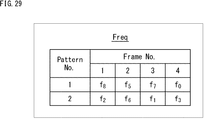
- FIG. 29 is a diagram showing an example of a frequency hopping pattern.
- the frequency hopping pattern indicates the frequency used for each frame to be repeatedly transmitted.
- the number of frequency hopping patterns is an integer of the number of usable frequencies divided by the number of repeated transmissions.
- the hopping pattern of the definable frequency is 2 patterns.
- frequencies f 8 , f 5 , f 7 , and f 0 are used for transmission of frames of frame numbers 1 to 4, respectively.
- frequencies f 2 , f 6 , f 1 , and f 3 are used for transmission of frames of frame numbers 1 to 4, respectively.
- FIG. 30 is a diagram showing an example of a sign hopping pattern.
- the sign hopping pattern indicates a combination of Preamble / SYNC used to generate each frame to be repeatedly transmitted and an initial value used to generate a scramble pattern.
- the reference numerals are fixed, but are not limited to the example of FIG.
- the hopping pattern of the code is composed of one pattern.
- reference numerals C 1 , code C 1 , code C 1 , and code C 1 are used for transmission of frames of frame numbers 1 to 4, respectively.
- V 1 , V 2 , V 3 , and V 4 are used as the values 1 to 4, respectively.
- FIG. 31 is a diagram showing a detection frame list in the communication device 112.
- the radio resources of the detected frames of entries 1 to 7 are registered.
- entry 1 information on a radio resource whose time is T'+ T 1 , whose frequency is f 5 , and whose code is C 1 is registered.
- entry 2 information on a radio resource whose time is T'+ 2T 1 , whose frequency is f 2 , and whose code is C 1 is registered.
- entry 3 information on a radio resource having a time of T'+ 2T 1 , a frequency of f 7 , and a code of C 1 is registered.
- entry 4 information on a radio resource whose time is T'+ 3T 1 , whose frequency is f 0 , and whose code is C 1 is registered.
- FIG. 32 is a diagram showing how the communication device 12 performs DL transmission after identifying the same frame from the detected frames.
- the frames of entries 1 to 7 registered in the detection frame list of FIG. 31 are assigned entry numbers and are shown at positions of frequencies corresponding to each in the order of detection time. Further, on the right side of the DL repeat transmission start time, frames F1 to F4 to be DL transmitted are shown at their respective frequencies in the order of their respective transmission times. Further, the respective codes are also shown in the frames of entries 1 to 7 and the frames F1 to F4 transmitted by DL.
- the above equations (1) and (2) are shared between the user terminal 111 and the communication device 112 in order to determine the wireless resource used for DL communication.
- the user terminal 111 and the communication device 112 have a pattern number 2 (f2) used for repeated transmission of DL communication shown in FIG. 32 according to the equation (1) and the frequency hopping pattern (FIG. 29).
- F6, f1, f3) (Fig. 29) are calculated respectively.
- the user terminal 111 and the communication device 112 calculate the start time (T'+ ⁇ t) of repeated transmission of DL communication by the equation (2), respectively.
- the user terminal 111 can receive the DL frame.
- the processing of the entire wireless communication system 101 is the same processing as the processing described above with reference to FIG.
- the process of the user terminal 111 is also the same process as the process described above in the third embodiment.
- the processing of the communication device 112 is the same processing as the processing described above in the third embodiment, except for the following processing for specifying the same frame.
- step S312 the same frame identification unit 147 extracts a pattern (frequency) and a frame number that match the frequency of the entry of interest.
- step S314 the same frame identification unit 147 extracts a pattern (code) in which the frame number F and the code of the entry of interest match.
- steps S315 to S321 in FIG. 33 are the same processes as steps S255 to S261 in FIG. 25, the description thereof will be omitted.
- a frequency pattern is used in which the frame numbers to be repeatedly transmitted are uniquely determined based on the frequency.
- the fifth embodiment it is possible to determine the number of the detected frame based on the combination of the frequency and the code among the radio resources.
- the configuration of the wireless communication system 101, the configuration of the user terminal 111, and the configuration of the communication device 112 of the fifth embodiment are the same as those of the third embodiment, the configuration of the third embodiment described above Descriptions that overlap with the description will be omitted as appropriate.
- a hopping pattern is defined for each frequency, time, and code.
- FIG. 34 is a diagram showing an example of a time hopping pattern.
- the time hopping pattern is composed of one pattern.
- transmission interval 0 transmission interval T 1 , transmission interval T 1 , and transmission interval T 1 are used for transmission of frames of frame numbers 1 to 4, respectively.
- FIG. 35 is a diagram showing an example of a frequency hopping pattern.
- the hopping pattern of the definable frequency is 4 patterns.
- frequencies f 8 , f 5 , f 7 , and f 0 are used for transmission of frames of frame numbers 1 to 4, respectively.
- frequencies f 2 , f 6 , f 1 , and f 3 are used for transmission of frames of frame numbers 1 to 4, respectively.
- frequencies f 5 , f 2 , f 3 , and f 7 are used for transmission of frames of frame numbers 1 to 4, respectively.
- frequencies f 6 , f 8 , f 0 , and f 1 are used for transmission of frames of frame numbers 1 to 4, respectively.
- FIG. 36 is a diagram showing an example of a sign hopping pattern.
- entry 1 information on a radio resource whose time is T'+ T 1 , whose frequency is f 5 , and whose code is C 2 is registered.
- entry 2 information on a radio resource whose time is T'+ 2T 1 , whose frequency is f 2 , and whose code is C 1 is registered.
- entry 3 information on a radio resource having a time of T'+ 2T 1 , a frequency of f 7 , and a code of C 1 is registered.
- entry 4 information on a radio resource whose time is T'+ 3T 1 , whose frequency is f 0 , and whose code is C 2 is registered.
- FIG. 38 is a diagram showing a state in which the communication device 112 identifies the same frame from the detected frames and then performs DL transmission.
- the frames of entries 1 to 7 registered in the detection frame list of FIG. 37 are assigned entry numbers and are shown at positions of frequencies corresponding to each in the order of detection time. Further, on the right side of the DL repeat transmission start time, frames F1 to F4 to be DL transmitted are shown at their respective frequencies in the order of their respective transmission times. Further, the respective codes are also shown in the frames of entries 1 to 7 and the frames F1 to F4 transmitted by DL.
- the start time (T') repeatedly transmitted as UL communication and the DL communication can also be calculated correctly.
- the above equations (1) and (2) are shared between the user terminal 111 and the communication device 112 in order to determine the wireless resource used for DL communication.
- the user terminal 111 and the communication device 112 have a pattern number 4 (f6) used for repeated transmission of DL communication shown in FIG. 38 according to the equation (1) and the frequency hopping pattern (FIG. 35).
- F8, f0, f1) (Fig. 35) are calculated respectively.
- the user terminal 111 and the communication device 112 calculate the start time (T'+ ⁇ t) of repeated transmission of DL communication by the equation (2), respectively. Therefore, since the wireless resource used for DL communication calculated by the user terminal 111 and the wireless resource used for DL communication calculated by the communication device 112 match, the user terminal 111 can receive the DL frame.
- a frequency hopping pattern and a code hopping pattern are used in which the frame numbers to be repeatedly transmitted are uniquely determined based on the combination of the frequency and the code. ..
- the receiving side uniquely determines the number of the detected frame, it is possible to correctly identify the same frame by performing pattern matching only once for the frame of interest.
- FIG. 39 is a flowchart illustrating another example of the same frame identification process in step S235 of FIG. 24.
- step S351 the same frame identification unit 147 adds a noteworthy entry to the same frame list.
- step S352 the same frame identification unit 147 extracts candidates for patterns (codes) and frame numbers that match the codes of the entry of interest.
- step S353 the same frame identification unit 147 extracts a pattern (frequency) and a frame number in which the frequency of the frame number candidate and the frequency of the attention entry match.
- step S354 the same frame identification unit 147 sets a frame number in F.
- the same frame can be specified correctly.
- the pattern that determines the wireless resources used for UL communication can be correctly specified, the wireless resources used for DL communication calculated by the user terminal and the base station match, and the user terminal receives the DL frame. It will be possible.
- FIG. 40 is a block diagram showing a configuration example of computer hardware that executes the above-mentioned series of processes programmatically.
- An input / output interface 305 is further connected to the bus 304.
- An input unit 306 including a keyboard and a mouse, and an output unit 307 including a display and a speaker are connected to the input / output interface 305.
- the input / output interface 305 is connected to a storage unit 308 made of a hard disk or a non-volatile memory, a communication unit 309 made of a network interface or the like, and a drive 310 for driving the removable media 311.
- the CPU 301 loads the program stored in the storage unit 308 into the RAM 303 via the input / output interface 305 and the bus 304 and executes the program, thereby executing the series of processes described above. Is done.
- the program executed by the CPU 301 is recorded on the removable media 311 or provided via a wired or wireless transmission medium such as a local area network, the Internet, or digital broadcasting, and installed in the storage unit 308.
- the program executed by the computer may be a program that is processed in chronological order in the order described in this specification, or may be a program that is processed in parallel or at a necessary timing such as when a call is made. It may be a program in which processing is performed.
- the system means a set of a plurality of components (devices, modules (parts), etc.), and it does not matter whether all the components are in the same housing. Therefore, a plurality of devices housed in separate housings and connected via a network, and a device in which a plurality of modules are housed in one housing are both systems. ..
- this technology can have a cloud computing configuration in which one function is shared by a plurality of devices via a network and processed jointly.
- each step described in the above flowchart can be executed by one device or shared by a plurality of devices.
- one step includes a plurality of processes
- the plurality of processes included in the one step can be executed by one device or shared by a plurality of devices.
- the present technology can also have the following configurations.
- the first radio resource consisting of the frequency for transmitting the same frame, which is a frame of the same data, the code of the same frame, and the time for transmitting the same frame, is the frame number of the same frame, the frequency, and the code.
- a radio resource determination unit that determines based on pattern information indicating a unique relationship with at least one of them,
- a communication device including a transmission unit that repeatedly transmits the same frame using the first radio resource.
- the radio resource determination unit determines the first radio resource based on the pattern information indicating a unique relationship between the frame number and the frequency.
- the radio resource determining unit determines the first radio resource based on the pattern information indicating a unique relationship between the frame number, the frequency, and the combination of the reference numerals. .. (5) The communication device according to any one of (1) to (4) above, wherein the radio resource determination unit determines a second radio resource required for receiving the same frame based on the first radio resource.
- the first radio resource consisting of the frequency for transmitting the same frame which is a frame of the same data, the code of the same frame, and the time for transmitting the same frame, is the frame number of the same frame, the frequency, and the code. Determined based on pattern information showing a unique relationship with at least one of them A communication method in which the same frame is repeatedly transmitted using the first radio resource.
- a frame detection unit that detects the data frame transmitted by using a radio resource consisting of a frequency for transmitting the data frame, a code of the data frame, and a time for transmitting the data frame.
- a first radio resource determined based on pattern information indicating a unique relationship between the frame number of the same frame, which is a frame of the same data, and at least one of the frequency and the code is obtained.
- a frame specifying unit that specifies the same frame transmitted by using the same frame based on the pattern information
- the same frame is transmitted using the first radio resource determined based on the pattern information indicating the unique relationship between the frame number and the combination of the frequency and the code in (8).
- the communication device described. (12) The communication device according to any one of (8) to (11), further comprising a radio resource determination unit that determines a second radio resource used for transmission of the same frame based on the first radio resource. (13) The communication device according to (12), further comprising a transmission unit that repeatedly transmits the same frame using the second radio resource.
- Communication device The data frame transmitted is detected using a radio resource consisting of the frequency at which the data frame is transmitted, the code of the data frame, and the time at which the data frame is transmitted.
- a first radio resource determined based on pattern information indicating a unique relationship between the frame number of the same frame, which is a frame of the same data, and at least one of the frequency and the code, is obtained.
- the same frame transmitted by using is specified based on the pattern information, and the same frame is specified.
- 101 wireless communication system 111-1 to 111-3, 111 user terminal, 112 communication device, 121 wireless communication unit, 122 wireless control unit, 123 frame generation unit, 124 sensor, 125 wireless resource determination unit, 126 storage unit, 127 Frame detection unit, 128 frame demodulation unit, 141 wireless communication unit, 142 wireless control unit, 143 frame generation unit, 144 wireless resource determination unit, 145 storage unit, 146 frame detection unit, 147 same frame identification unit, 148 frame demodulation unit.
Abstract
本技術は、同一フレームを正しく特定することができるようにする通信装置および方法に関する。 通信装置は、同一データのフレームである同一フレームを送信する周波数、同一フレームの符号、および同一フレームを送信する時刻からなる第1の無線リソースを、同一フレームのフレーム番号と、周波数および符号のうち少なくとも1つとの一意の関係を示すパターン情報に基づいて決定し、第1の無線リソースを用いて、同一フレームを繰り返し送信する。本技術は、無線通信システムに適用することができる。
Description
本技術は、通信装置および方法に関し、特に、同一フレームを正しく特定することができるようにした通信装置および方法に関する。
人または物にセンサ端末を付与し、センサ端末から取得された情報を定期的に無線通信で送信するIoT(Internet of Things)用の無線通信システムがある。IoT用の無線通信システムを利用することにより、新たなサービスの創出が可能になる。例えば、GPS付きのセンサ端末を高齢者または子どもに装着し、センサデータである位置情報を定期的に送信することで、見守りサービスが実現可能となる。このようなIoT用の無線通信システムにおいては、長距離伝送や低消費電力化が要求される。
長距離伝送を実現する方法として、受信信号を合成する方法が考えられる。送信端末が同一フレームを繰り返し送信し、受信端末で受信信号を合成することで、S/Nを高くすることが可能となり、結果として長距離伝送が可能となる。
送信端末が同一フレームを繰り返し送信し、受信端末で受信信号を合成するためには、受信端末が、同一フレームを特定する必要がある。
同一フレームを特定する方法として、ホッピングパターンに基づいて無線リソース(無線資源)を選択して送信する方法が一般的である。
例えば、特許文献1に記載の技術では、時刻同期および先頭フレームの無線リソースの情報の通知と、既知のホッピングパターンとに基づいて、繰り返し送信されるフレームの無線リソースを一意に決めることにより、同一フレームの特定を可能としている。
しかしながら、時刻同期のためのビーコン受信や、先頭フレームの無線リソースの情報を通知するための制御シグナリングの送受信は、送信端末の電力を消費するため、望ましくない。
そこで、非同期で、かつ、制御シグナリングなしに、繰り返し送信および合成を行う無線通信システムを考える。まず、送信端末は、ホッピングパターンを選択し、繰り返し送信を開始する。
基地局の装置は、使用可能な全周波数に対し、使用可能な全符号を用いてフレームを検出し、検出したフレームに基づいて、同一フレームを特定する。最も早い検出時刻のフレームを先頭フレームとみなし、検出したフレームに対してホッピングパターンを用いてパターンマッチングを行うことにより、同一フレームは特定される。
しかしながら、干渉などの影響で、基地局の装置が繰り返し送信の先頭フレームを必ずしも検出できるとは限らない。この場合、同一フレームを正しく特定することが困難であった。
本技術はこのような状況に鑑みてなされたものであり、同一フレームを正しく特定することができるようにするものである。
本技術の一側面の通信装置は、同一データのフレームである同一フレームを送信する周波数、前記同一フレームの符号、および前記同一フレームを送信する時刻からなる第1の無線資源を、前記同一フレームのフレーム番号と、前記周波数および前記符号のうち少なくとも1つとの一意の関係を示すパターン情報に基づいて決定する無線資源決定部と、前記第1の無線資源を用いて、前記同一フレームを繰り返し送信する送信部とを備える。
本技術の他の側面の通信装置は、データフレームを送信する周波数、前記データフレームの符号、および前記データフレームを送信する時刻からなる無線資源を用いて送信されてくる前記データフレームを検出するフレーム検出部と、検出した前記データフレームから、同一データのフレームである同一フレームのフレーム番号と、前記周波数および前記符号のうち少なくとも1つとの一意の関係を示すパターン情報に基づいて決定された第1の無線資源を用いて送信されてくる前記同一フレームを、前記パターン情報に基づいて特定するフレーム特定部と、前記同一フレームを合成して、復調する復調部とを備える。
本技術の一側面においては、同一データのフレームである同一フレームを送信する周波数、前記同一フレームの符号、および前記同一フレームを送信する時刻からなる第1の無線資源が、前記同一フレームのフレーム番号と、前記周波数および前記符号のうち少なくとも1つとの一意の関係を示すパターン情報に基づいて決定される。そして、前記第1の無線資源を用いて、前記同一フレームが繰り返し送信される。
本技術の他の側面においては、データフレームを送信する周波数、前記データフレームの符号、および前記データフレームを送信する時刻からなる無線資源を用いて送信されてくる前記データフレームが検出される。そして、検出した前記データフレームから、同一データのフレームである同一フレームのフレーム番号と、前記周波数および前記符号のうち少なくとも1つとの一意の関係を示すパターン情報に基づいて決定された第1の無線資源を用いて送信されてくる前記同一フレームが、前記パターン情報に基づいて特定され、前記同一フレームが合成されて、復調される。
以下、本技術を実施するための形態について説明する。説明は以下の順序で行う。
1.第1の実施の形態(制御シグナリングありの例)
2.第2の実施の形態(制御シグナリングなしの例)
3.第3の実施の形態(フレーム番号を符号に基づいて特定する例)
4.第4の実施の形態(フレーム番号を周波数に基づいて特定する例)
5.第5の実施の形態(フレーム番号を周波数と符号の組み合わせに基づいて特定する例)
6.その他
1.第1の実施の形態(制御シグナリングありの例)
2.第2の実施の形態(制御シグナリングなしの例)
3.第3の実施の形態(フレーム番号を符号に基づいて特定する例)
4.第4の実施の形態(フレーム番号を周波数に基づいて特定する例)
5.第5の実施の形態(フレーム番号を周波数と符号の組み合わせに基づいて特定する例)
6.その他
<1.第1の実施の形態(制御シグナリングありの例)>
<無線通信システムの構成例>
図1は、本技術の第1の実施の形態に係る無線通信システムの構成例を示す図である。
<無線通信システムの構成例>
図1は、本技術の第1の実施の形態に係る無線通信システムの構成例を示す図である。
図1の無線通信システム1は、ユーザ端末11-1乃至11-3、および通信装置12が、無線通信により接続されることによって構成される。
ユーザ端末11-1乃至11-3と通信装置12との間の無線通信は、ユーザ端末11-1乃至11-3から通信装置12へのUL(UP LINK)通信と、通信装置12からユーザ端末11-1乃至11-3へのDL(DOWN LINK)通信とからなる双方向通信とする。
ユーザ端末11-1乃至11-Nは、1つ、または複数のセンサを備えるIoT(Internet of Things)デバイスである。
以下、適宜、ユーザ端末11-1乃至11-3をそれぞれ区別する必要がない場合、まとめてユーザ端末11と称する。
ユーザ端末11は、UL通信として、例えば、測定対象の測定を行い、測定結果を表すセンサデータを含むデータフレームを通信装置12に送信する。
図1の場合、ユーザ端末11と通信装置12は、予め時刻同期している。ユーザ端末11は、ホッピングパターンを用いて、無線リソース(無線資源)を選択する。ユーザ端末11は、選択した無線リソースを用いて、同一のデータフレームである同一フレームを、例えば4回繰り返し送信する。
ホッピングパターンは、ユーザ端末11と通信装置12とでパターン情報として共有されている。ホッピングパターンは、無線リソースとフレーム番号との組み合わせを示す1または複数のパターンからなる。無線リソースは、周波数、時刻、および符号からなる。周波数とは、フレームを送信する周波数である。時刻とは、フレームを送信する送信時間間隔(送信間隔)である。符号とは、フレームの符号に関する情報であり、本技術の場合、符号の生成に用いられる初期値である。
ユーザ端末11は、データフレームの送信に先立ち、制御シグナリングを含む制御フレームを通信装置12に送信する。制御フレームは、先頭フレームの無線リソースの情報を含む。
また、ユーザ端末11は、UL通信で用いた無線リソースに基づいて、DL通信の無線リソースを決定する。ユーザ端末11は、DL通信として、通信装置12から送信されてくるデータフレームを受信する。
通信装置12は、基地局を構成する。通信装置12は、ユーザ端末11から送信されてくる制御フレームを受信した後、フレーム検出を行う。通信装置12は、制御フレームを受信することで得られる先頭フレームの無線リソースの情報と既知のホッピングパターンとを用いて、検出したフレームの中から同一フレームを特定する。通信装置12は、特定した同一フレームを合成して、復調を行う。
また、通信装置12は、UL通信で用いた無線リソースに基づいて、DL通信の無線リソースを決定し、DL通信として、データフレームをユーザ端末11に送信する。
<通信装置の構成例>
図2は、通信装置12の構成例を示すブロック図である。
図2は、通信装置12の構成例を示すブロック図である。
通信装置12は、フレーム検出部31、検出フレームリスト記憶部32、先頭フレーム情報記憶部33、ホッピングパターン記憶部34、同一フレーム特定部35、受信信号合成部36、および復調部37から構成される。
受信信号は、フレーム検出部31および受信信号合成部36に供給される。
フレーム検出部31は、受信信号と既知パターンの相関を算出し、算出後の相関値が所定の閾値を超える場合にフレームを検出したと判定する。フレーム検出部31は、検出したフレームの無線リソース(周波数、時刻、符号)の情報を検出フレームリスト記憶部32に追加する。検出フレームリスト記憶部32には、検出したフレームの無線リソースの情報が記憶される。
先頭フレーム情報記憶部33には、データフレームの送信前に、先頭フレームの無線リソースの情報が制御シグナリングにより通知され、記憶されている。ホッピングパターン記憶部34には、ホッピングパターンが記憶されている。
同一フレーム特定部35は、検出したフレームの中から、繰り返し送信された同一フレームを特定する。同一フレーム特定部35は、先頭フレームの無線リソースの情報とホッピングパターンに基づいて、繰り返し送信される同一フレームに用いられる無線リソースを一意に決めることで、同一フレームを特定する。
受信信号合成部36は、同一フレームであると同一フレーム特定部35により特定された無線リソースの受信信号を、受信した受信信号から切り出して合成する。復調部37は、受信信号合成部36により合成された信号を復調する。
以上のように、図2の通信装置12においては、時刻同期、先頭フレームの無線リソースの情報の取得、および既知のホッピングパターンに基づいて、繰り返し送信される同一フレームに用いられる無線リソースが一意に決まる。これにより、同一フレームの特定が可能となる。
しかしながら、時刻同期のためのビーコン送信や、先頭フレームの無線リソースの情報を通知するための制御シグナリングの送受信は、ユーザ端末11の電力を消費してしまうため、望ましくない。
<2.第2の実施の形態(制御シグナリングなしの例)>
そこで、本技術の第2の実施の形態として、非同期で、かつ、制御シグナリングなしに、繰り返し送信および合成を行うシステムについて説明する。なお、図1の無線通信システム1を再度参照して説明する。
そこで、本技術の第2の実施の形態として、非同期で、かつ、制御シグナリングなしに、繰り返し送信および合成を行うシステムについて説明する。なお、図1の無線通信システム1を再度参照して説明する。
ユーザ端末11は、無線通信システム1でパターン情報として予め共有されているホッピングパターンから、任意のパターンを選択し、任意の時刻に同一フレームを繰り返し送信する。
<ホッピングパターンの例>
図3は、周波数のホッピングパターンの例を示す図である。
図3は、周波数のホッピングパターンの例を示す図である。
周波数のホッピングパターンは、繰り返し送信する各フレームに用いられる周波数を定義している。図3には、繰り返し送信回数が4回、使用可能な周波数の数が9つとして組み合わされた複数のパターンからなるホッピングパターンが示されている。
パターン番号1のパターンが選択された場合、フレーム番号1乃至4のフレームの送信には、それぞれ、周波数f8、f5、f7、f0が用いられる。パターン番号2のパターンが選択された場合、フレーム番号1乃至4のフレームの送信には、それぞれ、周波数f7、f8、f0、f5が用いられる。パターン番号3のパターンが選択された場合、フレーム番号1乃至4のフレームの送信には、それぞれ、周波数f6、f3、f8、f2が用いられる。パターン番号4のパターンが選択された場合、フレーム番号1乃至4のフレームの送信には、それぞれ、周波数f5、f4、f6、f8が用いられる。
パターン番号5のパターンが選択された場合、フレーム番号1乃至4のフレームの送信には、それぞれ、周波数f4、f1、f2、f7が用いられる。パターン番号6のパターンが選択された場合、フレーム番号1乃至4のフレームの送信には、それぞれ、周波数f3、f0、f5、f1が用いられる。パターン番号7のパターンが選択された場合、フレーム番号1乃至4のフレームの送信には、それぞれ、周波数f2、f6、f1、f3が用いられる。
パターン番号8のパターンが選択された場合、フレーム番号1乃至4のフレームの送信には、それぞれ、周波数f1、f7、f4、f6が用いられる。パターン番号9のパターンが選択された場合、フレーム番号1乃至4のフレームの送信には、それぞれ、周波数f0、f2、f3、f4が用いられる。
以上のように、パターン毎に、フレーム番号と周波数の組み合わせが異なっている。
例えば、ユーザ端末11がパターン番号1のパターンを選択した場合、同一フレームは、周波数f8、f5、f7、f0が用いられて送信される。ここでは、説明の便宜上、周波数以外の無線リソースである時刻と符号に関しては固定とする。ただし、時刻と符号についてもホッピングパターンを定義して、可変とするようにしてもよい。また、ここでいう時刻とは、上述したように、同一フレームを送信する送信間隔のことをいう。符号は、Preamble/SYNCとスクランブルパターン(符号)の生成に用いる初期値を表す。
また、無線通信システム1においては、このホッピングパターンを用いることで、UL通信に用いた無線リソースに基づいて、DL通信に用いる無線リソースが決定される。例えば、DL通信は、繰り返し送信する先頭フレームの送信開始時刻からΔt後に開始される。DL通信には、UL通信に用いられたパターン番号1+ΔPのパターンが示す無線リソースが用いられる。
<ユーザ端末が用いる無線リソース>
図4は、ユーザ端末11が用いる無線リソースの例を示す図である。
図4は、ユーザ端末11が用いる無線リソースの例を示す図である。
図4において、縦軸は、周波数を表し、横軸は、時間を表す。また、矩形は、フレームを表す。以降の図についても同様である。
ユーザ端末11は、UL通信のホッピングパターンとして、パターン番号1のパターンを用いる。したがって、ユーザ端末11は、UL通信として、フレームF1を周波数f8を用いて送信し、フレームF2を周波数f5を用いて送信し、フレームF3を周波数f7を用いて送信し、フレームF4を周波数f0を用いて送信する。
DL通信には、UL通信として繰り返し送信する先頭フレームF1の送信開始時刻からΔt後にUL通信で用いられたパターン番号1+ΔP(=3)であるパターン番号4のパターンが示す無線リソースが用いられる。
したがって、ユーザ端末11は、DL通信として、周波数f5を用いて送信されてきたフレームF1を受信し、周波数f4を用いて送信されてきたフレームF2を受信することができる。次いで、ユーザ端末11は、周波数f6を用いて送信されてきたフレームF3を受信し、周波数f8を用いて送信されてきたフレームF4を受信することができる。
以上のように、UL通信で用いた無線リソースからDL通信で用いられる無線リソースが一意に決まる。したがって、ユーザ端末11は、受信処理を行う必要がある時間のみ、該当する周波数に対し、該当する符号を用いて受信処理を行うだけでよい。受信処理は、フレーム検出、合成、復調を含む処理である。
<通信装置の構成例>
図5は、通信装置12の構成例を示すブロック図である。
図5は、通信装置12の構成例を示すブロック図である。
図5においては、無線通信システム1が、非同期で、かつ、制御シグナリングなしに、繰り返し送信および合成を行うシステムである場合の通信装置の構成例が示されている。
通信装置12は、フレーム検出部51、検出フレームリスト記憶部32、ホッピングパターン記憶部34、同一フレーム特定部52、受信信号合成部36、および復調部37から構成される。図5に示す構成のうち、図2を参照して説明した構成と同じ構成には同じ符号を付してある。重複する説明については適宜省略する。
受信信号は、フレーム検出部51および受信信号合成部36に供給される。
フレーム検出部51は、ユーザ端末11がどの無線リソースを使用してフレームを送信してくるのかわからない。フレーム検出部51は、常時、使用可能な全周波数に対し、使用可能な全符号を用いてフレームを検出する。
同一フレーム特定部52は、検出したフレームの中から、繰り返し送信された同一フレームを特定する。具体的には、同一フレーム特定部52は、検出フレームリスト記憶部32を参照して、検出時刻が早い順に、注目するフレームである注目フレームを決定する。
同一フレーム特定部52は、注目フレームを先頭フレームとみなし、先頭フレームの周波数とホッピングパターンに基づいて、送信に用いられたホッピングパターンを推定する。同一フレーム特定部52においては、先頭フレームの周波数と、ホッピングパターンにおけるフレーム番号1の周波数とが一致するパターンが、送信に用いられたホッピングパターンであると推定される。同一フレーム特定部52は、推定したホッピングパターンが示す周波数と時刻に基づいて、検出したフレームの中から、2フレーム目以降のフレームを特定する。
受信信号合成部36は、同一フレーム特定部52により特定された無線リソースで送信されてきた受信信号を、受信した受信信号から切り出して合成する。復調部37は、受信信号合成部36により合成された信号を復調する。
復調に成功した場合、通信装置12は、注目フレームの検出時刻と推定したホッピングパターンに基づいて、DL通信に用いる無線リソースを、ユーザ端末11と同様の方法で決定する。通信装置12は、決定した無線リソースを用いてフレームを送信する。
<先頭フレームが検出された場合の例>
図6は、通信装置12が用いる無線リソースの例を示す図である。
図6は、通信装置12が用いる無線リソースの例を示す図である。
通信装置12では、図6に示されるように、UL通信として、フレームB:F1、フレームB:F2、フレームC:F1、フレームB:F3、フレームC:F2、フレームB:F4、フレームC:F3、フレームC:F4が順に検出される。
フレームB:F1、フレームB:F2、フレームB:F3、フレームC:F4は、受信対象のユーザ端末11から送信されてきたフレームである。フレームC:F1、フレームC:F2、フレームC:F3、フレームC:F4は、受信対象のユーザ端末11とは異なるユーザ端末11から送信されてきたフレームである。
通信装置12は、検出時刻が最も早いフレームB:F1を注目フレームに決定する。通信装置12は、注目フレームを先頭フレームとみなす。通信装置12は、先頭フレームであるフレームB:F1の周波数f8と同じ周波数がフレーム番号1に用いられているホッピングパターン(図3のパターン番号1のパターン)を、送信に用いられたホッピングパターンであると推定する。
通信装置12は、検出したフレームに対して、パターン番号1のパターン(周波数f8、f5、f7、f0)を用いてパターンマッチングを行う。通信装置12は、パターンマッチングの結果、周波数f5、周波数f7、周波数f0を用いて受信されたフレームB:F2、フレームB:F3、フレームB:F4を、同一フレームであると特定する。
なお、フレームB:F1の検出時刻とフレームB:F2の検出時刻との間隔、フレームB:F2の検出時刻とフレームB:F2の検出時刻との間隔、フレームB:F3の検出時刻とフレームB:F4の検出時刻との間隔は、各送信間隔に許容誤差が加減された時刻間隔である。
また、通信装置12は、DL通信の送信開始時刻を、繰り返し送信する先頭フレームB:F1の送信開始時刻からΔt後に決定する。通信装置12は、DL通信の周波数を、UL通信で用いられたパターン番号1+ΔP(=3)のパターン番号4のパターンの周波数に決定する。通信装置12は、DL通信として、決定したパターン番号4のパターンが示す無線リソース(周波数f5、f4、f6、f8)を用いて、フレームB:F1、フレームB:F2、フレームB:F3、フレームB:F4を受信することができる。
以上のように、検出時刻が最も早いフレームを先頭フレームとみなし、検出したフレームに対しホッピングパターンを用いてパターンマッチングを行うことで、繰り返し送信された同一フレームを特定することができる。
しかしながら、干渉などの影響で、通信装置12が繰り返し送信の先頭フレームを必ずしも検出できるとは限らない。
<先頭フレームの検出に失敗した場合の例>
図7は、先頭フレームの検出に失敗した場合の通信装置12が用いる無線リソースの様子を示す図である。
図7は、先頭フレームの検出に失敗した場合の通信装置12が用いる無線リソースの様子を示す図である。
先頭フレームのフレームB:F1の検出に失敗した場合、通信装置12は、検出時刻が最も早いフレームB:F2を注目フレームに決定する。通信装置12は、注目フレームを先頭フレームとみなす。通信装置12は、先頭フレームであるフレームB:F2の周波数f8と同じ周波数がフレーム番号1に用いられているホッピングパターン(図3のパターン番号4)を、送信に用いられたホッピングパターンであると推定してしまう。
通信装置12は、検出されたフレームに対して、パターン番号4のパターン(周波数f5、f4、f6、f8)を用いてパターンマッチングを行う。パターンマッチングの結果、周波数f4を用いて受信されたフレームは検出されていない。周波数f6を用いて受信されたフレームは、フレームC:F4である。周波数f8を用いて受信されたフレームは検出されていない。したがって、通信装置12は、周波数f6を用いて受信されたフレームであるフレームC:F4を、同一フレームであると特定する。
すなわち、パターンマッチングの結果、通信装置12は、異なるユーザ端末11から送信されてきたフレームC:F4を、同一フレームとして誤って特定し、合成してしまう。
また、通信装置12は、DL通信の送信開始時刻を、繰り返し送信する先頭フレームB:F2の送信開始時刻からΔt後に決定してしまう。通信装置12は、DL通信の周波数を、UL通信で用いられたパターン番号4+ΔP(=3)であるパターン番号7のパターンを決定してしまう。パターン番号7のパターンは、図7のDL通信のフレームB:F1乃至B:F4に示されるように、周波数f2、f6、f1、f3である。
しかしながら、実際の先頭フレームは、フレームB:F1である。先頭フレームが、フレームB:F1である場合、DL通信の送信開始時刻は、図6に示されたように、繰り返し送信する先頭フレームB:F1の送信開始時刻からΔt後である。また、先頭フレームがフレームB:F1である場合、実際にDL通信で用いられるホッピングパターンは、図6のDL通信のフレームB:F1乃至B:F4に示されたように、パターン番号4のパターン(周波数f5、f4、f6、f8)である。
したがって、通信装置12とユーザ端末11で用いる無線リソースが一致せず、ユーザ端末11は、DL通信用のフレームであるDLフレームを受信できない。
そこで、検出時刻が最も早いフレームを先頭フレームとしてみなすだけでなく、フレーム番号2のフレーム乃至フレーム番号(繰り返し送信回数-1)のフレームを、先頭フレームである可能性のあるフレームとみなして、同一フレームの特定を行う必要がある。
しかしながら、この方法では、同一フレームの特定を行うパターンが増加してしまう。その結果、同一フレーム特定の探索時間の増加による受信処理時間の増加や、復調する同一フレームの組み合わせ数の増加による基地局の演算量の増加が懸念される。
そこで、本技術においては、繰り返し送信するフレーム番号が符号に基づいて一意に決まるように限定をした符号のホッピングパターンが用いられる。これにより、受信側で、検出したフレームが、何フレーム目のフレームであるかを一意に決めることができる。
<3.第3の実施の形態(フレーム番号を符号に基づいて特定する例)>
<無線通信システムの構成例>
図8は、本技術の第3の実施の形態に係る無線通信システムの構成例を示すブロック図である。
<無線通信システムの構成例>
図8は、本技術の第3の実施の形態に係る無線通信システムの構成例を示すブロック図である。
図8の無線通信システム101は、ユーザ端末111-1乃至111-3、および通信装置112が、無線通信により接続されることによって構成される。
ユーザ端末111-1乃至111-3と通信装置112との間の無線通信は、ユーザ端末111-1乃至111-3から通信装置112へのUL通信と、通信装置112からユーザ端末111-1乃至111-3へのDL通信とからなる双方向通信とする。
ユーザ端末111-1乃至111-Nは、1つ、または複数のセンサを備えるIoTデバイスである。ユーザ端末111-1乃至111-Nは、例えば、カメラ、マイクロフォン、加速度センサ、角速度センサ、地磁気センサ、照度センサ、温度センサ、湿度センサ、水分センサ、光センサ、気圧センサ、および測位センサなどのうち、少なくとも1つのセンサを備える。
以下、適宜、ユーザ端末111-1乃至111-3をそれぞれ区別する必要がない場合、まとめてユーザ端末111と称する。
無線通信システム101において、ユーザ端末111と通信装置112は、周波数のホッピングパターン、符号のホッピングパターン、および時刻のホッピングパターンを共有している。周波数のホッピングパターン、符号のホッピングパターン、および時刻のホッピングパターンは、受信側においてフレーム番号が符号に基づいて特定されるように構成されている。
ユーザ端末111は、UL通信として、例えば、測定対象の測定を行い、測定結果を表すセンサデータを含むデータフレームを通信装置112に送信する。
ユーザ端末111は、周波数、符号、および時刻の各ホッピングパターンを用いて無線リソースを選択する。ユーザ端末111は、選択した無線リソースを用いて、同一のデータフレームである同一フレームを、例えば4回繰り返し送信する。
また、ユーザ端末111は、UL通信で用いた無線リソースに基づいて、DL通信の無線リソースを決定する。ユーザ端末111は、DL通信として、DL通信の無線リソースを用いて、通信装置112から送信されてくる同一フレームを受信する。
通信装置112は、基地局を構成する。通信装置112は、ユーザ端末111から送信されてくるフレームを検出する。通信装置112は、ホッピングパターンを用いて、検出したフレームの中から同一フレームを特定する。
通信装置112は、検出したフレームのフレーム番号を符号に基づいて特定することで、ホッピングパターンを決定する。通信装置112は、検出したフレームと決定したホッピングパターンとのパターンマッチングにより、同一フレームを特定する。通信装置112は、特定した同一フレームを合成して、復調を行う。
また、通信装置112は、UL通信で用いた無線リソースに基づいて、DL通信の無線リソースを決定し、DL通信として、DL通信の無線リソースを用いて、データフレームをユーザ端末111に送信する。
以上のように、検出したフレームのフレーム番号が符号に基づいて特定される。これにより、時刻同期や制御フレームを送信することなく、同一フレームを正確に特定することができる。
<ユーザ端末の構成例>
図9は、ユーザ端末111の構成例を示すブロック図である。
図9は、ユーザ端末111の構成例を示すブロック図である。
ユーザ端末111は、無線通信部121、無線制御部122、フレーム生成部123、センサ124、無線リソース決定部125、記憶部126、フレーム検出部127、およびフレーム復調部128から構成される。
無線通信部121は、通信装置112と、無線信号の送受信を行う。無線通信部121は、無線制御部122から供給される制御信号に従って、フレーム生成部123により生成されたフレームを無線信号に変換し、通信装置112に送信する。
無線通信部121は、無線制御部122から供給される制御信号に従って、通信装置12から送信されてくる電波を受信し、無線信号に変換する。無線通信部121は、変換した無線信号をフレーム検出部127およびフレーム復調部128に出力する。
無線制御部122は、CPU(Central Processing Unit)、ROM(Read Only Memory)、RAM(Random Access Memory)などにより構成される。無線制御部122は、ROMなどに記憶されているプログラムを実行し、無線通信部121を制御する。
無線制御部122は、無線リソース決定部125から供給される送信時刻および送信周波数を用いて、フレーム生成部123から供給されるフレームを送信するよう、無線通信部121を制御する。また、無線制御部122は、必要に応じて、無線リソース決定部125から供給される受信時刻および受信周波数を用いてフレームを受信するよう、無線通信部121を制御する。
フレーム生成部123は、センサ124から供給されるセンサデータを含むデータフレームを生成し、生成したデータフレームを無線制御部122に出力する。データフレームの生成には、無線リソース決定部125から供給される符号が用いられる。
センサ124は、端末外部や内部の情報を測定し、測定結果を表すセンサデータをフレーム生成部123に出力する。
無線リソース決定部125は、記憶部126から取得したホッピングパターンを用いて、各データフレームを送信する無線リソースを決定する。無線リソース決定部125は、決定した符号を初期値として用いて、Preamble/SYNCとスクランブルパターンをそれぞれ生成する。また、無線リソース決定部125は、UL通信に使用した無線リソースに基づいて、DL通信に用いる無線リソースを決定する。
記憶部126は、無線リソースの決定に用いられるホッピングパターンを記憶する。
フレーム検出部127は、フレームを、無線通信部121から供給される受信信号から検出する。具体的には、フレーム検出部127は、広域信号から対象となる周波数の信号を、無線通信部121から供給される受信信号から取り出し、Preamble/SYNCとスクランブルパターンを用いて既知パターンを生成する。
フレーム検出部127は、信号と既知パターンとの相関値を算出し、相関値が一定以上の値となる場合に、フレームを検出したと判定する。フレーム検出部127は、フレームの検出に成功した場合、検出した無線リソースをフレーム復調部128に出力する。
フレーム復調部128は、無線通信部121から供給される受信信号を用いて、フレームを合成し、復調する。具体的には、フレーム復調部128は、フレーム検出部127により検出されたフレーム数分の無線リソースに基づいて、受信信号からフレームに該当する部分の信号を取り出す。
フレーム復調部128は、取り出した信号に対して、無線リソース決定部125から供給されるスクランブルパターンでスクランブルを解除し、スクランブルを解除した信号を合成する。フレーム復調部128は、Payloadを、合成した信号から取り出し、誤り訂正符号の復号処理とCRCを用いた誤り検出処理を行う。フレーム復調部128は、フレームの復調に成功した場合、データを上位層に通知する。
なお、DL通信を行わない場合、ユーザ端末111は、フレーム検出部127およびフレーム復調部128なしに構成されるようにしてもよい。
<通信装置の構成例>
図10は、通信装置112の構成例を示すブロック図である。
図10は、通信装置112の構成例を示すブロック図である。
通信装置112は、無線通信部141、無線制御部142、フレーム生成部143、無線リソース決定部144、記憶部145、フレーム検出部146、同一フレーム特定部147、およびフレーム復調部148から構成される。
無線通信部141は、ユーザ端末111と、無線信号の送受信を行う。無線通信部141は、無線制御部142から供給される制御信号に従って、ユーザ端末111から送信されてくる電波を受信し、無線信号に変換する。無線通信部141は、変換した無線信号をフレーム検出部146およびフレーム復調部148に出力する。
無線通信部141は、無線制御部142から供給される制御信号に従って、フレーム生成部143により生成されたフレームを、無線信号に変換し、ユーザ端末111に送信する。
無線制御部142は、CPU、ROM、RAMなどにより構成される。無線制御部142は、ROMなどに記憶されているプログラムを実行し、無線通信部141を制御する。
無線制御部142は、無線リソース決定部144から供給される受信時刻および受信周波数を用いてフレームを受信するよう、無線通信部141を制御する。また、無線制御部142は、必要に応じて、無線リソース決定部144から供給される送信時刻および送信周波数を用いて、フレーム生成部143から供給されるフレームを送信するよう、無線通信部141を制御する。
フレーム生成部143は、無線リソース決定部144から供給される符号を用いて、通信装置112が送信するデータフレームを生成する。フレーム生成部143は、生成したデータフレームを無線制御部142に出力する。
無線リソース決定部144は、記憶部145から取得したホッピングパターンを用いて、各データフレームを送信する無線リソース(時刻、周波数、符号)を決定する。無線リソース決定部144は、決定した符号を初期値として用いて、Preamble/SYNCとスクランブルパターンをそれぞれ生成する。
また、無線リソース決定部144は、端末のIDとDL送信に用いる無線リソースが登録されるDL送信リストを有している。無線リソース決定部144は、UL通信に使用した無線リソースに基づいて、DL通信に用いる無線リソースを決定する。無線リソース決定部144は、端末のIDとDL送信に用いる無線リソースをDL送信リストに登録する。
無線リソース決定部144は、DL送信リストの無線リソースを抽出し、無線リソースのうちの符号を、フレーム生成部143に出力する。無線リソース決定部144は、無線リソースのうちの周波数と時刻とを、無線制御部142に出力する。
記憶部145は、無線リソースの決定に用いられるホッピングパターンを記憶する。
フレーム検出部146は、フレームを、無線通信部141から供給される受信信号から検出する。フレームの検出方法は、図9のフレーム検出部127におけるフレームの検出方法と同様の検出方法である。
フレーム検出部146は、フレームの検出に成功した場合、検出した無線リソースの情報を、エントリとして、同一フレーム特定部147が有する検出フレームリストに登録する。
同一フレーム特定部147は、検出したフレームの無線リソースが登録される検出フレームリストを有している。同一フレーム特定部147は、検出フレームリストの無線リソースの情報と、記憶部145から取得したホッピングパターンとを用いて、繰り返し送信された同一フレームを、検出したフレームの中から特定する。
同一フレーム特定部147は、同一フレームの特定に成功した場合、特定した同一フレームの無線リソースの情報を、エントリとして、フレーム復調部148が有する同一フレームリストに登録する。
フレーム復調部148は、同一フレームの無線リソースが登録される同一フレームリストを有している。フレーム復調部148は、同一フレームリストにエントリが複数存在する場合、無線通信部121から供給される受信信号を用いて、フレームを合成し、復調する。フレームの合成、復調方法は、図9のフレーム復調部128における合成、復調方法と同様の合成、復調方法である。
フレーム復調部148は、フレームの復調に成功した場合、データを上位層に通知する。また、フレーム復調部148は、フレームの復調に成功した場合、UL通信の無線リソースとして、同一フレームの無線リソースを無線リソース決定部144に出力する。
なお、DL通信を行わない場合、通信装置112は、フレーム生成部143なしに構成されるようにしてもよい。
<フレームの構成例>
図11は、無線通信システム101で送受信されるフレームの構成例を示す図である。
図11は、無線通信システム101で送受信されるフレームの構成例を示す図である。
フレームは、Preamble/SYNCとPayloadのフィールドとで構成される。Payloadは、ID、DATA、CRC(Cyclic Redundancy Check)などのフィールドを有する。
IDには、端末固有の識別子が含まれる。DATAには、センサデータが含まれる。CRCには、IDとDATAに対して算出した値で、受信側で受信成功の判定に使用される値が含まれる。
フレーム生成部123およびフレーム生成部143は、ID、DATA、およびCRCを連結した系列に対して、誤り訂正やInterleaveを行い、Payloadを生成する。
フレーム生成部123およびフレーム生成部143は、PayloadとデータフレームのPreamble/SYNCとを連結した後で、データフレームのスクランブルパターンでビット毎に排他的論理和をとり、データフレーム(Frame)を生成する。
フレームで用いられるPreamble/SYNCとスクランブルパターンは、無線リソース決定部125および無線リソース決定部144において符号(の初期値)から生成されるパターンである。
<ホッピングパターンの例>
次に、無線リソースの生成に用いられるホッピングパターンについて説明する。図7の無線通信システム101では、時刻、周波数、符号毎にホッピングパターンが定義されている。なお、以降の図において、繰り返し送信回数は、4回の例が示される。
次に、無線リソースの生成に用いられるホッピングパターンについて説明する。図7の無線通信システム101では、時刻、周波数、符号毎にホッピングパターンが定義されている。なお、以降の図において、繰り返し送信回数は、4回の例が示される。
<時刻のホッピングパターン>
図12は、時刻のホッピングパターンの例を示す図である。
図12は、時刻のホッピングパターンの例を示す図である。
時刻のホッピングパターンは、各フレームを繰り返し送信する送信間隔を示している。第3の実施の形態の場合、パターン数は1つに限定される。送信間隔の値は特に限定されない。
図12の場合、時刻のホッピングパターンは、1つのパターンで構成される。パターン番号1のパターンが選択された場合、フレーム番号1乃至4のフレームの送信には、それぞれ、送信間隔0、送信間隔T1、送信間隔T1、送信間隔T1が用いられる。
<周波数のホッピングパターン>
図13は、周波数のホッピングパターンの例を示す図である。
図13は、周波数のホッピングパターンの例を示す図である。
周波数のホッピングパターンは、繰り返し送信する各フレームに用いられる周波数を示している。図13には、使用可能な周波数が9つあり、全周波数を万遍なく割り当てるパターンが示されている。周波数のホッピングパターンは、図13の例に限定されない。
パターン番号1のパターンが選択された場合、フレーム番号1乃至4のフレームの送信には、それぞれ、周波数f8、f5、f7、f0が用いられる。パターン番号2のパターンが選択された場合、フレーム番号1乃至4のフレームの送信には、それぞれ、周波数f7、f8、f0、f5が用いられる。パターン番号3のパターンが選択された場合、フレーム番号1乃至4のフレームの送信には、それぞれ、周波数f6、f3、f8、f2が用いられる。パターン番号4のパターンが選択された場合、フレーム番号1乃至4のフレームの送信には、それぞれ、周波数f5、f4、f6、f8が用いられる。
パターン番号5のパターンが選択された場合、フレーム番号1乃至4のフレームの送信には、それぞれ、周波数f4、f1、f2、f7が用いられる。パターン番号6のパターンが選択された場合、フレーム番号1乃至4のフレームの送信には、それぞれ、周波数f3、f0、f5、f1が用いられる。パターン番号7のパターンが選択された場合、フレーム番号1乃至4のフレームの送信には、それぞれ、周波数f2、f6、f1、f3が用いられる。
パターン番号8のパターンが選択された場合、フレーム番号1乃至4のフレームの送信には、それぞれ、周波数f1、f7、f4、f6が用いられる。パターン番号9のパターンが選択された場合、フレーム番号1乃至4のフレームの送信には、それぞれ、周波数f0、f2、f3、f4が用いられる。
<符号のホッピングパターン>
図14は、符号のホッピングパターンの例を示す図である。
図14は、符号のホッピングパターンの例を示す図である。
符号のホッピングパターンは、繰り返し送信する各フレームの生成に用いるPreamble/SYNCとスクランブルパターンとを生成するのに使用される初期値の組み合わせを示す。第3の実施の形態では、繰り返し送信するフレーム番号が、符号に基づいて一意に決まるよう限定する必要がある。パターン数は限定されず、複数のパターンで構成されてもよい。
図14の場合、符号のホッピングパターンは、1つのパターンで構成される。パターン番号1のパターンが選択された場合、フレーム番号1乃至4のフレームの送信には、それぞれ、符号C1、符号C2、符号C3、符号C4が用いられる。
なお、符号C1では、Value1乃至Value4として、それぞれ、V1、V2、V3、V4が用いられる。符号C2では、Value1乃至Value4として、それぞれ、V2、V3、V4、V5が用いられる。符号C3では、Value1乃至Value4として、それぞれ、V3、V4、V1、V2が用いられる。符号C1では、Value1乃至Value4として、それぞれ、V4、V1、V2、V3が用いられる。
<擬似乱数生成器の構成>
図15は、Preamble/SYNC、スクランブルパターンの生成に用いられる擬似乱数生成器としてのゴールド符号生成器の構成例を示す図である。
図15は、Preamble/SYNC、スクランブルパターンの生成に用いられる擬似乱数生成器としてのゴールド符号生成器の構成例を示す図である。
図15のゴールド符号生成器151は、2つのM系列を出力する4つの擬似乱数生成器161-1乃至161-4と2つの排他的論理和(XOR)の演算器171-1および171-2とにより構成される。このゴールド符号生成器151は、無線リソース決定部125および無線リソース決定部144に用いられる。
符号CのValue1が初期値として、擬似乱数生成器161-1に入力される。符号CのValue2が初期値として、擬似乱数生成器161-2に入力される。擬似乱数生成器161-1と擬似乱数生成器161-2は、初期値を入力して、乱数を生成する。擬似乱数生成器161-1から出力される値(乱数)は、演算器171-1に入力される。擬似乱数生成器161-2から出力される値(乱数)は、演算器171-1に入力される。演算器171-1は、擬似乱数生成器161-1および161-2から供給される値を積算することで、Preamble/SYNC(擬似乱数)を得る。このとき、Preamble/SYNCは、フレームのPreamble/SYNC長に一致する長さを得る。
同様に、符号CのValue3が初期値として、擬似乱数生成器161-3に入力される。符号CのValue4が初期値として、擬似乱数生成器161-4に入力される。擬似乱数生成器161-3と擬似乱数生成器161-4は、初期値を入力して、乱数を生成する。擬似乱数生成器161-3から出力される値(乱数)は、演算器171-2に入力される。擬似乱数生成器161-2から出力される値(乱数)は、演算器171-2に入力される。演算器171-2は、擬似乱数生成器161-3および161-4から供給される値を積算することで、スクランブルパターン(擬似乱数)を得る。このとき、スクランブルパターンは、フレーム長に一致する長さを得る。
このように、Preamble/SYNCとスクランブルパターンを生成する場合、Value1乃至Value4がすべて同じ値になる組み合わせ以外、フレーム検出に用いる既知パターンは、異なるパターンとなる。
<第3の実施の形態の効果>
次に、繰り返し送信するフレーム番号が、符号に基づいて一意に決まるように限定をしたホッピングパターン(図12乃至図14)を用いた場合に、受信側で1フレーム目の同一フレームが正しく検出できなかった例について説明する。
次に、繰り返し送信するフレーム番号が、符号に基づいて一意に決まるように限定をしたホッピングパターン(図12乃至図14)を用いた場合に、受信側で1フレーム目の同一フレームが正しく検出できなかった例について説明する。
図16は、通信装置112における検出フレームリストを示す図である。
図16の検出フレームリストには、エントリ1乃至7までの検出されたフレームの無線リソースの情報が登録されている。
エントリ1として、時刻がT’+T1であり、周波数がf5であり、符号がC2である無線リソースの情報が登録されている。エントリ2として、時刻がT’+2T1であり、周波数がf2であり、符号がC1である無線リソースの情報が登録されている。エントリ3として、時刻がT’+2T1であり、周波数がf7であり、符号がC3である無線リソースの情報が登録されている。エントリ4として、時刻がT’+3T1であり、周波数がf0であり、符号がC4である無線リソースの情報が登録されている。
エントリ5として、時刻がT’+3T1であり、周波数がf6であり、符号がC2である無線リソースの情報が登録されている。エントリ6として、時刻がT’+4T1であり、周波数がf1であり、符号がC3である無線リソースの情報が登録されている。エントリ7として、時刻がT’+5T1であり、周波数がf3であり、符号がC4である無線リソースの情報が登録されている。
図17は、通信装置12が、検出したフレームから同一フレームを特定した後、DL送信を行う例を示す図である。
図17には、図16の検出フレームリストに登録されたエントリ1乃至7のフレームが、エントリ番号が付されて、検出時刻順に、それぞれが対応する周波数の位置に示されている。また、DL繰り返し送信開始時刻より右側には、DL送信されるフレームF1乃至F4が、それぞれの周波数で、それぞれの送信時刻順に示されている。さらに、エントリ1乃至7のフレーム、並びにDL送信されるフレームF1乃至F4には、それぞれの符号も示されている。
図17に示されるように、検出フレームリストのエントリ1を注目エントリとして、同一フレーム特定処理を行った場合、検出した符号が(C2)である。したがって、注目フレームの符号は、符号のホッピングパターン(図14)に基づいて、フレーム番号2の符号であることが特定される。
また、注目エントリのフレームを検出した周波数(f5)と周波数のホッピングパターン(図13)のフレーム番号2の周波数に基づいて、繰り返し送信に用いられたパターンは、パターン番号1であることが正しく抽出できる。
さらに、注目エントリを検出した時刻(T’+T1)と時刻のホッピングパターン(図12)の2フレーム目までの送信間隔合計に基づいて、UL通信の繰り返し送信の開始時刻(T’)が正しく算出される。
ここで、無線通信システム1においては、DL通信に用いる無線リソースを決定するために、後述する式(1)および式(2)に示される規則が定義され、ユーザ端末111と通信装置112とにおいて共有されている。ユーザ端末111と通信装置112は、例えば、ΔP=2の場合、式(1)と周波数のホッピングパターン(図13)により、図17に示されるDL通信の繰り返し送信に用いられるパターン番号4(f5,f4,f6,f8)(図13)をそれぞれ算出する。また、ユーザ端末111と通信装置112は、式(2)によりDL通信の繰り返し送信の開始時刻(T’+Δt)をそれぞれ算出する。以上により、ユーザ端末111で算出されたDL通信に用いる無線リソースと、通信装置112で算出されたDL通信に用いる無線リソースとが一致するので、ユーザ端末111はDLフレームを受信可能となる。
このように、本技術の第3の実施の形態では、繰り返し送信するフレーム番号が符号に基づいて一意に決まるように限定をした符号のホッピングパターンが用いられる。これにより、受信側で、検出したフレームが何フレーム目であるか一意に決まるため、注目したフレームに対し、1回パターンマッチングするだけで、正しく同一フレームを特定することが可能になる。
<無線通信システム全体の動作>
図18は、無線通信システム101全体の処理を説明するフローチャートである。
図18は、無線通信システム101全体の処理を説明するフローチャートである。
ユーザ端末111は、上位層からデータ送信要求を受信すると、図18の処理を開始する。
ステップS101において、ユーザ端末111は、UL通信に用いる無線リソースを決定する。
ステップS102において、ユーザ端末111は、決定した無線リソースを用いて、UL通信のフレームであるULフレーム(1乃至n)を、通信装置112に繰り返し送信する。
ステップS121において、通信装置112は、フレーム検出を常時行っており、ユーザ端末111から送信されてくるULフレーム(1乃至n)を検出する。
通信装置112は、上位層から供給される同一フレーム特定要求を受信した場合、ステップS122以降の処理を行う。
ステップS122において、通信装置112は、同一フレーム特定処理として、ステップS121で検出したフレームの中から、同一フレームを特定する。
ステップS123において、通信装置112は、フレーム合成・復調処理として、特定した同一フレームを合成し、復調する。
ステップS124において、通信装置112は、ULフレームの検出・復調結果から、UL通信で用いたと推定される無線リソースに基づいて、DL通信に用いる無線リソースを決定する。
なお、以下、ステップS122乃至S124の各処理をまとめてフレーム受信処理と称する。
ステップS125において、通信装置112は、決定した無線リソースを用いて、DL通信のフレームであるDLフレーム(1乃至n)を、ユーザ端末111に繰り返し送信する。
一方、ULフレームを送信後、ステップS103において、ユーザ端末111は、UL通信で用いた無線リソースに基づいて、DL通信に用いる無線リソースを決定する。
ステップS104において、ユーザ端末111は、決定した無線リソースを用いて、DLフレームが送信される時刻のみフレーム検出を行う。
ステップS105において、ユーザ端末111は、検出したフレームを合成し、復調する。
なお、UL通信で用いた無線リソースに基づいてDL通信に用いる無線リソースを決定するとは、具体的には、DL通信に用いるホッピングパターンと、繰り返し送信の開始時刻とを決定することを意味する。例えば、無線通信システム101においては、次の式(1)および式(2)に示されるような規則が定義され、共有されている。

このようにすることで、ユーザ端末111は、DLフレームが送信される時刻のみフレーム検出を行うことができる。これにより、省電力化を図ることができる。
<ユーザ端末の動作>
図19は、ユーザ端末111のフレーム送受信処理を説明するフローチャートである。
図19は、ユーザ端末111のフレーム送受信処理を説明するフローチャートである。
ステップS151において、無線制御部122は、図示せぬ上位層のアプリケーションから、データ送信要求を受けたか否かを判定する。データ送信要求を受けたとステップS151において判定された場合、処理は、ステップS152に進む。
ステップS152において、無線リソース決定部125は、記憶部126のホッピングパターンから任意のパターンを選択する(図18のステップS101に相当)。周波数のパターンと時刻のパターンは、無線制御部122に出力される。符号のパターンは、フレーム生成部123に出力される。
ステップS153において、無線制御部122は、繰り返し送信開始時刻を任意の時刻に設定する。
ステップS154において、無線制御部122は、繰り返し送信処理を実行する(図18のステップS102に相当)。この繰り返し送信処理は、図20を参照して後述される。ステップS154の処理により、同一フレームが、所定の回数、繰り返し送信される。
ステップS155において、無線制御部122は、フレーム受信が必要であるか否かを判定する。フレーム受信が必要であると判定された場合、処理は、ステップS156に進む。
ステップS156において、無線制御部122は、繰り返し受信処理を実行する(図18のステップS103乃至S105に相当)。この繰り返し受信処理は、図21および図22を参照して後述される。ステップS156の処理により、通信装置112から送信されてきた同一フレームが所定の回数、繰り返し受信される。
ステップS156において繰り返し受信された後、ユーザ端末111のフレーム送受信処理は終了となる。
また、ステップS151において、データ送信要求を受けていないと判定された場合、またはステップS155において、フレーム受信が必要ではないと判定された場合も同様に、フレーム送受信処理は終了となる。
図20は、図19のステップS154の繰り返し送信処理を説明するフローチャートである。
ステップS171において、無線制御部122は、フレーム送信開始時刻を、繰り返し送信開始時刻に設定する。
ステップS172において、無線制御部122は、フレーム番号Fを1に初期化する。
ステップS173において、無線制御部122は、フレーム番号Fが繰り返し送信回数以下であるか否かを判定する。フレーム番号Fが繰り返し送信回数以下であると、ステップS173において判定された場合、処理は、ステップS174に進む。
ステップS174において、無線制御部122とフレーム生成部123は、無線リソース決定部125が選択したパターンのフレーム番号Fに該当する無線リソース(周波数、時刻、符号)を抽出する。
ステップS175において、フレーム生成部123は、抽出した符号を用いて、送信するフレームを生成する。
ステップS176において、無線制御部122は、フレーム送信開始時刻に、抽出した時刻(送信間隔)を加算する。
ステップS177において、無線制御部122は、フレーム送信開始時刻になるまで待機している。フレーム送信開始時刻になったと、ステップS177において判定された場合、処理は、ステップS178に進む。
ステップS178において、無線制御部122は、無線通信部121を制御し、抽出した周波数を用いて、フレーム生成部123から供給されるフレームを送信させる。
ステップS179において、無線制御部122は、フレーム番号Fをインクリメントし、その後、処理は、ステップS173に戻る。
ステップS173において、フレーム番号Fが繰り返し送信回数より多いと判定された場合、繰り返し送信処理は終了となる。
図21および図22は、図19のステップS156の繰り返し受信処理を説明するフローチャートである。
図21のステップS181において、無線リソース決定部125は、図19のステップS152で選択したパターンに基づいて、受信(DL通信)に用いるパターンを算出する。ホッピングパターンの算出には、上述した式(1)または式(2)が用いられる。周波数のパターンと時刻のパターンは、無線制御部122に出力される。符号のパターンは、フレーム生成部123に出力される。
ステップS182において、無線制御部122は、繰り返し送信開始時刻に基づいて、繰り返し受信開始時刻を算出する。
ステップS183において、無線制御部122は、フレーム受信開始時刻を繰り返し受信開始時刻に設定する。
ステップS184において、無線制御部122は、フレーム番号Fを1に初期化する。
図22のステップS185において、フレーム番号Fが繰り返し送信回数以下であるか否かを判定する。フレーム番号Fが繰り返し送信回数以下であると、ステップS185において判定された場合、処理は、ステップS186に進む。
ステップS186において、無線制御部122とフレーム生成部123は、無線リソース決定部125が選択したパターンのフレーム番号Fに該当する無線リソース(周波数、時刻、符号)を抽出する。
ステップS187において、無線制御部122は、フレーム受信開始時刻に、ステップS186で抽出した時刻(送信間隔)を加算する。
ステップS188において、無線制御部122は、フレーム受信開始時刻になるまで待機している。フレーム受信開始時刻になったと、ステップS188において判定された場合、処理は、ステップS189に進む。
ステップS189において、無線通信部121は、ステップS186で抽出した周波数の無線信号を受信する。無線通信部121は、受信した無線信号を、フレーム検出部127に出力する。
ステップS190において、フレーム検出部127は、ステップS186で抽出した符号を用いてフレーム検出処理を実行する。
ステップS191において、フレーム検出部127は、フレーム検出に成功したか否かを判定する。フレーム検出に成功したと、ステップS191において判定された場合、処理は、ステップS192に進む。
ステップS192において、フレーム検出部127は、検出したフレームの信号を切り出し、スクランブルを解除し、保持する。
ステップS191において、フレーム検出に成功しなかったと判定された場合、ステップS192をスキップし、処理は、ステップS193に進む。
ステップS193において、無線制御部122は、フレーム番号Fをインクリメントし、その後、処理は、ステップS185に戻る。
ステップS185において、フレーム番号Fが繰り返し送信回数より多いと判定された場合、処理は、ステップS194に進む。
ステップS194において、フレーム検出部127は、検出したフレームが複数存在するか否かを判定する。検出したフレームが複数存在すると、ステップS194において判定された場合、処理は、ステップS195に進む。
ステップS195において、フレーム検出部127は、ステップS192で保持した信号を合成する。
ステップS194において、検出したフレームが複数存在しないと判定された場合、ステップS195をスキップし、処理は、ステップS196に進む。
ステップS196において、フレーム復調部128は、復調処理を実行する。
ステップS197において、フレーム復調部128は、フレームの復調に成功したか否かを判定する。フレームの復調に成功したと、ステップS197において判定された場合、処理は、ステップS198に進む。
ステップS198において、フレーム復調部128は、フレームから取得したデータを上位層に通知する。
フレームの復調に失敗したと、ステップS197において判定された場合、処理は、ステップS198をスキップする。
ステップS198においてデータを上位層に通知した後、または、ステップS198をスキップした後、繰り返し受信処理は終了となる。
<通信装置の動作>
通信装置12の処理は、図18を参照して上述したように、ステップS121のフレーム検出処理(図23)、ステップS122乃至S124のフレーム受信処理(図24)、および、ステップS125の繰り返し送信処理(図27)の3つに分けられる。これらの処理は、それぞれ並列で実行される。以下、各処理について詳しく説明する。
通信装置12の処理は、図18を参照して上述したように、ステップS121のフレーム検出処理(図23)、ステップS122乃至S124のフレーム受信処理(図24)、および、ステップS125の繰り返し送信処理(図27)の3つに分けられる。これらの処理は、それぞれ並列で実行される。以下、各処理について詳しく説明する。
図23は、通信装置112のフレーム検出処理を説明するフローチャートである。なお、図23の処理は、図18のステップS121のフレーム検出処理に相当する処理である。
ステップS211において、無線制御部142は、フレーム受信開始時刻になったと判定するまで待機している。フレーム受信開始時刻になったと、ステップS211において判定された場合、処理は、ステップS212に進む。
ステップS212において、無線通信部141は、無線制御部142から供給される制御信号に従って、対象周波数の無線信号を受信する。
ステップS213において、フレーム検出部146は、対象符号を用いてフレーム検出処理を実行する。
ステップS214において、フレーム検出部146は、フレーム検出に成功したか否かを判定する。フレーム検出に成功したと、ステップS214において判定された場合、処理は、ステップS215に進む。
ステップS215において、フレーム検出部146は、フレームを検出した無線リソース(周波数、時刻、符号)の情報を、同一フレーム特定部147が有する検出フレームリストに登録する。
ステップS215において、検出フレームリストへの登録後、または、ステップS214において、フレーム検出に成功しなかったと判定された場合、フレーム検出処理は終了となる。
なお、基地局の通信装置112は、ユーザ端末111がどの無線リソースを用いてフレームを送信するか不明なため、この図23の処理は常時繰り返し実行される。また、使用可能な全周波数に対し、使用可能な全符号での処理が行われるよう、図23の処理は、対象周波数と対象符号とを指定して並列に実行される必要がある。
図24は、通信装置112のフレーム受信処理を説明するフローチャートである。
ステップS231において、同一フレーム特定部147は、同一フレーム特定要求を受けたか否かを判定する。例えば、通信装置112の上位層から、同一フレーム特定要求が供給された場合、ステップS231において同一フレーム特定要求を受けたと判定され、処理は、ステップS232に進む。
ステップS232において、同一フレーム特定部147は、検出フレームリストにエントリが存在するか否かを判定する。検出フレームリストにエントリが存在すると、ステップS232において判定された場合、処理は、ステップS233に進む。
ステップS233において、同一フレーム特定部147は、検出時刻が最も早いエントリに注目する。
ステップS234において、同一フレーム特定部147は、フレーム復調部148が有する同一フレームリストを一旦クリアする。
ステップS235において、同一フレーム特定部147は、同一フレーム特定処理を実行する(図18のステップS122に相当)。この同一フレーム特定処理は、図25を参照して後述される。ステップS235の処理により同一フレームが特定される。
ステップS236において、フレーム復調部148は、フレーム合成・復調処理を実行する(図18のステップS123およびS124に相当)。このフレーム合成・復調処理は、図26を参照して後述される。ステップS236の処理により同一フレームが合成されて、フレームの復調処理が行われる。
ステップS237において、同一フレーム特定部147は、注目エントリを削除する。
ステップS237の後、ステップS232に戻り、それ以降の処理が繰り返される。
ステップS231において、同一フレーム特定要求を受けていないと判定された場合、または、ステップS232において、検出フレームリストにエントリが存在しないと判定された場合、フレーム受信処理は終了とされる。
なお、同一フレーム特定要求を受けたタイミングによっては、注目したエントリ(検出されたフレーム)に対し、ユーザ端末111が、まだ繰り返し送信の途中であることもあり得る。この場合、本処理のように、一度注目したエントリを検出フレームリストからすぐに削除してしまうと、同一フレームと判定されるフレーム数が減少し、合成によって得られる利得が減少してしまう恐れがある。
そこで、このような場合を考慮し、注目エントリを削除するか否かは、同一フレームと特定されたフレーム数、復調に成功したか、または、注目エントリの検出時刻などを用いて判定するようにしてもよい。
図25は、図24のステップS235の同一フレーム特定処理を説明するフローチャートである。
ステップS251において、同一フレーム特定部147は、注目エントリを同一フレームリストに追加する。
ステップS252において、同一フレーム特定部147は、注目エントリの符号と一致するパターン(符号)とフレーム番号を抽出する。
ステップS253において、同一フレーム特定部147は、Fにフレーム番号を設定する。
ステップS254において、同一フレーム特定部147は、フレーム番号Fと注目エントリの周波数が一致するパターン(周波数)を抽出する。
ステップS255において、同一フレーム特定部147は、注目エントリの検出時刻とフレーム番号Fより、繰り返し送信開始時刻を算出する。
ステップS256において、同一フレーム特定部147は、Fが繰り返し送信回数よりも小さいか否かを判定する。Fが繰り返し送信回数より小さいと、ステップS256において判定された場合、処理は、ステップS257に進む。
ステップS257において、同一フレーム特定部147は、抽出したパターンと繰り返し送信開始時刻より、フレーム番号F+1のフレームに用いられる無線リソースを算出する。
ステップS258において、同一フレーム特定部147は、検出時刻が、(算出した時刻±a)の範囲内のエントリが検出フレームリストに存在するか否かを判定する。検出時刻が、(算出した時刻±a)の範囲内のエントリが検出フレームリストに存在すると、ステップS258において判定された場合、処理は、ステップS259に進む。
ステップS259において、同一フレーム特定部147は、当該エントリの周波数・符号が算出した周波数・符号と一致するか否かを判定する。当該エントリの周波数・符号が算出した周波数・符号と一致すると、ステップS259において判定された場合、処理は、ステップS260に進む。
ステップS260において、同一フレーム特定部147は、当該エントリを同一フレームリストに追加する。当該エントリの追加後、処理は、ステップS261に進む。
また、ステップS258において、検出時刻が、(算出した時刻±a)の範囲内のエントリが検出フレームリストに存在しないと判定された場合、または、ステップS259において、当該エントリの周波数・符号が、算出した周波数・符号と一致しないと判定された場合も同様に、処理は、ステップS261に進む。
ステップS261において、同一フレーム特定部147は、Fをインクリメントする。Fのインクリメント後、ステップS256に戻り、それ以降の処理が繰り返される。
一方、ステップS256において、Fが繰り返し送信回数より大きいと判定された場合、同一フレーム特定処理は終了となる。
図26は、図24のステップS236のフレーム合成・復調処理を説明するフローチャートである。
ステップS271において、フレーム復調部148は、同一フレームリストの全エントリ(フレーム)に対し、信号を切り出し、スクランブルを解除、保持する。
ステップS272において、フレーム復調部148は、同一フレームリストにエントリが複数存在するか否かを判定する。同一フレームリストにエントリが複数存在すると、ステップS272において判定された場合、処理は、ステップS273に進む。
ステップS273において、フレーム復調部148は、保持した信号を合成する。信号の合成後、処理は、ステップS274に進む。
ステップS272において、同一フレームリストにエントリが複数存在しないと判定された場合、ステップS273をスキップし、処理は、ステップS274に進む。
ステップS274において、フレーム復調部148は、復調処理を実行する。
ステップS275において、フレーム復調部148は、フレームの復調に成功したか否かを判定する。フレームの復調に成功したと、ステップS275において判定された場合、処理は、ステップS276に進む。
ステップS276において、フレーム復調部148は、フレームから取得したデータを上位層に通知する。
ステップS277において、無線制御部142は、DL送信が必要であるか否かを判定する。DL送信が必要であると、ステップS277において判定された場合、処理は、ステップS278に進む。このとき、フレーム復調部148は、特定した同一フレームの無線リソースを、UL通信の無線リソースとして、無線リソース決定部144に出力する。
ステップS278において、無線リソース決定部144は、DL送信に用いる無線リソースを算出する。
ステップS279において、無線リソース決定部144は、端末のIDとDL送信に用いる無線リソースをDL送信リストに登録する。無線リソースの登録後、フレーム合成・復調処理は終了とされる。
また、ステップS275において、フレームの復調に成功していないと判定された場合、または、ステップS277において、DL送信が必要ではないと判定された場合も同様に、フレーム合成・復調処理は終了とされる。
図27は、通信装置112の繰り返し送信処理を説明するフローチャートである。
この繰り返し送信処理は、図18のステップS125に相当する処理であり、通信装置112によりDL送信リストの各エントリについて行われる処理である。
ステップS291において、無線制御部142は、フレーム送信開始時刻を、繰り返し送信開始時刻に設定する。
ステップS292において、無線制御部142は、フレーム番号Fを1に初期化する。
ステップS293において、無線制御部142は、フレーム番号Fが繰り返し送信回数以下であるか否かを判定する。フレーム番号Fが繰り返し送信回数以下であると、ステップS293において判定された場合、処理は、ステップS294に進む。
ステップS294において、無線制御部142は、対象エントリのパターンのフレーム番号Fに該当する無線リソース(周波数、時刻、符号)を抽出する。
ステップS295において、フレーム生成部143は、抽出した符号を用いて、送信するフレームを生成する。
ステップS296において、無線制御部142は、フレーム送信開始時刻に、抽出した時刻(送信間隔)を加算する。
ステップS297において、無線制御部142は、フレーム送信開始時刻になるまで待機している。フレーム送信開始時刻になったと、ステップS297において判定された場合、処理は、ステップS298に進む。
ステップS298において、無線制御部142は、無線通信部141を制御し、抽出した周波数を用いて、フレームを送信させる。
ステップS299において、無線制御部142は、フレーム番号Fをインクリメントし、その後、処理は、ステップS293に戻る。
ステップS293において、フレーム番号Fが繰り返し送信回数より多いと判定された場合、繰り返し送信処理は終了となる。
以上のように、第3の実施の形態においては、繰り返し送信するフレーム番号が符号に基づいて一意に決まるように限定をした符号のホッピングパターンが用いられる。これにより、受信側で、検出したフレームが何フレーム目であるか一意に決まるため、注目したフレームに対し、1回パターンマッチングするだけで、正しく同一フレームを特定することが可能になる。
<4.第4の実施の形態(フレーム番号を周波数に基づいて特定する例)>
第3の実施の形態で上述したように、検出フレームが何フレーム目なのかを符号に基づいて判定可能にする場合、繰り返し送信回数×パターン数分の符号が必要になる。基地局の通信装置112は、ユーザ端末111がどの無線リソースを用いてフレームを送信するか不明なため、使用可能な全周波数に対し、使用可能な全符号でフレーム検出処理が常時行われるよう、並列に実行される必要がある。
第3の実施の形態で上述したように、検出フレームが何フレーム目なのかを符号に基づいて判定可能にする場合、繰り返し送信回数×パターン数分の符号が必要になる。基地局の通信装置112は、ユーザ端末111がどの無線リソースを用いてフレームを送信するか不明なため、使用可能な全周波数に対し、使用可能な全符号でフレーム検出処理が常時行われるよう、並列に実行される必要がある。
そのため、無線通信システム101内で用いる符号数が増加すると、通信装置112のフレーム検出処理にかかる処理量が増加してしまう。
そこで、第4の実施の形態では、検出したフレームが何フレーム目なのかを、無線リソースのうち周波数に基づいて判定可能にする。
第4の実施の形態の無線通信システム101の構成、ユーザ端末111の構成、通信装置112の構成は、第3の実施の形態と同様の構成である。上述した第3の実施の形態の説明と重複する説明については適宜省略する。
<ホッピングパターンの例>
次に、無線リソースの生成に用いられるホッピングパターンについて説明する。第4の実施の形態の無線通信システム101でも、周波数、時刻、符号毎にホッピングパターンが定義されている。
次に、無線リソースの生成に用いられるホッピングパターンについて説明する。第4の実施の形態の無線通信システム101でも、周波数、時刻、符号毎にホッピングパターンが定義されている。
<時刻のホッピングパターン>
図28は、時刻のホッピングパターンの例を示す図である。
図28は、時刻のホッピングパターンの例を示す図である。
時刻のホッピングパターンは、繰り返し送信する各フレームの送信間隔を示している。第4の実施の形態の場合も、第3の実施の形態と同様に、パターン数は1つに限定される。送信間隔の値は特に限定されない。
図28の場合、時刻のホッピングパターンは、1つのパターンで構成される。パターン番号1のパターンが選択される場合、フレーム番号1乃至4のフレームの送信には、それぞれ、送信間隔0、送信間隔T1、送信間隔T1、送信間隔T1が用いられる。
<周波数のホッピングパターン>
図29は、周波数のホッピングパターンの例を示す図である。
図29は、周波数のホッピングパターンの例を示す図である。
周波数のホッピングパターンは、繰り返し送信する各フレームに用いられる周波数を示している。第4の実施の形態の場合、繰り返し送信するフレーム番号が、周波数に基づいて一意に決まるように限定する必要がある。したがって、周波数のホッピングパターンの数は、使用可能な周波数の数÷繰り返し送信回数の整数となる。
図29の例の場合、使用可能な周波数が9つあり、繰り返し送信回数が4回の場合、定義可能な周波数のホッピングパターンは2パターンとなる。
パターン番号1のパターンが選択された場合、フレーム番号1乃至4のフレームの送信には、それぞれ、周波数f8、f5、f7、f0が用いられる。パターン番号2のパターンが選択された場合、フレーム番号1乃至4のフレームの送信には、それぞれ、周波数f2、f6、f1、f3が用いられる。
<符号のホッピングパターン>
図30は、符号のホッピングパターンの例を示す図である。
図30は、符号のホッピングパターンの例を示す図である。
符号のホッピングパターンは、繰り返し送信する各フレームの生成に用いるPreamble/SYNCとスクランブルパターンを生成するのに使用される初期値の組み合わせを示す。第4の実施の形態では、符号は固定とされるが、図30の例に限定されない。
図30の場合、符号のホッピングパターンは、1つのパターンで構成される。パターン番号1のパターンが選択された場合、フレーム番号1乃至4のフレームの送信には、それぞれ、符号C1、符号C1、符号C1、符号C1が用いられる。
なお、符号C1では、値1乃至値4として、それぞれ、V1、V2、V3、V4が用いられる。
<第4の実施の形態の効果>
次に、繰り返し送信するフレーム番号が、周波数に基づいて一意に決まるように限定をしたホッピングパターン(図28乃至図30)を用いた場合に、受信側で1フレーム目の同一フレームが正しく検出できなかった例について説明する。
次に、繰り返し送信するフレーム番号が、周波数に基づいて一意に決まるように限定をしたホッピングパターン(図28乃至図30)を用いた場合に、受信側で1フレーム目の同一フレームが正しく検出できなかった例について説明する。
図31は、通信装置112における検出フレームリストを示す図である。
図31の検出フレームリストには、エントリ1乃至7までの検出されたフレームの無線リソースが登録されている。
エントリ1として、時刻がT’+T1であり、周波数がf5であり、符号がC1である無線リソースの情報が登録されている。エントリ2として、時刻がT’+2T1であり、周波数がf2であり、符号がC1である無線リソースの情報が登録されている。エントリ3として、時刻がT’+2T1であり、周波数がf7であり、符号がC1である無線リソースの情報が登録されている。エントリ4として、時刻がT’+3T1であり、周波数がf0であり、符号がC1である無線リソースの情報が登録されている。
エントリ5として、時刻がT’+3T1であり、周波数がf6であり、符号がC1である無線リソースの情報が登録されている。エントリ6として、時刻がT’+4T1であり、周波数がf1であり、符号がC1である無線リソースの情報が登録されている。エントリ7として、時刻がT’+5T1であり、周波数がf3であり、符号がC1である無線リソースの情報が登録されている。
図32は、通信装置12が、検出したフレームから同一フレームを特定した後、DL送信を行う様子を示す図である。
図32には、図31の検出フレームリストに登録されたエントリ1乃至7のフレームが、エントリ番号が付されて、検出時刻順に、それぞれが対応する周波数の位置に示されている。また、DL繰り返し送信開始時刻より右側には、DL送信されるフレームF1乃至F4が、それぞれの周波数で、それぞれの送信時刻順に示されている。さらに、エントリ1乃至7のフレーム、並びにDL送信されるフレームF1乃至F4には、それぞれの符号も示されている。
図32に示されるように、検出フレームリストのエントリ1を注目エントリとして、同一フレーム特定処理を行った場合、検出した周波数が(f5)である。したがって、注目フレームの周波数は、周波数のホッピングパターン(図29)に基づいて、フレーム番号2の周波数であり、そのパターン番号が、1であることが特定される。
また、注目エントリのフレームを検出した符号(C1)と符号のホッピングパターン(図30)のフレーム番号2の符号に基づいて、繰り返し送信に用いられたパターンは、パターン番号1であることが正しく抽出できる。
さらに、注目エントリを検出した時刻(T’+T1)と時刻のホッピングパターンの2フレーム目までの送信間隔合計に基づいて、UL通信として繰り返し送信された開始時刻(T’)も正しく算出される。
ここで、無線通信システム1においては、DL通信に用いる無線リソースを決定するために、上述した式(1)および式(2)が、ユーザ端末111と通信装置112とにおいて共有されている。ユーザ端末111と通信装置112は、例えば、ΔP=2の場合、式(1)と周波数のホッピングパターン(図29)により、図32に示されるDL通信の繰り返し送信に用いられるパターン番号2(f2,f6,f1,f3)(図29)をそれぞれ算出する。また、ユーザ端末111と通信装置112は、式(2)により、DL通信の繰り返し送信の開始時刻(T’+Δt)をそれぞれ算出する。以上により、ユーザ端末111で算出されたDL通信に用いる無線リソースと、通信装置112で算出されたDL通信に用いる無線リソースとが一致するので、ユーザ端末111はDLフレームを受信可能となる。
このように、本技術の第4の実施の形態では、繰り返し送信するフレーム番号が周波数に基づいて一意に決まるように限定をした周波数のホッピングパターンが用いられる。これにより、受信側で、検出したフレームが何フレーム目であるか一意に決まるため、注目したフレームに対し、1回パターンマッチングするだけで、正しく同一フレームを特定することが可能になる。
なお、第4の実施の形態において、無線通信システム101全体の処理は、図18を参照して上述した処理と同様処理である。ユーザ端末111の処理も、第3の実施の形態で上述した処理と同様の処理である。通信装置112の処理は、次の同一フレーム特定処理以外の処理が、第3の実施の形態で上述した処理と同様の処理である。
したがって、第4の実施の形態における処理のうち、第3の実施の形態で上述した処理と同様の処理については、説明が重複となるので省略される。
<通信装置の動作>
図33は、図24のステップS235の同一フレーム特定処理の他の例を説明するフローチャートである。
図33は、図24のステップS235の同一フレーム特定処理の他の例を説明するフローチャートである。
ステップS311において、同一フレーム特定部147は、注目エントリを同一フレームリストに追加する。
ステップS312において、同一フレーム特定部147は、注目エントリの周波数と一致するパターン(周波数)とフレーム番号を抽出する。
ステップS313において、同一フレーム特定部147は、Fにフレーム番号を設定する。
ステップS314において、同一フレーム特定部147は、フレーム番号Fと注目エントリの符号が一致するパターン(符号)を抽出する。
なお、図33のステップS315乃至S321は、図25のステップS255乃至にS261と同様の処理であるので、その説明を省略する。
以上のように、本技術の第4の実施の形態では、繰り返し送信するフレーム番号が、周波数に基づいて一意に決まるように限定をした周波数のパターンが用いられる。これにより、受信側で、検出したフレームが何フレーム目であるか一意に決まるため、注目したフレームに対し、1回パターンマッチングするだけで、正しく同一フレームを特定することが可能になる。
<5.第5の実施の形態(フレーム番号を周波数と符号の組み合わせに基づいて特定する例)>
第4の実施の形態で上述したように、検出フレームが何フレーム目なのかを周波数に基づいて判定可能にする場合、使用可能な周波数に対し、定義可能なホッピングパターン数が少なくなってしまう。周波数のホッピングパターン数が少ないと、無線通信システム101内で、ユーザ端末111が送信するフレームの衝突が発生しやすくなる。
第4の実施の形態で上述したように、検出フレームが何フレーム目なのかを周波数に基づいて判定可能にする場合、使用可能な周波数に対し、定義可能なホッピングパターン数が少なくなってしまう。周波数のホッピングパターン数が少ないと、無線通信システム101内で、ユーザ端末111が送信するフレームの衝突が発生しやすくなる。
そこで、第5の実施の形態では、検出したフレームが何フレーム目なのかを、無線リソースのうち周波数と符号の組み合わせに基づいて判定可能にする。
第5の実施の形態の無線通信システム101の構成、ユーザ端末111の構成、通信装置112の構成は、第3の実施の形態と同様の構成であるので、上述した第3の実施の形態の説明と重複する説明については適宜省略する。
<ホッピングパターンの例>
次に、無線リソースの生成に用いられるホッピングパターンについて説明する。第5の実施の形態の無線通信システム101でも、周波数、時刻、符号毎にホッピングパターンが定義されている。
次に、無線リソースの生成に用いられるホッピングパターンについて説明する。第5の実施の形態の無線通信システム101でも、周波数、時刻、符号毎にホッピングパターンが定義されている。
<時刻のホッピングパターン>
図34は、時刻のホッピングパターンの例を示す図である。
図34は、時刻のホッピングパターンの例を示す図である。
時刻のホッピングパターンは、繰り返し送信する各フレームの送信間隔を示している。第5の実施の形態の場合も、第3の実施の形態と同様に、パターン数は1つに限定される。送信間隔の値は特に限定されない。
図34の場合、時刻のホッピングパターンは、1つのパターンで構成される。パターン番号1のパターンが選択される場合、フレーム番号1乃至4のフレームの送信には、それぞれ、送信間隔0、送信間隔T1、送信間隔T1、送信間隔T1が用いられる。
<周波数のホッピングパターン>
図35は、周波数のホッピングパターンの例を示す図である。
図35は、周波数のホッピングパターンの例を示す図である。
周波数のホッピングパターンは、繰り返し送信する各フレームに用いられる周波数を示している。第5の実施の形態の場合、繰り返し送信するフレーム番号が、周波数と、後述する図36の符号の組み合わせとに基づいて一意に決まるように限定する必要がある。
図35の例の場合、使用可能な周波数が9つあり、定義可能な周波数のホッピングパターンは4パターンとなる。
パターン番号1のパターンが選択された場合、フレーム番号1乃至4のフレームの送信には、それぞれ、周波数f8、f5、f7、f0が用いられる。パターン番号2のパターンが選択された場合、フレーム番号1乃至4のフレームの送信には、それぞれ、周波数f2、f6、f1、f3が用いられる。パターン番号3のパターンが選択された場合、フレーム番号1乃至4のフレームの送信には、それぞれ、周波数f5、f2、f3、f7が用いられる。パターン番号4のパターンが選択された場合、フレーム番号1乃至4のフレームの送信には、それぞれ、周波数f6、f8、f0、f1が用いられる。
<符号のホッピングパターン>
図36は、符号のホッピングパターンの例を示す図である。
図36は、符号のホッピングパターンの例を示す図である。
図36の場合、符号のホッピングパターンは、1つのパターンで構成される。パターン番号1のパターンが選択された場合、フレーム番号1乃至4のフレームの送信には、それぞれ、符号C1、符号C2、符号C1、符号C2が用いられる。
なお、符号C1では、Value1乃至Value4として、それぞれ、V1、V2、V3、V4が用いられる。符号C2では、Value1乃至Value4として、それぞれ、V2、V3、V4、V1が用いられる。
<第5の実施の形態の効果>
次に、繰り返し送信するフレーム番号が、周波数と符号の組み合わせとに基づいて一意に決まるように限定をしたホッピングパターン(図34乃至図36)を用いた場合に、受信側で1フレーム目の同一フレームが正しく検出できなかった例について説明する。
次に、繰り返し送信するフレーム番号が、周波数と符号の組み合わせとに基づいて一意に決まるように限定をしたホッピングパターン(図34乃至図36)を用いた場合に、受信側で1フレーム目の同一フレームが正しく検出できなかった例について説明する。
図37は、通信装置112における検出フレームリストを示す図である。
図37の検出フレームリストには、エントリ1乃至7までの検出されたフレームの無線リソースが登録されている。
エントリ1として、時刻がT’+T1であり、周波数がf5であり、符号がC2である無線リソースの情報が登録されている。エントリ2として、時刻がT’+2T1であり、周波数がf2であり、符号がC1である無線リソースの情報が登録されている。エントリ3として、時刻がT’+2T1であり、周波数がf7であり、符号がC1である無線リソースの情報が登録されている。エントリ4として、時刻がT’+3T1であり、周波数がf0であり、符号がC2である無線リソースの情報が登録されている。
エントリ5として、時刻がT’+3T1であり、周波数がf6であり、符号がC2である無線リソースの情報が登録されている。エントリ6として、時刻がT’+4T1であり、周波数がf1であり、符号がC1である無線リソースの情報が登録されている。エントリ7として、時刻がT’+5T1であり、周波数がf3であり、符号がC2である無線リソースの情報が登録されている。
図38は、通信装置112が、検出したフレームから同一フレームを特定した後、DL送信を行う様子を示す図である。
図38には、図37の検出フレームリストに登録されたエントリ1乃至7のフレームが、エントリ番号が付されて、検出時刻順に、それぞれが対応する周波数の位置に示されている。また、DL繰り返し送信開始時刻より右側には、DL送信されるフレームF1乃至F4が、それぞれの周波数で、それぞれの送信時刻順に示されている。さらに、エントリ1乃至7のフレーム、並びにDL送信されるフレームF1乃至F4には、それぞれの符号も示されている。
図38に示されるように、検出フレームリストのエントリ1を注目エントリとして、同一フレーム特定処理を行った場合、検出した符号が(C2)である。したがって、注目フレームの周波数は、符号のパターン(図36)に基づいて、フレーム番号2の周波数またはフレーム番号4の周波数であることが特定される。
また、注目エントリのフレームを検出した周波数(f5)と、周波数のホッピングパターン(図35)のフレーム番号2の周波数またはフレーム番号4の周波数に基づいて、注目エントリのフレームは、フレーム番号2のフレームであることが正しく抽出できる。さらに、繰り返し送信に用いられたパターンは、パターン番号1であることが正しく抽出できる。
さらに、注目エントリを検出した時刻(T’+T1)と時刻のホッピングパターンの2フレーム目までの送信間隔合計に基づいて、UL通信として繰り返し送信された開始時刻(T’)とDL通信の繰り返し送信の開始時刻(T’+Δt)も正しく算出することができる。
ここで、無線通信システム1においては、DL通信に用いる無線リソースを決定するために、上述した式(1)および式(2)が、ユーザ端末111と通信装置112とにおいて共有されている。ユーザ端末111と通信装置112は、例えば、ΔP=2の場合、式(1)と周波数のホッピングパターン(図35)により、図38に示されるDL通信の繰り返し送信に用いられるパターン番号4(f6,f8,f0,f1)(図35)をそれぞれ算出する。また、ユーザ端末111と通信装置112は、式(2)により、DL通信の繰り返し送信の開始時刻(T’+Δt)をそれぞれ算出する。したがって、ユーザ端末111で算出されたDL通信に用いる無線リソースと、通信装置112で算出されたDL通信に用いる無線リソースとが一致するので、ユーザ端末111はDLフレームを受信可能となる。
このように、本技術の第5の実施の形態では、繰り返し送信するフレーム番号が、周波数と符号の組み合わせに基づいて一意に決まるように限定をした周波数のホッピングパターンと符号のホッピングパターンが用いられる。これにより、受信側で、検出したフレームが何フレーム目であるか一意に決まるため、注目したフレームに対し、1回パターンマッチングするだけで、正しく同一フレームを特定することが可能になる。
なお、第5の実施の形態において、無線通信システム101全体の処理は、図18を参照して上述した処理と同様処理である。ユーザ端末111の処理も、第3の実施の形態で上述した処理と同様の処理である。通信装置112の処理は、次の同一フレーム特定処理以外の処理が、第3の実施の形態で上述した処理と同様の処理である。
したがって、第5の実施の形態における処理のうち、第3の実施の形態で上述した処理と同様の処理については、説明が重複となるので省略される。
<通信装置の動作>
図39は、図24のステップS235の同一フレーム特定処理の他の例を説明するフローチャートである。
図39は、図24のステップS235の同一フレーム特定処理の他の例を説明するフローチャートである。
ステップS351において、同一フレーム特定部147は、注目エントリを同一フレームリストに追加する。
ステップS352において、同一フレーム特定部147は、注目エントリの符号と一致するパターン(符号)とフレーム番号の候補を抽出する。
ステップS353において、同一フレーム特定部147は、フレーム番号の候補と注目エントリの周波数が一致するパターン(周波数)とフレーム番号を抽出する。
ステップS354において、同一フレーム特定部147は、Fにフレーム番号を設定する。
なお、図39のステップS355乃至S361は、図25のステップS255乃至にS261と同様の処理であるので、その説明を省略する。
以上のように、本技術の第5の実施の形態では、繰り返し送信するフレーム番号が、周波数と符号の組み合わせに基づいて一意に決まるように限定をした周波数のホッピングパターンと符号のホッピングパターンが用いられる。これにより、受信側で、検出したフレームが何フレーム目であるか一意に決まるため、注目したフレームに対し、1回パターンマッチングするだけで、正しく同一フレームを特定することが可能になる。
<6.その他>
< 効 果 >
本技術においては、同一フレームの繰り返し送信に用いる無線リソースが限定される。これにより、繰り返し送信された同一フレームのうち、検出できなかったフレームが基地局で存在する場合でも、検出したフレームのフレーム番号を一意に決定することができる。
< 効 果 >
本技術においては、同一フレームの繰り返し送信に用いる無線リソースが限定される。これにより、繰り返し送信された同一フレームのうち、検出できなかったフレームが基地局で存在する場合でも、検出したフレームのフレーム番号を一意に決定することができる。
本技術によれば、同一フレームを正しく特定することができる。
本技術によれば、無線リソースの総当りの方法と比べて、同一フレーム特定処理にかかる時間を抑えることが可能である。
本技術によれば、無線リソースの総当りの方法と比べて、同一フレームと判定される組み合わせ数を抑え、復調処理にかかる処理量を抑えることが可能である。
本技術によれば、UL通信に使用された無線リソースを決定したパターンを正しく特定でき、ユーザ端末と基地局とがそれぞれ算出したDL通信に用いる無線リソースが一致し、ユーザ端末がDLフレームを受信可能となる。
<コンピュータの構成例>
上述した一連の処理は、ハードウェアにより実行することもできるし、ソフトウェアにより実行することもできる。一連の処理をソフトウェアにより実行する場合には、そのソフトウェアを構成するプログラムが、専用のハードウェアに組み込まれているコンピュータ、または汎用のパーソナルコンピュータなどに、プログラム記録媒体からインストールされる。
上述した一連の処理は、ハードウェアにより実行することもできるし、ソフトウェアにより実行することもできる。一連の処理をソフトウェアにより実行する場合には、そのソフトウェアを構成するプログラムが、専用のハードウェアに組み込まれているコンピュータ、または汎用のパーソナルコンピュータなどに、プログラム記録媒体からインストールされる。
図40は、上述した一連の処理をプログラムにより実行するコンピュータのハードウェアの構成例を示すブロック図である。
CPU301、ROM302、RAM303は、バス304により相互に接続されている。
バス304には、さらに、入出力インタフェース305が接続されている。入出力インタフェース305には、キーボード、マウスなどよりなる入力部306、ディスプレイ、スピーカなどよりなる出力部307が接続される。また、入出力インタフェース305には、ハードディスクや不揮発性のメモリなどよりなる記憶部308、ネットワークインタフェースなどよりなる通信部309、リムーバブルメディア311を駆動するドライブ310が接続される。
以上のように構成されるコンピュータでは、CPU301が、例えば、記憶部308に記憶されているプログラムを入出力インタフェース305及びバス304を介してRAM303にロードして実行することにより、上述した一連の処理が行われる。
CPU301が実行するプログラムは、例えばリムーバブルメディア311に記録して、あるいは、ローカルエリアネットワーク、インターネット、デジタル放送といった、有線または無線の伝送媒体を介して提供され、記憶部308にインストールされる。
なお、コンピュータが実行するプログラムは、本明細書で説明する順序に沿って時系列に処理が行われるプログラムであっても良いし、並列に、あるいは呼び出しが行われたとき等の必要なタイミングで処理が行われるプログラムであっても良い。
なお、本明細書において、システムとは、複数の構成要素(装置、モジュール(部品)等)の集合を意味し、すべての構成要素が同一筐体中にあるか否かは問わない。したがって、別個の筐体に収納され、ネットワークを介して接続されている複数の装置、及び、1つの筐体の中に複数のモジュールが収納されている1つの装置は、いずれも、システムである。
また、本明細書に記載された効果はあくまで例示であって限定されるものでは無く、また他の効果があってもよい。
本技術の実施の形態は、上述した実施の形態に限定されるものではなく、本技術の要旨を逸脱しない範囲において種々の変更が可能である。
例えば、本技術は、1つの機能をネットワークを介して複数の装置で分担、共同して処理するクラウドコンピューティングの構成をとることができる。
また、上述のフローチャートで説明した各ステップは、1つの装置で実行する他、複数の装置で分担して実行することができる。
さらに、1つのステップに複数の処理が含まれる場合には、その1つのステップに含まれる複数の処理は、1つの装置で実行する他、複数の装置で分担して実行することができる。
<構成の組み合わせ例>
本技術は、以下のような構成をとることもできる。
(1)
同一データのフレームである同一フレームを送信する周波数、前記同一フレームの符号、および前記同一フレームを送信する時刻からなる第1の無線リソースを、前記同一フレームのフレーム番号と、前記周波数および前記符号のうち少なくとも1つとの一意の関係を示すパターン情報に基づいて決定する無線リソース決定部と、
前記第1の無線リソースを用いて、前記同一フレームを繰り返し送信する送信部と
を備える通信装置。
(2)
前記無線リソース決定部は、前記フレーム番号と前記符号との一意の関係を示す前記パターン情報に基づいて、前記第1の無線リソースを決定する
前記(1)に記載の通信装置。
(3)
前記無線リソース決定部は、前記フレーム番号と前記周波数との一意の関係を示す前記パターン情報に基づいて、前記第1の無線リソースを決定する
前記(1)に記載の通信装置。
(4)
前記無線リソース決定部は、前記フレーム番号と前記周波数および前記符号の組み合わせとの一意の関係を示す前記パターン情報に基づいて、前記第1の無線リソースを決定する
前記(1)に記載の通信装置。
(5)
前記無線リソース決定部は、前記第1の無線リソースに基づいて、前記同一フレームの受信に必要な第2の無線リソースを決定する
前記(1)乃至(4)のいずれかに記載の通信装置。
(6)
前記第2の無線リソースを用いて、前記同一フレームを繰り返し受信する受信部をさらに備える
前記(5)に記載の通信装置。
(7)
通信装置が、
同一データのフレームである同一フレームを送信する周波数、前記同一フレームの符号、および前記同一フレームを送信する時刻からなる第1の無線リソースを、前記同一フレームのフレーム番号と、前記周波数および前記符号のうち少なくとも1つとの一意の関係を示すパターン情報に基づいて決定し、
前記第1の無線リソースを用いて、前記同一フレームを繰り返し送信する
通信方法。
(8)
データフレームを送信する周波数、前記データフレームの符号、および前記データフレームを送信する時刻からなる無線リソースを用いて送信されてくる前記データフレームを検出するフレーム検出部と、
検出した前記データフレームから、同一データのフレームである同一フレームのフレーム番号と、前記周波数および前記符号のうち少なくとも1つとの一意の関係を示すパターン情報に基づいて決定された第1の無線リソースを用いて送信されてくる前記同一フレームを、前記パターン情報に基づいて特定するフレーム特定部と、
前記同一フレームを合成して、復調する復調部と
を備える通信装置。
(9)
前記同一フレームは、前記フレーム番号と前記符号との一意の関係を示す前記パターン情報に基づいて決定された前記第1の無線リソースを用いて送信されてくる
前記(8)に記載の通信装置。
(10)
前記同一フレームは、前記フレーム番号と前記周波数との一意の関係を示す前記パターン情報に基づいて決定された前記第1の無線リソースを用いて送信されてくる
前記(8)に記載の通信装置。
(11)
前記同一フレームは、前記フレーム番号と前記周波数および前記符号の組み合わせとの一意の関係を示す前記パターン情報に基づいて決定された前記第1の無線リソースを用いて送信されてくる
前記(8)に記載の通信装置。
(12)
前記第1の無線リソースに基づいて、前記同一フレームの送信に用いる第2の無線リソースを決定する無線リソース決定部をさらに備える
前記(8)乃至(11)のいずれかに記載の通信装置。
(13)
前記第2の無線リソースを用いて、前記同一フレームを繰り返し送信する送信部をさらに備える
前記(12)に記載の通信装置。
(14)
通信装置が、
データフレームを送信する周波数、前記データフレームの符号、および前記データフレームを送信する時刻からなる無線リソースを用いて送信されてくる前記データフレームを検出し、
検出した前記データフレームから、同一データのフレームである同一フレームのフレーム番号と、前記周波数および前記符号のうち少なくとも1つとの一意の関係を示すパターン情報に基づいて決定された第1の無線リソースを用いて送信されてくる前記同一フレームを、前記パターン情報に基づいて特定し、
前記同一フレームを合成して、復調する
通信方法。
101 無線通信システム, 111-1乃至111-3,111 ユーザ端末, 112 通信装置, 121 無線通信部, 122 無線制御部, 123 フレーム生成部, 124 センサ, 125 無線リソース決定部, 126 記憶部, 127 フレーム検出部, 128 フレーム復調部, 141 無線通信部, 142 無線制御部, 143 フレーム生成部, 144 無線リソース決定部, 145 記憶部, 146 フレーム検出部, 147 同一フレーム特定部, 148 フレーム復調部
Claims (14)
- 同一データのフレームである同一フレームを送信する周波数、前記同一フレームの符号、および前記同一フレームを送信する時刻からなる第1の無線リソースを、前記同一フレームのフレーム番号と、前記周波数および前記符号のうち少なくとも1つとの一意の関係を示すパターン情報に基づいて決定する無線リソース決定部と、
前記第1の無線リソースを用いて、前記同一フレームを繰り返し送信する送信部と
を備える通信装置。 - 前記無線リソース決定部は、前記フレーム番号と前記符号との一意の関係を示す前記パターン情報に基づいて、前記第1の無線リソースを決定する
請求項1に記載の通信装置。 - 前記無線リソース決定部は、前記フレーム番号と前記周波数との一意の関係を示す前記パターン情報に基づいて、前記第1の無線リソースを決定する
請求項1に記載の通信装置。 - 前記無線リソース決定部は、前記フレーム番号と前記周波数および前記符号の組み合わせとの一意の関係を示す前記パターン情報に基づいて、前記第1の無線リソースを決定する
請求項1に記載の通信装置。 - 前記無線リソース決定部は、前記第1の無線リソースに基づいて、前記同一フレームの受信に必要な第2の無線リソースを決定する
請求項1に記載の通信装置。 - 前記第2の無線リソースを用いて、前記同一フレームを繰り返し受信する受信部をさらに備える
請求項5に記載の通信装置。 - 通信装置が、
同一データのフレームである同一フレームを送信する周波数、前記同一フレームの符号、および前記同一フレームを送信する時刻からなる第1の無線リソースを、前記同一フレームのフレーム番号と、前記周波数および前記符号のうち少なくとも1つとの一意の関係を示すパターン情報に基づいて決定し、
前記第1の無線リソースを用いて、前記同一フレームを繰り返し送信する
通信方法。 - データフレームを送信する周波数、前記データフレームの符号、および前記データフレームを送信する時刻からなる無線リソースを用いて送信されてくる前記データフレームを検出するフレーム検出部と、
検出した前記データフレームから、同一データのフレームである同一フレームのフレーム番号と、前記周波数および前記符号のうち少なくとも1つとの一意の関係を示すパターン情報に基づいて決定された第1の無線リソースを用いて送信されてくる前記同一フレームを、前記パターン情報に基づいて特定するフレーム特定部と、
前記同一フレームを合成して、復調する復調部と
を備える通信装置。 - 前記同一フレームは、前記フレーム番号と前記符号との一意の関係を示す前記パターン情報に基づいて決定された前記第1の無線リソースを用いて送信されてくる
請求項8に記載の通信装置。 - 前記同一フレームは、前記フレーム番号と前記周波数との一意の関係を示す前記パターン情報に基づいて決定された前記第1の無線リソースを用いて送信されてくる
請求項8に記載の通信装置。 - 前記同一フレームは、前記フレーム番号と前記周波数および前記符号の組み合わせとの一意の関係を示す前記パターン情報に基づいて決定された前記第1の無線リソースを用いて送信されてくる
請求項8に記載の通信装置。 - 前記第1の無線リソースに基づいて、前記同一フレームの送信に用いる第2の無線リソースを決定する無線リソース決定部をさらに備える
請求項8に記載の通信装置。 - 前記第2の無線リソースを用いて、前記同一フレームを繰り返し送信する送信部をさらに備える
請求項12に記載の通信装置。 - 通信装置が、
データフレームを送信する周波数、前記データフレームの符号、および前記データフレームを送信する時刻からなる無線リソースを用いて送信されてくる前記データフレームを検出し、
検出した前記データフレームから、同一データのフレームである同一フレームのフレーム番号と、前記周波数および前記符号のうち少なくとも1つとの一意の関係を示すパターン情報に基づいて決定された第1の無線リソースを用いて送信されてくる前記同一フレームを、前記パターン情報に基づいて特定し、
前記同一フレームを合成して、復調する
通信方法。
Priority Applications (3)
| Application Number | Priority Date | Filing Date | Title |
|---|---|---|---|
| US17/614,056 US20220231803A1 (en) | 2019-06-05 | 2020-05-25 | Communication device and method |
| JP2021524768A JPWO2020246290A1 (ja) | 2019-06-05 | 2020-05-25 | |
| CN202080039165.3A CN113892237A (zh) | 2019-06-05 | 2020-05-25 | 通信设备和方法 |
Applications Claiming Priority (2)
| Application Number | Priority Date | Filing Date | Title |
|---|---|---|---|
| JP2019105017 | 2019-06-05 | ||
| JP2019-105017 | 2019-06-05 |
Publications (1)
| Publication Number | Publication Date |
|---|---|
| WO2020246290A1 true WO2020246290A1 (ja) | 2020-12-10 |
Family
ID=73652102
Family Applications (1)
| Application Number | Title | Priority Date | Filing Date |
|---|---|---|---|
| PCT/JP2020/020578 WO2020246290A1 (ja) | 2019-06-05 | 2020-05-25 | 通信装置および方法 |
Country Status (4)
| Country | Link |
|---|---|
| US (1) | US20220231803A1 (ja) |
| JP (1) | JPWO2020246290A1 (ja) |
| CN (1) | CN113892237A (ja) |
| WO (1) | WO2020246290A1 (ja) |
Families Citing this family (1)
| Publication number | Priority date | Publication date | Assignee | Title |
|---|---|---|---|---|
| US20220046601A1 (en) * | 2020-08-07 | 2022-02-10 | Qualcomm Incorporated | Resource selection for sidelink coordination information report messages |
Citations (3)
| Publication number | Priority date | Publication date | Assignee | Title |
|---|---|---|---|---|
| WO2015045585A1 (ja) * | 2013-09-24 | 2015-04-02 | 三菱電機株式会社 | 無線通信装置、送信装置および受信装置 |
| WO2018127201A1 (en) * | 2017-01-09 | 2018-07-12 | Huawei Technologies Co., Ltd. | Systems and methods for signaling for semi-static configuration in grant-free uplink transmissions |
| WO2018226308A1 (en) * | 2017-06-08 | 2018-12-13 | Qualcomm Incorporated | Techniques and apparatuses for configuring resources for synchronization in a wireless backhaul network |
Family Cites Families (11)
| Publication number | Priority date | Publication date | Assignee | Title |
|---|---|---|---|---|
| DE10007602A1 (de) * | 2000-02-18 | 2001-08-30 | Siemens Ag | Verfahren zum Übertragen von Paketdateninformationen in einem Funk-Kommunikationssystem |
| WO2007052972A1 (en) * | 2005-11-04 | 2007-05-10 | Lg Electronics Inc. | Random access channel hopping for frequency division multiplexing access systems |
| KR101306730B1 (ko) * | 2006-07-13 | 2013-09-11 | 엘지전자 주식회사 | 시간, 또는 시간 및 주파수 다이버시티를 가지는 데이터의송신 방법, 장치, 및 이에 이용되는 패턴 생성 방법 |
| DE102009050475B3 (de) * | 2009-10-23 | 2011-06-09 | Deutsches Zentrum für Luft- und Raumfahrt e.V. | Verfahren zur Konfliktauflösung im Time-Hopping-oder Frequency-Hopping-Verfahren |
| WO2016070429A1 (zh) * | 2014-11-07 | 2016-05-12 | 华为技术有限公司 | 信息传输方法和装置 |
| US9692581B1 (en) * | 2015-02-02 | 2017-06-27 | Sprint Spectrum L.P. | Systems and methods for load and interference coordination in a wireless communication network |
| US10200138B2 (en) * | 2015-04-07 | 2019-02-05 | Virginia Tech Intellectual Properties, Inc. | Method for jointly adapting an OFDM waveform and the demodulator for interference mitigation and harsh channels |
| CN106850482B (zh) * | 2015-12-04 | 2019-11-29 | 大唐移动通信设备有限公司 | 一种频偏处理方法和系统 |
| CN108575119B (zh) * | 2017-01-11 | 2021-06-11 | 华为技术有限公司 | 消息发送方法、消息接收方法、设备及存储介质 |
| CN108365934A (zh) * | 2017-01-26 | 2018-08-03 | 索尼公司 | 无线通信方法和无线通信设备 |
| CN109219024B (zh) * | 2017-06-30 | 2021-08-13 | 华为技术有限公司 | 数据传输方法及装置 |
-
2020
- 2020-05-25 WO PCT/JP2020/020578 patent/WO2020246290A1/ja active Application Filing
- 2020-05-25 US US17/614,056 patent/US20220231803A1/en active Pending
- 2020-05-25 JP JP2021524768A patent/JPWO2020246290A1/ja active Pending
- 2020-05-25 CN CN202080039165.3A patent/CN113892237A/zh active Pending
Patent Citations (3)
| Publication number | Priority date | Publication date | Assignee | Title |
|---|---|---|---|---|
| WO2015045585A1 (ja) * | 2013-09-24 | 2015-04-02 | 三菱電機株式会社 | 無線通信装置、送信装置および受信装置 |
| WO2018127201A1 (en) * | 2017-01-09 | 2018-07-12 | Huawei Technologies Co., Ltd. | Systems and methods for signaling for semi-static configuration in grant-free uplink transmissions |
| WO2018226308A1 (en) * | 2017-06-08 | 2018-12-13 | Qualcomm Incorporated | Techniques and apparatuses for configuring resources for synchronization in a wireless backhaul network |
Non-Patent Citations (1)
| Title |
|---|
| SEO, YOUNG-IK ET AL.: "A novel frame level orthogonal code hopping multiplexing scheme", IEEE INTERNATIONAL CONFERENCE ON COMMUNICATIONS, 15 August 2005 (2005-08-15), pages 2218 - 2222, XP010826263, ISSN: 1938-1883 * |
Also Published As
| Publication number | Publication date |
|---|---|
| CN113892237A (zh) | 2022-01-04 |
| US20220231803A1 (en) | 2022-07-21 |
| JPWO2020246290A1 (ja) | 2020-12-10 |
Similar Documents
| Publication | Publication Date | Title |
|---|---|---|
| Coppens et al. | An overview of UWB standards and organizations (IEEE 802.15. 4, FiRa, Apple): Interoperability aspects and future research directions | |
| US10560829B2 (en) | Wireless communication for angle of arrival determination | |
| US9551775B2 (en) | Enhancing client location via beacon detection | |
| JPWO2007026745A1 (ja) | 無線機器監視システム | |
| Schmidt et al. | SDR-Fi: Deep-learning-based indoor positioning via software-defined radio | |
| Gadre et al. | Quick (and dirty) aggregate queries on low-power wans | |
| JP6073378B2 (ja) | 位置決め方法及び位置決め装置、及び、コンピュータプログラム | |
| EP3316633B1 (en) | Apparatuses for generating a beacon sensor based network fingerprint | |
| WO2020246290A1 (ja) | 通信装置および方法 | |
| CN113079508B (zh) | 基于区块链网络的数据传输方法、装置及设备 | |
| Yang et al. | Adometer: Push the limit of pedestrian indoor localization through cooperation | |
| Huang et al. | A compact and cost-effective ble beacon with multiprotocol and dynamic content advertising for iot application | |
| WO2020246291A1 (ja) | 通信装置および方法 | |
| Yue et al. | Unknown-target information collection in sensor-enabled RFID systems | |
| JP2010206702A (ja) | ライフログデータの管理システム、管理方法及びプログラム | |
| US20220299620A1 (en) | Spatial image generating device, object detection device and object detection method | |
| JP7435475B2 (ja) | 受信装置および方法、並びに送信装置および方法 | |
| US11218171B2 (en) | Shortened LDPC codes with repetition of code bits for low throughput networks | |
| JP7459734B2 (ja) | 空間画像生成装置及び物体検知装置 | |
| JP7230805B2 (ja) | 通信装置および方法 | |
| US11265103B2 (en) | Transmission apparatus and method, in particular for use in a low throughput network | |
| Perri et al. | BLENDER-Bluetooth Low Energy discovery and fingerprinting in IoT | |
| US11249167B2 (en) | Location determination using crowd sourced information | |
| JP6847782B2 (ja) | 距離判定システム及び距離判定方法 | |
| Lanfer et al. | Improving Proximity Classification for Contact Tracing using a Multi-channel Approach |
Legal Events
| Date | Code | Title | Description |
|---|---|---|---|
| 121 | Ep: the epo has been informed by wipo that ep was designated in this application |
Ref document number: 20818329 Country of ref document: EP Kind code of ref document: A1 |
|
| ENP | Entry into the national phase |
Ref document number: 2021524768 Country of ref document: JP Kind code of ref document: A |
|
| NENP | Non-entry into the national phase |
Ref country code: DE |
|
| 122 | Ep: pct application non-entry in european phase |
Ref document number: 20818329 Country of ref document: EP Kind code of ref document: A1 |