WO2020246265A1 - 三次元計測装置用光学アセンブリおよびこれを備えた三次元計測装置 - Google Patents
三次元計測装置用光学アセンブリおよびこれを備えた三次元計測装置 Download PDFInfo
- Publication number
- WO2020246265A1 WO2020246265A1 PCT/JP2020/020272 JP2020020272W WO2020246265A1 WO 2020246265 A1 WO2020246265 A1 WO 2020246265A1 JP 2020020272 W JP2020020272 W JP 2020020272W WO 2020246265 A1 WO2020246265 A1 WO 2020246265A1
- Authority
- WO
- WIPO (PCT)
- Prior art keywords
- optical
- lens
- measuring device
- temperature
- light receiving
- Prior art date
- Legal status (The legal status is an assumption and is not a legal conclusion. Google has not performed a legal analysis and makes no representation as to the accuracy of the status listed.)
- Ceased
Links
Images







Classifications
-
- H—ELECTRICITY
- H04—ELECTRIC COMMUNICATION TECHNIQUE
- H04N—PICTORIAL COMMUNICATION, e.g. TELEVISION
- H04N23/00—Cameras or camera modules comprising electronic image sensors; Control thereof
- H04N23/95—Computational photography systems, e.g. light-field imaging systems
- H04N23/958—Computational photography systems, e.g. light-field imaging systems for extended depth of field imaging
-
- G—PHYSICS
- G01—MEASURING; TESTING
- G01B—MEASURING LENGTH, THICKNESS OR SIMILAR LINEAR DIMENSIONS; MEASURING ANGLES; MEASURING AREAS; MEASURING IRREGULARITIES OF SURFACES OR CONTOURS
- G01B11/00—Measuring arrangements characterised by the use of optical techniques
-
- G—PHYSICS
- G01—MEASURING; TESTING
- G01B—MEASURING LENGTH, THICKNESS OR SIMILAR LINEAR DIMENSIONS; MEASURING ANGLES; MEASURING AREAS; MEASURING IRREGULARITIES OF SURFACES OR CONTOURS
- G01B11/00—Measuring arrangements characterised by the use of optical techniques
- G01B11/24—Measuring arrangements characterised by the use of optical techniques for measuring contours or curvatures
- G01B11/25—Measuring arrangements characterised by the use of optical techniques for measuring contours or curvatures by projecting a pattern, e.g. one or more lines, moiré fringes on the object
-
- G—PHYSICS
- G02—OPTICS
- G02B—OPTICAL ELEMENTS, SYSTEMS OR APPARATUS
- G02B7/00—Mountings, adjusting means, or light-tight connections, for optical elements
- G02B7/02—Mountings, adjusting means, or light-tight connections, for optical elements for lenses
-
- G—PHYSICS
- G03—PHOTOGRAPHY; CINEMATOGRAPHY; ANALOGOUS TECHNIQUES USING WAVES OTHER THAN OPTICAL WAVES; ELECTROGRAPHY; HOLOGRAPHY
- G03B—APPARATUS OR ARRANGEMENTS FOR TAKING PHOTOGRAPHS OR FOR PROJECTING OR VIEWING THEM; APPARATUS OR ARRANGEMENTS EMPLOYING ANALOGOUS TECHNIQUES USING WAVES OTHER THAN OPTICAL WAVES; ACCESSORIES THEREFOR
- G03B15/00—Special procedures for taking photographs; Apparatus therefor
Definitions
- a three-dimensional pattern illumination is projected onto a subject as a measurement object, a projection pattern projected on the subject is imaged, and the three-dimensional shape of the subject is measured using the obtained image.
- the present invention relates to a measuring device and an optical assembly for a three-dimensional measuring device provided in the three-dimensional measuring device as a projection unit or an imaging unit.
- Patent Document 1 Japanese Patent Application Laid-Open No. 2012-79294
- Patent Document 1 describes a projection pattern obtained by assigning a different symbol to each code of a projection code string in which a plurality of types of codes are arranged two-dimensionally for each code type.
- an image information processing apparatus that projects the projection pattern onto a subject and performs three-dimensional measurement of the subject using an image obtained by capturing the image.
- the floodlight lens and the light receiving lens used in this type of three-dimensional measuring device usually have a property that the focal position changes depending on the temperature (hereinafter, this may be simply referred to as "temperature characteristic"). ing.
- the temperature characteristics of the floodlight lens and the light receiving lens are very wide and narrow in the measurement range (that is, the range of the distance between the measurement head and the subject that enables the measurement) in which the three-dimensional shape of the subject can be measured. affect.
- the present disclosure has been made in view of the above-mentioned problems, and is a three-dimensional measuring device capable of securing a wide measurement range in a predetermined temperature range, and optics for the three-dimensional measuring device provided therein.
- the purpose is to provide an assembly.
- the optical assembly for a three-dimensional measuring device includes an optical lens, an optical device, a lens barrel, and a support structure portion.
- the optical lens forms a pair of conjugate surfaces that are optically conjugate, and the optical device is arranged on one of the pair of conjugate surfaces.
- the lens barrel supports the optical lens, and the support structure portion supports the optical device and the lens barrel is fixed so that the optical device and the optical lens are relative to each other. The positional relationship is determined.
- the optical lens has a focal position that changes according to the temperature.
- the distance between the elements which is the distance between the optical device and the optical lens in the optical axis direction, depends on the temperature. It consists of a composite structure adjusted to fluctuate.
- the optical assembly for a three-dimensional measuring device according to the first aspect according to the present disclosure at least a part of the amount of deviation of the focal position generated due to temperature fluctuates due to temperature. It is configured to be offset by the distance between the elements.
- the inter-element distance which is the distance between the optical lens and the optical device in the optical axis direction
- the distance between the elements is desired depending on the temperature. It becomes possible to freely design the distance between the elements so as to vary in the magnitude of. That is, when the support structure portion is composed of a single member, the fluctuation of the distance between the elements is determined almost uniquely, but by adopting the above configuration, this is arbitrarily determined. You will be able to.
- the optical assembly for a three-dimensional measuring device having the above configuration, it is possible to contribute to securing a wide measurement range in a predetermined temperature range when the three-dimensional measuring device is provided with the optical assembly.
- the lens barrel is fixed to the first member rather than the portion of the composite structure that supports the optical device.
- the second member is arranged in a portion relatively close to the portion to be formed, and the second member is relative to the portion of the composite structure that supports the optical device rather than the portion to which the lens barrel is fixed. It may be arranged in a close portion. In that case, it can be any of the following first and second aspects.
- the first aspect is an aspect in which the first member and the second member are arranged so as to be arranged along a direction parallel to the optical axis direction.
- the distance between the elements according to the temperature change by appropriately adjusting the material and the length in the optical axis direction of the first member and the material and the length in the optical axis direction of the second member.
- the fluctuation of the optical lens can be easily adjusted to the change of the focal position of the optical lens according to the temperature change. Therefore, a wide measurement range can be secured in a predetermined temperature range.
- the first aspect is a preferred embodiment when an optical lens whose focal position changes in a direction away from the temperature rise is used. That is, in the case of the first aspect, it is possible to easily design the support structure portion so that the distance between the elements increases as the temperature rises. Therefore, it is possible to easily follow the change in the distance between the elements with the change in the focal position of the optical lens, which changes in the direction in which the focal position moves away as the temperature rises.
- the second aspect is an aspect in which the first member and the second member are arranged so that a part thereof overlaps in a direction orthogonal to the optical axis direction.
- the material and the length in the optical axis direction of the first member and the material and the length in the optical axis direction of the second member are appropriately adjusted, and the distance between the elements according to the temperature change is adjusted.
- the fluctuation of the optical lens can be easily adjusted to the change of the focal position of the optical lens according to the temperature change. Therefore, a wide measurement range can be secured in a predetermined temperature range.
- the second aspect is a preferred embodiment when an optical lens whose focal position changes in a direction away from the temperature rise is used. That is, in the case of the second aspect, it is possible to easily design the support structure portion so that the distance between the elements increases as the temperature rises. Therefore, it is possible to easily follow the change in the distance between the elements with the change in the focal position of the optical lens, which changes in the direction in which the focal position moves away as the temperature rises.
- an optical lens whose focal position changes in a direction away from the temperature rise when used, it can be either the following first form or the second form. ..
- the length of the first member in the optical axis direction is larger than the length of the second member in the optical axis direction, and the linear expansion coefficient of the first member is the second member. It is a form larger than the coefficient of linear expansion of the member.
- the length of the first member in the optical axis direction is smaller than the length of the second member in the optical axis direction, and the linear expansion coefficient of the first member is the second member.
- the form is smaller than the coefficient of linear expansion of the member.
- the second aspect is a preferred embodiment when an optical lens that changes in the direction in which the focal position approaches as the temperature rises is used. That is, in the case of the second aspect, it is possible to easily design the support structure portion so that the distance between the elements decreases as the temperature rises. Therefore, it is possible to easily follow the change in the distance between the elements with the change in the focal position of the optical lens, which changes in the direction in which the focal position approaches as the temperature rises.
- the length of the first member in the optical axis direction is larger than the length of the second member in the optical axis direction, and the linear expansion coefficient of the first member is the second member.
- the form is smaller than the coefficient of linear expansion of the member.
- the length of the first member in the optical axis direction is smaller than the length of the second member in the optical axis direction, and the linear expansion coefficient of the first member is the second member. It is a form larger than the coefficient of linear expansion of the member.
- the optical device is composed of a pattern illumination forming element that forms pattern illumination
- the optical lens is It may be composed of a projection lens for forming a projection pattern by projecting pattern illumination onto a subject arranged on the other side of the pair of conjugate surfaces.
- the optical assembly for the three-dimensional measuring device can be used as a projection unit of the three-dimensional measuring device, and when the three-dimensional measuring device provided with the projection unit is used, the temperature is determined. It can contribute to securing a wide measurement range in the area.
- the optical device is composed of an image pickup element having an image pickup surface, and the optical lens is the pair. It may be composed of a light receiving lens for forming an image of a projection pattern projected on a subject arranged on the other side of the conjugate surface on the image pickup surface.
- the optical assembly for the three-dimensional measuring device can be used as an imaging unit of the three-dimensional measuring device, and when the three-dimensional measuring device provided with the imaging unit is used, the temperature is determined. It can contribute to securing a wide measurement range in the area.
- the three-dimensional measuring device includes an optical assembly for the three-dimensional measuring device according to the first aspect according to the present disclosure as a projection unit, and is disclosed as an imaging unit. It is provided with an optical assembly for a three-dimensional measuring device according to the above first aspect.
- the optical assembly for a three-dimensional measuring device includes an optical lens, an optical device, a lens barrel, and a support structure portion.
- the optical lens forms a pair of conjugate surfaces that are optically conjugate, and the optical device is arranged on one of the pair of conjugate surfaces.
- the lens barrel supports the optical lens, and the support structure supports the optical device and the lens barrel is fixed so that the optical device and the optical lens are relative to each other. The positional relationship is determined.
- the optical lens is composed of an athermal lens whose focal position does not substantially change with temperature.
- the support structure is composed of members having a linear expansion coefficient of 5 ⁇ 10-6 [/ K] or less.
- the optical assembly for a three-dimensional measuring device having the above configuration, it is possible to contribute to securing a wide measurement range in a predetermined temperature range when the three-dimensional measuring device is provided with the optical assembly.
- the optical device is composed of a pattern illumination forming element that forms pattern illumination
- the optical lens is It may be composed of a projection lens for forming a projection pattern by projecting pattern illumination onto a subject arranged on the other side of the pair of conjugate surfaces.
- the optical assembly for the three-dimensional measuring device can be used as a projection unit of the three-dimensional measuring device, and when the three-dimensional measuring device provided with the projection unit is used, the temperature is determined. It can contribute to securing a wide measurement range in the area.
- the optical device is composed of an image pickup element having an image pickup surface, and the optical lens is the pair. It may be composed of a light receiving lens for forming an image of a projection pattern projected on a subject arranged on the other side of the conjugate surface on the image pickup surface.
- the optical assembly for the three-dimensional measuring device can be used as an imaging unit of the three-dimensional measuring device, and when the three-dimensional measuring device provided with the imaging unit is used, the temperature is determined. It can contribute to securing a wide measurement range in the area.
- the three-dimensional measuring device includes an optical assembly for the three-dimensional measuring device according to the second aspect according to the present disclosure as a projection unit, and is disclosed as an imaging unit. It is provided with an optical assembly for a three-dimensional measuring device according to the above second aspect.
- a three-dimensional measuring device capable of securing a wide measurement range in a predetermined temperature range and an optical assembly for the three-dimensional measuring device provided therein.
- FIG. It is a schematic diagram which shows the structure of the functional block of the measurement head shown in FIG. It is a schematic diagram which shows the concept of the concrete structure of the measuring head shown in FIG. It is a schematic diagram which shows the structure of the functional block of the image measuring apparatus shown in FIG. It is a figure which shows an example of the projection pattern which is irradiated from the measurement head in the 3D measuring apparatus shown in FIG. It is a figure for demonstrating the principle of 3D measurement performed by the 3D measuring apparatus shown in FIG. It is a figure which shows the measurement range of the image pickup part side of the 3D measuring apparatus shown in FIG.
- FIG. 5 is a schematic cross-sectional view of an imaging unit of the three-dimensional measuring device according to the second embodiment. It is a schematic sectional view of the projection part of the 3D measuring apparatus which concerns on Embodiment 2. FIG. It is a schematic diagram which shows the image pickup part of the 3D measuring apparatus which concerns on a related form.
- FIG. 1 is a schematic view of the three-dimensional measuring device according to the first embodiment. First, the three-dimensional measuring device 1 according to the present embodiment will be described with reference to FIG.
- the three-dimensional measuring device 1 includes a measuring head 10 and an image measuring device 100.
- the image measuring device 100 is also referred to as a sensor controller or a visual sensor.
- the image measuring device 100 projects an image (hereinafter, also referred to as “input image”) of the subject captured by the measuring head 10 in a state where a predetermined projection pattern is projected from the measuring head 10 onto the subject as the measurement target. get.
- a projection pattern a projection pattern that follows structured lighting is adopted. That is, as the projection pattern, a plurality of types of reference patterns to which unique codes are assigned are arranged according to a predetermined rule (this kind of method is called a unique code method).
- the image measuring device 100 acquires a three-dimensional measurement result (three-dimensional measurement result image) by executing a three-dimensional measurement process using the projection pattern information and the projection pattern information appearing in the acquired input image.
- the image measuring device 100 searches for each reference pattern (hereinafter, also referred to as “primitive”) included in the projected projection pattern in the input image, thereby performing the position where each primitive is irradiated and the position where each primitive is irradiated. Get the set of codes indicated by the illuminated primitive. Then, the image measuring device 100 has a corresponding region (hereinafter, "corresponding region") showing the same arrangement as the sequence of codes indicated by a predetermined number of reference patterns included in the unit region (hereinafter, also referred to as "word”) set in the projection pattern. (Also referred to as "lattice code pattern”) is searched from the set of the codes.
- corresponding region showing the same arrangement as the sequence of codes indicated by a predetermined number of reference patterns included in the unit region (hereinafter, also referred to as "word") set in the projection pattern.
- the image measuring device 100 calculates the distance from the irradiation reference plane described later of the projection pattern to each part of the subject based on the search result of the grid-like code pattern. This set of calculated distances is represented as a three-dimensional measurement result image.
- the three-dimensional measuring device 1 can be used for various purposes, but in this example, it is used for measuring the work WK conveyed on the conveyor C and the three-dimensional shape around it. Specifically, the projection pattern is projected from the projection unit 12 provided on the measurement head 10 toward the work WK as a subject and its surroundings, and the projection pattern is projected by the image pickup unit 13 provided on the measurement head 10. The work WK and its surroundings are imaged.
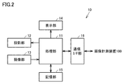
- FIG. 2 is a schematic diagram showing the configuration of the functional block of the measuring head shown in FIG. 1
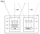
- FIG. 3 is a schematic diagram showing the concept of a specific structure of the measuring head shown in FIG. Next, the configuration of the measuring head 10 will be described with reference to FIGS. 2 and 3.
- the measuring head 10 includes a processing unit 11, a projection unit 12 and an imaging unit 13 described above, a display unit 14, a storage unit 15, and a communication interface (I / F) unit 16. I'm out.
- the projection unit 12 projects the projection pattern onto the subject as described above, and the imaging unit 13 images the subject on which the projection pattern is projected.
- the processing unit 11 controls the entire processing in the measuring head 10.
- the processing unit 11 typically includes a processor, a storage for storing an instruction code executed by the processor, and a memory for expanding the instruction code.
- the processor expands the instruction code on the memory and executes it to realize various processes. All or part of the processing unit 11 may be implemented using a dedicated hardware circuit (for example, ASIC (Application Specific Integrated Circuit) or FPGA (Field-Programmable Gate Array)).
- ASIC Application Specific Integrated Circuit
- FPGA Field-Programmable Gate Array
- the display unit 14 notifies the outside of various information acquired or calculated by the measurement head 10.
- the storage unit 15 stores an image captured by the image pickup unit 13, preset calibration parameters, and the like.
- the communication interface unit 16 is in charge of exchanging data between the measurement head 10 and the image measurement device 100.
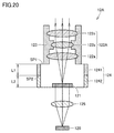
- the projection unit 12 includes a light source 120 and a photomask 121 which are pattern illumination forming elements as optical devices, a light projecting lens 122 as an optical lens, and a lens barrel and a support structure portion (not shown) which will be described later. And have. That is, the projection unit 12 is composed of an assembly for a three-dimensional measuring device, which is composed of the light source 120, the photomask 121, the projection lens 122, the lens barrel, and the support structure unit assembled to each other. The detailed structure will be described later.
- the light source 120 irradiates light having a predetermined wavelength toward the photomask 121.
- a predetermined pattern is formed on the photomask 121.
- the light that has passed through the photomask 121 is irradiated to the outside through the projection lens 122. As a result, the projection pattern is irradiated on the external space.
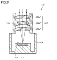
- the image pickup unit 13 has an image pickup element 131 as an optical device, a light receiving lens 132 as an optical lens, and a lens barrel and a support structure portion (not shown) described later. That is, the image pickup unit 13 is composed of an assembly for a three-dimensional measuring device, which is formed by assembling the image pickup element 131, the light receiving lens 132, the lens barrel, and the support structure portion with each other. Will be described later.
- the imaging unit 13 images a subject in a state where the projection pattern is projected. Specifically, the input image is obtained by receiving the light that has passed through the light receiving lens 132 by the image sensor 131.
- FIG. 4 is a schematic diagram showing a configuration of a functional block of the image measuring device shown in FIG. Next, the configuration of the functional block of the image measuring device 100 will be described with reference to FIG.
- the image measuring device 100 is typically realized by using a general-purpose computer.
- the image measuring device 100 includes a processor 102, a main memory 104, a storage 106, an input unit 108, a display unit 110, an optical drive 112, a lower interface unit 114, and an upper interface unit 116. These components are connected via the processor bus 118.
- the processor 102 is composed of a CPU (Central Processing Unit), a GPU (Graphics Processing Unit), etc., reads a program (OS 1060 and a three-dimensional measurement program 1062 as an example) stored in the storage 106, and expands the program to the main memory 104. By executing this, various processes as described later are realized.
- a CPU Central Processing Unit
- GPU Graphics Processing Unit
- the main memory 104 is composed of a volatile storage device such as a DRAM (Dynamic Random Access Memory) or a SRAM (Static Random Access Memory).
- the storage 106 is composed of, for example, a non-volatile storage device such as an HDD (Hard Disk Drive) or an SSD (Solid State Drive).
- the three-dimensional measurement program 1062 for providing the functions as the image measuring device 100 is stored.
- the input unit 108 is composed of a keyboard, a mouse, etc., and accepts user operations.
- the display unit 110 is composed of a display, various indicators, a printer, and the like, and outputs a processing result and the like from the processor 102.
- the lower interface unit 114 is in charge of exchanging data with the measurement head 10.
- the upper interface unit 116 is in charge of exchanging data with a higher device (for example, PLC (programmable computer)) (not shown).
- PLC programmable computer
- the image measuring device 100 has an optical drive 112, and is included in a recording medium 115 (for example, an optical recording medium such as a DVD (Digital Versatile Disc)) that temporarily stores a computer-readable program.
- a recording medium 115 for example, an optical recording medium such as a DVD (Digital Versatile Disc)
- the program stored in is read and installed in the storage 106 or the like.
- the three-dimensional measurement program 1062 or the like executed by the image measuring device 100 may be installed via a computer-readable recording medium 115, but is installed so as to be downloaded from a server device or the like on the network. May be good. Further, the function provided by the three-dimensional measurement program 1062 according to the present embodiment may be realized by using a part of the module provided by the OS.
- FIG. 4 shows a configuration example in which the functions required for the image measuring device 100 are provided by executing the program by the processor 102, and some or all of these provided functions are provided by dedicated hardware. It may be implemented using a hardware circuit (for example, ASIC or FPGA).
- three-dimensional measurement is realized by using a method called structured lighting.
- structured lighting method a predetermined projection pattern is projected onto the subject, and the position of each part of the subject (distance from the measurement head) is based on an image obtained by imaging the subject in a state where the projection pattern is projected. Is measured, thereby measuring the three-dimensional shape of the subject.
- a method of irradiating measurement light having a predetermined projection pattern (typically, a shading pattern) is adopted.
- the irradiation surface of the projection unit 12 is regarded as the “irradiation reference surface” of the projection pattern P.
- the optical parameters of the projection unit 12 and the imaging unit 13 and the matrix relating them are determined in advance. Has been done.
- the optical parameters of the projection unit 12 and the imaging unit 13 are both determined based on the same reference point, and if the height of the projection surface of the projection unit 12 is specified, the projection pattern emitted from the projection unit 12 is imaged. It is possible to calculate which pixel on the imaging surface of the unit 13 corresponds to.
- the size and position (expansion and contraction of the interval between adjacent elements) of the projection pattern emitted from the projection unit 12 changes according to the position and inclination of the subject with respect to the optical axis of the projection unit 12, and such information. Based on the above, the shape of the subject can be measured by the principle of triangulation.
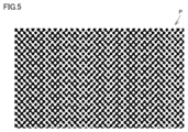
- FIG. 5 is a diagram showing an example of a projection pattern irradiated from the measurement head in the three-dimensional measuring device according to the present embodiment.
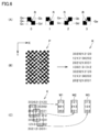
- FIG. 6 is a diagram for explaining the principle of three-dimensional measurement executed by the three-dimensional measuring device according to the present embodiment.
- the projection unit 12 of the measurement head 10 irradiates the subject with measurement light including the projection pattern P as shown in FIG.
- the imaging unit 13 of the measuring head 10 images the subject in a state where the projection pattern P is projected.
- the projection pattern P shown in FIG. 5 is a pattern in which spatial codes are arranged in a grid pattern (hereinafter, also referred to as “grid code”), and is unique so that no autocorrelation occurs for a pattern having a predetermined length in a predetermined direction. Code is assigned. More specifically, the projection pattern P is defined by a combination of a plurality of types of primitives (corresponding to a reference pattern).
- FIG. 6 (A) shows four types of primitives.
- Each primitive shows a code assigned to it (in the example shown in FIG. 6 (A), four numerical values 1 to 4).
- Each primitive consists of four large squares Qa-Qd and one small square Qe located in the center.
- Each of the squares Qa to Qd is arranged so that the primitive position R is a corner.
- the primitive position R is also the center position of the small square Qe.
- the intersection of large squares Qa to Qd (one corner of the grid) is defined as the primitive position R.
- the size and shape of the primitive position R are not limited.
- Each of the primitives is restored as one of the three-dimensional points.
- p0 1 when the primitive position R is “white”
- p0 0 when the primitive position R is “black”
- p1 when the large square Qb on the upper left of the primitive position R is “white”.
- p1 0.
- the type of primitive can be expressed numerically as 2p1 + p0.
- FIG. 6B is a numerical representation of the types of primitives included in the projection pattern P (see FIG. 5). That is, by specifying the type of each primitive included in the projection pattern P and expressing the type of each specified primitive numerically, a matrix K equivalent to the projection pattern P can be generated.
- the in-plane direction of the projection pattern P is defined as the X direction and the Y direction
- the optical axis direction (height) direction is defined as the Z direction.
- FIG. 6 (C) shows a submatrix of the matrix K shown in FIG. 6 (B).
- a submatrix of a predetermined size (word height Hword ⁇ word width Word) set in the matrix K is assumed.
- Such a submatrix is also referred to as a "word”. That is, each word is defined by a combination of a predetermined number of primitive types (3 ⁇ 3 in the example shown in FIG. 6C).
- the projection pattern P is generated by arranging the primitives so that each of all the words is unique.
- All words included in the matrix K are extracted from the input image acquired by capturing the image with the projection pattern P projected onto the subject.
- the process of extracting primitives and identifying or reconstructing words is also referred to as (word) "decoding".
- FIG. 6C shows the three extracted words (words W1, W2, W3).
- the position of the word specified from the projected image changes according to the surface shape of the subject.
- the measurement head 10 is based on the size of words defined by the primitives included in the image obtained by imaging the subject and the positional deviation between adjacent words. The distance from each part of the subject and the three-dimensional shape of the subject can be measured.
- adjacent words W1 to W3 share a part of primitives.
- the image measuring device 100 executes a primitive extraction process and a word position and size evaluation process specified by the extracted primitive on the image output from each measurement head 10. Outputs the measurement result of the three-dimensional shape of the subject.
- FIG. 6A shows an example of using four types of primitives, but the number of types of primitives is not limited to four. Further, any shape and color can be adopted without being limited to the shape and color of the primitive as shown in FIG. 6 (A).
- the problem to be solved by the present disclosure is, in summary, to prevent the measurement range from being extremely narrowed or the measurement range itself from disappearing in the defined temperature range, as described above.
- the measurement range means the range of the distance along the optical axis direction between the measurement head and the subject capable of measuring the three-dimensional shape of the subject, and the measurement range is extremely wide. If the measurement range itself is narrowed or the measurement range itself does not exist, the three-dimensional shape of the subject cannot be measured.
- This measurement range includes a measurement range on the projection unit side and a measurement range on the imaging unit side.
- the projection pattern projected on the subject becomes blurry, and the projection pattern in the input image becomes unclear.
- the image formed on the image pickup surface of the image pickup device becomes blurry, and the projection pattern in the input image becomes unclear. Therefore, in any case, the above-mentioned primitive cannot be extracted from the acquired input image, and as a result, it becomes impossible to measure the three-dimensional shape of the subject.
- the measurement head of the three-dimensional measuring device has an optical lens (projection lens) for forming a projection pattern on the subject and an image of the projection pattern projected on the subject.
- An optical lens (light receiving lens) for forming an image on the image pickup surface is provided.
- These optical lenses are generally composed of a composite lens in which a plurality of lenses are combined, but usually have a property (temperature characteristic) that the focal position changes according to the temperature. The temperature characteristics of this optical lens have a great influence on the presence or absence of the measurement range and the width of the measurement range described above.
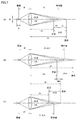
- FIG. 7 is a diagram showing a measurement range on the imaging unit side of the three-dimensional measuring device shown in FIG.
- FIG. 7 shows a state in which the light receiving lens 132 is at the temperature T
- FIG. 7 (B) shows a state in which the light receiving lens 132 has been heated to the temperature T + ⁇ T
- FIG. 7 (C) Indicates a state in which the light receiving lens 132 has been cooled to the temperature T ⁇ T.
- examples of the light receiving lens 132 to be used include those whose focal position changes in the direction away from the focal point as the temperature rises.
- the light receiving lens 132 forms an object surface and an image surface as a pair of conjugate surfaces having an optically conjugate relationship.
- the object distance A which is the distance from the principal point of the light receiving lens 132 to the object surface
- the image distance B which is the distance from the principal point of the light receiving lens 132 to the image plane, are described below using the focal length f of the light receiving lens 132. It is determined by the equation (1) of.
- the image of the subject is clearly imaged on the image pickup surface of the image pickup element 131.
- the light receiving lens 132 has a depth of focus ⁇ determined by its permissible scattering circle diameter ⁇ , and as long as the image sensor 131 is arranged within the range of the depth of focus ⁇ , the image of the subject is the image sensor 131. It will be clearly imaged on the image pickup surface of.
- the measurement range on the light receiving side is determined by the depth of field DOC (Depth of Field).
- the depth of field DOF is a range along the optical axis direction on the side where the subject is placed, in which an image is clearly formed on the image plane, and is a front side image located on the light receiving lens 132 side when viewed from the object surface. It is expressed as the sum of the field depth Lf and the rear side depth of field Lr located on the side opposite to the light receiving lens 132 side when viewed from the object surface.
- the end point on the light receiving lens 132 side of the depth of field DOF is referred to as a "near point”, and the end point on the side opposite to the light receiving lens 132 side of the depth of field DOF is referred to as a "far point”.
- the near point distance Sn which is the distance from the principal point of the light receiving lens 132 to the near point
- the far point distance Sf which is the distance from the principal point to the far point of the light receiving lens 132
- the subject is the light receiving lens.
- the distance from 132 within the range of the near point distance Sn or more represented by the above formula (2) and the far point distance Sf or less represented by the above formula (3), the subject is clearly input.
- the image can be acquired. That is, the range is the measurement range at the temperature T.
- the measurement range at the temperature T + ⁇ T shifts in the direction away from the light receiving lens 132 than the measurement range at the temperature T described above.
- the measurement range at the temperature T ⁇ T shifts toward the light receiving lens 132 more than the measurement range at the temperature T described above.
- the actual measurement range in the three-dimensional measuring device is the light receiving lens.
- the distance from 132 is in the range of the near point distance Sn or more at the temperature T + ⁇ T represented by the above formula (4) and the far point distance Sf or less at the temperature T ⁇ T represented by the above formula (7) (that is, in the figure).
- the range indicated by the symbol MR That is, in order to secure this practical measurement range MR, it is necessary to satisfy at least the conditions shown by (the right side of the above equation (4)) ⁇ (the right side of the above equation (7)).
- the apogee distance Sf at the temperature T ⁇ T represented by the above equation (7) is sufficiently larger than the perigee distance Sn at the temperature T + ⁇ T represented by the above equation (4). It needs to be big.
- the focal length f, the permissible scattering circle diameter ⁇ , and the brightness F are all determined by the optical characteristics of the light receiving lens 132 to be used, and although some fine adjustment is possible, they are various in realizing three-dimensional measurement. This is not something that can be set freely due to the restrictions of. Therefore, when the present inventor made various trial calculations assuming actual specifications, the above-mentioned practical measurement range MR was sufficiently satisfied while satisfying the above optical characteristics required for an optical lens in order to realize three-dimensional measurement. It was confirmed that it was extremely difficult to secure a wide range of MRs, and it was found that there was a problem that the actual measurement range MR was extremely narrowed or that it did not exist in the first place.
- the temperature characteristic of the light receiving lens 132 described above affects the measurement range on the image pickup unit 13 side of the three-dimensional measurement device 1.
- the temperature characteristics of the projection lens 122 also affect the measurement range on the projection unit 12 side of the three-dimensional measuring device 1.
- the present inventor adopts any one of the first configuration example or the fifth configuration example described later in the three-dimensional measuring device 1 according to the present embodiment to solve the problem. We are trying to solve it.
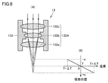
- the light receiving lens 132A is composed of a composite lens in which a plurality of lenses 132a to 132c are combined as described above, and the plurality of lenses 132a to 132c are light of each other. It is provided inside the lens barrel 133 so as to overlap the axes so as to be aligned in the axial direction of the lens barrel 133. Each of these plurality of lenses 132a to 132c has its peripheral edge supported by a lens barrel 133.
- the focal position (here, the image plane position) of the light receiving lens 132A at the temperature T is referred to along the optical axis direction.
- the focal position moves to the position + a which is a predetermined distance away from the light receiving lens 132A, and the light receiving lens 132A cools down to the temperature T ⁇ T.
- the focal position moves to a position-a closer to the light receiving lens 132A by a predetermined distance.
- the temperature characteristic of the light receiving lens 132A changes in the direction in which the focal position moves away from the light receiving lens 132A as the temperature rises.
- optical lenses having this type of temperature characteristic are collectively referred to. (That is, regardless of whether it is a light receiving lens or a floodlight lens), it is referred to as an "optical lens having a first temperature characteristic".
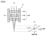
- the light receiving lens 132B is composed of a composite lens in which a plurality of lenses 132a'to 132c' are combined as described above, and the plurality of lenses 132a' to 132c' , They are provided so as to be aligned in the axial direction of the lens barrel 133 inside the lens barrel 133 so that their optical axes overlap each other.
- Each of these plurality of lenses 132a'to 132c' has its peripheral edge supported by a lens barrel 133.
- the focal position (here, the image plane position) of the light receiving lens 132B at the temperature T is along the optical axis direction.
- the focal position moves to the position ⁇ a which is a predetermined distance closer to the light receiving lens 132A, and the light receiving lens 132B moves to the temperature T ⁇ T.
- the focal position moves to a position + a that is a predetermined distance away from the light receiving lens 132B.
- the temperature characteristic of the light receiving lens 132B changes in the direction in which the focal position approaches the light receiving lens 132B as the temperature rises.
- optical lenses having this type of temperature characteristic are collectively referred to. (That is, regardless of whether it is a light receiving lens or a floodlight lens), it is referred to as an "optical lens having a second temperature characteristic".
- the optical lens is configured as a composite lens of three lenses, but naturally the number of lenses to be combined is not limited.
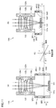
- FIG. 10 is a schematic cross-sectional view showing a first configuration example of the imaging unit
- FIG. 11 is a diagram showing the behavior of the imaging unit shown in FIG. 10 with a temperature change.
- the imaging unit 13A according to the first configuration example will be described with reference to FIGS. 10 and 11.
- the image pickup unit 13A includes an image pickup element 131 as an optical device, a light receiving lens 132A as an optical lens, a lens barrel 133, and a support structure portion 134, which are assembled with each other. It is composed of an assembly for a three-dimensional measuring device that is configured by being attached.
- the light receiving lens 132A according to this configuration example is an optical lens having the above-mentioned first temperature characteristic.
- the image sensor 131 is composed of, for example, a CMOS (Complementary Metal Oxide Semiconductor) image sensor, a CCD (Charged-Coupled Devices) image sensor, or the like, and is supported by the support structure unit 134.
- the support structure portion 134 has a box shape capable of accommodating the image pickup element 131 inside, and the image pickup element 131 is mounted on the bottom portion thereof.
- the image pickup device 131 has an image pickup surface 131a on its surface, and the image pickup surface 131a faces the light receiving lens 132A side.
- the light receiving lens 132A is supported by a tubular lens barrel 133, and is arranged so as to face the image pickup surface 131a of the image pickup element 131.
- the specific configuration of the light receiving lens 132A and the lens barrel 133 is the same as the configuration shown in FIG. 8 described above.
- the lower end of the lens barrel 133 is fixed at a predetermined position on the upper end side of the support structure portion 134.
- the support structure portion 134 supports the image pickup element 131 and the lens barrel 133 is fixed, thereby determining the relative positional relationship between the image pickup element 131 and the light receiving lens 132A.
- the support structure portion 134 has a first member 1341 and a second member 1342 having different linear expansion coefficients. By combining the first member 1341 and the second member 1342 having different linear expansion coefficients, the support structure portion 134 increases the distance between the elements, which is the distance between the image sensor 131 and the light receiving lens 132A in the optical axis direction, according to the temperature. It consists of a composite structure adjusted to fluctuate. In this configuration example, the coefficient of linear expansion of the first member 1341 is larger than the coefficient of linear expansion of the second member 1342.
- the support structure portion 134 is the first member 1341 arranged in a portion of the composite structure that is relatively closer to the portion to which the lens barrel 133 is fixed than the portion that supports the image sensor 131.
- a second member 1342 arranged in a portion of the composite structure that is relatively closer to the portion that supports the image sensor 131 than the portion to which the lens barrel 133 is fixed.
- the member 1341 and the second member 1342 are arranged so as to be arranged along a direction parallel to the optical axis direction.
- the image sensor 131 has a focal position (here) of the light receiving lens 132A at a predetermined temperature T by adjusting the dimensions of each portion of the support structure portion 134 made of the composite structure along the optical axis direction. It is arranged so as to match the image plane position). As a result, at the predetermined temperature T, the subject is arranged within the range of the depth of field of the light receiving lens 132A, so that the image of the subject is clearly imaged on the image pickup surface 131a of the image pickup element 131. become.
- the lens barrel 133 and the first member 1341 may be fixed so as to be in contact with each other, or other members may be arranged between them so as to intervene between them.
- the first member 1341 and the second member 1342 may be fixed so as to be in contact with each other, or other members may be arranged between them so as to intervene between them.
- the second member 1342 and the image sensor 131 may be fixed so as to be in contact with each other, or another member may be arranged between them so as to intervene between them.
- it is preferable to consider their shape, linear expansion coefficient, etc. so as not to substantially affect the fluctuation of the distance between elements due to the temperature described above.
- the lens barrel 133 and the first member 1341 are fixed so as to be in contact with each other, and the first member 1341 and the second member 1342 are fixed so as to be in contact with each other.
- the image sensor 131 is fixed so as to be in contact with each other.
- the illustration of the connection portion between the lens barrel 133 and the first member 1341 and the connection portion between the second member 1342 and the image sensor 131 is simplified.
- connection position of the lens barrel 133 and the first member 1341 is set to the first reference position SP1
- connection position of the first member 1341 and the second member 1342 is set to the second reference position SP2
- optical axis direction of the first member 1341 The length along the line is L1
- the linear expansion coefficient of the first member 1341 is K1
- the length of the second member 1342 along the optical axis is L2
- the linear expansion coefficient of the second member 1342 is K2.
- the temperature characteristics of the light receiving lens 132A show.
- the focal position moves in the direction away from the light receiving lens 132A. That is, the focal position of the light receiving lens 132A moves from the reference position shown in FIG. 10 to the position + a.
- the support structure portion 134 provided close to the light receiving lens 132A is also similarly heated by the temperature ⁇ T from the predetermined temperature T, and the first member 1341 and the second member 1342 are both extended.
- the first member 1341 is elongated from the first reference position SP1 in the direction away from the light receiving lens 132A along the optical axis direction (the direction and magnitude of this elongation are shown in the drawing. Is schematically shown by the arrow AR11).
- the second reference position SP2 moves in the direction away from the light receiving lens 132A by the amount of extension of the first member 1341.
- the second member 1342 also undergoes elongation from the second reference position SP2 in the direction away from the light receiving lens 132A along the optical axis direction (the direction and magnitude of this elongation are shown in the drawing. It is schematically shown by the arrow AR21).
- the image sensor 131 moves in the direction away from the light receiving lens 132A by the sum of the elongation amount of the first member 1341 and the elongation amount of the second member 1342.
- the distance between the elements which is the distance between the image sensor 131 and the light receiving lens 132A in the optical axis direction, increases by the distance Lh as the temperature rises from the temperature T to the temperature ⁇ T.
- the distance Lh is expressed by the following equation (8).
- the temperature of the support structure portion 134 provided close to the light receiving lens 132A also drops by the temperature ⁇ T from the predetermined temperature T, and both the first member 1341 and the second member 1342 contract.
- the first member 1341 shrinks in the direction approaching the light receiving lens 132A along the optical axis direction with the first reference position SP1 as a base point (the direction and magnitude of this shrinkage are shown in the drawing. Is schematically shown by the arrow AR12).
- the second reference position SP2 moves in the direction closer to the light receiving lens 132A by the amount of contraction of the first member 1341.
- the second member 1342 also shrinks in the direction approaching the light receiving lens 132A along the optical axis direction with the second reference position SP2 as the base point (the direction and magnitude of this shrinkage are shown in the drawing. It is schematically shown by the arrow AR22). Along with this, the image sensor 131 moves in the direction closer to the light receiving lens 132A by the sum of the amount of shrinkage of the first member 1341 and the amount of shrinkage of the second member 1342.
- the distance between the elements which is the distance between the image sensor 131 and the light receiving lens 132A in the optical axis direction, decreases by the distance Ll as the temperature drops from the temperature T by the temperature ⁇ T.
- the distance Ll is expressed by the following equation (9).
- the distance Lh which is the amount of increase in the distance between the elements when the temperature rises
- the distance Ll which is the amount of decrease in the distance between the elements when the temperature is lowered
- the distance Ll can be adjusted to the amount of movement when the focal position of the light receiving lens 132A moves to the position ⁇ a when the temperature is lowered.
- the support structure portion is composed of a single member, the fluctuation of the distance between the elements due to the temperature change is determined almost uniquely. It becomes virtually impossible to adjust to the change in the focal position of the light receiving lens in response to the temperature change.
- the support structure portion by forming the support structure portion with a combination of at least two or more members having different linear expansion coefficients, it becomes possible to arbitrarily determine the fluctuation of the distance between the elements due to the temperature change. This makes it possible to easily adjust the fluctuation of the distance between the elements due to the temperature change to the change of the focal position of the light receiving lens according to the temperature change.
- the imaging unit 13A it is possible to make the fluctuation of the inter-element distance follow the change of the focal position, and at least a part of the deviation amount of the focal position is the inter-element distance. It can be offset by fluctuations. Therefore, by using the imaging unit 13A having the above configuration, it is possible to contribute to securing a wide measurement range in a predetermined temperature range when the three-dimensional measuring device 1 equipped with the imaging unit 13A is provided.
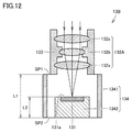
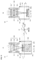
- FIG. 12 is a schematic cross-sectional view showing a second configuration example of the imaging unit
- FIG. 13 is a diagram showing the behavior of the imaging unit shown in FIG. 12 with a temperature change.
- the imaging unit 13B according to the second configuration example will be described with reference to FIGS. 12 and 13.
- the image pickup unit 13B is composed of an assembly for a three-dimensional measuring device including an image pickup element 131, a light receiving lens 132A, a lens barrel 133, and a support structure portion 134.
- the light receiving lens 132A according to this configuration example is an optical lens having the above-mentioned first temperature characteristic.
- the support structure portion 134 has a first member 1341 and a second member 1342 having different linear expansion coefficients, and the lower end of the lens barrel 133 is fixed at a predetermined position on the upper end side of the support structure portion 134. There is.
- the support structure portion 134 is composed of a composite structure in which the distance between the elements, which is the distance between the image sensor 131 and the light receiving lens 132A in the optical axis direction, is adjusted so as to fluctuate according to the temperature.
- the coefficient of linear expansion of the first member 1341 is larger than the coefficient of linear expansion of the second member 1342.
- the first member 1341 arranged in a portion of the composite structure that is relatively closer to the portion to which the lens barrel 133 is fixed than the portion that supports the image sensor 131 is the lens barrel 133 of the composite structure. Is located so as to surround the second member 1342 arranged in a portion relatively closer to the portion supporting the image sensor 131 than the portion to which the image sensor 131 is fixed. That is, the second member 1342 is housed inside the first member 1341, so that the first member 1341 and the second member 1342 partially overlap each other in the direction orthogonal to the optical axis direction. Have been placed.
- the image sensor 131 has a focal position (here) of the light receiving lens 132A at a predetermined temperature T by adjusting the dimensions of each portion of the support structure portion 134 made of the composite structure along the optical axis direction. It is arranged so as to match the image plane position).
- the lens barrel 133 and the first member 1341 are fixed so as to be in contact with each other, and the first member 1341 and the second member 1342 are fixed so as to be in contact with each other.
- the image sensor 131 is fixed so as to be in contact with each other.
- the connection portion between the lens barrel 133 and the first member 1341, the connection portion between the first member 1341 and the second member, and the second member 1342 and the image sensor 131 are shown. The illustration of the connection part with is simplified.
- FIG. 13 (A) when the temperature of the light receiving lens 132A rises by the temperature ⁇ T from the predetermined temperature T described above, the temperature characteristics of the light receiving lens 132A (see FIG. 13 (C)) show.
- the focal position moves in the direction away from the light receiving lens 132A. That is, the focal position of the light receiving lens 132A moves from the reference position shown in FIG. 12 to the position + a.
- the support structure portion 134 provided close to the light receiving lens 132A is also similarly heated by the temperature ⁇ T from the predetermined temperature T, and the first member 1341 and the second member 1342 are both extended.
- the first member 1341 is elongated from the first reference position SP1 in the direction away from the light receiving lens 132A along the optical axis direction (the direction and magnitude of this elongation are shown in the drawing. Is schematically shown by the arrow AR11).
- the second reference position SP2 moves in the direction away from the light receiving lens 132A by the amount of extension of the first member 1341.
- the second member 1342 is stretched from the second reference position SP2 in the direction approaching the light receiving lens 132A along the optical axis direction (the direction and magnitude of this stretching are shown in the drawing. It is schematically shown by the arrow AR21).
- the image sensor 131 moves in the direction away from the light receiving lens 132A by the difference between the amount of extension of the first member 1341 and the amount of extension of the second member 1342.
- the distance between the elements which is the distance between the image sensor 131 and the light receiving lens 132A in the optical axis direction, increases by the distance Lh as the temperature rises from the temperature T to the temperature ⁇ T.
- the distance Lh is expressed by the following equation (10).
- the focal point is determined by the temperature characteristics of the light receiving lens 132A (see FIG. 13 (C)).
- the position moves in the direction closer to the light receiving lens 132A. That is, the focal position of the light receiving lens 132A moves from the reference position shown in FIG. 10 to the position ⁇ a.
- the temperature of the support structure portion 134 provided close to the light receiving lens 132A also drops by the temperature ⁇ T from the predetermined temperature T, and both the first member 1341 and the second member 1342 contract.
- the first member 1341 shrinks in the direction approaching the light receiving lens 132A along the optical axis direction with the first reference position SP1 as a base point (the direction and magnitude of this shrinkage are shown in the drawing. Is schematically shown by the arrow AR12).
- the second reference position SP2 moves in the direction closer to the light receiving lens 132A by the amount of contraction of the first member 1341.
- the second member 1342 shrinks in the direction away from the light receiving lens 132A along the optical axis direction with the second reference position SP2 as the base point (the direction and magnitude of this shrinkage are shown in the drawing. It is schematically shown by the arrow AR22).
- the image sensor 131 moves in the direction closer to the light receiving lens 132A by the difference between the amount of contraction of the first member 1341 and the amount of contraction of the second member 1342.
- the distance between the elements which is the distance between the image sensor 131 and the light receiving lens 132A in the optical axis direction, decreases by the distance Ll as the temperature drops from the temperature T by the temperature ⁇ T.
- the distance Ll is expressed by the following equation (11).
- the distance Lh which is the amount of increase in the distance between the elements when the temperature rises
- the distance Ll which is the amount of decrease in the distance between the elements when the temperature is lowered
- the distance Ll can be adjusted to the amount of movement when the focal position of the light receiving lens 132A moves to the position ⁇ a when the temperature is lowered.
- the imaging unit 13B according to the second configuration example it is possible to make the fluctuation of the inter-element distance follow the change of the focal position, and at least a part of the deviation amount of the focal position is the inter-element distance. Can be offset by fluctuations in. Therefore, the same effect as in the case of using the imaging unit 13A according to the first configuration example described above can be obtained.
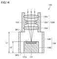
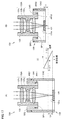
- FIG. 14 is a schematic cross-sectional view showing a third configuration example of the imaging unit
- FIG. 15 is a diagram showing the behavior of the imaging unit shown in FIG. 14 with a temperature change.
- the imaging unit 13C according to the third configuration example will be described with reference to FIGS. 14 and 15.
- the image pickup unit 13C is composed of an assembly for a three-dimensional measuring device including an image pickup element 131, a light receiving lens 132B, a lens barrel 133, and a support structure portion 134.
- the light receiving lens 132B according to this configuration example is an optical lens having the above-mentioned second temperature characteristic.
- the support structure portion 134 has a first member 1341 and a second member 1342 having different linear expansion coefficients, and the lower end of the lens barrel 133 is fixed at a predetermined position on the upper end side of the support structure portion 134. There is.
- the support structure portion 134 is composed of a composite structure in which the distance between the elements, which is the distance between the image sensor 131 and the light receiving lens 132B in the optical axis direction, is adjusted to vary depending on the temperature.
- the coefficient of linear expansion of the first member 1341 is smaller than the coefficient of linear expansion of the second member 1342.
- the first member 1341 arranged in a portion of the composite structure that is relatively closer to the portion to which the lens barrel 133 is fixed than the portion that supports the image sensor 131 is the lens barrel 133 of the composite structure. Is located so as to surround the second member 1342 arranged in a portion relatively closer to the portion supporting the image sensor 131 than the portion to which the image sensor 131 is fixed. That is, the second member 1342 is housed inside the first member 1341, so that the first member 1341 and the second member 1342 partially overlap each other in the direction orthogonal to the optical axis direction. Have been placed.
- the image pickup surface 131a has the focal position of the light receiving lens 132B at a predetermined temperature T (here). It is arranged so as to match the image plane position).
- the lens barrel 133 and the first member 1341 are fixed so as to be in contact with each other, and the first member 1341 and the second member 1342 are fixed so as to be in contact with each other.
- the image sensor 131 is fixed so as to be in contact with each other.
- the connection portion between the lens barrel 133 and the first member 1341, the connection portion between the first member 1341 and the second member, and the second member 1342 and the image sensor 131 are shown. The illustration of the connection part with is simplified.
- the temperature of the light receiving lens 132B when the temperature of the light receiving lens 132B is raised by the temperature ⁇ T from the predetermined temperature T described above, the temperature characteristics of the light receiving lens 132B (see FIG. 15C) The focal position moves in the direction closer to the light receiving lens 132B. That is, the focal position of the light receiving lens 132B moves from the reference position shown in FIG. 14 to the position ⁇ a.
- the support structure portion 134 provided in the vicinity of the light receiving lens 132B is also similarly heated by the temperature ⁇ T from the predetermined temperature T, and both the first member 1341 and the second member 1342 are extended.
- the first member 1341 is elongated from the first reference position SP1 in the direction away from the light receiving lens 132B along the optical axis direction (the direction and magnitude of this elongation are shown in the drawing. Is schematically shown by the arrow AR11).
- the second reference position SP2 moves in the direction away from the light receiving lens 132B by the amount of extension of the first member 1341.
- the second member 1342 is stretched from the second reference position SP2 in the direction closer to the light receiving lens 132B along the optical axis direction (the direction and magnitude of this stretching are shown in the drawing. It is schematically shown by the arrow AR21).
- the image sensor 131 moves in the direction closer to the light receiving lens 132A by the difference between the amount of elongation of the first member 1341 and the amount of extension of the second member 1342.
- the distance between the elements which is the distance between the image sensor 131 and the light receiving lens 132B in the optical axis direction, decreases by the distance Lh as the temperature rises from the temperature T to the temperature ⁇ T.
- the distance Lh is expressed by the following equation (12).
- the focal point is determined by the temperature characteristics of the light receiving lens 132B (see FIG. 15 (C)).
- the position moves in the direction away from the light receiving lens 132B. That is, the focal position of the light receiving lens 132B moves from the reference position shown in FIG. 14 to the position + a.
- the temperature of the support structure portion 134 provided close to the light receiving lens 132B also drops by the temperature ⁇ T from the predetermined temperature T, and both the first member 1341 and the second member 1342 contract.
- the first member 1341 shrinks in the direction approaching the light receiving lens 132B along the optical axis direction with the first reference position SP1 as a base point (the direction and magnitude of this shrinkage are shown in the drawing. Is schematically shown by the arrow AR12).
- the second reference position SP2 moves in the direction closer to the light receiving lens 132B by the amount of contraction of the first member 1341.
- the second member 1342 shrinks in the direction away from the light receiving lens 132B along the optical axis direction with the second reference position SP2 as the base point (the direction and magnitude of this shrinkage are shown in the drawing. It is schematically shown by the arrow AR22).
- the image sensor 131 moves in the direction away from the light receiving lens 132A by the difference between the amount of contraction of the first member 1341 and the amount of contraction of the second member 1342.
- the distance between the elements which is the distance between the image sensor 131 and the light receiving lens 132B in the optical axis direction, increases by the distance Ll as the temperature drops from the temperature T by the temperature ⁇ T.
- the distance Ll is expressed by the following equation (13).
- the distance Lh which is the amount of decrease in the distance between the elements when the temperature rises
- the distance Ll which is the amount of increase in the distance between the elements when the temperature is lowered
- the distance Ll which is the amount of increase in the distance between the elements when the temperature is lowered, can be adjusted to the amount of movement when the focal position of the light receiving lens 132B moves to the position + a when the temperature is lowered.
- the imaging unit 13C according to the third configuration example it is possible to make the fluctuation of the inter-element distance follow the change of the focal position, and at least a part of the deviation amount of the focal position is the inter-element distance. Can be offset by fluctuations in. Therefore, the same effect as in the case of using the imaging unit 13A according to the first configuration example described above can be obtained.
- FIG. 16 is a schematic cross-sectional view showing a fourth configuration example of the imaging unit
- FIG. 17 is a diagram showing the behavior of the imaging unit shown in FIG. 16 with a temperature change.
- the imaging unit 13D according to the fourth configuration example will be described with reference to FIGS. 16 and 17.
- the image pickup unit 13D is composed of an assembly for a three-dimensional measuring device including an image pickup element 131, a light receiving lens 132A, a lens barrel 133, and a support structure portion 134.
- the light receiving lens 132A according to this configuration example is an optical lens having the above-mentioned first temperature characteristic.
- the support structure portion 134 has a first member 1341 and a second member 1342 having different linear expansion coefficients, and the lower end of the lens barrel 133 is fixed at a predetermined position on the upper end side of the support structure portion 134. There is.
- the support structure portion 134 is composed of a composite structure in which the distance between the elements, which is the distance between the image sensor 131 and the light receiving lens 132A in the optical axis direction, is adjusted so as to fluctuate according to the temperature.
- the coefficient of linear expansion of the first member 1341 is smaller than the coefficient of linear expansion of the second member 1342.
- the second member 1342 arranged in a portion of the composite structure that is relatively closer to the portion that supports the image sensor 131 than the portion to which the lens barrel 133 is fixed is the image sensor 131 of the composite structure. It is located so as to surround the first member 1341 arranged in a portion relatively closer to the portion to which the lens barrel 133 is fixed than the portion supporting the lens barrel 133. That is, the first member 1341 is housed inside the second member 1342, so that the first member 1341 and the second member 1342 partially overlap in the direction orthogonal to the optical axis direction. Have been placed.
- the lower end side portion of the lens barrel 133 is located inside the support structure portion 134.
- the image sensor 131 has a focal position (here) of the light receiving lens 132A at a predetermined temperature T by adjusting the dimensions of each portion of the support structure portion 134 made of the composite structure along the optical axis direction. It is arranged so as to match the image plane position).
- the lens barrel 133 and the first member 1341 are fixed so as to be in contact with each other, and the first member 1341 and the second member 1342 are fixed so as to be in contact with each other.
- the image sensor 131 is fixed so as to be in contact with each other.
- the connection portion between the lens barrel 133 and the first member 1341, the connection portion between the first member 1341 and the second member, and the second member 1342 and the image sensor 131 are shown. The illustration of the connection part with is simplified.
- the temperature characteristics of the light receiving lens 132A show.
- the focal position moves in the direction away from the light receiving lens 132A. That is, the focal position of the light receiving lens 132A moves from the reference position shown in FIG. 16 to the position + a.
- the support structure portion 134 provided close to the light receiving lens 132A is also similarly heated by the temperature ⁇ T from the predetermined temperature T, and the first member 1341 and the second member 1342 are both extended.
- the first member 1341 is stretched from the first reference position SP1 in the direction approaching the light receiving lens 132A along the optical axis direction (the direction and magnitude of this stretching are shown in the drawing. Is schematically shown by the arrow AR11).
- the second reference position SP2 moves in the direction closer to the light receiving lens 132A by the amount of extension of the first member 1341.
- the second member 1342 is elongated from the second reference position SP2 in the direction away from the light receiving lens 132A along the optical axis direction (the direction and magnitude of this elongation are shown in the drawing. It is schematically shown by the arrow AR21).
- the image sensor 131 moves in the direction away from the light receiving lens 132A by the difference between the amount of extension of the first member 1341 and the amount of extension of the second member 1342.
- the distance between the elements which is the distance between the image sensor 131 and the light receiving lens 132A in the optical axis direction, increases by the distance Lh as the temperature rises from the temperature T to the temperature ⁇ T.
- the distance Lh is expressed by the following equation (14).
- the focal point is determined by the temperature characteristics of the light receiving lens 132A (see FIG. 17 (C)).
- the position moves in the direction closer to the light receiving lens 132A. That is, the focal position of the light receiving lens 132A moves from the reference position shown in FIG. 16 to the position ⁇ a.
- the temperature of the support structure portion 134 provided close to the light receiving lens 132A also drops by the temperature ⁇ T from the predetermined temperature T, and both the first member 1341 and the second member 1342 contract.
- the first member 1341 shrinks in the direction away from the light receiving lens 132A along the optical axis direction with the first reference position SP1 as a base point (the direction and magnitude of this shrinkage are shown in the drawing. Is schematically shown by the arrow AR12).
- the second reference position SP2 moves in the direction away from the light receiving lens 132A by the amount of contraction of the first member 1341.
- the second member 1342 shrinks in the direction approaching the light receiving lens 132A along the optical axis direction with the second reference position SP2 as the base point (the direction and magnitude of this shrinkage are shown in the drawing. It is schematically shown by the arrow AR22).
- the image sensor 131 moves in the direction closer to the light receiving lens 132A by the difference between the amount of contraction of the first member 1341 and the amount of contraction of the second member 1342.
- the distance between the elements which is the distance between the image sensor 131 and the light receiving lens 132A in the optical axis direction, decreases by the distance Ll as the temperature drops from the temperature T by the temperature ⁇ T.
- the distance Ll is expressed by the following equation (15).
- the distance Lh which is the amount of increase in the distance between the elements when the temperature rises
- the distance Ll which is the amount of decrease in the distance between the elements when the temperature is lowered
- the distance Ll can be adjusted to the amount of movement when the focal position of the light receiving lens 132A moves to the position ⁇ a when the temperature is lowered.
- the imaging unit 13D according to the fourth configuration example it is possible to make the fluctuation of the inter-element distance follow the change of the focal position, and at least a part of the deviation amount of the focal position is the inter-element distance. Can be offset by fluctuations in. Therefore, the same effect as in the case of using the imaging unit 13A according to the first configuration example described above can be obtained.
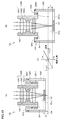
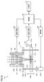
- FIG. 18 is a schematic cross-sectional view showing a fifth configuration example of the imaging unit
- FIG. 19 is a diagram showing the behavior of the imaging unit shown in FIG. 18 with a temperature change.
- the imaging unit 13E according to the fifth configuration example will be described with reference to FIGS. 18 and 19.
- the image pickup unit 13E is composed of an assembly for a three-dimensional measuring device including an image pickup element 131, a light receiving lens 132B, a lens barrel 133, and a support structure portion 134.
- the light receiving lens 132B according to this configuration example is an optical lens having the above-mentioned second temperature characteristic.
- the support structure portion 134 has a first member 1341 and a second member 1342 having different linear expansion coefficients, and the lower end of the lens barrel 133 is fixed at a predetermined position on the upper end side of the support structure portion 134. There is.
- the support structure portion 134 is composed of a composite structure in which the distance between the elements, which is the distance between the image sensor 131 and the light receiving lens 132B in the optical axis direction, is adjusted to vary depending on the temperature.
- the coefficient of linear expansion of the first member 1341 is larger than the coefficient of linear expansion of the second member 1342.
- the second member 1342 arranged in a portion of the composite structure that is relatively closer to the portion that supports the image sensor 131 than the portion to which the lens barrel 133 is fixed is the image sensor 131 of the composite structure. It is located so as to surround the first member 1341 arranged in a portion relatively closer to the portion to which the lens barrel 133 is fixed than the portion supporting the lens barrel 133. That is, the first member 1341 is housed inside the second member 1342, so that the first member 1341 and the second member 1342 partially overlap in the direction orthogonal to the optical axis direction. Have been placed.
- the lower end side portion of the lens barrel 133 is located inside the support structure portion 134.
- the image pickup surface 131a has the focal position of the light receiving lens 132B at a predetermined temperature T (here). It is arranged so as to match the image plane position).
- the lens barrel 133 and the first member 1341 are fixed so as to be in contact with each other, and the first member 1341 and the second member 1342 are fixed so as to be in contact with each other.
- the image sensor 131 is fixed so as to be in contact with each other.
- the connection portion between the lens barrel 133 and the first member 1341, the connection portion between the first member 1341 and the second member, and the second member 1342 and the image sensor 131 are shown. The illustration of the connection part with is simplified.
- the temperature of the light receiving lens 132B when the temperature of the light receiving lens 132B is raised by the temperature ⁇ T from the predetermined temperature T described above, the temperature characteristics of the light receiving lens 132B (see FIG. 19C) The focal position moves in the direction closer to the light receiving lens 132B. That is, the focal position of the light receiving lens 132B moves from the reference position shown in FIG. 18 to the position ⁇ a.
- the support structure portion 134 provided in the vicinity of the light receiving lens 132B is also similarly heated by the temperature ⁇ T from the predetermined temperature T, and both the first member 1341 and the second member 1342 are extended.
- the first member 1341 is stretched from the first reference position SP1 in the direction approaching the light receiving lens 132B along the optical axis direction (the direction and magnitude of this stretching are shown in the drawing. Is schematically shown by the arrow AR11).
- the second reference position SP2 moves in the direction closer to the light receiving lens 132B by the amount of extension of the first member 1341.
- the second member 1342 is elongated from the second reference position SP2 in the direction away from the light receiving lens 132B along the optical axis direction (the direction and magnitude of this elongation are shown in the drawing. It is schematically shown by the arrow AR21).
- the image sensor 131 moves in the direction closer to the light receiving lens 132B by the difference between the elongation amount of the first member 1341 and the elongation amount of the second member 1342.
- the distance between the elements which is the distance between the image sensor 131 and the light receiving lens 132B in the optical axis direction, decreases by the distance Lh as the temperature rises from the temperature T to the temperature ⁇ T.
- the distance Lh is expressed by the following equation (16).
- the focal point is determined by the temperature characteristics of the light receiving lens 132B (see FIG. 19 (C)).
- the position moves in the direction away from the light receiving lens 132B. That is, the focal position of the light receiving lens 132B moves from the reference position shown in FIG. 18 to the position + a.
- the temperature of the support structure portion 134 provided close to the light receiving lens 132B also drops by the temperature ⁇ T from the predetermined temperature T, and both the first member 1341 and the second member 1342 contract.
- the first member 1341 shrinks in the direction away from the light receiving lens 132A along the optical axis direction with the first reference position SP1 as a base point (the direction and magnitude of this shrinkage are shown in the drawing. Is schematically shown by the arrow AR12).
- the second reference position SP2 moves in the direction away from the light receiving lens 132B by the amount of contraction of the first member 1341.
- the second member 1342 shrinks in the direction approaching the light receiving lens 132A along the optical axis direction with the second reference position SP2 as the base point (the direction and magnitude of this shrinkage are shown in the drawing. It is schematically shown by the arrow AR22).
- the image sensor 131 moves in the direction away from the light receiving lens 132A by the difference between the amount of contraction of the first member 1341 and the amount of contraction of the second member 1342.
- the distance between the elements which is the distance between the image sensor 131 and the light receiving lens 132B in the optical axis direction, increases by the distance Ll as the temperature drops from the temperature T by the temperature ⁇ T.
- the distance Ll is expressed by the following equation (17).
- the distance Lh which is the amount of decrease in the distance between the elements when the temperature rises
- the distance Ll which is the amount of increase in the distance between the elements when the temperature is lowered
- the distance Ll which is the amount of increase in the distance between the elements when the temperature is lowered, can be adjusted to the amount of movement when the focal position of the light receiving lens 132B moves to the position + a when the temperature is lowered.
- the imaging unit 13E according to the fifth configuration example it is possible to make the fluctuation of the inter-element distance follow the change of the focal position, and at least a part of the deviation amount of the focal position is the inter-element distance. Can be offset by fluctuations in. Therefore, the same effect as in the case of using the imaging unit 13A according to the first configuration example described above can be obtained.
- FIG. 20 is a schematic cross-sectional view showing a configuration example of the projection unit.
- the projection unit 12A according to this configuration example will be described with reference to FIG. 20.
- the projection unit 12A includes a light source 120 and a photomask 121 as an optical device, a floodlight lens 122A as an optical lens, a lens barrel 123, a support structure unit 124, and a collimator lens 125. It is composed of an assembly for a three-dimensional measuring device, which is configured by assembling them together.
- the floodlight lens 122A according to this configuration example is an optical lens having the above-mentioned first temperature characteristic.
- the light source 120 and the photomask 121 are pattern illumination forming elements that form pattern illumination, and as the light source 120 among them, for example, an LED (Light Emitting Diode), an LD (Laser diode), a mercury lamp, or the like can be used.
- the pattern illumination forming element for example, a combination of a light source and a liquid crystal device, a combination of a light source and a micromirror array, an organic EL (electro-luminescence), or the like can be used.
- the peripheral edge of the photomask 121 is supported by the support structure portion 124.
- the photomask 121 is arranged so as to face the floodlight lens 122A.
- the collimator lens 125 and the light source 120 are arranged at positions opposite to the light projecting lens 122A side when viewed from the photomask 121.
- the collimator lens 125 converts the light emitted from the light source 120 into parallel light.
- the floodlight lens 122A is supported by a tubular lens barrel 123.
- the specific configuration of the light projecting lens 122A and the lens barrel 123 is the same as the configuration of the light receiving lens 132A and the lens barrel 133 shown in FIG. 8 described above.
- the lower end of the lens barrel 123 is fixed at a predetermined position on the upper end side of the support structure portion 124.
- the support structure portion 124 supports the photomask 121 and the lens barrel 123 is fixed, thereby determining the relative positional relationship between the photomask 121 and the projection lens 122A.
- the support structure portion 124 has a first member 1241 and a second member 1242 having different linear expansion coefficients. By combining the first member 1241 and the second member 1242 having different linear expansion coefficients, the support structure portion 124 increases the inter-element distance, which is the distance between the photomask 121 and the light projecting lens 122A in the optical axis direction, according to the temperature. Consists of a composite structure adjusted to fluctuate. In this configuration example, the coefficient of linear expansion of the first member 1241 is larger than the coefficient of linear expansion of the second member 1242.
- the support structure portion 124 is the first member 1241 arranged in a portion of the composite structure that is relatively closer to the portion to which the lens barrel 123 is fixed than the portion that supports the photomask 121.
- the second member 1242 arranged in a portion of the composite structure that is relatively closer to the portion that supports the photomask 121 than the portion to which the lens barrel 123 is fixed.
- the member 1241 and the second member 1242 are arranged so as to be arranged along a direction parallel to the optical axis direction.
- the photomask 121 is arranged so as to match the focal position of the projection lens 122A at a predetermined temperature T by adjusting the dimensions of each portion of the support structure portion 124 made of the composite structure along the optical axis direction. Has been done. As a result, at the predetermined temperature T, the pattern illumination emitted from the projection unit 12A is imaged as a clear projection pattern on the subject.
- the optical positional relationship between the photomask 121 and the floodlight lens 122A, and these are assembled.
- the structure of the lens barrel 123 and the support structure unit 124 is the same as that of the image pickup unit 13A according to the first configuration example described above.
- the projection unit 12A it is possible to make the fluctuation of the inter-element distance follow the change of the focal position, and at least a part of the deviation amount of the focal position is due to the fluctuation of the inter-element distance. Can be offset. Therefore, by using the projection unit 12A having the above configuration, it is possible to contribute to securing a wide measurement range in a predetermined temperature range when the three-dimensional measuring device 1 equipped with the projection unit 12A is provided.
- the projection unit 12 provided in the three-dimensional measuring device 1 is the projection unit 12A having a configuration similar to the imaging unit 13A according to the first configuration example. Instead of this, it is naturally possible to use a projection unit having a configuration similar to that of the imaging units 13B to 13E according to the second configuration example to the fifth configuration example.
- the fixed position of the lens barrel with respect to the lens barrel is not limited to the above position, and any position of the lens barrel in the axial direction may be fixed to the support structure portion.
- the fixed position of the lens barrel with respect to the support structure portion is a reference position for adjusting the above-mentioned inter-element distance to the focal position of the optical lens that changes with a change in temperature (that is, the above-mentioned first position). Reference position).
- the support structure portion is formed by combining the first member and the second member having different linear expansion coefficients.
- the material thereof is not particularly limited as the member whose linear expansion coefficient should be reduced, and this can be made of various metal materials or the like.
- a stainless alloy coefficient of linear expansion: about 10 to 13 ⁇ 10 -6 [/ K]
- the material of which the coefficient of linear expansion should be increased is not particularly limited, and the member is made of various metal materials, resin materials, or the like.
- an aluminum alloy coefficient of linear expansion: about 23 to 24 ⁇ 10 -6 [/ K]
- the optical lens (projecting lens or light receiving lens) and the optical device (photomask or image sensor) are self-aligned because their temperatures are uniform. It is not preferable that these temperatures become non-uniform because they are configured as such. Therefore, it is preferable that the support structure portion interposed therein is made of a material having a higher thermal conductivity so that the temperature of these optical lenses and the optical device becomes more uniform. It is still preferable that both the first member and the second member are made of a metal material.
- Optical lenses (122, 132) that form a pair of conjugate surfaces that are optically conjugate.
- An optical device (121, 131) arranged on one of the pair of conjugated surfaces and A lens barrel (123, 133) that supports the optical lens and A support structure portion (124, 134) for supporting the optical device and fixing the lens barrel to determine a relative positional relationship between the optical device and the optical lens is provided.
- the optical lens has a focal position that changes according to the temperature.
- the distance between the optical device and the optical lens in the optical axis direction by at least combining the first member (1241, 1341) and the second member (1242, 1342) in which the support structure portion has different linear expansion coefficients. It consists of a composite structure whose inter-element distance is adjusted so that it fluctuates according to the temperature.
- the first member is arranged in a portion of the composite structure that is relatively closer to the portion to which the lens barrel is fixed than the portion that supports the optical device.
- the second member is arranged in a portion of the composite structure that is relatively closer to the portion that supports the optical device than the portion to which the lens barrel is fixed.
- the optical assembly for a three-dimensional measuring device according to configuration 1 wherein the first member and the second member are arranged so as to be arranged along a direction parallel to the optical axis direction.
- the optical assembly for a three-dimensional measuring device according to configuration 2 wherein the optical lens changes its focal position in a direction away from the optical lens as the temperature rises.
- the first member is arranged in a portion of the composite structure that is relatively closer to the portion to which the lens barrel is fixed than the portion that supports the optical device.
- the second member is arranged in a portion of the composite structure that is relatively closer to the portion that supports the optical device than the portion to which the lens barrel is fixed.
- the optical assembly for a three-dimensional measuring device according to configuration 1 wherein the first member and the second member are arranged so that a part thereof overlaps in a direction orthogonal to the optical axis direction.
- the optical assembly for a three-dimensional measuring device according to configuration 4 wherein the focal position of the optical lens changes in a direction away from the optical lens as the temperature rises.
- the length of the first member in the optical axis direction is larger than the length of the second member in the optical axis direction.
- the optical assembly for a three-dimensional measuring device wherein the coefficient of linear expansion of the first member is larger than the coefficient of linear expansion of the second member.
- the length of the first member in the optical axis direction is smaller than the length of the second member in the optical axis direction.
- the optical assembly for a three-dimensional measuring device according to the configuration 5, wherein the coefficient of linear expansion of the first member is smaller than the coefficient of linear expansion of the second member.
- the length of the first member in the optical axis direction is larger than the length of the second member in the optical axis direction.
- the length of the first member in the optical axis direction is smaller than the length of the second member in the optical axis direction.
- the optical device comprises a pattern illumination forming element (121) that forms pattern illumination.
- Configurations 1 to 10 wherein the optical lens comprises a projection lens (122) for forming a projection pattern by projecting pattern illumination onto a subject arranged on the other side of the pair of conjugate surfaces.
- An optical assembly for a three-dimensional measuring device according to any one of. [Structure 12]
- the optical device comprises an image sensor (131) having an image pickup surface (131a).
- a three-dimensional measuring device including the three-dimensional measuring device optical assembly described in configuration 11 as a projection unit (12) and the three-dimensional measuring device optical assembly described in configuration 12 as an imaging unit (13).
- FIG. 21 is a schematic cross-sectional view showing a configuration example of an imaging unit of the three-dimensional measuring device according to the present embodiment.
- the imaging unit 13F according to the present embodiment will be described with reference to FIG. 21.
- the image pickup unit 13F includes an image pickup element 131 as an optical device, a light receiving lens 132C as an optical lens, a lens barrel 133, and a support structure portion 134, which are assembled with each other. It is composed of an assembly for a three-dimensional measuring device that is configured by being attached.
- the image sensor 131 is supported by the support structure portion 134.
- the support structure portion 134 has a box shape capable of accommodating the image pickup element 131 inside, and the image pickup element 131 is mounted on the bottom portion thereof.
- the image pickup device 131 has an image pickup surface 131a on its surface, and the image pickup surface 131a faces the light receiving lens 132C side.
- the light receiving lens 132C is composed of a so-called athermal lens whose focal position does not substantially change depending on the temperature.
- the light receiving lens 132C is composed of a composite lens in which a plurality of lenses 132a "to 132c" are combined, and the plurality of lenses 132a "to 132c” are inside the lens barrel 133 so that their optical axes overlap each other. Is provided so as to be aligned in the axial direction of the lens barrel 133.
- the peripheral edges of each of the plurality of lenses 132a "to 132c” are supported by the lens barrel 133, and are arranged so as to face the image pickup surface 131a of the image pickup element 131.
- the lower end of the lens barrel 133 is fixed at a predetermined position on the upper end side of the support structure portion 134.
- the support structure portion 134 supports the image pickup element 131 and the lens barrel 133 is fixed, thereby determining the relative positional relationship between the image pickup element 131 and the light receiving lens 132C.
- the support structure portion 134 is composed of a single member.
- the coefficient of linear expansion of the support structure portion 134 composed of the single member is 5 ⁇ 10-6 [/ K] or less.
- examples of the material having a linear expansion coefficient of 5 ⁇ 10-6 [/ K] or less include Invar (registered trademark), Novinite (registered trademark), and the like, and their linear expansion coefficient is 0. It is about 1 to 3.0 ⁇ 10-6 [/ K].
- the image sensor 131 has its image pickup surface 131a aligned with the focal position (here, the image plane position) of the light receiving lens 132C by adjusting the dimensions of the support structure portion 134 made of a single member along the optical axis direction. It is arranged to do. As a result, the subject is arranged within the range of the depth of field of the light receiving lens 132C, so that the image of the subject is clearly imaged on the image pickup surface 131a of the image pickup element 131.
- the lens barrel 133 and the support structure portion 134 may be fixed so as to be in contact with each other, or other members may be arranged between them so as to intervene between them.
- the shape, linear expansion coefficient, etc. should be taken into consideration so that the distance between the elements, which is the distance between the image sensor 131 and the light receiving lens 132C in the optical axis direction, does not substantially change with temperature. Is preferable.
- the lens barrel 133 and the support structure 134 are fixed so as to be in contact with each other.
- the illustration of the connection portion between the lens barrel 133 and the support structure portion 134 is simplified.
- the focal position does not substantially change depending on the temperature, while the distance between the elements, which is the distance between the image sensor and the light receiving lens in the optical axis direction. (That is, the distance between the elements fluctuates due to thermal expansion of the support structure or the like), which causes a problem that the measurement range is narrowed.
- an ultra-low expansion material that does not substantially expand even with a temperature change is used as the support structure unit 134 (that is, the linear expansion coefficient is as described above.
- the support structure unit 134 that is, the linear expansion coefficient is as described above.
- the image pickup unit 13F it is possible to substantially suppress the change in the focal position of the light receiving lens 132C even when the temperature changes, and the light receiving lens 132C and the image sensor 131 can be substantially suppressed. It is also possible to substantially suppress fluctuations in the inter-element distance, which is the distance between the two and the optical axis.
- the state in which the image sensor 131 is always arranged at the focal position of the light receiving lens 132C can be maintained. Therefore, by using the imaging unit 13F according to the present embodiment, it is possible to contribute to securing a wide measurement range in a predetermined temperature range when the three-dimensional measuring device 1 equipped with the imaging unit 13F is used.
- the conditions for the coefficient of linear expansion described above for the material constituting the support structure portion 134 were calculated by assuming actual specifications (specifically, the magnification of the optical system, the ambient temperature, and the inside during operation. It was calculated by considering the rising temperature, the size of the required measurement range, etc.), and if a material with a coefficient of linear expansion larger than the relevant conditions is used, the measurement range will generally be narrowed. become.
- FIG. 22 is a schematic cross-sectional view showing a configuration example of a projection unit of the three-dimensional measuring device according to the present embodiment.
- the projection unit 12B according to the present embodiment will be described with reference to FIG. 22.
- the projection unit 12B includes a light source 120 and a photomask 121 as an optical device, a floodlight lens 122C as an optical lens, a lens barrel 123, a support structure unit 124, and a collimator lens 125. It is composed of an assembly for a three-dimensional measuring device, which is configured by assembling them together.
- the peripheral edge of the photomask 121 is supported by the support structure portion 124.
- the photomask 121 is arranged so as to face the floodlight lens 122C. Further, the collimator lens 125 and the light source 120 are arranged at positions opposite to the light projecting lens 122C side when viewed from the photomask 121.
- the floodlight lens 122C is composed of a so-called athermal lens whose focal position does not substantially change depending on the temperature.
- the floodlight lens 122C is supported by a tubular lens barrel 123.
- the specific configuration of the projection lens 122C and the lens barrel 123 is the same as the configuration of the projection lens 122A and the lens barrel 123 shown in FIG. 20 described above.
- the lower end of the lens barrel 123 is fixed at a predetermined position on the upper end side of the support structure portion 124.
- the support structure portion 124 supports the photomask 121 and the lens barrel 123 is fixed, thereby determining the relative positional relationship between the photomask 121 and the projection lens 122C.
- the support structure portion 124 is composed of a single member.
- the coefficient of linear expansion of the support structure portion 124 composed of the single member is 5 ⁇ 10-6 [/ K] or less.
- examples of the material having a linear expansion coefficient of 5 ⁇ 10-6 [/ K] or less include Invar (registered trademark), Novinite (registered trademark), and the like, and their linear expansion coefficient is 0. It is about 1 to 3.0 ⁇ 10-6 [/ K].
- the photomask 121 is arranged so as to match the focal position of the projection lens 122C by adjusting the dimensions of the support structure portion 124 made of a single member along the optical axis direction. As a result, the pattern illumination emitted from the projection unit 12B is imaged as a clear projection pattern on the subject.
- the optical positional relationship between the photomask 121 and the floodlight lens 122C, and these are assembled.
- the structure of the lens barrel 123 and the support structure unit 124 is the same as that of the image pickup unit 13F according to the present embodiment described above.
- the projection unit 12B it is possible to contribute to securing a wide measurement range in a predetermined temperature range when the three-dimensional measuring device 1 equipped with the projection unit 12B is used.
- Optical lenses (122, 132) that form a pair of conjugate surfaces that are optically conjugate.
- An optical device (121, 131) arranged on one of the pair of conjugated surfaces and A lens barrel (123, 133) that supports the optical lens and A support structure portion (124, 134) for supporting the optical device and fixing the lens barrel to determine a relative positional relationship between the optical device and the optical lens is provided.
- the optical lens comprises an athermal lens whose focal position does not substantially change with temperature.
- the optical device comprises a pattern illumination forming element (121) that forms pattern illumination. 14.
- the configuration 14 comprises a light projecting lens (122) for forming a projection pattern by projecting pattern illumination onto a subject arranged on the other side of the pair of conjugate surfaces.
- the optical device comprises an image sensor (131) having an image pickup surface (131a).
- Optical assembly for measuring instruments. [Structure 17] A three-dimensional measuring device including the three-dimensional measuring device optical assembly described in configuration 15 as a projection unit (12) and the three-dimensional measuring device optical assembly described in configuration 16 as an imaging unit (13).
- the configurations of the support structure portion that supports the optical device and the functional portion that will be described later attached to the support structure portion are basically the same in the projection unit 12 and the image pickup unit 13, these are the same. Only the imaging unit 13 of the above will be specifically illustrated and described.
- the problems to be solved by the three-dimensional measuring device according to the present related embodiment and the optical assembly for the three-dimensional measuring device provided therein are the same as the problems described in the above-described first embodiment.
- FIG. 23 is a schematic view showing a configuration example of an imaging unit of the three-dimensional measuring device according to the present related embodiment.
- the imaging unit 13G according to this related embodiment will be described with reference to FIG. 23.
- the image pickup unit 13G includes an image pickup element 131 as an optical device, a light receiving lens 132 as an optical lens, a lens barrel 133, and a support structure portion 134, which are mutually assembled. It is composed of an assembly for a three-dimensional measuring device that is configured by being attached. Further, the imaging unit 13G has a control unit 141, a temperature measurement unit 142, a position measurement unit 143, a drive unit 144, a storage unit 145, a temperature detection sensor 146, and a position detection sensor 147 as functional units attached to the support structure unit 134. Is further equipped.
- the image sensor 131 is supported by the support structure portion 134.
- the support structure portion 134 includes a first plate-shaped member 1343 and a second plate-shaped member 1344 arranged so as to face each other along the optical axis direction, and these first plate-shaped member 1343 and the second plate-shaped member 1344. It includes a feed screw 1345 and a guide shaft 1346 to be connected, and a motor 1347 that rotationally drives the feed screw 1345.
- the light receiving lens 132 may be an optical lens having the above-mentioned first temperature characteristic, an optical lens having the above-mentioned second temperature characteristic, or an athermal lens.
- the specific configuration of the light receiving lens 132 and the lens barrel 133 is the same as the configuration of the light receiving lens 132A and the lens barrel 133 shown in FIG. 8 described above.
- An image sensor 131 is mounted at a predetermined position on the first plate-shaped member 1343, and the lower end of the lens barrel 133 is fixed to the second plate-shaped member 1344.
- the support structure portion 134 supports the image pickup element 131 and the lens barrel 133 is fixed, thereby determining the relative positional relationship between the image pickup element 131 and the light receiving lens 132.
- the first plate-shaped member 1343 is inserted into a through hole provided in the feed screw 1345 and the guide shaft 1346.
- a male screw is provided on the peripheral surface of the feed screw 1345
- a female screw is provided on the inner peripheral surface of the through hole of the first plate-shaped member 1343 through which the feed screw 1345 is inserted.
- the feed screw 1345 is screwed into the first plate-shaped member 1343.
- One end of the feed screw 1345 is rotatably supported by the second plate-shaped member 1344, and the other end of the feed screw 1345 is fixed to the rotating shaft of the motor 1347.
- One end of the guide shaft 1346 is fixed to the second plate-shaped member 1344.
- the motor 1347 is connected to the drive unit 144, and the drive unit 144 switches the rotation operation and its stop.
- a stepping motor can be used as the motor 1347.
- the rotating shaft of the motor 1347 is rotationally driven in the forward and reverse directions (see arrow DR1 in the figure), so that the first plate-shaped member 1343 becomes the second plate. It moves relative to the shape member 1344 (see arrow DR2 in the figure), so that the distance between the elements, which is the distance between the image pickup element 131 and the light receiving lens 132 in the optical axis direction, can be freely adjusted. Become.
- the guide shaft 1346 guides the first plate-shaped member 1343 when the first plate-shaped member 1343 moves, and suppresses vibration of the first plate-shaped member 1343.
- a temperature detection sensor 146 is provided at a predetermined position on the lens barrel 133.
- the temperature detection sensor 146 is for detecting the temperature of the light receiving lens 132, and the temperature information detected by the temperature detection sensor 146 is input to the temperature measurement unit 142.
- a dog 1343a is provided at a predetermined position of the first plate-shaped member 1343, and a position detection sensor 147 is provided so as to face the dog 1343a.
- the position detection sensor 147 is for detecting the position of the image sensor 131 in the optical axis direction, and the position information detected by the position detection sensor 147 is input to the position measurement unit 143.
- a photo sensor can be used as the position detection sensor 147.
- the control unit 141 controls the operation of the support structure unit 134 as a whole, and is connected to the temperature measurement unit 142, the position measurement unit 143, the drive unit 144, and the storage unit 145.
- the temperature measurement unit 142 inputs the temperature information detected by the temperature detection sensor 146 to the control unit 141
- the position measurement unit 143 inputs the position information detected by the position detection sensor 147 to the control unit 141.
- the storage unit 145 stores a predetermined drive amount for driving the motor 1347 as a table.
- the table shows the temperature characteristics of the light receiving lens 132 (that is, the presence or absence of a change in the focal position due to a temperature change and the amount of the change, etc.) and the temperature characteristics of the support structure portion 134 (that is, thermal expansion and contraction of the support structure portion 134).
- the temperature is associated with the driving amount to drive the motor 1347 at the temperature according to the presence or absence of the position change of the imaging element 131 and the amount of movement thereof, etc., and the motor 1347 is driven according to this table. By doing so, the focal position of the light receiving lens 132 coincides with the imaging surface 131a of the imaging element 131.
- the control unit 141 refers to the above table stored in the storage unit 145 based on the temperature information and the position information input from the temperature measurement unit 142 and the position measurement unit 143, and determines the drive amount of the motor 1347.
- the drive signal corresponding to the above is input to the drive unit 144.
- the distance between the elements which is the distance between the light receiving lens 132 and the image sensor 131 in the optical axis direction, is such that the image sensor 131 is arranged at the focal position of the light receiving lens 132. Since it is constantly adjusted according to the temperature, it is possible to follow the fluctuation of the inter-element distance with the change of the focal position. Therefore, by using the imaging unit 13G according to the related embodiment, it is possible to contribute to securing a wide measurement range in a predetermined temperature range when the three-dimensional measuring device 1 equipped with the imaging unit 13G is used.
- a stepping motor is used as a means for moving the image pickup element along the optical axis direction, but instead of the stepping motor, a super A sonic motor, a voice coil motor, a piezo element, a liquid lens, or the like may be used.
- optical lenses (122, 132) that form a pair of conjugate surfaces that are optically conjugate.
- An optical device (121, 131) arranged on one of the pair of conjugated surfaces and A lens barrel (123, 133) that supports the optical lens and Support structure portions (124, 134) that support the optical device and fix the lens barrel to determine the relative positional relationship between the optical device and the optical lens.
- An optical assembly for a three-dimensional measuring device comprising a driving means (1347) for changing the distance between the optical device and the optical lens in the optical axis direction.
- a temperature detecting means (146) for detecting the temperature of the optical lens and A control unit (141) for controlling the operation of the drive means is further provided.
- the optical device comprises a pattern illumination forming element (121) that forms pattern illumination.
- the optical device comprises an image sensor (131) having an image pickup surface (131a). 18.
- a three-dimensional measuring device including the three-dimensional measuring device optical assembly described in configuration 20 as a projection unit (12) and the three-dimensional measuring device optical assembly described in configuration 21 as an imaging unit (13).
- the present disclosure is applied to a three-dimensional measuring device including a single projection unit and a single imaging unit, and an optical assembly for the three-dimensional measuring device provided therein.
- the present disclosure does not limit the scope of application to this kind of thing. That is, the present disclosure includes a three-dimensional measuring device having a single projection unit and a plurality of imaging units, a three-dimensional measuring device having a plurality of projection units and a single imaging unit, and a plurality of projection units and a plurality of imaging units. It can be applied to any of the three-dimensional measuring devices equipped with the image pickup unit, and further, it can be applied to each of the optical assemblies for the three-dimensional measuring device provided in these three-dimensional measuring devices. It is a thing.
- the three-dimensional measuring device to which the unique code method is applied has been illustrated and described, but in addition to this, as a three-dimensional measuring device, , Random dot method, phase shift method, spatial code method, etc. are applied.
- the present disclosure can be applied to any of these three-dimensional measuring devices and the optical assembly for the three-dimensional measuring device provided therein, and the three-dimensional measuring device to which the unique coding method is applied and the three-dimensional measuring device provided therein. Its application is not limited to optical assemblies for 3D measuring devices.
- the use of the three-dimensional measuring device the use of measuring the three-dimensional shape of the work conveyed on the conveyor has been exemplified, but of course, there are other uses.
- the present disclosure can be applied to a three-dimensional measuring device used for various purposes and an assembly for the three-dimensional measuring device provided therein.
- the three-dimensional shape of the workpieces in the bulk state is measured and the three-dimensional position of the workpieces is used. Examples include applications for individually recognizing postures and the like.
- a three-dimensional measuring device configured to project a projection pattern onto a subject using light having a specific wavelength
- the present disclosure is naturally applicable to a three-dimensional measuring device configured to project a projection pattern onto a subject by using light having a plurality of wavelengths or using white light.
- 1 3D measuring device 10 measuring head, 11 processing unit, 12, 12A, 12B projection unit, 13, 13A to 13G image sensor, 14 display unit, 15 storage unit, 16 communication I / F unit, 100 image measuring device, 102 processor, 104 main memory, 106 storage, 108 input section, 110 display section, 112 optical drive, 114 lower I / F section, 115 recording medium, 116 upper I / F section, 118 processor bus, 120 light source, 121 photomask , 122, 122A, 122C floodlight lens, 122a to 122c lens, 123 lens barrel, 124 support structure, 125 collimator lens, 131 image sensor, 131a image pickup surface, 132, 132A to 132C light receiving lens, 132a to 132c, 132a' ⁇ 132c', 132a " ⁇ 132c" lens 133 lens barrel, 134 support structure part, 141 control unit, 142 temperature measurement unit, 143 position measurement unit, 144 drive unit, 145 storage unit, 146 temperature
Landscapes
- Physics & Mathematics (AREA)
- Engineering & Computer Science (AREA)
- General Physics & Mathematics (AREA)
- Computing Systems (AREA)
- Theoretical Computer Science (AREA)
- Multimedia (AREA)
- Signal Processing (AREA)
- Optics & Photonics (AREA)
- Computer Vision & Pattern Recognition (AREA)
- Length Measuring Devices By Optical Means (AREA)
- Lens Barrels (AREA)
- Studio Devices (AREA)
Abstract
三次元計測装置用光学アセンブリ(13A)は、鏡筒(133)によって支持された光学レンズ(132A)と、支持構造部によって支持された光学デバイス(131)とを備える。鏡筒(133)は、支持構造部に固定され、光学デバイス(131)は、光学レンズ(132A)の一対の共役面のうちの一方に配置される。支持構造部は、互いに異なる線膨張係数を有する第1部材(134)および第2部材(135)を少なくとも組み合わせることにより、光学デバイス(131)と光学レンズ(132A)との光軸方向における距離である素子間距離が温度に応じて変動するように調整された複合構造体にて構成される。これにより、温度に起因して発生する光学レンズ(132A)の焦点位置のずれ量の少なくとも一部が、温度に起因して変動する上記素子間距離によって相殺される。
Description
本開示は、計測対象物としての被写体に対してパターン照明を投影するとともに、被写体に投影された投影パターンを撮像し、これによって得られた画像を用いて被写体の三次元形状を計測する三次元計測装置、および、当該三次元計測装置に投影部あるいは撮像部として具備される三次元計測装置用光学アセンブリに関する。
従来、光学的な手法を用いて被写体の三次元形状を計測する技術が知られている。たとえば、特開2012-79294号公報(特許文献1)には、複数種類の符号が二次元に並ぶ投影符号列の各符号に符号の種類毎に異なるシンボルを割り当てることで得られた投影パターンを用い、当該投影パターンを被写体に投影し、これを撮像することで得られた画像を用いて被写体の三次元計測を行なう画像情報処理装置が開示されている。
この種の三次元計測装置において使用される投光レンズおよび受光レンズは、通常、温度に応じて焦点位置が変化する性質(以下、これを単に「温度特性」と称する場合もある)を有している。この投光レンズおよび受光レンズの温度特性は、被写体の三次元形状の計測が可能な計測レンジ(すなわち、当該計測が可能となる計測ヘッドと被写体との間の距離の範囲)の広狭に多大な影響を及ぼす。
そのため、定められた温度域において計測レンジが極端に狭まったりあるいは計測レンジ自体が存在しなくなってしまったりすることがないように計測レンジを広く確保するためには、何らかの手当てを講じることが必要になるところ、従来公知の三次元計測装置においては、この計測レンジを拡大させるための具体的な工夫は見受けられない。
したがって、本開示は、上述した問題に鑑みてなされたものであり、定められた温度域において計測レンジを広く確保することが可能な三次元計測装置およびこれに具備される三次元計測装置用光学アセンブリを提供することを目的とする。
本開示に従った第一局面に係る三次元計測装置用光学アセンブリは、光学レンズと、光学デバイスと、鏡筒と、支持構造部とを備えている。上記光学レンズは、光学的に共役な関係にある一対の共役面を形成するものであり、上記光学デバイスは、上記一対の共役面のうちの一方に配置される。上記鏡筒は、上記光学レンズを支持しており、上記支持構造部は、上記光学デバイスを支持するとともに上記鏡筒が固定されることにより、上記光学デバイスと上記光学レンズとの間の相対的な位置関係を決定している。上記光学レンズは、温度に応じて焦点位置が変化するものである。上記支持構造部は、互いに異なる線膨張係数を有する第1部材および第2部材を少なくとも組み合わせることにより、上記光学デバイスと上記光学レンズとの光軸方向における距離である素子間距離が温度に応じて変動するように調整された複合構造体からなる。本開示に従った上記第一局面に係る三次元計測装置用光学アセンブリにあっては、温度に起因して発生する上記焦点位置のずれ量の少なくとも一部が、温度に起因して変動する上記素子間距離によって相殺されるように構成されている。
このように、線膨張係数が異なる少なくとも2つの部材を組み合わせて支持構造部を構成することにより、光学レンズと光学デバイスとの間の光軸方向における距離である素子間距離が温度に応じて所望の大きさに変動するように、当該素子間距離を自由に設計することが可能になる。すなわち、単一の部材にて支持構造部を構成した場合には、上記素子間距離の変動が概ね一意に決定されてしまうことになるが、上記構成を採用することにより、これを任意に決定することができるようになる。そのため、温度変化に応じた素子間距離の変動を温度変化に応じた光学レンズの焦点位置の変化に合わせ込むことが可能になり、結果として焦点位置のずれ量の少なくとも一部を素子間距離の変動によって相殺することが可能になる。したがって、上記構成の三次元計測装置用光学アセンブリとすることにより、これを備えた三次元計測装置とした場合に、定められた温度域において計測レンジを広く確保することに資することができる。
本開示に従った上記第一局面に係る三次元計測装置用光学アセンブリにあっては、上記第1部材が、上記複合構造体のうちの上記光学デバイスを支持する部分よりも上記鏡筒が固定される部分に相対的に近い部分に配置されているとともに、上記第2部材が、上記複合構造体のうちの上記鏡筒が固定される部分よりも上記光学デバイスを支持する部分に相対的に近い部分に配置されていてもよい。その場合には、以下の第一態様および第二態様のいずれかとすることができる。
上記第一態様は、上記第1部材と上記第2部材とが、上記光軸方向と平行な方向に沿って並ぶように配置された態様である。
当該第一態様とすることにより、第1部材の材質および光軸方向の長さと、第2部材の材質および光軸方向の長さとを適切に調節することにより、温度変化に応じた素子間距離の変動を温度変化に応じた光学レンズの焦点位置の変化に容易に合わせ込むことができる。そのため、定められた温度域において計測レンジを広く確保することができるようになる。
上記第一態様は、温度の上昇に伴って焦点位置が遠ざかる方向に変化する光学レンズを使用する場合に、好適な態様である。すなわち、上記第一態様とした場合には、温度の上昇に伴って素子間距離が大きくなるように支持構造部を容易に設計することが可能になる。そのため、温度の上昇に伴って焦点位置が遠ざかる方向に変化する光学レンズの焦点位置の変化に、当該素子間距離の変動を容易に追従させることができる。
上記第二態様は、上記第1部材と上記第2部材とが、上記光軸方向と直交する方向においてその一部が重なるように配置された態様である。
当該第二態様とすることにより、第1部材の材質および光軸方向の長さと、第2部材の材質および光軸方向の長さとを適切に調節することにより、温度変化に応じた素子間距離の変動を温度変化に応じた光学レンズの焦点位置の変化に容易に合わせ込むことができる。そのため、定められた温度域において計測レンジを広く確保することができるようになる。
上記第二態様は、温度の上昇に伴って焦点位置が遠ざかる方向に変化する光学レンズを使用する場合に、好適な態様である。すなわち、上記第二態様とした場合には、温度の上昇に伴って素子間距離が大きくなるように支持構造部を容易に設計することが可能になる。そのため、温度の上昇に伴って焦点位置が遠ざかる方向に変化する光学レンズの焦点位置の変化に、当該素子間距離の変動を容易に追従させることができる。
具体的には、上記第二態様において、温度の上昇に伴って焦点位置が遠ざかる方向に変化する光学レンズを使用する場合には、以下の第一形態および第二形態のいずれかとすることができる。
上記第一形態は、上記第1部材の上記光軸方向における長さが、上記第2部材の上記光軸方向における長さよりも大きく、かつ、上記第1部材の線膨張係数が、上記第2部材の線膨張係数よりも大きい形態である。
上記第二形態は、上記第1部材の上記光軸方向における長さが、上記第2部材の上記光軸方向における長さよりも小さく、かつ、上記第1部材の線膨張係数が、上記第2部材の線膨張係数よりも小さい形態である。
これら第一形態または第二形態とすることにより、上述のとおり、温度の上昇に伴って素子間距離が大きくなるように支持構造部を容易に設計することが可能になる。
上記第二態様は、温度の上昇に伴って焦点位置が近づく方向に変化する光学レンズを使用する場合に、好適な態様である。すなわち、上記第二態様とした場合には、温度の上昇に伴って素子間距離が小さくなるように支持構造部を容易に設計することが可能になる。そのため、温度の上昇に伴って焦点位置が近づく方向に変化する光学レンズの焦点位置の変化に、当該素子間距離の変動を容易に追従させることができる。
具体的には、上記第二態様において、温度の上昇に伴って焦点位置が近づく方向に変化する光学レンズを使用する場合には、以下の第三形態および第四形態のいずれかとすることができる。
上記第三形態は、上記第1部材の上記光軸方向における長さが、上記第2部材の上記光軸方向における長さよりも大きく、かつ、上記第1部材の線膨張係数が、上記第2部材の線膨張係数よりも小さい形態である。
上記第四形態は、上記第1部材の上記光軸方向における長さが、上記第2部材の上記光軸方向における長さよりも小さく、かつ、上記第1部材の線膨張係数が、上記第2部材の線膨張係数よりも大きい形態である。
これら第三形態または第四形態とすることにより、上述のとおり、温度の上昇に伴って素子間距離が小さくなるように支持構造部を容易に設計することが可能になる。
本開示に従った上記第一局面に係る三次元計測装置用光学アセンブリにあっては、上記光学デバイスが、パターン照明を形成するパターン照明形成素子にて構成されているとともに、上記光学レンズが、上記一対の共役面のうちの他方に配置される被写体に対してパターン照明を投影することで投影パターンを結像するための投光レンズにて構成されていてもよい。
このように構成した場合には、当該三次元計測装置用光学アセンブリを三次元計測装置の投影部として用いることができ、当該投影部を備えた三次元計測装置とした場合に、定められた温度域において計測レンジを広く確保することに資することができる。
本開示に従った上記第一局面に係る三次元計測装置用光学アセンブリにあっては、上記光学デバイスが、撮像面を有する撮像素子にて構成されているとともに、上記光学レンズが、上記一対の共役面のうちの他方に配置される被写体に投影された投影パターンを上記撮像面に結像するための受光レンズにて構成されていてもよい。
このように構成した場合には、当該三次元計測装置用光学アセンブリを三次元計測装置の撮像部として用いることができ、当該撮像部を備えた三次元計測装置とした場合に、定められた温度域において計測レンジを広く確保することに資することができる。
本開示に従った第一局面に係る三次元計測装置は、投影部として、本開示に従った上記第一局面に係る三次元計測装置用光学アセンブリを備えているとともに、撮像部として、本開示に従った上記第一局面に係る三次元計測装置用光学アセンブリを備えてなるものである。
このように構成することにより、定められた温度域において計測レンジを広く確保することができる三次元計測装置とすることができる。
本開示に従った第二局面に係る三次元計測装置用光学アセンブリは、光学レンズと、光学デバイスと、鏡筒と、支持構造部とを備えている。上記光学レンズは、光学的に共役な関係にある一対の共役面を形成するものであり、上記光学デバイスは、上記一対の共役面のうちの一方に配置される。上記鏡筒は、上記光学レンズを支持しており、上記支持構造部は、上記光学デバイスを支持するとともに上記鏡筒が固定されることにより、上記光学デバイスと上記光学レンズとの間の相対的な位置関係を決定している。本開示に従った上記第二局面に係る三次元計測装置用光学アセンブリにあっては、上記光学レンズが、温度に応じて焦点位置が実質的に変化しないアサーマルレンズにて構成されており、上記支持構造部が、線膨張係数が5×10⁻⁶[/K]以下の部材にて構成されている。
このように構成することにより、温度が変化した場合にも、光学レンズの焦点位置に変化が生じることが実質的に抑制できるとともに、光学レンズと光学デバイスとの間の光軸方向における距離である素子間距離に変動が生じることも実質的に抑制できる。そのため、光学デバイスが光学レンズの焦点位置に常時配置された状態が維持できることになる。したがって、上記構成の三次元計測装置用光学アセンブリとすることにより、これを備えた三次元計測装置とした場合に、定められた温度域において計測レンジを広く確保することに資することができる。
本開示に従った上記第二局面に係る三次元計測装置用光学アセンブリにあっては、上記光学デバイスが、パターン照明を形成するパターン照明形成素子にて構成されているとともに、上記光学レンズが、上記一対の共役面のうちの他方に配置される被写体に対してパターン照明を投影することで投影パターンを結像するための投光レンズにて構成されていてもよい。
このように構成した場合には、当該三次元計測装置用光学アセンブリを三次元計測装置の投影部として用いることができ、当該投影部を備えた三次元計測装置とした場合に、定められた温度域において計測レンジを広く確保することに資することができる。
本開示に従った上記第二局面に係る三次元計測装置用光学アセンブリにあっては、上記光学デバイスが、撮像面を有する撮像素子にて構成されているとともに、上記光学レンズが、上記一対の共役面のうちの他方に配置される被写体に投影された投影パターンを上記撮像面に結像するための受光レンズにて構成されていてもよい。
このように構成した場合には、当該三次元計測装置用光学アセンブリを三次元計測装置の撮像部として用いることができ、当該撮像部を備えた三次元計測装置とした場合に、定められた温度域において計測レンジを広く確保することに資することができる。
本開示に従った第二局面に係る三次元計測装置は、投影部として、本開示に従った上記第二局面に係る三次元計測装置用光学アセンブリを備えているとともに、撮像部として、本開示に従った上記第二局面に係る三次元計測装置用光学アセンブリを備えてなるものである。
このように構成することにより、定められた温度域において計測レンジを広く確保することができる三次元計測装置とすることができる。
本開示に従えば、定められた温度域において計測レンジを広く確保することが可能な三次元計測装置およびこれに具備される三次元計測装置用光学アセンブリを提供することが可能になる。
以下、実施の形態について、図を参照して詳細に説明する。なお、以下に示す実施の形態においては、同一のまたは共通する部分について図中同一の符号を付し、その説明は繰り返さない。
(実施の形態1)
<A.三次元計測装置>
図1は、実施の形態1に係る三次元計測装置の概略図である。まず、この図1を参照して、本実施の形態に係る三次元計測装置1について説明する。
<A.三次元計測装置>
図1は、実施の形態1に係る三次元計測装置の概略図である。まず、この図1を参照して、本実施の形態に係る三次元計測装置1について説明する。
図1に示すように、三次元計測装置1は、計測ヘッド10および画像計測装置100を備えている。このうち、画像計測装置100は、センサコントローラあるいは視覚センサとも称される。
画像計測装置100は、計測ヘッド10から予め定められた投影パターンを計測対象物としての被写体に投影した状態において、当該被写体を計測ヘッド10で撮像した画像(以下、「入力画像」とも称する)を取得する。典型的には、投影パターンとしては、構造化照明に従う投影パターンが採用される。すなわち、投影パターンとしては、それぞれ固有のコードが割当てられた複数種類の基準パターンを所定規則に従って配置したものが採用される(この種の方法は、固有コード法と称される)。
画像計測装置100は、投影パターンの情報および取得した入力画像に現れる投影パターンの情報を用いて三次元計測処理を実行することにより、三次元計測結果(三次元計測結果画像)を取得する。
より具体的には、画像計測装置100は、投影された投影パターンに含まれる各基準パターン(以下、「プリミティブ」とも称する)を入力画像内で探索することで、各プリミティブが照射された位置および当該照射されたプリミティブが示すコードの集合を取得する。そして、画像計測装置100は、投影パターンに設定される単位領域(以下、「ワード」とも称する)に含まれる所定数の基準パターンが示すコードの配列と同一の配列を示す対応領域(以下、「格子状コードパターン」とも称する)を当該コードの集合から探索する。最終的に、画像計測装置100は、格子状コードパターンの探索結果に基づいて、投影パターンの後述する照射基準面から被写体の各部までの距離を算出する。この算出された距離の集合は、三次元計測結果画像として表現される。
三次元計測装置1は、各種の用途に用いることができるが、本例では、コンベヤC上を搬送されるワークWKおよびその周囲の三次元形状を計測する用途に用いられる。具体的には、計測ヘッド10に設けられた投影部12から投影パターンが被写体としてのワークWKおよびその周囲に向けて投影され、計測ヘッド10に設けられた撮像部13により、投影パターンが投影されたワークWKおよびその周囲が撮像される。
<B.計測ヘッド>
図2は、図1に示す計測ヘッドの機能ブロックの構成を示す模式図であり、図3は、図1に示す計測ヘッドの具体的な構造の概念を示す模式図である。次に、これら図2および図3を参照して、計測ヘッド10の構成について説明する。
図2は、図1に示す計測ヘッドの機能ブロックの構成を示す模式図であり、図3は、図1に示す計測ヘッドの具体的な構造の概念を示す模式図である。次に、これら図2および図3を参照して、計測ヘッド10の構成について説明する。
図2に示すように、計測ヘッド10は、処理部11と、上述した投影部12および撮像部13と、表示部14と、記憶部15と、通信インターフェイス(I/F)部16とを含んでいる。このうち、投影部12は、上述したように、投影パターンを被写体に対して投影し、撮像部13は、投影パターンが投影された被写体を撮像する。
処理部11は、計測ヘッド10における全体処理を司る。処理部11は、典型的には、プロセッサと、プロセッサで実行される命令コードを格納するストレージと、命令コードを展開するメモリとを含んでいる。この場合、処理部11において、プロセッサが命令コードをメモリ上に展開して実行することで各種処理を実現する。処理部11の全部または一部を専用のハードウェア回路(たとえば、ASIC(Application Specific Integrated Circuit)またはFPGA(Field-Programmable Gate Array)等)を用いて実装してもよい。
表示部14は、計測ヘッド10において取得あるいは算出された各種情報を外部へ通知する。
記憶部15は、撮像部13により撮像された画像や予め設定されるキャリブレーションパラメータなどを格納する。
通信インターフェイス部16は、計測ヘッド10と画像計測装置100との間のデータの遣り取りを担当する。
図3に示すように、投影部12は、光学デバイスとしてのパターン照明形成素子である光源120およびフォトマスク121と、光学レンズとしての投光レンズ122と、後述する図示しない鏡筒および支持構造部とを有している。すなわち、投影部12は、これら光源120、フォトマスク121、投光レンズ122、鏡筒および支持構造部が互いに組付けられることで構成された三次元計測装置用アセンブリにて構成されるが、その詳細な構造については後述することとする。
光源120は、所定の波長の光をフォトマスク121の方向に向けて照射する。フォトマスク121には、所定のパターンが形成されている。フォトマスク121を通過した光は、投光レンズ122を介して、外部に照射される。これにより、外部空間に投影パターンが照射される。
一方、撮像部13は、光学デバイスとしての撮像素子131と、光学レンズとしての受光レンズ132と、後述する図示しない鏡筒および支持構造部とを有している。すなわち、撮像部13は、これら撮像素子131、受光レンズ132、鏡筒および支持構造部が互いに組付けられることで構成された三次元計測装置用アセンブリにて構成されるが、その詳細な構造については後述することとする。
撮像部13は、投影パターンが投影された状態の被写体を撮像する。詳しくは、受光レンズ132を通過した光を撮像素子131が受光することにより、入力画像が得られる。
<C.画像計測装置>
図4は、図1に示す画像計測装置の機能ブロックの構成を示す模式図である。次に、この図4を参照して、画像計測装置100の機能ブロックの構成について説明する。
図4は、図1に示す画像計測装置の機能ブロックの構成を示す模式図である。次に、この図4を参照して、画像計測装置100の機能ブロックの構成について説明する。
図4に示すように、画像計測装置100は、典型的には汎用コンピュータを用いて実現される。画像計測装置100は、プロセッサ102と、メインメモリ104と、ストレージ106と、入力部108と、表示部110と、光学ドライブ112と、下位インターフェイス部114と、上位インターフェイス部116とを含んでいる。これらのコンポーネントは、プロセッサバス118を介して接続されている。
プロセッサ102は、CPU(Central Processing Unit)やGPU(Graphics Processing Unit)等で構成され、ストレージ106に格納されたプログラム(一例として、OS1060および三次元計測プログラム1062)を読出して、メインメモリ104に展開して実行することで、後述するような各種処理を実現する。
メインメモリ104は、DRAM(Dynamic Random Access Memory)やSRAM(Static Random Access Memory)等の揮発性記憶装置等で構成される。ストレージ106は、たとえば、HDD(Hard Disk Drive)やSSD(Solid State Drive)等の不揮発性記憶装置等で構成される。
ストレージ106には、基本的な機能を実現するためのOS1060に加えて、画像計測装置100としての機能を提供するための三次元計測プログラム1062が格納される。
入力部108は、キーボードやマウスなどで構成され、ユーザ操作を受付ける。表示部110は、ディスプレイ、各種インジケータ、プリンタ等で構成され、プロセッサ102からの処理結果等を出力する。
下位インターフェイス部114は、計測ヘッド10との間のデータの遣り取りを担当する。上位インターフェイス部116は、図示しない上位装置(たとえば、PLC(プログラマブルコンピュータ)等)との間のデータの遣り取りを担当する。
画像計測装置100は、光学ドライブ112を有しており、コンピュータ読取可能なプログラムを非一過的に格納する記録媒体115(たとえば、DVD(Digital Versatile Disc)等の光学記録媒体)から、その中に格納されたプログラムが読取られてストレージ106等にインストールされる。
画像計測装置100で実行される三次元計測プログラム1062等は、コンピュータ読取可能な記録媒体115を介してインストールされてもよいが、ネットワーク上のサーバ装置などからダウンロードする形でインストールされるようにしてもよい。また、本実施の形態に係る三次元計測プログラム1062が提供する機能は、OSが提供するモジュールの一部を利用する形で実現される場合もある。
図4には、プロセッサ102がプログラムを実行することで、画像計測装置100として必要な機能が提供される構成例を示したが、これらの提供される機能の一部または全部を、専用のハードウェア回路(たとえば、ASICまたはFPGA等)を用いて実装してもよい。
<D.三次元計測>
次に、本実施の形態に係る三次元計測装置1による三次元計測について説明する。本実施の形態においては、構造化照明と称される手法を用いて三次元計測を実現する。構造化照明の手法では、所定の投影パターンを被写体に投影するともに、投影パターンが投影された状態において被写体を撮像することで得られる画像に基づいて被写体の各部の位置(計測ヘッドからの距離)を計測し、これにより被写体の三次元形状を計測する。
次に、本実施の形態に係る三次元計測装置1による三次元計測について説明する。本実施の形態においては、構造化照明と称される手法を用いて三次元計測を実現する。構造化照明の手法では、所定の投影パターンを被写体に投影するともに、投影パターンが投影された状態において被写体を撮像することで得られる画像に基づいて被写体の各部の位置(計測ヘッドからの距離)を計測し、これにより被写体の三次元形状を計測する。
本実施の形態においては、構造化照明の一例として、予め定められた投影パターン(典型的には、濃淡パターン)をもつ計測光が照射される方法を採用している。なお、以下の説明においては、投影部12の照射面を投影パターンPの「照射基準面」と見なす。
三次元計測装置1において、計測ヘッド10に含まれる投影部12と撮像部13との間でキャリブレーションが実行されており、投影部12および撮像部13の光学パラメータおよび両者を関連付ける行列は予め決定されている。投影部12および撮像部13の光学パラメータは、いずれも同じ基準点に基づいて決定されており、投影部12の投影面の高さを指定すれば、投影部12から照射される投影パターンが撮像部13の撮像面上のどの画素に対応するのかを算出できる。
投影部12から照射される投影パターンは、投影部12の光軸に対する被写体の位置や傾きに応じて大きさや位置(隣接する要素間の間隔の伸縮)が変化することになり、このような情報に基づいて、三角測量の原理によって、被写体の形状を計測できる。
図5は、本実施の形態に係る三次元計測装置において計測ヘッドから照射される投影パターンの一例を示す図である。図6は、本実施の形態に係る三次元計測装置が実行する三次元計測の原理を説明するための図である。
計測ヘッド10の投影部12からは、たとえば、図5に示すような投影パターンPを含む計測光が被写体に対して照射される。計測ヘッド10の撮像部13は、投影パターンPが投影された状態で被写体を撮像する。
図5に示す投影パターンPは、空間コードを格子状に配置したもの(以下、「格子状コード」とも称する)であって、所定方向において所定長のパターンについて自己相関が生じないような固有のコードが割当てられている。より具体的には、投影パターンPは、複数種類のプリミティブ(基準パターンに相当)の組合せによって規定される。
図6(A)には、4種類のプリミティブが示される。各プリミティブは、それぞれに割当てられたコード(図6(A)に示す例では、1~4の4つの数値)を示す。各プリミティブは、4つの大きな正方形Qa~Qdと、中心部に位置する1つの小さな正方形Qeとで構成される。正方形Qa~Qdの各々は、プリミティブ位置Rがコーナとなるように配置されている。プリミティブ位置Rは、小さな正方形Qeの中心位置でもある。
図6(A)に示すように、大きな正方形Qa~Qdの交点(格子のコーナ一点)がプリミティブ位置Rと定義される。なお、プリミティブ位置Rについての大きさおよび形状については限定されない。プリミティブの各々が三次元点の1つとして復元される。
図6(A)に示すように、プリミティブ位置Rが「白」のときp0=1とし、「黒」のときp0=0とし、プリミティブ位置Rの左上の大きい正方形Qbが「白」のときp1=1とし、「黒」のときp1=0と表現する。プリミティブの種類は、2p1+p0と数値表現できる。
図6(B)には、投影パターンP(図5参照)の部分に含まれるプリミティブの種類を数値で表現したものである。すなわち、投影パターンPに含まれる各プリミティブの種類を特定し、各特定したプリミティブの種類を数値で表現することにより、投影パターンPと等価な行列Kを生成できる。
以下の説明においては、投影パターンPの面内方向をX方向およびY方向と規定するとともに、光軸方向(高さ)方向をZ方向と規定する。
図6(C)には、図6(B)に示す行列Kの部分行列が示される。ここでは、行列Kに設定される所定の大きさ(ワード高さHword×ワード幅Wword)の部分行列を想定する。このような部分行列を「ワード」とも称する。すなわち、各ワードは、所定数のプリミティブの種類の組合せ(図6(C)に示す例では、3×3)によって規定される。投影パターンPは、すべてのワードの各々がユニークとなるように、プリミティブが配置されることで生成される。
投影パターンPが被写体に投影した状態で撮像することで取得される入力画像から、行列Kに含まれるすべてのワードが抽出される。なお、プリミティブを抽出して、ワードを特定あるいは再構成する処理を(ワードの)「デコード」とも称する。
図6(C)には、抽出された3つのワード(ワードW1,W2,W3)を示している。入力画像に写るパターンからすべてのワードを抽出したときに、各抽出したワード中に部分行列の数値の並びがユニークであれば、そのワードのパターン中での位置が特定される。すなわち、投影パターンPにおける位置(ワードの位置)を特定できる。
計測ヘッド10(投影部12)から投影パターンPを照射する場合において、被写体の表面形状に応じて、投影された像から特定されるワードの位置は変化することになる。
このような投影パターンPを被写体に投影した状態において、当該被写体を撮像して得られる画像に含まれるプリミティブから規定されるワードの大きさおよび隣接するワード間の位置ずれに基づけば、計測ヘッド10から被写体の各部までの距離および被写体の三次元形状が計測できる。
たとえば、図6(C)に示す例においては、隣り合うワードW1~W3は一部のプリミティブを共有している。
画像計測装置100は、それぞれの計測ヘッド10から出力される画像に対して、プリミティブの抽出処理、ならびに、抽出されたプリミティブにより特定されたワードの位置および大きさの評価処理を実行することにより、被写体の三次元形状の計測結果を出力する。
なお、図6(A)においては、4種類のプリミティブを使用する例を示しているが、プリミティブの種類数は4種類に限定されない。また、図6(A)に示すようなプリミティブの形状および色に限定されることなく、任意の形状および色を採用できる。
また、プリミティブの検出手法としては、各プリミティブをモデルとしたパターンマッチングや、黒画素方向/白画素方向および中央値の色を条件とするフィルタ処理などを採用できる。
<E.解決すべき課題>
次に、本開示が解決すべき課題について説明する。本開示が解決すべき課題は、要約すると、上述のように、定められた温度域において計測レンジが極端に狭まったりあるいは計測レンジ自体が存在しなくなってしまったりすることを防止する点にある。
次に、本開示が解決すべき課題について説明する。本開示が解決すべき課題は、要約すると、上述のように、定められた温度域において計測レンジが極端に狭まったりあるいは計測レンジ自体が存在しなくなってしまったりすることを防止する点にある。
ここで、計測レンジとは、被写体の三次元形状の計測が可能となる計測ヘッドと被写体との間の光軸方向に沿った距離の範囲のことを意味しており、当該計測レンジが極端に狭まったりあるいは当該計測レンジ自体が存在しなくなってしまったりした場合には、被写体の三次元形状を計測することができない。
この計測レンジには、投影部側での計測レンジと、撮像部側での計測レンジとが含まれている。投影部側の計測レンジの外側に被写体が配置された場合には、被写体に投影された投影パターンがぼやけることになり、入力画像における投影パターンが不鮮明になる。また、撮像部側の計測レンジの外側に被写体が配置された場合には、撮像素子の撮像面上に形成される像がぼやけることになり、入力画像における投影パターンが不鮮明になる。そのため、いずれの場合にも、取得した入力画像から上述したプリミティブを抽出することができず、結果として被写体の三次元形状を計測することが不可能になってしまう。
上述したように、三次元計測装置の計測ヘッドには、投影パターンを被写体上において結像するための光学レンズ(投光レンズ)と、投影パターンが被写体に投影された状態の像を撮像素子の撮像面上において結像するための光学レンズ(受光レンズ)とが設けられている。これら光学レンズは、複数のレンズが組み合わされた複合レンズにて構成されることが一般的であるが、通常、温度に応じて焦点位置が変化する性質(温度特性)を有している。上述した計測レンジの有無ならびに広狭には、この光学レンズの温度特性が大きく影響する。
図7は、図1に示す三次元計測装置の撮像部側の計測レンジを示す図である。以下、この図7を参照して、光学レンズの温度特性が三次元計測装置1の計測レンジに与える影響について、受光側を例に挙げて詳説する。なお、図7(A)は、受光レンズ132が温度Tにある状態を示しており、図7(B)は、受光レンズ132が温度T+ΔTに昇温した状態を示しており、図7(C)は、受光レンズ132が温度T-ΔTに降温した状態を示している。ここで、使用する受光レンズ132としては、温度の上昇に伴って焦点位置が遠ざかる方向に変化するものを例示する。
図7(A)に示すように、受光レンズ132は、光学的に共役な関係にある一対の共役面としての物体面および像面を形成する。受光レンズ132の主点から物体面までの距離である物体距離Aと、受光レンズ132の主点から像面までの距離である像距離Bとは、受光レンズ132の焦点距離fを用いて下記の式(1)によって決まる。
(1/A)+(1/B)=1/f ・・・(1)
ここで、物体面に被写体が配置されるとともに、像面に撮像素子131が配置されることにより、撮像素子131の撮像面に被写体の像が鮮明に結像される。なお、受光レンズ132は、その許容散乱円径Φによって決まる焦点深度δを有しており、当該焦点深度δの範囲内に撮像素子131が配置される限りにおいては、被写体の像が撮像素子131の撮像面上に鮮明に結像されることになる。
受光側の計測レンジは、被写界深度DOF(Depth of Field)によって決まる。被写界深度DOFは、像面において像が鮮明に結像する、被写体が配置される側における光軸方向に沿った範囲であり、物体面から見て受光レンズ132側に位置する前側被写界深度Lfと、物体面から見て受光レンズ132側とは反対側に位置する後側被写界深度Lrとの和として表わされる。一般に、被写界深度DOFの受光レンズ132側の端点は「近点」と称され、被写界深度DOFの受光レンズ132側とは反対側の端点は「遠点」と称される。
ここで、受光レンズ132の主点から近点までの距離である近点距離Snと、受光レンズ132の主点から遠点までの距離である遠点距離Sfとは、上述した焦点距離f、物体距離Aおよび許容散乱円径Φと、受光レンズ132の明るさFとを用いて、それぞれ下記の式(2)および式(3)によって決まる。
Sn=Φ×F×A2/(f2+Φ×F×A) ・・・(2)
Sf=Φ×F×A2/(f2-Φ×F×A) ・・・(3)
Sf=Φ×F×A2/(f2-Φ×F×A) ・・・(3)
したがって、撮像素子131と受光レンズ132との間の光軸方向に沿った距離(これを「素子間距離」と称する)が上述した像距離Bである撮像部13においては、被写体が、受光レンズ132からの距離が上記式(2)で表わされる近点距離Sn以上で、かつ、上記式(3)で表わされる遠点距離Sf以下の範囲内に配置されることにより、被写体の鮮明な入力画像が取得できることになる。すなわち、当該範囲が、温度Tにおける計測レンジとなる。
一方、図7(B)に示すように、受光レンズ132が図7(A)に示す状態よりも温度ΔTだけ昇温した状態においては、受光レンズ132の焦点位置が受光レンズ132から遠ざかる方向に向けて移動し、これに伴って物体面も受光レンズ132から遠ざかる。この遠ざかる距離をΔAとすると、物体距離は、A+ΔAとなる。この場合、近点距離Snおよび遠点距離Sfは、それぞれ下記の式(4)および式(5)によって決まる。
Sn=Φ×F×(A+ΔA)2/(f2+Φ×F×(A+ΔA)) ・・・(4)
Sf=Φ×F×(A+ΔA)2/(f2-Φ×F×(A+ΔA)) ・・・(5)
Sf=Φ×F×(A+ΔA)2/(f2-Φ×F×(A+ΔA)) ・・・(5)
すなわち、温度T+ΔTにおける計測レンジは、上述した温度Tにおける計測レンジよりも受光レンズ132から遠ざかる方向に向けてシフトすることになる。
なお、上述のとおり、物体面が受光レンズ132から遠ざかった場合には、像面は受光レンズ132に近づくことになり、その際の像距離を図中においては、B’で表わしている。ここで、B’は、上記式(1)に基づき、f×(A+ΔA)/(A+ΔA-f)となる。
他方、図7(C)に示すように、受光レンズ132が図7(A)に示す状態よりも温度ΔTだけ降温した状態においては、受光レンズ132の焦点位置が受光レンズ132に近づく方向に向けて移動し、これに伴って物体面も受光レンズ132に近づく。この近づく距離をΔAとすると、物体距離は、A-ΔAとなる。この場合、近点距離Snおよび遠点距離Sfは、それぞれ下記の式(6)および式(7)によって決まる。
Sn=Φ×F×(A-ΔA)2/(f2+Φ×F×(A-ΔA)) ・・・(6)
Sf=Φ×F×(A-ΔA)2/(f2-Φ×F×(A-ΔA)) ・・・(7)
Sf=Φ×F×(A-ΔA)2/(f2-Φ×F×(A-ΔA)) ・・・(7)
すなわち、温度T-ΔTにおける計測レンジは、上述した温度Tにおける計測レンジよりも受光レンズ132に近づく方向に向けてシフトすることになる。
なお、上述のとおり、物体面が受光レンズ132から近づいた場合には、像面は受光レンズ132から遠ざかることになり、その際の像距離を図中においては、B”で表わしている。ここで、B”は、上記式(1)に基づき、f×(A-ΔA)/(A-ΔA-f)となる。
以上により、温度T-ΔTから温度T+ΔTまでの範囲を計測可能温度域とする三次元計測装置を製作すること想定したとするならば、当該三次元計測装置における実際上の計測レンジは、受光レンズ132からの距離が上記式(4)で表わされる温度T+ΔTにおける近点距離Sn以上で、かつ、上記式(7)で表わされる温度T-ΔTにおける遠点距離Sf以下の範囲(すなわち、図中において符号MRで示す範囲)となる。すなわち、この実際上の計測レンジMRを確保するためには、少なくとも(上記式(4)の右辺)<(上記式(7)の右辺)で示される条件を満たしていることが必要であり、さらに十分にこれを確保するためには、上記式(7)で示される温度T-ΔTにおける遠点距離Sfが、上記式(4)で表わされる温度T+ΔTにおける近点距離Snよりも、十分に大きいことが必要になる。
しかしながら、焦点距離f、許容散乱円径Φおよび明るさFは、いずれも使用する受光レンズ132の光学特性によって決まり、多少の微調整は可能ではあるものの、三次元計測を実現する上での種々の制約に基づき、これが自由に設定できるものではない。そのため、本発明者が実仕様を想定して各種の試算を行なったところ、三次元計測を実現する上で光学レンズに求められる上記光学特性を満たしつつ、上述した実際上の計測レンジMRを十分に広く確保することが非常に困難な状況にあることが確認され、当該実際上の計測レンジMRが極端に狭まるか、あるいは、これがそもそも存在しなくなる問題があることが判明した。
なお、ここではその詳細な説明は省略するが、上述した受光レンズ132の温度特性が三次元計測装置1の撮像部13側の計測レンジに与える影響と同様の理由により、投影部12に設けられる投光レンズ122についても、その温度特性が三次元計測装置1の投影部12側の計測レンジに影響を与えることになる。
そこで、本発明者は、当該課題を解決すべく、本実施の形態に係る三次元計測装置1において、後述する第1構成例ないし第5構成例のいずれかを採用することにより、当該課題の解決を図っている。
<F.光学レンズの温度特性>
以下、第1構成例ないし第5構成例について説明するに先立って、上述した光学レンズの温度特性について、特に受光レンズ132に着目して説明を行なう。図8および図9は、それぞれ図1に示す受光レンズ132の温度特性の第1例および第2例を示す図である。
以下、第1構成例ないし第5構成例について説明するに先立って、上述した光学レンズの温度特性について、特に受光レンズ132に着目して説明を行なう。図8および図9は、それぞれ図1に示す受光レンズ132の温度特性の第1例および第2例を示す図である。
図8(A)に示すように、受光レンズ132Aは、上述したように複数のレンズ132a~132cが組み合わされた複合レンズにて構成されており、これら複数のレンズ132a~132cは、互いの光軸が重なるように鏡筒133の内部において鏡筒133の軸方向に整列して設けられている。これら複数のレンズ132a~132cの各々は、それらの周縁が鏡筒133によって支持されている。
図8(B)に示すように、これら複数のレンズ132a~132cからなる受光レンズ132Aにおいては、温度Tにおける当該受光レンズ132Aの焦点位置(ここでは像面位置)を光軸方向に沿った基準位置とした場合に、受光レンズ132Aが温度T+ΔTに昇温することに伴い、その焦点位置が受光レンズ132Aから所定距離だけ遠ざかった位置+aに移動し、受光レンズ132Aが温度T-ΔTに降温することに伴い、その焦点位置が受光レンズ132Aから所定距離だけ近づいた位置-aに移動する。
このように、受光レンズ132Aの温度特性は、温度の上昇に伴って焦点位置が受光レンズ132Aから遠ざかる方向に変化するものであり、以下においては、この種の温度特性を有する光学レンズを総称して(すなわち、受光レンズおよび投光レンズの別に拘わらず)、「第1の温度特性を有する光学レンズ」と称する。
図9(A)に示すように、受光レンズ132Bは、上述したように複数のレンズ132a’~132c’が組み合わされた複合レンズにて構成されており、これら複数のレンズ132a’~132c’は、互いの光軸が重なるように鏡筒133の内部において鏡筒133の軸方向に整列して設けられている。これら複数のレンズ132a’~132c’の各々は、それらの周縁が鏡筒133によって支持されている。
図9(B)に示すように、これら複数のレンズ132a’~132c’からなる受光レンズ132Bにおいては、温度Tにおける当該受光レンズ132Bの焦点位置(ここでは像面位置)を光軸方向に沿った基準位置とした場合に、受光レンズ132Bが温度T+ΔTに昇温することに伴い、その焦点位置が受光レンズ132Aから所定距離だけ近づいた位置-aに移動し、受光レンズ132Bが温度T-ΔTに降温することに伴い、その焦点位置が受光レンズ132Bから所定距離だけ遠ざかった位置+aに移動する。
このように、受光レンズ132Bの温度特性は、温度の上昇に伴って焦点位置が受光レンズ132Bに近づく方向に変化するものであり、以下においては、この種の温度特性を有する光学レンズを総称して(すなわち、受光レンズおよび投光レンズの別に拘わらず)、「第2の温度特性を有する光学レンズ」と称する。
なお、上記においては、光学レンズが3つのレンズの複合レンズとして構成された場合を例示したが、当然に組み合わされるレンズの数が制限されるものではない。
<G.撮像部の第1構成例>
図10は、撮像部の第1構成例を示す模式断面図であり、図11は、図10に示す撮像部の温度変化に伴う挙動を示す図である。以下、これら図10および図11を参照して、第1構成例に係る撮像部13Aについて説明する。
図10は、撮像部の第1構成例を示す模式断面図であり、図11は、図10に示す撮像部の温度変化に伴う挙動を示す図である。以下、これら図10および図11を参照して、第1構成例に係る撮像部13Aについて説明する。
図10に示すように、撮像部13Aは、光学デバイスとしての撮像素子131と、光学レンズとしての受光レンズ132Aと、鏡筒133と、支持構造部134とを備えており、これらが相互に組付けられることで構成された三次元計測装置用アセンブリにて構成されている。ここで、本構成例に係る受光レンズ132Aは、上述した第1の温度特性を有する光学レンズである。
撮像素子131は、たとえば、CMOS(Complementary Metal Oxide Semiconductor)イメージセンサ、CCD(Charged-Coupled Devices)イメージセンサ等からなり、支持構造部134によって支持されている。支持構造部134は、撮像素子131を内部に収容することが可能な箱形状を有しており、その底部上に撮像素子131が搭載されている。撮像素子131は、その表面に撮像面131aを有しており、当該撮像面131aは、受光レンズ132A側を向いている。
受光レンズ132Aは、筒状の鏡筒133によって支持されており、撮像素子131の撮像面131aに対向するように配置されている。なお、受光レンズ132Aおよび鏡筒133の具体的な構成は、上述した図8において示した構成と同様である。
鏡筒133の下端は、支持構造部134の上端側の所定位置に固定されている。これにより、支持構造部134は、撮像素子131を支持するとともに鏡筒133が固定されることにより、撮像素子131と受光レンズ132Aとの間の相対的な位置関係を決定している。
支持構造部134は、互いに異なる線膨張係数を有する第1部材1341と第2部材1342とを有している。支持構造部134は、これら線膨張係数が異なる第1部材1341および第2部材1342を組み合わせることにより、撮像素子131と受光レンズ132Aとの光軸方向における距離である素子間距離が温度に応じて変動するように調整された複合構造体からなる。なお、本構成例においては、第1部材1341の線膨張係数が、第2部材1342の線膨張係数よりも大きい。
より具体的には、支持構造部134は、上記複合構造体のうちの撮像素子131を支持する部分よりも鏡筒133が固定される部分に相対的に近い部分に配置された第1部材1341と、上記複合構造体のうちの鏡筒133が固定される部分よりも撮像素子131を支持する部分に相対的に近い部分に配置された第2部材1342とを有しており、これら第1部材1341と第2部材1342とが、光軸方向と平行な方向に沿って並ぶように配置されている。
撮像素子131は、上記複合構造体からなる支持構造部134の光軸方向に沿った各部の寸法が調節されることにより、その撮像面131aが所定の温度Tにおいて受光レンズ132Aの焦点位置(ここでは像面位置)に合致するように配置されている。これにより、当該所定の温度Tにおいては、受光レンズ132Aの被写界深度の範囲内に被写体が配置されることにより、撮像素子131の撮像面131aに被写体の像が鮮明に結像されることになる。
ここで、鏡筒133および第1部材1341は、これらが接するように固定されていてもよいし、これらに介在するようにその間に他部材が配置されていてもよい。また、第1部材1341および第2部材1342は、これらが接するように固定されていてもよいし、これらに介在するようにその間に他部材が配置されていてもよい。加えて、第2部材1342と撮像素子131とは、これらが接するように固定されていてもよいし、これらに介在するようにその間に他部材が配置されていてもよい。ただし、これら他部材を設ける場合には、上述した温度による素子間距離の変動に実質的に影響を与えないようにその形状や線膨張係数等を考慮することが好ましい。
なお、本構成例においては、鏡筒133および第1部材1341が互いに接するように固定されており、第1部材1341および第2部材1342が互いに接するように固定されており、第2部材1342と撮像素子131とが互いに接するように固定されている。ただし、図においては、理解を容易とするために、鏡筒133と第1部材1341との接続部、および、第2部材1342と撮像素子131との接続部の図示を簡素化している。
ここで、鏡筒133および第1部材1341の接続位置を第1基準位置SP1とし、第1部材1341および第2部材1342の接続位置を第2基準位置SP2とし、第1部材1341の光軸方向に沿った長さをL1とし、第1部材1341の線膨張係数をK1とし、第2部材1342の光軸方向に沿った長さをL2とし、第2部材1342の線膨張係数をK2として、以下において、当該第1構成例に係る撮像部13Aの温度変化に伴う挙動について説明する。
図11(A)に示すように、受光レンズ132Aの温度が、上述した所定の温度Tから温度ΔTだけ昇温した場合には、受光レンズ132Aの温度特性(図11(C)参照)により、焦点位置が受光レンズ132Aから遠ざかる方向に移動する。すなわち、受光レンズ132Aの焦点位置は、図10に示す基準位置から位置+aに移動する。
このとき、受光レンズ132Aに近接して設けられた支持構造部134にも、同様に所定の温度Tから温度ΔTだけ昇温が生じ、第1部材1341および第2部材1342が共に伸張する。
より詳細には、第1部材1341には、第1基準位置SP1を基点として光軸方向に沿って受光レンズ132Aから遠ざかる方向に向けて伸びが発生する(この伸びの方向および大きさを図中において矢印AR11にて模式的に示している)。これに伴い、第2基準位置SP2は、第1部材1341の伸び量の分だけ受光レンズ132Aから遠ざかる方向に移動する。
また、同時に、第2部材1342にも、第2基準位置SP2を基点として光軸方向に沿って受光レンズ132Aから遠ざかる方向に向けて伸びが発生する(この伸びの方向および大きさを図中において矢印AR21にて模式的に示している)。これに伴い、撮像素子131は、第1部材1341の伸び量および第2部材1342の伸び量の和の分だけ受光レンズ132Aから遠ざかる方向に移動する。
これにより、撮像素子131と受光レンズ132Aとの光軸方向における距離である素子間距離は、温度Tから温度ΔTだけ昇温したことに伴い、距離Lhだけ増加する。当該距離Lhは、以下の式(8)によって表わされる。
Lh=(L1×k1+L2×k2)×ΔT ・・・(8)
一方、図11(B)に示すように、受光レンズ132Aの温度が、上述した所定の温度Tから温度ΔTだけ降温した場合には、受光レンズ132Aの温度特性(図11(C)参照)により、焦点位置が受光レンズ132Aに近づく方向に移動する。すなわち、受光レンズ132Aの焦点位置は、図10に示す基準位置から位置-aに移動する。
このとき、受光レンズ132Aに近接して設けられた支持構造部134にも、同様に所定の温度Tから温度ΔTだけ降温が生じ、第1部材1341および第2部材1342が共に収縮する。
より詳細には、第1部材1341には、第1基準位置SP1を基点として光軸方向に沿って受光レンズ132Aに近づく方向に向けて縮みが発生する(この縮みの方向および大きさを図中において矢印AR12にて模式的に示している)。これに伴い、第2基準位置SP2は、第1部材1341の縮み量の分だけ受光レンズ132Aに近づく方向に移動する。
また、同時に、第2部材1342にも、第2基準位置SP2を基点として光軸方向に沿って受光レンズ132Aに近づく方向に向けて縮みが発生する(この縮みの方向および大きさを図中において矢印AR22にて模式的に示している)。これに伴い、撮像素子131は、第1部材1341の縮み量および第2部材1342の縮み量の和の分だけ受光レンズ132Aに近づく方向に移動する。
これにより、撮像素子131と受光レンズ132Aとの光軸方向における距離である素子間距離は、温度Tから温度ΔTだけ降温したことに伴い、距離Llだけ減少する。当該距離Llは、以下の式(9)によって表わされる。
Ll=(L1×k1+L2×k2)×ΔT ・・・(9)
したがって、第1部材1341の光軸方向に沿った長さL1、第1部材1341の線膨張係数K1、第2部材1342の光軸方向に沿った長さL2、および、第2部材1342の線膨張係数K2を適切に設定することにより、昇温時における素子間距離の増加量である距離Lhを、受光レンズ132Aの焦点位置が昇温時において位置+aに移動する際の移動量に合わせ込むとともに、降温時における素子間距離の減少量である距離Llを、受光レンズ132Aの焦点位置が降温時において位置-aに移動する際の移動量に合わせ込むことが可能になる。
ここで、上述した構成とは異なり、支持構造部を単一の部材にて構成した場合には、温度変化に伴う上記素子間距離の変動が概ね一意に決定されてしまうことになり、これを温度変化に応じた受光レンズの焦点位置の変化に合わせ込むことが事実上不可能になる。
一方、上述のように、支持構造部を線膨張係数の異なる少なくとも2つ以上の部材の組み合わせにて構成することにより、温度変化に伴う上記素子間距離の変動を任意に決定できるようになり、これによって温度変化に伴う上記素子間距離の変動を温度変化に応じた受光レンズの焦点位置の変化に容易に合わせ込むことが可能になる。
そのため、当該第1構成例に係る撮像部13Aとすることにより、焦点位置の変化に素子間距離の変動を追従させることが可能になり、焦点位置のずれ量の少なくとも一部を素子間距離の変動によって相殺することができる。したがって、上記構成の撮像部13Aとすることにより、これを備えた三次元計測装置1とした場合に、定められた温度域において計測レンジを広く確保することに資することができる。
<H.撮像部の第2構成例>
図12は、撮像部の第2構成例を示す模式断面図であり、図13は、図12に示す撮像部の温度変化に伴う挙動を示す図である。以下、これら図12および図13を参照して、第2構成例に係る撮像部13Bについて説明する。
図12は、撮像部の第2構成例を示す模式断面図であり、図13は、図12に示す撮像部の温度変化に伴う挙動を示す図である。以下、これら図12および図13を参照して、第2構成例に係る撮像部13Bについて説明する。
図12に示すように、撮像部13Bは、撮像素子131、受光レンズ132A、鏡筒133および支持構造部134を備えた三次元計測装置用アセンブリにて構成されている。ここで、本構成例に係る受光レンズ132Aは、上述した第1の温度特性を有する光学レンズである。
支持構造部134は、互いに異なる線膨張係数を有する第1部材1341と第2部材1342とを有しており、鏡筒133の下端は、支持構造部134の上端側の所定位置に固定されている。これにより、支持構造部134は、撮像素子131と受光レンズ132Aとの光軸方向における距離である素子間距離が温度に応じて変動するように調整された複合構造体にて構成されている。なお、本構成例においては、第1部材1341の線膨張係数が、第2部材1342の線膨張係数よりも大きい。
上記複合構造体のうちの撮像素子131を支持する部分よりも鏡筒133が固定される部分に相対的に近い部分に配置された第1部材1341は、上記複合構造体のうちの鏡筒133が固定される部分よりも撮像素子131を支持する部分に相対的に近い部分に配置された第2部材1342を取り囲むように位置している。すなわち、第2部材1342は、第1部材1341の内部に収容されており、これにより、第1部材1341と第2部材1342とは、光軸方向と直交する方向においてその一部が重なるように配置されている。
撮像素子131は、上記複合構造体からなる支持構造部134の光軸方向に沿った各部の寸法が調節されることにより、その撮像面131aが所定の温度Tにおいて受光レンズ132Aの焦点位置(ここでは像面位置)に合致するように配置されている。
なお、本構成例においては、鏡筒133および第1部材1341が互いに接するように固定されており、第1部材1341および第2部材1342が互いに接するように固定されており、第2部材1342と撮像素子131とが互いに接するように固定されている。ただし、図においては、理解を容易とするために、鏡筒133と第1部材1341との接続部、第1部材1341と第2部材との接続部、および、第2部材1342と撮像素子131との接続部の図示を簡素化している。
図13(A)に示すように、受光レンズ132Aの温度が、上述した所定の温度Tから温度ΔTだけ昇温した場合には、受光レンズ132Aの温度特性(図13(C)参照)により、焦点位置が受光レンズ132Aから遠ざかる方向に移動する。すなわち、受光レンズ132Aの焦点位置は、図12に示す基準位置から位置+aに移動する。
このとき、受光レンズ132Aに近接して設けられた支持構造部134にも、同様に所定の温度Tから温度ΔTだけ昇温が生じ、第1部材1341および第2部材1342が共に伸張する。
より詳細には、第1部材1341には、第1基準位置SP1を基点として光軸方向に沿って受光レンズ132Aから遠ざかる方向に向けて伸びが発生する(この伸びの方向および大きさを図中において矢印AR11にて模式的に示している)。これに伴い、第2基準位置SP2は、第1部材1341の伸び量の分だけ受光レンズ132Aから遠ざかる方向に移動する。
また、同時に、第2部材1342には、第2基準位置SP2を基点として光軸方向に沿って受光レンズ132Aに近づく方向に向けて伸びが発生する(この伸びの方向および大きさを図中において矢印AR21にて模式的に示している)。これに伴い、撮像素子131は、第1部材1341の伸び量および第2部材1342の伸び量の差の分だけ受光レンズ132Aから遠ざかる方向に移動する。
これにより、撮像素子131と受光レンズ132Aとの光軸方向における距離である素子間距離は、温度Tから温度ΔTだけ昇温したことに伴い、距離Lhだけ増加する。当該距離Lhは、以下の式(10)によって表わされる。
Lh=(L1×k1-L2×k2)×ΔT ・・・(10)
図13(B)に示すように、受光レンズ132Aの温度が、上述した所定の温度Tから温度ΔTだけ降温した場合には、受光レンズ132Aの温度特性(図13(C)参照)により、焦点位置が受光レンズ132Aに近づく方向に移動する。すなわち、受光レンズ132Aの焦点位置は、図10に示す基準位置から位置-aに移動する。
このとき、受光レンズ132Aに近接して設けられた支持構造部134にも、同様に所定の温度Tから温度ΔTだけ降温が生じ、第1部材1341および第2部材1342が共に収縮する。
より詳細には、第1部材1341には、第1基準位置SP1を基点として光軸方向に沿って受光レンズ132Aに近づく方向に向けて縮みが発生する(この縮みの方向および大きさを図中において矢印AR12にて模式的に示している)。これに伴い、第2基準位置SP2は、第1部材1341の縮み量の分だけ受光レンズ132Aに近づく方向に移動する。
また、同時に、第2部材1342には、第2基準位置SP2を基点として光軸方向に沿って受光レンズ132Aから遠ざかる方向に向けて縮みが発生する(この縮みの方向および大きさを図中において矢印AR22にて模式的に示している)。これに伴い、撮像素子131は、第1部材1341の縮み量および第2部材1342の縮み量の差の分だけ受光レンズ132Aに近づく方向に移動する。
これにより、撮像素子131と受光レンズ132Aとの光軸方向における距離である素子間距離は、温度Tから温度ΔTだけ降温したことに伴い、距離Llだけ減少する。当該距離Llは、以下の式(11)によって表わされる。
Ll=(L1×k1-L2×k2)×ΔT ・・・(11)
したがって、第1部材1341の光軸方向に沿った長さL1、第1部材1341の線膨張係数K1、第2部材1342の光軸方向に沿った長さL2、および、第2部材1342の線膨張係数K2を適切に設定することにより、昇温時における素子間距離の増加量である距離Lhを、受光レンズ132Aの焦点位置が昇温時において位置+aに移動する際の移動量に合わせ込むとともに、降温時における素子間距離の減少量である距離Llを、受光レンズ132Aの焦点位置が降温時において位置-aに移動する際の移動量に合わせ込むことが可能になる。
そのため、当該第2構成例に係る撮像部13Bとした場合にも、焦点位置の変化に素子間距離の変動を追従させることが可能になり、焦点位置のずれ量の少なくとも一部を素子間距離の変動によって相殺することができる。したがって、上述した第1構成例に係る撮像部13Aとした場合と同様の効果を得ることができる。
<I.撮像部の第3構成例>
図14は、撮像部の第3構成例を示す模式断面図であり、図15は、図14に示す撮像部の温度変化に伴う挙動を示す図である。以下、これら図14および図15を参照して、第3構成例に係る撮像部13Cについて説明する。
図14は、撮像部の第3構成例を示す模式断面図であり、図15は、図14に示す撮像部の温度変化に伴う挙動を示す図である。以下、これら図14および図15を参照して、第3構成例に係る撮像部13Cについて説明する。
図14に示すように、撮像部13Cは、撮像素子131、受光レンズ132B、鏡筒133および支持構造部134を備えた三次元計測装置用アセンブリにて構成されている。ここで、本構成例に係る受光レンズ132Bは、上述した第2の温度特性を有する光学レンズである。
支持構造部134は、互いに異なる線膨張係数を有する第1部材1341と第2部材1342とを有しており、鏡筒133の下端は、支持構造部134の上端側の所定位置に固定されている。これにより、支持構造部134は、撮像素子131と受光レンズ132Bとの光軸方向における距離である素子間距離が温度に応じて変動するように調整された複合構造体にて構成されている。なお、本構成例においては、第1部材1341の線膨張係数が、第2部材1342の線膨張係数よりも小さい。
上記複合構造体のうちの撮像素子131を支持する部分よりも鏡筒133が固定される部分に相対的に近い部分に配置された第1部材1341は、上記複合構造体のうちの鏡筒133が固定される部分よりも撮像素子131を支持する部分に相対的に近い部分に配置された第2部材1342を取り囲むように位置している。すなわち、第2部材1342は、第1部材1341の内部に収容されており、これにより、第1部材1341と第2部材1342とは、光軸方向と直交する方向においてその一部が重なるように配置されている。
撮像素子131は、上記複合構造体からなる支持構造部134の光軸方向に沿った各部の寸法が調節されることにより、その撮像面131aが所定の温度Tにおいて受光レンズ132Bの焦点位置(ここでは像面位置)に合致するように配置されている。
なお、本構成例においては、鏡筒133および第1部材1341が互いに接するように固定されており、第1部材1341および第2部材1342が互いに接するように固定されており、第2部材1342と撮像素子131とが互いに接するように固定されている。ただし、図においては、理解を容易とするために、鏡筒133と第1部材1341との接続部、第1部材1341と第2部材との接続部、および、第2部材1342と撮像素子131との接続部の図示を簡素化している。
図15(A)に示すように、受光レンズ132Bの温度が、上述した所定の温度Tから温度ΔTだけ昇温した場合には、受光レンズ132Bの温度特性(図15(C)参照)により、焦点位置が受光レンズ132Bに近づく方向に移動する。すなわち、受光レンズ132Bの焦点位置は、図14に示す基準位置から位置-aに移動する。
このとき、受光レンズ132Bに近接して設けられた支持構造部134にも、同様に所定の温度Tから温度ΔTだけ昇温が生じ、第1部材1341および第2部材1342が共に伸張する。
より詳細には、第1部材1341には、第1基準位置SP1を基点として光軸方向に沿って受光レンズ132Bから遠ざかる方向に向けて伸びが発生する(この伸びの方向および大きさを図中において矢印AR11にて模式的に示している)。これに伴い、第2基準位置SP2は、第1部材1341の伸び量の分だけ受光レンズ132Bから遠ざかる方向に移動する。
また、同時に、第2部材1342には、第2基準位置SP2を基点として光軸方向に沿って受光レンズ132Bに近づく方向に向けて伸びが発生する(この伸びの方向および大きさを図中において矢印AR21にて模式的に示している)。これに伴い、撮像素子131は、第1部材1341の伸び量および第2部材1342の伸び量の差の分だけ受光レンズ132Aに近づく方向に移動する。
これにより、撮像素子131と受光レンズ132Bとの光軸方向における距離である素子間距離は、温度Tから温度ΔTだけ昇温したことに伴い、距離Lhだけ減少する。当該距離Lhは、以下の式(12)によって表わされる。
Lh=(L2×k2-L1×k1)×ΔT ・・・(12)
図15(B)に示すように、受光レンズ132Bの温度が、上述した所定の温度Tから温度ΔTだけ降温した場合には、受光レンズ132Bの温度特性(図15(C)参照)により、焦点位置が受光レンズ132Bから遠ざかる方向に移動する。すなわち、受光レンズ132Bの焦点位置は、図14に示す基準位置から位置+aに移動する。
このとき、受光レンズ132Bに近接して設けられた支持構造部134にも、同様に所定の温度Tから温度ΔTだけ降温が生じ、第1部材1341および第2部材1342が共に収縮する。
より詳細には、第1部材1341には、第1基準位置SP1を基点として光軸方向に沿って受光レンズ132Bに近づく方向に向けて縮みが発生する(この縮みの方向および大きさを図中において矢印AR12にて模式的に示している)。これに伴い、第2基準位置SP2は、第1部材1341の縮み量の分だけ受光レンズ132Bに近づく方向に移動する。
また、同時に、第2部材1342には、第2基準位置SP2を基点として光軸方向に沿って受光レンズ132Bから遠ざかる方向に向けて縮みが発生する(この縮みの方向および大きさを図中において矢印AR22にて模式的に示している)。これに伴い、撮像素子131は、第1部材1341の縮み量および第2部材1342の縮み量の差の分だけ受光レンズ132Aから遠ざかる方向に移動する。
これにより、撮像素子131と受光レンズ132Bとの光軸方向における距離である素子間距離は、温度Tから温度ΔTだけ降温したことに伴い、距離Llだけ増加する。当該距離Llは、以下の式(13)によって表わされる。
Ll=(L2×k2-L1×k1)×ΔT ・・・(13)
したがって、第1部材1341の光軸方向に沿った長さL1、第1部材1341の線膨張係数K1、第2部材1342の光軸方向に沿った長さL2、および、第2部材1342の線膨張係数K2を適切に設定することにより、昇温時における素子間距離の減少量である距離Lhを、受光レンズ132Bの焦点位置が昇温時において位置-aに移動する際の移動量に合わせ込むとともに、降温時における素子間距離の増加量である距離Llを、受光レンズ132Bの焦点位置が降温時において位置+aに移動する際の移動量に合わせ込むことが可能になる。
そのため、当該第3構成例に係る撮像部13Cとした場合にも、焦点位置の変化に素子間距離の変動を追従させることが可能になり、焦点位置のずれ量の少なくとも一部を素子間距離の変動によって相殺することができる。したがって、上述した第1構成例に係る撮像部13Aとした場合と同様の効果を得ることができる。
なお、本構成を採用して、上述した第2の温度特性を有する光学レンズの焦点位置の変化に上述した素子間距離の変動を合わせ込むためには、少なくともL1×k1<L2×k2の条件を満たしていることが必要である。このように構成されていない場合には、焦点位置の変化に素子間距離の変動を追従させることができなくなる。
<J.撮像部の第4構成例>
図16は、撮像部の第4構成例を示す模式断面図であり、図17は、図16に示す撮像部の温度変化に伴う挙動を示す図である。以下、これら図16および図17を参照して、第4構成例に係る撮像部13Dについて説明する。
図16は、撮像部の第4構成例を示す模式断面図であり、図17は、図16に示す撮像部の温度変化に伴う挙動を示す図である。以下、これら図16および図17を参照して、第4構成例に係る撮像部13Dについて説明する。
図16に示すように、撮像部13Dは、撮像素子131、受光レンズ132A、鏡筒133および支持構造部134を備えた三次元計測装置用アセンブリにて構成されている。ここで、本構成例に係る受光レンズ132Aは、上述した第1の温度特性を有する光学レンズである。
支持構造部134は、互いに異なる線膨張係数を有する第1部材1341と第2部材1342とを有しており、鏡筒133の下端は、支持構造部134の上端側の所定位置に固定されている。これにより、支持構造部134は、撮像素子131と受光レンズ132Aとの光軸方向における距離である素子間距離が温度に応じて変動するように調整された複合構造体にて構成されている。なお、本構成例においては、第1部材1341の線膨張係数が、第2部材1342の線膨張係数よりも小さい。
上記複合構造体のうちの鏡筒133が固定される部分よりも撮像素子131を支持する部分に相対的に近い部分に配置された第2部材1342は、上記複合構造体のうちの撮像素子131を支持する部分よりも鏡筒133が固定される部分に相対的に近い部分に配置された第1部材1341を取り囲むように位置している。すなわち、第1部材1341は、第2部材1342の内部に収容されており、これにより、第1部材1341と第2部材1342とは、光軸方向と直交する方向においてその一部が重なるように配置されている。なお、上記構成に伴い、本構成例においては、鏡筒133の下端側の部分が、支持構造部134の内部に入り込んで位置している。
撮像素子131は、上記複合構造体からなる支持構造部134の光軸方向に沿った各部の寸法が調節されることにより、その撮像面131aが所定の温度Tにおいて受光レンズ132Aの焦点位置(ここでは像面位置)に合致するように配置されている。
なお、本構成例においては、鏡筒133および第1部材1341が互いに接するように固定されており、第1部材1341および第2部材1342が互いに接するように固定されており、第2部材1342と撮像素子131とが互いに接するように固定されている。ただし、図においては、理解を容易とするために、鏡筒133と第1部材1341との接続部、第1部材1341と第2部材との接続部、および、第2部材1342と撮像素子131との接続部の図示を簡素化している。
図17(A)に示すように、受光レンズ132Aの温度が、上述した所定の温度Tから温度ΔTだけ昇温した場合には、受光レンズ132Aの温度特性(図17(C)参照)により、焦点位置が受光レンズ132Aから遠ざかる方向に移動する。すなわち、受光レンズ132Aの焦点位置は、図16に示す基準位置から位置+aに移動する。
このとき、受光レンズ132Aに近接して設けられた支持構造部134にも、同様に所定の温度Tから温度ΔTだけ昇温が生じ、第1部材1341および第2部材1342が共に伸張する。
より詳細には、第1部材1341には、第1基準位置SP1を基点として光軸方向に沿って受光レンズ132Aに近づく方向に向けて伸びが発生する(この伸びの方向および大きさを図中において矢印AR11にて模式的に示している)。これに伴い、第2基準位置SP2は、第1部材1341の伸び量の分だけ受光レンズ132Aに近づく方向に移動する。
また、同時に、第2部材1342には、第2基準位置SP2を基点として光軸方向に沿って受光レンズ132Aから遠ざかる方向に向けて伸びが発生する(この伸びの方向および大きさを図中において矢印AR21にて模式的に示している)。これに伴い、撮像素子131は、第1部材1341の伸び量および第2部材1342の伸び量の差の分だけ受光レンズ132Aから遠ざかる方向に移動する。
これにより、撮像素子131と受光レンズ132Aとの光軸方向における距離である素子間距離は、温度Tから温度ΔTだけ昇温したことに伴い、距離Lhだけ増加する。当該距離Lhは、以下の式(14)によって表わされる。
Lh=(L2×k2-L1×k1)×ΔT ・・・(14)
図17(B)に示すように、受光レンズ132Aの温度が、上述した所定の温度Tから温度ΔTだけ降温した場合には、受光レンズ132Aの温度特性(図17(C)参照)により、焦点位置が受光レンズ132Aに近づく方向に移動する。すなわち、受光レンズ132Aの焦点位置は、図16に示す基準位置から位置-aに移動する。
このとき、受光レンズ132Aに近接して設けられた支持構造部134にも、同様に所定の温度Tから温度ΔTだけ降温が生じ、第1部材1341および第2部材1342が共に収縮する。
より詳細には、第1部材1341には、第1基準位置SP1を基点として光軸方向に沿って受光レンズ132Aから遠ざかる方向に向けて縮みが発生する(この縮みの方向および大きさを図中において矢印AR12にて模式的に示している)。これに伴い、第2基準位置SP2は、第1部材1341の縮み量の分だけ受光レンズ132Aに遠ざかる方向に移動する。
また、同時に、第2部材1342には、第2基準位置SP2を基点として光軸方向に沿って受光レンズ132Aに近づく方向に向けて縮みが発生する(この縮みの方向および大きさを図中において矢印AR22にて模式的に示している)。これに伴い、撮像素子131は、第1部材1341の縮み量および第2部材1342の縮み量の差の分だけ受光レンズ132Aに近づく方向に移動する。
これにより、撮像素子131と受光レンズ132Aとの光軸方向における距離である素子間距離は、温度Tから温度ΔTだけ降温したことに伴い、距離Llだけ減少する。当該距離Llは、以下の式(15)によって表わされる。
Ll=(L2×k2-L1×k1)×ΔT ・・・(15)
したがって、第1部材1341の光軸方向に沿った長さL1、第1部材1341の線膨張係数K1、第2部材1342の光軸方向に沿った長さL2、および、第2部材1342の線膨張係数K2を適切に設定することにより、昇温時における素子間距離の増加量である距離Lhを、受光レンズ132Aの焦点位置が昇温時において位置+aに移動する際の移動量に合わせ込むとともに、降温時における素子間距離の減少量である距離Llを、受光レンズ132Aの焦点位置が降温時において位置-aに移動する際の移動量に合わせ込むことが可能になる。
そのため、当該第4構成例に係る撮像部13Dとした場合にも、焦点位置の変化に素子間距離の変動を追従させることが可能になり、焦点位置のずれ量の少なくとも一部を素子間距離の変動によって相殺することができる。したがって、上述した第1構成例に係る撮像部13Aとした場合と同様の効果を得ることができる。
<K.撮像部の第5構成例>
図18は、撮像部の第5構成例を示す模式断面図であり、図19は、図18に示す撮像部の温度変化に伴う挙動を示す図である。以下、これら図18および図19を参照して、第5構成例に係る撮像部13Eについて説明する。
図18は、撮像部の第5構成例を示す模式断面図であり、図19は、図18に示す撮像部の温度変化に伴う挙動を示す図である。以下、これら図18および図19を参照して、第5構成例に係る撮像部13Eについて説明する。
図18に示すように、撮像部13Eは、撮像素子131、受光レンズ132B、鏡筒133および支持構造部134を備えた三次元計測装置用アセンブリにて構成されている。ここで、本構成例に係る受光レンズ132Bは、上述した第2の温度特性を有する光学レンズである。
支持構造部134は、互いに異なる線膨張係数を有する第1部材1341と第2部材1342とを有しており、鏡筒133の下端は、支持構造部134の上端側の所定位置に固定されている。これにより、支持構造部134は、撮像素子131と受光レンズ132Bとの光軸方向における距離である素子間距離が温度に応じて変動するように調整された複合構造体にて構成されている。なお、本構成例においては、第1部材1341の線膨張係数が、第2部材1342の線膨張係数よりも大きい。
上記複合構造体のうちの鏡筒133が固定される部分よりも撮像素子131を支持する部分に相対的に近い部分に配置された第2部材1342は、上記複合構造体のうちの撮像素子131を支持する部分よりも鏡筒133が固定される部分に相対的に近い部分に配置された第1部材1341を取り囲むように位置している。すなわち、第1部材1341は、第2部材1342の内部に収容されており、これにより、第1部材1341と第2部材1342とは、光軸方向と直交する方向においてその一部が重なるように配置されている。なお、上記構成に伴い、本構成例においては、鏡筒133の下端側の部分が、支持構造部134の内部に入り込んで位置している。
撮像素子131は、上記複合構造体からなる支持構造部134の光軸方向に沿った各部の寸法が調節されることにより、その撮像面131aが所定の温度Tにおいて受光レンズ132Bの焦点位置(ここでは像面位置)に合致するように配置されている。
なお、本構成例においては、鏡筒133および第1部材1341が互いに接するように固定されており、第1部材1341および第2部材1342が互いに接するように固定されており、第2部材1342と撮像素子131とが互いに接するように固定されている。ただし、図においては、理解を容易とするために、鏡筒133と第1部材1341との接続部、第1部材1341と第2部材との接続部、および、第2部材1342と撮像素子131との接続部の図示を簡素化している。
図19(A)に示すように、受光レンズ132Bの温度が、上述した所定の温度Tから温度ΔTだけ昇温した場合には、受光レンズ132Bの温度特性(図19(C)参照)により、焦点位置が受光レンズ132Bに近づく方向に移動する。すなわち、受光レンズ132Bの焦点位置は、図18に示す基準位置から位置-aに移動する。
このとき、受光レンズ132Bに近接して設けられた支持構造部134にも、同様に所定の温度Tから温度ΔTだけ昇温が生じ、第1部材1341および第2部材1342が共に伸張する。
より詳細には、第1部材1341には、第1基準位置SP1を基点として光軸方向に沿って受光レンズ132Bに近づく方向に向けて伸びが発生する(この伸びの方向および大きさを図中において矢印AR11にて模式的に示している)。これに伴い、第2基準位置SP2は、第1部材1341の伸び量の分だけ受光レンズ132Bに近づく方向に移動する。
また、同時に、第2部材1342には、第2基準位置SP2を基点として光軸方向に沿って受光レンズ132Bから遠ざかる方向に向けて伸びが発生する(この伸びの方向および大きさを図中において矢印AR21にて模式的に示している)。これに伴い、撮像素子131は、第1部材1341の伸び量および第2部材1342の伸び量の差の分だけ受光レンズ132Bに近づく方向に移動する。
これにより、撮像素子131と受光レンズ132Bとの光軸方向における距離である素子間距離は、温度Tから温度ΔTだけ昇温したことに伴い、距離Lhだけ減少する。当該距離Lhは、以下の式(16)によって表わされる。
Lh=(L1×k1-L2×k2)×ΔT ・・・(16)
図19(B)に示すように、受光レンズ132Bの温度が、上述した所定の温度Tから温度ΔTだけ降温した場合には、受光レンズ132Bの温度特性(図19(C)参照)により、焦点位置が受光レンズ132Bから遠ざかる方向に移動する。すなわち、受光レンズ132Bの焦点位置は、図18に示す基準位置から位置+aに移動する。
このとき、受光レンズ132Bに近接して設けられた支持構造部134にも、同様に所定の温度Tから温度ΔTだけ降温が生じ、第1部材1341および第2部材1342が共に収縮する。
より詳細には、第1部材1341には、第1基準位置SP1を基点として光軸方向に沿って受光レンズ132Aから遠ざかる方向に向けて縮みが発生する(この縮みの方向および大きさを図中において矢印AR12にて模式的に示している)。これに伴い、第2基準位置SP2は、第1部材1341の縮み量の分だけ受光レンズ132Bに遠ざかる方向に移動する。
また、同時に、第2部材1342には、第2基準位置SP2を基点として光軸方向に沿って受光レンズ132Aに近づく方向に向けて縮みが発生する(この縮みの方向および大きさを図中において矢印AR22にて模式的に示している)。これに伴い、撮像素子131は、第1部材1341の縮み量および第2部材1342の縮み量の差の分だけ受光レンズ132Aから遠ざかる方向に移動する。
これにより、撮像素子131と受光レンズ132Bとの光軸方向における距離である素子間距離は、温度Tから温度ΔTだけ降温したことに伴い、距離Llだけ増加する。当該距離Llは、以下の式(17)によって表わされる。
Ll=(L1×k1-L2×k2)×ΔT ・・・(17)
したがって、第1部材1341の光軸方向に沿った長さL1、第1部材1341の線膨張係数K1、第2部材1342の光軸方向に沿った長さL2、および、第2部材1342の線膨張係数K2を適切に設定することにより、昇温時における素子間距離の減少量である距離Lhを、受光レンズ132Bの焦点位置が昇温時において位置-aに移動する際の移動量に合わせ込むとともに、降温時における素子間距離の増加量である距離Llを、受光レンズ132Bの焦点位置が降温時において位置+aに移動する際の移動量に合わせ込むことが可能になる。
そのため、当該第5構成例に係る撮像部13Eとした場合にも、焦点位置の変化に素子間距離の変動を追従させることが可能になり、焦点位置のずれ量の少なくとも一部を素子間距離の変動によって相殺することができる。したがって、上述した第1構成例に係る撮像部13Aとした場合と同様の効果を得ることができる。
なお、本構成を採用して、上述した第2の温度特性を有する光学レンズの焦点位置の変化に上述した素子間距離の変動を合わせ込むためには、少なくともL1×k1>L2×k2の条件を満たしていることが必要である。このように構成されていない場合には、焦点位置の変化に素子間距離の変動を追従させることができなくなる。
<L.投影部の構成例>
図20は、投影部の構成例を示す模式断面図である。以下、この図20を参照して、本構成例に係る投影部12Aについて説明する。
図20は、投影部の構成例を示す模式断面図である。以下、この図20を参照して、本構成例に係る投影部12Aについて説明する。
図20に示すように、投影部12Aは、光学デバイスとしての光源120およびフォトマスク121と、光学レンズとしての投光レンズ122Aと、鏡筒123と、支持構造部124と、コリメータレンズ125とを備えており、これらが相互に組付けられることで構成された三次元計測装置用アセンブリにて構成されている。ここで、本構成例に係る投光レンズ122Aは、上述した第1の温度特性を有する光学レンズである。
光源120およびフォトマスク121は、パターン照明を形成するパターン照明形成素子であり、このうちの光源120としては、たとえば、LED(Light Emitting Diode)、LD(Laser diode)、水銀ランプ等が利用できる。この他にもパターン照明形成素子としては、たとえば、光源と液晶デバイスとの組み合わせ、光源とマイクロミラーアレイとの組み合わせ、有機EL(electro-luminescence)等を利用することもできる。
フォトマスク121は、その周縁が支持構造部124によって支持されている。フォトマスク121は、投光レンズ122Aと対向するように配置されている。また、フォトマスク121から見て投光レンズ122A側とは反対側の位置には、コリメータレンズ125および光源120が配置されている。コリメータレンズ125は、光源120から出射された光を平行光化するものである。
投光レンズ122Aは、筒状の鏡筒123によって支持されている。なお、投光レンズ122Aおよび鏡筒123の具体的な構成は、上述した図8において示した受光レンズ132Aおよび鏡筒133の構成と同様である。
鏡筒123の下端は、支持構造部124の上端側の所定位置に固定されている。これにより、支持構造部124は、フォトマスク121を支持するとともに鏡筒123が固定されることにより、フォトマスク121と投光レンズ122Aとの間の相対的な位置関係を決定している。
支持構造部124は、互いに異なる線膨張係数を有する第1部材1241と第2部材1242とを有している。支持構造部124は、これら線膨張係数が異なる第1部材1241および第2部材1242を組み合わせることにより、フォトマスク121と投光レンズ122Aとの光軸方向における距離である素子間距離が温度に応じて変動するように調整された複合構造体からなる。なお、本構成例においては、第1部材1241の線膨張係数が、第2部材1242の線膨張係数よりも大きい。
より具体的には、支持構造部124は、上記複合構造体のうちのフォトマスク121を支持する部分よりも鏡筒123が固定される部分に相対的に近い部分に配置された第1部材1241と、上記複合構造体のうちの鏡筒123が固定される部分よりもフォトマスク121を支持する部分に相対的に近い部分に配置された第2部材1242とを有しており、これら第1部材1241と第2部材1242とが、光軸方向と平行な方向に沿って並ぶように配置されている。
フォトマスク121は、上記複合構造体からなる支持構造部124の光軸方向に沿った各部の寸法が調節されることにより、所定の温度Tにおいて投光レンズ122Aの焦点位置に合致するように配置されている。これにより、当該所定の温度Tにおいては、投影部12Aから照射されたパターン照明が、被写体上において鮮明な投影パターンとして結像されることになる。
ここで、その詳細な説明は繰り返しになるため省略するが、上述したように、本構成例においては、フォトマスク121と投光レンズ122Aとの光学的な位置関係、ならびに、これらが組付けられた鏡筒123および支持構造部124の構造が、前述の第1構成例に係る撮像部13Aと同様に構成されている。
そのため、本構成例に係る投影部12Aとすることにより、焦点位置の変化に素子間距離の変動を追従させることが可能になり、焦点位置のずれ量の少なくとも一部を素子間距離の変動によって相殺することができる。したがって、上記構成の投影部12Aとすることにより、これを備えた三次元計測装置1とした場合に、定められた温度域において計測レンジを広く確保することに資することができる。
<M.その他>
上記においては、三次元計測装置1に具備される投影部12として、第1構成例に係る撮像部13Aに準じた構成を有する投影部12Aとした場合を特に例示して説明を行なったが、これに代えて、第2構成例ないし第5構成例に係る撮像部13B~13Eに準じた構成を有する投影部とすることも当然に可能である。
上記においては、三次元計測装置1に具備される投影部12として、第1構成例に係る撮像部13Aに準じた構成を有する投影部12Aとした場合を特に例示して説明を行なったが、これに代えて、第2構成例ないし第5構成例に係る撮像部13B~13Eに準じた構成を有する投影部とすることも当然に可能である。
また、上述した撮像部13A~13Eおよび投影部12Aにおいては、いずれも鏡筒の下端が支持構造部の上端側の所定部位に固定された場合を例示して説明を行なったが、支持構造部に対する鏡筒の固定位置は、上記の位置に限られるものではなく、鏡筒の軸方向におけるどの位置が支持構造部に対して固定されていてもよい。ここで、この支持構造部に対する鏡筒の固定位置は、温度の変化に伴って変化する光学レンズの焦点位置に対して上述した素子間距離を合わせ込むための基準位置(すなわち、上述した第1基準位置)となる。
また、上述したように、本実施の形態は、互いに異なる線膨張係数を有する第1部材と第2部材とを組み合わせることによって支持構造部を構成したものである。ここで、第1部材および第2部材のうち、より線膨張係数を小さくすべき部材としては、その材質が特に制限されるものではなく、これを各種の金属材料等にて構成することができるが、たとえばステンレス合金(線膨張係数:10~13×10-6[/K]程度)が利用できる。一方、第1部材および第2部材のうち、より線膨張係数を大きくすべき部材としては、その材質が特に制限されるものではなく、これを各種の金属材料または樹脂材料等にて構成することができるが、たとえばアルミニウム合金(線膨張係数:23~24×10-6[/K]程度)が利用できる。
さらに、上述した本実施の形態は、光学レンズ(投光レンズまたは受光レンズ)と光学デバイス(フォトマスクまたは撮像素子)とが、それらの温度が均一であることにより、自己整合的に焦点が合うように構成されたものであるため、これらの温度が不均一になることは好ましくない。そのため、これら光学レンズと光学デバイスとがより均一な温度となるように、これらに介在する支持構造部は、より熱伝導率が高い材料にて構成されていることが好ましく、当該観点からは、第1部材および第2部材の双方が金属材料にて構成されていることがなお好ましい。
<N.付記>
上述した本実施の形態に係る三次元計測装置用光学アセンブリおよびこれを備えた三次元計測装置の特徴的な構成を要約すると、以下のとおりとなる。
[構成1]
光学的に共役な関係にある一対の共役面を形成する光学レンズ(122,132)と、
前記一対の共役面のうちの一方に配置される光学デバイス(121,131)と、
前記光学レンズを支持する鏡筒(123,133)と、
前記光学デバイスを支持するとともに前記鏡筒が固定されることにより、前記光学デバイスと前記光学レンズとの間の相対的な位置関係を決定する支持構造部(124,134)とを備え、
前記光学レンズが、温度に応じて焦点位置が変化するものであり、
前記支持構造部が、互いに異なる線膨張係数を有する第1部材(1241,1341)および第2部材(1242,1342)を少なくとも組み合わせることにより、前記光学デバイスと前記光学レンズとの光軸方向における距離である素子間距離が温度に応じて変動するように調整された複合構造体からなり、
温度に起因して発生する前記焦点位置のずれ量の少なくとも一部が、温度に起因して変動する前記素子間距離によって相殺されるように構成されている、三次元計測装置用光学アセンブリ。
[構成2]
前記第1部材が、前記複合構造体のうちの前記光学デバイスを支持する部分よりも前記鏡筒が固定される部分に相対的に近い部分に配置されており、
前記第2部材が、前記複合構造体のうちの前記鏡筒が固定される部分よりも前記光学デバイスを支持する部分に相対的に近い部分に配置されており、
前記第1部材と前記第2部材とが、前記光軸方向と平行な方向に沿って並ぶように配置されている、構成1に記載の三次元計測装置用光学アセンブリ。
[構成3]
前記光学レンズが、温度の上昇に伴って前記焦点位置が当該光学レンズから遠ざかる方向に変化するものである、構成2に記載の三次元計測装置用光学アセンブリ。
[構成4]
前記第1部材が、前記複合構造体のうちの前記光学デバイスを支持する部分よりも前記鏡筒が固定される部分に相対的に近い部分に配置されており、
前記第2部材が、前記複合構造体のうちの前記鏡筒が固定される部分よりも前記光学デバイスを支持する部分に相対的に近い部分に配置されており、
前記第1部材と前記第2部材とが、前記光軸方向と直交する方向においてその一部が重なるように配置されている、構成1に記載の三次元計測装置用光学アセンブリ。
[構成5]
前記光学レンズが、温度の上昇に伴って前記焦点位置が当該光学レンズから遠ざかる方向に変化するものである、構成4に記載の三次元計測装置用光学アセンブリ。
[構成6]
前記第1部材の前記光軸方向における長さが、前記第2部材の前記光軸方向における長さよりも大きく、
前記第1部材の線膨張係数が、前記第2部材の線膨張係数よりも大きい、構成5に記載の三次元計測装置用光学アセンブリ。
[構成7]
前記第1部材の前記光軸方向における長さが、前記第2部材の前記光軸方向における長さよりも小さく、
前記第1部材の線膨張係数が、前記第2部材の線膨張係数よりも小さい、構成5に記載の三次元計測装置用光学アセンブリ。
[構成8]
前記光学レンズが、温度の上昇に伴って前記焦点位置が当該光学レンズに近づく方向に変化するものである、構成4に記載の三次元計測装置用光学アセンブリ。
[構成9]
前記第1部材の前記光軸方向における長さが、前記第2部材の前記光軸方向における長さよりも大きく、
前記第1部材の線膨張係数が、前記第2部材の線膨張係数よりも小さい、構成8に記載の三次元計測装置用光学アセンブリ。
[構成10]
前記第1部材の前記光軸方向における長さが、前記第2部材の前記光軸方向における長さよりも小さく、
前記第1部材の線膨張係数が、前記第2部材の線膨張係数よりも大きい、構成8に記載の三次元計測装置用光学アセンブリ。
[構成11]
前記光学デバイスが、パターン照明を形成するパターン照明形成素子(121)からなり、
前記光学レンズが、前記一対の共役面のうちの他方に配置される被写体に対してパターン照明を投影することで投影パターンを結像するための投光レンズ(122)からなる、構成1から10のいずれかに記載の三次元計測装置用光学アセンブリ。
[構成12]
前記光学デバイスが、撮像面(131a)を有する撮像素子(131)からなり、
前記光学レンズが、前記一対の共役面のうちの他方に配置される被写体に投影された投影パターンを前記撮像面に結像するための受光レンズ(132)からなる、構成1から10のいずれかに記載の三次元計測装置用光学アセンブリ。
[構成13]
構成11に記載の三次元計測装置用光学アセンブリを投影部(12)として備えるとともに、構成12に記載の三次元計測装置用光学アセンブリを撮像部(13)として備えてなる、三次元計測装置。
上述した本実施の形態に係る三次元計測装置用光学アセンブリおよびこれを備えた三次元計測装置の特徴的な構成を要約すると、以下のとおりとなる。
[構成1]
光学的に共役な関係にある一対の共役面を形成する光学レンズ(122,132)と、
前記一対の共役面のうちの一方に配置される光学デバイス(121,131)と、
前記光学レンズを支持する鏡筒(123,133)と、
前記光学デバイスを支持するとともに前記鏡筒が固定されることにより、前記光学デバイスと前記光学レンズとの間の相対的な位置関係を決定する支持構造部(124,134)とを備え、
前記光学レンズが、温度に応じて焦点位置が変化するものであり、
前記支持構造部が、互いに異なる線膨張係数を有する第1部材(1241,1341)および第2部材(1242,1342)を少なくとも組み合わせることにより、前記光学デバイスと前記光学レンズとの光軸方向における距離である素子間距離が温度に応じて変動するように調整された複合構造体からなり、
温度に起因して発生する前記焦点位置のずれ量の少なくとも一部が、温度に起因して変動する前記素子間距離によって相殺されるように構成されている、三次元計測装置用光学アセンブリ。
[構成2]
前記第1部材が、前記複合構造体のうちの前記光学デバイスを支持する部分よりも前記鏡筒が固定される部分に相対的に近い部分に配置されており、
前記第2部材が、前記複合構造体のうちの前記鏡筒が固定される部分よりも前記光学デバイスを支持する部分に相対的に近い部分に配置されており、
前記第1部材と前記第2部材とが、前記光軸方向と平行な方向に沿って並ぶように配置されている、構成1に記載の三次元計測装置用光学アセンブリ。
[構成3]
前記光学レンズが、温度の上昇に伴って前記焦点位置が当該光学レンズから遠ざかる方向に変化するものである、構成2に記載の三次元計測装置用光学アセンブリ。
[構成4]
前記第1部材が、前記複合構造体のうちの前記光学デバイスを支持する部分よりも前記鏡筒が固定される部分に相対的に近い部分に配置されており、
前記第2部材が、前記複合構造体のうちの前記鏡筒が固定される部分よりも前記光学デバイスを支持する部分に相対的に近い部分に配置されており、
前記第1部材と前記第2部材とが、前記光軸方向と直交する方向においてその一部が重なるように配置されている、構成1に記載の三次元計測装置用光学アセンブリ。
[構成5]
前記光学レンズが、温度の上昇に伴って前記焦点位置が当該光学レンズから遠ざかる方向に変化するものである、構成4に記載の三次元計測装置用光学アセンブリ。
[構成6]
前記第1部材の前記光軸方向における長さが、前記第2部材の前記光軸方向における長さよりも大きく、
前記第1部材の線膨張係数が、前記第2部材の線膨張係数よりも大きい、構成5に記載の三次元計測装置用光学アセンブリ。
[構成7]
前記第1部材の前記光軸方向における長さが、前記第2部材の前記光軸方向における長さよりも小さく、
前記第1部材の線膨張係数が、前記第2部材の線膨張係数よりも小さい、構成5に記載の三次元計測装置用光学アセンブリ。
[構成8]
前記光学レンズが、温度の上昇に伴って前記焦点位置が当該光学レンズに近づく方向に変化するものである、構成4に記載の三次元計測装置用光学アセンブリ。
[構成9]
前記第1部材の前記光軸方向における長さが、前記第2部材の前記光軸方向における長さよりも大きく、
前記第1部材の線膨張係数が、前記第2部材の線膨張係数よりも小さい、構成8に記載の三次元計測装置用光学アセンブリ。
[構成10]
前記第1部材の前記光軸方向における長さが、前記第2部材の前記光軸方向における長さよりも小さく、
前記第1部材の線膨張係数が、前記第2部材の線膨張係数よりも大きい、構成8に記載の三次元計測装置用光学アセンブリ。
[構成11]
前記光学デバイスが、パターン照明を形成するパターン照明形成素子(121)からなり、
前記光学レンズが、前記一対の共役面のうちの他方に配置される被写体に対してパターン照明を投影することで投影パターンを結像するための投光レンズ(122)からなる、構成1から10のいずれかに記載の三次元計測装置用光学アセンブリ。
[構成12]
前記光学デバイスが、撮像面(131a)を有する撮像素子(131)からなり、
前記光学レンズが、前記一対の共役面のうちの他方に配置される被写体に投影された投影パターンを前記撮像面に結像するための受光レンズ(132)からなる、構成1から10のいずれかに記載の三次元計測装置用光学アセンブリ。
[構成13]
構成11に記載の三次元計測装置用光学アセンブリを投影部(12)として備えるとともに、構成12に記載の三次元計測装置用光学アセンブリを撮像部(13)として備えてなる、三次元計測装置。
(実施の形態2)
<O.三次元計測装置>
以下において説明する実施の形態2は、上述した実施の形態1に係る三次元計測装置1において、投影部12および撮像部13として、その構成が異なるものを適用したものである。そのため、これら投影部12および撮像部13の構成以外の部分については、繰り返しになるためその説明を省略する。なお、本実施の形態に係る三次元計測装置およびこれに具備される三次元計測装置用光学アセンブリが解決すべき課題は、上述した実施の形態1において説明した課題と同様である。
<O.三次元計測装置>
以下において説明する実施の形態2は、上述した実施の形態1に係る三次元計測装置1において、投影部12および撮像部13として、その構成が異なるものを適用したものである。そのため、これら投影部12および撮像部13の構成以外の部分については、繰り返しになるためその説明を省略する。なお、本実施の形態に係る三次元計測装置およびこれに具備される三次元計測装置用光学アセンブリが解決すべき課題は、上述した実施の形態1において説明した課題と同様である。
<P.撮像部の構成例>
図21は、本実施の形態に係る三次元計測装置の撮像部の構成例を示す模式断面図である。以下、この図21を参照して、本実施の形態に係る撮像部13Fについて説明する。
図21は、本実施の形態に係る三次元計測装置の撮像部の構成例を示す模式断面図である。以下、この図21を参照して、本実施の形態に係る撮像部13Fについて説明する。
図21に示すように、撮像部13Fは、光学デバイスとしての撮像素子131と、光学レンズとしての受光レンズ132Cと、鏡筒133と、支持構造部134とを備えており、これらが相互に組付けられることで構成された三次元計測装置用アセンブリにて構成されている。
撮像素子131は、支持構造部134によって支持されている。支持構造部134は、撮像素子131を内部に収容することが可能な箱形状を有しており、その底部上に撮像素子131が搭載されている。撮像素子131は、その表面に撮像面131aを有しており、当該撮像面131aは、受光レンズ132C側を向いている。
受光レンズ132Cは、温度に応じて焦点位置が実質的に変化しないいわゆるアサーマルレンズにて構成されている。受光レンズ132Cは、複数のレンズ132a”~132c”が組み合わされた複合レンズにて構成されており、これら複数のレンズ132a”~132c”は、互いの光軸が重なるように鏡筒133の内部において鏡筒133の軸方向に整列して設けられている。これら複数のレンズ132a”~132c”の各々は、それらの周縁が鏡筒133によって支持されており、撮像素子131の撮像面131aに対向するように配置されている。
鏡筒133の下端は、支持構造部134の上端側の所定位置に固定されている。これにより、支持構造部134は、撮像素子131を支持するとともに鏡筒133が固定されることにより、撮像素子131と受光レンズ132Cとの間の相対的な位置関係を決定している。
支持構造部134は、単一の部材にて構成されている。当該単一の部材からなる支持構造部134の線膨張係数は、5×10⁻⁶[/K]以下である。ここで、線膨張係数が、5×10-6[/K]以下である材料としては、たとえば、インバー(登録商標)、ノビナイト(登録商標)等が挙げられ、それらの線膨張係数は、0.1~3.0×10-6[/K]程度である。
撮像素子131は、単一の部材からなる支持構造部134の光軸方向に沿った寸法が調節されることにより、その撮像面131aが受光レンズ132Cの焦点位置(ここでは像面位置)に合致するように配置されている。これにより、受光レンズ132Cの被写界深度の範囲内に被写体が配置されることにより、撮像素子131の撮像面131aに被写体の像が鮮明に結像されることになる。
ここで、鏡筒133および支持構造部134は、これらが接するように固定されていてもよいし、これらに介在するようにその間に他部材が配置されていてもよい。ただし、他部材を設ける場合には、撮像素子131と受光レンズ132Cとの光軸方向における距離である素子間距離が温度によって実質的に変動しないようにその形状や線膨張係数等を考慮することが好ましい。
なお、本構成例においては、鏡筒133および支持構造部134が互いに接するように固定されている。ただし、図においては、理解を容易とするために、鏡筒133と支持構造部134との接続部の図示を簡素化している。
上述のように、受光レンズをアサーマルレンズにて構成した場合には、温度に応じて焦点位置が実質的に変化しなくなる一方、撮像素子と受光レンズとの光軸方向における距離である素子間距離が温度によって変動し(すなわち、支持構造部の熱膨張等によって素子間距離が変動し)、これによって計測レンジが狭まってしまう問題が生じる。
この点、本実施の形態に係る撮像部13Fにおいては、支持構造部134として、温度変化によっても実質的に膨張が生じない超低膨張材料を使用する(すなわち、上述のように線膨張係数が5×10⁻⁶[/K]以下である材料を使用する)ことにより、当該問題が発生することを防止している。
すなわち、本実施の形態に係る撮像部13Fとすることにより、温度が変化した場合にも、受光レンズ132Cの焦点位置に変化が生じることが実質的に抑制できるとともに、受光レンズ132Cと撮像素子131との間の光軸方向における距離である素子間距離に変動が生じることも実質的に抑制できる。
そのため、上記構成を採用することにより、撮像素子131が受光レンズ132Cの焦点位置に常時配置された状態が維持できることになる。したがって、本実施の形態に係る撮像部13Fとすることにより、これを備えた三次元計測装置1とした場合に、定められた温度域において計測レンジを広く確保することに資することができる。
なお、支持構造部134を構成する材料の、上述した線膨張係数の条件は、実仕様を想定することで算出された(具体的には、光学系の倍率や周囲環境温度、作動時における内部上昇温度、必要となる計測レンジの大きさ等を考慮することで算出された)ものであり、当該条件よりも大きい線膨張係数の材料を使用した場合には、概して計測レンジが狭まってしまうことになる。
<Q.投影部の構成例>
図22は、本実施の形態に係る三次元計測装置の投影部の構成例を示す模式断面図である。以下、この図22を参照して、本実施の形態に係る投影部12Bについて説明する。
図22は、本実施の形態に係る三次元計測装置の投影部の構成例を示す模式断面図である。以下、この図22を参照して、本実施の形態に係る投影部12Bについて説明する。
図22に示すように、投影部12Bは、光学デバイスとしての光源120およびフォトマスク121と、光学レンズとしての投光レンズ122Cと、鏡筒123と、支持構造部124と、コリメータレンズ125とを備えており、これらが相互に組付けられることで構成された三次元計測装置用アセンブリにて構成されている。
フォトマスク121は、その周縁が支持構造部124によって支持されている。フォトマスク121は、投光レンズ122Cと対向するように配置されている。また、フォトマスク121から見て投光レンズ122C側とは反対側の位置には、コリメータレンズ125および光源120が配置されている。
投光レンズ122Cは、温度に応じて焦点位置が実質的に変化しないいわゆるアサーマルレンズにて構成されている。投光レンズ122Cは、筒状の鏡筒123によって支持されている。なお、投光レンズ122Cおよび鏡筒123の具体的な構成は、上述した図20において示した投光レンズ122Aおよび鏡筒123の構成と同様である。
鏡筒123の下端は、支持構造部124の上端側の所定位置に固定されている。これにより、支持構造部124は、フォトマスク121を支持するとともに鏡筒123が固定されることにより、フォトマスク121と投光レンズ122Cとの間の相対的な位置関係を決定している。
支持構造部124は、単一の部材にて構成されている。当該単一の部材からなる支持構造部124の線膨張係数は、5×10⁻⁶[/K]以下である。ここで、線膨張係数が、5×10-6[/K]以下である材料としては、たとえば、インバー(登録商標)、ノビナイト(登録商標)等が挙げられ、それらの線膨張係数は、0.1~3.0×10-6[/K]程度である。
フォトマスク121は、単一の部材からなる支持構造部124の光軸方向に沿った寸法が調節されることにより、投光レンズ122Cの焦点位置に合致するように配置されている。これにより、投影部12Bから照射されたパターン照明が、被写体上において鮮明な投影パターンとして結像されることになる。
ここで、その詳細な説明は繰り返しになるため省略するが、上述したように、本構成例においては、フォトマスク121と投光レンズ122Cとの光学的な位置関係、ならびに、これらが組付けられた鏡筒123および支持構造部124の構造が、前述の本実施の形態に係る撮像部13Fと同様に構成されている。
そのため、上記構成を採用することにより、フォトマスク121が投光レンズ122Cの焦点位置に常時配置された状態が維持できることになる。したがって、本実施の形態に係る投影部12Bとすることにより、これを備えた三次元計測装置1とした場合に、定められた温度域において計測レンジを広く確保することに資することができる。
<R.その他>
上述した撮像部13Fおよび投影部12Bにおいては、いずれも鏡筒の下端が支持構造部の上端側の所定部位に固定された場合を例示して説明を行なったが、支持構造部に対する鏡筒の固定位置は、上記の位置に限られるものではなく、鏡筒の軸方向におけるどの位置が支持構造部に対して固定されていてもよい。
上述した撮像部13Fおよび投影部12Bにおいては、いずれも鏡筒の下端が支持構造部の上端側の所定部位に固定された場合を例示して説明を行なったが、支持構造部に対する鏡筒の固定位置は、上記の位置に限られるものではなく、鏡筒の軸方向におけるどの位置が支持構造部に対して固定されていてもよい。
<S.付記>
上述した本実施の形態に係る三次元計測装置用光学アセンブリおよびこれを備えた三次元計測装置の特徴的な構成を要約すると、以下のとおりとなる。
[構成14]
光学的に共役な関係にある一対の共役面を形成する光学レンズ(122,132)と、
前記一対の共役面のうちの一方に配置される光学デバイス(121,131)と、
前記光学レンズを支持する鏡筒(123,133)と、
前記光学デバイスを支持するとともに前記鏡筒が固定されることにより、前記光学デバイスと前記光学レンズとの間の相対的な位置関係を決定する支持構造部(124,134)とを備え、
前記光学レンズが、温度に応じて焦点位置が実質的に変化しないアサーマルレンズからなり、
前記支持構造部が、線膨張係数が5×10⁻⁶[/K]以下の部材にて構成されている、三次元計測装置用光学アセンブリ。
[構成15]
前記光学デバイスが、パターン照明を形成するパターン照明形成素子(121)からなり、
前記光学レンズが、前記一対の共役面のうちの他方に配置される被写体に対してパターン照明を投影することで投影パターンを結像するための投光レンズ(122)からなる、構成14に記載の三次元計測装置用光学アセンブリ。
[構成16]
前記光学デバイスが、撮像面(131a)を有する撮像素子(131)からなり、
前記光学レンズが、前記一対の共役面のうちの他方に配置される被写体に投影された投影パターンを前記撮像面に結像するための受光レンズ(132)からなる、構成14に記載の三次元計測装置用光学アセンブリ。
[構成17]
構成15に記載の三次元計測装置用光学アセンブリを投影部(12)として備えるとともに、構成16に記載の三次元計測装置用光学アセンブリを撮像部(13)として備えてなる、三次元計測装置。
上述した本実施の形態に係る三次元計測装置用光学アセンブリおよびこれを備えた三次元計測装置の特徴的な構成を要約すると、以下のとおりとなる。
[構成14]
光学的に共役な関係にある一対の共役面を形成する光学レンズ(122,132)と、
前記一対の共役面のうちの一方に配置される光学デバイス(121,131)と、
前記光学レンズを支持する鏡筒(123,133)と、
前記光学デバイスを支持するとともに前記鏡筒が固定されることにより、前記光学デバイスと前記光学レンズとの間の相対的な位置関係を決定する支持構造部(124,134)とを備え、
前記光学レンズが、温度に応じて焦点位置が実質的に変化しないアサーマルレンズからなり、
前記支持構造部が、線膨張係数が5×10⁻⁶[/K]以下の部材にて構成されている、三次元計測装置用光学アセンブリ。
[構成15]
前記光学デバイスが、パターン照明を形成するパターン照明形成素子(121)からなり、
前記光学レンズが、前記一対の共役面のうちの他方に配置される被写体に対してパターン照明を投影することで投影パターンを結像するための投光レンズ(122)からなる、構成14に記載の三次元計測装置用光学アセンブリ。
[構成16]
前記光学デバイスが、撮像面(131a)を有する撮像素子(131)からなり、
前記光学レンズが、前記一対の共役面のうちの他方に配置される被写体に投影された投影パターンを前記撮像面に結像するための受光レンズ(132)からなる、構成14に記載の三次元計測装置用光学アセンブリ。
[構成17]
構成15に記載の三次元計測装置用光学アセンブリを投影部(12)として備えるとともに、構成16に記載の三次元計測装置用光学アセンブリを撮像部(13)として備えてなる、三次元計測装置。
(関連形態)
<T.三次元計測装置>
以下において説明する関連形態は、上述した実施の形態1に係る三次元計測装置1において、投影部12および撮像部13として、その構成が異なるものを適用したものである。そのため、これら投影部12および撮像部13の構成以外の部分については、繰り返しになるためその説明を省略する。
<T.三次元計測装置>
以下において説明する関連形態は、上述した実施の形態1に係る三次元計測装置1において、投影部12および撮像部13として、その構成が異なるものを適用したものである。そのため、これら投影部12および撮像部13の構成以外の部分については、繰り返しになるためその説明を省略する。
また、本関連形態においては、光学デバイスを支持する支持構造部および当該支持構造部に付設される後述する機能部の構成が、投影部12および撮像部13において基本的に共通であるため、これらのうちの撮像部13のみを具体的に図示して説明を行なう。なお、本関連形態に係る三次元計測装置およびこれに具備される三次元計測装置用光学アセンブリが解決すべき課題は、上述した実施の形態1において説明した課題と同様である。
<U.撮像部の構成例>
図23は、本関連形態に係る三次元計測装置の撮像部の構成例を示す模式図である。以下、この図23を参照して、本関連形態に係る撮像部13Gについて説明する。
図23は、本関連形態に係る三次元計測装置の撮像部の構成例を示す模式図である。以下、この図23を参照して、本関連形態に係る撮像部13Gについて説明する。
図23に示すように、撮像部13Gは、光学デバイスとしての撮像素子131と、光学レンズとしての受光レンズ132と、鏡筒133と、支持構造部134とを備えており、これらが相互に組付けられることで構成された三次元計測装置用アセンブリにて構成されている。さらに、撮像部13Gは、支持構造部134に付設された機能部として、制御部141、温度計測部142、位置計測部143、駆動部144、記憶部145、温度検出センサ146および位置検出センサ147をさらに備えている。
撮像素子131は、支持構造部134によって支持されている。支持構造部134は、光軸方向に沿って互いに対向するように配置された第1板状部材1343および第2板状部材1344と、これら第1板状部材1343および第2板状部材1344を連結する送りねじ1345およびガイドシャフト1346と、送りねじ1345を回転駆動するモータ1347とを含んでいる。
受光レンズ132は、上述した第1の温度特性を有する光学レンズであってもよいし、上述した第2の温度特性を有する光学レンズであってもよいし、アサーマルレンズであってもよい。なお、受光レンズ132および鏡筒133の具体的な構成は、上述した図8において示した受光レンズ132Aおよび鏡筒133の構成と同様である。
第1板状部材1343の所定位置には、撮像素子131が搭載されており、第2板状部材1344には、鏡筒133の下端が固定されている。これにより、支持構造部134は、撮像素子131を支持するとともに鏡筒133が固定されることにより、撮像素子131と受光レンズ132との間の相対的な位置関係を決定している。
第1板状部材1343は、送りねじ1345およびガイドシャフト1346に設けられた貫通孔に挿通されている。ここで、送りねじ1345の周面には、雄ねじが設けられており、送りねじ1345が挿通された第1板状部材1343の貫通孔の内周面には、雌ねじが設けられている。これにより、送りねじ1345は、第1板状部材1343に螺合している。
送りねじ1345の一端は、第2板状部材1344に回転可能に軸支されており、送りねじ1345の他端は、モータ1347の回転シャフトに固定されている。ガイドシャフト1346の一端は、第2板状部材1344に固定されている。モータ1347は、駆動部144に接続されており、駆動部144によって回転動作およびその停止が切り替えられる。なお、モータ1347としては、たとえばステッピングモータが利用できる。
このように支持構造部134が構成されることにより、モータ1347の回転シャフトが順方向および逆方向に回転駆動される(図中矢印DR1参照)ことにより、第1板状部材1343が第2板状部材1344に対して相対的に移動する(図中矢印DR2参照)ことになり、これによって撮像素子131と受光レンズ132との光軸方向における距離である素子間距離が、自在に調節できることになる。なお、ガイドシャフト1346は、当該第1板状部材1343が移動する際に、第1板状部材1343を案内するとともに、当該第1板状部材1343に振動が生じることを抑制するものである。
鏡筒133の所定位置には、温度検出センサ146が設けられている。当該温度検出センサ146は、受光レンズ132の温度を検出するためのものであり、当該温度検出センサ146によって検出された温度情報は、温度計測部142へと入力される。
第1板状部材1343の所定位置には、ドグ1343aが設けられており、当該ドグ1343aに対向するように、位置検出センサ147が設けられている。当該位置検出センサ147は、光軸方向における撮像素子131の位置を検出するためのものであり、当該位置検出センサ147によって検出された位置情報は、位置計測部143へと入力される。なお、位置検出センサ147としては、たとえばフォトセンサが利用できる。
制御部141は、支持構造部134の動作を全体として制御するものであり、温度計測部142、位置計測部143、駆動部144および記憶部145に接続されている。温度計測部142は、温度検出センサ146によって検出された温度情報を制御部141に入力し、位置計測部143は、位置検出センサ147にて検出された位置情報を制御部141に入力する。
記憶部145には、予め定められたモータ1347を駆動すべき駆動量がテーブルとして格納されている。当該テーブルは、受光レンズ132の温度特性(すなわち、温度変化に伴う焦点位置の変化の有無およびその変化量等)および支持構造部134の温度特性(すなわち、支持構造部134の熱膨張および熱収縮に伴う撮像素子131の位置変化の有無およびその移動量等)に応じて、温度と、当該温度においてモータ1347を駆動すべき駆動量とが関連付けられたものであり、このテーブルに従ってモータ1347が駆動されることにより、受光レンズ132の焦点位置が撮像素子131の撮像面131aに合致することになる。
制御部141は、温度計測部142および位置計測部143から入力された温度情報および位置情報に基づいて、記憶部145に記憶された上記テーブルを参照し、モータ1347の駆動量を決定してこれに応じた駆動信号を駆動部144へと入力する。
以上の構成とすることにより、撮像素子131が受光レンズ132の焦点位置に配置されることとなるように、受光レンズ132と撮像素子131との間の光軸方向における距離である素子間距離が温度に応じて常時調節されることになるため、焦点位置の変化に素子間距離の変動を追従させることが可能になる。したがって、本関連形態に係る撮像部13Gとすることにより、これを備えた三次元計測装置1とした場合に、定められた温度域において計測レンジを広く確保することに資することができる。
<V.その他>
上述した撮像部13Gにおいては、いずれも鏡筒の下端が支持構造部の第2板状部材に固定された場合を例示して説明を行なったが、第2板状部材に対する鏡筒の固定位置は、上記の位置に限られるものではなく、鏡筒の軸方向におけるどの位置が第2板状部材に対して固定されていてもよい。
上述した撮像部13Gにおいては、いずれも鏡筒の下端が支持構造部の第2板状部材に固定された場合を例示して説明を行なったが、第2板状部材に対する鏡筒の固定位置は、上記の位置に限られるものではなく、鏡筒の軸方向におけるどの位置が第2板状部材に対して固定されていてもよい。
また、上述した撮像部13Gにおいては、光軸方向に沿って撮像素子を移動させるための手段として、ステッピングモータを用いた場合を例示して説明を行なったが、当該ステッピングモータに代えて、超音波モータやボイスコイルモータ、ピエゾ素子、液体レンズ等を利用することとしてもよい。
<W.付記>
上述した本関連形態に係る三次元計測装置用光学アセンブリおよびこれを備えた三次元計測装置の特徴的な構成を要約すると、以下のとおりとなる。
[構成18]
光学的に共役な関係にある一対の共役面を形成する光学レンズ(122,132)と、
前記一対の共役面のうちの一方に配置される光学デバイス(121,131)と、
前記光学レンズを支持する鏡筒(123,133)と、
前記光学デバイスを支持するとともに前記鏡筒が固定されることにより、前記光学デバイスと前記光学レンズとの間の相対的な位置関係を決定する支持構造部(124,134)と、
前記光学デバイスと前記光学レンズとの光軸方向における距離を変化させる駆動手段(1347)を備えた、三次元計測装置用光学アセンブリ。
[構成19]
前記光学レンズの温度を検出する温度検出手段(146)と、
前記駆動手段の動作を制御する制御部(141)とをさらに備え、
前記制御部が、前記温度検出手段によって検出された温度情報に基づいて、前記駆動手段の動作を制御する、構成18に記載の三次元計測装置用光学アセンブリ。
[構成20]
前記光学デバイスが、パターン照明を形成するパターン照明形成素子(121)からなり、
前記光学レンズが、前記一対の共役面のうちの他方に配置される被写体に対してパターン照明を投影することで投影パターンを結像するための投光レンズ(122)からなる、構成18または19に記載の三次元計測装置用光学アセンブリ。
[構成21]
前記光学デバイスが、撮像面(131a)を有する撮像素子(131)からなり、
前記光学レンズが、前記一対の共役面のうちの他方に配置される被写体に投影された投影パターンを前記撮像面に結像するための受光レンズ(132)からなる、構成18または19に記載の三次元計測装置用光学アセンブリ。
[構成22]
構成20に記載の三次元計測装置用光学アセンブリを投影部(12)として備えるとともに、構成21に記載の三次元計測装置用光学アセンブリを撮像部(13)として備えてなる、三次元計測装置。
上述した本関連形態に係る三次元計測装置用光学アセンブリおよびこれを備えた三次元計測装置の特徴的な構成を要約すると、以下のとおりとなる。
[構成18]
光学的に共役な関係にある一対の共役面を形成する光学レンズ(122,132)と、
前記一対の共役面のうちの一方に配置される光学デバイス(121,131)と、
前記光学レンズを支持する鏡筒(123,133)と、
前記光学デバイスを支持するとともに前記鏡筒が固定されることにより、前記光学デバイスと前記光学レンズとの間の相対的な位置関係を決定する支持構造部(124,134)と、
前記光学デバイスと前記光学レンズとの光軸方向における距離を変化させる駆動手段(1347)を備えた、三次元計測装置用光学アセンブリ。
[構成19]
前記光学レンズの温度を検出する温度検出手段(146)と、
前記駆動手段の動作を制御する制御部(141)とをさらに備え、
前記制御部が、前記温度検出手段によって検出された温度情報に基づいて、前記駆動手段の動作を制御する、構成18に記載の三次元計測装置用光学アセンブリ。
[構成20]
前記光学デバイスが、パターン照明を形成するパターン照明形成素子(121)からなり、
前記光学レンズが、前記一対の共役面のうちの他方に配置される被写体に対してパターン照明を投影することで投影パターンを結像するための投光レンズ(122)からなる、構成18または19に記載の三次元計測装置用光学アセンブリ。
[構成21]
前記光学デバイスが、撮像面(131a)を有する撮像素子(131)からなり、
前記光学レンズが、前記一対の共役面のうちの他方に配置される被写体に投影された投影パターンを前記撮像面に結像するための受光レンズ(132)からなる、構成18または19に記載の三次元計測装置用光学アセンブリ。
[構成22]
構成20に記載の三次元計測装置用光学アセンブリを投影部(12)として備えるとともに、構成21に記載の三次元計測装置用光学アセンブリを撮像部(13)として備えてなる、三次元計測装置。
<X.その他の形態等>
上述した実施の形態1,2および関連形態においては、単一の投影部および単一の撮像部を備えた三次元計測装置およびこれに具備される三次元計測装置用光学アセンブリに本開示を適用した場合を例示して説明を行なったが、本開示は、この種のものにその適用範囲が制限されるものではない。すなわち、本開示は、単一の投影部および複数の撮像部を備えた三次元計測装置、複数の投影部および単一の撮像部を備えた三次元計測装置、ならびに、複数の投影部および複数の撮像部を備えた三次元計測装置のいずれにもその適用が可能なものであり、さらには、これら三次元計測装置に具備される三次元計測装置用光学アセンブリの各々にもその適用が可能なものである。
上述した実施の形態1,2および関連形態においては、単一の投影部および単一の撮像部を備えた三次元計測装置およびこれに具備される三次元計測装置用光学アセンブリに本開示を適用した場合を例示して説明を行なったが、本開示は、この種のものにその適用範囲が制限されるものではない。すなわち、本開示は、単一の投影部および複数の撮像部を備えた三次元計測装置、複数の投影部および単一の撮像部を備えた三次元計測装置、ならびに、複数の投影部および複数の撮像部を備えた三次元計測装置のいずれにもその適用が可能なものであり、さらには、これら三次元計測装置に具備される三次元計測装置用光学アセンブリの各々にもその適用が可能なものである。
また、上述した実施の形態1,2および関連形態においては、三次元計測装置として、固有コード法を適用したものを例示して説明を行なったが、この他にも、三次元計測装置としては、ランダムドット法、位相シフト法、空間コード法等を適用したものがある。本開示は、これらいずれの三次元計測装置およびこれに具備される三次元計測装置用光学アセンブリにも適用することができるものであり、固有コード法が適用された三次元計測装置およびこれに具備される三次元計測装置用光学アセンブリにその適用が制限されるものではない。
また、上述した実施の形態1,2および関連形態においては、三次元計測装置の用途として、コンベヤ上を搬送されるワークの三次元形状を計測する用途を例示したが、当然にこの他にも、種々の用途に用いられる三次元計測装置およびこれに具備される三次元計測装置用アセンブリに本開示を適用することができる。ここで、他の用途しては、たとえば、ばら積み状態にあるワークをロボットハンドによって個別にピッキングするに際し、当該ばら積み状態にあるワークの三次元形状を計測してそれらワークの三次元的な位置や姿勢等を個別に認識する用途等が挙げられる。
また、上述した実施の形態1,2および関連形態においては、三次元計測装置として、特定の波長の光を用いて投影パターンを被写体に投影するように構成されたものを例示して説明を行なったが、本開示は、複数の波長の光を用いたり白色光を用いたりすることで投影パターンを被写体に投影するように構成された三次元計測装置にも当然にその適用が可能である。
今回開示した上記実施の形態および関連形態はすべての点で例示であって、制限的なものではない。本発明の技術的範囲は請求の範囲によって画定され、また請求の範囲の記載と均等の意味および範囲内でのすべての変更を含むものである。
1 三次元計測装置、10 計測ヘッド、11 処理部、12,12A,12B 投影部、13,13A~13G 撮像部、14 表示部、15 記憶部、16 通信I/F部、100 画像計測装置、102 プロセッサ、104 メインメモリ、106 ストレージ、108 入力部、110 表示部、112 光学ドライブ、114 下位I/F部、115 記録媒体、116 上位I/F部、118 プロセッサバス、120 光源、121 フォトマスク、122,122A,122C 投光レンズ、122a~122c レンズ、123 鏡筒、124 支持構造部、125 コリメータレンズ、131 撮像素子、131a 撮像面、132,132A~132C 受光レンズ、132a~132c,132a’~132c’,132a”~132c” レンズ、133 鏡筒、134 支持構造部、141 制御部、142 温度計測部、143 位置計測部、144 駆動部、145 記憶部、146 温度検出センサ、147 位置検出センサ、1060 OS、1062 三次元計測プログラム、1241 第1部材、1242 第2部材、1341 第1部材、1342 第2部材、1343 第1板状部材、1343a ドグ、1344 第2板状部材、1345 送りねじ、1346 ガイドシャフト、1347 モータ、C コンベヤ、MR 計測レンジ、P 投影パターン、R プリミティブ位置、SP1 第1基準位置、SP2 第2基準位置、W1,W2,W3 ワード、WK ワーク。
Claims (17)
- 光学的に共役な関係にある一対の共役面を形成する光学レンズと、
前記一対の共役面のうちの一方に配置される光学デバイスと、
前記光学レンズを支持する鏡筒と、
前記光学デバイスを支持するとともに前記鏡筒が固定されることにより、前記光学デバイスと前記光学レンズとの間の相対的な位置関係を決定する支持構造部とを備え、
前記光学レンズが、温度に応じて焦点位置が変化するものであり、
前記支持構造部が、互いに異なる線膨張係数を有する第1部材および第2部材を少なくとも組み合わせることにより、前記光学デバイスと前記光学レンズとの光軸方向における距離である素子間距離が温度に応じて変動するように調整された複合構造体からなり、
温度に起因して発生する前記焦点位置のずれ量の少なくとも一部が、温度に起因して変動する前記素子間距離によって相殺されるように構成されている、三次元計測装置用光学アセンブリ。 - 前記第1部材が、前記複合構造体のうちの前記光学デバイスを支持する部分よりも前記鏡筒が固定される部分に相対的に近い部分に配置されており、
前記第2部材が、前記複合構造体のうちの前記鏡筒が固定される部分よりも前記光学デバイスを支持する部分に相対的に近い部分に配置されており、
前記第1部材と前記第2部材とが、前記光軸方向と平行な方向に沿って並ぶように配置されている、請求項1に記載の三次元計測装置用光学アセンブリ。 - 前記光学レンズが、温度の上昇に伴って前記焦点位置が当該光学レンズから遠ざかる方向に変化するものである、請求項2に記載の三次元計測装置用光学アセンブリ。
- 前記第1部材が、前記複合構造体のうちの前記光学デバイスを支持する部分よりも前記鏡筒が固定される部分に相対的に近い部分に配置されており、
前記第2部材が、前記複合構造体のうちの前記鏡筒が固定される部分よりも前記光学デバイスを支持する部分に相対的に近い部分に配置されており、
前記第1部材と前記第2部材とが、前記光軸方向と直交する方向においてその一部が重なるように配置されている、請求項1に記載の三次元計測装置用光学アセンブリ。 - 前記光学レンズが、温度の上昇に伴って前記焦点位置が当該光学レンズから遠ざかる方向に変化するものである、請求項4に記載の三次元計測装置用光学アセンブリ。
- 前記第1部材の前記光軸方向における長さが、前記第2部材の前記光軸方向における長さよりも大きく、
前記第1部材の線膨張係数が、前記第2部材の線膨張係数よりも大きい、請求項5に記載の三次元計測装置用光学アセンブリ。 - 前記第1部材の前記光軸方向における長さが、前記第2部材の前記光軸方向における長さよりも小さく、
前記第1部材の線膨張係数が、前記第2部材の線膨張係数よりも小さい、請求項5に記載の三次元計測装置用光学アセンブリ。 - 前記光学レンズが、温度の上昇に伴って前記焦点位置が当該光学レンズに近づく方向に変化するものである、請求項4に記載の三次元計測装置用光学アセンブリ。
- 前記第1部材の前記光軸方向における長さが、前記第2部材の前記光軸方向における長さよりも大きく、
前記第1部材の線膨張係数が、前記第2部材の線膨張係数よりも小さい、請求項8に記載の三次元計測装置用光学アセンブリ。 - 前記第1部材の前記光軸方向における長さが、前記第2部材の前記光軸方向における長さよりも小さく、
前記第1部材の線膨張係数が、前記第2部材の線膨張係数よりも大きい、請求項8に記載の三次元計測装置用光学アセンブリ。 - 前記光学デバイスが、パターン照明を形成するパターン照明形成素子からなり、
前記光学レンズが、前記一対の共役面のうちの他方に配置される被写体に対してパターン照明を投影することで投影パターンを結像するための投光レンズからなる、請求項1から10のいずれかに記載の三次元計測装置用光学アセンブリ。 - 前記光学デバイスが、撮像面を有する撮像素子からなり、
前記光学レンズが、前記一対の共役面のうちの他方に配置される被写体に投影された投影パターンを前記撮像面に結像するための受光レンズからなる、請求項1から10のいずれかに記載の三次元計測装置用光学アセンブリ。 - 請求項11に記載の三次元計測装置用光学アセンブリを投影部として備えるとともに、請求項12に記載の三次元計測装置用光学アセンブリを撮像部として備えてなる、三次元計測装置。
- 光学的に共役な関係にある一対の共役面を形成する光学レンズと、
前記一対の共役面のうちの一方に配置される光学デバイスと、
前記光学レンズを支持する鏡筒と、
前記光学デバイスを支持するとともに前記鏡筒が固定されることにより、前記光学デバイスと前記光学レンズとの間の相対的な位置関係を決定する支持構造部とを備え、
前記光学レンズが、温度に応じて焦点位置が実質的に変化しないアサーマルレンズからなり、
前記支持構造部が、線膨張係数が5×10⁻⁶[/K]以下の部材にて構成されている、三次元計測装置用光学アセンブリ。 - 前記光学デバイスが、パターン照明を形成するパターン照明形成素子からなり、
前記光学レンズが、前記一対の共役面のうちの他方に配置される被写体に対してパターン照明を投影することで投影パターンを結像するための投光レンズからなる、請求項14に記載の三次元計測装置用光学アセンブリ。 - 前記光学デバイスが、撮像面を有する撮像素子からなり、
前記光学レンズが、前記一対の共役面のうちの他方に配置される被写体に投影された投影パターンを前記撮像面に結像するための受光レンズからなる、請求項14に記載の三次元計測装置用光学アセンブリ。 - 請求項15に記載の三次元計測装置用光学アセンブリを投影部として備えるとともに、請求項16に記載の三次元計測装置用光学アセンブリを撮像部として備えてなる、三次元計測装置。
Applications Claiming Priority (2)
| Application Number | Priority Date | Filing Date | Title |
|---|---|---|---|
| JP2019-106721 | 2019-06-07 | ||
| JP2019106721A JP2020201331A (ja) | 2019-06-07 | 2019-06-07 | 三次元計測装置用光学アセンブリおよびこれを備えた三次元計測装置 |
Publications (1)
| Publication Number | Publication Date |
|---|---|
| WO2020246265A1 true WO2020246265A1 (ja) | 2020-12-10 |
Family
ID=73652881
Family Applications (1)
| Application Number | Title | Priority Date | Filing Date |
|---|---|---|---|
| PCT/JP2020/020272 Ceased WO2020246265A1 (ja) | 2019-06-07 | 2020-05-22 | 三次元計測装置用光学アセンブリおよびこれを備えた三次元計測装置 |
Country Status (2)
| Country | Link |
|---|---|
| JP (1) | JP2020201331A (ja) |
| WO (1) | WO2020246265A1 (ja) |
Cited By (1)
| Publication number | Priority date | Publication date | Assignee | Title |
|---|---|---|---|---|
| WO2022250121A1 (ja) * | 2021-05-27 | 2022-12-01 | 京セラ株式会社 | レンズユニット及び撮像装置 |
Families Citing this family (2)
| Publication number | Priority date | Publication date | Assignee | Title |
|---|---|---|---|---|
| JP7512871B2 (ja) | 2020-12-03 | 2024-07-09 | 株式会社デンソー | クラッチ装置 |
| FR3125105B1 (fr) | 2021-07-12 | 2023-10-06 | Valeo Vision | Module lumineux de véhicule automobile comprenant un organe de maintien de l’optique de projection |
Citations (7)
| Publication number | Priority date | Publication date | Assignee | Title |
|---|---|---|---|---|
| JP2001272587A (ja) * | 2000-03-24 | 2001-10-05 | Konica Corp | 撮影レンズユニット |
| JP2008046561A (ja) * | 2006-08-21 | 2008-02-28 | Konica Minolta Opto Inc | 光学系のフォーカシング方法 |
| JP2008176078A (ja) * | 2007-01-19 | 2008-07-31 | Sumitomo Electric Ind Ltd | 赤外線カメラ及び赤外線カメラの光学性能劣化の補償方法 |
| JP2008304641A (ja) * | 2007-06-06 | 2008-12-18 | Sumitomo Electric Ind Ltd | レンズユニット、撮像装置及び画像処理システム |
| WO2010134376A1 (ja) * | 2009-05-18 | 2010-11-25 | コニカミノルタオプト株式会社 | 撮像レンズ、撮像装置及び携帯端末 |
| JP2012079294A (ja) * | 2010-09-08 | 2012-04-19 | Canon Inc | 画像情報処理装置及びその制御方法 |
| WO2017212570A1 (ja) * | 2016-06-08 | 2017-12-14 | 三菱電機株式会社 | 光アンテナ装置 |
-
2019
- 2019-06-07 JP JP2019106721A patent/JP2020201331A/ja active Pending
-
2020
- 2020-05-22 WO PCT/JP2020/020272 patent/WO2020246265A1/ja not_active Ceased
Patent Citations (7)
| Publication number | Priority date | Publication date | Assignee | Title |
|---|---|---|---|---|
| JP2001272587A (ja) * | 2000-03-24 | 2001-10-05 | Konica Corp | 撮影レンズユニット |
| JP2008046561A (ja) * | 2006-08-21 | 2008-02-28 | Konica Minolta Opto Inc | 光学系のフォーカシング方法 |
| JP2008176078A (ja) * | 2007-01-19 | 2008-07-31 | Sumitomo Electric Ind Ltd | 赤外線カメラ及び赤外線カメラの光学性能劣化の補償方法 |
| JP2008304641A (ja) * | 2007-06-06 | 2008-12-18 | Sumitomo Electric Ind Ltd | レンズユニット、撮像装置及び画像処理システム |
| WO2010134376A1 (ja) * | 2009-05-18 | 2010-11-25 | コニカミノルタオプト株式会社 | 撮像レンズ、撮像装置及び携帯端末 |
| JP2012079294A (ja) * | 2010-09-08 | 2012-04-19 | Canon Inc | 画像情報処理装置及びその制御方法 |
| WO2017212570A1 (ja) * | 2016-06-08 | 2017-12-14 | 三菱電機株式会社 | 光アンテナ装置 |
Cited By (2)
| Publication number | Priority date | Publication date | Assignee | Title |
|---|---|---|---|---|
| WO2022250121A1 (ja) * | 2021-05-27 | 2022-12-01 | 京セラ株式会社 | レンズユニット及び撮像装置 |
| JPWO2022250121A1 (ja) * | 2021-05-27 | 2022-12-01 |
Also Published As
| Publication number | Publication date |
|---|---|
| JP2020201331A (ja) | 2020-12-17 |
Similar Documents
| Publication | Publication Date | Title |
|---|---|---|
| US10578724B2 (en) | LIDAR optics alignment systems and methods | |
| US8662676B1 (en) | Automatic projector calibration | |
| EP2849148B1 (en) | Three-dimensional printing system and method for three-dimensional printing | |
| US11257232B2 (en) | Three-dimensional measurement method using feature amounts and device using the method | |
| CN101825431B (zh) | 用于三维传感的参考图像技术 | |
| CN107430772A (zh) | 机器的运动测量系统以及用于操作运动测量系统的方法 | |
| CN110542891A (zh) | Lidar光学对准系统 | |
| JP2020201331A (ja) | 三次元計測装置用光学アセンブリおよびこれを備えた三次元計測装置 | |
| JP2002116007A (ja) | 基板上のパターン要素のエッジをポジション決定するための方法および測定装置 | |
| KR20180057504A (ko) | 광학 트래커를 갖는 nte 디스플레이 시스템 및 방법 | |
| WO2021044960A1 (ja) | 三次元計測装置用光学アセンブリおよびこれを備えた三次元計測装置 | |
| JP7478834B2 (ja) | 機械視覚アプリケーションにおける焦点追跡の知的方法 | |
| CN107367243A (zh) | 非接触三维形状测定机及方法 | |
| JP6974638B1 (ja) | テストチャート、カメラ製造装置、カメラの製造方法および焦点検出プログラム | |
| CN109391758A (zh) | 对样品保持器中的样品进行成像 | |
| Vandenhouten et al. | Design and quality metrics of point patterns for coded structured light illumination with diffractive optical elements in optical 3D sensors | |
| CN110021240B (zh) | 基于光程匹配的oled的屏幕设计方法和装置 | |
| KR101566129B1 (ko) | 라인 스캔 방식의 모아레 3차원 형상 측정 장치 및 방법 | |
| JP2005099012A (ja) | 表面変位計測方法および表面変位計測装置 | |
| CN120778005A (zh) | 一种视觉位移测量的通用热漂移抑制方法及视觉测量装置 | |
| JP2014059164A (ja) | 形状計測装置及び形状計測方法 | |
| JP6839954B2 (ja) | 形状測定装置 | |
| Hinz et al. | Adaptive camera calibration for a focus adjustable liquid lens in fiber optic endoscopy | |
| TWI529496B (zh) | 光學圖像寫成系統 | |
| JP5557131B2 (ja) | 全空間テーブル化手法を適用した計測装置用のメモリボード、計測装置用の撮影装置、及び計測装置 |
Legal Events
| Date | Code | Title | Description |
|---|---|---|---|
| 121 | Ep: the epo has been informed by wipo that ep was designated in this application |
Ref document number: 20818955 Country of ref document: EP Kind code of ref document: A1 |
|
| NENP | Non-entry into the national phase |
Ref country code: DE |
|
| 122 | Ep: pct application non-entry in european phase |
Ref document number: 20818955 Country of ref document: EP Kind code of ref document: A1 |