WO2020246209A1 - 設定端末、設定方法、及びプログラム - Google Patents
設定端末、設定方法、及びプログラム Download PDFInfo
- Publication number
- WO2020246209A1 WO2020246209A1 PCT/JP2020/019209 JP2020019209W WO2020246209A1 WO 2020246209 A1 WO2020246209 A1 WO 2020246209A1 JP 2020019209 W JP2020019209 W JP 2020019209W WO 2020246209 A1 WO2020246209 A1 WO 2020246209A1
- Authority
- WO
- WIPO (PCT)
- Prior art keywords
- setting
- unit
- progress
- input
- scenario
- Prior art date
- Legal status (The legal status is an assumption and is not a legal conclusion. Google has not performed a legal analysis and makes no representation as to the accuracy of the status listed.)
- Ceased
Links
Images






Classifications
-
- G—PHYSICS
- G06—COMPUTING OR CALCULATING; COUNTING
- G06F—ELECTRIC DIGITAL DATA PROCESSING
- G06F9/00—Arrangements for program control, e.g. control units
- G06F9/06—Arrangements for program control, e.g. control units using stored programs, i.e. using an internal store of processing equipment to receive or retain programs
- G06F9/44—Arrangements for executing specific programs
- G06F9/4401—Bootstrapping
- G06F9/4411—Configuring for operating with peripheral devices; Loading of device drivers
-
- G—PHYSICS
- G05—CONTROLLING; REGULATING
- G05B—CONTROL OR REGULATING SYSTEMS IN GENERAL; FUNCTIONAL ELEMENTS OF SUCH SYSTEMS; MONITORING OR TESTING ARRANGEMENTS FOR SUCH SYSTEMS OR ELEMENTS
- G05B19/00—Program-control systems
- G05B19/02—Program-control systems electric
- G05B19/418—Total factory control, i.e. centrally controlling a plurality of machines, e.g. direct or distributed numerical control [DNC], flexible manufacturing systems [FMS], integrated manufacturing systems [IMS] or computer integrated manufacturing [CIM]
-
- G—PHYSICS
- G06—COMPUTING OR CALCULATING; COUNTING
- G06F—ELECTRIC DIGITAL DATA PROCESSING
- G06F9/00—Arrangements for program control, e.g. control units
- G06F9/06—Arrangements for program control, e.g. control units using stored programs, i.e. using an internal store of processing equipment to receive or retain programs
- G06F9/44—Arrangements for executing specific programs
- G06F9/4401—Bootstrapping
- G06F9/4416—Network booting; Remote initial program loading [RIPL]
-
- G—PHYSICS
- G06—COMPUTING OR CALCULATING; COUNTING
- G06Q—INFORMATION AND COMMUNICATION TECHNOLOGY [ICT] SPECIALLY ADAPTED FOR ADMINISTRATIVE, COMMERCIAL, FINANCIAL, MANAGERIAL OR SUPERVISORY PURPOSES; SYSTEMS OR METHODS SPECIALLY ADAPTED FOR ADMINISTRATIVE, COMMERCIAL, FINANCIAL, MANAGERIAL OR SUPERVISORY PURPOSES, NOT OTHERWISE PROVIDED FOR
- G06Q50/00—Information and communication technology [ICT] specially adapted for implementation of business processes of specific business sectors, e.g. utilities or tourism
- G06Q50/04—Manufacturing
-
- G—PHYSICS
- G06—COMPUTING OR CALCULATING; COUNTING
- G06V—IMAGE OR VIDEO RECOGNITION OR UNDERSTANDING
- G06V30/00—Character recognition; Recognising digital ink; Document-oriented image-based pattern recognition
- G06V30/10—Character recognition
- G06V30/14—Image acquisition
- G06V30/148—Segmentation of character regions
- G06V30/153—Segmentation of character regions using recognition of characters or words
-
- G—PHYSICS
- G06—COMPUTING OR CALCULATING; COUNTING
- G06V—IMAGE OR VIDEO RECOGNITION OR UNDERSTANDING
- G06V30/00—Character recognition; Recognising digital ink; Document-oriented image-based pattern recognition
- G06V30/10—Character recognition
- G06V30/19—Recognition using electronic means
- G06V30/19007—Matching; Proximity measures
-
- Y—GENERAL TAGGING OF NEW TECHNOLOGICAL DEVELOPMENTS; GENERAL TAGGING OF CROSS-SECTIONAL TECHNOLOGIES SPANNING OVER SEVERAL SECTIONS OF THE IPC; TECHNICAL SUBJECTS COVERED BY FORMER USPC CROSS-REFERENCE ART COLLECTIONS [XRACs] AND DIGESTS
- Y02—TECHNOLOGIES OR APPLICATIONS FOR MITIGATION OR ADAPTATION AGAINST CLIMATE CHANGE
- Y02P—CLIMATE CHANGE MITIGATION TECHNOLOGIES IN THE PRODUCTION OR PROCESSING OF GOODS
- Y02P90/00—Enabling technologies with a potential contribution to greenhouse gas [GHG] emissions mitigation
- Y02P90/02—Total factory control, e.g. smart factories, flexible manufacturing systems [FMS] or integrated manufacturing systems [IMS]
-
- Y—GENERAL TAGGING OF NEW TECHNOLOGICAL DEVELOPMENTS; GENERAL TAGGING OF CROSS-SECTIONAL TECHNOLOGIES SPANNING OVER SEVERAL SECTIONS OF THE IPC; TECHNICAL SUBJECTS COVERED BY FORMER USPC CROSS-REFERENCE ART COLLECTIONS [XRACs] AND DIGESTS
- Y02—TECHNOLOGIES OR APPLICATIONS FOR MITIGATION OR ADAPTATION AGAINST CLIMATE CHANGE
- Y02P—CLIMATE CHANGE MITIGATION TECHNOLOGIES IN THE PRODUCTION OR PROCESSING OF GOODS
- Y02P90/00—Enabling technologies with a potential contribution to greenhouse gas [GHG] emissions mitigation
- Y02P90/30—Computing systems specially adapted for manufacturing
Definitions
- the present invention relates to a setting terminal, a setting method, and a program.
- Patent Document 1 analyzes control information in which a series of mouse operations for executing a setting operation of a target PC are described in advance, and based on the analysis result, a pseudo operation signal for performing a mouse operation on the target PC.
- the support device 100 that executes a mouse operation on the target PC by generating the generated operation signal and transmitting the generated operation signal to the target device is disclosed.
- a storage unit 16 for storing a plurality of activation programs 17 and a configuration information acquisition unit 32 for acquiring configuration information of one information processing device 3 among the plurality of information processing devices 3 are acquired.
- a selection unit 33 that selects a startup program 17 corresponding to one information processing device 3 from a plurality of startup programs 17 stored in the storage unit 16 based on the configured configuration information, and a startup program selected by the selection unit 33.
- a management device 2 having a transmission unit 34 that transmits 17 to one information processing device 3 is disclosed. Further, in Patent Document 3, in a scene where a manual key / mouse input is accepted in a short time, the screen comparison / confirmation device 12 and the control device 2 cooperate to automatically perform key / mouse input instead of the manual. The information processing device to be performed is disclosed.
- the purpose is to provide a setting management system that streamlines the setting work of equipment.
- the setting terminal has a storage unit for storing a scenario of setting processing related to the device to be set, an input unit for inputting information by connecting to the device to be set by USB, and an input timing by the input unit.
- the progress determination unit that determines the progress of the scenario of the setting process based on the scenario stored in the storage unit, and the setting information via the input unit according to the progress of the scenario determined by the progress determination unit.
- the setting information includes information to be input before starting the operating system, and the input unit emulates keyboard input and inputs the setting information to the setting target device.
- the device further has a photographing unit that captures the display of the device to be set, and the progress determination unit determines the progress of the setting process based on the captured image by the photographing unit.
- the input unit includes a plurality of input devices
- the photographing unit includes a plurality of photographing devices
- the setting working unit is used for a plurality of setting target devices via the plurality of input devices.
- the setting information is input in parallel, and the progress determination unit determines the progress of the setting process of each of the plurality of setting target devices based on the images captured by the plurality of photographing devices.
- it further has an identification information acquisition unit that acquires device identification information from the setting target device, and the setting work unit includes each device identification information acquired by the identification information acquisition unit via the input unit.
- the setting information peculiar to is input to the setting target device.
- it further has a network connection unit that connects to the setting target device via a LAN cable, and the setting work unit transmits setting information unique to each of the plurality of setting target devices via the input unit. After inputting, the setting work unit distributes the master image to a plurality of setting target devices via the network connection unit.
- the progress determination unit performs character recognition processing on the image captured by the photographing unit, extracts a character string, and determines the progress of the scenario based on the extracted character string.
- the progress determination unit outputs a warning when the default character string is not extracted by the default timing defined in the scenario stored in the storage unit.
- the setting method includes a first input step for inputting setting information by connecting to a setting target device via USB, an input timing by the first input step, and a setting related to the setting target device. Based on the processing scenario, the following setting information is input to the setting target device according to the progress determination step for determining the progress of the setting processing scenario and the progress of the scenario determined by the progress determination step. It has a second input step.
- the program according to the present invention connects to the setting target device via USB, and inputs the setting information in the first input step, the input timing by the first input step, and the setting process related to the setting target device.
- the next setting information is input to the setting target device according to the progress determination step for determining the progress of the scenario of the setting process and the progress of the scenario determined by the progress determination step based on the scenario of.
- the device setting work can be streamlined.
- FIG. 1 is a diagram illustrating the overall configuration of the setting management system 1.
- the setting management system 1 includes a management server 2A, a resource server 2B, a setting terminal 3, a trolley 4, a print control personal computer (print control PC) 50, a printing device 52, and the like. It has a handy terminal 54 and a tablet terminal 56, which are connected to each other via a network.
- the network is composed of, for example, a LAN cable, a LAN (Local Area Network) hub 60, and a wireless access point (wireless AP) 62.
- the management server 2A is a computer terminal that provides setting information and device information necessary for setting work.
- the management server 2 manages the entire process including the setting work by the setting terminal 3 and the printing work by the printing device 52.
- the resource server 2B is a computer terminal that stores resources (master image and installation application) required for installation work.
- the management server 2A and the resource server 2B may be realized by a single computer terminal.
- the setting terminal 3 is a computer terminal, and in response to an instruction from the management server 2, setting work is performed in parallel on a plurality of setting target devices 9 (setting target personal computers 9) loaded on the trolley 4.
- the trolley 4 is a trolley on which a plurality of setting target devices 9 are loaded.
- the trolley 4 is a trolley with casters, and can be moved in a state where a plurality of setting target devices 9 are loaded.
- the trolley 4 can load eight PCs 9 to be set, and moves to at least the unpacking place, the vicinity of the setting terminal 3, the vicinity of the printing device 52, the inspection place, and the packing place.
- the carriage 4 is provided with a plurality of key input control units 40 and a plurality of USB cameras 42, and is connected to the setting terminal 3 via a USB hub and a USB cable.
- These key input control units 40 are connected to the setting target PC 9 by USB on a one-to-one basis, and the USB camera 42 is installed at a position facing the monitors of the plurality of setting target PC 9.
- the print control PC 50 is a computer terminal that controls the print process by the print device 52, and causes the print device 52 to execute the print process based on the print data provided from the management server 2A.
- the printing device 52A prints a label to be attached to the outer box for packing the setting target device 9 according to the control of the print control PC 50.
- the printing device 52B prints a label to be attached to the housing of the device 9 to be set according to the control of the print control PC 50.
- the handy terminal 54 is a portable computer terminal for inputting identification information (manufacturing machine) of the device 9 to be set. For example, the handy terminal 54 reads the manufacturing machine of the device 9 to be set in the receiving process, the unpacking / allocation process, the printing process, the inspection process, and the packing process.
- the tablet terminal 56 is a tablet-type computer terminal that inputs the result of the inspection performed by the person in charge of inspection in the inspection process of inspecting the device 9 to be set.
- a large-scale personal computer setting work with a short delivery time occurs, and a large amount of setting work (for example, thousands to tens of thousands in 2 to 5 months) is performed in a short period of time. It is effective in cases.
- a line production method is known as a method for mass-producing the same product. In the line production method, processing is performed while the object to be processed is flown by a belt conveyor or the like, so that it is not suitable for individual correspondence.
- the setting information becomes various and cannot be distinguished from the appearance, so that it is difficult to take individual measures in the assembly line work.
- OS settings can be automated by utilizing RPA technology, but restoration of the master image and BIOS settings require physical keyboard input work, which requires manual work. Manual work is required for parts that cannot be handled by automation on the OS, such as logon operations at restart. Since only one-to-one control is possible, the overall situation cannot be monitored. It also requires a work space. There is no means to electronically confirm the BIOS setting result, and visual confirmation is required.
- the automation of the personal computer setting work and the simultaneous control of a plurality of units are realized by performing the following control for each process of the personal computer setting work from the setting terminal 3.
- ⁇ Automatic setting> By utilizing the microcomputer board (key input control unit 40) that can program the same processing as physical key input, it is possible to automate the input of all the items that have been manually input so far, and from the BIOS setting to the master image. All of the restoration and OS settings were automatically set by simply turning on the power of the PC9 to be set. For work that required visual inspection, such as the BIOS setting result, the screen being automatically set was photographed by the USB camera 42, and the setting result was converted into text by utilizing the OCR technology to realize automatic judgment.
- ⁇ Simultaneous control of multiple units> The status of each process is monitored by the setting terminal 3 to grasp the progress status. If an error occurs in the automatic setting, the setting terminal 3 monitors and detects it.
- the management server 2A assigns a process ID (process identification information) for each 9 PCs to be set, and automatically receives the process ID information from each process when the process is changed. made.
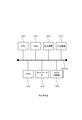
- FIG. 2 is a diagram illustrating a hardware configuration of the setting terminal 3.
- the setting terminal 3 includes a CPU 300, a memory 302, an HDD 304, a network interface 306 (network IF306), a display device 308, a camera control unit 309, and an input device 310, and these configurations are buses. They are connected to each other via 312.
- the CPU 300 is, for example, a central arithmetic unit.
- the memory 302 is, for example, a volatile memory and functions as a main storage device.
- the HDD 304 is, for example, a hard disk drive device, and stores computer programs (for example, the progress management unit 320 and the setting work unit 330 in FIG.
- the network IF306 is an interface for wired or wireless communication.
- the display device 308 is, for example, a liquid crystal display.
- the camera control unit 309 is a control unit that controls the USB camera 42.
- the input device 310 is, for example, a mouse and keyboard touch panel.
- the management server 2A and the resource server 2B have, for example, a hardware configuration in which the camera control unit 309 is excluded from the setting terminal 3.
- FIG. 3 is a diagram illustrating the functional configuration of the management server 2A.
- the setting management program 22 is installed on the management server 2A, and the setting work database 260 (setting work DB 260) and the work reference folder 270 are configured.
- the setting management program 22 is stored in a recording medium such as a CD-ROM, and is installed in the management server 2A via the recording medium.
- a part or all of the setting management program 22 may be realized by hardware such as an ASIC, or may be realized by borrowing a part of the functions of the OS (Operating System).
- the setting work DB 260 stores the setting information of each of the setting target devices 9 and the ledger of the setting target devices 9.
- the work reference folder 270 is a folder that can be referred to by the setting terminal 3, the print control PC 50, and the like, and data files necessary for the setting work and the like are placed therein.
- the setting management program 22 includes a work instruction input unit 220, a work plan formulation unit 222, a setting file registration unit 224, an arrival inspection unit 226, an allocation processing unit 228, a printing processing unit 230, a check sheet processing unit 232, and a process management unit 234. It also has a ledger management unit 236.
- the work instruction input unit 220 takes in the setting information from the customer and registers it in the setting work DB 260.
- the work plan formulation unit 222 creates a mass production plan for the setting work and registers it in the setting work DB 260.
- the setting file registration unit 224 takes in the update date and file size of the setting file registered in the setting work DB 260, and stores the registered setting file (setting file provided by the customer) in the work reference folder 270.
- the arrival inspection unit 226 inputs the result of the arrival inspection of the arrival setting target device 9 (setting target PC 9). Specifically, the arrival inspection unit 226 acquires the manufacturing machine (device identification information) of the device 9 to be set via the handy terminal 54, and registers the acquired manufacturing machine in the device ledger.
- the allocation processing unit 228 allocates the set target device 9 for which the arrival inspection has been completed and the provided setting file. Specifically, the allocation processing unit 228 allocates the setting files matching the models to the setting target device 9 in the order in which the arrival inspection is completed, and associates the manufacturing machine of the device ledger with the individual setting files.
- the print processing unit 230 uses the setting target device 9 for the printing device 52 based on the device identification information.
- Send print data that includes information indicating the person or installation location.
- the print processing unit 230 is an example of a print data providing unit according to the present invention. Specifically, the print processing unit 230 transmits the print data of the label for the outer box on which the individual identification information associated with the manufacturing machine is displayed to the printing device 52A, and manufactures the printing device 52B. The print data of the label for the device housing on which the individual identification information associated with the unit is displayed is transmitted.
- the check sheet processing unit 232 When the check sheet processing unit 232 receives the device identification information (specifically, the manufacturing machine), the check sheet processing unit 232 is an electronic check sheet for inspecting the set target device 9 for which the setting work has been completed, based on the received device identification information. Is read, and the read electronic check sheet is transmitted to the tablet terminal 56.
- the device identification information specifically, the manufacturing machine
- the process control unit 234 manages the process of each setting target device 9 based on the process ID.
- the process ID is updated every time the process is completed.
- the ledger management unit 236 creates a device ledger in which the device identification information acquired by the handy terminal 54 and the unique setting file assigned by the allocation processing unit 228 are associated with each other. More specifically, the ledger management unit 236 includes the manufacturing unit of the setting target device 9 acquired by the handy terminal 54, a unique setting file assigned to the setting target device 9 by the allocation processing unit 228, and this setting.
- a device ledger that is associated with the process ID of the target device 9 is created and updated. The equipment ledger is confirmed as a ledger when all processes are completed.
- the resource server 2B has a DHCP (Dynamic Host Configuration Protocol) server function for performing master cloning to the connected device 9 to be set, and a PXE (Preboot eXecution Environment) server function, and is an automatic setting scenario that performs automatic setting control.
- DHCP Dynamic Host Configuration Protocol
- PXE Preboot eXecution Environment
- FIG. 4 is a diagram illustrating the relationship between the functional configuration of the print control PC 50 and the printing device 52.
- the print control PC 50 has a print information receiving unit 500 that receives print data transmitted from the handy terminal 54 via the web application of the management server 2A, and a printing device that prints according to the received print data. It has a print instruction unit 504 that controls 52, and a check sheet generation unit 502 that generates an electronic check sheet.
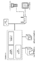
- FIG. 5 is a diagram for explaining the relationship between the functional configuration of the setting terminal 3 and the setting target device 9 loaded on the carriage 4.
- the setting terminal 3 is connected to a plurality of key input control units 40 and a plurality of USB cameras 42 via a USB hub and a USB cable, and these key input control units 40 are connected via a USB cable. It is connected to a plurality of setting target PCs 9.
- the key input control unit 40 includes a serial communication board 400 and a key input microcomputer board 410.
- the serial communication board 400 realizes communication by USB connection.
- the key input microcomputer board 410 is a microcomputer board that emulates keyboard input, and stores a key operation scenario 412 that is a scenario that defines the content, order, and timing of keyboard input.
- the plurality of USB cameras 42 are installed at positions facing the monitors of the plurality of setting target PCs 9 loaded on the carriage 4, and photograph the display of the setting target PC 9.
- the setting terminal 3 has a progress management unit 320 that manages the progress of the setting work of the setting target device 9 (setting target PC 9), and a setting work unit 330 that executes the setting work of the setting target device 9.
- the setting terminal 3 stores an image restoration patch and a master image file for master cloning.
- the progress management unit 320 connects to the plurality of key input control units 40 and the plurality of USB cameras 42 via the USB hub and the USB cable, and manages and displays the progress of the setting work for the plurality of setting target devices 9. Specifically, the progress management unit 320 performs character recognition processing on the image (photographed image taken by the monitor) taken by the USB camera 42, extracts a character string, and based on the extracted character string, Determine the progress of the scenario. For example, the progress management unit 320 performs OCR processing on the image taken by the USB camera 42 (the image taken by the monitor) to extract a character string, and sets in each setting step based on the extracted character string. Determine if the process was completed normally. Further, the progress management unit 320 outputs a warning when the default character string is not extracted by the default timing defined in the scenario.
- the setting work unit 330 is connected to a plurality of key input control units 40 via a USB hub and a USB cable, and controls the input of setting information by the key input control unit 40.
- the key input control unit 40 makes a USB connection to each of the setting target devices 9, and inputs individual setting information in parallel in order according to a scenario.
- the scenario includes the order of information to be entered and the waiting time after entry. Specifically, the key input control unit 40 sequentially inputs the setting information according to the key operation scenario 412.
- a LAN hub and a LAN cable are prepared for the trolley 4, and each setting target device 9 loaded on the trolley 4 uses the LAN hub and the LAN cable to set the setting terminal 3, the resource server 2B, and the management server. It is connected to 2A.
- the setting target device 9 loaded on the trolley 4 receives distribution of a common data file such as a master image via this LAN connection.
- FIG. 6 is a flowchart illustrating the entire process in the setting management system 1.
- the whole process includes an arrival process S10, an unpacking / allocation process S20, a setting work process S30, a label printing process S40, and a packing inspection process S50.
- the unpacking / allocation process S20, the setting work process S30, the label printing process S40, and the packing inspection process S50 are carried out at different locations, and the trolley 4 is moved to carry out these steps.
- the arrival process S10 when the setting target device 9 arrives, the handy terminal 54 is used to acquire the manufacturing number and the pallet number of the setting target device 9 and transmit them to the management server 2.
- the arrival inspection unit 226 of the management server 2 saves the device information (manufacturing machine) received from the handy terminal 54 as a device list in the device ledger in the setting work DB 260, and at the same time, the process control unit 234 stores the process ID as "1". Record as. When the already registered manufacturing machine is read, the arrival inspection unit 226 displays an arrival error on the screen of the handy terminal 54.
- the setting target device 9 for performing the setting work is unpacked, mounted on the trolley 4, and the target trolley bar code and the manufacturing machine of the mounted device are read by the handy terminal 54.
- the manufacturing machine confirms that the receipt processing is performed by this system and the process ID is "1", and if there is no problem, the allocation processing unit 228 of the management server 2 reads the setting file into the setting target device 9
- the process control unit 234 changes the process ID of the target machine to "2". If the process ID is not "1", an allocation error is displayed on the screen of the handy terminal 54.
- the setting target device 9 loaded on the trolley 4 is connected to the setting terminal 3 with a USB cable.
- the setting target device 9 is started WinPE by PXE boot
- the setting terminal 3 acquires the manufacturing number of the setting target device 9 from the BIOS, and the process ID is "2".
- the individual automatic setting of the device 9 to be set is started based on the individual setting information assigned to the acquired manufacturing machine. If the process ID is not "2", a process error is displayed on the progress screen of the setting terminal 3.
- the printing device 52B prints the device housing label and the printing device 52A prints the outer box label as individual identification labels on the set target device 9 for which the setting work S30 has been completed. Attach these labels.
- the handy terminal 54 read the manufacturing machine of the device 9 to be set, confirm that the process ID of the target machine is "4", and if there is no problem, the print processing unit of the management server 2A.
- the 230 provides print data of a label on which individual identification information associated with the manufacturing machine is described in the setting work DB 260 to the printing device 52A and the printing device 52B, and one label is printed for each. If the process ID is not "4", a process error is displayed on the screen of the handy terminal 54.
- the check sheet generation unit 502 After printing, the check sheet generation unit 502 generates the data of the electronic check sheet to be used in the next process and makes it available for download, and the management server 2A (process control unit 234) sets the process ID of the device 9 to be set to ". Change to "5".
- the device 9 to be set with the label attached is moved to the packing work place to carry out the packing work.
- the tablet terminal 56 reads the manufacturing machine of the device 9 to be set, confirms that the process ID of the device 9 to be set is "5", and if there is no problem, checks the electronic check sheet generated in the previous process.
- the sheet generation unit 502 downloads from the management server 2. According to the procedure described on the electronic check sheet, check the packaged items, take a picture of the final packaged state and the state of the attached label with the camera of the tablet terminal 56, obtain evidence, and after the work is completed, go to the management server 2A. Perform the upload process. At this time, the check sheet generation unit 502 confirms whether all the items are checked, and if there is any omission, uploading is not possible. After the upload is completed, the process control unit 234 changes the process ID of the device 9 to be set to "6".
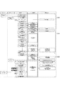
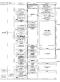
- the setting work step S30 includes an automatic control program activation process (S300), a master cloning preset setting process (S310), a master cloning process (S320), and an OS automatic setting process (S330). ), The BIOS setting process (S340), the BIOS setting location screen shooting process (S350), and the BIOS setting confirmation process (S360). These steps proceed in order, and the progress management unit 320 of the setting terminal 3 displays the progress as "starting" in S300, "setting for BIOS restoration” in S310, and “winPE starting” to "starting in S320". Monitored as “Master restoration”, “OS automatic setting” in S330, “BIOS shipping setting” in S340, "BIOS setting confirmation” to "OK: normal end” in S350, "OK: BIOS confirmation completed” in S360. Display in.
- the operator activates the setting work unit 330 (automatic control program in the figure) from the setting terminal 3.
- the setting work unit 330 connects to the management server 2A, and based on the individual setting information stored in the management server 2A, the definition file "D: ⁇ work ⁇ " used in the subsequent process. "sn.csv" is automatically created. Further, the setting work unit 330 connects to the master image storage folder of the resource server 2B and confirms the difference from the master image stored in the setting terminal 3. If there is a difference, the setting terminal 3 displays an error screen and stops the process.
- the key input control unit 40 starts transmitting the "F2 key" to the setting target PC 9.
- the operator turns on the power of all the setting target PCs 9 for kitting, confirms that the BIOS setting screen is displayed, and then presses the execution button of the automatic control program.
- the progress is displayed on the automatic control program as "starting", and the following processes are executed as control processes of the key input control unit 40.
- the setting work unit 330 (automatic control program) controls the USB camera 42 and photographs the system information screen displayed on the setting target PC 9 in order to record the kitting work trail.
- each USB camera 42 performs a shooting process one by one in order to simplify the connection with each setting target PC and speed up the shooting process.
- the exclusive right management process is executed between the setting work unit 330 (automatic control program) and the key input control unit 40 (commands: startwait, snwait).
- the BIOS settings -Reset the BIOS to factory default-ON network boot ⁇ Turn on secure boot -Save settings and restart
- the setting work unit 330 is in a standby state until it receives start information from the setting target PC 9.
- the key input control unit 40 activates the script (fukugen) corresponding to the process number and controls the F12 key and the cursor key.
- the key input control unit 40 shifts to the Windows PE start standby state and waits for information from the setting work unit 330 (automatic control program).
- the setting target PC 9 started from the network downloads the Windows PE image from the resource server 2B and starts it.
- WindowsPE is started on the setting target PC9, the following is executed by the startup process.
- connection log file (o: ⁇ log.menu ⁇ [type name] ⁇ [serial number] .log)
- Storage of startup completion information file (o: ⁇ [Imgsv] [Port])
- the setting work unit 330 (automatic control program) acquires the manufacturing machine number described in the file and sends it to the management server 2A. Make the following inquiries.
- the key input control unit 40 transmits the following keys to the setting target PC 9. After transmission, it waits until it receives "restore completion" from the setting work unit 330 (automatic control program).
- setting terminal 3 o: ⁇ [server management number] start.bat
- master cloning p: ⁇ restore.bat
- p ⁇ restore.bat
- the key input control unit 40 key-transmits " ⁇ 192.168.5.11 ⁇ pqs ⁇ setpc.vbs" to the setting target PC 40.
- the setting target PC9 starts the restored OS and executes setpc.vbs. Setpc.vbs automates keyboard and mouse operations Scenarios are launched and automatic settings are performed on the OS.
- the setting work unit 330 loops and waits until "z_end_ [port number]” or "z_error_ [port number]” is generated in the "koutei” folder.
- the key input control unit 40 loops and waits until "y" is transmitted from the setting terminal 3.
- the setting target PC 9 generates a "z_end_ [port number]” file in the "koutei” folder when the automatic setting of the OS is completed.
- the progress management unit 320 changes the progress display to [BIOS shipping setting], and the setting main unit 330 sends "y" to the key input control unit 40 to notify that the automation of the OS is completed.
- the setting target PC9 generates "z_error_ [port number]" in the "koutei” folder when an error occurs during the setting work.
- the progress management unit 320 of the setting terminal 3 confirms the existence of "z_error_ [port number]” in the "koutei” folder, an error is displayed in the progress display, and the setting work unit 330 stops the work.
- the setting target PC 9 is in a state where the BIOS screen is opened by operating the F2 key.
- the key input control unit 40 transmits "s" to the setting terminal 3 to confirm the usage right in order to acquire the usage right of the USB camera 42 for photographing the BIOS setting state. If the setting terminal 3 is not used in another port, the setting terminal 3 returns "a" to the key input control unit 40 and passes the exclusive use right of the USB camera 42.
- the key input control unit 40 repeats key transmission and sets the factory shipment of the BIOS.
- the key input control unit 40 When the key input control unit 40 makes a change, the key input control unit 40 transmits a shooting request "o" to the setting terminal 3.
- the setting terminal 3 uses the USB camera 42 to shoot the setting screen of the setting target PC 9, and then returns the shooting completion "p" to the key input control unit 40.
- the setting target PC 9 opens the BIOS screen by operating the F2 key.
- the key input control unit 40 transmits "s" to the setting terminal 3 to confirm the usage right in order to acquire the usage right of the USB camera 42. If the setting terminal 3 is not used in another port, the setting terminal 3 returns "a" to the key input control unit 40 and passes the exclusive use right of the USB camera 42.
- the key input control unit 40 repeats key transmission and inputs the BIOS password implemented in the BIOS shipping settings.
- the key input control unit 40 transmits a shooting request "o" to the setting terminal 3 with the BIOS screen open.
- the setting terminal 3 uses the USB camera 42 to shoot the setting screen of the setting target PC 9, and then returns a shooting completion "p".
- the key input control unit 40 turns off the power of the setting target PC 9 from the BIOS and then transmits "j" to the setting terminal 3, the setting terminal 3 releases the exclusive right of the USB camera 42.
- the progress management unit 320 of the setting terminal 3 performs OCR processing on the photograph taken during the BIOS setting, converts it into text, and confirms whether the setting content is correct. .. If there is a reading defect in the OCR process, the corresponding photo is displayed on the screen of the setting terminal 3, and a dialog asking the operator to judge the quality is displayed.
- the setting terminal 3 collects the MAC address of the setting target PC 9 from the work log and registers it in the setting work DB 260 of the management server 2A. The photo of the BIOS screen and the log file acquired by OS automation are moved to the work log storage folder of the resource server 2B.
- the process management unit 234 of the management server 2A changes the process ID of this manufacturing machine to "4" and sets it.
- the progress management unit 320 of the terminal 3 changes the progress display to "OK: BIOS confirmation completed”. This completes the setting work process (S30).
- FIG. 9 is a flowchart illustrating the label printing step S40 in more detail.
- the input state of the trolley 4 is confirmed at the handy terminal 54, and if there is no problem, the manufacturing machine is input on the input screen of the manufacturing machine. If the identification information of the trolley 4 is not input, the input screen of the workbench identification information is displayed, and after the input, the input screen of the manufacturing machine is displayed.
- the management server 2A executes the input value check, the extraction of the manufacturing machine, and the worker check to search the data.
- the process ID is confirmed from the searched development data, a CSV file containing items to be printed is created, and the process control unit 234 changes the process ID of the device 9 to be set to "5".
- the print control PC 50 detects the CSV file, detects the model name from the file name, confirms whether the model name matches the model name set in the print instruction unit 504, imports the CSV file into the work table, and counts the number of data items. To confirm. When the number of data items is 0, the print control PC 50 imports the CSV three times, and when the number of data items is three or more, an error message is displayed. When the number of data items is other than 0, the print control PC 50 causes the printing device 52A and the printing device 52B to print the label for the outer box and the label for the device housing, outputs an electronic check sheet as a PDF file, and imports the data. Store the printed CSV file in the OK folder.
- FIG. 10 is a flowchart illustrating the packing inspection step S50 in more detail.
- the management server 2A searches the electronic check sheet from the entered employee number and manufacturing machine, and confirms the presence or absence. If there is no electronic check sheet, an error message will be displayed. If there is a check sheet, search the device data from the entered manufacturing machine and confirm the existence. If there is no device data, an error message is displayed. If there is device data, the worker data is searched from the entered employee number. If there is no worker data, an error message will be displayed. If there is worker data, the device data is searched and the process ID of the setting target PC 9 is changed to "6". Search if the check sheet is in use, and if it is in use, display a guidance message. If it can be used, the tablet terminal 56 downloads the target electronic check sheet from the management server 2A.
- the "upload" button is pressed on the tablet terminal 56.
- the tablet terminal 56 searches for a user in use, acquires a user ID, and uploads an electronic check sheet to the management server 2. If the user ID cannot be obtained, an error log is output and processing is stopped.
- the check sheet processing unit 232 of the management server 2 confirms that the electronic check sheet has been uploaded successfully, and if there is no problem, moves the file to the download folder so that the checked state can be downloaded. When an upload failure or a move failure to the download folder occurs, the check sheet processing unit 232 outputs an error log and stops.
- the process control unit 234 changes the process ID to "7" when the check status of the electronic check sheet for which the movement is completed is analyzed and all the movements are completed.
- the tablet terminal 56 deletes the electronic check sheet data on its own device.
- the setting work of a plurality of setting target PCs 9 can be carried out in parallel in an assembly line.
- the setting information set in the setting target PC 9 is individual, and a label that can distinguish this is attached.
- the setting work of the setting target PC 9 is automated, and it is sufficient for the operator to respond only when an error or the like occurs. Further, according to the setting management system 1, the progress of the work can be grasped in real time at the kitting site where unpacking, allocation, setting, packing and the like are carried out in an assembly line.
Landscapes
- Engineering & Computer Science (AREA)
- Software Systems (AREA)
- Theoretical Computer Science (AREA)
- Physics & Mathematics (AREA)
- General Physics & Mathematics (AREA)
- General Engineering & Computer Science (AREA)
- Computer Security & Cryptography (AREA)
- Manufacturing & Machinery (AREA)
- Business, Economics & Management (AREA)
- Multimedia (AREA)
- Computer Vision & Pattern Recognition (AREA)
- Economics (AREA)
- Health & Medical Sciences (AREA)
- General Health & Medical Sciences (AREA)
- Human Resources & Organizations (AREA)
- Marketing (AREA)
- Primary Health Care (AREA)
- Strategic Management (AREA)
- Tourism & Hospitality (AREA)
- General Business, Economics & Management (AREA)
- Automation & Control Theory (AREA)
- Quality & Reliability (AREA)
- Management, Administration, Business Operations System, And Electronic Commerce (AREA)
- General Factory Administration (AREA)
Abstract
機器の設定作業を効率化する設定管理システムを提供する。 設定端末は、設定対象機器に関する設定処理のシナリオを格納する格納部と、設定対象機器に対してUSB接続して、情報を入力する入力部と、前記入力部による入力のタイミングと、前記格納部に格納されたシナリオとに基づいて、設定処理のシナリオの進捗を判定する進捗判定部と、前記進捗判定部により判定されたシナリオの進捗に従って、前記入力部を介して、設定情報を設定対象機器に入力する設定作業部とを有する。
Description
本発明は、設定端末、設定方法、及びプログラムに関する。
例えば、特許文献1には、対象PCの設定作業を実行する一連のマウス操作を予め記述した制御情報を解析し、解析結果に基づいて、対象PCに対するマウス操作を行うための擬似的な操作信号を生成し、生成した操作信号を対象装置に送信することで、対象PCに対するマウス操作を実行する支援装置100が開示されている。
また、特許文献2には、複数の起動プログラム17を格納する格納部16と、複数の情報処理装置3のうちの1つの情報処理装置3の構成情報を取得する構成情報取得部32と、取得した構成情報に基づいて格納部16に格納されている複数の起動プログラム17から、1つの情報処理装置3に対応する起動プログラム17を選択する選択部33と、選択部33によって選択された起動プログラム17を1つの情報処理装置3に送信する送信部34とを有する管理装置2が開示されている。
また、特許文献3には、短時間での人手キー/マウス入力の受け付け場面で、画面比較/確認装置12と制御装置2とが協動して人手に代わって自動的にキー/マウス入力を行う情報処理装置が開示されている。
また、特許文献2には、複数の起動プログラム17を格納する格納部16と、複数の情報処理装置3のうちの1つの情報処理装置3の構成情報を取得する構成情報取得部32と、取得した構成情報に基づいて格納部16に格納されている複数の起動プログラム17から、1つの情報処理装置3に対応する起動プログラム17を選択する選択部33と、選択部33によって選択された起動プログラム17を1つの情報処理装置3に送信する送信部34とを有する管理装置2が開示されている。
また、特許文献3には、短時間での人手キー/マウス入力の受け付け場面で、画面比較/確認装置12と制御装置2とが協動して人手に代わって自動的にキー/マウス入力を行う情報処理装置が開示されている。
機器の設定作業を効率化する設定管理システムを提供することを目的とする。
本発明に係る設定端末は、設定対象機器に関する設定処理のシナリオを格納する格納部と、設定対象機器に対してUSB接続して、情報を入力する入力部と、前記入力部による入力のタイミングと、前記格納部に格納されたシナリオとに基づいて、設定処理のシナリオの進捗を判定する進捗判定部と、前記進捗判定部により判定されたシナリオの進捗に従って、前記入力部を介して、設定情報を設定対象機器に入力する設定作業部とを有する。
好適には、前記設定情報は、オペレーティングシステムの起動前に入力する情報を含み、前記入力部は、キーボード入力をエミュレートして、前記設定対象機器に設定情報を入力する。
好適には、前記設定対象機器の表示を撮影する撮影部をさらに有し、前記進捗判定部は、前記撮影部による撮影画像に基づいて、設定処理の進捗を判定する。
好適には、前記入力部は、複数の入力装置を含み、前記撮影部は、複数の撮影装置を含み、前記設定作業部は、複数の前記入力装置を介して、複数の設定対象機器に対して、並行して設定情報の入力を行い、前記進捗判定部は、複数の撮影装置それぞれによる撮影画像に基づいて、複数の設定対象機器それぞれの設定処理の進捗を判定する。
好適には、前記入力部は、複数の入力装置を含み、前記撮影部は、複数の撮影装置を含み、前記設定作業部は、複数の前記入力装置を介して、複数の設定対象機器に対して、並行して設定情報の入力を行い、前記進捗判定部は、複数の撮影装置それぞれによる撮影画像に基づいて、複数の設定対象機器それぞれの設定処理の進捗を判定する。
好適には、機器識別情報を前記設定対象機器から取得する識別情報取得部をさらに有し、前記設定作業部は、前記入力部を介して、前記識別情報取得部により取得された機器識別情報それぞれに固有の設定情報を、前記設定対象機器に入力する。
好適には、LANケーブルを介して、前記設定対象機器に接続するネットワーク接続部をさらに有し、前記設定作業部は、前記入力部を介して、複数の設定対象機器それぞれに固有の設定情報を入力し、前記設定作業部は、前記ネットワーク接続部を介して、マスタイメージを複数の設定対象機器に配布する。
好適には、前記進捗判定部は、前記撮影部により撮影された画像に対して文字認識処理を施して、文字列を抽出し、抽出された文字列に基づいて、シナリオの進捗を判定する。
好適には、前記進捗判定部は、前記格納部に格納されたシナリオで定義された既定のタイミングまでに、既定の文字列が抽出されなかった場合に、警告を出力する。
好適には、前記進捗判定部は、前記格納部に格納されたシナリオで定義された既定のタイミングまでに、既定の文字列が抽出されなかった場合に、警告を出力する。
また、本発明に係る設定方法は、設定対象機器に対してUSB接続して、設定情報を入力する第1の入力ステップと、前記第1の入力ステップによる入力のタイミングと、設定対象機器に関する設定処理のシナリオとに基づいて、設定処理のシナリオの進捗を判定する進捗判定ステップと、前記進捗判定ステップにより判定されたシナリオの進捗に従って、次の設定情報を、前記設定対象機器に対して入力する第2の入力ステップとを有する。
また、本発明に係るプログラムは、設定対象機器に対してUSB接続して、設定情報を入力する第1の入力ステップと、前記第1の入力ステップによる入力のタイミングと、設定対象機器に関する設定処理のシナリオとに基づいて、設定処理のシナリオの進捗を判定する進捗判定ステップと、前記進捗判定ステップにより判定されたシナリオの進捗に従って、次の設定情報を、前記設定対象機器に対して入力する第2の入力ステップとをコンピュータに実行させる。
機器の設定作業を効率化することができる。
以下、本発明の実施形態を、図面を参照して説明する。
図1は、設定管理システム1の全体構成を例示する図である。
図1に例示するように、設定管理システム1は、管理サーバ2Aと、資源サーバ2Bと、設定端末3と、台車4と、印刷制御パーソナルコンピュータ(印刷制御PC)50と、印刷装置52と、ハンディターミナル54と、タブレット端末56とを有し、これらがネットワークを介して互いに接続している。ネットワークは、例えば、LANケーブルと、LAN(Local Area Network)ハブ60と、無線アクセスポイント(無線AP)62とで構成されている。
図1は、設定管理システム1の全体構成を例示する図である。
図1に例示するように、設定管理システム1は、管理サーバ2Aと、資源サーバ2Bと、設定端末3と、台車4と、印刷制御パーソナルコンピュータ(印刷制御PC)50と、印刷装置52と、ハンディターミナル54と、タブレット端末56とを有し、これらがネットワークを介して互いに接続している。ネットワークは、例えば、LANケーブルと、LAN(Local Area Network)ハブ60と、無線アクセスポイント(無線AP)62とで構成されている。
管理サーバ2Aは、設定作業に必要な設定情報及び機器情報を提供するコンピュータ端末である。例えば、管理サーバ2は、設定端末3による設定作業と、印刷装置52による印刷作業とを含む全体工程を管理する。
資源サーバ2Bは、インストール作業に必要な資源(マスタイメージ及びインストールアプリ)を保存するコンピュータ端末である。なお、管理サーバ2A及び資源サーバ2Bが単一のコンピュータ端末で実現されてもよい。
設定端末3は、コンピュータ端末であり、管理サーバ2からの指示に応じて、台車4に積載された複数の設定対象機器9(設定対象パーソナルコンピュータ9)に対する設定作業を並行して実施する。
資源サーバ2Bは、インストール作業に必要な資源(マスタイメージ及びインストールアプリ)を保存するコンピュータ端末である。なお、管理サーバ2A及び資源サーバ2Bが単一のコンピュータ端末で実現されてもよい。
設定端末3は、コンピュータ端末であり、管理サーバ2からの指示に応じて、台車4に積載された複数の設定対象機器9(設定対象パーソナルコンピュータ9)に対する設定作業を並行して実施する。
台車4は、複数の設定対象機器9を積載する台車である。例えば、台車4は、キャスター付きの台車であり、複数の設定対象機器9を積載した状態で移動させることができる。本例では、台車4は、8台の設定対象PC9を積載可能であり、少なくとも、開梱場所、設定端末3の近傍、印刷装置52の近傍、検査場所、及び、梱包場所に移動する。
また、台車4には、複数のキー入力制御部40及び複数のUSBカメラ42が用意されており、USBハブ及びUSBケーブルを介して、設定端末3に接続している。これらのキー入力制御部40が1対1で設定対象PC9にUSB接続しており、複数の設定対象PC9のモニタに対向する位置にUSBカメラ42が設置されている。
また、台車4には、複数のキー入力制御部40及び複数のUSBカメラ42が用意されており、USBハブ及びUSBケーブルを介して、設定端末3に接続している。これらのキー入力制御部40が1対1で設定対象PC9にUSB接続しており、複数の設定対象PC9のモニタに対向する位置にUSBカメラ42が設置されている。
印刷制御PC50は、印刷装置52による印刷処理を制御するコンピュータ端末であり、管理サーバ2Aから提供される印刷データに基づいて、印刷装置52に印刷処理を実行させる。本例では、印刷装置52Aが、印刷制御PC50の制御に応じて、設定対象機器9を梱包する外箱に貼付するためのラベルを印刷する。印刷装置52Bが、印刷制御PC50の制御に応じて、設定対象機器9の筐体に貼付するためのラベルを印刷する。
ハンディターミナル54は、設定対象機器9の識別情報(製造号機)を入力する携帯型コンピュータ端末である。例えば、ハンディターミナル54は、入荷工程、開梱・引当工程、印刷工程、検査工程、及び梱包工程において、設定対象機器9の製造号機を読み取る。
タブレット端末56は、設定対象機器9の検査を行う検査工程において、検査担当者が検査を行った結果を入力するタブレット型コンピュータ端末である。
タブレット端末56は、設定対象機器9の検査を行う検査工程において、検査担当者が検査を行った結果を入力するタブレット型コンピュータ端末である。
上記設定管理システム1は、例えば、短納期かつ大規模のパソコン設定作業が発生し、短期間で大量に (例えば、2~5か月間で数千台から数万台)の設定作業を実施する場合等に有効である。同一の物を大量生産する方法として、ライン生産方式が知られている。ライン生産方式では、ベルトコンベア等で加工対象物を流しながら、加工を行うため、個別対応に不向きであった。特に、パソコンの設定作業では、設定情報が多種となり、外観から区別できないため、流れ作業で個別対応を採ることが困難であった。
また、これまでのパソコンの設定作業では、BIOS設定、マスタイメージの復元、オペレーティングシステム(OS)個別設定の工程があり、効率化を実現するにあたり、以下の課題があった。
OSの設定は、RPA技術活用で自動化可能であるが、マスタイメージの復元やBIOS設定は、物理的なキーボード入力作業が必要なため、手作業が発生してしまう。
再起動時のログオン操作など、OS上の自動化では対応できない部分ついて手作業が発生する。
一対一の制御しかできないため全体の状況が監視できない。また作業スペースが必要になる。
BIOS設定結果を電子的に確認する手段がなく、目視確認が必要である。
OSの設定は、RPA技術活用で自動化可能であるが、マスタイメージの復元やBIOS設定は、物理的なキーボード入力作業が必要なため、手作業が発生してしまう。
再起動時のログオン操作など、OS上の自動化では対応できない部分ついて手作業が発生する。
一対一の制御しかできないため全体の状況が監視できない。また作業スペースが必要になる。
BIOS設定結果を電子的に確認する手段がなく、目視確認が必要である。
入荷から出荷までの各工程の作業進捗を把握しコントロールするためには、以下の課題があった。
作業進捗が工程毎の管理になっているため、各工程で連動させ全体を把握する必要がある。
進捗状況の確認を手動でおこなっており実際の状況とのタイムラグが発生し、リアルタイムに状況を把握するのが難しい。
作業進捗が工程毎の管理になっているため、各工程で連動させ全体を把握する必要がある。
進捗状況の確認を手動でおこなっており実際の状況とのタイムラグが発生し、リアルタイムに状況を把握するのが難しい。
そこで、本実施形態の設定管理システム1では、パソコン設定作業の自動化と複数台同時制御については、設定端末3からパソコン設定作業の各工程について以下のコントロールを行うことで実現を果たした。
<自動設定>
物理的なキー入力と同等の処理をプログラミング可能なマイコンボード(キー入力制御部40)を活用することにより、これまで手入力していた全ての項目の入力自動化を実現し、BIOS設定からマスタイメージ復元、OSの設定まですべてを、設定対象PC9の電源を投入するだけで自動設定を実現した。
BIOSの設定結果等、目視が必要であった作業は、自動設定中の画面をUSBカメラ42で撮影し、OCR技術の活用により、設定結果をテキスト化し自動判定を実現した。
<複数台同時制御>
各工程の状況は、設定端末3で監視し進捗状況を把握する。
自動設定でエラーが発生した場合は設定端末3で監視し検知する。
各工程の進捗状況を把握するために、管理サーバ2Aが、設定対象PC9単位で工程ID(工程の識別情報)を付与し、工程変更時に各工程から自動的に、工程ID情報を受信するしくみを作った。
<自動設定>
物理的なキー入力と同等の処理をプログラミング可能なマイコンボード(キー入力制御部40)を活用することにより、これまで手入力していた全ての項目の入力自動化を実現し、BIOS設定からマスタイメージ復元、OSの設定まですべてを、設定対象PC9の電源を投入するだけで自動設定を実現した。
BIOSの設定結果等、目視が必要であった作業は、自動設定中の画面をUSBカメラ42で撮影し、OCR技術の活用により、設定結果をテキスト化し自動判定を実現した。
<複数台同時制御>
各工程の状況は、設定端末3で監視し進捗状況を把握する。
自動設定でエラーが発生した場合は設定端末3で監視し検知する。
各工程の進捗状況を把握するために、管理サーバ2Aが、設定対象PC9単位で工程ID(工程の識別情報)を付与し、工程変更時に各工程から自動的に、工程ID情報を受信するしくみを作った。
図2は、設定端末3のハードウェア構成を例示する図である。
図2に例示するように、設定端末3は、CPU300、メモリ302、HDD304、ネットワークインタフェース306(ネットワークIF306)、表示装置308、カメラ制御部309、及び入力装置310を有し、これらの構成はバス312を介して互いに接続している。
CPU300は、例えば、中央演算装置である。
メモリ302は、例えば、揮発性メモリであり、主記憶装置として機能する。
HDD304は、例えば、ハードディスクドライブ装置であり、不揮発性の記録装置としてコンピュータプログラム(例えば、図5の進捗管理部320及び設定作業部330)やその他のデータファイルを格納する。
ネットワークIF306は、有線又は無線で通信するためのインタフェースである。
表示装置308は、例えば、液晶ディスプレイである。
カメラ制御部309は、USBカメラ42を制御する制御部である。
入力装置310は、例えば、マウス及びキーボードタッチパネルである。
なお、管理サーバ2A及び資源サーバ2Bは、例えば、設定端末3からカメラ制御部309を除外したハードウェア構成をとる。
図2に例示するように、設定端末3は、CPU300、メモリ302、HDD304、ネットワークインタフェース306(ネットワークIF306)、表示装置308、カメラ制御部309、及び入力装置310を有し、これらの構成はバス312を介して互いに接続している。
CPU300は、例えば、中央演算装置である。
メモリ302は、例えば、揮発性メモリであり、主記憶装置として機能する。
HDD304は、例えば、ハードディスクドライブ装置であり、不揮発性の記録装置としてコンピュータプログラム(例えば、図5の進捗管理部320及び設定作業部330)やその他のデータファイルを格納する。
ネットワークIF306は、有線又は無線で通信するためのインタフェースである。
表示装置308は、例えば、液晶ディスプレイである。
カメラ制御部309は、USBカメラ42を制御する制御部である。
入力装置310は、例えば、マウス及びキーボードタッチパネルである。
なお、管理サーバ2A及び資源サーバ2Bは、例えば、設定端末3からカメラ制御部309を除外したハードウェア構成をとる。
図3は、管理サーバ2Aの機能構成を例示する図である。
図3に例示するように、管理サーバ2Aには、設定管理プログラム22がインストールされ、設定作業データベース260(設定作業DB260)及び作業参照フォルダ270が構成されている。設定管理プログラム22は、例えば、CD-ROM等の記録媒体に格納されており、この記録媒体を介して、管理サーバ2Aにインストールされる。
なお、設定管理プログラム22の一部又は全部は、ASICなどのハードウェアにより実現されてもよく、また、OS(Operating System)の機能を一部借用して実現されてもよい。
設定作業DB260は、設定対象機器9それぞれの設定情報、及び、設定対象機器9の台帳を格納する。
作業参照フォルダ270は、設定端末3及び印刷制御PC50等が参照できるフォルダであり、設定作業等で必要なデータファイルが置かれる。
図3に例示するように、管理サーバ2Aには、設定管理プログラム22がインストールされ、設定作業データベース260(設定作業DB260)及び作業参照フォルダ270が構成されている。設定管理プログラム22は、例えば、CD-ROM等の記録媒体に格納されており、この記録媒体を介して、管理サーバ2Aにインストールされる。
なお、設定管理プログラム22の一部又は全部は、ASICなどのハードウェアにより実現されてもよく、また、OS(Operating System)の機能を一部借用して実現されてもよい。
設定作業DB260は、設定対象機器9それぞれの設定情報、及び、設定対象機器9の台帳を格納する。
作業参照フォルダ270は、設定端末3及び印刷制御PC50等が参照できるフォルダであり、設定作業等で必要なデータファイルが置かれる。
設定管理プログラム22は、作業指示入力部220、作業計画策定部222、設定ファイル登録部224、入荷検品部226、引当処理部228、印刷処理部230、チェックシート処理部232、工程管理部234、及び台帳管理部236を有する。
設定管理プログラム22において、作業指示入力部220は、顧客からの設定情報を取り込み、設定作業DB260に登録する。
作業計画策定部222は、設定作業の量産計画を作成し、設定作業DB260に登録する。
設定ファイル登録部224は、設定作業DB260に登録された設定ファイルの更新日とファイルサイズを取り込み、登録された設定ファイル(顧客から提供された設定ファイル)を作業参照フォルダ270に保管する。
設定管理プログラム22において、作業指示入力部220は、顧客からの設定情報を取り込み、設定作業DB260に登録する。
作業計画策定部222は、設定作業の量産計画を作成し、設定作業DB260に登録する。
設定ファイル登録部224は、設定作業DB260に登録された設定ファイルの更新日とファイルサイズを取り込み、登録された設定ファイル(顧客から提供された設定ファイル)を作業参照フォルダ270に保管する。
入荷検品部226は、入荷した設定対象機器9(設定対象PC9)の入荷検品の結果を入力する。具体的には、入荷検品部226は、ハンディターミナル54を介して、設定対象機器9の製造号機(機器識別情報)を取得し、取得された製造号機を機器台帳に登録する。
引当処理部228は、入荷検品が完了した設定対象機器9と、提供された設定ファイルとを引き当てる。具体的には、引当処理部228は、入荷検品が完了した順に、機種が一致する設定ファイルを設定対象機器9に割り当て、機器台帳の製造号機と、個別の設定ファイルとを関連付ける。
引当処理部228は、入荷検品が完了した設定対象機器9と、提供された設定ファイルとを引き当てる。具体的には、引当処理部228は、入荷検品が完了した順に、機種が一致する設定ファイルを設定対象機器9に割り当て、機器台帳の製造号機と、個別の設定ファイルとを関連付ける。
印刷処理部230は、印刷装置52に関連付けて機器識別情報(具体的には、製造号機)を受信すると、この印刷装置52に対して、機器識別情報に基づいて、この設定対象機器9の使用者又は設置場所を示す情報が含まれた印刷データを送信する。印刷処理部230は、本発明に係る印刷データ提供部の一例である。具体的には、印刷処理部230は、印刷装置52Aに対して、製造号機に関連付けられた個体識別情報が表示された外箱用ラベルの印刷データを送信し、印刷装置52Bに対して、製造号機に関連付けられた個体識別情報が表示された装置筐体用ラベルの印刷データを送信する。
チェックシート処理部232は、機器識別情報(具体的には、製造号機)を受信すると、受信した機器識別情報に基づいて、設定作業が完了した設定対象機器9の検査を行うための電子チェックシートを読み出し、読み出された電子チェックシートをタブレット端末56に送信する。
工程管理部234は、工程IDに基づいて、各設定対象機器9の工程を管理する。工程IDは、工程が完了する度毎に更新される。
台帳管理部236は、ハンディターミナル54により取得された機器識別情報と、引当処理部228により引き当てられた固有の設定ファイルとを互いに関連付けた機器台帳を作成する。より具体的には、台帳管理部236は、ハンディターミナル54により取得された設定対象機器9の製造号機と、この設定対象機器9に引当処理部228により引き当てられた固有の設定ファイルと、この設定対象機器9の工程IDとを互いに関連付けた機器台帳を作成し更新する。機器台帳は、全ての工程が完了した時に、台帳として確定する。
台帳管理部236は、ハンディターミナル54により取得された機器識別情報と、引当処理部228により引き当てられた固有の設定ファイルとを互いに関連付けた機器台帳を作成する。より具体的には、台帳管理部236は、ハンディターミナル54により取得された設定対象機器9の製造号機と、この設定対象機器9に引当処理部228により引き当てられた固有の設定ファイルと、この設定対象機器9の工程IDとを互いに関連付けた機器台帳を作成し更新する。機器台帳は、全ての工程が完了した時に、台帳として確定する。
資源サーバ2Bは、接続された設定対象機器9にマスタクローニングを行うためのDHCP(Dynamic Host Configuration Protocol)サーバ機能と、PXE(Preboot eXecution Environment)サーバ機能とを備え、自動設定制御を行う自動設定シナリオフォルダを有する。また、各資源の保管先として、作業ログ保管フォルダ、工程管理フォルダ、インストール資源フォルダ、及び、マスタイメージ保管フォルダが資源サーバ2Bに用意されている。
図4は、印刷制御PC50の機能構成と、印刷装置52との関係を説明する図である。
図4に示すように、印刷制御PC50は、ハンディターミナル54から管理サーバ2Aのウェブアプリ経由で送信されてくる印刷データを受信する印刷情報受信部500と、受信した印刷データに従って印刷するよう印刷装置52を制御する印刷指示部504と、電子チェックシートを生成するチェックシート生成部502とを有する。
図4に示すように、印刷制御PC50は、ハンディターミナル54から管理サーバ2Aのウェブアプリ経由で送信されてくる印刷データを受信する印刷情報受信部500と、受信した印刷データに従って印刷するよう印刷装置52を制御する印刷指示部504と、電子チェックシートを生成するチェックシート生成部502とを有する。
図5は、設定端末3の機能構成と、台車4に積載された設定対象機器9との関係を説明する図である。
図5に示すように、設定端末3は、USBハブ及びUSBケーブルを介して複数のキー入力制御部40及び複数のUSBカメラ42に接続し、これらのキー入力制御部40は、USBケーブルを介して複数の設定対象PC9に接続している。
キー入力制御部40は、シリアル通信ボード400と、キー入力マイコンボード410とを有する。シリアル通信ボード400は、USB接続での通信を実現する。キー入力マイコンボード410は、キーボード入力をエミュレートするマイコンボードであり、キーボード入力の内容、順序及びタイミングを定義したシナリオであるキー操作シナリオ412を格納している。
複数のUSBカメラ42は、台車4に積載された複数の設定対象PC9のモニタに対向する位置に設置され、設定対象PC9の表示を撮影する。
図5に示すように、設定端末3は、USBハブ及びUSBケーブルを介して複数のキー入力制御部40及び複数のUSBカメラ42に接続し、これらのキー入力制御部40は、USBケーブルを介して複数の設定対象PC9に接続している。
キー入力制御部40は、シリアル通信ボード400と、キー入力マイコンボード410とを有する。シリアル通信ボード400は、USB接続での通信を実現する。キー入力マイコンボード410は、キーボード入力をエミュレートするマイコンボードであり、キーボード入力の内容、順序及びタイミングを定義したシナリオであるキー操作シナリオ412を格納している。
複数のUSBカメラ42は、台車4に積載された複数の設定対象PC9のモニタに対向する位置に設置され、設定対象PC9の表示を撮影する。
設定端末3は、設定対象機器9(設定対象PC9)の設定作業の進捗を管理する進捗管理部320と、設定対象機器9の設定作業を実行する設定作業部330とを有する。設定端末3は、マスタクローニングのためのイメージ復元パッチ及びマスタイメージファイルを格納する。
進捗管理部320は、USBハブ及びUSBケーブルを介して複数のキー入力制御部40及び複数のUSBカメラ42に接続し、複数の設定対象機器9に対する設定作業の進捗を管理し、表示する。具体的には、進捗管理部320は、USBカメラ42により撮影された画像(モニタの撮影画像)に対して文字認識処理を施して、文字列を抽出し、抽出された文字列に基づいて、シナリオの進捗を判定する。例えば、進捗管理部320は、USBカメラ42により撮影された画像(モニタの撮影画像)に対してOCR処理を施して文字列を抽出し、抽出された文字列に基づいて、各設定ステップにおける設定処理が正常に完了したか否かを判定する。
また、進捗管理部320は、シナリオで定義された既定のタイミングまでに、既定の文字列が抽出されなかった場合に、警告を出力する。
また、進捗管理部320は、シナリオで定義された既定のタイミングまでに、既定の文字列が抽出されなかった場合に、警告を出力する。
設定作業部330は、USBハブ及びUSBケーブルを介して複数のキー入力制御部40に接続し、キー入力制御部40による設定情報の入力を制御する。
キー入力制御部40は、設定対象機器9それぞれに対してUSB接続し、シナリオに従って、順に個別の設定情報を並行して入力する。シナリオには、入力すべき情報の順序と、入力後の待機時間とが含まれている。具体的には、キー入力制御部40は、キー操作シナリオ412に従って、設定情報を順に入力する。
キー入力制御部40は、設定対象機器9それぞれに対してUSB接続し、シナリオに従って、順に個別の設定情報を並行して入力する。シナリオには、入力すべき情報の順序と、入力後の待機時間とが含まれている。具体的には、キー入力制御部40は、キー操作シナリオ412に従って、設定情報を順に入力する。
台車4には、LANハブ及びLANケーブルが用意されており、台車4に積載された各設定対象機器9は、このLANハブ及びLANケーブルを介して、設定端末3、資源サーバ2B、及び管理サーバ2Aと接続されている。台車4に積載された設定対象機器9は、このLAN接続を介して、マスタイメージ等の共通するデータファイルの配信を受ける。
図6は、設定管理システム1における全体工程を説明するフローチャートである。
図6に示すように、全体工程は、入荷工程S10と、開梱・引当工程S20と、設定作業工程S30と、ラベル印刷工程S40と、梱包検査工程S50とを含む。例えば、開梱・引当工程S20、設定作業工程S30、ラベル印刷工程S40、及び、梱包検査工程S50は、それぞれ異なる場所で実施され、台車4を移動させて、これらの工程を実施する。
入荷工程S10において、設定対象機器9の入荷時に、ハンディターミナル54を使用し、設定対象機器9の製造号機と、パレット番号を取得し、管理サーバ2に送信する。管理サーバ2の入荷検品部226は、ハンディターミナル54から受信した機器情報(製造号機)を設定作業DB260内の機器台帳に装置一覧として保存し、同時に、工程管理部234は、工程IDを「1」 として記録する。すでに登録済みの製造号機を読み込んだ場合は、入荷検品部226は、ハンディターミナル54の画面に入荷エラーを表示させる。
図6に示すように、全体工程は、入荷工程S10と、開梱・引当工程S20と、設定作業工程S30と、ラベル印刷工程S40と、梱包検査工程S50とを含む。例えば、開梱・引当工程S20、設定作業工程S30、ラベル印刷工程S40、及び、梱包検査工程S50は、それぞれ異なる場所で実施され、台車4を移動させて、これらの工程を実施する。
入荷工程S10において、設定対象機器9の入荷時に、ハンディターミナル54を使用し、設定対象機器9の製造号機と、パレット番号を取得し、管理サーバ2に送信する。管理サーバ2の入荷検品部226は、ハンディターミナル54から受信した機器情報(製造号機)を設定作業DB260内の機器台帳に装置一覧として保存し、同時に、工程管理部234は、工程IDを「1」 として記録する。すでに登録済みの製造号機を読み込んだ場合は、入荷検品部226は、ハンディターミナル54の画面に入荷エラーを表示させる。
開梱・引当工程S20において、設定作業を実施する設定対象機器9を開梱し、台車4に搭載し、専用台車バーコード及び搭載した機器の製造号機をハンディターミナル54で読み取る事により、対象の製造号機が、本システムにより、入荷処理され工程IDが「1」になっている事を確認し、問題なければ、管理サーバ2の引当処理部228は、設定ファイルを、読み込んだ設定対象機器9の製造号機に引き当て、工程管理部234は、この対象号機の工程IDを「2」に変更する。 工程IDが「1」でない場合は、ハンディターミナル54の画面に引き当てエラーを表示する。
設定作業工程S30において、台車4に積載された設定対象機器9を設定端末3にUSBケーブルで接続する。設定対象機器9の電源を投入すると、設定対象機器9をPXEブートにてWinPE起動させ、設定端末3は、BIOS上から設定対象機器9の製造号機を取得し、工程IDが「2」である事を確認し、問題なければ、取得した製造号機に引き当てられた個別設定情報を元に、設定対象機器9の個別自動設定を開始する。工程IDが「2」でない場合は、設定端末3の進捗画面に工程エラーが表示される。管理サーバ2A(工程管理部234)は、設定端末3から自動設定の開始を通知されると、自動設定の開始時に工程IDを「3」に変更し、自動設定の正常終了時に工程IDを「4」に変更する。
ラベル印刷工程S40において、設定作業S30が完了した設定対象機器9に対して、個別識別ラベルとして、印刷装置52Bが装置筐体用ラベルを印刷し、印刷装置52Aが外箱用ラベルを印刷し、これらのラベルを貼付する。具体的には、ハンディターミナル54にて、設定対象機器9の製造号機の読み取り、対象機の工程IDが「4」になっている事を確認し、問題なければ、管理サーバ2Aの印刷処理部230は、設定作業DB260にて製造号機に関連付けられた個別識別情報が記載されたラベルの印刷データを印刷装置52A及び印刷装置52Bに提供し、ラベルが各1枚印刷される。工程IDが「4」でない場合は、ハンディターミナル54の画面にて工程エラーが表示される。印刷後、チェックシート生成部502は、次工程で使用する電子チェックシートのデータを生成し、ダウンロード可能な状態にし、管理サーバ2A(工程管理部234)は、設定対象機器9の工程IDを「5」に変更する。
梱包検査工程S50において、ラベルを貼付した設定対象機器9を、梱包作業場に移動させ梱包作業を実施する。タブレット端末56により、設定対象機器9の製造号機を読み取り、設定対象機器9の工程IDが「5」になっている事を確認し、問題なければ前工程で生成された、電子チェックシートをチェックシート生成部502が管理サーバ2からダウンロードする。電子チェックシートに記載された手順に従い、梱包物のチェックと、最終梱包状態・貼付されたラベルの状態をタブレット端末56のカメラで撮影し、エビデンスを取得し、作業完了後、管理サーバ2Aへのアップロード処理を実施する。この時、全ての項目にレ点チェックが入っているかをチェックシート生成部502が確認し、漏れがある場合は、アップロードできない設定となっている。アップロード完了後、工程管理部234は設定対象機器9の工程IDを「6」に変更する。
図7及び図8は、設定作業工程S30をより詳細に説明するフローチャートである。
図7及び図8に示すように、設定作業工程S30は、自動制御プログラム起動処理(S300)と、マスタクローニング事前設定処理(S310)と、マスタクローニング処理(S320)と、OS自動設定処理(S330)と、BIOS設定処理(S340)と、BIOS設定箇所画面撮影処理(S350)と、BIOS設定確認処理(S360)との7つの工程からなる。これらの工程が順に進行していき、設定端末3の進捗管理部320は、進捗表示として、S300において「起動中」、S310において「BIOS復元用設定中」、S320において「WinPE起動中」~「マスタ復元中」、S330において「OS自動設定中」、S340において「BIOS出荷設定中」、S350において「BIOS設定確認中」~「OK:正常終了」、S360において「OK:BIOS確認完了」とモニタに表示する。
図7及び図8に示すように、設定作業工程S30は、自動制御プログラム起動処理(S300)と、マスタクローニング事前設定処理(S310)と、マスタクローニング処理(S320)と、OS自動設定処理(S330)と、BIOS設定処理(S340)と、BIOS設定箇所画面撮影処理(S350)と、BIOS設定確認処理(S360)との7つの工程からなる。これらの工程が順に進行していき、設定端末3の進捗管理部320は、進捗表示として、S300において「起動中」、S310において「BIOS復元用設定中」、S320において「WinPE起動中」~「マスタ復元中」、S330において「OS自動設定中」、S340において「BIOS出荷設定中」、S350において「BIOS設定確認中」~「OK:正常終了」、S360において「OK:BIOS確認完了」とモニタに表示する。
自動制御プログラム起動処理(S300)において、オペレーターは、設定端末3から設定作業部330(図中の自動制御プログラム)を起動する。
自動制御プログラムの起動処理にて、設定作業部330は、管理サーバ2Aへ接続し、管理サーバ2Aが格納している個別設定情報に基づいて、後工程で使用する定義ファイル「D:\work\sn.csv」を自動作成する。
また、設定作業部330は、資源サーバ2Bのマスタイメージ保管フォルダへ接続し、設定端末3内に格納されているマスタイメージと差異を確認する。もし、差異があった場合は、設定端末3はエラー画面を表示し処理を停止する。ここまでの処理で問題がなければ、進捗管理部320は、自動化制御用の工程番号を初期化(koutei=0)し、設定作業部330(自動制御プログラム)は実行待機状態となる。
キー入力制御部40は、設定対象PC9に対して「F2キー」の送信を開始する。
オペレーターはキッティングを実施する全ての各設定対象PC9の電源を投入し、BIOS設定画面が表示されることを確認したら、自動制御プログラムの実行ボタンを押下する。
自動制御プログラム上は「起動中」と進捗表示され、キー入力制御部40の制御処理として、それぞれ以下の処理を実施する。
・サーバ番号の送受信(コマンド:getsv、引数:Imgsv=<管理番号>)
・ポート番号の送受信(コマンド:getport、引数:Prot=<管理番号>)
・工程番号の送受信 (コマンド:getstatus、引数:koutei=0)
自動制御プログラムの起動処理にて、設定作業部330は、管理サーバ2Aへ接続し、管理サーバ2Aが格納している個別設定情報に基づいて、後工程で使用する定義ファイル「D:\work\sn.csv」を自動作成する。
また、設定作業部330は、資源サーバ2Bのマスタイメージ保管フォルダへ接続し、設定端末3内に格納されているマスタイメージと差異を確認する。もし、差異があった場合は、設定端末3はエラー画面を表示し処理を停止する。ここまでの処理で問題がなければ、進捗管理部320は、自動化制御用の工程番号を初期化(koutei=0)し、設定作業部330(自動制御プログラム)は実行待機状態となる。
キー入力制御部40は、設定対象PC9に対して「F2キー」の送信を開始する。
オペレーターはキッティングを実施する全ての各設定対象PC9の電源を投入し、BIOS設定画面が表示されることを確認したら、自動制御プログラムの実行ボタンを押下する。
自動制御プログラム上は「起動中」と進捗表示され、キー入力制御部40の制御処理として、それぞれ以下の処理を実施する。
・サーバ番号の送受信(コマンド:getsv、引数:Imgsv=<管理番号>)
・ポート番号の送受信(コマンド:getport、引数:Prot=<管理番号>)
・工程番号の送受信 (コマンド:getstatus、引数:koutei=0)
マスタクローニング事前設定処理(S310)において、自動制御プログラムからの工程番号(koutei=0)を受信したキー入力制御部40は、カーソルキーを制御し、各設定対象PC9のシステム情報画面を表示する。
設定作業部330(自動制御プログラム)は、USBカメラ42を制御して、キッティング作業証跡を記録するために、設定対象PC9に表示されているシステム情報画面を撮影する。その際、各USBカメラ42がそれぞれの設定対象PCとの紐づきの単純化と、撮影処理を高速化するため1台1台撮影処理を行う。その制御として、設定作業部330(自動制御プログラム)とキー入力制御部40との間で排他権管理処理を実施する(コマンド:startwait、snwait)。
撮影処理が完了すると、進捗管理部320は、「BIOS復元用設定中」と進捗表示し、設定作業部330は、キー入力制御部40に次作業の工程番号(koutei=1)を送信する。
キー入力制御部40は、設定作業部330(自動制御プログラム)から工程番号(koutei=1)を受信すると、工程番号に該当したスクリプト(setbios01)を起動し、カーソルキーを制御して、以下のBIOS設定を実施する。
・BIOSを工場出荷状態に戻す
・ネットワークブートをON
・セキュアブートをON
・設定を保存して再起動
設定作業部330(自動制御プログラム)は、USBカメラ42を制御して、キッティング作業証跡を記録するために、設定対象PC9に表示されているシステム情報画面を撮影する。その際、各USBカメラ42がそれぞれの設定対象PCとの紐づきの単純化と、撮影処理を高速化するため1台1台撮影処理を行う。その制御として、設定作業部330(自動制御プログラム)とキー入力制御部40との間で排他権管理処理を実施する(コマンド:startwait、snwait)。
撮影処理が完了すると、進捗管理部320は、「BIOS復元用設定中」と進捗表示し、設定作業部330は、キー入力制御部40に次作業の工程番号(koutei=1)を送信する。
キー入力制御部40は、設定作業部330(自動制御プログラム)から工程番号(koutei=1)を受信すると、工程番号に該当したスクリプト(setbios01)を起動し、カーソルキーを制御して、以下のBIOS設定を実施する。
・BIOSを工場出荷状態に戻す
・ネットワークブートをON
・セキュアブートをON
・設定を保存して再起動
マスタクローニング処理(S320)において、進捗管理部320は「WinPE起動中」と進捗表示し、設定作業部330は、キー入力制御部40に次作業の工程番号(koutei=2)を送信する。設定作業部330は、工程番号送信後は、設定対象PC9から起動情報を受信するまで待機状態となる。
キー入力制御部40は、設定作業部330(自動制御プログラム)から工程番号(koutei=2)を受信すると、工程番号に該当したスクリプト(fukugen)を起動し、F12キーとカーソルキーを制御して、設定対象PC9をネットワークから起動させる(PXEブート)。
その後、キー入力制御部40は、WindowsPE起動待機状態に移行し、設定作業部330(自動制御プログラム)からの情報を待つ。
ネットワークから起動された設定対象PC9は、資源サーバ2BからWindowsPEイメージをダウンロードし起動する。
設定対象PC9においてWindowsPEが起動したら、スタートアップ処理により以下が実施される。
・資源サーバ2Bへの接続(net use o: \\192.168.5.253\work)
・接続ログファイルの作成(o:\log.menu\[型名]\[製造番号].log)
・起動完了情報ファイルの格納(o:\[Imgsv][Port])
設定作業部330(自動制御プログラム)は、起動完了情報ファイル(o:\[Imgsv][Port])の格納を確認後、同ファイル内に記載されている製造号機を取得し、管理サーバ2Aに以下問い合わせを実施する。
・製造号機が管理データベースに存在すること(入庫処理がされていること)
・キッティングの進捗状態に引き当て済み(工程id=2)であること
問題なければ、設定端末3は、管理サーバ2Aにキッティング開始を通知し、管理サーバ2Aの工程管理部234は、工程IDを「3」に変更する。
進捗管理部320は「マスタ復元中」と進捗表示し、設定作業部330はキー入力制御部40に次プロセス開始のため「WinPE起動完了返信」を送信する。送信後は、設定対象PC9からの復元完了情報生成(p:\koutei\f_end_0)まで待機する。
キー入力制御部40は、図8に示すように、設定対象PC9へ、以下のキーを送信する。送信後は、設定作業部330(自動制御プログラム)からの「復元完了」を受信するまで待機する。
・設定端末3への接続(o:\[サーバ管理番号]start.bat)
・マスタクローニングの実施(p:\restore.bat)
・「D:\work\sn.csv」の内容を確認し、製造号機に紐づいたマスタイメージを選択
・「D:\work\sn.csv」の内容を確認し、製造号機に紐づいたパーティショニングを実施
・ DISMによるマスタイメージクローニング
・ 復元完了情報生成(p:\koutei\f_end_0)
設定作業部330(自動制御プログラム)は、復元完了情報(p:\koutei\f_end_0)を確認後、キー入力制御部40へ工程情報(koutei=3)を送信し、進捗管理部320は進捗表示を「OS自動設定中」に変更する。
キー入力制御部40は、設定作業部330(自動制御プログラム)から工程番号(koutei=2)を受信すると、工程番号に該当したスクリプト(fukugen)を起動し、F12キーとカーソルキーを制御して、設定対象PC9をネットワークから起動させる(PXEブート)。
その後、キー入力制御部40は、WindowsPE起動待機状態に移行し、設定作業部330(自動制御プログラム)からの情報を待つ。
ネットワークから起動された設定対象PC9は、資源サーバ2BからWindowsPEイメージをダウンロードし起動する。
設定対象PC9においてWindowsPEが起動したら、スタートアップ処理により以下が実施される。
・資源サーバ2Bへの接続(net use o: \\192.168.5.253\work)
・接続ログファイルの作成(o:\log.menu\[型名]\[製造番号].log)
・起動完了情報ファイルの格納(o:\[Imgsv][Port])
設定作業部330(自動制御プログラム)は、起動完了情報ファイル(o:\[Imgsv][Port])の格納を確認後、同ファイル内に記載されている製造号機を取得し、管理サーバ2Aに以下問い合わせを実施する。
・製造号機が管理データベースに存在すること(入庫処理がされていること)
・キッティングの進捗状態に引き当て済み(工程id=2)であること
問題なければ、設定端末3は、管理サーバ2Aにキッティング開始を通知し、管理サーバ2Aの工程管理部234は、工程IDを「3」に変更する。
進捗管理部320は「マスタ復元中」と進捗表示し、設定作業部330はキー入力制御部40に次プロセス開始のため「WinPE起動完了返信」を送信する。送信後は、設定対象PC9からの復元完了情報生成(p:\koutei\f_end_0)まで待機する。
キー入力制御部40は、図8に示すように、設定対象PC9へ、以下のキーを送信する。送信後は、設定作業部330(自動制御プログラム)からの「復元完了」を受信するまで待機する。
・設定端末3への接続(o:\[サーバ管理番号]start.bat)
・マスタクローニングの実施(p:\restore.bat)
・「D:\work\sn.csv」の内容を確認し、製造号機に紐づいたマスタイメージを選択
・「D:\work\sn.csv」の内容を確認し、製造号機に紐づいたパーティショニングを実施
・ DISMによるマスタイメージクローニング
・ 復元完了情報生成(p:\koutei\f_end_0)
設定作業部330(自動制御プログラム)は、復元完了情報(p:\koutei\f_end_0)を確認後、キー入力制御部40へ工程情報(koutei=3)を送信し、進捗管理部320は進捗表示を「OS自動設定中」に変更する。
OS自動設定処理(S330)において、キー入力制御部40は、設定対象PC40に対して「\\192.168.5.11\pqs\setpc.vbs」をキー送信する。設定対象PC9は、復元されたOSを起動し、setpc.vbsを実行する。Setpc.vbsによりキーボードマウス操作を自動化シナリオが起動し、OS上での自動設定が実施される。
キー入力制御部40は、設定端末3に対して 工程番号の確認を実施し、(koutei=3)を取得する。
設定作業部330は、「koutei」フォルダ内に「z_end_[ポート番号]」もしくは、「z_error_[ポート番号]」が生成されるまでループして待機する。
キー入力制御部40は、設定端末3より、”y”が送信されてくるまでループして待機する。
設定対象PC9は、OSの自動設定が完了すると「koutei」フォルダに「z_end_[ポート番号]」ファイルを生成する。設定作業部330は、「koutei」フォルダ内に z_end_[ポート番号]の存在を確認すると、設定対象PC9の自動化が完了したと判断し「z_end_[ポート番号]」ファイルを削除し、進捗管理部320は「koutei=4」に設定する。
進捗管理部320は進捗表示を [BIOS出荷設定中]に変更し、設定さ要部330はキー入力制御部40に対して”y”を送信し、OSの自動化が終了した事を伝える。
設定対象PC9は、設定作業中にエラーが発生した場合「koutei」フォルダ内に「z_error_[ポート番号]」生成する。設定端末3の進捗管理部320は、「koutei」フォルダ内に「z_error_[ポート番号]の存在を確認すると進捗表示にエラーを表示し、設定作業部330は作業を停止する。
キー入力制御部40は、設定端末3に対して 工程番号の確認を実施し、(koutei=3)を取得する。
設定作業部330は、「koutei」フォルダ内に「z_end_[ポート番号]」もしくは、「z_error_[ポート番号]」が生成されるまでループして待機する。
キー入力制御部40は、設定端末3より、”y”が送信されてくるまでループして待機する。
設定対象PC9は、OSの自動設定が完了すると「koutei」フォルダに「z_end_[ポート番号]」ファイルを生成する。設定作業部330は、「koutei」フォルダ内に z_end_[ポート番号]の存在を確認すると、設定対象PC9の自動化が完了したと判断し「z_end_[ポート番号]」ファイルを削除し、進捗管理部320は「koutei=4」に設定する。
進捗管理部320は進捗表示を [BIOS出荷設定中]に変更し、設定さ要部330はキー入力制御部40に対して”y”を送信し、OSの自動化が終了した事を伝える。
設定対象PC9は、設定作業中にエラーが発生した場合「koutei」フォルダ内に「z_error_[ポート番号]」生成する。設定端末3の進捗管理部320は、「koutei」フォルダ内に「z_error_[ポート番号]の存在を確認すると進捗表示にエラーを表示し、設定作業部330は作業を停止する。
BIOS設定処理(S340)において、キー入力制御部40は、設定端末3に対して工程番号の確認を実施し、「koutei=4」を取得後、設定対象PC9に対して 、BIOS起動をさせる為に 、[F2]キーを送信する。
設定対象PC9は、F2キー操作によりBIOS画面を開いた状態となる。
キー入力制御部40は、BIOS設定状態を撮影する為の、USBカメラ42の使用権を獲得する為に、設定端末3に対し、使用権の確認のため”s”を送信する。
設定端末3は、他のポートでの使用がなければ、キー入力制御部40に対して、”a”を返信し、USBカメラ42の排他使用権を渡す。
キー入力制御部40は、キー送信を繰り返し、BIOSの出荷設定を実施する。キー入力制御部40は、変更を実施した場合、設定端末3に対して撮影のリクエスト”o”を送信する。
設定端末3は、USBカメラ42を使用し、設定対象PC9の設定画面を撮影した後、撮影完了”p”をキー入力制御部40に返信する。
キー入力制御部40は、BIOSの全て設定完了後、設定端末3に対して“d”を送信すると、設定端末3はUSBカメラ42の排他権を解除し、進捗管理部320は「koutei=5」 に設定し、進捗表示を「BIOS設定確認中」に変更する。
設定対象PC9は、F2キー操作によりBIOS画面を開いた状態となる。
キー入力制御部40は、BIOS設定状態を撮影する為の、USBカメラ42の使用権を獲得する為に、設定端末3に対し、使用権の確認のため”s”を送信する。
設定端末3は、他のポートでの使用がなければ、キー入力制御部40に対して、”a”を返信し、USBカメラ42の排他使用権を渡す。
キー入力制御部40は、キー送信を繰り返し、BIOSの出荷設定を実施する。キー入力制御部40は、変更を実施した場合、設定端末3に対して撮影のリクエスト”o”を送信する。
設定端末3は、USBカメラ42を使用し、設定対象PC9の設定画面を撮影した後、撮影完了”p”をキー入力制御部40に返信する。
キー入力制御部40は、BIOSの全て設定完了後、設定端末3に対して“d”を送信すると、設定端末3はUSBカメラ42の排他権を解除し、進捗管理部320は「koutei=5」 に設定し、進捗表示を「BIOS設定確認中」に変更する。
BIOS設定箇所画面撮影処理(S350)において、キー入力制御部40は、設定端末3(進捗管理部320)に対して、工程番号の確認を実施し、「koutei=5」を取得した後、設定対象PC9に対して、 BIOS起動をさせる為に 「F2」キーを送信する。
設定対象PC9は、F2キー操作によりBIOS画面を開く。
キー入力制御部40は、USBカメラ42の使用権を獲得する為に、設定端末3に対し、使用権の確認のため”s”を送信する。
設定端末3は、他のポートでの使用がなければ、キー入力制御部40に対して”a”を返信し、USBカメラ42の排他使用権を渡す。
キー入力制御部40は、キー送信を繰り返し、BIOS出荷設定で実施したBIOSパスワードを入力する。キー入力制御部40は、BIOS画面が開いた状態で、設定端末3に対して、撮影のリクエスト”o”を送信する。設定端末3は、USBカメラ42を使用し、設定対象PC9の設定画面の撮影を実施し、その後、撮影完了”p”を返信する。
キー入力制御部40は、設定対象PC9に対して BIOS上から電源切断を実施し、その後、設定端末3に対して“j”を送信すると、設定端末3はUSBカメラ42の排他権を解除し、進捗管理部320は「koutei=6」に設定し、進捗表示を「OK:正常終了」に変更する。
設定対象PC9は、F2キー操作によりBIOS画面を開く。
キー入力制御部40は、USBカメラ42の使用権を獲得する為に、設定端末3に対し、使用権の確認のため”s”を送信する。
設定端末3は、他のポートでの使用がなければ、キー入力制御部40に対して”a”を返信し、USBカメラ42の排他使用権を渡す。
キー入力制御部40は、キー送信を繰り返し、BIOS出荷設定で実施したBIOSパスワードを入力する。キー入力制御部40は、BIOS画面が開いた状態で、設定端末3に対して、撮影のリクエスト”o”を送信する。設定端末3は、USBカメラ42を使用し、設定対象PC9の設定画面の撮影を実施し、その後、撮影完了”p”を返信する。
キー入力制御部40は、設定対象PC9に対して BIOS上から電源切断を実施し、その後、設定端末3に対して“j”を送信すると、設定端末3はUSBカメラ42の排他権を解除し、進捗管理部320は「koutei=6」に設定し、進捗表示を「OK:正常終了」に変更する。
BIOS設定確認処理(S360)において、設定端末3の進捗管理部320は、BIOS設定中に撮影した写真に対して、OCR処理を実施して、テキスト化し、設定内容に間違いが無いかを確認する。OCR処理の読み取り不備があった場合は、該当の写真を設定端末3の画面上に表示させ、オペレーターに良否判断を仰ぐダイアログが表示される。
BIOS画面のOCR処理による確認後、設定端末3は、作業ログから設定対象PC9のMACアドレスを収集し、管理サーバ2Aの設定作業DB260に登録する。BIOS画面の写真や、OS自動化にて取得したログファイルは、資源サーバ2Bの作業ログ保管フォルダに移動する。設定端末3は、管理サーバ2Aの設定作業DB260に対して、設定対象PC9の製造号機を通知すると、管理サーバ2Aの工程管理部234はこの製造号機の工程ID を「4」に変更し、設定端末3の進捗管理部320は進捗表示を「OK:BIOS確認完了]に変更する。
以上で設定作業工程(S30)が完了となる。
BIOS画面のOCR処理による確認後、設定端末3は、作業ログから設定対象PC9のMACアドレスを収集し、管理サーバ2Aの設定作業DB260に登録する。BIOS画面の写真や、OS自動化にて取得したログファイルは、資源サーバ2Bの作業ログ保管フォルダに移動する。設定端末3は、管理サーバ2Aの設定作業DB260に対して、設定対象PC9の製造号機を通知すると、管理サーバ2Aの工程管理部234はこの製造号機の工程ID を「4」に変更し、設定端末3の進捗管理部320は進捗表示を「OK:BIOS確認完了]に変更する。
以上で設定作業工程(S30)が完了となる。
図9は、ラベル印刷工程S40をより詳細に説明するフローチャートである。
図9に示すように、ハンディターミナル54にて、台車4の入力状態を確認し、問題なければ、製造号機の入力画面で製造号機を入力する。台車4の識別情報が入力されてない場合は、作業台識別情報の入力画面が表示され、入力後に製造号機の入力画面が表示される。
製造号機の入力後、管理サーバ2Aが、入力値チェックと製造号機の抽出と作業者チェックを実行し、データ検索する。検索された展開データから工程IDを確認し、印刷すべき事項が含まれたCSVファイルを作成し、工程管理部234が、設定対象機器9の工程IDを「5」に変更する。
印刷制御PC50は、CSVファイルを検知し、ファイル名から型名を検出し、印刷指示部504に設定されている型名と一致しているか確認し、ワークテーブルへCSVファイルをインポートし、データ件数を確認する。
データ件数が0件である場合は、印刷制御PC50は、CSVのインポートを3回実施し、3回以上の場合にエラーメッセージを表示する。
データ件数が0件以外である場合に、印刷制御PC50は、印刷装置52A及び印刷装置52Bに、外箱用ラベルと装置筐体用ラベルを印刷させ、電子チェックシートをPDFファイルとして出力し、インポートしたCSVファイルをOKフォルダへ格納する。
図9に示すように、ハンディターミナル54にて、台車4の入力状態を確認し、問題なければ、製造号機の入力画面で製造号機を入力する。台車4の識別情報が入力されてない場合は、作業台識別情報の入力画面が表示され、入力後に製造号機の入力画面が表示される。
製造号機の入力後、管理サーバ2Aが、入力値チェックと製造号機の抽出と作業者チェックを実行し、データ検索する。検索された展開データから工程IDを確認し、印刷すべき事項が含まれたCSVファイルを作成し、工程管理部234が、設定対象機器9の工程IDを「5」に変更する。
印刷制御PC50は、CSVファイルを検知し、ファイル名から型名を検出し、印刷指示部504に設定されている型名と一致しているか確認し、ワークテーブルへCSVファイルをインポートし、データ件数を確認する。
データ件数が0件である場合は、印刷制御PC50は、CSVのインポートを3回実施し、3回以上の場合にエラーメッセージを表示する。
データ件数が0件以外である場合に、印刷制御PC50は、印刷装置52A及び印刷装置52Bに、外箱用ラベルと装置筐体用ラベルを印刷させ、電子チェックシートをPDFファイルとして出力し、インポートしたCSVファイルをOKフォルダへ格納する。
図10は、梱包検査工程S50をより詳細に説明するフローチャートである。
図10に示すように、電子チェックシートをダウンロードする場面において、タブレット端末56に社員番号と製造号機を入力する。管理サーバ2Aは、入力された社員番号と製造号機から電子チェックシートを検索し、有無を確認する。電子チェックシートがない場合は、エラーメッセージを表示する。
チェックシートがある場合は、入力された製造号機から装置データを検索し、有無を確認する。装置データがない場合は、エラーメッセージを表示する。
装置データがある場合は、入力された社員番号から作業者データを検索する。作業者データがない場合は、エラーメッセージを表示する。
作業者データがある場合は、装置データを検索し、設定対象PC9の工程IDを「6」に変更する。
チェックシート使用中か検索し、使用中の場合は、案内メッセージを表示する。使用可能な場合、対象の電子チェックシートをタブレット端末56が管理サーバ2Aからダウンロードする。
図10に示すように、電子チェックシートをダウンロードする場面において、タブレット端末56に社員番号と製造号機を入力する。管理サーバ2Aは、入力された社員番号と製造号機から電子チェックシートを検索し、有無を確認する。電子チェックシートがない場合は、エラーメッセージを表示する。
チェックシートがある場合は、入力された製造号機から装置データを検索し、有無を確認する。装置データがない場合は、エラーメッセージを表示する。
装置データがある場合は、入力された社員番号から作業者データを検索する。作業者データがない場合は、エラーメッセージを表示する。
作業者データがある場合は、装置データを検索し、設定対象PC9の工程IDを「6」に変更する。
チェックシート使用中か検索し、使用中の場合は、案内メッセージを表示する。使用可能な場合、対象の電子チェックシートをタブレット端末56が管理サーバ2Aからダウンロードする。
電子チェックシートをアップロードする場面において、電子チェックシートによる、チェック作業が完了後、タブレット端末56上で「アップロード」ボタンを押す。タブレット端末56は、使用中のユーザを検索し、ユーザIDを取得し、管理サーバ2に対して、電子チェックシートのアップロード処理を実施する。ユーザIDが取得できない場合は、エラーログを出力し処理を停止する。
管理サーバ2のチェックシート処理部232は、電子チェックシートのアップロードに成功した事を確認し、問題なければ、ダウンロードフォルダへファイルを移動し、チェック済みの状態をダウンロードできる様にする。アップロード失敗又はダウンロードフォルダへの移動失敗が発生した時は、チェックシート処理部232は、エラーログを出力し停止する。移動が完了した電子チェックシートのチェック状況を解析し、全て完了している場合、工程管理部234は工程IDを「7」に変更する。タブレット端末56は、自機上の電子チェックシートデータを削除する。
管理サーバ2のチェックシート処理部232は、電子チェックシートのアップロードに成功した事を確認し、問題なければ、ダウンロードフォルダへファイルを移動し、チェック済みの状態をダウンロードできる様にする。アップロード失敗又はダウンロードフォルダへの移動失敗が発生した時は、チェックシート処理部232は、エラーログを出力し停止する。移動が完了した電子チェックシートのチェック状況を解析し、全て完了している場合、工程管理部234は工程IDを「7」に変更する。タブレット端末56は、自機上の電子チェックシートデータを削除する。
以上説明したように、本実施形態の設定管理システム1によれば、複数台の設定対象PC9の設定作業を並行し流れ作業で実施することができる。設定対象PC9に設定される設定情報は個別のものとなり、これを区別できるラベルが貼付される。
設定対象PC9の設定作業は自動化されており、エラー等が発生した場合にのみ、オペレーターが対応すれば足りる。
また、設定管理システム1によれば、開梱、引き当て、設定、梱包等が流れ作業で実施されるキッティング現場において、作業の進捗をリアルタイムで把握できる。
設定対象PC9の設定作業は自動化されており、エラー等が発生した場合にのみ、オペレーターが対応すれば足りる。
また、設定管理システム1によれば、開梱、引き当て、設定、梱包等が流れ作業で実施されるキッティング現場において、作業の進捗をリアルタイムで把握できる。
1…設定管理システム
2A…管理サーバ
2B…資源サーバ
3…設定端末
320…進捗管理部
330…設定作業部
4…台車
40…キー入力制御部
42…USBカメラ
2A…管理サーバ
2B…資源サーバ
3…設定端末
320…進捗管理部
330…設定作業部
4…台車
40…キー入力制御部
42…USBカメラ
Claims (10)
- 設定対象機器に関する設定処理のシナリオを格納する格納部と、
設定対象機器に対してUSB接続して、情報を入力する入力部と、
前記入力部による入力のタイミングと、前記格納部に格納されたシナリオとに基づいて、設定処理のシナリオの進捗を判定する進捗判定部と、
前記進捗判定部により判定されたシナリオの進捗に従って、前記入力部を介して、設定情報を設定対象機器に入力する設定作業部と
を有する設定端末。 - 前記設定情報は、オペレーティングシステムの起動前に入力する情報を含み、
前記入力部は、キーボード入力をエミュレートして、前記設定対象機器に設定情報を入力する
請求項1に記載の設定端末。 - 前記設定対象機器の表示を撮影する撮影部
をさらに有し、
前記進捗判定部は、前記撮影部による撮影画像に基づいて、設定処理の進捗を判定する
請求項1に記載の設定端末。 - 前記入力部は、複数の入力装置を含み、
前記撮影部は、複数の撮影装置を含み、
前記設定作業部は、複数の前記入力装置を介して、複数の設定対象機器に対して、並行して設定情報の入力を行い、
前記進捗判定部は、複数の撮影装置それぞれによる撮影画像に基づいて、複数の設定対象機器それぞれの設定処理の進捗を判定する
請求項3に記載の設定端末。 - 機器識別情報を前記設定対象機器から取得する識別情報取得部
をさらに有し、
前記設定作業部は、前記入力部を介して、前記識別情報取得部により取得された機器識別情報それぞれに固有の設定情報を、前記設定対象機器に入力する
請求項4に記載の設定端末。 - LANケーブルを介して、前記設定対象機器に接続するネットワーク接続部
をさらに有し、
前記設定作業部は、前記入力部を介して、複数の設定対象機器それぞれに固有の設定情報を入力し、
前記設定作業部は、前記ネットワーク接続部を介して、マスタイメージを複数の設定対象機器に配布する
請求項5に記載の設定端末。 - 前記進捗判定部は、前記撮影部により撮影された画像に対して文字認識処理を施して、文字列を抽出し、抽出された文字列に基づいて、シナリオの進捗を判定する
請求項3に記載の設定端末。 - 前記進捗判定部は、前記格納部に格納されたシナリオで定義された既定のタイミングまでに、既定の文字列が抽出されなかった場合に、警告を出力する
請求項7に記載の設定端末。 - 設定対象機器に対してUSB接続して、設定情報を入力する第1の入力ステップと、
前記第1の入力ステップによる入力のタイミングと、設定対象機器に関する設定処理のシナリオとに基づいて、設定処理のシナリオの進捗を判定する進捗判定ステップと、
前記進捗判定ステップにより判定されたシナリオの進捗に従って、次の設定情報を、前記設定対象機器に対して入力する第2の入力ステップと
を有する設定方法。 - 設定対象機器に対してUSB接続して、設定情報を入力する第1の入力ステップと、
前記第1の入力ステップによる入力のタイミングと、設定対象機器に関する設定処理のシナリオとに基づいて、設定処理のシナリオの進捗を判定する進捗判定ステップと、
前記進捗判定ステップにより判定されたシナリオの進捗に従って、次の設定情報を、前記設定対象機器に対して入力する第2の入力ステップと
をコンピュータに実行させるプログラム。
Priority Applications (2)
| Application Number | Priority Date | Filing Date | Title |
|---|---|---|---|
| JP2021524728A JPWO2020246209A1 (ja) | 2019-06-03 | 2020-05-14 | |
| US17/616,058 US20220318024A1 (en) | 2019-06-03 | 2020-05-14 | Setting terminal, setting method and program |
Applications Claiming Priority (2)
| Application Number | Priority Date | Filing Date | Title |
|---|---|---|---|
| JP2019103484 | 2019-06-03 | ||
| JP2019-103484 | 2019-06-03 |
Publications (1)
| Publication Number | Publication Date |
|---|---|
| WO2020246209A1 true WO2020246209A1 (ja) | 2020-12-10 |
Family
ID=73653166
Family Applications (1)
| Application Number | Title | Priority Date | Filing Date |
|---|---|---|---|
| PCT/JP2020/019209 Ceased WO2020246209A1 (ja) | 2019-06-03 | 2020-05-14 | 設定端末、設定方法、及びプログラム |
Country Status (3)
| Country | Link |
|---|---|
| US (1) | US20220318024A1 (ja) |
| JP (1) | JPWO2020246209A1 (ja) |
| WO (1) | WO2020246209A1 (ja) |
Cited By (3)
| Publication number | Priority date | Publication date | Assignee | Title |
|---|---|---|---|---|
| JP2022094428A (ja) * | 2020-12-15 | 2022-06-27 | Necフィールディング株式会社 | 作業支援装置、システム、方法、及び、プログラム |
| WO2023189888A1 (ja) * | 2022-03-31 | 2023-10-05 | 横河電機株式会社 | 管理システム及び管理方法 |
| JP7633453B1 (ja) | 2023-09-08 | 2025-02-19 | チョーチアン ヘンイー ペトロケミカル カンパニー,リミテッド | 自動ドッフィング通信方法、ネットワーク装置、自動ドッフィングシステム、自動ドッフィング通信システム及びプログラム |
Citations (6)
| Publication number | Priority date | Publication date | Assignee | Title |
|---|---|---|---|---|
| JP2004038964A (ja) * | 2002-06-28 | 2004-02-05 | Microsoft Corp | 自動システムセットアップ方法 |
| JP2008253454A (ja) * | 2007-04-03 | 2008-10-23 | Aruze Corp | 遊技場管理システム |
| JP2013168072A (ja) * | 2012-02-16 | 2013-08-29 | Fujitsu Fsas Inc | 支援装置、支援プログラムおよび支援方法 |
| JP2016177567A (ja) * | 2015-03-20 | 2016-10-06 | 株式会社リコー | タスク管理装置、方法及びプログラム |
| JP2016206912A (ja) * | 2015-04-22 | 2016-12-08 | 沖電気工業株式会社 | 電子機器、制御装置、自動取引装置、及びusbコネクタ監視プログラム |
| JP2017220863A (ja) * | 2016-06-09 | 2017-12-14 | 株式会社Pfu | 機器設定装置、機器設定方法、及びプログラム |
Family Cites Families (11)
| Publication number | Priority date | Publication date | Assignee | Title |
|---|---|---|---|---|
| US8086659B2 (en) * | 2003-06-25 | 2011-12-27 | Microsoft Corporation | Task sequence interface |
| US9064117B1 (en) * | 2011-09-20 | 2015-06-23 | Amazon Technologies, Inc. | Mobile provisioning device |
| JP2014041535A (ja) * | 2012-08-23 | 2014-03-06 | Toshiba It Service Kk | コンピュータキッティング自動進捗管理システム、進捗管理コンピュータ及びコンピュータキッティング自動進捗管理プログラム |
| US20140189127A1 (en) * | 2012-12-27 | 2014-07-03 | Anjaneya Reddy Chagam | Reservation and execution image writing of native computing devices |
| US9928082B1 (en) * | 2013-03-19 | 2018-03-27 | Gluware, Inc. | Methods and systems for remote device configuration |
| US9860114B2 (en) * | 2015-03-31 | 2018-01-02 | Cisco Technology, Inc. | Rapid provisioning in a dynamic network environment |
| US10102008B2 (en) * | 2015-09-02 | 2018-10-16 | Dell Products L.P. | Managed boot process system |
| US10057117B2 (en) * | 2016-08-28 | 2018-08-21 | Airwatch Llc | Systems for configuring and managing classroom devices |
| US10587464B2 (en) * | 2017-07-21 | 2020-03-10 | Accenture Global Solutions Limited | Automatic provisioning of a software development environment |
| US11196799B2 (en) * | 2020-02-03 | 2021-12-07 | Dell Products L.P. | Redirection of USB devices from hardware isolated virtual desktop infrastructure clients |
| EP4236351B1 (en) * | 2021-04-13 | 2025-12-03 | Samsung Electronics Co., Ltd. | Wearable electronic device for controlling noise cancellation of external wearable electronic device, and method for operating same |
-
2020
- 2020-05-14 JP JP2021524728A patent/JPWO2020246209A1/ja active Pending
- 2020-05-14 WO PCT/JP2020/019209 patent/WO2020246209A1/ja not_active Ceased
- 2020-05-14 US US17/616,058 patent/US20220318024A1/en not_active Abandoned
Patent Citations (6)
| Publication number | Priority date | Publication date | Assignee | Title |
|---|---|---|---|---|
| JP2004038964A (ja) * | 2002-06-28 | 2004-02-05 | Microsoft Corp | 自動システムセットアップ方法 |
| JP2008253454A (ja) * | 2007-04-03 | 2008-10-23 | Aruze Corp | 遊技場管理システム |
| JP2013168072A (ja) * | 2012-02-16 | 2013-08-29 | Fujitsu Fsas Inc | 支援装置、支援プログラムおよび支援方法 |
| JP2016177567A (ja) * | 2015-03-20 | 2016-10-06 | 株式会社リコー | タスク管理装置、方法及びプログラム |
| JP2016206912A (ja) * | 2015-04-22 | 2016-12-08 | 沖電気工業株式会社 | 電子機器、制御装置、自動取引装置、及びusbコネクタ監視プログラム |
| JP2017220863A (ja) * | 2016-06-09 | 2017-12-14 | 株式会社Pfu | 機器設定装置、機器設定方法、及びプログラム |
Cited By (6)
| Publication number | Priority date | Publication date | Assignee | Title |
|---|---|---|---|---|
| JP2022094428A (ja) * | 2020-12-15 | 2022-06-27 | Necフィールディング株式会社 | 作業支援装置、システム、方法、及び、プログラム |
| WO2023189888A1 (ja) * | 2022-03-31 | 2023-10-05 | 横河電機株式会社 | 管理システム及び管理方法 |
| JP2023150627A (ja) * | 2022-03-31 | 2023-10-16 | 横河電機株式会社 | 管理システム及び管理方法 |
| JP7552644B2 (ja) | 2022-03-31 | 2024-09-18 | 横河電機株式会社 | 管理システム及び管理方法 |
| JP7633453B1 (ja) | 2023-09-08 | 2025-02-19 | チョーチアン ヘンイー ペトロケミカル カンパニー,リミテッド | 自動ドッフィング通信方法、ネットワーク装置、自動ドッフィングシステム、自動ドッフィング通信システム及びプログラム |
| JP2025039514A (ja) * | 2023-09-08 | 2025-03-21 | チョーチアン ヘンイー ペトロケミカル カンパニー,リミテッド | 自動ドッフィング通信方法、ネットワーク装置、自動ドッフィングシステム、自動ドッフィング通信システム及びプログラム |
Also Published As
| Publication number | Publication date |
|---|---|
| US20220318024A1 (en) | 2022-10-06 |
| JPWO2020246209A1 (ja) | 2020-12-10 |
Similar Documents
| Publication | Publication Date | Title |
|---|---|---|
| CN105722081B (zh) | 智能设备联网方法和装置 | |
| CN110032507B (zh) | 应用程序测试方法、装置、系统、电子设备及存储介质 | |
| CN105009010B (zh) | 控制系统、控制装置、图像处理装置及控制方法 | |
| WO2020246209A1 (ja) | 設定端末、設定方法、及びプログラム | |
| CN110489161B (zh) | 一种版本文件的管理方法及相关装置 | |
| JP5740634B2 (ja) | 自動操作システム及び操作自動化方法 | |
| JPWO2015068210A1 (ja) | トレースデータ記録システム、トレースデータ記録サーバ、トレースデータ記録方法、プログラム、及び情報記憶媒体 | |
| JP2014032631A (ja) | 点検支援システム | |
| US7801981B2 (en) | Remote monitoring system, remote monitoring method for electronic apparatus, low order monitoring apparatus, notification method of apparatus monitoring information, high order monitoring apparatus, communication method of maintenance data, program and recording medium | |
| JP7068912B2 (ja) | 情報処理装置、機器、不具合解析システム、不具合解析方法およびプログラム | |
| CN115913913B (zh) | 网卡预启动执行环境功能故障定位方法及装置 | |
| CN112346947A (zh) | 性能检测方法、装置、电子设备和计算机可读介质 | |
| CN108804329A (zh) | 一种数据传输完整性的测试系统及方法 | |
| JP7198990B2 (ja) | 設定管理システム、設定管理方法、及びプログラム | |
| CN116048972A (zh) | 一种服务器ras测试方法、系统、设备以及存储介质 | |
| CN113434246A (zh) | 一种多层依赖部署方法、工具、设备及介质 | |
| CN116461096A (zh) | 3d打印设备的测试方法、装置、存储介质以及电子设备 | |
| CN114127646B (zh) | 支持装置、支持程序的记录介质及设定方法 | |
| CN119183552A (zh) | 用于控制装置的应用模块 | |
| KR102068830B1 (ko) | 서버 검증 자동화 및 관리시스템 | |
| CN117478570B (zh) | 基于容器化技术的设备测试方法、装置及存储介质 | |
| CN115509544B (zh) | Nvme持续集成方法、装置、可读存储介质及电子设备 | |
| EP4507322A1 (en) | Apparatus setting assistance method and server device | |
| CN119090443A (zh) | 数据处理方法、装置、存储介质及电子设备 | |
| CN116032815A (zh) | 交换机的测试方法、系统、装置、电子设备及存储介质 |
Legal Events
| Date | Code | Title | Description |
|---|---|---|---|
| 121 | Ep: the epo has been informed by wipo that ep was designated in this application |
Ref document number: 20818209 Country of ref document: EP Kind code of ref document: A1 |
|
| ENP | Entry into the national phase |
Ref document number: 2021524728 Country of ref document: JP Kind code of ref document: A |
|
| NENP | Non-entry into the national phase |
Ref country code: DE |
|
| 122 | Ep: pct application non-entry in european phase |
Ref document number: 20818209 Country of ref document: EP Kind code of ref document: A1 |