WO2020241530A1 - Fe-Al系合金制振部品およびその製造方法 - Google Patents
Fe-Al系合金制振部品およびその製造方法 Download PDFInfo
- Publication number
- WO2020241530A1 WO2020241530A1 PCT/JP2020/020422 JP2020020422W WO2020241530A1 WO 2020241530 A1 WO2020241530 A1 WO 2020241530A1 JP 2020020422 W JP2020020422 W JP 2020020422W WO 2020241530 A1 WO2020241530 A1 WO 2020241530A1
- Authority
- WO
- WIPO (PCT)
- Prior art keywords
- vibration
- damping component
- annealing
- cross
- damping
- Prior art date
- Legal status (The legal status is an assumption and is not a legal conclusion. Google has not performed a legal analysis and makes no representation as to the accuracy of the status listed.)
- Ceased
Links
Images



Classifications
-
- C—CHEMISTRY; METALLURGY
- C22—METALLURGY; FERROUS OR NON-FERROUS ALLOYS; TREATMENT OF ALLOYS OR NON-FERROUS METALS
- C22C—ALLOYS
- C22C38/00—Ferrous alloys, e.g. steel alloys
- C22C38/06—Ferrous alloys, e.g. steel alloys containing aluminium
-
- B—PERFORMING OPERATIONS; TRANSPORTING
- B22—CASTING; POWDER METALLURGY
- B22F—WORKING METALLIC POWDER; MANUFACTURE OF ARTICLES FROM METALLIC POWDER; MAKING METALLIC POWDER; APPARATUS OR DEVICES SPECIALLY ADAPTED FOR METALLIC POWDER
- B22F10/00—Additive manufacturing of workpieces or articles from metallic powder
- B22F10/20—Direct sintering or melting
- B22F10/25—Direct deposition of metal particles, e.g. direct metal deposition [DMD] or laser engineered net shaping [LENS]
-
- B—PERFORMING OPERATIONS; TRANSPORTING
- B22—CASTING; POWDER METALLURGY
- B22F—WORKING METALLIC POWDER; MANUFACTURE OF ARTICLES FROM METALLIC POWDER; MAKING METALLIC POWDER; APPARATUS OR DEVICES SPECIALLY ADAPTED FOR METALLIC POWDER
- B22F10/00—Additive manufacturing of workpieces or articles from metallic powder
- B22F10/60—Treatment of workpieces or articles after build-up
- B22F10/64—Treatment of workpieces or articles after build-up by thermal means
-
- B—PERFORMING OPERATIONS; TRANSPORTING
- B33—ADDITIVE MANUFACTURING TECHNOLOGY
- B33Y—ADDITIVE MANUFACTURING, i.e. MANUFACTURING OF THREE-DIMENSIONAL [3D] OBJECTS BY ADDITIVE DEPOSITION, ADDITIVE AGGLOMERATION OR ADDITIVE LAYERING, e.g. BY 3D PRINTING, STEREOLITHOGRAPHY OR SELECTIVE LASER SINTERING
- B33Y10/00—Processes of additive manufacturing
-
- B—PERFORMING OPERATIONS; TRANSPORTING
- B33—ADDITIVE MANUFACTURING TECHNOLOGY
- B33Y—ADDITIVE MANUFACTURING, i.e. MANUFACTURING OF THREE-DIMENSIONAL [3D] OBJECTS BY ADDITIVE DEPOSITION, ADDITIVE AGGLOMERATION OR ADDITIVE LAYERING, e.g. BY 3D PRINTING, STEREOLITHOGRAPHY OR SELECTIVE LASER SINTERING
- B33Y40/00—Auxiliary operations or equipment, e.g. for material handling
- B33Y40/20—Post-treatment, e.g. curing, coating or polishing
-
- B—PERFORMING OPERATIONS; TRANSPORTING
- B33—ADDITIVE MANUFACTURING TECHNOLOGY
- B33Y—ADDITIVE MANUFACTURING, i.e. MANUFACTURING OF THREE-DIMENSIONAL [3D] OBJECTS BY ADDITIVE DEPOSITION, ADDITIVE AGGLOMERATION OR ADDITIVE LAYERING, e.g. BY 3D PRINTING, STEREOLITHOGRAPHY OR SELECTIVE LASER SINTERING
- B33Y70/00—Materials specially adapted for additive manufacturing
-
- B—PERFORMING OPERATIONS; TRANSPORTING
- B33—ADDITIVE MANUFACTURING TECHNOLOGY
- B33Y—ADDITIVE MANUFACTURING, i.e. MANUFACTURING OF THREE-DIMENSIONAL [3D] OBJECTS BY ADDITIVE DEPOSITION, ADDITIVE AGGLOMERATION OR ADDITIVE LAYERING, e.g. BY 3D PRINTING, STEREOLITHOGRAPHY OR SELECTIVE LASER SINTERING
- B33Y80/00—Products made by additive manufacturing
-
- C—CHEMISTRY; METALLURGY
- C21—METALLURGY OF IRON
- C21D—MODIFYING THE PHYSICAL STRUCTURE OF FERROUS METALS; GENERAL DEVICES FOR HEAT TREATMENT OF FERROUS OR NON-FERROUS METALS OR ALLOYS; MAKING METAL MALLEABLE, e.g. BY DECARBURISATION OR TEMPERING
- C21D9/00—Heat treatment, e.g. annealing, hardening, quenching or tempering, adapted for particular articles; Furnaces therefor
-
- C—CHEMISTRY; METALLURGY
- C22—METALLURGY; FERROUS OR NON-FERROUS ALLOYS; TREATMENT OF ALLOYS OR NON-FERROUS METALS
- C22C—ALLOYS
- C22C33/00—Making ferrous alloys
- C22C33/02—Making ferrous alloys by powder metallurgy
- C22C33/0257—Making ferrous alloys by powder metallurgy characterised by the range of the alloying elements
- C22C33/0278—Making ferrous alloys by powder metallurgy characterised by the range of the alloying elements with at least one alloying element having a minimum content above 5%
- C22C33/0285—Making ferrous alloys by powder metallurgy characterised by the range of the alloying elements with at least one alloying element having a minimum content above 5% with Cr, Co, or Ni having a minimum content higher than 5%
-
- C—CHEMISTRY; METALLURGY
- C22—METALLURGY; FERROUS OR NON-FERROUS ALLOYS; TREATMENT OF ALLOYS OR NON-FERROUS METALS
- C22C—ALLOYS
- C22C38/00—Ferrous alloys, e.g. steel alloys
-
- B—PERFORMING OPERATIONS; TRANSPORTING
- B22—CASTING; POWDER METALLURGY
- B22F—WORKING METALLIC POWDER; MANUFACTURE OF ARTICLES FROM METALLIC POWDER; MAKING METALLIC POWDER; APPARATUS OR DEVICES SPECIALLY ADAPTED FOR METALLIC POWDER
- B22F2301/00—Metallic composition of the powder or its coating
- B22F2301/35—Iron
-
- B—PERFORMING OPERATIONS; TRANSPORTING
- B22—CASTING; POWDER METALLURGY
- B22F—WORKING METALLIC POWDER; MANUFACTURE OF ARTICLES FROM METALLIC POWDER; MAKING METALLIC POWDER; APPARATUS OR DEVICES SPECIALLY ADAPTED FOR METALLIC POWDER
- B22F2998/00—Supplementary information concerning processes or compositions relating to powder metallurgy
- B22F2998/10—Processes characterised by the sequence of their steps
-
- C—CHEMISTRY; METALLURGY
- C22—METALLURGY; FERROUS OR NON-FERROUS ALLOYS; TREATMENT OF ALLOYS OR NON-FERROUS METALS
- C22C—ALLOYS
- C22C33/00—Making ferrous alloys
- C22C33/02—Making ferrous alloys by powder metallurgy
- C22C33/0257—Making ferrous alloys by powder metallurgy characterised by the range of the alloying elements
-
- Y—GENERAL TAGGING OF NEW TECHNOLOGICAL DEVELOPMENTS; GENERAL TAGGING OF CROSS-SECTIONAL TECHNOLOGIES SPANNING OVER SEVERAL SECTIONS OF THE IPC; TECHNICAL SUBJECTS COVERED BY FORMER USPC CROSS-REFERENCE ART COLLECTIONS [XRACs] AND DIGESTS
- Y02—TECHNOLOGIES OR APPLICATIONS FOR MITIGATION OR ADAPTATION AGAINST CLIMATE CHANGE
- Y02P—CLIMATE CHANGE MITIGATION TECHNOLOGIES IN THE PRODUCTION OR PROCESSING OF GOODS
- Y02P10/00—Technologies related to metal processing
- Y02P10/25—Process efficiency
Definitions
- the present invention relates to Fe—Al alloy vibration damping parts and a method for manufacturing the same.
- vibration damping alloy examples include Fe—Al alloy, Fe—Cr—Al alloy, and Fe—Co—V alloy, and these alloys are known as ferromagnetic type vibration damping alloys. All of them are materials with large magnetostriction, and the magnetic domain wall in the material moves due to the magnetostriction according to the magnitude of the strain caused by vibration, so that the elastic energy of vibration is absorbed.
- vibration damping alloy there is a Mn—Cu alloy, which utilizes twinning deformation in thermoelastic martensitic transformation, and the vibration damping effect is lost above the transformation temperature.
- the ferromagnetic type has a damping effect up to a relatively high temperature, and among them, the Fe—Al alloy is known as a damping alloy having excellent vibration damping properties because the raw material cost is low.
- Patent Document 1 Japanese Patent Laid-Open No. 2014-80676 discloses a manufacturing process of a cold-rolled material having a thickness of 1.4 mm or less
- Patent Document 2 Japanese Patent Laid-Open No. 2014-114468 discloses plastic working by hot working. A cold working process of working and cold rolling is disclosed. Regarding the average crystal grain size of these plastic working materials, since the crystal grain boundaries hinder the movement of the domain wall, the larger the crystal grains, the larger the magnetostriction, which has the effect of increasing the internal friction.
- Patent Document 3 Japanese Patent Laid-Open No.
- the average crystal grain size is defined in the range of 300 to 700 ⁇ m. If the crystal grain size is too large, the cold workability is lowered and there is a concern that the strength required as a structural material is lowered, so an upper limit is set.
- an object of the present invention is to provide a Fe—Al alloy vibration damping component which has few solidification defects and is advantageous for improving vibration damping characteristics even if minute defects remain, and a method for manufacturing the same.
- one aspect of the present invention consists of Al: 4.0 to 12.0% in mass%, balance Fe and unavoidable impurities, and the average crystal grain size is in the range of more than 700 ⁇ m and within 2000 ⁇ m, and has a cross-sectional defect. It is a Fe—Al alloy vibration damping component having a ratio of less than 0.1% and an irregular cross-sectional shape.
- Another aspect of the present invention is a heat source in which a metal powder consisting of Al: 4.0 to 12.0% by mass, balance Fe and unavoidable impurities is scanned at a scanning speed of 700 mm / sec to 1700 mm / sec.
- Fe—Al alloy vibration damping which comprises a molding step of melt-solidifying to obtain a shaped body and an annealing step of annealing the shaped body at a temperature of 800 to 1200 ° C. to obtain a vibration damping part having a deformed cross-sectional shape. This is a method for manufacturing parts.
- the Fe—Al alloy damping component of the present invention (hereinafter, also simply referred to as a damping component) contains Al: 4.0 to 12.0% in mass%, and is composed of the balance Fe and unavoidable impurities.
- Al contributes to vibration damping by dissolving in Fe and increasing magnetostriction. As Al increases, magnetostriction increases and reaches its maximum at around 10%. On the other hand, the magnetic permeability decreases as Al increases, and the domain wall becomes difficult to move. From the above, Al was set to 4.0 to 12.0%. The preferred lower limit is 6.0% and the upper limit is 10.0%.
- the main feature of the vibration damping component of this embodiment is that the average crystal grain size exceeds 700 ⁇ m and is within 2000 ⁇ m.
- a large vibration damping property is obtained by setting the average crystal grain size to about 300 to 500 ⁇ m.
- minute solidification defects and inclusions are inevitably generated, so even if the same crystal grains are controlled, the movement of the domain wall is hindered by the fine inclusions and solidification defects, which is conventional. It was found that the damping characteristics were smaller than those of plastically processed products.
- the average crystal grain size of the vibration damping component of the present embodiment By controlling the average crystal grain size of the vibration damping component of the present embodiment to exceed 700 ⁇ m, the movement of the domain wall is less likely to be hindered even if it has the above-mentioned minute solidification defects and inclusions, which is equivalent to that of the conventional product. It is possible to exhibit the above vibration damping characteristics. On the other hand, if the average crystal grain size becomes too large, the ductility of the damping component tends to decrease, so the upper limit is set to 2000 ⁇ m.
- the lower limit of the preferable average crystal grain size is 800 ⁇ m, and the lower limit of the more preferable average crystal grain size is 900 ⁇ m.
- the upper limit of the preferable average crystal grain size is 1800 ⁇ m
- the upper limit of the more preferable average crystal grain size is 1600 ⁇ m
- the upper limit of the more preferable average crystal grain size is 1400 ⁇ m
- the upper limit of the particularly preferable average crystal grain size is 1200 ⁇ m. Is. If there are too many defects, sufficient vibration damping characteristics cannot be obtained even with the above average crystal grain size, so the cross-sectional defect rate is set to less than 0.1%.
- a cross section parallel to the thickness direction of the part in the case of a long part, its cross section
- the obtained image is analyzed. It is possible to measure by doing.
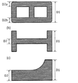
- the vibration damping component of this embodiment has an irregular cross-sectional shape. That is, the damping component has portions having different thicknesses in either the longitudinal direction and / or the thickness direction. Further, when the major axis of the cross section in the thickness direction is D1 and the minor axis is D2, it is preferable to have a deformed cross-sectional shape in which the difference between D1 and D2 is 0.5 mm or more.
- An example of a modified cross-sectional shape is shown in FIG.
- the modified cross-sectional shape of the present embodiment is, for example, a cross-sectional shape of a long part having a hollow cross section as shown in FIG. 8A, an H-shape as shown in FIG. 8B, and FIG.
- the minor diameter D2 has a thickness (D2a + D2b) excluding the hollow portion.
- the production method of the present embodiment is a heat source containing a metal powder containing Al: 4.0 to 12.0% in mass% and composed of the balance Fe and unavoidable impurities at a scanning speed of 700 mm / sec to 1700 mm / sec. Performs a modeling process to obtain a modeled body by melting and solidifying with.
- this alloy powder one produced by a commonly used powder production method can be used. For example, an atomizing method, a melt spinning method, or the like can be used.
- a generally known powder additive manufacturing method may be applied.
- the powder additive manufacturing method include a powder bed method and a direct metal deposition method.
- the heat source can also be appropriately selected from laser, electron beam, arc, plasma and the like.
- the powder bed method using a laser as a heat source is selected.
- the main feature of the manufacturing method of the present embodiment is that the scanning speed of the heat source is set to 700 mm / sec to 1700 mm / sec in the molding process of melting and solidifying the metal powder to obtain a modeled body.
- the average crystal grain size is about 100 to 300 ⁇ m, but in order to obtain coarse crystal grains exceeding 700 ⁇ m by annealing, it is necessary to leave an appropriate internal strain in the modeled body. There is. Internal strain is introduced by thermal stress due to rapid heating and quenching and transformation stress due to phase transformation, and recrystallization occurs using the magnitude as a driving force.
- the scanning speed of the heat source is set to 700 mm / sec or more in this embodiment.
- the preferred scanning speed is 800 mm / sec or higher.
- the scanning speed was set to 1700 mm / sec or less in this embodiment.
- a preferred scanning speed is 1600 mm / sec or less, and a more preferred scanning speed is 1500 mm / sec or less.
- the energy density of the heat source is 65 to 135 J / mm 3 while satisfying the scanning speed of the heat source described above.
- This energy density is calculated by P / (v ⁇ p ⁇ d) when the output of the scanning heat source is P, the scanning speed is v, the scanning interval is p, and the stacking thickness per layer is d.
- the modeled body of the present embodiment has a metal structure composed of an aggregate of quenching and solidifying structures.
- the microstructure has a columnar structure along the stacking direction. This columnar structure is mainly composed of the crystal orientations of (110) and (200), and the total ratio is preferably 90% or more. More preferably, it is 95% or more. As a result, it is considered that the microstructure after annealing becomes coarser. Further, it is preferable that the modeled body of this embodiment has many crystal grains having a GOS value (Grain Origination Spread) of 3 ° or more.
- the GOS value indicates a value obtained by averaging the orientation difference between an arbitrary measurement point and another measurement point in the grain within the same crystal grain.
- the number of crystal grains having a GOS value of 3 ° or more is preferably 100 grains / mm 2. More preferably, the number is 2 mm / mm.
- the molded body before annealing may be subjected to a hot isotropic pressure pressurization treatment of 50 MPa to 300 MPa at a temperature of 1100 ° C. to 1300 ° C.
- a hot isotropic pressure pressurization treatment of 50 MPa to 300 MPa at a temperature of 1100 ° C. to 1300 ° C.
- the obtained model body is annealed. This is because only crystal grains of about 300 ⁇ m can be obtained as they are, and it is necessary to coarsen the crystal grains by performing annealing and recrystallization. A state in which thermal stress remains due to rapid solidification is effective, but heating at 800 ° C. or higher is required for recrystallization. It is preferably 900 ° C. or higher. If the temperature exceeds 1200 ° C., the growth of crystal grains becomes slow and the heat treatment deformation becomes large, so the upper limit is set to 1200 ° C.
- a gas atomized powder having an Al content of 6.43%, 8.32%, and 10.40% in mass% and composed of the balance Fe and unavoidable impurities was prepared and classified into 10 to 53 ⁇ m.
- Gas atomization was carried out by melting at high frequency in vacuum, dropping the molten alloy from a nozzle with a diameter of 5 mm under the crucible, and spraying with high-pressure argon.
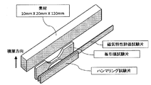
- a raw material powder a three-dimensional laminated molding machine (EOS-M290 manufactured by EOS), S45C as a base plate, and a powder bed method, high-speed melting and rapid solidification by laser irradiation, width 10 mm, length 120 mm, lamination height 20 mm
- a long-shaped model (Fig.
- the layered thickness per layer was 40 ⁇ m, and the irradiation direction was rotated by 67 ° for each layer.
- the beam diameter of the laser was about 0.1 mm, and the laser output was adjusted to 200 to 350 W.
- the modeling conditions are shown in Table 1.
- the types of powder are represented by A, B, and C, and the Al amounts correspond to 6.43%, 8.32%, and 10.40%, respectively.
- the annealing was carried out by heating and holding in a hydrogen stream for 30 minutes at the annealing temperature shown in Table 1, and then cooling at about 100 ° C./min.
- tissue observation and measurement of various characteristics were performed.
- the microstructure cross sections parallel to the thickness direction (lamination direction) were observed for two types, before annealing and after annealing.
- the cross section of the long shape shown in FIG. 1 was mirror-polished and then observed with an optical microscope (magnification: 200 times, measurement range: 10 mm 2 ).
- the obtained image was image-analyzed using image processing software ImageJ, and the defect ratio was determined as the area ratio of black defects in the microstructure after annealing.
- observe the sample after annealing with an optical microscope (magnification: 100 times) in the above cross section draw a line segment of 3 mm at right angles to the thickness direction, and count the intersections with the grain boundaries.
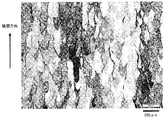
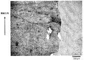
- FIGS. The microstructures of 2 before and after annealing are shown. Before annealing, columnar crystal grains grown in the stacking direction were observed, and the width was about 100 ⁇ m. After annealing at 1000 ° C., coarse recrystallized grains of about 1000 ⁇ m are obtained. Similarly, the other steels of the present invention were recrystallized by annealing to obtain recrystallization exceeding 700 ⁇ m.
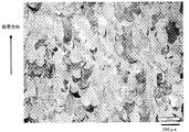
- Figures 4 and 5 show No. Twelve microstructures before and after annealing are shown. Equiaxial crystal grains were obtained before annealing, and almost no change was observed in the crystal grains after annealing. The tensile strength was higher than that of the example of the present invention due to the fine influence of the crystal grains, but the damping ratio was 0.1 or less in each case.
- the Fe—Al alloy damping component of the present invention and the manufacturing method thereof, it is possible to manufacture a three-dimensional component having a deformed cross-sectional shape, so that the Fe—Al alloy material is excellent in damping.
- the vibration damping characteristics are enhanced, and it can be applied to vehicle parts such as automobiles and parts such as processing machines that require higher quietness and vibration countermeasures.
Landscapes
- Chemical & Material Sciences (AREA)
- Engineering & Computer Science (AREA)
- Materials Engineering (AREA)
- Manufacturing & Machinery (AREA)
- Mechanical Engineering (AREA)
- Metallurgy (AREA)
- Organic Chemistry (AREA)
- Physics & Mathematics (AREA)
- Thermal Sciences (AREA)
- Crystallography & Structural Chemistry (AREA)
- Powder Metallurgy (AREA)
Abstract
凝固欠陥が少なく、欠陥が残っていたとしても制振特性が良好な、異形断面形状を有するFe-Al系制振部品とその製造方法を提供する。 質量%でAl:4.0~12.0%、残部Fe及び不可避的不純物でなり、平均結晶粒径が700μmを超えて2000μm以内の範囲内にあり、断面欠陥率が0.1%未満であり、異形断面形状を有する、Fe-Al系合金制振部品。また、質量%でAl:4.0~12.0%、残部Fe及び不可避的不純物でなる金属粉末を、走査速度を700mm/秒~1700mm/秒に設定した熱源で溶融凝固させ、造形体を得る造形工程と、前記造形体を800~1200℃の温度で焼鈍する焼鈍工程と、を含み、異形断面形状を有する制振部品を得る、Fe-Al系合金制振部品の製造方法とその製造方法。
Description
本発明は、Fe-Al系合金制振部品およびその製造方法に関するものである。
自動車などの車両の静粛性を向上させたり、切削機械などにおける仕上げ精度を向上させたりするための振動対策として、制振性に優れる金属材料の要求がある。前述の制振合金としては、例えば、Fe-Al合金、Fe-Cr-Al合金、Fe-Co-V合金があり、これらの合金は強磁性体型の制振合金として知られている。いずれも磁歪の大きな材料で、振動に伴う歪の大きさに応じた磁歪により材料内の磁壁が移動することで、振動の弾性エネルギーを吸収する。その他の制振合金としてMn-Cu合金があるが、これは熱弾性マルテンサイト変態における双晶変形を利用するもので、変態温度以上では制振効果がなくなる。強磁性体型は比較的に高い温度まで制振効果があり、中でもFe-Al合金は原料コストが安価であり、優れた制振性を有する制振合金として知られている。
このFe-Al合金は圧延など塑性加工を行って板として使用されることが多い。例えば、特許文献1(特開2014-80676)では厚さが1.4mm以下の冷間圧延材の製造工程が開示されており、特許文献2(特開2014-114468)では熱間加工による塑性加工と冷間圧延する冷間加工工程が開示されている。
これらの塑性加工材の平均結晶粒径については、結晶粒界が磁壁の移動の妨げとなるために、結晶粒が大きいほど磁歪も大きくなり内部摩擦を高める効果がある。特許文献3(特開2001-59139)では平均結晶粒径は300~700μmの範囲内に規定されている。結晶粒径が大きすぎると、冷間加工性が低下するのと、構造材料として必要な強度低下が懸念されるために上限が決められている。
これらの塑性加工材の平均結晶粒径については、結晶粒界が磁壁の移動の妨げとなるために、結晶粒が大きいほど磁歪も大きくなり内部摩擦を高める効果がある。特許文献3(特開2001-59139)では平均結晶粒径は300~700μmの範囲内に規定されている。結晶粒径が大きすぎると、冷間加工性が低下するのと、構造材料として必要な強度低下が懸念されるために上限が決められている。
ところで、上述したような制振部品の制振効果をより高めるためには、例えば部品内部に空間を設けるといったように、複雑な形状が必要になる傾向にある。このような複雑形状の部品を製造する方法として、金属材の粉末をレーザーなどによって局所的に溶融・凝固させて、構造物を任意の形状へ成型できる積層造形法が挙げられる。この積層造形法のような塑性加工を行わないプロセスは、設計の自由度が高く、制振材料と組み合わせることで、より大きな制振効果が期待される。
しかしながら上述したような積層造形法などの急速溶融急冷凝固プロセスを適用すると、部品内部に微小な欠陥や介在物が生成されやすく、振動減衰機構となる磁壁の移動を妨げて十分な制振効果が得られない可能性が考えられる。特許文献1~3には上記の課題について記載されておらず、検討の余地が残されている。
そこで本発明の目的は、凝固欠陥が少なく、微小欠陥が残っていても制振特性向上に有利なFe-Al系合金制振部品とその製造方法を提供することである。
そこで本発明の目的は、凝固欠陥が少なく、微小欠陥が残っていても制振特性向上に有利なFe-Al系合金制振部品とその製造方法を提供することである。
本発明者は凝固組織について鋭意検討した結果、制振特性が低下しない結晶粒径範囲と、この結晶粒径を得るための急速溶融急冷凝固プロセスについて見出し、本発明に到達した。
すなわち本発明の一態様は、質量%でAl:4.0~12.0%、残部Fe及び不可避的不純物でなり、平均結晶粒径が700μmを超えて2000μm以内の範囲内にあり、断面欠陥率が0.1%未満であり、異形断面形状を有する、Fe-Al系合金制振部品である。
すなわち本発明の一態様は、質量%でAl:4.0~12.0%、残部Fe及び不可避的不純物でなり、平均結晶粒径が700μmを超えて2000μm以内の範囲内にあり、断面欠陥率が0.1%未満であり、異形断面形状を有する、Fe-Al系合金制振部品である。
本発明の他の一態様は、質量%でAl:4.0~12.0%、残部Fe及び不可避的不純物でなる金属粉末を、走査速度を700mm/秒~1700mm/秒に設定した熱源で溶融凝固させ、造形体を得る造形工程と、前記造形体を800~1200℃の温度で焼鈍する焼鈍工程と、を含み、異形断面形状を有する制振部品を得る、Fe-Al系合金制振部品の製造方法である。
本発明によれば、凝固欠陥が少なく、微小欠陥が残っていても制振特性向上に有利なFe-Al系合金制振部品を提供することができる。
以下、本発明の実施形態について、具体的に説明する。
本発明のFe-Al系合金制振部品(以下、単に制振部品とも記載する。)は、質量%でAl:4.0~12.0%を含み、残部Fe及び不可避的不純物からなる。AlはFeに固溶し磁歪を増加させることで、制振性に寄与する。Alが増えると磁歪は大きくなり、10%前後で最大となる。一方、透磁率はAlが増えると低くなり、磁壁が動き難くなる。以上のことから、Alは4.0~12.0%とした。好ましい下限は6.0%であり、上限は10.0%である。
本発明のFe-Al系合金制振部品(以下、単に制振部品とも記載する。)は、質量%でAl:4.0~12.0%を含み、残部Fe及び不可避的不純物からなる。AlはFeに固溶し磁歪を増加させることで、制振性に寄与する。Alが増えると磁歪は大きくなり、10%前後で最大となる。一方、透磁率はAlが増えると低くなり、磁壁が動き難くなる。以上のことから、Alは4.0~12.0%とした。好ましい下限は6.0%であり、上限は10.0%である。
本実施形態の制振部品は、平均結晶粒径が700μmを超えて2000μm以内の範囲内であることが主要な特徴である。圧延などの塑性加工を含む従来の製造方法では、平均結晶粒径を300~500μm程度とすることで大きな制振特性が得られていた。しかし積層造形法により製造した部品では、微小な凝固欠陥や介在物が不可避に生成されるため、同じ結晶粒に制御しても微細な介在物、凝固欠陥により磁壁の移動が妨げられ、従来の塑性加工品よりも制振特性が小さいことが判明した。本実施形態の制振部品は平均結晶粒径を700μmを超えるように制御することで、上述した微小な凝固欠陥や介在物を有していても磁壁の移動が阻害されにくく、従来品と同等以上の制振特性を発揮することが可能である。一方で平均結晶粒径が大きくなりすぎると、制振部品の延性が低下する傾向にあるので、上限を2000μmとした。好ましい平均結晶粒径の下限は800μmであり、より好ましい平均結晶粒径の下限は900μmである。また、好ましい平均結晶粒径の上限は1800μmであり、より好ましい平均結晶粒径の上限は1600μmであり、さらに好ましい平均結晶粒径の上限は1400μmであり、特に好ましい平均結晶粒径の上限は1200μmである。なお、あまりにも欠陥が多すぎると、上記の平均結晶粒径を有していても十分な制振特性が得られないため、断面欠陥率が0.1%未満とする。なおこの断面欠陥率の測定は、例えば、部品の厚さ方向に平行な断面(長尺部品であれば、その横断面)を鏡面研磨した後、光学顕微鏡で観察し、得られた画像を解析することで測定することが可能である。
本実施形態の制振部品は、異形断面形状を有する。即ち、制振部品の長手方向と厚み方向の何れかまたは両方に、厚さが異なる部分を有する。さらには、厚さ方向の断面の長径をD1、短径をD2とした際に、D1とD2の差が0.5mm以上である異形断面形状を有することが好ましい。異形断面形状の例を図8に示す。本実施形態の異形断面形状とは、例えば、長尺部品の横断面で、図8(a)に示すような断面に中空を有する形状、図8(b)に示すようなH型、および図8(c)に示すような断面形状の肉厚が変化する形状である。なお図8(a)のような断面に中空を有する形状の場合、短径D2は、中空部分を除いた厚み(D2a+D2b)とする。
続いて本実施形態の製造方法について説明する。本実施形態の製造方法は、質量%でAl:4.0~12.0%を含み、残部Fe及び不可避的不純物からなる金属粉末を、走査速度を700mm/秒~1700mm/秒に設定した熱源で溶融凝固させ、造形体を得る造形工程を行う。この合金粉末は一般的に使用されている粉末製造法により製造されたものを用いることができる。例えば、アトマイズ法や、メルトスピニング法等を用いることができる。
本実施形態における、粉末を溶融凝固させる手段としては、一般的に知られている粉末積層造形法を適用すればよい。粉末積層造形法としては、例えば、パウダーベッド法、ダイレクトメタルデポジション法等が上げられる。熱源も、レーザー、電子ビーム、アーク、プラズマ等から適宜選択することができる。なお本実施形態では、レーザーを熱源としたパウダーベッド法を選択している。
本実施形態の製造方法における主要な特徴は、金属粉末を溶融凝固させ、造形体を得る造形工程において、熱源の走査速度を700mm/秒~1700mm/秒に設定することにある。造形工程後の造形体を観察すると、平均結晶粒径は100~300μm程度であるが、これを焼鈍で700μmを超える粗大結晶粒にするためには、造形体に適度な内部歪みを残存させる必要がある。内部歪みは急熱急冷による熱応力、相変態にともなう変態応力により導入され、その大きさを駆動力にして再結晶が発生する。走査速度が遅く、凝固がゆっくりと進行すると、内部に蓄積される歪みが小さくなり、焼鈍しても再結晶せずに、凝固時の結晶粒(100~300μm程度の等軸粒)がそのまま残る傾向にあるため、本実施形態では熱源の走査速度を700mm/秒以上とした。好ましい走査速度は800mm/秒以上である。一方で走査速度を速くして、凝固速度を大きくすると、内部歪みは大きくなるが、再結晶の核となる発生サイトが多くなり、再結晶粒は微細になる傾向にある。また、凝固速度が大きくなると、凝固欠陥も多くなり再結晶の成長が妨げられ、造形体の強度も低下する可能性があるため、本実施形態では走査速度を1700mm/秒以下とした。好ましい走査速度は1600mm/秒以下であり、より好ましい走査速度は1500mm/秒以下である。
また本実施形態の製造方法では、上述した熱源の走査速度を満たしつつ、熱源のエネルギー密度を65~135J/mm3にすることが好ましい。このエネルギー密度は、走査熱源の出力をP、走査速度をv、走査間隔をp、1層当たりの積層厚さをdとした時に、P/(v・p・d)で計算される。上述したエネルギー密度範囲内で金属粉末を溶融凝固させることで、安定して焼鈍後に粗大な結晶粒を得ることが可能である。
本実施形態の造形体は、急冷凝固組織の集合からなる金属組織を有している。そのミクロ組織は積層方向に沿った柱状組織を有している。この柱状組織は(110)(200)の結晶方位を主体としており、合わせて90%以上の比率であることが好ましい。より好ましくは95%以上である。これにより、焼鈍後のミクロ組織がより粗大になると考えられる。また本実施形態の造形体は、GOS値(Grain Orientation Spread)が3°以上の結晶粒が多いことが好ましい。このGOS値とは、同じ結晶粒内において、任意の測定点と粒内の他の測定点との測定点間の方位差を平均化した値を示す。例えば、上記の積層方向に沿った柱状組織(図1の場合、厚さ方向に平行な断面組織)において、GOS値が3°以上の結晶粒が100個/mm2であることが好ましく、150個/mm2であることがより好ましい。
本実施形態の製造方法では、焼鈍前の造形体に、1100℃~1300℃の温度で、50MPa~300MPaの熱間等方圧加圧処理を行ってもよい。これにより、内部の欠陥を減少させて制振部品の性能をさらに高める効果が期待できる。
本実施形態の製造方法では、得られた造形体に対して焼鈍を行う。これは造形体のままでは300μm程度の結晶粒しか得られないため、焼鈍を実施し再結晶させることで結晶粒を粗大化させる必要があるためである。急速凝固で熱応力が残存した状態が有効であるが、再結晶させるためには800℃以上の加熱が必要である。好ましくは900℃以上である。1200℃を超えると結晶粒の成長は緩やかとなり、熱処理変形が大きくなるので上限は1200℃とした。
以上、本発明の実施形態について詳述したが、本発明は、前記の実施形態に限定されるものではなく、特許請求の範囲に記載された本発明の精神を逸脱しない範囲で、種々の変更を行うことができるものである。例えば、焼鈍後の部品に対して形状精度を高めるために、切削等の加工工程を導入してもよい。
質量%でのAl量が6.43%、8.32%、10.40%で残部Fe及び不可避的不純物からなる成分のガスアトマイズ粉を作製し、10~53μmに分級した。ガスアトマイズは真空中で高周波溶解し、るつぼ下の直径5mmノズルから溶融した合金を落下させ、高圧アルゴンで噴霧することで実施した。これを原料粉末とし、3次元積層造形機(EOS社製、EOS-M290)で、S45Cをベースプレートとし、パウダーベット方式でレーザー照射による高速溶融急凝固で幅10mm、長さ120mm、積層高さ20mmの長尺形状の造形体(図1)を作製した。1層当たりの積層厚みは40μmで1層ごとに照射方向を67°づつ回転させた。レーザーのビーム径は0.1mm程度でレーザー出力を200~350Wで調整した。造形条件を表1に示す。粉末の種類はA,B、Cで表しており、それぞれAl量が6.43%、8.32%、10.40%に対応する。焼鈍は表1に示す焼鈍温度で水素気流中で30分間加熱保持した後に、100℃/分程度で冷却した。
続いて組織観察と各種特性の測定を行った。ミクロ組織は焼鈍前と焼鈍後の2種類について、厚み方向(積層方向)に平行な断面を観察した。具体的には図1の長尺形状における横断面を鏡面研磨した後、光学顕微鏡(倍率:200倍、測定範囲:10mm2)で観察した。得られた画像は画像処理ソフトウェアImageJを用いて画像解析し、欠陥率は焼鈍後のミクロ組織の黒色欠陥の面積率を求めた。
結晶粒径は、焼鈍後の試料を上記の横断面において光学顕微鏡(倍率:100倍)で観察し、厚み方向に対して直角に3mmの線分を引き、結晶粒界との交点をカウントして算出した。この時線分は同じ結晶粒と交わらないように任意に10本引き、平均値を平均結晶粒径とした。表1に合わせて結果を示す。
各種特性は造形体から、図1に示すような方向に、減衰比測定用のハンマリング用の短冊試験片(厚さ1.5mm、幅10mm、長さ60mm)、磁気特性評価用の薄板試験片(厚さ0.6mm、幅8mm、長さ120mm)、引張試験片(平行部2.6mm角、長さ11mm)を採取した。採取した試料はそれぞれ、表1に示す焼鈍温度で焼鈍を行った後に評価を行った。
ハンマリング試験は片側25mmをバイスで固定し、突き出し長さを35mmとし、平面の先端に加速度センサーを付着させて、幅側面をインパルスハンマーを使って約50Nの力で叩き減衰特性(共振周波数、減衰比)を測定した。
透磁率は単板磁気特性試験(直流)に準じ、有効磁路長を約90mmとし、1次コイルにより4000A/mの磁場を印加し、励磁された磁束を2次コイルで測定して透磁率を測定した。
引張試験はJIS-Z-2241(2011)に従って室温で行い、引張強さ、伸びを測定した。各種特性の測定結果を表2に結果を示す。
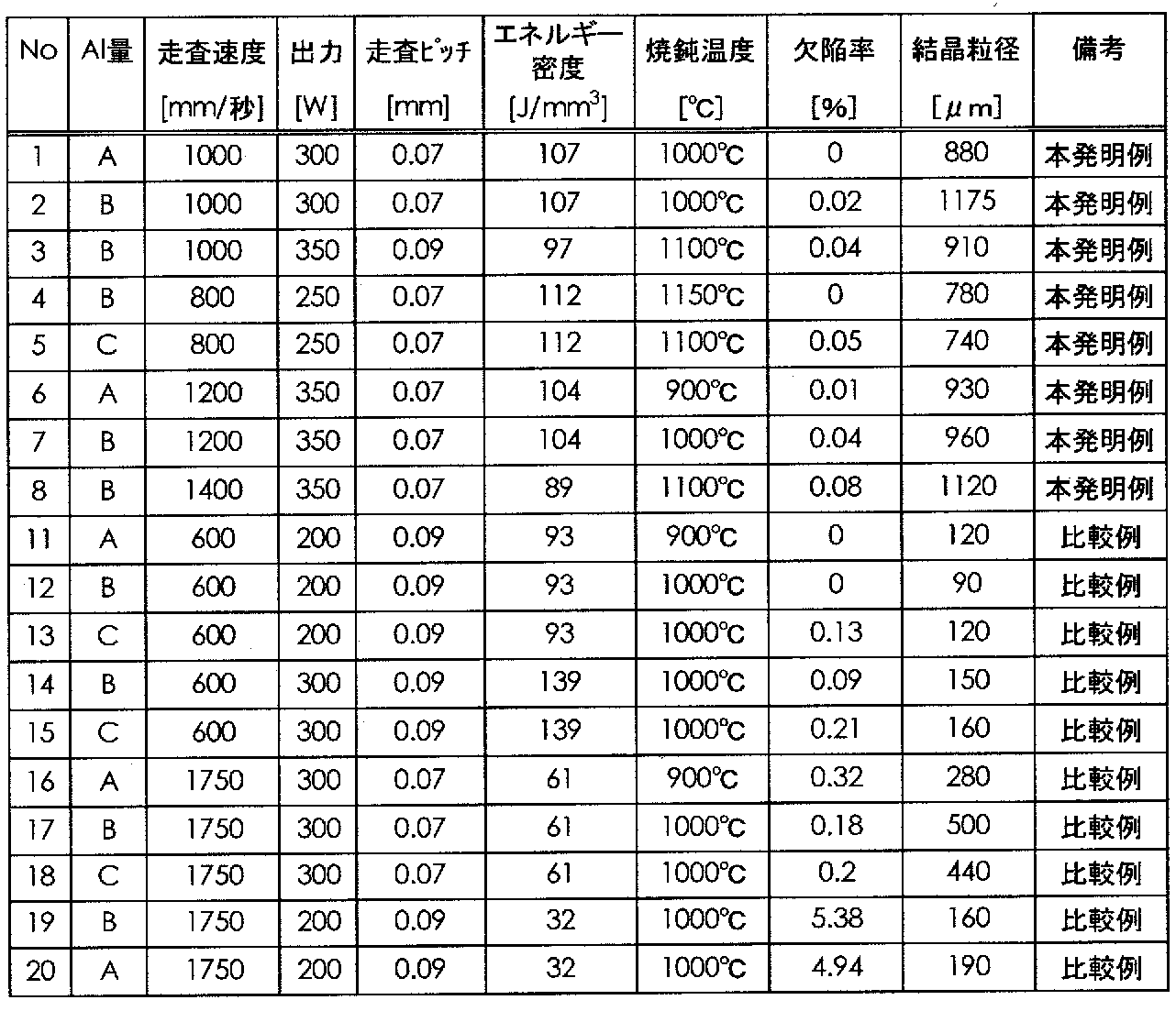
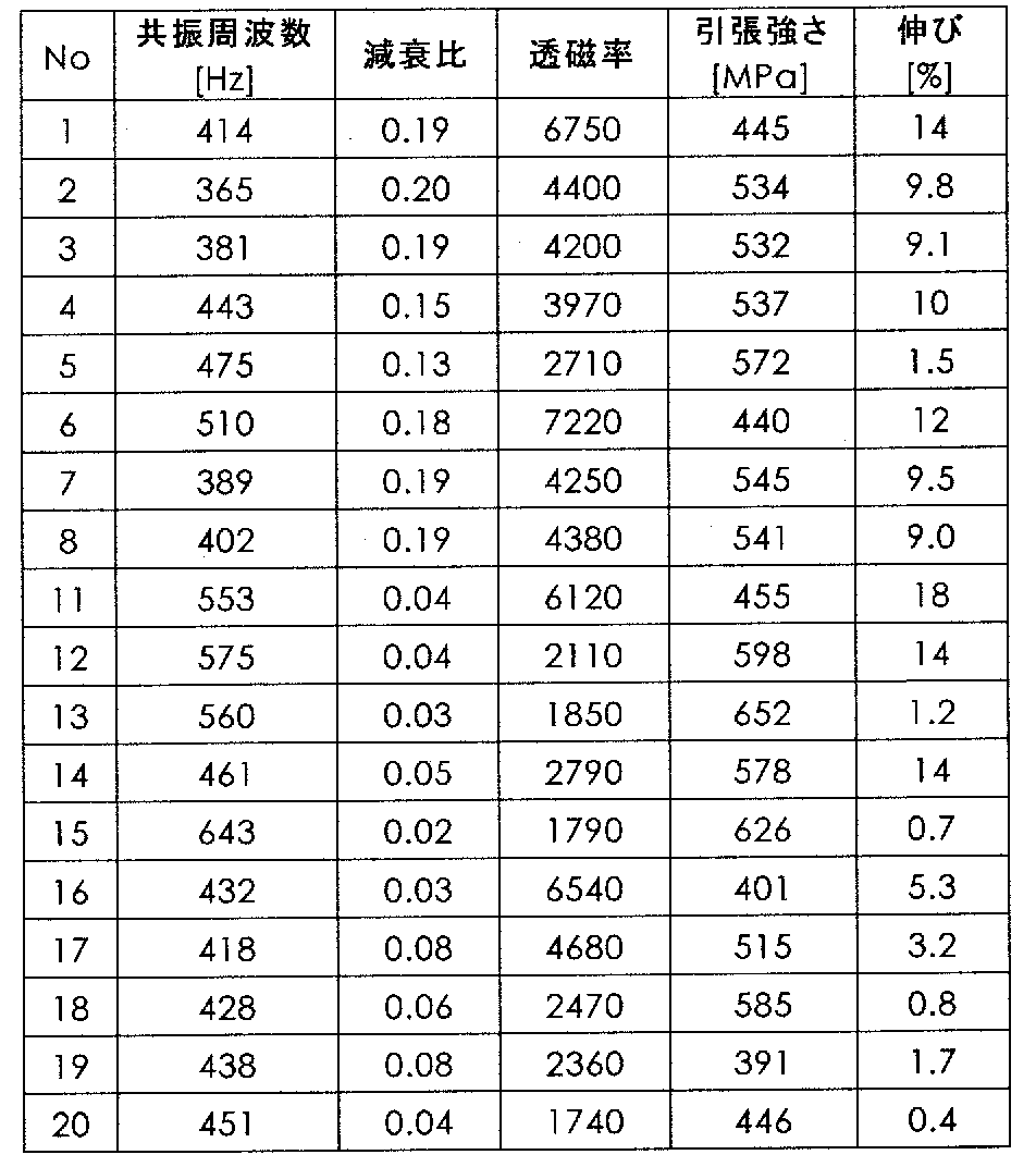
表1の結果より、走査速度が800~1700mm/秒の範囲内である本発明例のNo.1~8は、焼鈍後の平均結晶粒径は700μmを超えており、欠陥率も0.1%未満であった。ハンマリング試験では共振周波数300~500Hzの範囲で減衰比は0.1以上となった。従来品である6~10%Alの圧延材の焼鈍後の減衰比が、同一の試験方法で、0.13~0.2の範囲であるので、ほぼ同等の減衰特性が得られていることが確認できた。特に平均結晶粒径が800μm以上であるNo.1~3、No.6~8は、減衰比が0.18~0.19と、本発明例の中でも大きい水準であることを確認した。
代表例として、図2、3にそれぞれNo.2の焼鈍前と焼鈍後のミクロ組織を示す。焼鈍前は積層方向に成長した柱状結晶粒が観察され、幅は約100μm程度である。1000℃の焼鈍後には約1000μm程度の粗大な再結晶粒が得られている。その他の本発明鋼も同様に、焼鈍で再結晶し700μmを超える再結晶が得られた。
比較例であるNo.11~15は走査速度が600mm/秒と本発明例よりも遅い場合であり、焼鈍後にほとんど再結晶が起こらず、平均結晶粒径は100~150μm程度である。図4、5にそれぞれNo.12の焼鈍前と焼鈍後のミクロ組織を示す。焼鈍前では等軸の結晶粒が得られており、焼鈍後の結晶粒もほとんど変化は見られない。引張強度は結晶粒が微細な影響もあり、本発明例よりも高めの値であるが、減衰比はいずれも0.1以下となった。
比較例であるNo.16~20は走査速度が1750mm/秒と速い場合で、焼鈍前では欠陥が多く、いずれも欠陥率は0.1を超えており、焼鈍後に再結晶するものの結晶粒径は小さいことが確認された。図6.7にそれぞれNo.19の焼鈍前と焼鈍後のミクロ組織を示す。焼鈍前では欠陥が多く分散した組織となっており、焼鈍後は再結晶はしているが、結晶粒径は小さい。そのため比較例の制振部品は強度、延性が低く、また耐食性も低下する可能性が高い。
本発明のFe-Al系合金制振部品及びその製造方法によれば、異形断面形状を有する3次元形状の部品を製造することが可能なために、Fe-Al系合金材料の優れた制振特性と形状設計を組み合わせることにより、制振特性が高まり、より高い静粛性、振動対策が必要な、自動車などの車両部品、加工機械などの部品への適用が可能となる。
Claims (2)
- 質量%でAl:4.0~12.0%、残部Fe及び不可避的不純物でなり、
平均結晶粒径が700μmを超えて2000μm以内の範囲内にあり、断面欠陥率が0.1%未満であり、異形断面形状を有する、Fe-Al系合金制振部品。 - 質量%でAl:4.0~12.0%、残部Fe及び不可避的不純物でなる金属粉末を、走査速度を700mm/秒~1700mm/秒に設定した熱源で溶融凝固させ、造形体を得る造形工程と、
前記造形体を800~1200℃の温度で焼鈍する焼鈍工程と、
を含み、異形断面形状を有する制振部品を得る、Fe-Al系合金制振部品の製造方法。
Priority Applications (4)
| Application Number | Priority Date | Filing Date | Title |
|---|---|---|---|
| DE112020002548.9T DE112020002548T5 (de) | 2019-05-31 | 2020-05-22 | SCHWINGUNGSDÄMPFENDES BAUTEIL AUS EINER LEGIERUNG AUF FE-Al-BASIS UND VERFAHREN ZUR HERSTELLUNG DAVON |
| US17/613,474 US11913097B2 (en) | 2019-05-31 | 2020-05-22 | Fe—Al-based alloy vibration-damping component and method for manufacturing same |
| CN202080038646.2A CN113874140B (zh) | 2019-05-31 | 2020-05-22 | Fe-Al系合金减振零件及其制造方法 |
| JP2021522330A JP7494847B2 (ja) | 2019-05-31 | 2020-05-22 | Fe-Al系合金制振部品およびその製造方法 |
Applications Claiming Priority (2)
| Application Number | Priority Date | Filing Date | Title |
|---|---|---|---|
| JP2019102725 | 2019-05-31 | ||
| JP2019-102725 | 2019-05-31 |
Publications (1)
| Publication Number | Publication Date |
|---|---|
| WO2020241530A1 true WO2020241530A1 (ja) | 2020-12-03 |
Family
ID=73553482
Family Applications (1)
| Application Number | Title | Priority Date | Filing Date |
|---|---|---|---|
| PCT/JP2020/020422 Ceased WO2020241530A1 (ja) | 2019-05-31 | 2020-05-22 | Fe-Al系合金制振部品およびその製造方法 |
Country Status (5)
| Country | Link |
|---|---|
| US (1) | US11913097B2 (ja) |
| JP (1) | JP7494847B2 (ja) |
| CN (1) | CN113874140B (ja) |
| DE (1) | DE112020002548T5 (ja) |
| WO (1) | WO2020241530A1 (ja) |
Cited By (3)
| Publication number | Priority date | Publication date | Assignee | Title |
|---|---|---|---|---|
| JPWO2022219981A1 (ja) * | 2021-04-13 | 2022-10-20 | ||
| JP2023045935A (ja) * | 2021-09-22 | 2023-04-03 | 株式会社プロテリアル | Fe-Al系合金、Fe-Al系合金部材、Fe-Al系合金粉末およびFe-Al系合金の製造方法 |
| JP2024503643A (ja) * | 2021-01-07 | 2024-01-26 | グラインドソニック・ベスローテン・フエンノートシャップ | 改良された付加製造監視方法およびシステム |
Citations (3)
| Publication number | Priority date | Publication date | Assignee | Title |
|---|---|---|---|---|
| JPH08120394A (ja) * | 1994-10-17 | 1996-05-14 | Sumitomo Metal Ind Ltd | 高剛性材料の製造方法 |
| JP2001059139A (ja) * | 1999-08-18 | 2001-03-06 | Osaka City | 制振合金材料、その製造方法およびそれを用いた工具部材 |
| WO2013150972A1 (ja) * | 2012-04-03 | 2013-10-10 | 日立金属株式会社 | Fe-Al系合金の製造方法 |
Family Cites Families (6)
| Publication number | Priority date | Publication date | Assignee | Title |
|---|---|---|---|---|
| EP1847624A4 (en) | 2005-02-10 | 2008-05-28 | Yoshihira Okanda | NEW FE-AL ALLOYING AND MANUFACTURING METHOD THEREFOR |
| CN103691741A (zh) | 2012-09-27 | 2014-04-02 | 日立金属株式会社 | Fe-Al系合金带钢的制造方法 |
| JP2014080676A (ja) | 2012-09-27 | 2014-05-08 | Hitachi Metals Ltd | Fe−Al系合金帯鋼の製造方法 |
| JP6142411B2 (ja) | 2012-12-07 | 2017-06-07 | 株式会社アルフェコ | Fe−Al合金の製造方法 |
| JP6370276B2 (ja) | 2015-08-17 | 2018-08-08 | 日新製鋼株式会社 | 高Al含有制振性フェライト系ステンレス鋼材および製造方法 |
| US11376692B2 (en) * | 2018-10-04 | 2022-07-05 | Abb Schweiz Ag | Articles of manufacture and methods for additive manufacturing of articles having desired magnetic anisotropy |
-
2020
- 2020-05-22 JP JP2021522330A patent/JP7494847B2/ja active Active
- 2020-05-22 US US17/613,474 patent/US11913097B2/en active Active
- 2020-05-22 DE DE112020002548.9T patent/DE112020002548T5/de active Pending
- 2020-05-22 CN CN202080038646.2A patent/CN113874140B/zh active Active
- 2020-05-22 WO PCT/JP2020/020422 patent/WO2020241530A1/ja not_active Ceased
Patent Citations (3)
| Publication number | Priority date | Publication date | Assignee | Title |
|---|---|---|---|---|
| JPH08120394A (ja) * | 1994-10-17 | 1996-05-14 | Sumitomo Metal Ind Ltd | 高剛性材料の製造方法 |
| JP2001059139A (ja) * | 1999-08-18 | 2001-03-06 | Osaka City | 制振合金材料、その製造方法およびそれを用いた工具部材 |
| WO2013150972A1 (ja) * | 2012-04-03 | 2013-10-10 | 日立金属株式会社 | Fe-Al系合金の製造方法 |
Cited By (7)
| Publication number | Priority date | Publication date | Assignee | Title |
|---|---|---|---|---|
| JP2024503643A (ja) * | 2021-01-07 | 2024-01-26 | グラインドソニック・ベスローテン・フエンノートシャップ | 改良された付加製造監視方法およびシステム |
| JP7807096B2 (ja) | 2021-01-07 | 2026-01-27 | グラインドソニック・ベスローテン・フエンノートシャップ | 改良された付加製造監視方法およびシステム |
| JPWO2022219981A1 (ja) * | 2021-04-13 | 2022-10-20 | ||
| WO2022219981A1 (ja) * | 2021-04-13 | 2022-10-20 | 国立大学法人東北大学 | 磁歪材料の製造方法、磁歪材料およびエネルギー変換部材の製造方法 |
| CN117157160A (zh) * | 2021-04-13 | 2023-12-01 | 国立大学法人东北大学 | 磁致伸缩材料的制造方法、磁致伸缩材料及能量转换构件的制造方法 |
| JP2023045935A (ja) * | 2021-09-22 | 2023-04-03 | 株式会社プロテリアル | Fe-Al系合金、Fe-Al系合金部材、Fe-Al系合金粉末およびFe-Al系合金の製造方法 |
| JP7775607B2 (ja) | 2021-09-22 | 2025-11-26 | 株式会社プロテリアル | Fe-Al系合金、Fe-Al系合金部材およびFe-Al系合金の製造方法。 |
Also Published As
| Publication number | Publication date |
|---|---|
| CN113874140B (zh) | 2023-08-29 |
| US20220220594A1 (en) | 2022-07-14 |
| US11913097B2 (en) | 2024-02-27 |
| DE112020002548T5 (de) | 2022-02-17 |
| JP7494847B2 (ja) | 2024-06-04 |
| JPWO2020241530A1 (ja) | 2020-12-03 |
| CN113874140A (zh) | 2021-12-31 |
Similar Documents
| Publication | Publication Date | Title |
|---|---|---|
| US6689234B2 (en) | Method of producing metallic materials | |
| JP2019210552A (ja) | 先進的高強度金属合金の生産のための再結晶、微細化、及び強化機構 | |
| WO2013005714A1 (ja) | 冷延鋼板の製造方法 | |
| JP5825205B2 (ja) | 冷延鋼板の製造方法 | |
| JP2013023721A (ja) | 温間成形用高強度鋼板およびその製造方法 | |
| JP7494847B2 (ja) | Fe-Al系合金制振部品およびその製造方法 | |
| KR102195866B1 (ko) | 고항복강도 강판 | |
| WO2021149676A1 (ja) | 鋼板およびその製造方法 | |
| WO2017030063A1 (ja) | 制振性フェライト系ステンレス鋼材および製造方法 | |
| JP7741445B2 (ja) | チタン合金材、チタン合金線材、チタン合金粉末およびチタン合金材の製造方法 | |
| JP5185613B2 (ja) | 新規Fe−Al合金、及びその製造方法 | |
| JP6398210B2 (ja) | 冷延鋼板の製造方法 | |
| JP7388337B2 (ja) | 制振合金およびその製造方法 | |
| WO2011152328A1 (ja) | 高強度熱延鋼板およびその製造方法 | |
| JP5648596B2 (ja) | 冷延鋼板の製造方法 | |
| US12110579B2 (en) | Method of producing a CoFe alloy strip | |
| JP7397381B2 (ja) | ホットスタンプ用鋼板およびホットスタンプ成形体 | |
| JP7775607B2 (ja) | Fe-Al系合金、Fe-Al系合金部材およびFe-Al系合金の製造方法。 | |
| JP2007321208A (ja) | 高強度鋼の製造方法 | |
| JP6142411B2 (ja) | Fe−Al合金の製造方法 | |
| JP5659930B2 (ja) | 鉄合金製制振材の製造方法と鉄合金製制振材 | |
| JP7372226B2 (ja) | 制振合金およびその製造方法 | |
| JP7397380B2 (ja) | ホットスタンプ用鋼板およびホットスタンプ成形体 | |
| JP5708319B2 (ja) | 冷延鋼板 | |
| CA3030322C (en) | High yield strength steel |
Legal Events
| Date | Code | Title | Description |
|---|---|---|---|
| 121 | Ep: the epo has been informed by wipo that ep was designated in this application |
Ref document number: 20814946 Country of ref document: EP Kind code of ref document: A1 |
|
| ENP | Entry into the national phase |
Ref document number: 2021522330 Country of ref document: JP Kind code of ref document: A |
|
| 122 | Ep: pct application non-entry in european phase |
Ref document number: 20814946 Country of ref document: EP Kind code of ref document: A1 |