WO2020241235A1 - Electronic device, electronic device control method, and program - Google Patents
Electronic device, electronic device control method, and program Download PDFInfo
- Publication number
- WO2020241235A1 WO2020241235A1 PCT/JP2020/018947 JP2020018947W WO2020241235A1 WO 2020241235 A1 WO2020241235 A1 WO 2020241235A1 JP 2020018947 W JP2020018947 W JP 2020018947W WO 2020241235 A1 WO2020241235 A1 WO 2020241235A1
- Authority
- WO
- WIPO (PCT)
- Prior art keywords
- control unit
- electronic device
- moving body
- signal
- wave
- Prior art date
Links
Images
Classifications
-
- G—PHYSICS
- G08—SIGNALLING
- G08G—TRAFFIC CONTROL SYSTEMS
- G08G1/00—Traffic control systems for road vehicles
- G08G1/16—Anti-collision systems
- G08G1/166—Anti-collision systems for active traffic, e.g. moving vehicles, pedestrians, bikes
-
- G—PHYSICS
- G08—SIGNALLING
- G08G—TRAFFIC CONTROL SYSTEMS
- G08G1/00—Traffic control systems for road vehicles
- G08G1/16—Anti-collision systems
-
- G—PHYSICS
- G01—MEASURING; TESTING
- G01S—RADIO DIRECTION-FINDING; RADIO NAVIGATION; DETERMINING DISTANCE OR VELOCITY BY USE OF RADIO WAVES; LOCATING OR PRESENCE-DETECTING BY USE OF THE REFLECTION OR RERADIATION OF RADIO WAVES; ANALOGOUS ARRANGEMENTS USING OTHER WAVES
- G01S13/00—Systems using the reflection or reradiation of radio waves, e.g. radar systems; Analogous systems using reflection or reradiation of waves whose nature or wavelength is irrelevant or unspecified
- G01S13/02—Systems using reflection of radio waves, e.g. primary radar systems; Analogous systems
- G01S13/06—Systems determining position data of a target
- G01S13/08—Systems for measuring distance only
- G01S13/32—Systems for measuring distance only using transmission of continuous waves, whether amplitude-, frequency-, or phase-modulated, or unmodulated
- G01S13/34—Systems for measuring distance only using transmission of continuous waves, whether amplitude-, frequency-, or phase-modulated, or unmodulated using transmission of continuous, frequency-modulated waves while heterodyning the received signal, or a signal derived therefrom, with a locally-generated signal related to the contemporaneously transmitted signal
- G01S13/343—Systems for measuring distance only using transmission of continuous waves, whether amplitude-, frequency-, or phase-modulated, or unmodulated using transmission of continuous, frequency-modulated waves while heterodyning the received signal, or a signal derived therefrom, with a locally-generated signal related to the contemporaneously transmitted signal using sawtooth modulation
-
- G—PHYSICS
- G01—MEASURING; TESTING
- G01S—RADIO DIRECTION-FINDING; RADIO NAVIGATION; DETERMINING DISTANCE OR VELOCITY BY USE OF RADIO WAVES; LOCATING OR PRESENCE-DETECTING BY USE OF THE REFLECTION OR RERADIATION OF RADIO WAVES; ANALOGOUS ARRANGEMENTS USING OTHER WAVES
- G01S13/00—Systems using the reflection or reradiation of radio waves, e.g. radar systems; Analogous systems using reflection or reradiation of waves whose nature or wavelength is irrelevant or unspecified
- G01S13/02—Systems using reflection of radio waves, e.g. primary radar systems; Analogous systems
- G01S13/50—Systems of measurement based on relative movement of target
- G01S13/52—Discriminating between fixed and moving objects or between objects moving at different speeds
-
- G—PHYSICS
- G01—MEASURING; TESTING
- G01S—RADIO DIRECTION-FINDING; RADIO NAVIGATION; DETERMINING DISTANCE OR VELOCITY BY USE OF RADIO WAVES; LOCATING OR PRESENCE-DETECTING BY USE OF THE REFLECTION OR RERADIATION OF RADIO WAVES; ANALOGOUS ARRANGEMENTS USING OTHER WAVES
- G01S13/00—Systems using the reflection or reradiation of radio waves, e.g. radar systems; Analogous systems using reflection or reradiation of waves whose nature or wavelength is irrelevant or unspecified
- G01S13/02—Systems using reflection of radio waves, e.g. primary radar systems; Analogous systems
- G01S13/50—Systems of measurement based on relative movement of target
- G01S13/58—Velocity or trajectory determination systems; Sense-of-movement determination systems
- G01S13/583—Velocity or trajectory determination systems; Sense-of-movement determination systems using transmission of continuous unmodulated waves, amplitude-, frequency-, or phase-modulated waves and based upon the Doppler effect resulting from movement of targets
- G01S13/584—Velocity or trajectory determination systems; Sense-of-movement determination systems using transmission of continuous unmodulated waves, amplitude-, frequency-, or phase-modulated waves and based upon the Doppler effect resulting from movement of targets adapted for simultaneous range and velocity measurements
-
- G—PHYSICS
- G01—MEASURING; TESTING
- G01S—RADIO DIRECTION-FINDING; RADIO NAVIGATION; DETERMINING DISTANCE OR VELOCITY BY USE OF RADIO WAVES; LOCATING OR PRESENCE-DETECTING BY USE OF THE REFLECTION OR RERADIATION OF RADIO WAVES; ANALOGOUS ARRANGEMENTS USING OTHER WAVES
- G01S13/00—Systems using the reflection or reradiation of radio waves, e.g. radar systems; Analogous systems using reflection or reradiation of waves whose nature or wavelength is irrelevant or unspecified
- G01S13/88—Radar or analogous systems specially adapted for specific applications
- G01S13/93—Radar or analogous systems specially adapted for specific applications for anti-collision purposes
- G01S13/931—Radar or analogous systems specially adapted for specific applications for anti-collision purposes of land vehicles
Definitions
- This disclosure relates to electronic devices, electronic device control methods, and programs.
- radar Radio Detecting and Langing
- RADAR Radio Detecting and Langing
- Techniques have been studied in various ways. The importance of technology for measuring such distances will increase in the future with the development of technology that assists the driver's driving and technology related to autonomous driving that automates part or all of the driving. is expected.
- Patent Document 1 irradiates a target object with a transmission signal that has undergone linear FM modulation at a specific cycle, detects a beat signal based on the difference from the reception signal from the target object, and analyzes the frequency and speed of this signal. It discloses an FM-CW radar device that performs measurement.
- the electronic device is an electronic device mounted on a mobile body, and includes a transmitting antenna for transmitting a transmitted wave, a receiving antenna for receiving the reflected wave reflected by the transmitted wave, a control unit, and the like.
- the control unit detects an object that reflects the transmitted wave based on the transmitted signal transmitted as the transmitted wave and the received signal received as the reflected wave.
- the control unit estimates the time until the object reaches the moving body based on the transmission signal and the reception signal, and the moving body control unit that controls the moving body detects the object at the time. Notify accordingly.
- the method for controlling an electronic device is a method for controlling an electronic device mounted on a mobile body, and includes the following steps. (1) Step of transmitting the transmitted wave from the transmitting antenna (2) Step of receiving the reflected wave reflected by the transmitted wave from the receiving antenna (3) The transmitted signal transmitted as the transmitted wave and received as the reflected wave Step of detecting an object reflecting the transmitted wave based on the received signal (4) Step of estimating the time required for the object to reach the moving body based on the transmitted signal and the received signal (5) ) A step of notifying the moving body control unit that controls the moving body of the detection of the object according to the time.
- the program causes an electronic device mounted on the mobile body to execute the above steps (1) to (5).
- An object of the present disclosure is to provide electronic devices, control methods and programs for electronic devices that can improve the safety of mobile objects. According to one embodiment, it is possible to provide an electronic device, a control method for the electronic device, and a program that can improve the safety of the moving body.
- the electronic device can detect a predetermined object existing around the moving body by being mounted on a vehicle (moving body) such as an automobile or the like. Therefore, the electronic device according to the embodiment can transmit a transmitted wave around the mobile body from a transmitting antenna installed on the mobile body. Further, the electronic device according to the embodiment can receive the reflected wave in which the transmitted wave is reflected from the receiving antenna installed in the mobile body. At least one of the transmitting antenna and the receiving antenna may be provided in, for example, a radar sensor installed in a moving body.
- the electronic device according to one embodiment is mounted on an automobile such as a passenger car.
- the electronic device according to one embodiment may be mounted on various moving objects such as agricultural work devices such as buses, trucks, motorcycles, bicycles, ships, aircrafts, and tractors, snowplows, cleaning vehicles, police cars, ambulances, and drones. ..
- the electronic device according to the embodiment is not necessarily mounted on a moving body that moves by its own power.
- the moving body on which the electronic device according to the embodiment is mounted may be a trailer portion towed by a tractor.
- the electronic device can measure the distance between the sensor and the object in a situation where at least one of the sensor and a predetermined object can move. Further, the electronic device according to the embodiment can measure the distance between the sensor and the object even if both the sensor and the object are stationary.
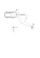
- FIG. 1 is a diagram illustrating a usage mode of the electronic device according to the embodiment.
- FIG. 1 shows an example in which a sensor including a transmitting antenna and a receiving antenna according to an embodiment is installed on a moving body.
- the mobile body 100 shown in FIG. 1 is provided with a sensor 5 including a transmitting antenna and a receiving antenna according to the embodiment. Further, it is assumed that the mobile body 100 shown in FIG. 1 is equipped (for example, built-in) with the electronic device 1 according to the embodiment. The specific configuration of the electronic device 1 will be described later.
- the sensor 5 may include, for example, at least one of a transmitting antenna and a receiving antenna. Further, the sensor 5 may appropriately include at least one of other functional units such as at least a part of the control unit 10 (FIG. 2) included in the electronic device 1.
- the moving body 100 shown in FIG. 1 may be an automobile vehicle such as a passenger car, but may be any type of moving body. In FIG. 1, the moving body 100 may, for example, move (run or slow) in the positive direction (traveling direction) of the Y axis shown in the figure, move in another direction, or move. It may be stationary without.
- a sensor 5 provided with a transmitting antenna is installed in the moving body 100.
- only one sensor 5 including a transmitting antenna and a receiving antenna is installed in front of the moving body 100.
- the position where the sensor 5 is installed on the moving body 100 is not limited to the position shown in FIG. 1, and may be another position as appropriate.
- the sensor 5 as shown in FIG. 1 may be installed on the left side, the right side, and / or the rear of the moving body 100.
- the number of such sensors 5 may be any one or more depending on various conditions (or requirements) such as the measurement range and / or accuracy of the moving body 100.
- the sensor 5 may be installed inside the moving body 100.
- the inside of the moving body 100 may be, for example, a space in a bumper, a space in a body, a space in a headlight, a space in a driving space, or the like.
- the sensor 5 transmits an electromagnetic wave as a transmission wave from the transmission antenna. For example, when a predetermined object (for example, the object 200 shown in FIG. 1) exists around the moving body 100, at least a part of the transmitted wave transmitted from the sensor 5 is reflected by the object to become a reflected wave. Then, by receiving such a reflected wave by, for example, the receiving antenna of the sensor 5, the electronic device 1 mounted on the mobile body 100 can detect the object.
- a predetermined object for example, the object 200 shown in FIG. 1
- the electronic device 1 mounted on the mobile body 100 can detect the object.
- the sensor 5 provided with a transmitting antenna may typically be a radar (RADAR (Radio Detecting and Ringing)) sensor that transmits and receives radio waves.
- RADAR Radio Detecting and Ringing
- the sensor 5 is not limited to the radar sensor.
- the sensor 5 according to one embodiment may be, for example, a sensor based on the technology of LIDAR (Light Detection and Ringing, Laser Imaging Detection and Ringing) using light waves.
- LIDAR Light Detection and Ringing, Laser Imaging Detection and Ringing
- a sensor such as these can be configured to include, for example, a patch antenna. Since technologies such as RADAR and LIDAR are already known, detailed description may be simplified or omitted as appropriate.
- the electronic device 1 mounted on the mobile body 100 shown in FIG. 1 receives the reflected wave of the transmitted wave transmitted from the transmitting antenna of the sensor 5 from the receiving antenna. In this way, the electronic device 1 can detect a predetermined object 200 existing within a predetermined distance from the moving body 100. For example, as shown in FIG. 1, the electronic device 1 can measure the distance L between the moving body 100, which is the own vehicle, and the predetermined object 200. The electronic device 1 can also measure the relative speed between the moving body 100, which is its own vehicle, and the predetermined object 200. Further, the electronic device 1 can also measure the direction (arrival angle ⁇ ) at which the reflected wave from the predetermined object 200 reaches the moving body 100 which is the own vehicle.
- the object 200 is, for example, at least one of an oncoming vehicle traveling in a lane adjacent to the moving body 100, a vehicle running in parallel with the moving body 100, and a vehicle before and after traveling in the same lane as the moving body 100.
- the object 200 is a moving object such as a motorcycle, a bicycle, a stroller, a pedestrian or other human being, an animal, an insect or other life form, a guardrail, a median strip, a road sign, a step on a sidewalk, a wall, a manhole, or an obstacle. It may be any object that exists around the body 100. Further, the object 200 may be moving or may be stationary. For example, the object 200 may be an automobile parked or stopped around the moving body 100.
- the ratio between the size of the sensor 5 and the size of the moving body 100 does not necessarily indicate the actual ratio.
- the sensor 5 is shown in a state of being installed outside the moving body 100.
- the sensor 5 may be installed at various positions on the moving body 100.
- the sensor 5 may be installed inside the bumper of the moving body 100 so as not to appear in the appearance of the moving body 100.
- the transmitting antenna of the sensor 5 will be described as transmitting radio waves in a frequency band such as millimeter waves (30 GHz or more) or quasi-millimeter waves (for example, around 20 GHz to 30 GHz).
- the transmitting antenna of the sensor 5 may transmit radio waves having a frequency bandwidth of 4 GHz, such as 77 GHz to 81 GHz.
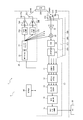
- FIG. 2 is a functional block diagram schematically showing a configuration example of the electronic device 1 according to the embodiment.
- FIG. 2 is a functional block diagram schematically showing a configuration example of the electronic device 1 according to the embodiment.
- an example of the configuration of the electronic device 1 according to the embodiment will be described.
- FMCW radar Frequency Modified Continuous Wave radar
- the FMCW radar sweeps the frequency of the radio wave to be transmitted to generate a transmission signal. Therefore, in a millimeter-wave FMCW radar that uses radio waves in the frequency band of 79 GHz, for example, the frequency of the radio waves used has a frequency bandwidth of 4 GHz, for example, 77 GHz to 81 GHz.
- Radars in the 79 GHz frequency band are characterized by a wider usable frequency bandwidth than other millimeter-wave / quasi-millimeter-wave radars, such as the 24 GHz, 60 GHz, and 76 GHz frequency bands.
- millimeter-wave / quasi-millimeter-wave radars such as the 24 GHz, 60 GHz, and 76 GHz frequency bands.
- the electronic device 1 according to the embodiment is composed of a sensor 5 and an ECU (Electronic Control Unit) 50.
- the ECU 50 controls various operations of the moving body 100.
- the ECU 50 may be a mobile body control unit that controls the mobile body 100. That is, the ECU 50 may be a specific example of the mobile control unit according to the embodiment.
- the ECU 50 is also referred to as a moving body control unit 50.
- the ECU 50 may be composed of at least one or more ECUs.
- the electronic device 1 according to the embodiment includes a control unit 10. Further, the electronic device 1 according to the embodiment may appropriately include other functional units such as at least one of the transmission unit 20, the reception units 30A to 30D, and the storage unit 40. As shown in FIG.
- the electronic device 1 may include a plurality of receiving units, such as the receiving units 30A to 30D.
- the receiving unit 30A, the receiving unit 30B, the receiving unit 30C, and the receiving unit 30D are simply referred to as "reception unit 30".
- the control unit 10 may include a distance FFT processing unit 11, a speed FFT processing unit 12, an arrival angle estimation unit 13, an object detection unit 14, and a detection output control unit 15. These functional units included in the control unit 10 will be further described later.
- the transmission unit 20 may include a signal generation unit 21, a synthesizer 22, phase control units 23A and 23B, amplifiers 24A and 24B, and transmission antennas 25A and 25B.
- phase control unit 23A and the phase control unit 23B are not distinguished, they are simply referred to as "phase control unit 23".
- amplifier 24A and the amplifier 24B are not distinguished, they are simply referred to as "amplifier 24”.
- transmitting antenna 25A and the transmitting antenna 25B are not distinguished, they are simply referred to as "transmitting antenna 25".
- the receiving unit 30 may be provided with corresponding receiving antennas 31A to 31D, respectively.
- each of the plurality of receiving units 30 may include an LNA 32, a mixer 33, an IF unit 34, and an AD conversion unit 35, respectively, as shown in FIG.
- the receiving units 30A to 30D may have the same configuration. In FIG. 2, as a typical example, the configuration of only the receiving unit 30A is schematically shown.
- the sensor 5 described above may include, for example, a transmitting antenna 25 and a receiving antenna 31. Further, the sensor 5 may appropriately include at least one of other functional units such as the control unit 10.
- the control unit 10 included in the electronic device 1 can control the operation of the entire electronic device 1 including the control of each functional unit constituting the electronic device 1.
- the control unit 10 may include at least one processor, such as a CPU (Central Processing Unit), in order to provide control and processing power for executing various functions.
- the control unit 10 may be realized collectively by one processor, by several processors, or by individual processors.
- the processor may be implemented as a single integrated circuit.
- the integrated circuit is also called an IC (Integrated Circuit).
- the processor may be implemented as a plurality of communicably connected integrated circuits and discrete circuits.
- the processor may be implemented on the basis of various other known techniques.
- the control unit 10 may be configured as, for example, a CPU and a program executed by the CPU.
- the control unit 10 may appropriately include a memory necessary for the operation of the control unit 10.
- the storage unit 40 may store the program executed by the control unit 10, the result of the processing executed by the control unit 10, and the like. Further, the storage unit 40 may function as a work memory of the control unit 10.
- the storage unit 40 can be configured by, for example, a semiconductor memory, a magnetic disk, or the like, but is not limited to these, and can be any storage device. Further, for example, the storage unit 40 may be a storage medium such as a memory card inserted in the electronic device 1 according to the present embodiment. Further, the storage unit 40 may be the internal memory of the CPU used as the control unit 10 as described above.
- the storage unit 40 may store various parameters for setting a range for detecting an object by the transmission wave T transmitted from the transmission antenna 25 and the reflected wave R received from the reception antenna 31.
- the control unit 10 can control at least one of the transmission unit 20 and the reception unit 30.
- the control unit 10 may control at least one of the transmission unit 20 and the reception unit 30 based on various information stored in the storage unit 40. Further, in the electronic device 1 according to the embodiment, the control unit 10 may instruct the signal generation unit 21 to generate a signal, or may control the signal generation unit 21 to generate a signal.
- the signal generation unit 21 generates a signal (transmission signal) transmitted as a transmission wave T from the transmission antenna 25 under the control of the control unit 10.
- the signal generation unit 21 may assign the frequency of the transmission signal, for example, based on the control by the control unit 10. Specifically, the signal generation unit 21 may allocate the frequency of the transmission signal according to the parameters set by. For example, the signal generation unit 21 receives frequency information from the control unit 10 or the storage unit 40 to generate a signal having a predetermined frequency in a frequency band such as 77 to 81 GHz.
- the signal generation unit 21 may include a functional unit such as a voltage controlled oscillator (VCO).
- VCO voltage controlled oscillator
- the signal generation unit 21 may be configured as hardware having the function, for example, a microcomputer or the like, or as a processor such as a CPU and a program executed by the processor. May be good.
- Each functional unit described below may also be configured as hardware having the relevant function, or if possible, may be configured by, for example, a microcomputer, or may be executed by a processor such as a CPU and the processor. It may be configured as a program to be executed.
- the signal generation unit 21 may generate a transmission signal (transmission chirp signal) such as a chirp signal.
- the signal generation unit 21 may generate a signal (linear chirp signal) whose frequency changes linearly periodically.
- the signal generation unit 21 may be a chirp signal whose frequency periodically and linearly increases from 77 GHz to 81 GHz with the passage of time.
- the signal generation unit 21 may generate a signal in which the frequency periodically repeats linear increase (up chirp) and decrease (down chirp) from 77 GHz to 81 GHz with the passage of time.
- the signal generated by the signal generation unit 21 may be preset in the control unit 10, for example.
- the signal generated by the signal generation unit 21 may be stored in advance in, for example, a storage unit 40 or the like. Since chirp signals used in technical fields such as radar are known, more detailed description will be simplified or omitted as appropriate.
- the signal generated by the signal generation unit 21 is supplied to the synthesizer 22.
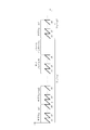
- FIG. 3 is a diagram illustrating an example of a chirp signal generated by the signal generation unit 21.
- the horizontal axis represents the elapsed time and the vertical axis represents the frequency.
- the signal generation unit 21 generates a linear chirp signal whose frequency changes linearly periodically.
- each chirp signal is shown as c1, c2, ..., C8.
- the frequency increases linearly with the passage of time.
- each of the 16 subframes such as the frame 1 and the frame 2 shown in FIG. 3 is included.
- a frame interval having a predetermined length may be included between the frames.
- One frame shown in FIG. 3 may have a length of, for example, about 30 milliseconds to 50 milliseconds.
- the same configuration may be used for the frame 2 and subsequent frames. Further, in FIG. 3, the frame 3 and subsequent frames may have the same configuration.
- the signal generation unit 21 may generate a transmission signal as an arbitrary number of frames. Further, in FIG. 3, some chirp signals are omitted. In this way, the relationship between the time and frequency of the transmission signal generated by the signal generation unit 21 may be stored in, for example, a storage unit 40.
- the electronic device 1 may transmit a transmission signal composed of subframes including a plurality of chirp signals. Further, the electronic device 1 according to the embodiment may transmit a transmission signal composed of frames including a predetermined number of subframes.
- the electronic device 1 will be described as transmitting a transmission signal having a frame structure as shown in FIG.
- the frame structure as shown in FIG. 3 is an example, and for example, the number of chirp signals contained in one subframe is not limited to eight.
- the signal generator 21 may generate subframes containing any number (eg, any number of) chirp signals.
- the subframe structure as shown in FIG. 3 is also an example, and for example, the subframe included in one frame is not limited to 16.
- the signal generator 21 may generate frames that include any number (eg, any number of) subframes.
- the signal generation unit 21 may generate signals having different frequencies.
- the signal generation unit 21 may generate a plurality of discrete signals having different bandwidths with different frequencies f.
- the synthesizer 22 raises the frequency of the signal generated by the signal generation unit 21 to a frequency in a predetermined frequency band.
- the synthesizer 22 may increase the frequency of the signal generated by the signal generation unit 21 to a frequency selected as the frequency of the transmission wave T transmitted from the transmission antenna 25.
- the frequency selected as the frequency of the transmission wave T transmitted from the transmission antenna 25 may be set by, for example, the control unit 10.
- the frequency selected as the frequency of the transmission wave T transmitted from the transmission antenna 25 may be the frequency selected by the control unit 10.
- the frequency selected as the frequency of the transmission wave T transmitted from the transmission antenna 25 may be stored in, for example, the storage unit 40.
- the signal whose frequency has been increased by the synthesizer 22 is supplied to the phase control unit 23 and the mixer 33.
- the signal whose frequency has been increased by the synthesizer 22 may be supplied to each of the plurality of phase control units 23.
- the signal whose frequency has been increased by the synthesizer 22 may be supplied to each mixer 33 in the plurality of receiving units 30.
- the phase control unit 23 controls the phase of the transmission signal supplied from the synthesizer 22. Specifically, the phase control unit 23 may adjust the phase of the transmission signal by appropriately advancing or delaying the phase of the signal supplied from the synthesizer 22 based on, for example, the control by the control unit 10. In this case, the phase control unit 23 may adjust the phase of each transmission signal based on the path difference of each transmission wave T transmitted from the plurality of transmission antennas 25. By appropriately adjusting the phase of each transmission signal by the phase control unit 23, the transmission waves T transmitted from the plurality of transmission antennas 25 strengthen each other in a predetermined direction to form a beam (beamforming).
- the correlation between the beamforming direction and the phase amount to be controlled of the transmission signals transmitted by the plurality of transmission antennas 25 may be stored in the storage unit 40, for example.
- the transmission signal whose phase is controlled by the phase control unit 23 is supplied to the amplifier 24.
- the amplifier 24 amplifies the power of the transmission signal supplied from the phase control unit 23, for example, based on the control by the control unit 10.
- the plurality of amplifiers 24 control the power (power) of the transmission signal supplied from the corresponding one of the plurality of phase control units 23, for example, by the control unit 10.
- Each may be amplified based on the above. Since the technique itself for amplifying the power of the transmission signal is already known, a more detailed description will be omitted.
- the amplifier 24 is connected to the transmitting antenna 25.
- the transmission antenna 25 outputs (transmits) the transmission signal amplified by the amplifier 24 as a transmission wave T.
- the plurality of transmitting antennas 25 may output (transmit) the transmission signals amplified by the corresponding ones of the plurality of amplifiers 24 as transmission waves T, respectively. Since the transmitting antenna 25 can be configured in the same manner as the transmitting antenna used in known radar technology, a more detailed description thereof will be omitted.
- the electronic device 1 is provided with the transmitting antenna 25, and can transmit a transmission signal (for example, a transmission chirp signal) as a transmission wave T from the transmission antenna 25.
- a transmission signal for example, a transmission chirp signal
- at least one of the functional units constituting the electronic device 1 may be housed in one housing.
- the one housing may have a structure that cannot be easily opened.
- the transmitting antenna 25, the receiving antenna 31, and the amplifier 24 are housed in one housing, and the housing cannot be easily opened.
- the transmitting antenna 25 transmits the transmitted wave T to the outside of the moving body 100 via a cover member such as a radar cover. You may.
- the radar cover may be made of a substance that allows electromagnetic waves to pass through, such as synthetic resin or rubber.
- This radar cover may be, for example, a housing of the sensor 5.
- a member such as a radar cover, it is possible to reduce the risk that the transmitting antenna 25 will be damaged or malfunction due to contact with the outside.
- the radar cover and housing may also be referred to as a radome.
- the electronic device 1 shown in FIG. 2 shows an example in which two transmitting antennas 25 are provided. However, in one embodiment, the electronic device 1 may include any number of transmitting antennas 25. On the other hand, in one embodiment, the electronic device 1 may include a plurality of transmitting antennas 25 when the transmitted wave T transmitted from the transmitting antenna 25 forms a beam in a predetermined direction. In one embodiment, the electronic device 1 may include any plurality of transmitting antennas 25. In this case, the electronic device 1 may be provided with a plurality of phase control units 23 and a plurality of amplifiers 24 in correspondence with the plurality of transmitting antennas 25.
- the plurality of phase control units 23 may control the phases of the plurality of transmitted waves supplied from the synthesizer 22 and transmitted from the plurality of transmitting antennas 25, respectively.
- the plurality of amplifiers 24 may amplify the power of the plurality of transmission signals transmitted from the plurality of transmission antennas 25, respectively.
- the sensor 5 may be configured to include a plurality of transmitting antennas. As described above, when the electronic device 1 shown in FIG. 2 is provided with a plurality of transmitting antennas 25, the electronic device 1 is configured to include a plurality of functional units necessary for transmitting the transmitted wave T from the plurality of transmitting antennas 25. Good.
- the receiving antenna 31 receives the reflected wave R.
- the reflected wave R is a transmitted wave T reflected by a predetermined object 200.
- the receiving antenna 31 may include a plurality of antennas, such as the receiving antenna 31A to the receiving antenna 31D. Since the receiving antenna 31 can be configured in the same manner as the receiving antenna used in the known radar technology, a more detailed description thereof will be omitted.
- the receiving antenna 31 is connected to the LNA 32.
- the received signal based on the reflected wave R received by the receiving antenna 31 is supplied to the LNA 32.
- the electronic device 1 has a reflected wave R in which a transmitted wave T transmitted as a transmission signal (transmission chirp signal) such as a chirp signal is reflected by a predetermined object 200 from a plurality of receiving antennas 31. Can be received.
- a transmission signal transmission chirp signal
- the reception signal based on the received reflected wave R is referred to as a reception chirp signal. That is, the electronic device 1 receives the received signal (for example, the received chirp signal) as the reflected wave R from the receiving antenna 31.
- the radar cover may be made of a substance that allows electromagnetic waves to pass through, such as synthetic resin or rubber.
- This radar cover may be, for example, a housing of the sensor 5.
- one sensor 5 may include, for example, at least one transmitting antenna 25 and at least one receiving antenna 31.
- one sensor 5 may include a plurality of transmitting antennas 25 and a plurality of receiving antennas 31.
- one radar sensor may be covered with a cover member such as one radar cover.
- the LNA 32 amplifies the received signal based on the reflected wave R received by the receiving antenna 31 with low noise.
- the LNA 32 may be used as a low noise amplifier, and amplifies the received signal supplied from the receiving antenna 31 with low noise.
- the received signal amplified by the LNA 32 is supplied to the mixer 33.
- the mixer 33 generates a beat signal by mixing (multiplying) the received signal of the RF frequency supplied from the LNA 32 with the transmission signal supplied from the synthesizer 22.
- the beat signal mixed by the mixer 33 is supplied to the IF unit 34.
- the IF unit 34 reduces the frequency of the beat signal to an intermediate frequency (IF (Intermediate Frequency) frequency) by performing frequency conversion to the beat signal supplied from the mixer 33.
- IF Intermediate Frequency
- the AD conversion unit 35 digitizes the analog beat signal supplied from the IF unit 34.
- the AD conversion unit 35 may be configured by any analog-to-digital conversion circuit (Analog to Digital Converter (ADC)).
- ADC Analog to Digital Converter
- the beat signal digitized by the AD conversion unit 35 is supplied to the distance FFT processing unit 11 of the control unit 10.
- each beat signal digitized by the plurality of AD conversion units 35 may be supplied to the distance FFT processing unit 11.
- the distance FFT processing unit 11 estimates the distance between the moving body 100 equipped with the electronic device 1 and the object 200 based on the beat signal supplied from the AD conversion unit 35.
- the distance FFT processing unit 11 may include, for example, a processing unit that performs a fast Fourier transform.
- the distance FFT processing unit 11 may be composed of an arbitrary circuit or chip that performs a fast Fourier transform (FFT) process.
- the distance FFT processing unit 11 performs FFT processing on the beat signal digitized by the AD conversion unit 35 (hereinafter, appropriately referred to as "distance FFT processing").
- the distance FFT processing unit 11 may perform FFT processing on the complex signal supplied from the AD conversion unit 35.
- the beat signal digitized by the AD conversion unit 35 can be represented as a time change in signal strength (electric power).
- the distance FFT processing unit 11 can express the signal strength (power) corresponding to each frequency by performing FFT processing on such a beat signal.
- the distance FFT processing unit 11 may determine that the predetermined object 200 is at a distance corresponding to the peak.
- CFAR Constant False Alarm Rate
- the electronic device 1 detects the object 200 that reflects the transmission wave T based on the transmission signal transmitted as the transmission wave T and the reception signal received as the reflection wave R. be able to.
- Distance FFT processing unit 11 can estimate the distance to a predetermined object based on one chirp signal (for example, c1 shown in FIG. 3). That is, the electronic device 1 can measure (estimate) the distance L shown in FIG. 1 by performing the distance FFT process. Since the technique itself for measuring (estimating) the distance to a predetermined object by performing FFT processing on the beat signal is known, a more detailed description will be simplified or omitted as appropriate.
- the result of the distance FFT processing performed by the distance FFT processing unit 11 (for example, distance information) may be supplied to the speed FFT processing unit 12. Further, the result of the distance FFT processing performed by the distance FFT processing unit 11 may be supplied to the object detection unit 14.
- the velocity FFT processing unit 12 estimates the relative velocity between the moving body 100 equipped with the electronic device 1 and the object 200 based on the beat signal subjected to the distance FFT processing by the distance FFT processing unit 11.
- the speed FFT processing unit 12 may include, for example, a processing unit that performs a fast Fourier transform.
- the speed FFT processing unit 12 may be composed of an arbitrary circuit or chip that performs a fast Fourier transform (FFT) process.
- FFT fast Fourier transform
- the speed FFT processing unit 12 further performs FFT processing on the beat signal subjected to the distance FFT processing by the distance FFT processing unit 11 (hereinafter, appropriately referred to as "speed FFT processing").
- the velocity FFT processing unit 12 may perform FFT processing on the complex signal supplied from the distance FFT processing unit 11.
- the velocity FFT processing unit 12 can estimate the relative velocity with a predetermined object based on the subframe of the chirp signal (for example, the subframe 1 shown in FIG. 3).
- a plurality of vectors can be generated.
- the relative velocity with a predetermined object can be estimated by obtaining the phase of the peak in the result of performing the velocity FFT processing on these plurality of vectors.
- the electronic device 1 can measure (estimate) the relative velocity between the moving body 100 shown in FIG. 1 and the predetermined object 200 by performing the velocity FFT process. Since the technique itself for measuring (estimating) the relative velocity with a predetermined object by performing the velocity FFT process on the result of performing the distance FFT process is known, a more detailed description may be simplified or omitted as appropriate. To do.
- the result of the velocity FFT processing performed by the velocity FFT processing unit 12 (for example, velocity information) may be supplied to the arrival angle estimation unit 13. Further, the result of the velocity FFT processing performed by the velocity FFT processing unit 12 may be supplied to the object detection unit 14.
- the arrival angle estimation unit 13 estimates the direction in which the reflected wave R arrives from the predetermined object 200 based on the result of the velocity FFT processing performed by the velocity FFT processing unit 12.
- the electronic device 1 can estimate the direction in which the reflected wave R arrives by receiving the reflected wave R from the plurality of receiving antennas 31.
- the plurality of receiving antennas 31 are arranged at predetermined intervals. In this case, the transmitted wave T transmitted from the transmitting antenna 25 is reflected by the predetermined object 200 to become the reflected wave R, and the plurality of receiving antennas 31 arranged at predetermined intervals each receive the reflected wave R.
- the arrival angle estimation unit 13 estimates the direction in which the reflected wave R arrives at the receiving antenna 31 based on the phase of the reflected wave R received by each of the plurality of receiving antennas 31 and the path difference of each reflected wave R. can do. That is, the electronic device 1 can measure (estimate) the arrival angle ⁇ shown in FIG. 1 based on the result of performing the speed FFT process.
- MUSIC MUltiple SIgnal Classification
- ESPRIT Estimat of Signal Parameters via Rotational Invariance Technique
- the object detection unit 14 detects an object existing in the range in which the transmission wave T is transmitted, based on information supplied from at least one of the distance FFT processing unit 11, the velocity FFT processing unit 12, and the arrival angle estimation unit 13. To detect.
- the object detection unit 14 may perform object detection by performing, for example, clustering processing based on the supplied distance information, velocity information, and angle information.
- clustering processing for example, DBSCAN (Density-based spatial clustering of applications with noise) is known.
- the average power of the points constituting the detected object may be calculated.
- the distance information, velocity information, angle information, and electric power information of the object detected by the object detection unit 14 may be supplied to the detection output control unit 15.
- the distance information, the velocity information, the angle information, and the electric power information of the object detected by the object detection unit 14 may be supplied to the ECU 50.
- communication may be performed using a communication interface such as CAN (Controller Area Network).
- the detection output control unit 15 controls when notifying the ECU 50 of the detection by the object detection unit 14. More specifically, the detection output control unit 15 controls when the information detected by the object detection unit 14 is output to the ECU 50. For example, the detection output control unit 15 may control whether or not to output the information detected by the object detection unit 14 to the ECU 50. Specifically, the detection output control unit 15 may or may not output the information of the object to the ECU 50 according to the information of the object detected by the object detection unit 14. Further, the detection output control unit 15 may control the order of the outputs when the information detected by the object detection unit 14 is output to the ECU 50. For example, when a plurality of objects are detected by the object detection unit 14, the detection output control unit 15 determines the order in which the information of the plurality of objects is output to the ECU 50 according to the information of the plurality of objects. Good.
- the detection output control unit 15 can acquire information on the distance, speed, angle, power, etc. of the object detected by the object detection unit 14. Therefore, the detection output control unit 15 may calculate the time required for the object 200 reflecting the transmitted wave to reach the moving body 100 based on the information on the distance and velocity (relative velocity) of the detected object. .. As described above, in the electronic device 1 according to the embodiment, the control unit 10 (for example, the object detection unit 14) determines the distance and the relative speed between the object 200 and the moving body 100 based on the transmission signal and the reception signal. You may estimate.
- the control unit 10 (detection output control unit 15) is based on the estimated distance and relative speed until the object 200 that reflects the transmitted wave reaches the moving body 100. Time may be calculated. In this way, the control unit 10 (detection output control unit 15) notifies the mobile body control unit 50 of the detection of the object 200 according to the time until the object 200 reflecting the transmitted wave reaches the mobile body 100. To do. The operation of the detection output control unit 15 will be described later.
- the ECU 50 (mobile body control unit 50) included in the electronic device 1 according to the embodiment can control the operation of the entire mobile body 100, including the control of each functional unit constituting the mobile body 100.
- the ECU 50 may include at least one processor, such as a CPU (Central Processing Unit), in order to provide control and processing power to perform various functions.
- the ECU 50 may be realized collectively by one processor, by several processors, or by individual processors.
- the processor may be implemented as a single integrated circuit.
- the integrated circuit is also called an IC (Integrated Circuit).
- the processor may be implemented as a plurality of communicably connected integrated circuits and discrete circuits.
- the processor may be implemented on the basis of various other known techniques.
- the ECU 50 may be configured as, for example, a CPU and a program executed by the CPU.
- the ECU 50 may appropriately include a memory required for the operation of the ECU 50.
- at least a part of the function of the control unit 10 may be a function of the ECU 50, or at least a part of the function of the ECU 50 may be a function of the control unit 10.
- the ECU (moving body control unit) 50 may acquire the speed of the moving body 100 (for example, a moving speed such as a running speed).
- the ECU 50 may acquire information on the speed of the moving body 100 from a speedometer mounted on the moving body 100.
- the ECU 50 may estimate the speed of the mobile body 100 based on the position information acquired from the GPS (Global Positioning System) system or the like mounted on the mobile body 100.
- the ECU 50 may acquire information on the speed of the moving body 100 by any means.
- the ECU 50 may supply the speed information of the moving body 100 acquired in this way to the detection output control unit 15 and the like.
- the electronic device 1 shown in FIG. 2 includes two transmitting antennas 25 and four receiving antennas 31.
- the electronic device 1 according to the embodiment may include an arbitrary number of transmitting antennas 25 and an arbitrary number of receiving antennas 31.
- the electronic device 1 can be considered to include a virtual antenna array virtually composed of eight antennas.
- the electronic device 1 may receive the reflected wave R of the 16 subframes shown in FIG. 3 by using, for example, eight virtual antennas.
- the electronic device 1 according to the embodiment transmits the transmitted wave from the transmitting antenna, and receives the reflected wave reflected by the object or the like from the receiving antenna. Then, the electronic device 1 according to the embodiment can detect an object that reflects the transmitted wave based on the transmitted signal and / or the received signal.
- the ECU 50 can issue a predetermined alarm to the operator of the moving body 100 by receiving the information of the object, or notify the operator of the information of the object by sound and / or display. Further, the ECU 50 can also control the operation of the moving body 100 to assist the operator in maneuvering by receiving the information of the object.
- the electronic device 1 may preferentially output information on the objects that are considered to be important to the operator to the ECU 50. For example, when a plurality of objects are detected, the electronic device 1 may output the information of the objects having a short distance to the moving body 100 to the ECU 50 with priority. Further, for example, when a plurality of objects are detected, the electronic device 1 may output the information of the object having a large signal intensity (electric power) of the reflected wave to the ECU 50 with priority.
- the information of an object having a short distance to the moving body 100 is preferentially output to the ECU 50, an object such as a wall existing in the vicinity of the moving body 100 is detected, and the information of the wall is output to the ECU 50. It is possible. In this case, the information of the object existing in the distance of the moving body 100 may not be output to the ECU 50 (or may be output as low priority information). Further, if the information of an object having a high signal intensity of the reflected wave is preferentially output to the ECU 50, the information of the object may not be output to the ECU 50 even if an object having a low reflectance is detected. In this case, information on an object having low reflectance, such as a pedestrian, may not be output to the ECU 50 (or may be notified as low priority information).
- the electronic device 1 when a communication interface such as CAN is adopted for communication between the sensor 5 and the ECU 50, the communication speed with the ECU 50 is often limited. Therefore, when a communication interface such as CAN is adopted, it is often difficult to communicate a large amount of detected object information in a short time.
- the electronic device 1 according to the embodiment preferentially outputs the information of the object having a high risk of colliding with the moving body 100 to the ECU 50.
- the operation of the electronic device 1 according to the embodiment will be described more specifically.
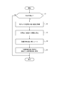
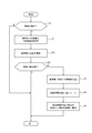
- FIG. 4 is a flowchart illustrating an example of the operation of the electronic device 1 according to the embodiment.
- the electronic device 1 is operating up to the front of the object detection unit 14 of the control unit 10 shown in FIG. That is, at the time when the operation shown in FIG. 4 starts, it is assumed that the electronic device 1 transmits the transmitted wave from the transmitting unit 20 and receives the reflected wave reflected by the transmitted wave by the receiving unit 30. Further, it is assumed that the control unit 10 has started signal processing based on the transmission signal and the reception signal at the time when the operation shown in FIG. 4 starts.
- the distance FFT processing unit 11 performs the distance FFT processing on the beat signal
- the speed FFT processing unit 12 performs the speed FFT processing on the result of the distance FFT processing
- the arrival angle estimation unit 13 performs the speed FFT processing.
- the arrival angle may be estimated based on the result of the speed FFT process.
- the object detection unit 14 determines whether or not an object that reflects the transmission wave has been detected based on the transmission signal and the reception signal (step S1). In step S1, the object detection unit 14 detects the object based on the information supplied from at least one of the distance FFT processing unit 11, the velocity FFT processing unit 12, and the arrival angle estimation unit 13 as described above. You can. If it is not determined that the object has been detected in step S1, the control unit 10 ends the operation shown in FIG.
- the detection output control unit 15 acquires the distance and relative velocity of the detected object (step S2).
- the “distance of the detected object” acquired in step S2 may be, for example, the distance between the moving body 100 on which the electronic device 1 is mounted and the detected object 200.
- the “relative velocity (of the detected object)" acquired in step S2 may be, for example, the relative velocity between the moving body 100 on which the electronic device 1 is mounted and the detected object 200.
- the distance information, the velocity information, the angle information, and the electric power information of the object detected by the object detection unit 14 may be supplied to the detection output control unit 15. Therefore, the detection output control unit 15 may acquire information from the object detection unit 14 in step S2.
- the detection output control unit 15 may acquire information from at least one of the distance FFT processing unit 11, the speed FFT processing unit 12, and the arrival angle estimation unit 13. Further, in step S2, the detection output control unit 15 may acquire the information temporarily stored in the storage unit 40.
- the detection output control unit 15 estimates (calculates) the time it takes for the detected object to reach the moving body 100, which is the own vehicle (step S3). For example, in step S3, the detection output control unit 15 may calculate the time by dividing the distance by the relative speed.
- the detection output control unit 15 estimates (calculates) the time to reach the moving body 100 in step S3 for each of the plurality of objects.
- the time calculated (estimated) in step S3 is also simply referred to as “arrival time”. This arrival time can be assumed to be the time until the detected object collides with the moving body 100 on which the electronic device 1 is mounted.
- the arrival time is the same latitude and the same latitude and the same latitude as the moving body 100 on which the electronic device 1 is mounted. It may be the time required to reach the longitude P or the coordinate position X.
- the coordinate position X may be any one-dimensional coordinate, two-dimensional coordinate, or three-dimensional coordinate.
- the detection output control unit 15 sorts the detected plurality of objects in ascending order of arrival time (step S4).
- the detection output control unit 15 may sort the plurality of objects from the one having the shortest arrival time calculated for each of the plurality of detected objects.
- the detection output control unit 15 When a plurality of objects are sorted in step S4, the detection output control unit 15 notifies the ECU 50 from the plurality of objects having the shortest calculated arrival time (step S5). In step S5, the detection output control unit 15 may output the information of the detected object to the ECU 50 from the plurality of the objects having the shortest calculated arrival time.
- the control unit 10 (detection output control unit 15) waits until the object 200 that reflects the transmission wave reaches the moving body 100 based on the transmission signal and the reception signal. Estimate the time of. Further, in the electronic device 1 according to the embodiment, the control unit 10 (detection output control unit 15) detects the object 200 according to the time until the object 200 reflecting the transmitted wave reaches the moving body 100. Notify the ECU 50. Specifically, the control unit 10 (detection output control unit 15) may notify the ECU 50 of the detection of the object 200 because the time required for the object 200 reflecting the transmitted wave to reach the moving body 100 is short. Good.
- control unit 10 detection output control unit 15
- preferential notification may include the meaning of notifying in order.
- the operation shown in FIG. 4 may be repeatedly executed, for example, at a predetermined timing or irregularly. Further, in one embodiment, the detection output control unit 15 may notify the ECU 50 of the detection of the object with priority given to the object having the shortest arrival time, for example, for each frame of the transmission signal. In this way, the detection output control unit 15 calculates the time until the object collides based on the distance and the relative velocity of the object, and outputs the information of the object having the short collision time in the frame of the transmission signal to the ECU 50. be able to. Therefore, the ECU 50 can preferentially process the information of the object having a high risk of colliding with the moving body 100.
- the ECU 50 gives priority to an object having a high risk of collision to issue a predetermined alarm to the operator of the moving body 100, or notifies the operator of the information of the object by sound and / or display. be able to. Further, the ECU 50 can assist the operator in maneuvering by controlling the operation of the moving body 100, giving priority to the object having a high risk of collision.
- the priority of outputting the information (message, etc.) of the object notified to the ECU 50 is determined. Further, according to the electronic device 1 according to the embodiment, the information on the object having a high risk of colliding with the moving body 100 is preferentially notified to the ECU 50. Therefore, according to the electronic device 1 according to the embodiment, it is possible to preferentially recognize an object having a high risk of collision and notify the ECU 50. Therefore, according to the electronic device 1 according to the embodiment, the safety of the moving body can be improved. Further, according to the electronic device 1 according to the embodiment, the object having a high risk of collision is preferentially detected and notified to the ECU 50.
- the electronic device 1 even if a communication interface having a limited communication speed such as CAN is used for communication with the ECU 50, an object having a high risk of colliding with the mobile body 100 is used. It can be preferentially detected from the information of the above and output to the ECU 50.
- a communication interface having a limited communication speed such as CAN
- FIG. 5 is a flowchart illustrating another example of the operation of the electronic device 1 according to the embodiment.
- the operation shown in FIG. 5 is a partial modification of the operation shown in FIG. Therefore, hereinafter, the same or similar description as already described in FIG. 4 will be simplified or omitted as appropriate.
- the electronic device 1 acquires the traveling speed of the own vehicle, determines whether or not it is a stationary object from the relative speed of the object, and in the case of a stationary object, the ECU 50. Do not notify (or lower the priority of notification).
- the detection output control unit 15 acquires, for example, the traveling speed of the moving body 100, which is the own vehicle (step S21).
- the detection output control unit 15 may acquire the traveling speed of the moving body 100 from, for example, the ECU 50.
- the ECU 50 may acquire the speed of the moving body 100 (for example, a moving speed such as a running speed).
- the detection output control unit 15 determines whether or not the detected object is stationary (step S22).
- the object is stationary means that the moving body 100 is stationary with respect to the traveling road surface or the like. That is, “the object is stationary” means that the object is not moving on the road surface on which the moving body 100 is traveling. For example, suppose that the traveling speed of the moving body 100 is 50 km / h when the detected object is moving away from the moving body 100 at a relative speed of 50 km / h. In this case, in step S22, the detection output control unit 15 can determine that the object is stationary.
- the control unit 10 ends the operation shown in FIG.
- the control unit 10 performs the operations after step S3. That is, in the operation shown in FIG. 5, when a non-resting object is detected, the ECU 50 is notified in consideration of the priority as described above. On the other hand, in the operation shown in FIG. 5, even if a stationary object is detected, the ECU 50 is not notified. Further, in this case, when a stationary object is detected, the priority of notifying the ECU 50 may be set low.
- the control unit 10 estimates the relative speed between the object 200 and the moving body 100 based on the transmission signal and the reception signal. You may. Further, in the electronic device 1 according to the embodiment, the control unit 10 (detection output control unit 15) determines that the object 200 is based on the relative speed between the object 200 and the moving body 100 and the speed of the moving body 100. It may be determined whether or not it is stationary. Then, in the electronic device 1 according to the embodiment, when the control unit 10 (detection output control unit 15) determines that the object 200 is stationary, the control unit 10 does not have to notify the ECU 50 of the detection of the object 200. Good.
- the information on the moving object having a high risk of colliding with the moving body 100 is preferentially notified to the ECU 50. Therefore, according to the electronic device 1 according to the embodiment, it is possible to preferentially recognize an object having a high risk of collision and notify the ECU 50. Therefore, according to the electronic device 1 according to the embodiment, the safety of the moving body can be improved.
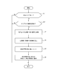
- FIG. 6 is a flowchart illustrating another example of the operation of the electronic device 1 according to the embodiment.
- the operation shown in FIG. 6 is the same as the operation shown in FIG. 5, and is a partial modification of the operation shown in FIG. Therefore, hereinafter, the same or similar description as already described in FIG. 4 or FIG. 5 will be simplified or omitted as appropriate.
- the control unit 10 determines whether or not a detection area for transmitting a transmitted wave from the transmitting antenna 25 to detect an object is set (step S31). If the detection area is not set in step S31, the control unit 10 ends the operation shown in FIG.
- the detection areas of the present disclosure include, for example, an area in a predetermined range in front of the moving body 100, an area in a traveling lane of the moving body 100, an area other than the traveling lane of the moving body 100, and an area in a predetermined range behind the moving body 100.
- An appropriate area such as an area in a predetermined angle range on the side of the moving body 100 and an area in any combination thereof can be used.
- the object detection unit 14 determines whether or not an object that reflects the transmitted wave is detected in the area (step S32). In step S32, as described above, the object detection unit 14 detects the object based on the information supplied from at least one of the distance FFT processing unit 11, the velocity FFT processing unit 12, and the arrival angle estimation unit 13. You can.
- step S32 If it is not determined in step S32 that an object has been detected in the detection area, the control unit 10 ends the operation shown in FIG. On the other hand, when it is determined in step S32 that the object is detected in the detection area, the control unit 10 performs the operations after step S2. That is, in the operation shown in FIG. 6, when an object is detected in the area set to detect the object by the transmitted wave, the ECU 50 is notified in consideration of the priority as described above.
- the control unit 10 detects the object 200 by the ECU 50. May be notified to.
- the information on the object having a high risk of colliding with the moving body 100 is preferentially notified to the ECU 50. Therefore, according to the electronic device 1 according to the embodiment, it is possible to preferentially recognize an object having a high risk of collision and notify the ECU 50. Therefore, according to the electronic device 1 according to the embodiment, the safety of the moving body can be improved. Further, according to the electronic device 1 according to the embodiment, only the objects detected in the area set to detect the objects by the transmitted wave are notified to the ECU 50 in consideration of the priority as described above. To. Therefore, the amount of information communicated from the control unit 10 to the ECU 50 can be reduced.
- each functional unit, each means, each step, etc. are added to other embodiments so as not to be logically inconsistent, or each functional unit, each means, each step, etc. of other embodiments. Can be replaced with. Further, in each embodiment, it is possible to combine or divide a plurality of each functional unit, each means, each step, and the like into one. Further, each of the above-described embodiments of the present disclosure is not limited to faithful implementation of each of the embodiments described above, and each feature may be combined or a part thereof may be omitted as appropriate. You can also do it.
- the object may be detected in the object detection range determined by the plurality of sensors 5.
- beamforming may be performed toward a determined object detection range by a plurality of sensors 5.
- the above-described embodiment is not limited to the implementation as the electronic device 1.
- the above-described embodiment may be implemented as a control method for a device such as the electronic device 1.
- the above-described embodiment may be implemented as a program executed by a device such as the electronic device 1.
- the electronic device 1 according to the embodiment may include at least a part of only one of the sensor 5 and the control unit 10, for example, as the minimum configuration.
- the electronic device 1 according to the embodiment is at least one of a signal generation unit 21, a synthesizer 22, a phase control unit 23, an amplifier 24, and a transmission antenna 25, as shown in FIG. 2, in addition to the control unit 10. May be included as appropriate.
- the electronic device 1 according to the embodiment has at least one of the receiving antenna 31, LNA 32, mixer 33, IF unit 34, and AD conversion unit 35 in place of or together with the above-mentioned functional unit. It may be included as appropriate.
- the electronic device 1 according to the embodiment may include a storage unit 40.
- the electronic device 1 according to the embodiment can adopt various configuration modes. Further, when the electronic device 1 according to the embodiment is mounted on the mobile body 100, for example, at least one of the above-mentioned functional units may be installed in an appropriate place such as inside the mobile body 100. On the other hand, in one embodiment, for example, at least one of the transmitting antenna 25 and the receiving antenna 31 may be installed outside the mobile body 100.
Abstract
This electronic device comprises: a transmission antenna for transmitting a transmission wave, a reception antenna for receiving a reflected wave resulting from the reflection of the transmission wave, and a control unit. The control unit detects an object that has reflected the transmission wave on the basis of a transmission signal transmitted as the transmission wave and a reception signal received as the reflected wave. The control unit estimates the time until the object arrives at a moving body on the basis of the transmission signal and reception signal and, in accordance with the estimated time, notifies a moving body control unit for controlling the moving body of the detection of the object.
Description
本出願は、2019年5月29日に日本国に特許出願された特願2019-100702の優先権を主張するものであり、この先の出願の開示全体を、ここに参照のために取り込む。
This application claims the priority of Japanese Patent Application No. 2019-100702, which was filed in Japan on May 29, 2019, and the entire disclosure of future applications is incorporated herein by reference.
本開示は、電子機器、電子機器の制御方法、及びプログラムに関する。
This disclosure relates to electronic devices, electronic device control methods, and programs.
例えば自動車に関連する産業などの分野において、自車両と所定の物体との間の距離などを測定する技術が重要視されている。特に、近年、ミリ波のような電波を送信し、障害物などの物体に反射した反射波を受信することで、物体との間の距離などを測定するレーダ(RADAR(Radio Detecting and Ranging))の技術が、種々研究されている。このような距離などを測定する技術の重要性は、運転者の運転をアシストする技術、及び、運転の一部又は全部を自動化する自動運転に関連する技術の発展に伴い、今後ますます高まると予想される。
For example, in fields such as automobile-related industries, technology for measuring the distance between the own vehicle and a predetermined object is regarded as important. In particular, in recent years, radar (RADAR (Radio Detecting and Langing)) measures the distance to an object by transmitting radio waves such as millimeter waves and receiving reflected waves reflected by objects such as obstacles. Techniques have been studied in various ways. The importance of technology for measuring such distances will increase in the future with the development of technology that assists the driver's driving and technology related to autonomous driving that automates part or all of the driving. is expected.
また、送信された電波が所定の物体に反射した反射波を受信することで、当該物体の存在を検出する技術について、種々の提案がされている。例えば特許文献1は、特定の周期で直線FM変調を行った送信信号を目標物体に照射し、目標物体からの受信信号との差によりビート信号を検出し、この信号の周波数分析から距離・速度計測を行うFM-CWレーダ装置を開示している。
In addition, various proposals have been made for a technique for detecting the existence of a predetermined object by receiving the reflected wave reflected by the transmitted radio wave. For example, Patent Document 1 irradiates a target object with a transmission signal that has undergone linear FM modulation at a specific cycle, detects a beat signal based on the difference from the reception signal from the target object, and analyzes the frequency and speed of this signal. It discloses an FM-CW radar device that performs measurement.
一実施形態に係る電子機器は、移動体に搭載される電子機器であって、送信波を送信する送信アンテナと、前記送信波が反射された反射波を受信する受信アンテナと、制御部と、を備える。
前記制御部は、前記送信波として送信される送信信号及び前記反射波として受信される受信信号に基づいて、前記送信波を反射する物体を検出する。
前記制御部は、前記送信信号及び前記受信信号に基づいて前記物体が前記移動体に到達するまでの時間を推定し、前記移動体を制御する移動体制御部に前記物体の検出を前記時間に応じて通知する。 The electronic device according to the embodiment is an electronic device mounted on a mobile body, and includes a transmitting antenna for transmitting a transmitted wave, a receiving antenna for receiving the reflected wave reflected by the transmitted wave, a control unit, and the like. To be equipped.
The control unit detects an object that reflects the transmitted wave based on the transmitted signal transmitted as the transmitted wave and the received signal received as the reflected wave.
The control unit estimates the time until the object reaches the moving body based on the transmission signal and the reception signal, and the moving body control unit that controls the moving body detects the object at the time. Notify accordingly.
一実施形態に係る電子機器の制御方法は、移動体に搭載される電子機器の制御方法であって、以下のステップを含む。
(1)送信アンテナから送信波を送信するステップ
(2)前記送信波が反射された反射波を受信アンテナから受信するステップ
(3)前記送信波として送信される送信信号及び前記反射波として受信される受信信号に基づいて、前記送信波を反射する物体を検出するステップ
(4)前記送信信号及び前記受信信号に基づいて、前記物体が前記移動体に到達するまでの時間を推定するステップ
(5)前記移動体を制御する移動体制御部に前記物体の検出を前記時間に応じて通知するステップ The method for controlling an electronic device according to an embodiment is a method for controlling an electronic device mounted on a mobile body, and includes the following steps.
(1) Step of transmitting the transmitted wave from the transmitting antenna (2) Step of receiving the reflected wave reflected by the transmitted wave from the receiving antenna (3) The transmitted signal transmitted as the transmitted wave and received as the reflected wave Step of detecting an object reflecting the transmitted wave based on the received signal (4) Step of estimating the time required for the object to reach the moving body based on the transmitted signal and the received signal (5) ) A step of notifying the moving body control unit that controls the moving body of the detection of the object according to the time.
一実施形態に係るプログラムは、移動体に搭載される電子機器に、上記のステップ(1)乃至(5)を実行させる。
The program according to one embodiment causes an electronic device mounted on the mobile body to execute the above steps (1) to (5).
送信された送信波が所定の物体に反射した反射波を受信することにより、当該物体を検出する技術を用いて、例えば自動車のような移動体の安全性を向上させることが望ましい。本開示の目的は、移動体の安全性を向上し得る電子機器、電子機器の制御方法、及びプログラムを提供することにある。一実施形態によれば、移動体の安全性を向上し得る電子機器、電子機器の制御方法、及びプログラムを提供することができる。以下、一実施形態について、図面を参照して詳細に説明する。
It is desirable to improve the safety of a moving object such as an automobile by using a technique for detecting a predetermined object by receiving the reflected wave reflected by the transmitted transmitted wave. An object of the present disclosure is to provide electronic devices, control methods and programs for electronic devices that can improve the safety of mobile objects. According to one embodiment, it is possible to provide an electronic device, a control method for the electronic device, and a program that can improve the safety of the moving body. Hereinafter, one embodiment will be described in detail with reference to the drawings.
一実施形態に係る電子機器は、例えば自動車などのような乗り物(移動体)に搭載されることで、当該移動体の周囲に存在する所定の物体を検出することができる。このために、一実施形態に係る電子機器は、移動体に設置した送信アンテナから、移動体の周囲に送信波を送信することができる。また、一実施形態に係る電子機器は、移動体に設置した受信アンテナから、送信波が反射された反射波を受信することができる。送信アンテナ及び受信アンテナの少なくとも一方は、例えば移動体に設置されたレーダセンサ等に備えられてもよい。
The electronic device according to one embodiment can detect a predetermined object existing around the moving body by being mounted on a vehicle (moving body) such as an automobile or the like. Therefore, the electronic device according to the embodiment can transmit a transmitted wave around the mobile body from a transmitting antenna installed on the mobile body. Further, the electronic device according to the embodiment can receive the reflected wave in which the transmitted wave is reflected from the receiving antenna installed in the mobile body. At least one of the transmitting antenna and the receiving antenna may be provided in, for example, a radar sensor installed in a moving body.
以下、典型的な例として、一実施形態に係る電子機器が、乗用車のような自動車に搭載される構成について説明する。しかしながら、一実施形態に係る電子機器が搭載されるのは、自動車に限定されない。一実施形態に係る電子機器は、バス、トラック、オートバイ、自転車、船舶、航空機、トラクターなどの農作業装置、除雪車、清掃車、パトカー、救急車、及びドローンなど、種々の移動体に搭載されてよい。また、一実施形態に係る電子機器が搭載されるのは、必ずしも自らの動力で移動する移動体にも限定されない。例えば、一実施形態に係る電子機器が搭載される移動体は、トラクターにけん引されるトレーラー部分などとしてもよい。一実施形態に係る電子機器は、センサ及び所定の物体の少なくとも一方が移動し得るような状況において、センサと物体との間の距離などを測定することができる。また、一実施形態に係る電子機器は、センサ及び物体の双方が静止していても、センサと物体との間の距離などを測定することができる。
Hereinafter, as a typical example, a configuration in which the electronic device according to one embodiment is mounted on an automobile such as a passenger car will be described. However, the electronic device according to the embodiment is not limited to the automobile. The electronic device according to one embodiment may be mounted on various moving objects such as agricultural work devices such as buses, trucks, motorcycles, bicycles, ships, aircrafts, and tractors, snowplows, cleaning vehicles, police cars, ambulances, and drones. .. Further, the electronic device according to the embodiment is not necessarily mounted on a moving body that moves by its own power. For example, the moving body on which the electronic device according to the embodiment is mounted may be a trailer portion towed by a tractor. The electronic device according to the embodiment can measure the distance between the sensor and the object in a situation where at least one of the sensor and a predetermined object can move. Further, the electronic device according to the embodiment can measure the distance between the sensor and the object even if both the sensor and the object are stationary.
まず、一実施形態に係る電子機器による物体の検出の例を説明する。
First, an example of detecting an object by an electronic device according to an embodiment will be described.
図1は、一実施形態に係る電子機器の使用態様を説明する図である。図1は、一実施形態に係る送信アンテナ及び受信アンテナを備えるセンサを、移動体に設置した例を示している。
FIG. 1 is a diagram illustrating a usage mode of the electronic device according to the embodiment. FIG. 1 shows an example in which a sensor including a transmitting antenna and a receiving antenna according to an embodiment is installed on a moving body.
図1に示す移動体100には、一実施形態に係る送信アンテナ及び受信アンテナを備えるセンサ5が設置されている。また、図1に示す移動体100は、一実施形態に係る電子機器1を搭載(例えば内蔵)しているものとする。電子機器1の具体的な構成については後述する。センサ5は、例えば送信アンテナ及び受信アンテナの少なくとも一方を備えるものとしてよい。また、センサ5は、電子機器1に含まれる制御部10(図2)の少なくとも一部など、他の機能部の少なくともいずれかを、適宜含んでもよい。図1に示す移動体100は、乗用車のような自動車の車両としてよいが、任意のタイプの移動体としてよい。図1において、移動体100は、例えば図に示すY軸正方向(進行方向)に移動(走行又は徐行)していてもよいし、他の方向に移動していてもよいし、また移動せずに静止していてもよい。
The mobile body 100 shown in FIG. 1 is provided with a sensor 5 including a transmitting antenna and a receiving antenna according to the embodiment. Further, it is assumed that the mobile body 100 shown in FIG. 1 is equipped (for example, built-in) with the electronic device 1 according to the embodiment. The specific configuration of the electronic device 1 will be described later. The sensor 5 may include, for example, at least one of a transmitting antenna and a receiving antenna. Further, the sensor 5 may appropriately include at least one of other functional units such as at least a part of the control unit 10 (FIG. 2) included in the electronic device 1. The moving body 100 shown in FIG. 1 may be an automobile vehicle such as a passenger car, but may be any type of moving body. In FIG. 1, the moving body 100 may, for example, move (run or slow) in the positive direction (traveling direction) of the Y axis shown in the figure, move in another direction, or move. It may be stationary without.
図1に示すように、移動体100には、送信アンテナを備えるセンサ5が設置されている。図1に示す例において、送信アンテナ及び受信アンテナを備えるセンサ5は、移動体100の前方に1つだけ設置されている。ここで、センサ5が移動体100に設置される位置は、図1に示す位置に限定されるものではなく、適宜、他の位置としてもよい。例えば、図1に示すようなセンサ5を、移動体100の左側、右側、及び/又は、後方などに設置してもよい。また、このようなセンサ5の個数は、移動体100における測定の範囲及び/又は精度など各種の条件(又は要求)に応じて、1つ以上の任意の数としてよい。センサ5は、移動体100の内部に設置されているとしてもよい。移動体100の内部とは、例えばバンパー内の空間、ボディ内の空間、ヘッドライト内の空間、又は運転スペースの空間などでよい。
As shown in FIG. 1, a sensor 5 provided with a transmitting antenna is installed in the moving body 100. In the example shown in FIG. 1, only one sensor 5 including a transmitting antenna and a receiving antenna is installed in front of the moving body 100. Here, the position where the sensor 5 is installed on the moving body 100 is not limited to the position shown in FIG. 1, and may be another position as appropriate. For example, the sensor 5 as shown in FIG. 1 may be installed on the left side, the right side, and / or the rear of the moving body 100. Further, the number of such sensors 5 may be any one or more depending on various conditions (or requirements) such as the measurement range and / or accuracy of the moving body 100. The sensor 5 may be installed inside the moving body 100. The inside of the moving body 100 may be, for example, a space in a bumper, a space in a body, a space in a headlight, a space in a driving space, or the like.
センサ5は、送信アンテナから送信波として電磁波を送信する。例えば移動体100の周囲に所定の物体(例えば図1に示す物体200)が存在する場合、センサ5から送信された送信波の少なくとも一部は、当該物体によって反射されて反射波となる。そして、このような反射波を例えばセンサ5の受信アンテナによって受信することにより、移動体100に搭載された電子機器1は、当該物体を検出することができる。
The sensor 5 transmits an electromagnetic wave as a transmission wave from the transmission antenna. For example, when a predetermined object (for example, the object 200 shown in FIG. 1) exists around the moving body 100, at least a part of the transmitted wave transmitted from the sensor 5 is reflected by the object to become a reflected wave. Then, by receiving such a reflected wave by, for example, the receiving antenna of the sensor 5, the electronic device 1 mounted on the mobile body 100 can detect the object.
送信アンテナを備えるセンサ5は、典型的には、電波を送受信するレーダ(RADAR(Radio Detecting and Ranging))センサとしてよい。しかしながら、センサ5は、レーダセンサに限定されない。一実施形態に係るセンサ5は、例えば光波によるLIDAR(Light Detection and Ranging、Laser Imaging Detection and Ranging)の技術に基づくセンサとしてもよい。これらのようなセンサは、例えばパッチアンテナなどを含んで構成することができる。RADAR及びLIDARのような技術は既に知られているため、詳細な説明は、適宜、簡略化又は省略することがある。
The sensor 5 provided with a transmitting antenna may typically be a radar (RADAR (Radio Detecting and Ringing)) sensor that transmits and receives radio waves. However, the sensor 5 is not limited to the radar sensor. The sensor 5 according to one embodiment may be, for example, a sensor based on the technology of LIDAR (Light Detection and Ringing, Laser Imaging Detection and Ringing) using light waves. A sensor such as these can be configured to include, for example, a patch antenna. Since technologies such as RADAR and LIDAR are already known, detailed description may be simplified or omitted as appropriate.
図1に示す移動体100に搭載された電子機器1は、センサ5の送信アンテナから送信された送信波の反射波を受信アンテナから受信する。このようにして、電子機器1は、移動体100から所定の距離内に存在する所定の物体200を検出することができる。例えば、図1に示すように、電子機器1は、自車両である移動体100と所定の物体200との間の距離Lを測定することができる。また、電子機器1は、自車両である移動体100と所定の物体200との相対速度も測定することができる。さらに、電子機器1は、所定の物体200からの反射波が、自車両である移動体100に到来する方向(到来角θ)も測定することができる。
The electronic device 1 mounted on the mobile body 100 shown in FIG. 1 receives the reflected wave of the transmitted wave transmitted from the transmitting antenna of the sensor 5 from the receiving antenna. In this way, the electronic device 1 can detect a predetermined object 200 existing within a predetermined distance from the moving body 100. For example, as shown in FIG. 1, the electronic device 1 can measure the distance L between the moving body 100, which is the own vehicle, and the predetermined object 200. The electronic device 1 can also measure the relative speed between the moving body 100, which is its own vehicle, and the predetermined object 200. Further, the electronic device 1 can also measure the direction (arrival angle θ) at which the reflected wave from the predetermined object 200 reaches the moving body 100 which is the own vehicle.
ここで、物体200とは、例えば移動体100に隣接する車線を走行する対向車、移動体100に並走する自動車、及び移動体100と同じ車線を走行する前後の自動車などの少なくともいずれかとしてよい。また、物体200とは、オートバイ、自転車、ベビーカー、歩行者などの人間、動物、昆虫その他の生命体、ガードレール、中央分離帯、道路標識、歩道の段差、壁、マンホール、又は障害物など、移動体100の周囲に存在する任意の物体としてよい。さらに、物体200は、移動していてもよいし、停止していてもよい。例えば、物体200は、移動体100の周囲に駐車又は停車している自動車などとしてもよい。
Here, the object 200 is, for example, at least one of an oncoming vehicle traveling in a lane adjacent to the moving body 100, a vehicle running in parallel with the moving body 100, and a vehicle before and after traveling in the same lane as the moving body 100. Good. The object 200 is a moving object such as a motorcycle, a bicycle, a stroller, a pedestrian or other human being, an animal, an insect or other life form, a guardrail, a median strip, a road sign, a step on a sidewalk, a wall, a manhole, or an obstacle. It may be any object that exists around the body 100. Further, the object 200 may be moving or may be stationary. For example, the object 200 may be an automobile parked or stopped around the moving body 100.
図1において、センサ5の大きさと、移動体100の大きさとの比率は、必ずしも実際の比率を示すものではない。また、図1において、センサ5は、移動体100の外部に設置した状態を示してある。しかしながら、一実施形態において、センサ5は、移動体100の各種の位置に設置してよい。例えば、一実施形態において、センサ5は、移動体100のバンパーの内部に設置して、移動体100の外観に現れないようにしてもよい。
In FIG. 1, the ratio between the size of the sensor 5 and the size of the moving body 100 does not necessarily indicate the actual ratio. Further, in FIG. 1, the sensor 5 is shown in a state of being installed outside the moving body 100. However, in one embodiment, the sensor 5 may be installed at various positions on the moving body 100. For example, in one embodiment, the sensor 5 may be installed inside the bumper of the moving body 100 so as not to appear in the appearance of the moving body 100.
以下、典型的な例として、センサ5の送信アンテナは、ミリ波(30GHz以上)又は準ミリ波(例えば20GHz~30GHz付近)などのような周波数帯の電波を送信するものとして説明する。例えば、センサ5の送信アンテナは、77GHz~81GHzのように、4GHzの周波数帯域幅を有する電波を送信してもよい。
Hereinafter, as a typical example, the transmitting antenna of the sensor 5 will be described as transmitting radio waves in a frequency band such as millimeter waves (30 GHz or more) or quasi-millimeter waves (for example, around 20 GHz to 30 GHz). For example, the transmitting antenna of the sensor 5 may transmit radio waves having a frequency bandwidth of 4 GHz, such as 77 GHz to 81 GHz.
図2は、一実施形態に係る電子機器1の構成例を概略的に示す機能ブロック図である。以下、一実施形態に係る電子機器1の構成の一例について説明する。
FIG. 2 is a functional block diagram schematically showing a configuration example of the electronic device 1 according to the embodiment. Hereinafter, an example of the configuration of the electronic device 1 according to the embodiment will be described.
ミリ波方式のレーダによって距離などを測定する際、周波数変調連続波レーダ(以下、FMCWレーダ(Frequency Modulated Continuous Wave radar)と記す)が用いられることが多い。FMCWレーダは、送信する電波の周波数を掃引して送信信号が生成される。したがって、例えば79GHzの周波数帯の電波を用いるミリ波方式のFMCWレーダにおいて、使用する電波の周波数は、例えば77GHz~81GHzのように、4GHzの周波数帯域幅を持つものとなる。79GHzの周波数帯のレーダは、例えば24GHz、60GHz、76GHzの周波数帯などの他のミリ波/準ミリ波レーダよりも、使用可能な周波数帯域幅が広いという特徴がある。以下、例として、このような実施形態について説明する。
When measuring distance etc. with a millimeter-wave radar, a frequency-modulated continuous-wave radar (hereinafter referred to as FMCW radar (Frequency Modified Continuous Wave radar)) is often used. The FMCW radar sweeps the frequency of the radio wave to be transmitted to generate a transmission signal. Therefore, in a millimeter-wave FMCW radar that uses radio waves in the frequency band of 79 GHz, for example, the frequency of the radio waves used has a frequency bandwidth of 4 GHz, for example, 77 GHz to 81 GHz. Radars in the 79 GHz frequency band are characterized by a wider usable frequency bandwidth than other millimeter-wave / quasi-millimeter-wave radars, such as the 24 GHz, 60 GHz, and 76 GHz frequency bands. Hereinafter, such an embodiment will be described as an example.
図2に示すように、一実施形態に係る電子機器1は、センサ5とECU(Electronic Control Unit)50とから構成される。ECU50は、移動体100の様々な動作を制御する。ECU50は、移動体100を制御する移動体制御部としてよい。すなわち、ECU50は、一実施形態に係る移動体制御部の一具体例としてよい。以下、ECU50は、移動体制御部50とも記す。ECU50は、少なくとも1以上のECUにより構成されるものとしてよい。一実施形態に係る電子機器1は、制御部10を備えている。また、一実施形態に係る電子機器1は、送信部20、受信部30A~30D、及び記憶部40などの少なくともいずれかのような、他の機能部を適宜含んでもよい。図2に示すように、電子機器1は、受信部30A~30Dのように、複数の受信部を備えてよい。以下、受信部30Aと、受信部30Bと、受信部30Cと、受信部30Dとを区別しない場合、単に「受信部30」と記す。
As shown in FIG. 2, the electronic device 1 according to the embodiment is composed of a sensor 5 and an ECU (Electronic Control Unit) 50. The ECU 50 controls various operations of the moving body 100. The ECU 50 may be a mobile body control unit that controls the mobile body 100. That is, the ECU 50 may be a specific example of the mobile control unit according to the embodiment. Hereinafter, the ECU 50 is also referred to as a moving body control unit 50. The ECU 50 may be composed of at least one or more ECUs. The electronic device 1 according to the embodiment includes a control unit 10. Further, the electronic device 1 according to the embodiment may appropriately include other functional units such as at least one of the transmission unit 20, the reception units 30A to 30D, and the storage unit 40. As shown in FIG. 2, the electronic device 1 may include a plurality of receiving units, such as the receiving units 30A to 30D. Hereinafter, when the receiving unit 30A, the receiving unit 30B, the receiving unit 30C, and the receiving unit 30D are not distinguished, they are simply referred to as "reception unit 30".
制御部10は、距離FFT処理部11、速度FFT処理部12、到来角推定部13、物体検出部14、及び検出出力制御部15を備えてよい。制御部10に含まれるこれらの機能部については、さらに後述する。
The control unit 10 may include a distance FFT processing unit 11, a speed FFT processing unit 12, an arrival angle estimation unit 13, an object detection unit 14, and a detection output control unit 15. These functional units included in the control unit 10 will be further described later.
送信部20は、図2に示すように、信号生成部21、シンセサイザ22、位相制御部23A及び23B、増幅器24A及び24B、並びに、送信アンテナ25A及び25Bを備えてよい。以下、位相制御部23Aと、位相制御部23Bとを区別しない場合、単に「位相制御部23」と記す。また、以下、増幅器24Aと、増幅器24Bとを区別しない場合、単に「増幅器24」と記す。また、以下、送信アンテナ25Aと、送信アンテナ25Bとを区別しない場合、単に「送信アンテナ25」と記す。
As shown in FIG. 2, the transmission unit 20 may include a signal generation unit 21, a synthesizer 22, phase control units 23A and 23B, amplifiers 24A and 24B, and transmission antennas 25A and 25B. Hereinafter, when the phase control unit 23A and the phase control unit 23B are not distinguished, they are simply referred to as "phase control unit 23". Further, hereinafter, when the amplifier 24A and the amplifier 24B are not distinguished, they are simply referred to as "amplifier 24". Further, hereinafter, when the transmitting antenna 25A and the transmitting antenna 25B are not distinguished, they are simply referred to as "transmitting antenna 25".
受信部30は、図2に示すように、それぞれ対応する受信アンテナ31A~31Dを備えてよい。以下、受信アンテナ31Aと、受信アンテナ31Bと、受信アンテナ31Cと、受信アンテナ31Dとを区別しない場合、単に「受信アンテナ31」と記す。また、複数の受信部30は、それぞれ、図2に示すように、LNA32、ミキサ33、IF部34、及びAD変換部35を備えてよい。受信部30A~30Dは、それぞれ同様の構成としてよい。図2においては、代表例として、受信部30Aのみの構成を概略的に示してある。
As shown in FIG. 2, the receiving unit 30 may be provided with corresponding receiving antennas 31A to 31D, respectively. Hereinafter, when the receiving antenna 31A, the receiving antenna 31B, the receiving antenna 31C, and the receiving antenna 31D are not distinguished, they are simply referred to as "receiving antenna 31". Further, each of the plurality of receiving units 30 may include an LNA 32, a mixer 33, an IF unit 34, and an AD conversion unit 35, respectively, as shown in FIG. The receiving units 30A to 30D may have the same configuration. In FIG. 2, as a typical example, the configuration of only the receiving unit 30A is schematically shown.
上述のセンサ5は、例えば送信アンテナ25及び受信アンテナ31を備えるものとしてよい。また、センサ5は、制御部10などの他の機能部の少なくともいずれかを適宜含んでもよい。
The sensor 5 described above may include, for example, a transmitting antenna 25 and a receiving antenna 31. Further, the sensor 5 may appropriately include at least one of other functional units such as the control unit 10.
一実施形態に係る電子機器1が備える制御部10は、電子機器1を構成する各機能部の制御をはじめとして、電子機器1全体の動作の制御を行うことができる。制御部10は、種々の機能を実行するための制御及び処理能力を提供するために、例えばCPU(Central Processing Unit)のような、少なくとも1つのプロセッサを含んでよい。制御部10は、まとめて1つのプロセッサで実現してもよいし、いくつかのプロセッサで実現してもよいし、それぞれ個別のプロセッサで実現してもよい。プロセッサは、単一の集積回路として実現されてよい。集積回路は、IC(Integrated Circuit)ともいう。プロセッサは、複数の通信可能に接続された集積回路及びディスクリート回路として実現されてよい。プロセッサは、他の種々の既知の技術に基づいて実現されてよい。一実施形態において、制御部10は、例えばCPU及び当該CPUで実行されるプログラムとして構成してよい。制御部10は、制御部10の動作に必要なメモリを適宜含んでもよい。
The control unit 10 included in the electronic device 1 according to the embodiment can control the operation of the entire electronic device 1 including the control of each functional unit constituting the electronic device 1. The control unit 10 may include at least one processor, such as a CPU (Central Processing Unit), in order to provide control and processing power for executing various functions. The control unit 10 may be realized collectively by one processor, by several processors, or by individual processors. The processor may be implemented as a single integrated circuit. The integrated circuit is also called an IC (Integrated Circuit). The processor may be implemented as a plurality of communicably connected integrated circuits and discrete circuits. The processor may be implemented on the basis of various other known techniques. In one embodiment, the control unit 10 may be configured as, for example, a CPU and a program executed by the CPU. The control unit 10 may appropriately include a memory necessary for the operation of the control unit 10.
記憶部40は、制御部10において実行されるプログラム、及び、制御部10において実行された処理の結果などを記憶してよい。また、記憶部40は、制御部10のワークメモリとして機能してよい。記憶部40は、例えば半導体メモリ又は磁気ディスク等により構成することができるが、これらに限定されず、任意の記憶装置とすることができる。また、例えば、記憶部40は、本実施形態に係る電子機器1に挿入されたメモリカードのような記憶媒体としてもよい。また、記憶部40は、上述のように、制御部10として用いられるCPUの内部メモリであってもよい。
The storage unit 40 may store the program executed by the control unit 10, the result of the processing executed by the control unit 10, and the like. Further, the storage unit 40 may function as a work memory of the control unit 10. The storage unit 40 can be configured by, for example, a semiconductor memory, a magnetic disk, or the like, but is not limited to these, and can be any storage device. Further, for example, the storage unit 40 may be a storage medium such as a memory card inserted in the electronic device 1 according to the present embodiment. Further, the storage unit 40 may be the internal memory of the CPU used as the control unit 10 as described above.
一実施形態において、記憶部40は、送信アンテナ25から送信する送信波T及び受信アンテナ31から受信する反射波Rによって物体を検出する範囲を設定するための各種パラメータを記憶してよい。
In one embodiment, the storage unit 40 may store various parameters for setting a range for detecting an object by the transmission wave T transmitted from the transmission antenna 25 and the reflected wave R received from the reception antenna 31.
一実施形態に係る電子機器1において、制御部10は、送信部20及び受信部30の少なくとも一方を制御することができる。この場合、制御部10は、記憶部40に記憶された各種情報に基づいて、送信部20及び受信部30の少なくとも一方を制御してよい。また、一実施形態に係る電子機器1において、制御部10は、信号生成部21に信号の生成を指示したり、信号生成部21が信号を生成するように制御したりしてもよい。
In the electronic device 1 according to the embodiment, the control unit 10 can control at least one of the transmission unit 20 and the reception unit 30. In this case, the control unit 10 may control at least one of the transmission unit 20 and the reception unit 30 based on various information stored in the storage unit 40. Further, in the electronic device 1 according to the embodiment, the control unit 10 may instruct the signal generation unit 21 to generate a signal, or may control the signal generation unit 21 to generate a signal.
信号生成部21は、制御部10の制御により、送信アンテナ25から送信波Tとして送信される信号(送信信号)を生成する。信号生成部21は、送信信号を生成する際に、例えば制御部10による制御に基づいて、送信信号の周波数を割り当ててよい。具体的には、信号生成部21は、によって設定されたパラメータにしたがって、送信信号の周波数を割り当ててよい。例えば、信号生成部21は、制御部10又は記憶部40から周波数情報を受け取ることにより、例えば77~81GHzのような周波数帯域の所定の周波数の信号を生成する。信号生成部21は、例えば電圧制御発振器(VCO)のような機能部を含んで構成してよい。
The signal generation unit 21 generates a signal (transmission signal) transmitted as a transmission wave T from the transmission antenna 25 under the control of the control unit 10. When generating the transmission signal, the signal generation unit 21 may assign the frequency of the transmission signal, for example, based on the control by the control unit 10. Specifically, the signal generation unit 21 may allocate the frequency of the transmission signal according to the parameters set by. For example, the signal generation unit 21 receives frequency information from the control unit 10 or the storage unit 40 to generate a signal having a predetermined frequency in a frequency band such as 77 to 81 GHz. The signal generation unit 21 may include a functional unit such as a voltage controlled oscillator (VCO).
信号生成部21は、当該機能を有するハードウェアとして構成してもよいし、例えばマイコンなどで構成してもよいし、例えばCPUのようなプロセッサ及び当該プロセッサで実行されるプログラムなどとして構成してもよい。以下説明する各機能部も、当該機能を有するハードウェアとして構成してもよいし、可能な場合には、例えばマイコンなどで構成してもよいし、例えばCPUのようなプロセッサ及び当該プロセッサで実行されるプログラムなどとして構成してもよい。
The signal generation unit 21 may be configured as hardware having the function, for example, a microcomputer or the like, or as a processor such as a CPU and a program executed by the processor. May be good. Each functional unit described below may also be configured as hardware having the relevant function, or if possible, may be configured by, for example, a microcomputer, or may be executed by a processor such as a CPU and the processor. It may be configured as a program to be executed.
一実施形態に係る電子機器1において、信号生成部21は、例えばチャープ信号のような送信信号(送信チャープ信号)を生成してよい。特に、信号生成部21は、周波数が周期的に線形に変化する信号(線形チャープ信号)を生成してもよい。例えば、信号生成部21は、周波数が時間の経過に伴って77GHzから81GHzまで周期的に線形に増大するチャープ信号としてもよい。また、例えば、信号生成部21は、周波数が時間の経過に伴って77GHzから81GHzまで線形の増大(アップチャープ)及び減少(ダウンチャープ)を周期的に繰り返す信号を生成してもよい。信号生成部21が生成する信号は、例えば制御部10において予め設定されていてもよい。また、信号生成部21が生成する信号は、例えば記憶部40などに予め記憶されていてもよい。レーダのような技術分野で用いられるチャープ信号は既知であるため、より詳細な説明は、適宜、簡略化又は省略する。信号生成部21によって生成された信号は、シンセサイザ22に供給される。
In the electronic device 1 according to the embodiment, the signal generation unit 21 may generate a transmission signal (transmission chirp signal) such as a chirp signal. In particular, the signal generation unit 21 may generate a signal (linear chirp signal) whose frequency changes linearly periodically. For example, the signal generation unit 21 may be a chirp signal whose frequency periodically and linearly increases from 77 GHz to 81 GHz with the passage of time. Further, for example, the signal generation unit 21 may generate a signal in which the frequency periodically repeats linear increase (up chirp) and decrease (down chirp) from 77 GHz to 81 GHz with the passage of time. The signal generated by the signal generation unit 21 may be preset in the control unit 10, for example. Further, the signal generated by the signal generation unit 21 may be stored in advance in, for example, a storage unit 40 or the like. Since chirp signals used in technical fields such as radar are known, more detailed description will be simplified or omitted as appropriate. The signal generated by the signal generation unit 21 is supplied to the synthesizer 22.
図3は、信号生成部21が生成するチャープ信号の例を説明する図である。
FIG. 3 is a diagram illustrating an example of a chirp signal generated by the signal generation unit 21.
図3において、横軸は経過する時間を表し、縦軸は周波数を表す。図3に示す例において、信号生成部21は、周波数が周期的に線形に変化する線形チャープ信号を生成する。図3においては、各チャープ信号を、c1,c2,…,c8のように示してある。図3に示すように、それぞれのチャープ信号において、時間の経過に伴って周波数が線形に増大する。
In FIG. 3, the horizontal axis represents the elapsed time and the vertical axis represents the frequency. In the example shown in FIG. 3, the signal generation unit 21 generates a linear chirp signal whose frequency changes linearly periodically. In FIG. 3, each chirp signal is shown as c1, c2, ..., C8. As shown in FIG. 3, in each chirp signal, the frequency increases linearly with the passage of time.
図3に示す例において、c1,c2,…,c8のように8つのチャープ信号を含めて、1つのサブフレームとしている。すなわち、図3に示すサブフレーム1及びサブフレーム2などは、それぞれc1,c2,…,c8のように8つのチャープ信号を含んで構成されている。また、図3に示す例において、サブフレーム1~サブフレーム16のように16のサブフレームを含めて、1つのフレームとしている。すなわち、図3に示すフレーム1及びフレーム2など、それぞれ16のサブフレームを含んで構成されている。また、図3に示すように、フレーム同士の間には、所定の長さのフレームインターバルを含めてもよい。図3に示す1つのフレームは、例えば30ミリ秒から50ミリ秒程度の長さとしてよい。
In the example shown in FIG. 3, eight chirp signals such as c1, c2, ..., C8 are included in one subframe. That is, the subframe 1 and the subframe 2 shown in FIG. 3 are configured to include eight chirp signals such as c1, c2, ..., C8, respectively. Further, in the example shown in FIG. 3, 16 subframes such as subframes 1 to 16 are included to form one frame. That is, each of the 16 subframes such as the frame 1 and the frame 2 shown in FIG. 3 is included. Further, as shown in FIG. 3, a frame interval having a predetermined length may be included between the frames. One frame shown in FIG. 3 may have a length of, for example, about 30 milliseconds to 50 milliseconds.
図3において、フレーム2以降も同様の構成としてよい。また、図3において、フレーム3以降も同様の構成としてよい。一実施形態に係る電子機器1において、信号生成部21は、任意の数のフレームとして送信信号を生成してよい。また、図3においては、一部のチャープ信号は省略して示している。このように、信号生成部21が生成する送信信号の時間と周波数との関係は、例えば記憶部40などに記憶しておいてよい。
In FIG. 3, the same configuration may be used for the frame 2 and subsequent frames. Further, in FIG. 3, the frame 3 and subsequent frames may have the same configuration. In the electronic device 1 according to the embodiment, the signal generation unit 21 may generate a transmission signal as an arbitrary number of frames. Further, in FIG. 3, some chirp signals are omitted. In this way, the relationship between the time and frequency of the transmission signal generated by the signal generation unit 21 may be stored in, for example, a storage unit 40.
このように、一実施形態に係る電子機器1は、複数のチャープ信号を含むサブフレームから構成される送信信号を送信してよい。また、一実施形態に係る電子機器1は、サブフレームを所定数含むフレームから構成される送信信号を送信してよい。
As described above, the electronic device 1 according to the embodiment may transmit a transmission signal composed of subframes including a plurality of chirp signals. Further, the electronic device 1 according to the embodiment may transmit a transmission signal composed of frames including a predetermined number of subframes.
以下、電子機器1は、図3に示すようなフレーム構造の送信信号を送信するものとして説明する。しかしながら、図3に示すようなフレーム構造は一例であり、例えば1つのサブフレームに含まれるチャープ信号は8つに限定されない。一実施形態において、信号生成部21は、任意の数(例えば任意の複数)のチャープ信号を含むサブフレームを生成してよい。また、図3に示すようなサブフレーム構造も一例であり、例えば1つのフレームに含まれるサブフレームは16に限定されない。一実施形態において、信号生成部21は、任意の数(例えば任意の複数)のサブフレームを含むフレームを生成してよい。信号生成部21は、異なる周波数の信号を生成してよい。信号生成部21は、周波数fがそれぞれ異なる帯域幅の複数の離散的な信号を生成してもよい。
Hereinafter, the electronic device 1 will be described as transmitting a transmission signal having a frame structure as shown in FIG. However, the frame structure as shown in FIG. 3 is an example, and for example, the number of chirp signals contained in one subframe is not limited to eight. In one embodiment, the signal generator 21 may generate subframes containing any number (eg, any number of) chirp signals. Further, the subframe structure as shown in FIG. 3 is also an example, and for example, the subframe included in one frame is not limited to 16. In one embodiment, the signal generator 21 may generate frames that include any number (eg, any number of) subframes. The signal generation unit 21 may generate signals having different frequencies. The signal generation unit 21 may generate a plurality of discrete signals having different bandwidths with different frequencies f.
図2に戻り、シンセサイザ22は、信号生成部21が生成した信号の周波数を、所定の周波数帯の周波数まで上昇させる。シンセサイザ22は、送信アンテナ25から送信する送信波Tの周波数として選択された周波数まで、信号生成部21が生成した信号の周波数を上昇させてよい。送信アンテナ25から送信する送信波Tの周波数として選択される周波数は、例えば制御部10によって設定されてもよい。例えば、送信アンテナ25から送信する送信波Tの周波数として選択される周波数は、制御部10によって選択された周波数としてよい。また、送信アンテナ25から送信する送信波Tの周波数として選択される周波数は、例えば記憶部40に記憶されていてもよい。シンセサイザ22によって周波数が上昇された信号は、位相制御部23及びミキサ33に供給される。位相制御部23が複数の場合、シンセサイザ22によって周波数が上昇された信号は、複数の位相制御部23のそれぞれに供給されてよい。また、受信部30が複数の場合、シンセサイザ22によって周波数が上昇された信号は、複数の受信部30におけるそれぞれのミキサ33に供給されてよい。
Returning to FIG. 2, the synthesizer 22 raises the frequency of the signal generated by the signal generation unit 21 to a frequency in a predetermined frequency band. The synthesizer 22 may increase the frequency of the signal generated by the signal generation unit 21 to a frequency selected as the frequency of the transmission wave T transmitted from the transmission antenna 25. The frequency selected as the frequency of the transmission wave T transmitted from the transmission antenna 25 may be set by, for example, the control unit 10. For example, the frequency selected as the frequency of the transmission wave T transmitted from the transmission antenna 25 may be the frequency selected by the control unit 10. Further, the frequency selected as the frequency of the transmission wave T transmitted from the transmission antenna 25 may be stored in, for example, the storage unit 40. The signal whose frequency has been increased by the synthesizer 22 is supplied to the phase control unit 23 and the mixer 33. When there are a plurality of phase control units 23, the signal whose frequency has been increased by the synthesizer 22 may be supplied to each of the plurality of phase control units 23. Further, when there are a plurality of receiving units 30, the signal whose frequency has been increased by the synthesizer 22 may be supplied to each mixer 33 in the plurality of receiving units 30.
位相制御部23は、シンセサイザ22から供給された送信信号の位相を制御する。具体的には、位相制御部23は、例えば制御部10による制御に基づいて、シンセサイザ22から供給された信号の位相を適宜早めたり遅らせたりすることにより、送信信号の位相を調整してよい。この場合、位相制御部23は、複数の送信アンテナ25から送信されるそれぞれの送信波Tの経路差に基づいて、それぞれの送信信号の位相を調整してもよい。位相制御部23がそれぞれの送信信号の位相を適宜調整することにより、複数の送信アンテナ25から送信される送信波Tは、所定の方向において強め合ってビームを形成する(ビームフォーミング)。この場合、ビームフォーミングの方向と、複数の送信アンテナ25がそれぞれ送信する送信信号の制御すべき位相量との相関関係は、例えば記憶部40に記憶しておいてよい。位相制御部23によって位相制御された送信信号は、増幅器24に供給される。
The phase control unit 23 controls the phase of the transmission signal supplied from the synthesizer 22. Specifically, the phase control unit 23 may adjust the phase of the transmission signal by appropriately advancing or delaying the phase of the signal supplied from the synthesizer 22 based on, for example, the control by the control unit 10. In this case, the phase control unit 23 may adjust the phase of each transmission signal based on the path difference of each transmission wave T transmitted from the plurality of transmission antennas 25. By appropriately adjusting the phase of each transmission signal by the phase control unit 23, the transmission waves T transmitted from the plurality of transmission antennas 25 strengthen each other in a predetermined direction to form a beam (beamforming). In this case, the correlation between the beamforming direction and the phase amount to be controlled of the transmission signals transmitted by the plurality of transmission antennas 25 may be stored in the storage unit 40, for example. The transmission signal whose phase is controlled by the phase control unit 23 is supplied to the amplifier 24.
増幅器24は、位相制御部23から供給された送信信号のパワー(電力)を、例えば制御部10による制御に基づいて増幅させる。センサ5が複数の送信アンテナ25を備える場合、複数の増幅器24は、複数の位相制御部23のうちそれぞれ対応するものから供給された送信信号のパワー(電力)を、例えば制御部10による制御に基づいてそれぞれ増幅させてよい。送信信号のパワーを増幅させる技術自体は既に知られているため、より詳細な説明は省略する。増幅器24は、送信アンテナ25に接続される。
The amplifier 24 amplifies the power of the transmission signal supplied from the phase control unit 23, for example, based on the control by the control unit 10. When the sensor 5 includes a plurality of transmitting antennas 25, the plurality of amplifiers 24 control the power (power) of the transmission signal supplied from the corresponding one of the plurality of phase control units 23, for example, by the control unit 10. Each may be amplified based on the above. Since the technique itself for amplifying the power of the transmission signal is already known, a more detailed description will be omitted. The amplifier 24 is connected to the transmitting antenna 25.
送信アンテナ25は、増幅器24によって増幅された送信信号を、送信波Tとして出力(送信)する。センサ5が複数の送信アンテナ25を備える場合、複数の送信アンテナ25は、複数の増幅器24のうちそれぞれ対応するものによって増幅された送信信号を、それぞれ送信波Tとして出力(送信)してよい。送信アンテナ25は、既知のレーダ技術に用いられる送信アンテナと同様に構成することができるため、より詳細な説明は省略する。
The transmission antenna 25 outputs (transmits) the transmission signal amplified by the amplifier 24 as a transmission wave T. When the sensor 5 includes a plurality of transmitting antennas 25, the plurality of transmitting antennas 25 may output (transmit) the transmission signals amplified by the corresponding ones of the plurality of amplifiers 24 as transmission waves T, respectively. Since the transmitting antenna 25 can be configured in the same manner as the transmitting antenna used in known radar technology, a more detailed description thereof will be omitted.
このようにして、一実施形態に係る電子機器1は、送信アンテナ25を備え、送信アンテナ25から送信波Tとして送信信号(例えば送信チャープ信号)を送信することができる。ここで、電子機器1を構成する各機能部のうちの少なくとも1つは、1つの筐体に収められてもよい。また、この場合、当該1つの筐体は、容易に開けることができない構造としてもよい。例えば送信アンテナ25、受信アンテナ31、増幅器24が1つの筐体に収められ、かつ、この筐体が容易に開けられない構造となっているとよい。さらに、ここで、センサ5が自動車のような移動体100に設置される場合、送信アンテナ25は、例えばレーダカバーのようなカバー部材を介して、移動体100の外部に送信波Tを送信してもよい。この場合、レーダカバーは、例えば合成樹脂又はゴムのような、電磁波を通過させる物質で構成してよい。このレーダカバーは、例えばセンサ5のハウジングとしてもよい。レーダカバーのような部材で送信アンテナ25を覆うことにより、送信アンテナ25が外部との接触により破損したり不具合が発生したりするリスクを低減することができる。また、上記レーダカバー及びハウジングは、レドームとも呼ばれることがある。
In this way, the electronic device 1 according to the embodiment is provided with the transmitting antenna 25, and can transmit a transmission signal (for example, a transmission chirp signal) as a transmission wave T from the transmission antenna 25. Here, at least one of the functional units constituting the electronic device 1 may be housed in one housing. Further, in this case, the one housing may have a structure that cannot be easily opened. For example, it is preferable that the transmitting antenna 25, the receiving antenna 31, and the amplifier 24 are housed in one housing, and the housing cannot be easily opened. Further, here, when the sensor 5 is installed on the moving body 100 such as an automobile, the transmitting antenna 25 transmits the transmitted wave T to the outside of the moving body 100 via a cover member such as a radar cover. You may. In this case, the radar cover may be made of a substance that allows electromagnetic waves to pass through, such as synthetic resin or rubber. This radar cover may be, for example, a housing of the sensor 5. By covering the transmitting antenna 25 with a member such as a radar cover, it is possible to reduce the risk that the transmitting antenna 25 will be damaged or malfunction due to contact with the outside. The radar cover and housing may also be referred to as a radome.
図2に示す電子機器1は、送信アンテナ25を2つ備える例を示している。しかしながら、一実施形態において、電子機器1は、任意の数の送信アンテナ25を備えてもよい。一方、一実施形態において、電子機器1は、送信アンテナ25から送信される送信波Tが所定方向にビームを形成するようにする場合、複数の送信アンテナ25を備えてよい。一実施形態において、電子機器1は、任意の複数の送信アンテナ25を備えてもよい。この場合、電子機器1は、複数の送信アンテナ25に対応させて、位相制御部23及び増幅器24もそれぞれ複数備えてよい。そして、複数の位相制御部23は、シンセサイザ22から供給されて複数の送信アンテナ25から送信される複数の送信波の位相を、それぞれ制御してよい。また、複数の増幅器24は、複数の送信アンテナ25から送信される複数の送信信号のパワーを、それぞれ増幅してよい。また、この場合、センサ5は、複数の送信アンテナを含んで構成してよい。このように、図2に示す電子機器1は、複数の送信アンテナ25を備える場合、当該複数の送信アンテナ25から送信波Tを送信するのに必要な機能部も、それぞれ複数含んで構成してよい。
The electronic device 1 shown in FIG. 2 shows an example in which two transmitting antennas 25 are provided. However, in one embodiment, the electronic device 1 may include any number of transmitting antennas 25. On the other hand, in one embodiment, the electronic device 1 may include a plurality of transmitting antennas 25 when the transmitted wave T transmitted from the transmitting antenna 25 forms a beam in a predetermined direction. In one embodiment, the electronic device 1 may include any plurality of transmitting antennas 25. In this case, the electronic device 1 may be provided with a plurality of phase control units 23 and a plurality of amplifiers 24 in correspondence with the plurality of transmitting antennas 25. Then, the plurality of phase control units 23 may control the phases of the plurality of transmitted waves supplied from the synthesizer 22 and transmitted from the plurality of transmitting antennas 25, respectively. Further, the plurality of amplifiers 24 may amplify the power of the plurality of transmission signals transmitted from the plurality of transmission antennas 25, respectively. Further, in this case, the sensor 5 may be configured to include a plurality of transmitting antennas. As described above, when the electronic device 1 shown in FIG. 2 is provided with a plurality of transmitting antennas 25, the electronic device 1 is configured to include a plurality of functional units necessary for transmitting the transmitted wave T from the plurality of transmitting antennas 25. Good.
受信アンテナ31は、反射波Rを受信する。反射波Rは、送信波Tが所定の物体200に反射したものである。受信アンテナ31は、例えば受信アンテナ31A~受信アンテナ31Dのように、複数のアンテナを含んで構成してよい。受信アンテナ31は、既知のレーダ技術に用いられる受信アンテナと同様に構成することができるため、より詳細な説明は省略する。受信アンテナ31は、LNA32に接続される。受信アンテナ31によって受信された反射波Rに基づく受信信号は、LNA32に供給される。
The receiving antenna 31 receives the reflected wave R. The reflected wave R is a transmitted wave T reflected by a predetermined object 200. The receiving antenna 31 may include a plurality of antennas, such as the receiving antenna 31A to the receiving antenna 31D. Since the receiving antenna 31 can be configured in the same manner as the receiving antenna used in the known radar technology, a more detailed description thereof will be omitted. The receiving antenna 31 is connected to the LNA 32. The received signal based on the reflected wave R received by the receiving antenna 31 is supplied to the LNA 32.
一実施形態に係る電子機器1は、複数の受信アンテナ31から、例えばチャープ信号のような送信信号(送信チャープ信号)として送信された送信波Tが所定の物体200によって反射された反射波Rを受信することができる。このように、送信波Tとして送信チャープ信号を送信する場合、受信した反射波Rに基づく受信信号は、受信チャープ信号と記す。すなわち、電子機器1は、受信アンテナ31から反射波Rとして受信信号(例えば受信チャープ信号)を受信する。ここで、センサ5が自動車のような移動体100に設置される場合、受信アンテナ31は、例えばレーダカバーのようなカバー部材を介して、移動体100の外部から反射波Rを受信してもよい。この場合、レーダカバーは、例えば合成樹脂又はゴムのような、電磁波を通過させる物質で構成してよい。このレーダカバーは、例えばセンサ5のハウジングとしてもよい。レーダカバーのような部材で受信アンテナ31を覆うことにより、受信アンテナ31が外部との接触により破損又は不具合が発生するリスクを低減することができる。また、上記レーダカバー及びハウジングは、レドームとも呼ばれることがある。
The electronic device 1 according to the embodiment has a reflected wave R in which a transmitted wave T transmitted as a transmission signal (transmission chirp signal) such as a chirp signal is reflected by a predetermined object 200 from a plurality of receiving antennas 31. Can be received. In this way, when the transmission chirp signal is transmitted as the transmission wave T, the reception signal based on the received reflected wave R is referred to as a reception chirp signal. That is, the electronic device 1 receives the received signal (for example, the received chirp signal) as the reflected wave R from the receiving antenna 31. Here, when the sensor 5 is installed on the moving body 100 such as an automobile, even if the receiving antenna 31 receives the reflected wave R from the outside of the moving body 100 via a cover member such as a radar cover, for example. Good. In this case, the radar cover may be made of a substance that allows electromagnetic waves to pass through, such as synthetic resin or rubber. This radar cover may be, for example, a housing of the sensor 5. By covering the receiving antenna 31 with a member such as a radar cover, it is possible to reduce the risk that the receiving antenna 31 will be damaged or malfunction due to contact with the outside. The radar cover and housing may also be referred to as a radome.
また、受信アンテナ31が送信アンテナ25の近くに設置される場合、これらをまとめて1つのセンサ5に含めて構成してもよい。すなわち、1つのセンサ5には、例えば少なくとも1つの送信アンテナ25及び少なくとも1つの受信アンテナ31を含めてもよい。例えば、1つのセンサ5は、複数の送信アンテナ25及び複数の受信アンテナ31を含んでもよい。このような場合、例えば1つのレーダカバーのようなカバー部材で、1つのレーダセンサを覆うようにしてもよい。
Further, when the receiving antenna 31 is installed near the transmitting antenna 25, these may be collectively included in one sensor 5. That is, one sensor 5 may include, for example, at least one transmitting antenna 25 and at least one receiving antenna 31. For example, one sensor 5 may include a plurality of transmitting antennas 25 and a plurality of receiving antennas 31. In such a case, one radar sensor may be covered with a cover member such as one radar cover.
LNA32は、受信アンテナ31によって受信された反射波Rに基づく受信信号を低ノイズで増幅する。LNA32は、低雑音増幅器(Low Noise Amplifier)としてよく、受信アンテナ31から供給された受信信号を低雑音で増幅する。LNA32によって増幅された受信信号は、ミキサ33に供給される。
The LNA 32 amplifies the received signal based on the reflected wave R received by the receiving antenna 31 with low noise. The LNA 32 may be used as a low noise amplifier, and amplifies the received signal supplied from the receiving antenna 31 with low noise. The received signal amplified by the LNA 32 is supplied to the mixer 33.
ミキサ33は、LNA32から供給されるRF周波数の受信信号を、シンセサイザ22から供給される送信信号に混合する(掛け合わせる)ことにより、ビート信号を生成する。ミキサ33によって混合されたビート信号は、IF部34に供給される。
The mixer 33 generates a beat signal by mixing (multiplying) the received signal of the RF frequency supplied from the LNA 32 with the transmission signal supplied from the synthesizer 22. The beat signal mixed by the mixer 33 is supplied to the IF unit 34.
IF部34は、ミキサ33から供給されるビート信号に周波数変換を行うことにより、ビート信号の周波数を中間周波数(IF(Intermediate Frequency)周波数)まで低下させる。IF部34によって周波数を低下させたビート信号は、AD変換部35に供給される。
The IF unit 34 reduces the frequency of the beat signal to an intermediate frequency (IF (Intermediate Frequency) frequency) by performing frequency conversion to the beat signal supplied from the mixer 33. The beat signal whose frequency is lowered by the IF unit 34 is supplied to the AD conversion unit 35.
AD変換部35は、IF部34から供給されたアナログのビート信号をデジタル化する。AD変換部35は、任意のアナログ-デジタル変換回路(Analog to Digital Converter(ADC))で構成してよい。AD変換部35によってデジタル化されたビート信号は、制御部10の距離FFT処理部11に供給される。受信部30が複数の場合、複数のAD変換部35によってデジタル化されたそれぞれのビート信号は、距離FFT処理部11に供給されてよい。
The AD conversion unit 35 digitizes the analog beat signal supplied from the IF unit 34. The AD conversion unit 35 may be configured by any analog-to-digital conversion circuit (Analog to Digital Converter (ADC)). The beat signal digitized by the AD conversion unit 35 is supplied to the distance FFT processing unit 11 of the control unit 10. When there are a plurality of receiving units 30, each beat signal digitized by the plurality of AD conversion units 35 may be supplied to the distance FFT processing unit 11.
距離FFT処理部11は、AD変換部35から供給されたビート信号に基づいて、電子機器1を搭載した移動体100と、物体200との間の距離を推定する。距離FFT処理部11は、例えば高速フーリエ変換を行う処理部を含んでよい。この場合、距離FFT処理部11は、高速フーリエ変換(Fast Fourier Transform(FFT))処理を行う任意の回路又はチップなどで構成してよい。
The distance FFT processing unit 11 estimates the distance between the moving body 100 equipped with the electronic device 1 and the object 200 based on the beat signal supplied from the AD conversion unit 35. The distance FFT processing unit 11 may include, for example, a processing unit that performs a fast Fourier transform. In this case, the distance FFT processing unit 11 may be composed of an arbitrary circuit or chip that performs a fast Fourier transform (FFT) process.
距離FFT処理部11は、AD変換部35によってデジタル化されたビート信号に対してFFT処理を行う(以下、適宜「距離FFT処理」と記す)。例えば、距離FFT処理部11は、AD変換部35から供給された複素信号にFFT処理を行ってよい。AD変換部35によってデジタル化されたビート信号は、信号強度(電力)の時間変化として表すことができる。距離FFT処理部11は、このようなビート信号にFFT処理を行うことにより、各周波数に対応する信号強度(電力)として表すことができる。距離FFT処理部11は、距離FFT処理によって得られた結果においてピークが所定の閾値以上である場合、そのピークに対応する距離に、所定の物体200があると判断してもよい。例えば、一定誤警報確率(CFAR(Constant False Alarm Rate))による検出処理のように、外乱信号の平均電力又は振幅から閾値以上のピーク値が検出された場合、送信波を反射する物体(反射物体)が存在するものと判断する方法が知られている。
The distance FFT processing unit 11 performs FFT processing on the beat signal digitized by the AD conversion unit 35 (hereinafter, appropriately referred to as "distance FFT processing"). For example, the distance FFT processing unit 11 may perform FFT processing on the complex signal supplied from the AD conversion unit 35. The beat signal digitized by the AD conversion unit 35 can be represented as a time change in signal strength (electric power). The distance FFT processing unit 11 can express the signal strength (power) corresponding to each frequency by performing FFT processing on such a beat signal. When the peak is equal to or greater than a predetermined threshold value in the result obtained by the distance FFT processing, the distance FFT processing unit 11 may determine that the predetermined object 200 is at a distance corresponding to the peak. For example, when a peak value above the threshold is detected from the average power or amplitude of a disturbance signal, as in the detection process with a constant false alarm probability (CFAR (Constant False Alarm Rate)), an object that reflects the transmitted wave (reflected object). ) Is known to exist.
このように、一実施形態に係る電子機器1は、送信波Tとして送信される送信信号、及び、反射波Rとして受信される受信信号に基づいて、送信波Tを反射する物体200を検出することができる。
As described above, the electronic device 1 according to the embodiment detects the object 200 that reflects the transmission wave T based on the transmission signal transmitted as the transmission wave T and the reception signal received as the reflection wave R. be able to.
距離FFT処理部11は、1つのチャープ信号(例えば図3に示すc1)に基づいて、所定の物体との間の距離を推定することができる。すなわち、電子機器1は、距離FFT処理を行うことにより、図1に示した距離Lを測定(推定)することができる。ビート信号にFFT処理を行うことにより、所定の物体との間の距離を測定(推定)する技術自体は公知のため、より詳細な説明は、適宜、簡略化又は省略する。距離FFT処理部11によって距離FFT処理が行われた結果(例えば距離の情報)は、速度FFT処理部12に供給されてよい。また、距離FFT処理部11によって距離FFT処理が行われた結果は、物体検出部14にも供給されてよい。
Distance FFT processing unit 11 can estimate the distance to a predetermined object based on one chirp signal (for example, c1 shown in FIG. 3). That is, the electronic device 1 can measure (estimate) the distance L shown in FIG. 1 by performing the distance FFT process. Since the technique itself for measuring (estimating) the distance to a predetermined object by performing FFT processing on the beat signal is known, a more detailed description will be simplified or omitted as appropriate. The result of the distance FFT processing performed by the distance FFT processing unit 11 (for example, distance information) may be supplied to the speed FFT processing unit 12. Further, the result of the distance FFT processing performed by the distance FFT processing unit 11 may be supplied to the object detection unit 14.
速度FFT処理部12は、距離FFT処理部11によって距離FFT処理が行われたビート信号に基づいて、電子機器1を搭載した移動体100と、物体200との相対速度を推定する。速度FFT処理部12は、例えば高速フーリエ変換を行う処理部を含んでよい。この場合、速度FFT処理部12は、高速フーリエ変換(Fast Fourier Transform(FFT))処理を行う任意の回路又はチップなどで構成してよい。
The velocity FFT processing unit 12 estimates the relative velocity between the moving body 100 equipped with the electronic device 1 and the object 200 based on the beat signal subjected to the distance FFT processing by the distance FFT processing unit 11. The speed FFT processing unit 12 may include, for example, a processing unit that performs a fast Fourier transform. In this case, the speed FFT processing unit 12 may be composed of an arbitrary circuit or chip that performs a fast Fourier transform (FFT) process.
速度FFT処理部12は、距離FFT処理部11によって距離FFT処理が行われたビート信号に対してさらにFFT処理を行う(以下、適宜「速度FFT処理」と記す)。例えば、速度FFT処理部12は、距離FFT処理部11から供給された複素信号にFFT処理を行ってよい。速度FFT処理部12は、チャープ信号のサブフレーム(例えば図3に示すサブフレーム1)に基づいて、所定の物体との相対速度を推定することができる。上述のようにビート信号に距離FFT処理を行うと、複数のベクトルを生成することができる。これら複数のベクトルに対して速度FFT処理を行った結果におけるピークの位相を求めることにより、所定の物体との相対速度を推定することができる。すなわち、電子機器1は、速度FFT処理を行うことにより、図1に示した移動体100と所定の物体200との相対速度を測定(推定)することができる。距離FFT処理を行った結果に対して速度FFT処理を行うことにより、所定の物体との相対速度を測定(推定)する技術自体は公知のため、より詳細な説明は、適宜、簡略化又は省略する。速度FFT処理部12によって速度FFT処理が行われた結果(例えば速度の情報)は、到来角推定部13に供給されてよい。また、速度FFT処理部12によって速度FFT処理が行われた結果は、物体検出部14にも供給されてよい。
The speed FFT processing unit 12 further performs FFT processing on the beat signal subjected to the distance FFT processing by the distance FFT processing unit 11 (hereinafter, appropriately referred to as "speed FFT processing"). For example, the velocity FFT processing unit 12 may perform FFT processing on the complex signal supplied from the distance FFT processing unit 11. The velocity FFT processing unit 12 can estimate the relative velocity with a predetermined object based on the subframe of the chirp signal (for example, the subframe 1 shown in FIG. 3). When the beat signal is subjected to the distance FFT process as described above, a plurality of vectors can be generated. The relative velocity with a predetermined object can be estimated by obtaining the phase of the peak in the result of performing the velocity FFT processing on these plurality of vectors. That is, the electronic device 1 can measure (estimate) the relative velocity between the moving body 100 shown in FIG. 1 and the predetermined object 200 by performing the velocity FFT process. Since the technique itself for measuring (estimating) the relative velocity with a predetermined object by performing the velocity FFT process on the result of performing the distance FFT process is known, a more detailed description may be simplified or omitted as appropriate. To do. The result of the velocity FFT processing performed by the velocity FFT processing unit 12 (for example, velocity information) may be supplied to the arrival angle estimation unit 13. Further, the result of the velocity FFT processing performed by the velocity FFT processing unit 12 may be supplied to the object detection unit 14.
到来角推定部13は、速度FFT処理部12によって速度FFT処理が行われた結果に基づいて、所定の物体200から反射波Rが到来する方向を推定する。電子機器1は、複数の受信アンテナ31から反射波Rを受信することで、反射波Rが到来する方向を推定することができる。例えば、複数の受信アンテナ31は、所定の間隔で配置されているものとする。この場合、送信アンテナ25から送信された送信波Tが所定の物体200に反射されて反射波Rとなり、所定の間隔で配置された複数の受信アンテナ31はそれぞれ反射波Rを受信する。そして、到来角推定部13は、複数の受信アンテナ31がそれぞれ受信した反射波Rの位相、及びそれぞれの反射波Rの経路差に基づいて、反射波Rが受信アンテナ31に到来する方向を推定することができる。すなわち、電子機器1は、速度FFT処理が行われた結果に基づいて、図1に示した到来角θを測定(推定)することができる。
The arrival angle estimation unit 13 estimates the direction in which the reflected wave R arrives from the predetermined object 200 based on the result of the velocity FFT processing performed by the velocity FFT processing unit 12. The electronic device 1 can estimate the direction in which the reflected wave R arrives by receiving the reflected wave R from the plurality of receiving antennas 31. For example, it is assumed that the plurality of receiving antennas 31 are arranged at predetermined intervals. In this case, the transmitted wave T transmitted from the transmitting antenna 25 is reflected by the predetermined object 200 to become the reflected wave R, and the plurality of receiving antennas 31 arranged at predetermined intervals each receive the reflected wave R. Then, the arrival angle estimation unit 13 estimates the direction in which the reflected wave R arrives at the receiving antenna 31 based on the phase of the reflected wave R received by each of the plurality of receiving antennas 31 and the path difference of each reflected wave R. can do. That is, the electronic device 1 can measure (estimate) the arrival angle θ shown in FIG. 1 based on the result of performing the speed FFT process.
速度FFT処理が行われた結果に基づいて、反射波Rが到来する方向を推定する技術は各種提案されている。例えば、既知の到来方向推定のアルゴリズムとしては、MUSIC(MUltiple SIgnal Classification)、及びESPRIT(Estimation of Signal Parameters via Rotational Invariance Technique)などが知られている。したがって、公知の技術についてのより詳細な説明は、適宜、簡略化又は省略する。到来角推定部13によって推定された到来角θの情報(角度情報)は、物体検出部14に供給されてよい。
Various techniques have been proposed for estimating the direction in which the reflected wave R arrives based on the result of the velocity FFT processing. For example, as known algorithms for estimating the direction of arrival, MUSIC (MUltiple SIgnal Classification) and ESPRIT (Estimation of Signal Parameters via Rotational Invariance Technique) are known. Therefore, more detailed description of known techniques will be simplified or omitted as appropriate. The information (angle information) of the arrival angle θ estimated by the arrival angle estimation unit 13 may be supplied to the object detection unit 14.
物体検出部14は、距離FFT処理部11、速度FFT処理部12、及び到来角推定部13の少なくともいずれかから供給される情報に基づいて、送信波Tが送信された範囲に存在する物体を検出する。物体検出部14は、供給された距離の情報、速度の情報、及び角度情報に基づいて例えばクラスタリング処理を行うことにより、物体検出を行ってもよい。データをクラスタリングする際に用いるアルゴリズムとして、例えばDBSCAN(Density-based spatial clustering of applications with noise)などが知られている。クラスタリング処理においては、例えば検出される物体を構成するポイントの平均電力を算出してもよい。物体検出部14において検出された物体の距離の情報、速度の情報、角度情報、及び電力の情報は、検出出力制御部15に供給されてよい。また、物体検出部14において検出された物体の距離の情報、速度の情報、角度情報、及び電力の情報は、ECU50に供給されてもよい。この場合、移動体100が自動車である場合、例えばCAN(Controller Area Network)のような通信インタフェースを用いて通信を行ってもよい。
The object detection unit 14 detects an object existing in the range in which the transmission wave T is transmitted, based on information supplied from at least one of the distance FFT processing unit 11, the velocity FFT processing unit 12, and the arrival angle estimation unit 13. To detect. The object detection unit 14 may perform object detection by performing, for example, clustering processing based on the supplied distance information, velocity information, and angle information. As an algorithm used when clustering data, for example, DBSCAN (Density-based spatial clustering of applications with noise) is known. In the clustering process, for example, the average power of the points constituting the detected object may be calculated. The distance information, velocity information, angle information, and electric power information of the object detected by the object detection unit 14 may be supplied to the detection output control unit 15. Further, the distance information, the velocity information, the angle information, and the electric power information of the object detected by the object detection unit 14 may be supplied to the ECU 50. In this case, when the mobile body 100 is an automobile, communication may be performed using a communication interface such as CAN (Controller Area Network).
検出出力制御部15は、物体検出部14による検出を、ECU50に通知する際の制御を行う。より詳細には、検出出力制御部15は、物体検出部14によって検出された情報を、ECU50に出力する際の制御を行う。例えば、検出出力制御部15は、物体検出部14によって検出された情報を、ECU50に出力するか否かを制御してよい。具体的には、検出出力制御部15は、物体検出部14によって検出された物体の情報に応じて、当該物体の情報をECU50に出力するようにしたり又は出力しないようにしたりしてよい。また、検出出力制御部15は、物体検出部14によって検出された情報をECU50に出力する場合に、当該出力の順序を制御してよい。例えば、検出出力制御部15は、物体検出部14によって複数の物体が検出された際に、当該複数の物体の情報に応じて、当該複数の物体の情報をECU50に出力する順序を決定してよい。
The detection output control unit 15 controls when notifying the ECU 50 of the detection by the object detection unit 14. More specifically, the detection output control unit 15 controls when the information detected by the object detection unit 14 is output to the ECU 50. For example, the detection output control unit 15 may control whether or not to output the information detected by the object detection unit 14 to the ECU 50. Specifically, the detection output control unit 15 may or may not output the information of the object to the ECU 50 according to the information of the object detected by the object detection unit 14. Further, the detection output control unit 15 may control the order of the outputs when the information detected by the object detection unit 14 is output to the ECU 50. For example, when a plurality of objects are detected by the object detection unit 14, the detection output control unit 15 determines the order in which the information of the plurality of objects is output to the ECU 50 according to the information of the plurality of objects. Good.
上述のように、検出出力制御部15は、物体検出部14において検出された物体の距離の情報、速度の情報、角度情報、及び電力の情報などを取得することができる。よって、検出出力制御部15は、検出された物体の距離及び速度(相対速度)の情報に基づいて、送信波を反射する物体200が移動体100に到達するまでの時間を算出してもよい。このように、一実施形態に係る電子機器1において、制御部10(例えば物体検出部14)は、送信信号及び受信信号に基づいて、物体200と移動体100との間の距離及び相対速度を推定してよい。また、一実施形態に係る電子機器1において、制御部10(検出出力制御部15)は、推定された距離及び相対速度に基づいて、送信波を反射する物体200が移動体100に到達するまでの時間を算出してもよい。このようにして、制御部10(検出出力制御部15)は、送信波を反射する物体200が移動体100に到達するまでの時間に応じて、物体200の検出を移動体制御部50に通知する。検出出力制御部15の動作については、さらに後述する。
As described above, the detection output control unit 15 can acquire information on the distance, speed, angle, power, etc. of the object detected by the object detection unit 14. Therefore, the detection output control unit 15 may calculate the time required for the object 200 reflecting the transmitted wave to reach the moving body 100 based on the information on the distance and velocity (relative velocity) of the detected object. .. As described above, in the electronic device 1 according to the embodiment, the control unit 10 (for example, the object detection unit 14) determines the distance and the relative speed between the object 200 and the moving body 100 based on the transmission signal and the reception signal. You may estimate. Further, in the electronic device 1 according to the embodiment, the control unit 10 (detection output control unit 15) is based on the estimated distance and relative speed until the object 200 that reflects the transmitted wave reaches the moving body 100. Time may be calculated. In this way, the control unit 10 (detection output control unit 15) notifies the mobile body control unit 50 of the detection of the object 200 according to the time until the object 200 reflecting the transmitted wave reaches the mobile body 100. To do. The operation of the detection output control unit 15 will be described later.
一実施形態に係る電子機器1が備えるECU50(移動体制御部50)は、移動体100を構成する各機能部の制御をはじめとして、移動体100全体の動作の制御を行うことができる。ECU50は、種々の機能を実行するための制御及び処理能力を提供するために、例えばCPU(Central Processing Unit)のような、少なくとも1つのプロセッサを含んでよい。ECU50は、まとめて1つのプロセッサで実現してもよいし、いくつかのプロセッサで実現してもよいし、それぞれ個別のプロセッサで実現してもよい。プロセッサは、単一の集積回路として実現されてよい。集積回路は、IC(Integrated Circuit)ともいう。プロセッサは、複数の通信可能に接続された集積回路及びディスクリート回路として実現されてよい。プロセッサは、他の種々の既知の技術に基づいて実現されてよい。一実施形態において、ECU50は、例えばCPU及び当該CPUで実行されるプログラムとして構成してよい。ECU50は、ECU50の動作に必要なメモリを適宜含んでもよい。また、制御部10の機能の少なくとも一部がECU50の機能とされてもよいし、ECU50の機能の少なくとも一部が制御部10の機能とされてもよい。
The ECU 50 (mobile body control unit 50) included in the electronic device 1 according to the embodiment can control the operation of the entire mobile body 100, including the control of each functional unit constituting the mobile body 100. The ECU 50 may include at least one processor, such as a CPU (Central Processing Unit), in order to provide control and processing power to perform various functions. The ECU 50 may be realized collectively by one processor, by several processors, or by individual processors. The processor may be implemented as a single integrated circuit. The integrated circuit is also called an IC (Integrated Circuit). The processor may be implemented as a plurality of communicably connected integrated circuits and discrete circuits. The processor may be implemented on the basis of various other known techniques. In one embodiment, the ECU 50 may be configured as, for example, a CPU and a program executed by the CPU. The ECU 50 may appropriately include a memory required for the operation of the ECU 50. Further, at least a part of the function of the control unit 10 may be a function of the ECU 50, or at least a part of the function of the ECU 50 may be a function of the control unit 10.
一実施形態において、ECU(移動体制御部)50は、移動体100の速度(例えば走行速度などのような移動速度)を取得してよい。例えば、ECU50は、移動体100に搭載されたスピードメータから、移動体100の速度の情報を取得してよい。また、例えば、ECU50は、移動体100に搭載されたGPS(Global Positioning System)システムなどから取得する位置情報に基づいて、移動体100の速度を推定してもよい。その他、ECU50は、任意の手段により移動体100の速度の情報を取得してよい。ECU50は、このようにして取得した移動体100の速度の情報を、検出出力制御部15などに供給してよい。
In one embodiment, the ECU (moving body control unit) 50 may acquire the speed of the moving body 100 (for example, a moving speed such as a running speed). For example, the ECU 50 may acquire information on the speed of the moving body 100 from a speedometer mounted on the moving body 100. Further, for example, the ECU 50 may estimate the speed of the mobile body 100 based on the position information acquired from the GPS (Global Positioning System) system or the like mounted on the mobile body 100. In addition, the ECU 50 may acquire information on the speed of the moving body 100 by any means. The ECU 50 may supply the speed information of the moving body 100 acquired in this way to the detection output control unit 15 and the like.
図2に示す電子機器1は、2つの送信アンテナ25及び4つの受信アンテナ31を備えている。しかしながら、一実施形態に係る電子機器1は、任意の数の送信アンテナ25及び任意の数の受信アンテナ31を備えてもよい。例えば、2つの送信アンテナ25及び4つの受信アンテナ31を備えることにより、電子機器1は、仮想的に8本のアンテナにより構成される仮想アンテナアレイを備えるものと考えることができる。このように、電子機器1は、例えば仮想8本のアンテナを用いることにより、図3に示す16のサブフレームの反射波Rを受信してもよい。
The electronic device 1 shown in FIG. 2 includes two transmitting antennas 25 and four receiving antennas 31. However, the electronic device 1 according to the embodiment may include an arbitrary number of transmitting antennas 25 and an arbitrary number of receiving antennas 31. For example, by including two transmitting antennas 25 and four receiving antennas 31, the electronic device 1 can be considered to include a virtual antenna array virtually composed of eight antennas. As described above, the electronic device 1 may receive the reflected wave R of the 16 subframes shown in FIG. 3 by using, for example, eight virtual antennas.
次に、一実施形態に係る電子機器1の想定される動作について説明する。
Next, the assumed operation of the electronic device 1 according to the embodiment will be described.
上述のように、一実施形態に係る電子機器1は、送信アンテナから送信波を送信し、物体などによって送信波が反射された反射波を、受信アンテナから受信する。そして、一実施形態に係る電子機器1は、送信信号及び/又は受信信号に基づいて、送信波を反射する物体を検出し得る。
As described above, the electronic device 1 according to the embodiment transmits the transmitted wave from the transmitting antenna, and receives the reflected wave reflected by the object or the like from the receiving antenna. Then, the electronic device 1 according to the embodiment can detect an object that reflects the transmitted wave based on the transmitted signal and / or the received signal.
このため、電子機器1が物体を検出した際に、当該物体の情報をECU50に出力すれば、電子機器1を搭載した移動体100の安全性の向上に資する。例えば、ECU50は、物体の情報を受信することにより、移動体100の操縦者に所定の警報を発したり、物体の情報を音及び/又は表示などにより操縦者に知らせたりすることができる。また、ECU50は、物体の情報を受信することにより、移動体100の動作を制御して操縦者の操縦を補助することもできる。
Therefore, if the information of the object is output to the ECU 50 when the electronic device 1 detects the object, it contributes to the improvement of the safety of the mobile body 100 equipped with the electronic device 1. For example, the ECU 50 can issue a predetermined alarm to the operator of the moving body 100 by receiving the information of the object, or notify the operator of the information of the object by sound and / or display. Further, the ECU 50 can also control the operation of the moving body 100 to assist the operator in maneuvering by receiving the information of the object.
移動体100の安全性を向上するため、電子機器1は、例えば複数の物体が検出された場合、操縦者にとって重要と想定される物体の情報を、優先的にECU50に出力してもよい。例えば、複数の物体が検出された場合、電子機器1は、移動体100との距離が近い物体の情報を優先して、ECU50に出力してもよい。また、電子機器1は、例えば、複数の物体が検出された場合、反射波の信号強度(電力)が大きい物体の情報を優先して、ECU50に出力してもよい。
In order to improve the safety of the moving body 100, for example, when a plurality of objects are detected, the electronic device 1 may preferentially output information on the objects that are considered to be important to the operator to the ECU 50. For example, when a plurality of objects are detected, the electronic device 1 may output the information of the objects having a short distance to the moving body 100 to the ECU 50 with priority. Further, for example, when a plurality of objects are detected, the electronic device 1 may output the information of the object having a large signal intensity (electric power) of the reflected wave to the ECU 50 with priority.
しかしながら、移動体100との距離が近い物体の情報を優先してECU50に出力すると、例えば移動体100の近傍に存在する壁などの物体が検出されて、当該壁の情報がECU50に出力されることがあり得る。この場合、移動体100の遠方に存在する物体の情報は、ECU50に出力されなくなり得る(又は優先度の低い情報として出力され得る)。また、反射波の信号強度が大きい物体の情報を優先してECU50に出力すると、反射率の低い物体を検出しても、当該物体の情報がECU50に出力されなくなり得る。この場合、例えば歩行者などのような反射率の低い物体の情報は、ECU50に出力されなくなり得る(又は優先度の低い情報として通知され得る)。
However, if the information of an object having a short distance to the moving body 100 is preferentially output to the ECU 50, an object such as a wall existing in the vicinity of the moving body 100 is detected, and the information of the wall is output to the ECU 50. It is possible. In this case, the information of the object existing in the distance of the moving body 100 may not be output to the ECU 50 (or may be output as low priority information). Further, if the information of an object having a high signal intensity of the reflected wave is preferentially output to the ECU 50, the information of the object may not be output to the ECU 50 even if an object having a low reflectance is detected. In this case, information on an object having low reflectance, such as a pedestrian, may not be output to the ECU 50 (or may be notified as low priority information).
また、電子機器1において、センサ5とECU50との通信に例えばCANのような通信インタフェースが採用されている場合、ECU50との通信速度は制限されることが多い。このため、CANのような通信インタフェースが採用されている場合、検出された物体の情報を、短時間で大量に通信することは困難であることが多い。
Further, in the electronic device 1, when a communication interface such as CAN is adopted for communication between the sensor 5 and the ECU 50, the communication speed with the ECU 50 is often limited. Therefore, when a communication interface such as CAN is adopted, it is often difficult to communicate a large amount of detected object information in a short time.
このような事情に対処するため、一実施形態に係る電子機器1は、移動体100に衝突するリスクの高い物体の情報から優先的に、ECU50に出力する。以下、一実施形態に係る電子機器1の動作について、より具体的に説明する。
In order to deal with such a situation, the electronic device 1 according to the embodiment preferentially outputs the information of the object having a high risk of colliding with the moving body 100 to the ECU 50. Hereinafter, the operation of the electronic device 1 according to the embodiment will be described more specifically.
図4は、一実施形態に係る電子機器1の動作の例を説明するフローチャートである。図4に示す動作が開始する時点において、電子機器1は、図2に示す制御部10の物体検出部14の手前までの動作をしているものとする。すなわち、図4に示す動作が開始する時点において、電子機器1は、送信部20から送信波を送信し、送信波が反射された反射波を受信部30によって受信したものとする。さらに、図4に示す動作が開始する時点において、制御部10は、送信信号及び受信信号に基づく信号処理を開始したものとする。より具体的には、制御部10において、距離FFT処理部11はビート信号に距離FFT処理を行い、速度FFT処理部12は距離FFT処理の結果に速度FFT処理を行い、到来角推定部13は速度FFT処理の結果に基づいて到来角を推定したものとしてよい。この時点において、図4に示す動作は開始する。
FIG. 4 is a flowchart illustrating an example of the operation of the electronic device 1 according to the embodiment. At the time when the operation shown in FIG. 4 starts, it is assumed that the electronic device 1 is operating up to the front of the object detection unit 14 of the control unit 10 shown in FIG. That is, at the time when the operation shown in FIG. 4 starts, it is assumed that the electronic device 1 transmits the transmitted wave from the transmitting unit 20 and receives the reflected wave reflected by the transmitted wave by the receiving unit 30. Further, it is assumed that the control unit 10 has started signal processing based on the transmission signal and the reception signal at the time when the operation shown in FIG. 4 starts. More specifically, in the control unit 10, the distance FFT processing unit 11 performs the distance FFT processing on the beat signal, the speed FFT processing unit 12 performs the speed FFT processing on the result of the distance FFT processing, and the arrival angle estimation unit 13 performs the speed FFT processing. The arrival angle may be estimated based on the result of the speed FFT process. At this point, the operation shown in FIG. 4 starts.
図4に示す動作が開始すると、物体検出部14は、送信信号及び受信信号に基づいて、送信波を反射する物体を検出したか否かを判定する(ステップS1)。ステップS1において、物体検出部14は、上述のように、距離FFT処理部11、速度FFT処理部12、及び到来角推定部13の少なくともいずれかから供給される情報に基づいて、物体を検出してよい。ステップS1において物体を検出したと判定されない場合、制御部10は、図4に示す動作を終了する。
When the operation shown in FIG. 4 starts, the object detection unit 14 determines whether or not an object that reflects the transmission wave has been detected based on the transmission signal and the reception signal (step S1). In step S1, the object detection unit 14 detects the object based on the information supplied from at least one of the distance FFT processing unit 11, the velocity FFT processing unit 12, and the arrival angle estimation unit 13 as described above. You can. If it is not determined that the object has been detected in step S1, the control unit 10 ends the operation shown in FIG.
ステップS1において物体を検出したと判定された場合、検出出力制御部15は、検出された物体の距離及び相対速度を取得する(ステップS2)。ステップS2において取得する「検出された物体の距離」とは、例えば、電子機器1が搭載された移動体100と、検出された物体200との間の距離としてよい。また、ステップS2において取得する「(検出された物体の)相対速度」とは、例えば、電子機器1が搭載された移動体100と、検出された物体200との相対速度としてよい。上述のように、物体検出部14において検出された物体の距離の情報、速度の情報、角度情報、及び電力の情報は、検出出力制御部15に供給されてよい。したがって、検出出力制御部15は、ステップS2において、物体検出部14から情報を取得してよい。また、ステップS2において、検出出力制御部15は、距離FFT処理部11、速度FFT処理部12、及び到来角推定部13の少なくともいずれかから、情報を取得してもよい。また、ステップS2において、検出出力制御部15は、記憶部40に一時的に記憶されていた情報を取得してもよい。
When it is determined that an object has been detected in step S1, the detection output control unit 15 acquires the distance and relative velocity of the detected object (step S2). The "distance of the detected object" acquired in step S2 may be, for example, the distance between the moving body 100 on which the electronic device 1 is mounted and the detected object 200. Further, the "relative velocity (of the detected object)" acquired in step S2 may be, for example, the relative velocity between the moving body 100 on which the electronic device 1 is mounted and the detected object 200. As described above, the distance information, the velocity information, the angle information, and the electric power information of the object detected by the object detection unit 14 may be supplied to the detection output control unit 15. Therefore, the detection output control unit 15 may acquire information from the object detection unit 14 in step S2. Further, in step S2, the detection output control unit 15 may acquire information from at least one of the distance FFT processing unit 11, the speed FFT processing unit 12, and the arrival angle estimation unit 13. Further, in step S2, the detection output control unit 15 may acquire the information temporarily stored in the storage unit 40.
ステップS2において距離及び相対速度の情報が取得されたら、検出出力制御部15は、検出された物体が自車両である移動体100に到達する時間を推定(算出)する(ステップS3)。例えば、ステップS3において、検出出力制御部15は、前記距離を前記相対速度で割ることにより、前記時間を算出してよい。ステップS1において複数の物体が検出された場合、検出出力制御部15は、当該複数の物体それぞれについて、ステップS3において移動体100に到達する時間を推定(算出)する。以下、ステップS3において算出(推定)される時間を、単に「到達時間」とも記す。この到達時間は、検出された物体が、電子機器1が搭載された移動体100に衝突するまでの時間と想定することができる。また、移動体100の緯度及び経度をP、もしくは移動体100の座標位置をXとした場合、この到達時間は、検出された物体が、電子機器1が搭載された移動体100と同じ緯度及び経度P、又は座標位置Xに到達するまでの時間としてもよい。座標位置Xは、一次元座標、二次元座標、及び三次元座標のいずれでもよい。
When the distance and relative velocity information is acquired in step S2, the detection output control unit 15 estimates (calculates) the time it takes for the detected object to reach the moving body 100, which is the own vehicle (step S3). For example, in step S3, the detection output control unit 15 may calculate the time by dividing the distance by the relative speed. When a plurality of objects are detected in step S1, the detection output control unit 15 estimates (calculates) the time to reach the moving body 100 in step S3 for each of the plurality of objects. Hereinafter, the time calculated (estimated) in step S3 is also simply referred to as “arrival time”. This arrival time can be assumed to be the time until the detected object collides with the moving body 100 on which the electronic device 1 is mounted. Further, when the latitude and longitude of the moving body 100 are P or the coordinate position of the moving body 100 is X, the arrival time is the same latitude and the same latitude and the same latitude as the moving body 100 on which the electronic device 1 is mounted. It may be the time required to reach the longitude P or the coordinate position X. The coordinate position X may be any one-dimensional coordinate, two-dimensional coordinate, or three-dimensional coordinate.
ステップS3において到達時間が算出されたら、検出出力制御部15は、検出された複数の物体を、到達時間の短い順にソートする(ステップS4)。ステップS4において、検出出力制御部15は、検出された複数の物体それぞれについて算出された到達時間が短いものから、当該複数の物体をソートしてよい。
After the arrival time is calculated in step S3, the detection output control unit 15 sorts the detected plurality of objects in ascending order of arrival time (step S4). In step S4, the detection output control unit 15 may sort the plurality of objects from the one having the shortest arrival time calculated for each of the plurality of detected objects.
ステップS4において複数の物体がソートされたら、検出出力制御部15は、当該複数の物体のうち、算出された到達時間が短いものから、ECU50に通知する(ステップS5)。ステップS5において、検出出力制御部15は、当該複数の物体のうち、算出された到達時間が短いものから、検出された物体の情報をECU50に出力してよい。
When a plurality of objects are sorted in step S4, the detection output control unit 15 notifies the ECU 50 from the plurality of objects having the shortest calculated arrival time (step S5). In step S5, the detection output control unit 15 may output the information of the detected object to the ECU 50 from the plurality of the objects having the shortest calculated arrival time.
このように、一実施形態に係る電子機器1において、制御部10(検出出力制御部15)は、送信信号及び受信信号に基づいて、送信波を反射する物体200が移動体100に到達するまでの時間を推定する。また、一実施形態に係る電子機器1において、制御部10(検出出力制御部15)は、送信波を反射する物体200が移動体100に到達するまでの時間に応じて、物体200の検出をECU50に通知する。具体的には、制御部10(検出出力制御部15)は、送信波を反射する物体200が移動体100に到達するまでの時間が短いものから、物体200の検出をECU50に通知してもよい。例えば、制御部10(検出出力制御部15)は、送信波を反射する物体200が移動体100に到達するまでの時間が短いものから優先的に、物体200の検出をECU50に通知してもよい。つまり、優先的に通知するとは、順番を先にして通知するという意味を含むとしてもよい。
As described above, in the electronic device 1 according to the embodiment, the control unit 10 (detection output control unit 15) waits until the object 200 that reflects the transmission wave reaches the moving body 100 based on the transmission signal and the reception signal. Estimate the time of. Further, in the electronic device 1 according to the embodiment, the control unit 10 (detection output control unit 15) detects the object 200 according to the time until the object 200 reflecting the transmitted wave reaches the moving body 100. Notify the ECU 50. Specifically, the control unit 10 (detection output control unit 15) may notify the ECU 50 of the detection of the object 200 because the time required for the object 200 reflecting the transmitted wave to reach the moving body 100 is short. Good. For example, even if the control unit 10 (detection output control unit 15) notifies the ECU 50 of the detection of the object 200 preferentially from the one with the shortest time for the object 200 reflecting the transmitted wave to reach the moving body 100. Good. That is, preferential notification may include the meaning of notifying in order.
図4に示す動作は、例えば所定タイミングで又は不定期に、繰り返し実行してもよい。また、一実施形態において、検出出力制御部15は、例えば送信信号のフレームごとに、到達時間が短い物体から優先的に、当該物体の検出をECU50に通知してよい。このようにして、検出出力制御部15は、物体の距離及び相対速度に基づいて物体が衝突するまで時間を算出し、送信信号のフレーム内の衝突時間の短い物体の情報から、ECU50に出力することができる。このため、ECU50は、移動体100に衝突するリスクの高い物体の情報から優先して処理することができる。したがって、例えば、ECU50は、衝突のリスクの高い物体から優先して、移動体100の操縦者に所定の警報を発したり、当該物体の情報を音及び/又は表示などにより操縦者に知らせたりすることができる。また、ECU50は、衝突のリスクの高い物体から優先して、移動体100の動作を制御して操縦者の操縦を補助することもできる。
The operation shown in FIG. 4 may be repeatedly executed, for example, at a predetermined timing or irregularly. Further, in one embodiment, the detection output control unit 15 may notify the ECU 50 of the detection of the object with priority given to the object having the shortest arrival time, for example, for each frame of the transmission signal. In this way, the detection output control unit 15 calculates the time until the object collides based on the distance and the relative velocity of the object, and outputs the information of the object having the short collision time in the frame of the transmission signal to the ECU 50. be able to. Therefore, the ECU 50 can preferentially process the information of the object having a high risk of colliding with the moving body 100. Therefore, for example, the ECU 50 gives priority to an object having a high risk of collision to issue a predetermined alarm to the operator of the moving body 100, or notifies the operator of the information of the object by sound and / or display. be able to. Further, the ECU 50 can assist the operator in maneuvering by controlling the operation of the moving body 100, giving priority to the object having a high risk of collision.
一実施形態に係る電子機器1によれば、ECU50に通知される物体の情報(メッセージ等)を出力する優先度が決定される。また、一実施形態に係る電子機器1によれば、移動体100に衝突するリスクの高い物体の情報から優先的に、ECU50に通知される。したがって、一実施形態に係る電子機器1によれば、衝突するリスクが高い物体から優先的に認識して、ECU50に通知することができる。このため、一実施形態に係る電子機器1によれば、移動体の安全性を向上し得る。また、一実施形態に係る電子機器1によれば、衝突するリスクが高い物体から優先的に検出して、ECU50に通知する。このため、一実施形態に係る電子機器1によれば、ECU50との通信に例えばCANのような通信速度は制限される通信インタフェースが用いられていても、移動体100に衝突するリスクが高い物体の情報から優先的に検出して、ECU50に出力することができる。
According to the electronic device 1 according to the embodiment, the priority of outputting the information (message, etc.) of the object notified to the ECU 50 is determined. Further, according to the electronic device 1 according to the embodiment, the information on the object having a high risk of colliding with the moving body 100 is preferentially notified to the ECU 50. Therefore, according to the electronic device 1 according to the embodiment, it is possible to preferentially recognize an object having a high risk of collision and notify the ECU 50. Therefore, according to the electronic device 1 according to the embodiment, the safety of the moving body can be improved. Further, according to the electronic device 1 according to the embodiment, the object having a high risk of collision is preferentially detected and notified to the ECU 50. Therefore, according to the electronic device 1 according to the embodiment, even if a communication interface having a limited communication speed such as CAN is used for communication with the ECU 50, an object having a high risk of colliding with the mobile body 100 is used. It can be preferentially detected from the information of the above and output to the ECU 50.
(他の実施形態1)
図5は、一実施形態に係る電子機器1の動作の他の例を説明するフローチャートである。図5に示す動作は、図4に示した動作を一部変更するものである。したがって、以下、図4において既に説明したのと同一又は類似の説明は、適宜、簡略化又は省略する。 (Other Embodiment 1)
FIG. 5 is a flowchart illustrating another example of the operation of theelectronic device 1 according to the embodiment. The operation shown in FIG. 5 is a partial modification of the operation shown in FIG. Therefore, hereinafter, the same or similar description as already described in FIG. 4 will be simplified or omitted as appropriate.
図5は、一実施形態に係る電子機器1の動作の他の例を説明するフローチャートである。図5に示す動作は、図4に示した動作を一部変更するものである。したがって、以下、図4において既に説明したのと同一又は類似の説明は、適宜、簡略化又は省略する。 (Other Embodiment 1)
FIG. 5 is a flowchart illustrating another example of the operation of the
図5に示す動作においては、一実施形態に係る電子機器1は、自車両の走行速度を取得して、物体の相対速度から静止物体か否かを判定し、静止物体の場合には、ECU50に通知しない(又は通知の優先度を低くする)ようにする。
In the operation shown in FIG. 5, the electronic device 1 according to the embodiment acquires the traveling speed of the own vehicle, determines whether or not it is a stationary object from the relative speed of the object, and in the case of a stationary object, the ECU 50. Do not notify (or lower the priority of notification).
図5に示す動作が開始する時点も、図4において説明した動作と同様である。図5に示す動作は、図4に示した動作のステップS2とステップS3との間に、ステップS21及びステップS22を追加する。
The time when the operation shown in FIG. 5 starts is the same as the operation described in FIG. In the operation shown in FIG. 5, steps S21 and S22 are added between steps S2 and S3 of the operation shown in FIG.
図5に示す動作において、ステップS2において距離及び相対速度の情報が取得されたら、検出出力制御部15は、例えば自車両である移動体100の走行速度を取得する(ステップS21)。ステップS21において、検出出力制御部15は、例えばECU50から移動体100の走行速度を取得してよい。上述ように、ECU50は、移動体100の速度(例えば走行速度などのような移動速度)を取得してよい。
In the operation shown in FIG. 5, when the distance and relative speed information is acquired in step S2, the detection output control unit 15 acquires, for example, the traveling speed of the moving body 100, which is the own vehicle (step S21). In step S21, the detection output control unit 15 may acquire the traveling speed of the moving body 100 from, for example, the ECU 50. As described above, the ECU 50 may acquire the speed of the moving body 100 (for example, a moving speed such as a running speed).
ステップS21において自車両の速度が取得されたら、検出出力制御部15は、検出された物体が静止しているか否かを判定する(ステップS22)。ここで、「物体が静止している」とは、移動体100が走行している路面等に対して静止していることを意味する。すなわち、「物体が静止している」とは、移動体100が走行している路面上で、当該物体が移動していないことを意味する。例えば、検出された物体が移動体100から相対速度50km/hで遠ざかっている際に、移動体100の走行速度が50km/hであったとする。この場合、ステップS22において、検出出力制御部15は、当該物体が静止していると判定することができる。
When the speed of the own vehicle is acquired in step S21, the detection output control unit 15 determines whether or not the detected object is stationary (step S22). Here, "the object is stationary" means that the moving body 100 is stationary with respect to the traveling road surface or the like. That is, "the object is stationary" means that the object is not moving on the road surface on which the moving body 100 is traveling. For example, suppose that the traveling speed of the moving body 100 is 50 km / h when the detected object is moving away from the moving body 100 at a relative speed of 50 km / h. In this case, in step S22, the detection output control unit 15 can determine that the object is stationary.
ステップS22において物体が静止している場合、制御部10は、図5に示す動作を終了する。一方、ステップS22において物体が静止していない場合、制御部10は、ステップS3以降の動作を行う。すなわち、図5に示す動作においては、静止していない物体が検出されると、上述のように優先度を加味してECU50に通知される。一方、図5に示す動作においては、静止している物体が検出されても、ECU50に通知されない。また、この場合、静止している物体が検出されたら、ECU50に通知される優先度を低く設定してもよい。
When the object is stationary in step S22, the control unit 10 ends the operation shown in FIG. On the other hand, when the object is not stationary in step S22, the control unit 10 performs the operations after step S3. That is, in the operation shown in FIG. 5, when a non-resting object is detected, the ECU 50 is notified in consideration of the priority as described above. On the other hand, in the operation shown in FIG. 5, even if a stationary object is detected, the ECU 50 is not notified. Further, in this case, when a stationary object is detected, the priority of notifying the ECU 50 may be set low.
このように、一実施形態に係る電子機器1において、制御部10(例えば速度FFT処理部12)は、送信信号及び受信信号に基づいて、物体200と移動体100との間の相対速度を推定してもよい。また、一実施形態に係る電子機器1において、制御部10(検出出力制御部15)は、物体200と移動体100との間の相対速度、及び移動体100の速度に基づいて、物体200が静止しているか否か判定してもよい。そして、一実施形態に係る電子機器1において、制御部10(検出出力制御部15)は、物体200が静止していると判定される場合、当該物体200の検出をECU50に通知しなくてもよい。
As described above, in the electronic device 1 according to the embodiment, the control unit 10 (for example, the speed FFT processing unit 12) estimates the relative speed between the object 200 and the moving body 100 based on the transmission signal and the reception signal. You may. Further, in the electronic device 1 according to the embodiment, the control unit 10 (detection output control unit 15) determines that the object 200 is based on the relative speed between the object 200 and the moving body 100 and the speed of the moving body 100. It may be determined whether or not it is stationary. Then, in the electronic device 1 according to the embodiment, when the control unit 10 (detection output control unit 15) determines that the object 200 is stationary, the control unit 10 does not have to notify the ECU 50 of the detection of the object 200. Good.
一実施形態に係る電子機器1によれば、移動体100に衝突するリスクの高い移動物体の情報から優先的に、ECU50に通知される。したがって、一実施形態に係る電子機器1によれば、衝突するリスクが高い物体から優先的に認識して、ECU50に通知することができる。このため、一実施形態に係る電子機器1によれば、移動体の安全性を向上し得る。
According to the electronic device 1 according to the embodiment, the information on the moving object having a high risk of colliding with the moving body 100 is preferentially notified to the ECU 50. Therefore, according to the electronic device 1 according to the embodiment, it is possible to preferentially recognize an object having a high risk of collision and notify the ECU 50. Therefore, according to the electronic device 1 according to the embodiment, the safety of the moving body can be improved.
(他の実施形態2)
図6は、一実施形態に係る電子機器1の動作の他の例を説明するフローチャートである。図6に示す動作は、図5に示した動作と同様に、図4に示した動作を一部変更するものである。したがって、以下、図4又は図5において既に説明したのと同一又は類似の説明は、適宜、簡略化又は省略する。 (Other Embodiment 2)
FIG. 6 is a flowchart illustrating another example of the operation of theelectronic device 1 according to the embodiment. The operation shown in FIG. 6 is the same as the operation shown in FIG. 5, and is a partial modification of the operation shown in FIG. Therefore, hereinafter, the same or similar description as already described in FIG. 4 or FIG. 5 will be simplified or omitted as appropriate.
図6は、一実施形態に係る電子機器1の動作の他の例を説明するフローチャートである。図6に示す動作は、図5に示した動作と同様に、図4に示した動作を一部変更するものである。したがって、以下、図4又は図5において既に説明したのと同一又は類似の説明は、適宜、簡略化又は省略する。 (Other Embodiment 2)
FIG. 6 is a flowchart illustrating another example of the operation of the
図6に示す動作においては、一実施形態に係る電子機器1は、送信波を送信する検出エリアを設定する場合において、当該検出エリア内で検出された物体について、到達時間の短い物体からECU50に通知する。
In the operation shown in FIG. 6, when the electronic device 1 according to the embodiment sets the detection area for transmitting the transmitted wave, the object detected in the detection area is changed from the object having a short arrival time to the ECU 50. Notice.
図6に示す動作が開始する時点も、図4において説明した動作と同様である。図6に示す動作は、図4に示した動作のステップS1に代えて、ステップS31及びステップS32の動作を行う。
The time when the operation shown in FIG. 6 starts is the same as the operation described in FIG. The operation shown in FIG. 6 is performed in steps S31 and S32 instead of step S1 of the operation shown in FIG.
図6に示す動作が開始すると、制御部10は、送信アンテナ25から送信波を送信して物体の検出を行うための検出エリアが設定されているか否か判定する(ステップS31)。ステップS31において検出エリアが設定されていない場合、制御部10は、図6に示す動作を終了する。本開示の検出エリアは、例えば、移動体100の前方の所定範囲のエリア、移動体100の走行レーンのエリア、移動体100の走行レーン以外のエリア、移動体100の後方の所定範囲のエリア、移動体100の側方の所定角度範囲のエリア、及び、これらの任意の組み合わせのエリアなど、適宜なエリアを用いることができる。
When the operation shown in FIG. 6 starts, the control unit 10 determines whether or not a detection area for transmitting a transmitted wave from the transmitting antenna 25 to detect an object is set (step S31). If the detection area is not set in step S31, the control unit 10 ends the operation shown in FIG. The detection areas of the present disclosure include, for example, an area in a predetermined range in front of the moving body 100, an area in a traveling lane of the moving body 100, an area other than the traveling lane of the moving body 100, and an area in a predetermined range behind the moving body 100. An appropriate area such as an area in a predetermined angle range on the side of the moving body 100 and an area in any combination thereof can be used.
一方、ステップS31において検出エリアが設定されている場合、物体検出部14は、当該エリア内において、送信波を反射する物体を検出したか否かを判定する(ステップS32)。ステップS32において、物体検出部14は、上述のように、距離FFT処理部11、速度FFT処理部12、及び到来角推定部13の少なくともいずれかから供給される情報に基づいて、物体を検出してよい。
On the other hand, when the detection area is set in step S31, the object detection unit 14 determines whether or not an object that reflects the transmitted wave is detected in the area (step S32). In step S32, as described above, the object detection unit 14 detects the object based on the information supplied from at least one of the distance FFT processing unit 11, the velocity FFT processing unit 12, and the arrival angle estimation unit 13. You can.
ステップS32において検出エリア内で物体を検出したと判定されない場合、制御部10は、図6に示す動作を終了する。一方、ステップS32において検出エリア内で物体を検出したと判定された場合、制御部10は、ステップS2以降の動作を行う。すなわち、図6に示す動作においては、送信波によって物体を検出するように設定されたエリア内において物体が検出されると、上述のように優先度を加味してECU50に通知される。
If it is not determined in step S32 that an object has been detected in the detection area, the control unit 10 ends the operation shown in FIG. On the other hand, when it is determined in step S32 that the object is detected in the detection area, the control unit 10 performs the operations after step S2. That is, in the operation shown in FIG. 6, when an object is detected in the area set to detect the object by the transmitted wave, the ECU 50 is notified in consideration of the priority as described above.
このように、一実施形態に係る電子機器1において、制御部10(検出出力制御部15)は、物体200が送信波による検出の範囲内において検出される場合に、当該物体200の検出をECU50に通知してもよい。
As described above, in the electronic device 1 according to the embodiment, when the object 200 is detected within the detection range of the transmitted wave, the control unit 10 (detection output control unit 15) detects the object 200 by the ECU 50. May be notified to.
一実施形態に係る電子機器1によれば、移動体100に衝突するリスクの高い物体の情報から優先的に、ECU50に通知される。したがって、一実施形態に係る電子機器1によれば、衝突するリスクが高い物体から優先的に認識して、ECU50に通知することができる。このため、一実施形態に係る電子機器1によれば、移動体の安全性を向上し得る。た、一実施形態に係る電子機器1によれば、送信波によって物体を検出するように設定されたエリア内において検出された物体のみについて、上述のように優先度を加味してECU50に通知される。このため、制御部10からECU50に通信する情報量を低減することができる。
According to the electronic device 1 according to the embodiment, the information on the object having a high risk of colliding with the moving body 100 is preferentially notified to the ECU 50. Therefore, according to the electronic device 1 according to the embodiment, it is possible to preferentially recognize an object having a high risk of collision and notify the ECU 50. Therefore, according to the electronic device 1 according to the embodiment, the safety of the moving body can be improved. Further, according to the electronic device 1 according to the embodiment, only the objects detected in the area set to detect the objects by the transmitted wave are notified to the ECU 50 in consideration of the priority as described above. To. Therefore, the amount of information communicated from the control unit 10 to the ECU 50 can be reduced.
本開示を諸図面及び実施例に基づき説明してきたが、当業者であれば本開示に基づき種々の変形又は修正を行うことが容易であることに注意されたい。したがって、これらの変形又は修正は本開示の範囲に含まれることに留意されたい。例えば、各機能部に含まれる機能などは論理的に矛盾しないように再配置可能である。複数の機能部等は、1つに組み合わせられたり、分割されたりしてよい。上述した本開示に係る各実施形態は、それぞれ説明した各実施形態に忠実に実施することに限定されるものではなく、適宜、各特徴を組み合わせたり、一部を省略したりして実施され得る。つまり、本開示の内容は、当業者であれば本開示に基づき種々の変形および修正を行うことができる。したがって、これらの変形および修正は本開示の範囲に含まれる。例えば、各実施形態において、各機能部、各手段、各ステップなどは論理的に矛盾しないように他の実施形態に追加し、若しくは、他の実施形態の各機能部、各手段、各ステップなどと置き換えることが可能である。また、各実施形態において、複数の各機能部、各手段、各ステップなどを1つに組み合わせたり、或いは分割したりすることが可能である。また、上述した本開示の各実施形態は、それぞれ説明した各実施形態に忠実に実施することに限定されるものではなく、適宜、各特徴を組み合わせたり、一部を省略したりして実施することもできる。
Although this disclosure has been described based on the drawings and examples, it should be noted that those skilled in the art can easily make various modifications or modifications based on this disclosure. It should be noted, therefore, that these modifications or modifications are within the scope of this disclosure. For example, the functions included in each functional unit can be rearranged so as not to be logically inconsistent. A plurality of functional parts and the like may be combined or divided into one. Each of the above-described embodiments according to the present disclosure is not limited to faithful implementation of each of the embodiments described above, and may be implemented by appropriately combining the features or omitting a part thereof. .. That is, the contents of the present disclosure can be modified and modified by those skilled in the art based on the present disclosure. Therefore, these modifications and modifications are within the scope of this disclosure. For example, in each embodiment, each functional unit, each means, each step, etc. are added to other embodiments so as not to be logically inconsistent, or each functional unit, each means, each step, etc. of other embodiments. Can be replaced with. Further, in each embodiment, it is possible to combine or divide a plurality of each functional unit, each means, each step, and the like into one. Further, each of the above-described embodiments of the present disclosure is not limited to faithful implementation of each of the embodiments described above, and each feature may be combined or a part thereof may be omitted as appropriate. You can also do it.
例えば、上述した実施形態においては、1つのセンサ5によって、動的に物体検出範囲を切り替える態様について説明した。しかしながら、一実施形態において、複数のセンサ5によって、決定された物体検出範囲において物体検出を行ってもよい。また、一実施形態において、複数のセンサ5によって、決定された物体検出範囲に向けてビームフォーミングを行ってもよい。
For example, in the above-described embodiment, a mode in which the object detection range is dynamically switched by one sensor 5 has been described. However, in one embodiment, the object may be detected in the object detection range determined by the plurality of sensors 5. Further, in one embodiment, beamforming may be performed toward a determined object detection range by a plurality of sensors 5.
上述した実施形態は、電子機器1としての実施のみに限定されるものではない。例えば、上述した実施形態は、電子機器1のような機器の制御方法として実施してもよい。さらに、例えば、上述した実施形態は、電子機器1のような機器が実行するプログラムとして実施してもよい。
The above-described embodiment is not limited to the implementation as the electronic device 1. For example, the above-described embodiment may be implemented as a control method for a device such as the electronic device 1. Further, for example, the above-described embodiment may be implemented as a program executed by a device such as the electronic device 1.
一実施形態に係る電子機器1は、最小の構成としては、例えばセンサ5又は制御部10の一方のみの少なくとも一部を備えるものとしてよい。一方、一実施形態に係る電子機器1は、制御部10の他に、図2に示すような、信号生成部21、シンセサイザ22、位相制御部23、増幅器24、及び送信アンテナ25の少なくともいずれかを、適宜含んで構成してもよい。また、一実施形態に係る電子機器1は、上述の機能部に代えて、又は上述の機能部とともに、受信アンテナ31、LNA32、ミキサ33、IF部34、AD変換部35の少なくともいずれかを、適宜含んで構成してもよい。さらに、一実施形態に係る電子機器1は、記憶部40を含んで構成してもよい。このように、一実施形態に係る電子機器1は、種々の構成態様を採ることができる。また、一実施形態に係る電子機器1が移動体100に搭載される場合、例えば上述の各機能部の少なくともいずれかは、移動体100内部などの適当な場所に設置されてよい。一方、一実施形態においては、例えば送信アンテナ25及び受信アンテナ31の少なくともいずれかは、移動体100の外部に設置されてもよい。
The electronic device 1 according to the embodiment may include at least a part of only one of the sensor 5 and the control unit 10, for example, as the minimum configuration. On the other hand, the electronic device 1 according to the embodiment is at least one of a signal generation unit 21, a synthesizer 22, a phase control unit 23, an amplifier 24, and a transmission antenna 25, as shown in FIG. 2, in addition to the control unit 10. May be included as appropriate. Further, the electronic device 1 according to the embodiment has at least one of the receiving antenna 31, LNA 32, mixer 33, IF unit 34, and AD conversion unit 35 in place of or together with the above-mentioned functional unit. It may be included as appropriate. Further, the electronic device 1 according to the embodiment may include a storage unit 40. As described above, the electronic device 1 according to the embodiment can adopt various configuration modes. Further, when the electronic device 1 according to the embodiment is mounted on the mobile body 100, for example, at least one of the above-mentioned functional units may be installed in an appropriate place such as inside the mobile body 100. On the other hand, in one embodiment, for example, at least one of the transmitting antenna 25 and the receiving antenna 31 may be installed outside the mobile body 100.
1 電子機器
5 センサ
10 制御部
11 距離FFT処理部
12 速度FFT処理部
13 到来角推定部
14 物体検出部
15 検出出力制御部
20 送信部
21 信号生成部
22 シンセサイザ
23 位相制御部
24 増幅器
25 送信アンテナ
30 受信部
31 受信アンテナ
32 LNA
33 ミキサ
34 IF部
35 AD変換部
40 記憶部
50 ECU
100 移動体(移動体制御部)
200 物体
1Electronic equipment 5 Sensor 10 Control unit 11 Distance FFT processing unit 12 Speed FFT processing unit 13 Arrival angle estimation unit 14 Object detection unit 15 Detection output control unit 20 Transmission unit 21 Signal generation unit 22 Synthesizer 23 Phase control unit 24 Amplifier 25 Transmission antenna 30 Receiver 31 Receiver antenna 32 LNA
33Mixer 34 IF unit 35 AD conversion unit 40 Storage unit 50 ECU
100 mobile body (mobile body control unit)
200 objects
5 センサ
10 制御部
11 距離FFT処理部
12 速度FFT処理部
13 到来角推定部
14 物体検出部
15 検出出力制御部
20 送信部
21 信号生成部
22 シンセサイザ
23 位相制御部
24 増幅器
25 送信アンテナ
30 受信部
31 受信アンテナ
32 LNA
33 ミキサ
34 IF部
35 AD変換部
40 記憶部
50 ECU
100 移動体(移動体制御部)
200 物体
1
33
100 mobile body (mobile body control unit)
200 objects
Claims (8)
- 移動体に搭載される電子機器であって、
送信波を送信する送信アンテナと、
前記送信波が反射された反射波を受信する受信アンテナと、
前記送信波として送信される送信信号及び前記反射波として受信される受信信号に基づいて、前記送信波を反射する物体を検出する制御部と、
を備え、
前記制御部は、前記送信信号及び前記受信信号に基づいて前記物体が前記移動体に到達するまでの時間を推定し、前記移動体を制御する移動体制御部に前記物体の検出を前記時間に応じて通知する、電子機器。 An electronic device mounted on a mobile body
The transmitting antenna that transmits the transmitted wave and
A receiving antenna that receives the reflected wave from which the transmitted wave is reflected, and
A control unit that detects an object that reflects the transmitted wave based on the transmitted signal transmitted as the transmitted wave and the received signal received as the reflected wave.
With
The control unit estimates the time required for the object to reach the moving body based on the transmission signal and the reception signal, and the moving body control unit that controls the moving body detects the object at the time. Electronic devices that notify you accordingly. - 前記制御部は、前記時間が短いものから、前記物体の検出を前記移動体制御部に通知する、請求項1に記載の電子機器。 The electronic device according to claim 1, wherein the control unit notifies the mobile control unit of the detection of the object from the one with the shortest time.
- 前記制御部は、前記送信信号及び前記受信信号に基づいて前記物体と前記移動体との間の距離及び相対速度を推定し、当該距離及び当該相対速度に基づいて前記時間を算出する、請求項1又は2に記載の電子機器。 The control unit estimates the distance and the relative speed between the object and the moving body based on the transmission signal and the reception signal, and calculates the time based on the distance and the relative speed. The electronic device according to 1 or 2.
- 前記制御部は、前記送信信号及び前記受信信号に基づいて前記物体と前記移動体との間の相対速度を推定し、前記相対速度及び前記移動体の速度に基づいて前記物体が静止しているか否か判定する、請求項1から3のいずれかに記載の電子機器。 The control unit estimates the relative speed between the object and the moving body based on the transmission signal and the reception signal, and whether the object is stationary based on the relative speed and the speed of the moving body. The electronic device according to any one of claims 1 to 3, which determines whether or not.
- 前記制御部は、前記物体が静止していると判定される場合、当該物体の検出を前記移動体制御部に通知しない、請求項4に記載の電子機器。 The electronic device according to claim 4, wherein the control unit does not notify the moving body control unit of the detection of the object when it is determined that the object is stationary.
- 前記制御部は、前記物体が前記送信波による検出の範囲内において検出される場合、当該物体の検出を前記移動体制御部に通知する、請求項1から5のいずれかに記載の電子機器。 The electronic device according to any one of claims 1 to 5, wherein the control unit notifies the mobile control unit of the detection of the object when the object is detected within the detection range of the transmitted wave.
- 移動体に搭載される電子機器の制御方法であって、
送信アンテナから送信波を送信するステップと、
前記送信波が反射された反射波を受信アンテナから受信するステップと、
前記送信波として送信される送信信号及び前記反射波として受信される受信信号に基づいて、前記送信波を反射する物体を検出するステップと、
前記送信信号及び前記受信信号に基づいて、前記物体が前記移動体に到達するまでの時間を推定するステップと、
前記移動体を制御する移動体制御部に前記物体の検出を前記時間に応じて通知するステップと、
を含む制御方法。 It is a control method for electronic devices mounted on mobile objects.
The step of transmitting the transmitted wave from the transmitting antenna and
The step of receiving the reflected wave reflected from the transmitted wave from the receiving antenna,
A step of detecting an object that reflects the transmitted wave based on a transmitted signal transmitted as the transmitted wave and a received signal received as the reflected wave.
A step of estimating the time required for the object to reach the moving body based on the transmitted signal and the received signal, and
A step of notifying the moving body control unit that controls the moving body of the detection of the object according to the time, and
Control methods including. - 移動体に搭載される電子機器に、
送信アンテナから送信波を送信するステップと、
前記送信波が反射された反射波を受信アンテナから受信するステップと、
前記送信波として送信される送信信号及び前記反射波として受信される受信信号に基づいて、前記送信波を反射する物体を検出するステップと、
前記送信信号及び前記受信信号に基づいて、前記物体が前記移動体に到達するまでの時間を推定するステップと、
前記移動体を制御する移動体制御部に前記物体の検出を前記時間に応じて通知するステップと、
を実行させるプログラム。
For electronic devices mounted on mobile objects
The step of transmitting the transmitted wave from the transmitting antenna and
The step of receiving the reflected wave reflected from the transmitted wave from the receiving antenna,
A step of detecting an object that reflects the transmitted wave based on a transmitted signal transmitted as the transmitted wave and a received signal received as the reflected wave.
A step of estimating the time required for the object to reach the moving body based on the transmitted signal and the received signal, and
A step of notifying the moving body control unit that controls the moving body of the detection of the object according to the time, and
A program that executes.
Priority Applications (4)
| Application Number | Priority Date | Filing Date | Title |
|---|---|---|---|
| CN202080034281.6A CN113795772A (en) | 2019-05-29 | 2020-05-12 | Electronic device, control method for electronic device, and program |
| EP20812590.6A EP3978954A4 (en) | 2019-05-29 | 2020-05-12 | Electronic device, electronic device control method, and program |
| US17/595,181 US20220208005A1 (en) | 2019-05-29 | 2020-05-12 | Electronic device, method for controlling electronic device, and program |
| JP2021522177A JPWO2020241235A1 (en) | 2019-05-29 | 2020-05-12 |
Applications Claiming Priority (2)
| Application Number | Priority Date | Filing Date | Title |
|---|---|---|---|
| JP2019100702 | 2019-05-29 | ||
| JP2019-100702 | 2019-05-29 |
Publications (1)
| Publication Number | Publication Date |
|---|---|
| WO2020241235A1 true WO2020241235A1 (en) | 2020-12-03 |
Family
ID=73552556
Family Applications (1)
| Application Number | Title | Priority Date | Filing Date |
|---|---|---|---|
| PCT/JP2020/018947 WO2020241235A1 (en) | 2019-05-29 | 2020-05-12 | Electronic device, electronic device control method, and program |
Country Status (5)
| Country | Link |
|---|---|
| US (1) | US20220208005A1 (en) |
| EP (1) | EP3978954A4 (en) |
| JP (1) | JPWO2020241235A1 (en) |
| CN (1) | CN113795772A (en) |
| WO (1) | WO2020241235A1 (en) |
Cited By (2)
| Publication number | Priority date | Publication date | Assignee | Title |
|---|---|---|---|---|
| WO2022074725A1 (en) * | 2020-10-06 | 2022-04-14 | 三菱電機株式会社 | Object detection device, radar device, and object detection method |
| WO2023276301A1 (en) * | 2021-06-28 | 2023-01-05 | アルプスアルパイン株式会社 | Radar device |
Citations (6)
| Publication number | Priority date | Publication date | Assignee | Title |
|---|---|---|---|---|
| JPH11133144A (en) | 1997-10-30 | 1999-05-21 | Mitsubishi Electric Corp | Fm-cw radar device |
| JP2009294930A (en) * | 2008-06-05 | 2009-12-17 | Toyota Motor Corp | Obstacle detection apparatus and obstacle detection system |
| JP2010170317A (en) * | 2009-01-22 | 2010-08-05 | Oki Semiconductor Co Ltd | Vehicle monitoring device, vehicle monitoring system, vehicle monitoring program, and semiconductor device |
| JP2018036796A (en) * | 2016-08-30 | 2018-03-08 | 日立オートモティブシステムズ株式会社 | Environment information processing device |
| JP2018054470A (en) * | 2016-09-29 | 2018-04-05 | マツダ株式会社 | Target detection system for vehicle |
| JP2019053633A (en) * | 2017-09-19 | 2019-04-04 | トヨタ自動車株式会社 | Vehicle periphery monitoring device |
Family Cites Families (13)
| Publication number | Priority date | Publication date | Assignee | Title |
|---|---|---|---|---|
| US5529138A (en) * | 1993-01-22 | 1996-06-25 | Shaw; David C. H. | Vehicle collision avoidance system |
| JP3489514B2 (en) * | 1999-12-09 | 2004-01-19 | 株式会社デンソー | FMCW radar equipment |
| JP2003215241A (en) * | 2002-01-28 | 2003-07-30 | Matsushita Electric Works Ltd | On-vehicle radar apparatus |
| JP4086670B2 (en) * | 2003-01-28 | 2008-05-14 | 富士通テン株式会社 | Radar equipment |
| JP5003674B2 (en) * | 2006-03-27 | 2012-08-15 | 株式会社村田製作所 | Radar device and moving body |
| CN101558367A (en) * | 2006-12-05 | 2009-10-14 | 索尼爱立信移动通讯有限公司 | Method and system for detecting movement of an object |
| DE102007037864A1 (en) * | 2007-04-23 | 2008-10-30 | Robert Bosch Gmbh | Method and device for determining the relative speed of objects |
| CN101515042B (en) * | 2009-04-03 | 2011-06-08 | 广州秋亮科技有限公司 | Detection device and detection method thereof |
| JP5558440B2 (en) * | 2011-09-08 | 2014-07-23 | 三菱電機株式会社 | Object detection device |
| JP6009788B2 (en) * | 2012-03-21 | 2016-10-19 | 富士通テン株式会社 | Radar apparatus and signal processing method |
| US9798001B2 (en) * | 2012-05-21 | 2017-10-24 | Toyota Jidosha Kabushiki Kaisha | Radar apparatus and angle verification method |
| GB2568615B (en) * | 2016-08-16 | 2019-10-09 | Mitsubishi Electric Corp | Object detection device, object detection method, and sensor device |
| JP6699075B2 (en) * | 2017-06-08 | 2020-05-27 | マツダ株式会社 | Collision avoidance support device |
-
2020
- 2020-05-12 WO PCT/JP2020/018947 patent/WO2020241235A1/en unknown
- 2020-05-12 CN CN202080034281.6A patent/CN113795772A/en active Pending
- 2020-05-12 JP JP2021522177A patent/JPWO2020241235A1/ja active Pending
- 2020-05-12 EP EP20812590.6A patent/EP3978954A4/en active Pending
- 2020-05-12 US US17/595,181 patent/US20220208005A1/en active Pending
Patent Citations (6)
| Publication number | Priority date | Publication date | Assignee | Title |
|---|---|---|---|---|
| JPH11133144A (en) | 1997-10-30 | 1999-05-21 | Mitsubishi Electric Corp | Fm-cw radar device |
| JP2009294930A (en) * | 2008-06-05 | 2009-12-17 | Toyota Motor Corp | Obstacle detection apparatus and obstacle detection system |
| JP2010170317A (en) * | 2009-01-22 | 2010-08-05 | Oki Semiconductor Co Ltd | Vehicle monitoring device, vehicle monitoring system, vehicle monitoring program, and semiconductor device |
| JP2018036796A (en) * | 2016-08-30 | 2018-03-08 | 日立オートモティブシステムズ株式会社 | Environment information processing device |
| JP2018054470A (en) * | 2016-09-29 | 2018-04-05 | マツダ株式会社 | Target detection system for vehicle |
| JP2019053633A (en) * | 2017-09-19 | 2019-04-04 | トヨタ自動車株式会社 | Vehicle periphery monitoring device |
Non-Patent Citations (1)
| Title |
|---|
| See also references of EP3978954A4 |
Cited By (4)
| Publication number | Priority date | Publication date | Assignee | Title |
|---|---|---|---|---|
| WO2022074725A1 (en) * | 2020-10-06 | 2022-04-14 | 三菱電機株式会社 | Object detection device, radar device, and object detection method |
| JPWO2022074725A1 (en) * | 2020-10-06 | 2022-04-14 | ||
| JP7205009B2 (en) | 2020-10-06 | 2023-01-16 | 三菱電機株式会社 | OBJECT DETECTION DEVICE, RADAR DEVICE AND OBJECT DETECTION METHOD |
| WO2023276301A1 (en) * | 2021-06-28 | 2023-01-05 | アルプスアルパイン株式会社 | Radar device |
Also Published As
| Publication number | Publication date |
|---|---|
| JPWO2020241235A1 (en) | 2020-12-03 |
| EP3978954A4 (en) | 2023-05-10 |
| EP3978954A1 (en) | 2022-04-06 |
| US20220208005A1 (en) | 2022-06-30 |
| CN113795772A (en) | 2021-12-14 |
Similar Documents
| Publication | Publication Date | Title |
|---|---|---|
| WO2021019934A1 (en) | Electronic device, electronic device control method, and program | |
| WO2020075689A1 (en) | Electronic device, electronic device control method, and electronic device control program | |
| JP7257348B2 (en) | ELECTRONIC DEVICE, ELECTRONIC DEVICE CONTROL METHOD, AND ELECTRONIC DEVICE CONTROL PROGRAM | |
| WO2020217921A1 (en) | Electronic apparatus, control method for electronic apparatus, and control program for electronic apparatus | |
| WO2020241235A1 (en) | Electronic device, electronic device control method, and program | |
| WO2020241233A1 (en) | Electronic device, method for controlling electronic device, and program | |
| WO2020241234A1 (en) | Electronic apparatus, method for controlling electronic apparatus, and program | |
| JP2021073452A (en) | Electronic device, electronic device control method, and electronic device control program | |
| WO2020066497A1 (en) | Electronic device, control method for electronic device, and control program for electronic device | |
| WO2020075686A1 (en) | Electronic device, method for controlling electronic device, and program for controlling electronic device | |
| WO2022113765A1 (en) | Electronic apparatus, control method for electronic apparatus, and program | |
| JP6925568B1 (en) | Electronic devices, control methods and programs for electronic devices | |
| WO2021085083A1 (en) | Electronic device, method for controlling electronic device, and program | |
| WO2021235251A1 (en) | Electronic device, electronic device control method, and program | |
| WO2023002870A1 (en) | Electronic device, method for controlling electronic device, and program | |
| WO2020071242A1 (en) | Electronic device, electronic device control method, and electronic device control program |
Legal Events
| Date | Code | Title | Description |
|---|---|---|---|
| 121 | Ep: the epo has been informed by wipo that ep was designated in this application |
Ref document number: 20812590 Country of ref document: EP Kind code of ref document: A1 |
|
| ENP | Entry into the national phase |
Ref document number: 2021522177 Country of ref document: JP Kind code of ref document: A |
|
| NENP | Non-entry into the national phase |
Ref country code: DE |
|
| ENP | Entry into the national phase |
Ref document number: 2020812590 Country of ref document: EP Effective date: 20220103 |