WO2020240945A1 - 制御システム、制御装置および制御プログラム - Google Patents
制御システム、制御装置および制御プログラム Download PDFInfo
- Publication number
- WO2020240945A1 WO2020240945A1 PCT/JP2020/005786 JP2020005786W WO2020240945A1 WO 2020240945 A1 WO2020240945 A1 WO 2020240945A1 JP 2020005786 W JP2020005786 W JP 2020005786W WO 2020240945 A1 WO2020240945 A1 WO 2020240945A1
- Authority
- WO
- WIPO (PCT)
- Prior art keywords
- control device
- control
- data
- analysis
- setting
- Prior art date
- Legal status (The legal status is an assumption and is not a legal conclusion. Google has not performed a legal analysis and makes no representation as to the accuracy of the status listed.)
- Ceased
Links
Images


Classifications
-
- G—PHYSICS
- G05—CONTROLLING; REGULATING
- G05B—CONTROL OR REGULATING SYSTEMS IN GENERAL; FUNCTIONAL ELEMENTS OF SUCH SYSTEMS; MONITORING OR TESTING ARRANGEMENTS FOR SUCH SYSTEMS OR ELEMENTS
- G05B19/00—Program-control systems
- G05B19/02—Program-control systems electric
- G05B19/04—Program control other than numerical control, i.e. in sequence controllers or logic controllers
- G05B19/05—Programmable logic controllers, e.g. simulating logic interconnections of signals according to ladder diagrams or function charts
-
- G—PHYSICS
- G05—CONTROLLING; REGULATING
- G05B—CONTROL OR REGULATING SYSTEMS IN GENERAL; FUNCTIONAL ELEMENTS OF SUCH SYSTEMS; MONITORING OR TESTING ARRANGEMENTS FOR SUCH SYSTEMS OR ELEMENTS
- G05B23/00—Testing or monitoring of control systems or parts thereof
- G05B23/02—Electric testing or monitoring
-
- Y—GENERAL TAGGING OF NEW TECHNOLOGICAL DEVELOPMENTS; GENERAL TAGGING OF CROSS-SECTIONAL TECHNOLOGIES SPANNING OVER SEVERAL SECTIONS OF THE IPC; TECHNICAL SUBJECTS COVERED BY FORMER USPC CROSS-REFERENCE ART COLLECTIONS [XRACs] AND DIGESTS
- Y02—TECHNOLOGIES OR APPLICATIONS FOR MITIGATION OR ADAPTATION AGAINST CLIMATE CHANGE
- Y02P—CLIMATE CHANGE MITIGATION TECHNOLOGIES IN THE PRODUCTION OR PROCESSING OF GOODS
- Y02P90/00—Enabling technologies with a potential contribution to greenhouse gas [GHG] emissions mitigation
- Y02P90/02—Total factory control, e.g. smart factories, flexible manufacturing systems [FMS] or integrated manufacturing systems [IMS]
Definitions
- the present invention relates to a control system capable of detecting some abnormality that may occur in a monitored object, a control device constituting the control system, and a control program thereof.
- Predictive maintenance refers to a form of maintenance in which maintenance work such as maintenance or replacement is performed before the equipment is put into a state unless it is stopped by detecting some abnormality in the machine or device.
- Patent Document 1 discloses a technique capable of monitoring a phenomenon occurring in a controlled object in a shorter cycle.
- the control target has a large amount of information, and experience and specialized knowledge are required to set what kind of information should be used to detect anomalies. In introducing and operating anomaly detection at various production sites, a mechanism that can easily utilize such experience and expertise is required.
- One object of the present invention is to provide a mechanism for facilitating the introduction and operation of abnormality detection.
- a control system for controlling a controlled object includes a control device and an analysis setting device that can be connected to the control device.
- the control device is an anomaly detection means for determining whether or not any abnormality has occurred in the monitoring target included in the control target based on one or more state values collected from the control target, and an analysis setting device. Includes a collection means that collects one or more state values from the controlled object according to the designation.
- the analysis setting device includes an analysis means for acquiring and analyzing one or more state values collected by the control device, and a setting means for setting the operation of the abnormality detection means of the control device based on the analysis result by the analysis means. including.
- the operation of the abnormality detection processing can be appropriately set, and the abnormality detection processing can be operated according to the request. it can.
- the control device may be configured to execute a user program for controlling the controlled object.
- the operation of the abnormality detecting means and the collecting means may be changed according to the settings specified in the user program. According to this configuration, the user of the control device can arbitrarily control the behavior of the abnormality detecting means and the collecting means by changing the user program.
- the collecting means may collect one or more state values when the setting specified in the user program is a predetermined value. According to this configuration, by controlling the internal use of the user program, data collection can be limited to a specific period, so that the security level can be ensured.
- the user program may include an instruction block corresponding to the abnormality detecting means.
- the instruction block may include the settings specified in the user program as input. According to this configuration, the user of the control device only needs to describe a specific instruction block without describing a plurality of instructions in the user program, so that the amount of work can be reduced.
- the settings related to the operation of the abnormality detection means of the control device are the specification of the state value to be collected, the specification of the feature amount calculated from the collected state value, and the judgment condition for determining whether or not the abnormality is present. And may be included. According to this configuration, the behavior of the abnormality detection process executed by the control device can be controlled in detail.
- the anomaly detection means may publish the data collected in the process of determining whether or not some abnormality has occurred in the monitoring target included in the control target so that it can be accessed externally. According to this configuration, it is possible to easily review the abnormality detection process during operation based on the data obtained during the operation of the abnormality detection process.
- the control device may disclose only the information explicitly permitted by the user among the one or more state values collected by the collecting means to the outside accessible. According to this configuration, disclosure of information that may include trade secrets and know-how can be arbitrarily restricted.
- the information disclosed to be externally accessible may include the result of filtering the time series data of one or more state values collected by the collecting means. According to this configuration, the abnormality detection process can be appropriately set even when information that is not preferable to be disclosed to the outside as it is is included.
- a control device for controlling a controlled object is provided.
- the control device is designated by an external device and an abnormality detecting means for determining whether or not any abnormality has occurred in the monitored target included in the controlled target based on one or more state values collected from the controlled target.
- a collection means that collects one or more state values from the controlled object according to the control object.
- the abnormality detecting means receives a setting determined based on the result of analysis of one or a plurality of state values collected by the collecting means by an external device, and operates according to the setting.
- the operation of the abnormality detection processing can be appropriately set, and the abnormality detection processing can be operated according to the request. it can.
- a control program executed by a control device for controlling a controlled object has a step of determining whether or not an abnormality has occurred in the monitoring target included in the control target based on one or more state values collected from the control target in the control device, and an external device.
- the determination step includes a step of receiving a setting determined based on the result of analysis of one or a plurality of collected state values by an external device and operating according to the setting.
- the operation of the abnormality detection processing can be appropriately set, and the abnormality detection processing can be operated according to the request. it can.
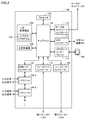
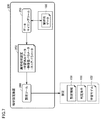
- FIG. 1 is a schematic diagram showing an overall configuration example of the abnormality detection system 1 according to the present embodiment.
- the abnormality detection system 1 can control the control target, and includes the control device 100 as a main component.
- the control device 100 executes a control calculation for controlling the control target, and also executes an abnormality detection process for detecting any abnormality that may occur in the monitoring target included in the control target.
- the control device 100 may be embodied as a kind of computer such as a PLC (programmable controller).
- the control device 100 is connected to the field device group 10 via the first field bus 2 and is connected to one or more display devices 400 via the second field bus 4. Further, the control device 100 can be connected to an external device such as the analysis setting device 200 via the local network 6 and the Internet 8. Further, the support device 300 may be directly connected to the control device 100. The control device 100 exchanges data with and from the connected device via each network.
- the display device 400 has an optional configuration.
- the first fieldbus 2 and the second fieldbus 4 it is preferable to adopt a network that performs constant cycle communication in which the arrival time of data is guaranteed.
- EtherCAT registered trademark
- networks that perform such constant-period communication.
- the control device 100 collects data (hereinafter, also referred to as “input value”) acquired by the field device group 10 and transferred to the control device 100.
- the control device 100 executes a control calculation and an abnormality detection process based on the collected input values and the like.
- the field device group 10 includes a device that collects a state value of a controlled object or a manufacturing device or a production line related to control (hereinafter, also collectively referred to as a “field”) as an input value.
- state value is a term including a value that can be observed by an arbitrary control target (including: monitoring target), and is, for example, a physical value that can be measured by an arbitrary sensor, a relay, a switch, or the like. It may include an ON / OFF state, a command value such as a position, speed, and torque given to the servo driver by the PLC, and a variable value used by the PLC for calculation.
- the field device group 10 further includes a device that gives some action to the field based on a command value (hereinafter, also referred to as “output value”) generated by the control device 100.
- a command value hereinafter, also referred to as “output value”
- an output relay, a contactor, a servo driver and a servo motor, and any other actuator are assumed.
- These field device groups 10 exchange data including input values and output values with and from the control device 100 via the first field bus 2.
- the field device group 10 includes a remote I / O (Input / Output) device 12, a relay group 14, an image sensor 18, a camera 20, a servo driver 22, and a servo motor 24. Including.
- the remote I / O device 12 includes a communication unit that communicates via the first fieldbus 2 and an input / output unit (hereinafter, also referred to as an “I / O unit”) for collecting input values and outputting output values. .) And. Input values and output values are exchanged between the control device 100 and the field via such an I / O unit.
- FIG. 1 shows an example in which digital signals are exchanged as input values and output values via the relay group 14.
- the I / O unit may be directly connected to the fieldbus.
- FIG. 1 shows an example in which the I / O unit 16 is directly connected to the first fieldbus 2.
- the image sensor 18 performs image measurement processing such as pattern matching on the image data captured by the camera 20, and transmits the processing result to the control device 100.
- the servo driver 22 drives the servomotor 24 according to an output value (for example, a position command) from the control device 100.
- the control device 100 includes an abnormality detection engine 130 in charge of the abnormality detection processing and an internal database for storing various data related to the abnormality detection processing (hereinafter, also referred to as “internal DB”). Including.) 140 and.
- the abnormality detection engine 130 determines whether or not any abnormality has occurred in the monitoring target included in the control target based on one or a plurality of state values collected from the control target.
- the analysis setting device 200 is basically arranged in a place different from the place where the abnormality detection system 1 is arranged.
- the analysis setting device 200 collects analysis data from the control device 100, and is used to make settings related to abnormality detection processing in the control device 100 based on the collected analysis data.
- the support device 300 supports the preparation necessary for the control calculation executed by the control device 100.
- the support device 300 includes a user program development environment (program creation / editing tool, parser, compiler, etc.) executed by the control device 100, setting parameters of the control device 100 and various devices connected to the control device 100. It provides a function for determining (configuration), a function for transmitting a generated user program to the control device 100, a function for modifying / changing a user program executed on the control device 100, and the like online.
- the display device 400 is connected to the control device 100 via the second fieldbus 4, receives an operation from the user, transmits a command or the like according to the user operation to the control device 100, and the control device 100. Graphically display the processing results of.
- the control device 100 executes a control operation for controlling the control target, and also executes an abnormality detection process for determining whether or not some abnormality has occurred in the monitoring target included in the control target ((1) control). Calculation and (2) anomaly detection).
- the control device 100 stores various information (analysis data) related to the abnormality detection process.
- the analysis setting device 200 collects analysis data stored in the control device 100 ((3) analysis data), and performs various analyzes based on the collected analysis data ((4) analysis). Typically, the analysis setup device 200 is expected to be operated by an expert with experience and expertise. The analysis setting device 200 determines the content of the setting related to the abnormality detection process of the control device 100 based on the results of various analyzes. Then, the analysis setting device 200 transmits the determined setting to the control device 100 ((5) setting). In the initial stage, the abnormality detection process may not be executed in the control device 100.
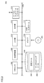
- FIG. 2 is a block diagram showing a hardware configuration example of the control device 100 constituting the abnormality detection system 1 according to the present embodiment.
- the control device 100 includes a processor 102 such as a CPU (Central Processing Unit) and an MPU (Micro-Processing Unit), a chip set 104, a main storage device 106, a secondary storage device 108, and the like.
- Local network controller 110 such as a CPU (Central Processing Unit) and an MPU (Micro-Processing Unit), a chip set 104, a main storage device 106, a secondary storage device 108, and the like.
- Local network controller 110 such as a CPU (Central Processing Unit) and an MPU (Micro-Processing Unit), a chip set 104, a main storage device 106, a secondary storage device 108, and the like.
- Local network controller 110 such as a CPU (Central Processing Unit) and an MPU (Micro-Processing Unit), a chip set 104, a main
- the processor 102 reads various programs stored in the secondary storage device 108, expands them in the main storage device 106, and executes them to realize control according to the control target and various processes as described later. ..
- the chipset 104 together with the processor 102, controls each component to realize the processing of the control device 100 as a whole.
- the user program executed by using the execution environment provided by the system program 126 is used. Is stored.
- the system program 126 also stores a program for realizing the abnormality detection engine 130 and the internal DB 140.
- the local network controller 110 controls the exchange of data with other devices via the local network 6.
- the USB controller 112 controls the exchange of data with the support device 300 via the USB connection.
- the memory card interface 114 is configured so that the memory card 116 can be attached and detached, data can be written to the memory card 116, and various data (user programs, trace data, etc.) can be read from the memory card 116. There is.
- the internal bus controller 122 is an interface for exchanging data with the I / O units 124-1, 124-2, ... Mounted on the control device 100.
- the fieldbus controller 118 controls the exchange of data with other devices via the first fieldbus 2.
- the fieldbus controller 120 controls the exchange of data with other devices via the second fieldbus 4.
- FIG. 2 shows a configuration example in which the necessary functions are provided by the processor 102 executing the program, and some or all of these provided functions are provided by a dedicated hardware circuit (for example, ASIC). It may be implemented using (Application Specific Integrated Circuit) or FPGA (Field-Programmable Gate Array). Alternatively, the main part of the control device 100 may be realized by using hardware that follows a general-purpose architecture (for example, an industrial personal computer based on a general-purpose personal computer). In this case, the virtualization technology may be used to execute a plurality of OSs (Operating Systems) having different uses in parallel, and to execute necessary applications on each OS.
- OSs Operating Systems
- the analysis setting device 200 is realized, for example, by executing a program using hardware (for example, a general-purpose personal computer) that follows a general-purpose architecture.
- hardware for example, a general-purpose personal computer
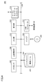
- FIG. 3 is a block diagram showing a hardware configuration example of the analysis setting device 200 constituting the abnormality detection system 1 according to the present embodiment.
- the analysis setting device 200 includes a processor 202 such as a CPU and an MPU, a drive 204, a main storage device 206, a secondary storage device 208, a USB controller 212, and a local network controller 214.
- the input unit 216 and the display unit 218 are included. These components are connected via bus 220.
- the processor 202 realizes various processes as described later by reading various programs stored in the secondary storage device 208, expanding them in the main storage device 206, and executing the programs.
- the secondary storage device 208 is composed of, for example, an HDD (Hard Disk Drive) or an SSD (Solid State Drive).
- the secondary storage device 208 typically stores various programs including a data mining tool 250 and a setting tool 260.
- the secondary storage device 208 may further store the OS and other necessary programs.
- the drive 204 can write data to the storage medium 205 and read various data (user program, trace data, time series data, etc.) from the storage medium 205.
- the storage medium 205 includes, for example, a storage medium 205 (for example, an optical storage medium such as a DVD (Digital Versatile Disc)) that temporarily stores a computer-readable program.
- the program or data stored in the storage medium 205 is read from the storage medium 205 and installed in an internal storage area such as the secondary storage device 208.
- the various programs executed by the analysis setting device 200 may be installed via a computer-readable storage medium 205, or may be installed by downloading from a server device or the like on the network. Further, the function provided by the analysis setting device 200 according to the present embodiment may be realized by using a part of the module provided by the OS.
- the USB controller 212 controls the exchange of data with other devices.
- the local network controller 214 controls the exchange of data with other devices via an arbitrary network.
- the input unit 216 is composed of a keyboard, a mouse, etc., and accepts user operations.
- the display unit 218 is composed of a display, various indicators, and the like, and outputs a processing result and the like from the processor 202.
- a printer may be connected to the analysis setting device 200.
- FIG. 3 shows a configuration example in which the necessary functions are provided by the processor 202 executing the program, and some or all of these provided functions are provided by a dedicated hardware circuit (for example, ASIC). Alternatively, it may be implemented using an FPGA or the like).
- a dedicated hardware circuit for example, ASIC
- FPGA field-programmable gate array
- the support device 300 is realized, for example, by executing a program using hardware (for example, a general-purpose personal computer) that follows a general-purpose architecture.
- hardware for example, a general-purpose personal computer
- FIG. 4 is a block diagram showing a hardware configuration example of the support device 300 constituting the abnormality detection system 1 according to the present embodiment.
- the support device 300 has the same hardware configuration as the analysis setting device 200.
- the support device 300 includes a processor 302 such as a CPU or MPU, a drive 304, a main storage device 306, a secondary storage device 308, a USB controller 312, a local network controller 314, and an input unit. 316 and a display unit 318 are included. These components are connected via the bus 320.
- a processor 302 such as a CPU or MPU
- a drive 304 a main storage device 306, a secondary storage device 308, a USB controller 312, a local network controller 314, and an input unit.
- 316 and a display unit 318 are included. These components are connected via the bus 320.
- the processor 302 realizes various processes as described later by reading various programs stored in the secondary storage device 308, deploying them in the main storage device 306, and executing the programs.
- the secondary storage device 308 is composed of, for example, an HDD or an SSD.
- the secondary storage device 308 typically includes a development tool 350 (not shown) for creating a user program executed by the control device 100, debugging the created program, defining a system configuration, setting various parameters, and the like. Is stored.
- the secondary storage device 308 may store the OS and other necessary programs.
- the drive 304 can write data to the storage medium 305 and read various data (user program, trace data, time series data, etc.) from the storage medium 305.
- the storage medium 305 includes, for example, a storage medium 305 (for example, an optical storage medium such as a DVD) that non-transiently stores a computer-readable program.
- the program or data stored in the storage medium 305 is read from the storage medium 305 and installed in an internal storage area such as the secondary storage device 308.
- Various programs executed by the support device 300 may be installed via a computer-readable storage medium 305, but may also be installed by downloading from a server device or the like on the network. Further, the function provided by the support device 300 according to the present embodiment may be realized by using a part of the module provided by the OS.
- the USB controller 312 controls the exchange of data with the control device 100 via the USB connection.
- the local network controller 314 controls the exchange of data with other devices via an arbitrary network.
- the input unit 316 is composed of a keyboard, a mouse, and the like, and accepts user operations.
- the display unit 318 is composed of a display, various indicators, and the like, and outputs a processing result and the like from the processor 302.
- a printer may be connected to the support device 300.
- FIG. 4 shows a configuration example in which the necessary functions are provided by the processor 302 executing the program, and some or all of these provided functions are provided by a dedicated hardware circuit (for example, ASIC). Alternatively, it may be implemented using an FPGA or the like).
- a dedicated hardware circuit for example, ASIC
- FPGA field-programmable gate array
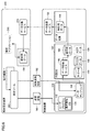
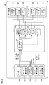
- FIG. 5 is a block diagram showing a configuration example for realizing the abnormality detection process executed by the abnormality detection system 1 according to the present embodiment.
- the control device 100 includes a variable management unit 160, a feature extraction unit 142, a machine learning processing unit 144, and a result determination unit 146 as a configuration related to the abnormality detection processing.
- the variable management unit 160 collects the state value (input value) appearing in the control target at each predetermined control cycle, and updates the value of the device variable 162 which is the internal state value.
- the present invention is not limited to the form of referencing a value using a "variable”, but can also be applied to a form of directly referencing a physical address of a memory for storing each value.
- the feature extraction unit 142 calculates one or more feature quantities 150 from one or more state values (input values) corresponding to the monitoring target. More specifically, the feature extraction unit 142 sets a value (or a temporal change of the value in a unit interval) indicated by one or a plurality of designated device variables 162 (state values) according to preset setting information 158. Based on the above, one or a plurality of feature quantities 150 (for example, average value, maximum value, minimum value, variance, etc. over frames) are calculated periodically or for each event according to a predetermined calculation procedure. As described above, the setting information 158 includes the designation of the state value to be collected and the designation of the feature amount calculated from the collected state value.
- the unit interval used by the feature extraction unit 142 to calculate the feature amount 150 may be referred to as a "frame".
- the “frame” means a unit interval for determining whether or not some abnormality has occurred in the monitored object. That is, it is determined for each "frame” whether or not any abnormality has occurred in the monitored object.
- the "frame” may be determined based on a state value arbitrarily set by the user.
- the machine learning processing unit 144 refers to the learning model 152, and is a value indicating that some abnormality may have occurred in the monitored target based on one or more feature quantities 150 calculated by the feature extraction unit 142. A certain score 154 is calculated.
- the machine learning processing unit 144 may adopt a method of calculating a score corresponding to the input value based on the degree of deviation of the input value with respect to the value group in the hyperspace as an abnormality detection algorithm.
- Anomaly detection methods based on the degree of deviation include a method of detecting anomalies based on the shortest distance from each point to a value group (k-nearest neighbor method), and a local outlier factor that evaluates the distance including the cluster including the value group. (LoF: local outlier factor) method, iForest (isolation forest) method using a score calculated from the path length, and the like are known.
- the learning model 152 When the learning model 152 is composed of normal features, it can be determined that the greater the degree of deviation from the learning model 152 (that is, the score), the higher the possibility that some abnormality has occurred in the monitored object. .. On the other hand, when the learning model 152 is composed of features at the time of abnormality, the smaller the degree of deviation from the learning model 152 (that is, the score), the higher the possibility that some abnormality has occurred in the monitored object. Can be judged.
- the learning model 152 can be determined by a known data mining method.
- the result determination unit 146 generates a determination result 170 indicating whether or not any abnormality has occurred in the monitoring target based on the score 154 calculated by the machine learning processing unit 144.
- the determination condition 156 includes a condition for determining whether or not it is abnormal, and may be preset by the support device 300. Typically, the determination condition 156 includes a threshold value or a threshold range set for the score 154, which indicates that there is a high possibility that some abnormality has occurred in the monitored object.
- the determination result 170 may be either "OK" in which no abnormality has occurred in the monitoring target or "NG" in which some abnormality has occurred in the monitoring target.
- the feature extraction unit 142, the machine learning processing unit 144, and the result determination unit 146 may be made into a library. In this case, by setting the setting information 158, the learning model 152, and the determination condition 156 in the library, even a user with little specialized knowledge can easily implement the abnormality detection process.
- the abnormality detection process according to the present embodiment has three phases of a data collection phase, a data analysis phase, and a data utilization phase. Each phase will be described below.
- the data collection phase is a phase for collecting data for making various settings related to the abnormality detection process. Although the data collection itself is executed by the control device 100, various settings related to the data collection and the use of the collected data are executed by the analysis setting device 200.
- FIG. 6 is a diagram for explaining the processing in the data collection phase in the abnormality detection system 1 according to the present embodiment.
- the user uses the setting tool 260 of the analysis setting device 200 to direct the variable definition 190 and the variable definition 190 to the control device 100 to be set.
- the collection variable designation 192 is created and transmitted to the control device 100 to be set.
- the variable definition 190 includes definitions such as a variable name for referring to a state value or an input value that can be collected by the control device 100.
- the collection variable designation 192 includes designation of a state value or an input value to be collected by the control device 100 in the data collection phase. In the collection variable specification 192, the state value or the input value to be collected may be specified by using the variable name defined in the variable definition 190 or the like.
- the control device 100 includes an abnormality detection engine 130 for realizing an abnormality detection process.
- the abnormality detection engine 130 is implemented as a process, and a user program 132 including an abnormality detection function block 134 (hereinafter, may be referred to as “abnormality detection FB”) is cyclically executed at predetermined control cycles.
- the abnormality detection function block 134 is an instruction block corresponding to the abnormality detection process. In this way, the control device 100 executes the user program 132 for controlling the controlled object.
- a specific example of the abnormality detection function block 134 will be described later.
- the abnormality detection process as shown in FIG. 5 is executed.
- the procedure of data sampling 136 is executed.
- the data sampling 136 collects one or more state values from the control target according to the designation (collection variable designation 192) from the analysis setting device 200.
- the procedure for data sampling 136 is typically enabled in the user program 132 by specifying specific parameters for the anomaly detection function block 134.
- the internal DB 140 can store raw data 180, filter data 182, and score data 184.
- the raw data 180, the filter data 182, and the score data 184 are all time series data.
- the raw data 180 is data in which the collected state values or the raw values of the input values are arranged in chronological order.
- the filter data 182 is data in which the results of filtering the raw data 180 according to the settings described later are arranged in chronological order.
- the score data 184 is data in which the scores calculated by the abnormality detection process are arranged in time series. In the collection phase, it is assumed that the abnormality detection process is not enabled, so that the score data 184 is often not generated.
- one or more scores can be calculated for each "frame" which is a unit interval.
- Information for defining such a frame may be included in the collection variable specification 192.
- one or more variable names that define the frame, and conditions for each variable (for example, either TRUE or FALSE) may be specified in the collection variable specification 192.
- a condition for defining a "subframe” in which the frame is subdivided may be included.
- an "event” may be defined as a condition for executing the abnormality detection process. In this case, the definition of "event” may be included in the collection variable specification 192.
- a frame, a subframe, the occurrence and end of an event, and the like may be determined according to an instruction included in the user program 132.
- the procedure of data sampling 136 requests the data storage service 148 included in the internal DB 140 to store the data (state value or input value) collected according to the collection variable specification 192.
- the data storage service 148 stores analysis data 186, which is data in which the values collected according to the collection variable designation 192 are arranged in chronological order in response to the request from the data sampling 136.
- the data storage service 148 generates all or a part of the stored analysis data 186 as analysis data 188 that can be referred to from an external device such as the analysis setting device 200.
- An external device such as the analysis setting device 200 can access the analysis data 188 via the data transmission service 138 of the control device 100.
- the data transmission service 138 of the control device 100 outputs (exports) the analysis data 188 to the analysis setting device 200. ..
- the analysis setting device 200 analyzes the analysis data 188 collected by the data collection service 270 using an arbitrary analysis application 280.
- the analysis application 280 may be an application dedicated to analysis or an arbitrary spreadsheet application.
- the user recreates or updates the variable definition 190 and the collected variable specification 192 by trial and error while referring to the analysis result obtained by using the analysis application 280. You may try to do it.
- the data collection phase as shown in FIG. 6 it is possible to find the optimum setting related to the abnormality detection process executed in the control device 100 to be set. Further, the user of the control device 100 (maintenance worker of the control device 100 or an operator of the equipment including the control device 100) can find the optimum setting of the abnormality detection process while limiting the disclosure of important information such as know-how as much as possible. Only the data necessary for the above can be disclosed to the outside.
- the data analysis phase is a phase in which the data collected in the data collection phase is analyzed to find the optimum setting related to the abnormality detection process.
- FIG. 7 is a diagram for explaining the processing in the data analysis phase in the abnormality detection system 1 according to the present embodiment.
- the user uses the data mining tool 250 of the analysis setting device 200 to collect analysis data 188 by the control device 100 to be set. Analyze (including one or more state values) and generate anomaly detection setting 252.
- the data mining tool 250 supports determination of the type of state value and feature amount (mean value, maximum value, minimum value, variance, etc.) suitable for abnormality detection processing.
- the abnormality detection setting 252 includes learned data, feature amount parameters, and score parameters.
- the trained data is data for constructing the learning model 152, and includes a feature amount calculated from raw data collected at the time of normal or abnormal.
- the feature amount parameter is a parameter that defines the feature amount to be calculated.
- the score parameter is a parameter that defines a calculation method of the score 154 (a value indicating the possibility that some abnormality has occurred in the monitored object).
- the setting tool 260 sets the operation of the abnormality detection engine 130 of the control device 100 based on the analysis result by the data mining tool 250 which is an analysis means. More specifically, the setting tool 260 sets the settings to be given to the control device 100 to be set based on the abnormality detection setting 252 generated by the data mining tool 250 (learning model 152, determination condition 156, setting information 158). To generate. This setting relates to the operation of the abnormality detection engine 130 of the control device 100.
- the setting tool 260 also functions as an interface with the control device 100, and can transmit the generated settings to the control device 100. Then, the abnormality detection engine 130 of the control device 100 receives the setting determined based on the result of the analysis setting device 200 analyzing the analysis data 188, and operates according to the setting.
- the data utilization phase is a phase in which the data obtained during the operation of the abnormality detection process in the control device 100 is utilized.
- FIG. 8 is a diagram for explaining the processing in the data utilization phase in the abnormality detection system 1 according to the present embodiment.
- the feature amount calculation process 133 for calculating the feature amount and the score calculation process 135 for calculating the score are cyclically executed for each control cycle.
- the data sampling 136 for collecting the state value or the input value and the data writing process 137 for writing the collected state value or the input value to the internal DB 140 are also cyclically executed. These processes are executed according to the value of the system-defined variable 128.
- Data sampling 136 generates each raw data for each cycle (control cycle).
- the feature amount calculation process 133 generates each feature amount for each frame.
- the score calculation process 135 generates each score for each frame.
- the data storage service 148 receives the raw data from the data sampling 136, the feature amount from the feature amount calculation process 133, and the score from the score calculation process 135, and receives the raw data 180, the filter data 182, the score data 184, and the analysis. Data 186 is generated.
- the internal DB 140 exposes all or part of the filter data 182, the score data 184, and the analysis data 186 so that they can be accessed externally.
- the publishing method may be selectable according to the setting for the control device 100.
- a publishing method for example, Web access (http-server), FTP access, storage media such as an SD card, and the like are assumed. Using these externally disclosed data, it is possible to examine the suitability and review of the abnormality detection process operated in the control device 100.
- the abnormality detection engine 130 collects data (filter data 182, score data 184,) in the process of determining whether or not any abnormality has occurred in the monitoring target included in the control target. (Analysis data 186, etc.) will be made publicly accessible to the outside.
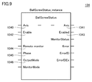
- FIG. 9 is a diagram showing an example of an abnormality detection function block 134 that can be described in a user program executed by the abnormality detection system 1 according to the present embodiment.
- the abnormality detection function block 134 shown in FIG. 9 is for detecting an abnormality that may occur in a device having a ball screw mechanism.
- the anomaly detection function block 134 includes an axis designation 1340, an activation flag 1342, an axis designation output 1341, and an activation flag output 1343 as inputs.
- a variable indicating an axis to be detected for abnormality is specified in the axis designation 1340, and a variable indicating a flag for enabling the abnormality detection process is specified in the activation flag 1342.
- the information of the variable specified in the axis designation 1340 is output from the axis designation output 1341, and the value of the flag specified in the activation flag 1342 is output from the activation flag output 1343.
- the abnormality detection function block 134 includes a remote monitor designation 1344, a phase designation 1345, and an output mode designation 1346 as inputs for realizing the processing corresponding to each of the above-mentioned phases. That is, the abnormality detection function block 134 includes a setting specified in the user program as an input.
- the remote monitor designation 1344 accepts the designation of whether or not to allow the mode change by the operation from the outside of the control device 100.
- TRUE is set in the remote monitor designation 1344
- the phase specified in the phase designation 1345 can be changed by an external operation.
- FALSE is set in the remote monitor designation 1344, the operation from the outside is prohibited.
- a restriction may be set when changing the value set in the remote monitor designation 1344 to TRUE.
- the operation of changing the remote monitor designation 1344 from TRUE to FALSE can be executed without limitation, whereas the operation of changing from FALSE to TRUE may be executed only by a user having a predetermined authority.
- Phase designation 1345 accepts phase designation for the target abnormality detection process. Specifically, one of the above-mentioned data collection phase, data analysis phase, and data utilization phase is designated in the phase designation 1345. However, in the data analysis phase, since the processing is executed by the analysis setting device 200, it is not necessary to execute the special processing in the control device 100. In this way, the operations of the abnormality detection engine 130, the data sampling 136, and the like are changed according to the settings such as the phase designation 1345 specified in the user program. That is, the data sampling 136 is in one or more states when the setting of the phase designation 1345 specified in the user program is a predetermined value (in this case, a value that specifies the "data collection phase"). Collect values.
- control device 100 collects the time series data of the designated variables according to the collection variable designation 192 transmitted from the analysis setting device 200, and generates the analysis data 188. (See FIG. 6).
- the control device 100 executes the abnormality detection process and makes all or part of the filter data 182, the score data 184, and the analysis data 186 accessible to the outside. It will be made public (see Fig. 8).
- the analysis data 186 includes a feature amount and a score calculated for each frame.
- the output mode designation 1346 accepts the designation of the output (publication) method of the generated data. Specifically, any one of Web access (http-server), FTP access, and SD card as described above is specified.
- the information for identifying the abnormality detection function block 134 for example, the function block name
- the information for identifying the abnormality detection function block 134 for example, the function block name
- a method of automatically transmitting data may be specified to a server prepared by the manufacturer of the control device 100 or the manufacturer of the device incorporating the control device 100.
- a method of transmitting data to a Web server prepared by the manufacturer http://client
- a method of transmitting data to an FTP server prepared by the manufacturer ftp client
- a method of transmitting data by e-mail The method of doing so is assumed.
- the data output (publication) destination may also be specifically specified.
- the input setting of the abnormality detection function block 134 can be arbitrarily changed by the user of the control device 100 (the maintenance worker of the control device 100 or the operator of the equipment including the control device 100) operating the support device 300. ing. Therefore, from the viewpoint of the user of the control device 100, only the abnormality detection processing that requires setting or adjustment can be selected and only the necessary data can be transmitted to an external expert, and the optimum abnormality detection can be performed while ensuring the security level. Processing can be realized.
- the history of operations from the outside may be stored in the control device 100 as a log.
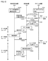
- FIG. 10 is a sequence diagram showing an example of a processing procedure in the abnormality detection system 1 according to the present embodiment.
- FIG. 10 shows a processing procedure including three phases, a data collection phase, a data analysis phase, and a data utilization phase.
- the user of the control device 100 operates the support device 300 to create a user program (sequence). SQ2).
- This user program includes an anomaly detection function block 134.
- the code of the abnormality detection function block 134 may be incorporated into the existing user program.
- the user of the control device 100 transmits the created user program to the control device 100 (sequence SQ4).
- control device 100 operates the support device 300 (sequence SQ6), sets “TRUE” of the remote monitor designation 1344 of the abnormality detection function block 134 included in the user program (sequence SQ8), and specifies the phase.
- a "data collection phase” is set in 1345 (sequence SQ10).
- the user of the analysis setting device 200 operates the analysis setting device 200 to determine the settings for data collection (variable definition 190 and collection variable designation 192). (Sequence SQ12). Then, the determined variable definition 190 and the collected variable designation 192 are transmitted to the control device 100 (sequence SQ14). Then, the control device 100 starts collecting the designated data (sequence SQ16).
- the analysis setting device 200 acquires the analysis data collected by the control device 100 (sequence SQ18).
- the user of the analysis setting device 200 performs an analysis operation using the acquired analysis data (sequence SQ20).
- the settings (setting information 158, learning model 152, and determination condition 156) determined by the analysis operation are transmitted from the analysis setting device 200 to the control device 100 (sequence SQ22).
- the control device 100 operates the support device 300 (sequence SQ24) and sets the "data utilization phase” in the phase designation 1345 of the abnormality detection function block 134 included in the user program (sequence SQ26). By this series of operations, the control device 100 starts the operation of the abnormality detection process.
- the control device 100 executes the abnormality detection process according to the setting from the analysis setting device 200 (sequence SQ28).
- the analysis data 186, the filter data 182, and the score data 184 generated by executing the abnormality detection process can be transmitted to the analysis setting device 200 (sequence SQ30).
- the user of the analysis setting device 200 examines the suitability and review of the abnormality detection process operated by the control device 100, if necessary.
- the optimum setting related to the abnormality detection process executed in the control device 100 can be determined.
- the abnormality detection system 1 may have an information management function.
- the information management function is a function capable of concealing a part of the information collected by the control device 100.
- the information management function for example, among the collected raw data, only the raw data of a specific section may be disclosed (the section to be disclosed is limited).
- the filter data 182 obtained by filtering the collected raw data may be disclosed.
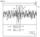
- FIG. 11 is a diagram for explaining an example of the information management function provided by the abnormality detection system 1 according to the present embodiment.
- the user interface screen 360 shown in FIG. 11 is typically provided by the support device 300.
- the user interface screen 360 may be displayed.
- the user interface screen 360 includes a time waveform 362 showing the raw data collected.
- the start position 364 and the end position 366 of the extraction section can be set for the time waveform 362.
- the user operates the pointer 368 to arrange the start position 364 and the end position 366 at arbitrary positions.
- the part where some abnormality has occurred can be set as the extraction section.
- the user of the control device 100 can operate the filter dialog 370 to select an arbitrary filter level (basically, a low-pass filter). Multiple filter levels may be selectable, depending on the particle size of the time. It is also possible to output the raw data as it is without applying a filter.
- the user of the control device 100 can operate the output destination dialog 372 to select an arbitrary output destination (publication destination). Then, when the output button 374 is selected, the data is output (published) to the selected output destination.
- control device 100 can disclose only the information explicitly permitted by the user among the one or more state values collected by data sampling to the outside accessible.
- the information disclosed to be externally accessible may include filter data 182 which is the result of filtering the time series data of one or a plurality of state values collected by data sampling.
- filter data 182 is the result of filtering the time series data of one or a plurality of state values collected by data sampling.
- the filter level may be automatically determined according to the publication destination.
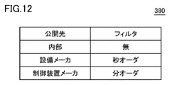
- FIG. 12 is a diagram for explaining an example of the filter level automatic selection function provided by the abnormality detection system 1 according to the present embodiment.
- the filter level 380 is defined to have different filter levels depending on the publication destination. For example, when outputting the information collected by the control device 100 to the manufacturer of the control device 100, the filter data 182 obtained by applying a "minute order" low-pass filter is output. On the other hand, raw data without filters will be output for internal disclosure.
- a control system (1) for controlling a controlled object Control device (100) and It is equipped with an analysis setting device (200) that can be connected to the control device.
- the control device Anomaly detection means (130) for determining whether or not any abnormality has occurred in the monitoring target included in the control target based on one or more state values collected from the control target, and A collection means (136) that collects one or more state values from the control target according to a designation from the analysis setting device.
- the analysis setting device is An analysis means (250) for acquiring and analyzing one or more state values collected by the control device, and A control system including a setting means (260) for setting an operation of the abnormality detecting means of the control device based on an analysis result by the analysis means.
- the control device is configured to execute a user program (132) for controlling the controlled object.
- the control system according to configuration 1 wherein the operation of the abnormality detecting means and the collecting means is changed according to a setting defined in the user program.
- the collecting means collects the one or a plurality of state values when the setting specified in the user program is a predetermined value.
- the user program includes an instruction block (134) corresponding to the anomaly detection means.
- the control system according to configuration 3, wherein the instruction block includes a setting (1344, 1345) specified in the user program as an input.
- the settings (152, 156, 158) related to the operation of the abnormality detecting means of the control device are the designation of the state value to be collected, the designation of the feature amount calculated from the collected state value, and whether the setting is abnormal.
- the control system according to any one of configurations 1 to 4, which includes a determination condition for determining whether or not the control system is used.
- the abnormality detecting means discloses the data (182, 184, 186) collected in the process of determining whether or not some abnormality has occurred in the monitoring target included in the control target so that it can be accessed externally.
- the control system according to any one of 5 to 5.
- the control device according to any one of configurations 1 to 6, wherein only the information explicitly permitted by the user among the one or a plurality of state values collected by the collecting means is disclosed to the outside accessible. Control system.
- the control system according to configuration 7, wherein the information disclosed to be externally accessible includes the result (182) of filtering the time series data of one or a plurality of state values collected by the collecting means.
- a control device (100) for controlling a controlled object Anomaly detection means (130) for determining whether or not any abnormality has occurred in the monitoring target included in the control target based on one or more state values collected from the control target, and It is provided with a collecting means (136) for collecting one or more state values from the controlled object according to a designation from an external device.
- the abnormality detecting means receives a setting (152,156,158) determined based on the result of analysis of one or a plurality of state values collected by the collecting means by an external device, and operates according to the setting. apparatus.
- a control program (126) executed by a control device (100) for controlling a controlled object, and the control program is applied to the control device.
- the determination step is a control program including a step (SQ22) that receives a setting determined based on the result of analysis of the collected one or more state values by an external device and operates according to the setting.
- the abnormality detection system even if the user of the control device does not have experience and expertise regarding the abnormality detection process, necessary data is transmitted to the analysis setting device, and the experience and An expert with specialized knowledge can analyze the transmitted data and make appropriate settings for the control device. Therefore, it is possible to easily implement the necessary abnormality detection process according to the control device or the control target. In addition, an expert who has experience and specialized knowledge can analyze the data transmitted from the control device without going to the site where the control device is installed, so that the work efficiency can be improved.
- 1 Abnormality detection system 2 1st field bus, 4 2nd field bus, 6 local network, 8 Internet, 10 field device group, 12 remote I / O device, 14 relay group, 16,124 I / O unit, 18 image Sensor, 20 camera, 22 servo driver, 24 servo motor, 100 control device, 102, 202, 302 processor, 104 chipset, 106, 206, 306 main storage device, 108, 208, 308 secondary storage device, 110, 214 , 314 local network controller, 112,212,312 USB controller, 114 memory card interface, 116 memory card, 118,120 field bus controller, 122 internal bus controller, 126 system program, 128 system definition variable, 130 abnormality detection engine, 132 User program, 133 feature amount calculation process, 134 abnormality detection function block, 135 score calculation process, 136 data sampling, 137 data writing process, 138 data transmission service, 140 internal DB, 142 feature extraction unit, 144 machine learning processing unit, 146 result judgment unit, 148 data storage service, 150 feature amount,
Landscapes
- Physics & Mathematics (AREA)
- General Physics & Mathematics (AREA)
- Engineering & Computer Science (AREA)
- Automation & Control Theory (AREA)
- Programmable Controllers (AREA)
- Testing And Monitoring For Control Systems (AREA)
Abstract
制御対象を制御するための制御システムは、制御装置と、制御装置に接続可能な解析設定装置とを含む。制御装置は、制御対象から収集される1または複数の状態値に基づいて、制御対象に含まれる監視対象に何らかの異常が発生しているか否かを判定する異常検知手段と、解析設定装置からの指定に従って、制御対象から1または複数の状態値を収集する収集手段とを含む。解析設定装置は、制御装置により収集された1または複数の状態値を取得して解析する解析手段と、解析手段による解析結果に基づいて、制御装置の異常検知手段の動作を設定する設定手段とを含む。
Description
本発明は、監視対象に発生し得る何らかの異常を検知可能な制御システム、ならびに、その制御システムを構成する制御装置およびその制御プログラムに関する。
様々な生産現場において、機械や装置に対する予知保全により設備稼働率を向上させたいというニーズが存在する。予知保全とは、機械や装置に生じる何らかの異常を検知して、設備を停止しなければ状態になる前に、整備や交換などの保守作業を行うような保全形態を意味する。
予知保全を実現するために、機械や装置の状態値を収集するとともに、収集された状態値に基づいて、当該機械や装置に何らかの異常が生じているか否かを判定するような仕組みが必要となる。例えば、特開2018-097662号公報(特許文献1)は、制御対象に生じている現象をより短い周期で監視できる技術を開示する。
制御対象は多数の情報を有しており、異常検知を行うためにどのような情報を用いるべきかといった設定には、経験および専門知識などが必要になる。様々な生産現場に異常検知の導入および運用するにあたっては、このような経験および専門知識を容易に活用できるような仕組みが必要となる。
本発明の一つの目的は、異常検知の導入および運用を容易化するための仕組みを提供することである。
本発明の一例によれば、制御対象を制御するための制御システムが提供される。制御システムは、制御装置と、制御装置に接続可能な解析設定装置とを含む。制御装置は、制御対象から収集される1または複数の状態値に基づいて、制御対象に含まれる監視対象に何らかの異常が発生しているか否かを判定する異常検知手段と、解析設定装置からの指定に従って、制御対象から1または複数の状態値を収集する収集手段とを含む。解析設定装置は、制御装置により収集された1または複数の状態値を取得して解析する解析手段と、解析手段による解析結果に基づいて、制御装置の異常検知手段の動作を設定する設定手段とを含む。
この構成によれば、制御装置のユーザが経験および専門知識などを有していない場合であっても、異常検知処理の動作を適切に設定することができ、要求に応じた異常検知処理を運用できる。
制御装置は、制御対象を制御するためのユーザプログラムを実行するように構成されていてもよい。異常検知手段および収集手段は、ユーザプログラムに規定される設定に応じて動作が変更されてもよい。この構成によれば、制御装置のユーザは、ユーザプログラムを変更することで、異常検知手段および収集手段の挙動を任意に制御できる。
収集手段は、ユーザプログラムに規定される設定が予め定められた値である場合において、1または複数の状態値を収集してもよい。この構成によれば、ユーザプログラムの内用を制御することで、データ収集を特定の期間に限定できるので、セキュリティレベルを担保できる。
ユーザプログラムは、異常検知手段に対応する命令ブロックを含んでいてもよい。命令ブロックは、入力として、ユーザプログラムに規定される設定を含んでいてもよい。この構成によれば、制御装置のユーザは、ユーザプログラム内に複数の命令を記述することなく、特定の命令ブロックのみを記述すれば済むので、作業量などを低減できる。
制御装置の異常検知手段の動作に係る設定は、収集すべき状態値の指定と、収集された状態値から算出される特徴量の指定と、異常であるか否かを判定するための判定条件とを含んでいてもよい。この構成によれば、制御装置で実行される異常検知処理の挙動を詳細に制御できる。
異常検知手段は、制御対象に含まれる監視対象に何らかの異常が発生しているか否かを判定する処理において収集されたデータを外部アクセス可能に公開してもよい。この構成によれば、異常検知処理の運用中に得られたデータに基づいて、運用中の異常検知処理の見直しなどを容易に行うことができる。
制御装置は、収集手段が収集した1または複数の状態値のうち、ユーザから明示的に許可された情報のみを外部アクセス可能に公開してもよい。この構成によれば、営業秘密やノウハウなどを含み得る情報の公開を任意に制限できる。
外部アクセス可能に公開される情報は、収集手段が収集した1または複数の状態値の時系列データをフィルタリングした結果を含んでいてもよい。この構成によれば、そのまま外部に公開することが好ましくない情報が含まれる場合であっても、異常検知処理を適切に設定できる。
本発明の別の一例によれば、制御対象を制御するための制御装置が提供される。制御装置は、制御対象から収集される1または複数の状態値に基づいて、制御対象に含まれる監視対象に何らかの異常が発生しているか否かを判定する異常検知手段と、外部装置からの指定に従って、制御対象から1または複数の状態値を収集する収集手段とを含む。異常検知手段は、収集手段が収集した1または複数の状態値を外部装置が解析した結果に基づいて決定された設定を受けて、当該設定に従って動作する。
この構成によれば、制御装置のユーザが経験および専門知識などを有していない場合であっても、異常検知処理の動作を適切に設定することができ、要求に応じた異常検知処理を運用できる。
本発明のさらに別の一例によれば、制御対象を制御するための制御装置で実行される制御プログラムが提供される。制御プログラムは、制御装置に、制御対象から収集される1または複数の状態値に基づいて、制御対象に含まれる監視対象に何らかの異常が発生しているか否かを判定するステップと、外部装置からの指定に従って、制御対象から1または複数の状態値を収集するステップとを実行させる。判定するステップは、収集された1または複数の状態値を外部装置が解析した結果に基づいて決定された設定を受けて、当該設定に従って動作するステップを含む。
この構成によれば、制御装置のユーザが経験および専門知識などを有していない場合であっても、異常検知処理の動作を適切に設定することができ、要求に応じた異常検知処理を運用できる。
本発明によれば、異常検知の導入および運用を容易化するための仕組みを提供できる。
本発明の実施の形態について、図面を参照しながら詳細に説明する。なお、図中の同一または相当部分については、同一符号を付してその説明は繰り返さない。
<A.適用例>
まず、本発明が適用される場面の一例について説明する。
まず、本発明が適用される場面の一例について説明する。
本実施の形態に従う異常検知処理を実行可能な制御システムの機能的な構成例について説明する。以下の説明においては、主として、制御システムが有している異常検知処理に注目して説明するので、制御システム全体を「異常検知システム」とも称する。
まず、本実施の形態に従う異常検知システム1の全体構成例について説明する。
図1は、本実施の形態に従う異常検知システム1の全体構成例を示す模式図である。図1を参照して、異常検知システム1は、制御対象を制御することができ、主たる構成要素として、制御装置100を含む。
図1は、本実施の形態に従う異常検知システム1の全体構成例を示す模式図である。図1を参照して、異常検知システム1は、制御対象を制御することができ、主たる構成要素として、制御装置100を含む。
制御装置100は、制御対象に対する制御を行うための制御演算を実行するとともに、制御対象に含まれる監視対象に生じ得る何らかの異常を検知するための異常検知処理を実行する。制御装置100は、PLC(プログラマブルコントローラ)などの、一種のコンピュータとして具現化されてもよい。
制御装置100は、第1フィールドバス2を介してフィールド装置群10と接続されるとともに、第2フィールドバス4を介して1または複数の表示装置400と接続される。さらに、制御装置100は、ローカルネットワーク6およびインターネット8を介して、解析設定装置200などの外部装置にも接続可能になっている。また、制御装置100には、サポート装置300が直接的に接続されることもある。制御装置100は、それぞれのネットワークを介して、接続された装置との間でデータを遣り取りする。なお、表示装置400は、オプショナルな構成である。
第1フィールドバス2および第2フィールドバス4としては、データの到達時間が保証される、定周期通信を行うネットワークを採用することが好ましい。このような定周期通信を行うネットワークとしては、EtherCAT(登録商標)などが知られている。
制御装置100は、フィールド装置群10にて取得され、制御装置100へ転送されるデータ(以下、「入力値」とも称す。)を収集する。制御装置100は、収集した入力値などに基づいて、制御演算および異常検知処理を実行する。
フィールド装置群10は、制御対象または制御に関連する製造装置や生産ラインなど(以下、「フィールド」とも総称する。)の状態値を入力値として収集する装置を含む。
本明細書において、「状態値」は、任意の制御対象(含む:監視対象)にて観測できる値を包含する用語であり、例えば、任意のセンサにより測定できる物理値や、リレーやスイッチなどのON/OFF状態、PLCがサーボドライバに与える位置、速度、トルクなどの指令値、PLCが演算に用いる変数値などを含み得る。
このような状態値を収集する装置としては、入力リレーや各種センサなどが想定される。フィールド装置群10は、さらに、制御装置100にて生成される指令値(以下、「出力値」とも称す。)に基づいて、フィールドに対して何らかの作用を与える装置を含む。このようなフィールドに対して何らかの作用を与える装置としては、出力リレー、コンタクタ、サーボドライバおよびサーボモータ、その他任意のアクチュエータが想定される。これらのフィールド装置群10は、第1フィールドバス2を介して、制御装置100との間で、入力値および出力値を含むデータを遣り取りする。
図1に示す構成例においては、フィールド装置群10は、リモートI/O(Input/Output)装置12と、リレー群14と、画像センサ18およびカメラ20と、サーボドライバ22およびサーボモータ24とを含む。
リモートI/O装置12は、第1フィールドバス2を介して通信を行う通信部と、入力値の収集および出力値の出力を行うための入出力部(以下、「I/Oユニット」とも称す。)とを含む。このようなI/Oユニットを介して、制御装置100とフィールドとの間で入力値および出力値が遣り取りされる。図1には、リレー群14を介して、入力値および出力値として、デジタル信号が遣り取りされる例が示されている。
I/Oユニットは、フィールドバスに直接接続されるようにしてもよい。図1には、第1フィールドバス2にI/Oユニット16が直接接続されている例を示す。
画像センサ18は、カメラ20によって撮像された画像データに対して、パターンマッチングなどの画像計測処理を行って、その処理結果を制御装置100へ送信する。
サーボドライバ22は、制御装置100からの出力値(例えば、位置指令など)に従って、サーボモータ24を駆動する。
本実施の形態に従う異常検知処理に関して、制御装置100は、異常検知処理を担当する異常検知エンジン130、および、異常検知処理に係る各種データを格納するための内部データベース(以下、「内部DB」とも記す。)140とを含む。異常検知エンジン130は、制御対象から収集される1または複数の状態値に基づいて、制御対象に含まれる監視対象に何らかの異常が発生しているか否かを判定する。
解析設定装置200は、基本的には、異常検知システム1が配置される場所とは異なる場所に配置されることが想定されている。解析設定装置200は、制御装置100から解析用データを収集し、収集した解析用データに基づいて、制御装置100における異常検知処理に係る設定を行うために用いられる。
サポート装置300は、制御装置100で実行される制御演算に必要な準備を支援する。具体的には、サポート装置300は、制御装置100で実行されるユーザプログラムの開発環境(プログラム作成編集ツール、パーサ、コンパイラなど)、制御装置100および制御装置100に接続される各種デバイスの設定パラメータ(コンフィギュレーション)を決定するための機能、生成したユーザプログラムを制御装置100へ送信する機能、制御装置100上で実行されるユーザプログラムなどをオンラインで修正・変更する機能、などを提供する。
表示装置400は、第2フィールドバス4を介して制御装置100と接続され、ユーザからの操作を受けて、制御装置100に対してユーザ操作に応じたコマンドなどを送信するとともに、制御装置100での処理結果などをグラフィカルに表示する。
図1を参照して、本実施の形態に従う異常検知システム1が提供する機能の一例について概説する。
制御装置100は、制御対象を制御するための制御演算を実行するとともに、制御対象に含まれる監視対象に何らかの異常が発生しているか否かを判断する異常検知処理を実行する((1)制御演算および(2)異常検知)。制御装置100は、異常検知処理に関連する各種情報(解析用データ)を格納する。
解析設定装置200は、制御装置100に格納されている解析用データを収集し((3)解析用データ)、収集した解析用データに基づいて各種解析を行う((4)解析)。典型的には、解析設定装置200は、経験および専門知識を有している専門家が操作することが想定されている。解析設定装置200は、各種解析の結果に基づいて、制御装置100の異常検知処理に係る設定の内容を決定する。そして、解析設定装置200は、決定した設定を制御装置100へ送信する((5)設定)。なお、初期段階では、制御装置100において異常検知処理が実行されてなくてもよい。
このような処理サイクルを繰り返すことによって、制御装置100に対して、要求および目的に適した異常検知処理を実装することができる。
<B.各装置のハードウェア構成例>
次に、本実施の形態に従う異常検知システム1を構成する主要な装置のハードウェア構成例について説明する。
次に、本実施の形態に従う異常検知システム1を構成する主要な装置のハードウェア構成例について説明する。
(b1:制御装置100のハードウェア構成例)
図2は、本実施の形態に従う異常検知システム1を構成する制御装置100のハードウェア構成例を示すブロック図である。図2を参照して、制御装置100は、CPU(Central Processing Unit)やMPU(Micro-Processing Unit)などのプロセッサ102と、チップセット104と、主記憶装置106と、二次記憶装置108と、ローカルネットワークコントローラ110と、USB(Universal Serial Bus)コントローラ112と、メモリカードインターフェイス114と、内部バスコントローラ122と、フィールドバスコントローラ118,120と、I/Oユニット124-1,124-2,…とを含む。
図2は、本実施の形態に従う異常検知システム1を構成する制御装置100のハードウェア構成例を示すブロック図である。図2を参照して、制御装置100は、CPU(Central Processing Unit)やMPU(Micro-Processing Unit)などのプロセッサ102と、チップセット104と、主記憶装置106と、二次記憶装置108と、ローカルネットワークコントローラ110と、USB(Universal Serial Bus)コントローラ112と、メモリカードインターフェイス114と、内部バスコントローラ122と、フィールドバスコントローラ118,120と、I/Oユニット124-1,124-2,…とを含む。
プロセッサ102は、二次記憶装置108に格納された各種プログラムを読み出して、主記憶装置106に展開して実行することで、制御対象に応じた制御、および、後述するような各種処理を実現する。チップセット104は、プロセッサ102とともに、各コンポーネントを制御することで、制御装置100全体としての処理を実現する。
二次記憶装置108には、制御装置100が提供する機能を実現するためのシステムプログラム126(制御プログラムに相当)に加えて、システムプログラム126が提供する実行環境を利用して実行されるユーザプログラムが格納される。システムプログラム126は、異常検知エンジン130および内部DB140を実現するためのプログラムも格納される。
ローカルネットワークコントローラ110は、ローカルネットワーク6を介した他の装置との間のデータの遣り取りを制御する。USBコントローラ112は、USB接続を介してサポート装置300との間のデータの遣り取りを制御する。
メモリカードインターフェイス114は、メモリカード116を着脱可能に構成されており、メモリカード116に対してデータを書き込み、メモリカード116から各種データ(ユーザプログラムやトレースデータなど)を読み出すことが可能になっている。
内部バスコントローラ122は、制御装置100に搭載されるI/Oユニット124-1,124-2,…との間でデータを遣り取りするインターフェイスである。
フィールドバスコントローラ118は、第1フィールドバス2を介した他の装置との間のデータの遣り取りを制御する。同様に、フィールドバスコントローラ120は、第2フィールドバス4を介した他の装置との間のデータの遣り取りを制御する。
図2には、プロセッサ102がプログラムを実行することで必要な機能が提供される構成例を示したが、これらの提供される機能の一部または全部を、専用のハードウェア回路(例えば、ASIC(Application Specific Integrated Circuit)またはFPGA(Field-Programmable Gate Array)など)を用いて実装してもよい。あるいは、制御装置100の主要部を、汎用的なアーキテクチャに従うハードウェア(例えば、汎用パソコンをベースとした産業用パソコン)を用いて実現してもよい。この場合には、仮想化技術を用いて、用途の異なる複数のOS(Operating System)を並列的に実行させるとともに、各OS上で必要なアプリケーションを実行させるようにしてもよい。
(b2:解析設定装置200のハードウェア構成例)
本実施の形態に従う解析設定装置200は、一例として、汎用的なアーキテクチャに従うハードウェア(例えば、汎用パソコン)を用いてプログラムを実行することで実現される。
本実施の形態に従う解析設定装置200は、一例として、汎用的なアーキテクチャに従うハードウェア(例えば、汎用パソコン)を用いてプログラムを実行することで実現される。
図3は、本実施の形態に従う異常検知システム1を構成する解析設定装置200のハードウェア構成例を示すブロック図である。図3を参照して、解析設定装置200は、CPUやMPUなどのプロセッサ202と、ドライブ204と、主記憶装置206と、二次記憶装置208と、USBコントローラ212と、ローカルネットワークコントローラ214と、入力部216と、表示部218とを含む。これらのコンポーネントはバス220を介して接続される。
プロセッサ202は、二次記憶装置208に格納された各種プログラムを読み出して、主記憶装置206に展開して実行することで、後述するような各種処理を実現する。
二次記憶装置208は、例えば、HDD(Hard Disk Drive)やSSD(Solid State Drive)などで構成される。二次記憶装置208には、典型的には、データマイニングツール250と、設定ツール260とを含む各種プログラムが格納される。二次記憶装置208には、OSおよび他の必要なプログラムがさらに格納されていてもよい。
ドライブ204は、記憶媒体205に対してデータを書き込み、記憶媒体205から各種データ(ユーザプログラム、トレースデータまたは時系列データなど)を読み出すことが可能になっている。記憶媒体205は、例えばコンピュータ読取可能なプログラムを非一過的に格納する記憶媒体205(例えば、DVD(Digital Versatile Disc)などの光学記憶媒体)を含む。記憶媒体205から、その中に格納されたプログラムまたはデータが読み取られて二次記憶装置208などの内部の記憶領域にインストールされる。
解析設定装置200で実行される各種プログラムは、コンピュータ読取可能な記憶媒体205を介してインストールされてもよいが、ネットワーク上のサーバ装置などからダウンロードする形でインストールするようにしてもよい。また、本実施の形態に従う解析設定装置200が提供する機能は、OSが提供するモジュールの一部を利用する形で実現される場合もある。
USBコントローラ212は、他の装置との間のデータの遣り取りを制御する。ローカルネットワークコントローラ214は、任意ネットワークを介した他の装置との間のデータの遣り取りを制御する。
入力部216は、キーボードやマウスなどで構成され、ユーザ操作を受け付ける。表示部218は、ディスプレイ、各種インジケータなどで構成され、プロセッサ202からの処理結果などを出力する。解析設定装置200には、プリンタが接続されてもよい。
図3には、プロセッサ202がプログラムを実行することで必要な機能が提供される構成例を示したが、これらの提供される機能の一部または全部を、専用のハードウェア回路(例えば、ASICまたはFPGAなど)を用いて実装してもよい。
(b3:サポート装置300のハードウェア構成例)
本実施の形態に従うサポート装置300は、一例として、汎用的なアーキテクチャに従うハードウェア(例えば、汎用パソコン)を用いてプログラムを実行することで実現される。
本実施の形態に従うサポート装置300は、一例として、汎用的なアーキテクチャに従うハードウェア(例えば、汎用パソコン)を用いてプログラムを実行することで実現される。
図4は、本実施の形態に従う異常検知システム1を構成するサポート装置300のハードウェア構成例を示すブロック図である。図4を参照して、サポート装置300は、解析設定装置200と同様のハードウェア構成を有している。
より具体的には、サポート装置300は、CPUやMPUなどのプロセッサ302と、ドライブ304と、主記憶装置306と、二次記憶装置308と、USBコントローラ312と、ローカルネットワークコントローラ314と、入力部316と、表示部318とを含む。これらのコンポーネントはバス320を介して接続される。
プロセッサ302は、二次記憶装置308に格納された各種プログラムを読み出して、主記憶装置306に展開して実行することで、後述するような各種処理を実現する。
二次記憶装置308は、例えば、HDDやSSDなどで構成される。二次記憶装置308には、典型的には、制御装置100において実行されるユーザプログラムの作成、作成したプログラムのデバッグ、システム構成の定義、各種パラメータの設定などを行うための図示しない開発ツール350が格納される。二次記憶装置308には、OSおよび他の必要なプログラムが格納されていてもよい。
ドライブ304は、記憶媒体305に対してデータを書き込み、記憶媒体305から各種データ(ユーザプログラム、トレースデータまたは時系列データなど)を読み出すことが可能になっている。記憶媒体305は、例えばコンピュータ読取可能なプログラムを非一過的に格納する記憶媒体305(例えば、DVDなどの光学記憶媒体)を含む。記憶媒体305から、その中に格納されたプログラムまたはデータが読み取られて二次記憶装置308などの内部の記憶領域にインストールされる。
サポート装置300で実行される各種プログラムは、コンピュータ読取可能な記憶媒体305を介してインストールされてもよいが、ネットワーク上のサーバ装置などからダウンロードする形でインストールするようにしてもよい。また、本実施の形態に従うサポート装置300が提供する機能は、OSが提供するモジュールの一部を利用する形で実現される場合もある。
USBコントローラ312は、USB接続を介して制御装置100との間のデータの遣り取りを制御する。ローカルネットワークコントローラ314は、任意ネットワークを介した他の装置との間のデータの遣り取りを制御する。
入力部316は、キーボードやマウスなどで構成され、ユーザ操作を受け付ける。表示部318は、ディスプレイ、各種インジケータなどで構成され、プロセッサ302からの処理結果などを出力する。サポート装置300には、プリンタが接続されてもよい。
図4には、プロセッサ302がプログラムを実行することで必要な機能が提供される構成例を示したが、これらの提供される機能の一部または全部を、専用のハードウェア回路(例えば、ASICまたはFPGAなど)を用いて実装してもよい。
<C.異常検知処理>
次に、本実施の形態に従う異常検知システム1で実行される異常検知処理について説明する。
次に、本実施の形態に従う異常検知システム1で実行される異常検知処理について説明する。
図5は、本実施の形態に従う異常検知システム1で実行される異常検知処理を実現するための構成例を示すブロック図である。図5を参照して、制御装置100は、異常検知処理に係る構成として、変数管理部160と、特徴抽出部142と、機械学習処理部144と、結果判定部146とを含む。
変数管理部160は、制御対象に現れる状態値(入力値)を予め定められた制御周期毎に収集して、内部状態値であるデバイス変数162の値を更新する。なお、本発明は「変数」を用いて値を参照する形態に限られることなく、各値を格納するメモリの物理アドレスなどを直接参照する形態などにも適用可能である。
特徴抽出部142は、監視対象に対応する1または複数の状態値(入力値)から1または複数の特徴量150を算出する。より具体的には、特徴抽出部142は、予め設定された設定情報158に従って、指定された1または複数のデバイス変数162(状態値)が示す値(あるいは、単位区間における値の時間的変化)に基づいて、予め定められた算出手順に従って1または複数の特徴量150(例えば、フレームに亘る平均値、最大値、最小値、分散など)を周期的またはイベント毎に算出する。このように、設定情報158は、収集すべき状態値の指定と、収集された状態値から算出される特徴量の指定とを含む。
特徴抽出部142が特徴量150を算出するために用いる単位区間を「フレーム」と称することもある。本明細書において、「フレーム」は、監視対象に何らかの異常が発生しているか否かを判定する単位区間を意味する。すなわち、監視対象に何らかの異常が発生しているか否かの判定は、「フレーム」毎に行われることになる。本実施の形態においては、「フレーム」は、ユーザが任意に設定する状態値に基づいて決定されるようにしてもよい。
機械学習処理部144は、学習モデル152を参照して、特徴抽出部142により算出される1または複数の特徴量150に基づいて、監視対象に何らかの異常が発生している可能性を示す値であるスコア154を算出する。
一例として、機械学習処理部144は、異常検知のアルゴリズムとして、超空間上における値群に対する入力値の外れ度合いに基づいて、当該入力値に対応するスコアを算出する方法を採用してもよい。外れ度合いに基づく異常検知の手法としては、各点から値群までの最短距離に基づいて異常を検知する手法(k近傍法)、値群を含むクラスタを含めて距離を評価する局所外れ値因子(LoF:local outlier factor)法、パス長さから算出されるスコアを用いるiForest(isolation forest)法などが知られている。
学習モデル152が正常時の特徴量から構成される場合には、学習モデル152からの外れ度合い(すなわち、スコア)が大きいほど、監視対象に何らかの異常が発生している可能性が高いと判定できる。一方、学習モデル152が異常時の特徴量から構成される場合には、学習モデル152からの外れ度合い(すなわち、スコア)が小さいほど、監視対象に何らかの異常が発生している可能性が高いと判定できる。学習モデル152は、公知のデータマイニングの手法により決定することができる。
結果判定部146は、機械学習処理部144により算出されるスコア154に基づいて、監視対象に何らかの異常が発生しているか否かを示す判定結果170を生成する。判定条件156は、異常であるか否かを判定するための条件を含み、サポート装置300により予め設定されてもよい。典型的には、判定条件156は、スコア154に対して設定される、監視対象に何らかの異常が発生している可能性が高いことを示す、しきい値またはしきい範囲などを含む。判定結果170は、監視対象に何らの異常も発生していない状態である「OK」、および、監視対象に何らかの異常が発生している状態である「NG」のいずれかであってもよい。
以上のような構成を採用することで、制御対象に含まれる任意の監視対象について、発生し得る何らかの異常の発生を検知できる。なお、特徴抽出部142、機械学習処理部144および結果判定部146をライブラリ化してもよい。この場合には、設定情報158、学習モデル152および判定条件156をライブラリに設定することで、専門知識の乏しいユーザであっても、異常検知処理を容易に実装できる。
<D.異常検知処理に係る処理>
本実施の形態に従う異常検知処理は、データ収集フェーズ、データ解析フェーズ、データ活用フェーズの3つのフェーズを有している。以下、各フェーズについて説明する。
本実施の形態に従う異常検知処理は、データ収集フェーズ、データ解析フェーズ、データ活用フェーズの3つのフェーズを有している。以下、各フェーズについて説明する。
(d1:データ収集フェーズ)
データ収集フェーズは、異常検知処理に係る各種設定を行うためのデータを収集するフェーズである。データの収集自体は、制御装置100において実行されるものの、データの収集に係る各種設定、および、収集されたデータの利用は、解析設定装置200において実行される。
データ収集フェーズは、異常検知処理に係る各種設定を行うためのデータを収集するフェーズである。データの収集自体は、制御装置100において実行されるものの、データの収集に係る各種設定、および、収集されたデータの利用は、解析設定装置200において実行される。
図6は、本実施の形態に従う異常検知システム1におけるデータ収集フェーズでの処理を説明するための図である。図6を参照して、ユーザ(経験および専門知識を有している専門家)は、解析設定装置200の設定ツール260を用いて、設定対象の制御装置100に向けられた、変数定義190および収集変数指定192を作成し、設定対象の制御装置100に送信する。
変数定義190は、制御装置100が収集可能な状態値あるいは入力値を参照するための変数名などの定義を含む。収集変数指定192は、データ収集フェーズにおいて制御装置100にて収集される対象となる状態値あるいは入力値の指定を含む。収集変数指定192では、収集対象となる状態値あるいは入力値は、変数定義190において定義された変数名などを用いて特定されてもよい。
制御装置100は、異常検知処理を実現するための異常検知エンジン130を含む。異常検知エンジン130は、プロセスとして実装され、異常検知ファンクションブロック134(以下、「異常検知FB」と記載する場合もある。)を含むユーザプログラム132が予め定められた制御周期毎にサイクリック実行される。異常検知ファンクションブロック134は、異常検知処理に対応する命令ブロックである。このように、制御装置100は、制御対象を制御するためのユーザプログラム132を実行する。異常検知ファンクションブロック134の具体例については後述する。
異常検知ファンクションブロック134が実行されることで、図5に示すような異常検知処理が実行される。併せて、データサンプリング136のプロシージャが実行される。データサンプリング136は、解析設定装置200からの指定(収集変数指定192)に従って、制御対象から1または複数の状態値を収集する。データサンプリング136のプロシージャは、典型的には、ユーザプログラム132において、異常検知ファンクションブロック134に対して特定のパラメータを指定することで、有効化される。
内部DB140は、生データ180と、フィルタデータ182と、スコアデータ184とを格納可能になっている。生データ180と、フィルタデータ182と、スコアデータ184とは、いずれも時系列データである。生データ180は、収集された状態値または入力値のそのままの値が時系列に並べられたデータである。フィルタデータ182は、後述するような設定に従って、生データ180をフィルタリングした結果が時系列に並べられたデータである。スコアデータ184は、異常検知処理によって算出されたスコアが時系列に並べられたデータである。収集フェーズにおいては、異常検知処理が有効化されていないことが想定されているので、スコアデータ184は生成されない場合も多い。
なお、本実施の形態に従う異常検知処理においては、単位区間である「フレーム」毎に1または複数のスコアを算出することができる。このようなフレームを規定するための情報を収集変数指定192に含めるようにしてもよい。具体的には、フレームを規定する1または複数の変数名、および、各変数についての条件(例えば、TRUEおよびFALSEのいずれか)を収集変数指定192に規定してもよい。また、フレームを細分化した「サブフレーム」を規定するための条件を含めるようにしてもよい。さらに、異常検知処理を実行するための条件として「イベント」を規定してもよい。この場合には、「イベント」の定義を収集変数指定192に含めてもよい。上述したような、フレーム、サブフレーム、イベントの発生および終了などは、ユーザプログラム132に含まれる命令に従って判定されてもよい。
データサンプリング136のプロシージャは、内部DB140に含まれるデータ格納サービス148に対して、収集変数指定192に従って収集したデータ(状態値または入力値)の格納を要求する。データ格納サービス148は、データサンプリング136からの要求に応答して、収集変数指定192に従って収集した値が時系列に並べられたデータである、解析用データ186を格納する。
さらに、データ格納サービス148は、格納した解析用データ186の全部または一部を、解析設定装置200などの外部装置から参照可能な解析用データ188として生成する。解析設定装置200などの外部装置は、制御装置100のデータ送信サービス138を介して、解析用データ188へアクセスできる。
図6に示す構成例においては、解析設定装置200のデータ収集サービス270が制御装置100へアクセスすると、制御装置100のデータ送信サービス138が解析用データ188を解析設定装置200へ出力(エクスポート)する。
解析設定装置200では、データ収集サービス270によって収集された解析用データ188を、任意の解析アプリケーション280を用いて解析する。解析アプリケーション280としては、解析専用のアプリケーションであってもよいし、任意の表計算アプリケーションであってもよい。
ユーザ(経験および専門知識を有している専門家)は、解析アプリケーション280を用いて得られた解析結果を参照しつつ、試行錯誤的に、変数定義190および収集変数指定192を再作成または更新するようにしてもよい。
図6に示すようなデータ収集フェーズによって、設定対象の制御装置100において実行される異常検知処理に係る最適な設定を見つけることができる。また、制御装置100のユーザ(制御装置100の保全員や制御装置100を含む設備の運転員)は、ノウハウなどの重要情報の開示を極力制限しつつ、異常検知処理の最適な設定を見つけるために必要なデータのみを外部に開示できる。
(d2:データ解析フェーズ)
データ解析フェーズは、データ収集フェーズにおいて収集されたデータを解析して、異常検知処理に係る最適な設定を見つけるフェーズである。
データ解析フェーズは、データ収集フェーズにおいて収集されたデータを解析して、異常検知処理に係る最適な設定を見つけるフェーズである。
図7は、本実施の形態に従う異常検知システム1におけるデータ解析フェーズでの処理を説明するための図である。図7を参照して、ユーザ(経験および専門知識を有している専門家)は、解析設定装置200のデータマイニングツール250を用いて、設定対象の制御装置100により収集された解析用データ188(1または複数の状態値を含む)を解析し、異常検知設定252を生成する。
データマイニングツール250は、異常検知処理に適した状態値および特徴量の種類(平均値、最大値、最小値、分散など)の決定を支援する。
異常検知設定252は、学習済みデータ、特徴量パラメータ、スコアパラメータを含む。学習済みデータは、学習モデル152を構成するためのデータであり、正常時あるいは異常時に収集された生データなどから算出される特徴量を含む。特徴量パラメータは、算出されるべき特徴量を規定するパラメータである。スコアパラメータは、スコア154(監視対象に何らかの異常が発生している可能性を示す値)の算出方法などを規定するパラメータである。
設定ツール260は、解析手段であるデータマイニングツール250による解析結果に基づいて、制御装置100の異常検知エンジン130の動作を設定する。より具体的には、設定ツール260は、データマイニングツール250により生成された異常検知設定252に基づいて、設定対象の制御装置100に与えるべき設定(学習モデル152、判定条件156、設定情報158)を生成する。この設定は、制御装置100の異常検知エンジン130の動作に係るものである。
設定ツール260は、制御装置100とのインターフェイスとしても機能し、生成された設定を制御装置100へ送信することができる。そして、制御装置100の異常検知エンジン130は、解析設定装置200が解析用データ188を解析した結果に基づいて決定された設定を受けて、当該設定に従って動作するようになる。
(d3:データ活用フェーズ)
データ活用フェーズは、制御装置100において異常検知処理を運用中に得られるデータを活用するフェーズである。
データ活用フェーズは、制御装置100において異常検知処理を運用中に得られるデータを活用するフェーズである。
図8は、本実施の形態に従う異常検知システム1におけるデータ活用フェーズでの処理を説明するための図である。図8を参照して、制御装置100の異常検知エンジン130では、特徴量を算出する特徴量算出処理133と、スコアを算出するスコア算出処理135とが制御周期毎にサイクリック実行される。併せて、状態値または入力値を収集するデータサンプリング136、および、収集した状態値または入力値を内部DB140へ書き込むデータ書込処理137もサイクリック実行される。これらの処理は、システム定義変数128の値に従って実行される。
データサンプリング136によって、サイクル(制御周期)毎にそれぞれの生データが生成される。特徴量算出処理133によって、フレーム毎にそれぞれの特徴量が生成される。スコア算出処理135によって、フレーム毎にそれぞれのスコアが生成される。
データ格納サービス148は、データサンプリング136からの生データ、特徴量算出処理133からの特徴量、および、スコア算出処理135からのスコアを受けて、生データ180、フィルタデータ182、スコアデータ184、解析用データ186を生成する。
内部DB140は、フィルタデータ182、スコアデータ184、解析用データ186の全部または一部を外部アクセス可能に公開する。公開方法は、制御装置100に対する設定に応じて選択可能であってもよい。公開方法としては、例えば、Webアクセス(httpサーバ)、FTPアクセス、SDカードなどの記憶媒体などが想定される。これらの外部公開されるデータを用いて、制御装置100において運用される異常検知処理の適否や見直しなどを検討できる。
このように、異常検知エンジン130は、データ活用フェーズにおいて、制御対象に含まれる監視対象に何らかの異常が発生しているか否かを判定する処理において収集されたデータ(フィルタデータ182、スコアデータ184、解析用データ186など)を外部アクセス可能に公開する。
<E.ファンクションブロック例>
次に、上述したような各フェーズに対応可能な異常検知ファンクションブロック134(図6参照)の一例について説明する。
次に、上述したような各フェーズに対応可能な異常検知ファンクションブロック134(図6参照)の一例について説明する。
図9は、本実施の形態に従う異常検知システム1で実行されるユーザプログラムに記述可能な異常検知ファンクションブロック134の一例を示す図である。図9に示す異常検知ファンクションブロック134は、ボールねじの機構を有する装置に生じ得る異常を検知するためのものである。
異常検知ファンクションブロック134は、入力として、軸指定1340と、有効化フラグ1342と、軸指定出力1341と、有効化フラグ出力1343とを含む。軸指定1340には、異常検知の対象となる軸を示す変数が指定され、有効化フラグ1342には、異常検知処理を有効化するためのフラグを示す変数が指定される。軸指定出力1341からは、軸指定1340に指定された変数の情報が出力され、有効化フラグ出力1343からは、有効化フラグ1342に指定されたフラグの値が出力される。
異常検知ファンクションブロック134は、上述した各フェーズに対応する処理を実現するための入力として、リモートモニタ指定1344と、フェーズ指定1345と、出力モード指定1346とを含む。すなわち、異常検知ファンクションブロック134は、入力として、ユーザプログラムに規定される設定を含む。
リモートモニタ指定1344は、制御装置100の外部からの操作によるモードの変更を許可するか否かの指定を受け付ける。リモートモニタ指定1344にTRUEを設定した場合には、フェーズ指定1345に指定されるフェーズが外部からの操作によって変更可能になる。これに対して、リモートモニタ指定1344にFALSEを設定した場合には、外部からの操作が禁止される。
なお、セキュリティの観点から、リモートモニタ指定1344に設定される値をTRUEに変更する際の制限を設けてもよい。具体的には、リモートモニタ指定1344をTRUEからFALSEに変更する操作は制限なく実行できるのに対して、FALSEからTRUEに変更する操作は所定権限を有するユーザのみが実行できるようにしてもよい。このような制約を設けることで、制御装置100に対する外部操作を可能な限り制限して、セキュリティレベルを高めることができる。
フェーズ指定1345は、対象の異常検知処理についてのフェーズの指定を受け付ける。具体的には、フェーズ指定1345には、上述したデータ収集フェーズ、データ解析フェーズ、データ活用フェーズのうちいずれかのフェーズが指定される。但し、データ解析フェーズについては、解析設定装置200において処理が実行されるので、制御装置100において特別な処理が実行されなくてもよい。このように、ユーザプログラムに規定されるフェーズ指定1345などの設定に応じて、異常検知エンジン130やデータサンプリング136などの動作が変更される。すなわち、データサンプリング136は、ユーザプログラムに規定されるフェーズ指定1345の設定が予め定められた値(この場合には、「データ収集フェーズ」を指定する値)である場合において、1または複数の状態値を収集する。
フェーズ指定1345にデータ収集フェーズが指定されると、制御装置100は、解析設定装置200から送信された収集変数指定192に従って、指定された変数の時系列データを収集し、解析用データ188を生成する(図6参照)。
一方、フェーズ指定1345にデータ活用フェーズが指定されると、制御装置100は、異常検知処理を実行するとともに、フィルタデータ182、スコアデータ184、解析用データ186の全部または一部を外部アクセス可能に公開する(図8参照)。解析用データ186は、フレーム毎に算出される特徴量およびスコアを含む。
出力モード指定1346は、生成されるデータの出力(公開)方法の指定を受け付ける。具体的には、上述したような、Webアクセス(httpサーバ)、FTPアクセス、SDカードのいずれかが指定される。
なお、異常検知ファンクションブロック134を特定する情報(例えば、ファンクションブロック名)を出力するデータのファイル名や属性情報に含ませることによって、いずれの異常検知ファンクションブロック134から出力されたデータであるかを一意に特定できる。
さらに、制御装置100のメーカあるいは制御装置100を組み込んだ装置のメーカが用意するサーバにデータを自動的に送信する方法などを指定できるようにしてもよい。例えば、メーカにより用意されたWebサーバに対してデータを送信する方法(httpクライエント)、メーカにより用意されたFTPサーバに対してデータを送信する方法(ftpクライエント)、電子メールによりデータを送信する方法などが想定される。この場合には、データの出力(公開)先についても具体的に特定できるようにしてもよい。
異常検知ファンクションブロック134の入力の設定は、制御装置100のユーザ(制御装置100の保全員や制御装置100を含む設備の運転員)がサポート装置300を操作することで、任意に変更可能になっている。そのため、制御装置100のユーザから見れば、設定や調整が必要な異常検知処理のみを選択して、外部の専門家に必要なデータのみを送信でき、セキュリティレベルを担保しつつ、最適な異常検知処理を実現できる。
なお、リモートモニタ指定1344をTRUEに設定した場合には、外部からの操作の履歴を制御装置100にログとして格納できるようにしてもよい。
<F.処理手順>
次に、本実施の形態に従う異常検知システム1における典型的な処理手順について説明する。
次に、本実施の形態に従う異常検知システム1における典型的な処理手順について説明する。
図10は、本実施の形態に従う異常検知システム1における処理手順の一例を示すシーケンス図である。図10には、データ収集フェーズ、データ解析フェーズ、データ活用フェーズの3つのフェーズからなる処理手順を示す。
図10を参照して、初期手順として、制御装置100のユーザ(制御装置100の保全員や制御装置100を含む設備の運転員)は、サポート装置300を操作してユーザプログラムを作成する(シーケンスSQ2)。このユーザプログラムには、異常検知ファンクションブロック134が含まれる。なお、シーケンスSQ2においては、既存のユーザプログラムに異常検知ファンクションブロック134のコードを組み込むような場合もある。そして、制御装置100のユーザは、作成したユーザプログラムを制御装置100へ送信する(シーケンスSQ4)。
さらに、制御装置100のユーザは、サポート装置300を操作して(シーケンスSQ6)、ユーザプログラムに含まれる異常検知ファンクションブロック134のリモートモニタ指定1344の「TRUE」を設定し(シーケンスSQ8)、フェーズ指定1345に「データ収集フェーズ」を設定する(シーケンスSQ10)。この一連の操作によって、制御装置100の外部からの操作が可能になる。
一方、解析設定装置200のユーザ(経験および専門知識を有している専門家)は、解析設定装置200を操作して、データ収集用の設定(変数定義190および収集変数指定192)を決定する(シーケンスSQ12)。そして、決定された変数定義190および収集変数指定192は、制御装置100へ送信される(シーケンスSQ14)。すると、制御装置100においては、指定されたデータの収集が開始される(シーケンスSQ16)。
解析設定装置200は、制御装置100において収集された解析用データを取得する(シーケンスSQ18)。解析設定装置200のユーザは、取得した解析用データを用いて解析操作を行う(シーケンスSQ20)。解析操作によって決定された設定(設定情報158、学習モデル152および判定条件156)は、解析設定装置200から制御装置100へ送信される(シーケンスSQ22)。
一方、制御装置100のユーザは、サポート装置300を操作して(シーケンスSQ24)、ユーザプログラムに含まれる異常検知ファンクションブロック134のフェーズ指定1345に「データ活用フェーズ」を設定する(シーケンスSQ26)。この一連の操作によって、制御装置100では、異常検知処理の運用が開始される。
制御装置100は、解析設定装置200からの設定に従って、異常検知処理を実行する(シーケンスSQ28)。異常検知処理の実行に伴って生成される、解析用データ186、フィルタデータ182およびスコアデータ184は、解析設定装置200へ送信可能になる(シーケンスSQ30)。解析設定装置200のユーザは、必要に応じて、制御装置100で運用される異常検知処理の適否や見直しなどを検討する。
以上のような手順によって、制御装置100において実行される異常検知処理に係る最適な設定を決定できる。
<G.情報管理機能>
次に、本実施の形態に従う異常検知システム1は情報管理機能を有していてもよい。情報管理機能は、制御装置100に収集された情報の一部を秘匿することができる機能である。情報管理機能の具体的な処理として、例えば、収集された生データのうち、特定の区間の生データのみを公開できるようにしてもよい(公開する区間を限定する)。情報管理機能の具体的な別の処理として、収集された生データをフィルタリングして得られたフィルタデータ182のみを公開するようにしてもよい。
次に、本実施の形態に従う異常検知システム1は情報管理機能を有していてもよい。情報管理機能は、制御装置100に収集された情報の一部を秘匿することができる機能である。情報管理機能の具体的な処理として、例えば、収集された生データのうち、特定の区間の生データのみを公開できるようにしてもよい(公開する区間を限定する)。情報管理機能の具体的な別の処理として、収集された生データをフィルタリングして得られたフィルタデータ182のみを公開するようにしてもよい。
図11は、本実施の形態に従う異常検知システム1が提供する情報管理機能の一例を説明するための図である。図11に示すユーザインターフェイス画面360は、典型的には、サポート装置300が提供する。例えば、サポート装置300で実行されるユーザプログラムのエディタ上で、対応する異常検知ファンクションブロック134を選択すると、ユーザインターフェイス画面360が表示されるようにしてもよい。
図11を参照して、ユーザインターフェイス画面360は、収集された生データを示す時間波形362を含む。時間波形362に対して、抽出区間の開始位置364および終了位置366が設定可能になっている。ユーザは、ポインタ368を操作することで、開始位置364および終了位置366を任意の位置に配置する。典型的には、何らかの異常が発生した部分を抽出区間として設定できる。これらの操作によって、生データのうち抽出される部分が決定される。
制御装置100のユーザは、抽出区間を設定すると、フィルタダイアログ370を操作して、任意のフィルタレベル(基本的には、ローパスフィルタ)を選択することができる。時間の粒度に応じて、複数のフィルタレベルが選択可能になっていてもよい。なお、フィルタをかけず生データのまま出力することも可能である。
制御装置100のユーザは、出力先ダイアログ372を操作して、任意の出力先(公開先)を選択することができる。そして、出力ボタン374が選択されると、選択された出力先にデータが出力(公開)される。
このように、制御装置100は、データサンプリングにより収集された1または複数の状態値のうち、ユーザから明示的に許可された情報のみを外部アクセス可能に公開することができる。また、外部アクセス可能に公開される情報は、データサンプリングにより収集された1または複数の状態値の時系列データをフィルタリングした結果であるフィルタデータ182を含んでいてもよい。これによって、制御装置100のユーザは、異常検知処理を実装するのに必要な情報のみを選択して、公開することができる。
なお、公開先に応じて、フィルタレベルを自動的に決定するようにしてもよい。
図12は、本実施の形態に従う異常検知システム1が提供するフィルタレベルの自動選択機能の一例を説明するための図である。図12を参照して、フィルタレベル380には、公開先に応じて、フィルタレベルを異ならせることが規定されている。例えば、制御装置100のメーカに制御装置100が収集した情報を出力するにあたっては、「分オーダ」のローパスフィルタをかけて得られるフィルタデータ182が出力されるようになる。これに対して、内部の公開用には、フィルタ無しの生データが出力されるようになる。
図12は、本実施の形態に従う異常検知システム1が提供するフィルタレベルの自動選択機能の一例を説明するための図である。図12を参照して、フィルタレベル380には、公開先に応じて、フィルタレベルを異ならせることが規定されている。例えば、制御装置100のメーカに制御装置100が収集した情報を出力するにあたっては、「分オーダ」のローパスフィルタをかけて得られるフィルタデータ182が出力されるようになる。これに対して、内部の公開用には、フィルタ無しの生データが出力されるようになる。
このように公開先に応じてフィルタレベルの強度を異ならせることで、情報の公開先に応じたセキュリティレベルを担保できる。
<H.付記>
上述したような本実施の形態は、以下のような技術思想を含む。
[構成1]
制御対象を制御するための制御システム(1)であって、
制御装置(100)と、
前記制御装置に接続可能な解析設定装置(200)とを備え、
前記制御装置は、
制御対象から収集される1または複数の状態値に基づいて、前記制御対象に含まれる監視対象に何らかの異常が発生しているか否かを判定する異常検知手段(130)と、
前記解析設定装置からの指定に従って、前記制御対象から1または複数の状態値を収集する収集手段(136)とを含み、
前記解析設定装置は、
前記制御装置により収集された1または複数の状態値を取得して解析する解析手段(250)と、
前記解析手段による解析結果に基づいて、前記制御装置の前記異常検知手段の動作を設定する設定手段(260)とを含む、制御システム。
[構成2]
前記制御装置は、前記制御対象を制御するためのユーザプログラム(132)を実行するように構成されており、
前記異常検知手段および前記収集手段は、前記ユーザプログラムに規定される設定に応じて動作が変更される、構成1に記載の制御システム。
[構成3]
前記収集手段は、前記ユーザプログラムに規定される設定が予め定められた値である場合において、前記1または複数の状態値を収集する、構成2に記載の制御システム。
[構成4]
前記ユーザプログラムは、前記異常検知手段に対応する命令ブロック(134)を含み、
前記命令ブロックは、入力として、前記ユーザプログラムに規定される設定(1344,1345)を含む、構成3に記載の制御システム。
[構成5]
前記制御装置の前記異常検知手段の動作に係る設定(152,156,158)は、収集すべき状態値の指定と、収集された状態値から算出される特徴量の指定と、異常であるか否かを判定するための判定条件とを含む、構成1~4のいずれか1項に記載の制御システム。
[構成6]
前記異常検知手段は、前記制御対象に含まれる監視対象に何らかの異常が発生しているか否かを判定する処理において収集されたデータ(182,184,186)を外部アクセス可能に公開する、構成1~5のいずれか1項に記載の制御システム。
[構成7]
前記制御装置は、前記収集手段が収集した1または複数の状態値のうち、ユーザから明示的に許可された情報のみを外部アクセス可能に公開する、構成1~6のいずれか1項に記載の制御システム。
[構成8]
前記外部アクセス可能に公開される情報は、前記収集手段が収集した1または複数の状態値の時系列データをフィルタリングした結果(182)を含む、構成7に記載の制御システム。
[構成9]
制御対象を制御するための制御装置(100)であって、
制御対象から収集される1または複数の状態値に基づいて、前記制御対象に含まれる監視対象に何らかの異常が発生しているか否かを判定する異常検知手段(130)と、
外部装置からの指定に従って、前記制御対象から1または複数の状態値を収集する収集手段(136)とを備え、
前記異常検知手段は、前記収集手段が収集した1または複数の状態値を外部装置が解析した結果に基づいて決定された設定(152,156,158)を受けて、当該設定に従って動作する、制御装置。
[構成10]
制御対象を制御するための制御装置(100)で実行される制御プログラム(126)であって、前記制御プログラムは前記制御装置に、
制御対象から収集される1または複数の状態値に基づいて、前記制御対象に含まれる監視対象に何らかの異常が発生しているか否かを判定するステップ(SQ28)と、
外部装置からの指定に従って、前記制御対象から1または複数の状態値を収集するステップ(SQ16)とを実行させ、
前記判定するステップは、前記収集された1または複数の状態値を外部装置が解析した結果に基づいて決定された設定を受けて、当該設定に従って動作するステップ(SQ22)を含む、制御プログラム。
上述したような本実施の形態は、以下のような技術思想を含む。
[構成1]
制御対象を制御するための制御システム(1)であって、
制御装置(100)と、
前記制御装置に接続可能な解析設定装置(200)とを備え、
前記制御装置は、
制御対象から収集される1または複数の状態値に基づいて、前記制御対象に含まれる監視対象に何らかの異常が発生しているか否かを判定する異常検知手段(130)と、
前記解析設定装置からの指定に従って、前記制御対象から1または複数の状態値を収集する収集手段(136)とを含み、
前記解析設定装置は、
前記制御装置により収集された1または複数の状態値を取得して解析する解析手段(250)と、
前記解析手段による解析結果に基づいて、前記制御装置の前記異常検知手段の動作を設定する設定手段(260)とを含む、制御システム。
[構成2]
前記制御装置は、前記制御対象を制御するためのユーザプログラム(132)を実行するように構成されており、
前記異常検知手段および前記収集手段は、前記ユーザプログラムに規定される設定に応じて動作が変更される、構成1に記載の制御システム。
[構成3]
前記収集手段は、前記ユーザプログラムに規定される設定が予め定められた値である場合において、前記1または複数の状態値を収集する、構成2に記載の制御システム。
[構成4]
前記ユーザプログラムは、前記異常検知手段に対応する命令ブロック(134)を含み、
前記命令ブロックは、入力として、前記ユーザプログラムに規定される設定(1344,1345)を含む、構成3に記載の制御システム。
[構成5]
前記制御装置の前記異常検知手段の動作に係る設定(152,156,158)は、収集すべき状態値の指定と、収集された状態値から算出される特徴量の指定と、異常であるか否かを判定するための判定条件とを含む、構成1~4のいずれか1項に記載の制御システム。
[構成6]
前記異常検知手段は、前記制御対象に含まれる監視対象に何らかの異常が発生しているか否かを判定する処理において収集されたデータ(182,184,186)を外部アクセス可能に公開する、構成1~5のいずれか1項に記載の制御システム。
[構成7]
前記制御装置は、前記収集手段が収集した1または複数の状態値のうち、ユーザから明示的に許可された情報のみを外部アクセス可能に公開する、構成1~6のいずれか1項に記載の制御システム。
[構成8]
前記外部アクセス可能に公開される情報は、前記収集手段が収集した1または複数の状態値の時系列データをフィルタリングした結果(182)を含む、構成7に記載の制御システム。
[構成9]
制御対象を制御するための制御装置(100)であって、
制御対象から収集される1または複数の状態値に基づいて、前記制御対象に含まれる監視対象に何らかの異常が発生しているか否かを判定する異常検知手段(130)と、
外部装置からの指定に従って、前記制御対象から1または複数の状態値を収集する収集手段(136)とを備え、
前記異常検知手段は、前記収集手段が収集した1または複数の状態値を外部装置が解析した結果に基づいて決定された設定(152,156,158)を受けて、当該設定に従って動作する、制御装置。
[構成10]
制御対象を制御するための制御装置(100)で実行される制御プログラム(126)であって、前記制御プログラムは前記制御装置に、
制御対象から収集される1または複数の状態値に基づいて、前記制御対象に含まれる監視対象に何らかの異常が発生しているか否かを判定するステップ(SQ28)と、
外部装置からの指定に従って、前記制御対象から1または複数の状態値を収集するステップ(SQ16)とを実行させ、
前記判定するステップは、前記収集された1または複数の状態値を外部装置が解析した結果に基づいて決定された設定を受けて、当該設定に従って動作するステップ(SQ22)を含む、制御プログラム。
<I.利点>
本実施の形態に従う異常検知システムにおいては、制御装置のユーザは、異常検知処理に関して経験および専門知識などを有していない場合であっても、必要なデータが解析設定装置へ送信され、経験および専門知識を有している専門家がその送信されたデータを解析して、制御装置に対して適切な設定を行うことができる。そのため、制御装置または制御対象に応じて必要な異常検知処理を容易に実装できる。また、経験および専門知識を有している専門家は、制御装置が設置されている現場に赴くことなく、制御装置から送信されるデータを解析できるので、作業効率を高めることができる。
本実施の形態に従う異常検知システムにおいては、制御装置のユーザは、異常検知処理に関して経験および専門知識などを有していない場合であっても、必要なデータが解析設定装置へ送信され、経験および専門知識を有している専門家がその送信されたデータを解析して、制御装置に対して適切な設定を行うことができる。そのため、制御装置または制御対象に応じて必要な異常検知処理を容易に実装できる。また、経験および専門知識を有している専門家は、制御装置が設置されている現場に赴くことなく、制御装置から送信されるデータを解析できるので、作業効率を高めることができる。
今回開示された実施の形態はすべての点で例示であって制限的なものではないと考えられるべきである。本発明の範囲は、上記した説明ではなく、請求の範囲によって示され、請求の範囲と均等の意味および範囲内でのすべての変更が含まれることが意図される。
1 異常検知システム、2 第1フィールドバス、4 第2フィールドバス、6 ローカルネットワーク、8 インターネット、10 フィールド装置群、12 リモートI/O装置、14 リレー群、16,124 I/Oユニット、18 画像センサ、20 カメラ、22 サーボドライバ、24 サーボモータ、100 制御装置、102,202,302 プロセッサ、104 チップセット、106,206,306 主記憶装置、108,208,308 二次記憶装置、110,214,314 ローカルネットワークコントローラ、112,212,312 USBコントローラ、114 メモリカードインターフェイス、116 メモリカード、118,120 フィールドバスコントローラ、122 内部バスコントローラ、126 システムプログラム、128 システム定義変数、130 異常検知エンジン、132 ユーザプログラム、133 特徴量算出処理、134 異常検知ファンクションブロック、135 スコア算出処理、136 データサンプリング、137 データ書込処理、138 データ送信サービス、140 内部DB、142 特徴抽出部、144 機械学習処理部、146 結果判定部、148 データ格納サービス、150 特徴量、152 学習モデル、154 スコア、156 判定条件、158 設定情報、160 変数管理部、162 デバイス変数、170 判定結果、180 生データ、182 フィルタデータ、184 スコアデータ、186,188 解析用データ、190 変数定義、192 収集変数指定、200 解析設定装置、204,304 ドライブ、205,305 記憶媒体、216,316 入力部、218,318 表示部、220,320 バス、250 データマイニングツール、252 異常検知設定、260 設定ツール、270 データ収集サービス、280 解析アプリケーション、300 サポート装置、350 開発ツール、360 ユーザインターフェイス画面、362 時間波形、364 開始位置、366 終了位置、368 ポインタ、370 フィルタダイアログ、372 出力先ダイアログ、374 出力ボタン、380 フィルタレベル、400 表示装置、1340 軸指定、1341 軸指定出力、1342 有効化フラグ、1343 有効化フラグ出力、1344 リモートモニタ指定、1345 フェーズ指定、1346 出力モード指定。
Claims (10)
- 制御対象を制御するための制御システムであって、
制御装置と、
前記制御装置に接続可能な解析設定装置とを備え、
前記制御装置は、
制御対象から収集される1または複数の状態値に基づいて、前記制御対象に含まれる監視対象に何らかの異常が発生しているか否かを判定する異常検知手段と、
前記解析設定装置からの指定に従って、前記制御対象から1または複数の状態値を収集する収集手段とを含み、
前記解析設定装置は、
前記制御装置により収集された1または複数の状態値を取得して解析する解析手段と、
前記解析手段による解析結果に基づいて、前記制御装置の前記異常検知手段の動作を設定する設定手段とを含む、制御システム。 - 前記制御装置は、前記制御対象を制御するためのユーザプログラムを実行するように構成されており、
前記異常検知手段および前記収集手段は、前記ユーザプログラムに規定される設定に応じて動作が変更される、請求項1に記載の制御システム。 - 前記収集手段は、前記ユーザプログラムに規定される設定が予め定められた値である場合において、前記1または複数の状態値を収集する、請求項2に記載の制御システム。
- 前記ユーザプログラムは、前記異常検知手段に対応する命令ブロックを含み、
前記命令ブロックは、入力として、前記ユーザプログラムに規定される設定を含む、請求項3に記載の制御システム。 - 前記制御装置の前記異常検知手段の動作に係る設定は、収集すべき状態値の指定と、収集された状態値から算出される特徴量の指定と、異常であるか否かを判定するための判定条件とを含む、請求項1~4のいずれか1項に記載の制御システム。
- 前記異常検知手段は、前記制御対象に含まれる監視対象に何らかの異常が発生しているか否かを判定する処理において収集されたデータを外部アクセス可能に公開する、請求項1~5のいずれか1項に記載の制御システム。
- 前記制御装置は、前記収集手段が収集した1または複数の状態値のうち、ユーザから明示的に許可された情報のみを外部アクセス可能に公開する、請求項1~6のいずれか1項に記載の制御システム。
- 前記外部アクセス可能に公開される情報は、前記収集手段が収集した1または複数の状態値の時系列データをフィルタリングした結果を含む、請求項7に記載の制御システム。
- 制御対象を制御するための制御装置であって、
制御対象から収集される1または複数の状態値に基づいて、前記制御対象に含まれる監視対象に何らかの異常が発生しているか否かを判定する異常検知手段と、
外部装置からの指定に従って、前記制御対象から1または複数の状態値を収集する収集手段とを備え、
前記異常検知手段は、前記収集手段が収集した1または複数の状態値を外部装置が解析した結果に基づいて決定された設定を受けて、当該設定に従って動作する、制御装置。 - 制御対象を制御するための制御装置で実行される制御プログラムであって、前記制御プログラムは前記制御装置に、
制御対象から収集される1または複数の状態値に基づいて、前記制御対象に含まれる監視対象に何らかの異常が発生しているか否かを判定するステップと、
外部装置からの指定に従って、前記制御対象から1または複数の状態値を収集するステップとを実行させ、
前記判定するステップは、前記収集された1または複数の状態値を外部装置が解析した結果に基づいて決定された設定を受けて、当該設定に従って動作するステップを含む、制御プログラム。
Applications Claiming Priority (2)
| Application Number | Priority Date | Filing Date | Title |
|---|---|---|---|
| JP2019100310A JP7314620B2 (ja) | 2019-05-29 | 2019-05-29 | 制御システム、制御装置および制御プログラム |
| JP2019-100310 | 2019-05-29 |
Publications (1)
| Publication Number | Publication Date |
|---|---|
| WO2020240945A1 true WO2020240945A1 (ja) | 2020-12-03 |
Family
ID=73548642
Family Applications (1)
| Application Number | Title | Priority Date | Filing Date |
|---|---|---|---|
| PCT/JP2020/005786 Ceased WO2020240945A1 (ja) | 2019-05-29 | 2020-02-14 | 制御システム、制御装置および制御プログラム |
Country Status (2)
| Country | Link |
|---|---|
| JP (1) | JP7314620B2 (ja) |
| WO (1) | WO2020240945A1 (ja) |
Families Citing this family (2)
| Publication number | Priority date | Publication date | Assignee | Title |
|---|---|---|---|---|
| JP2023051402A (ja) * | 2021-09-30 | 2023-04-11 | オムロン株式会社 | 制御システム、情報処理方法および情報処理装置 |
| WO2025211250A1 (ja) * | 2024-04-01 | 2025-10-09 | 東京エレクトロン株式会社 | 異常検知支援装置、異常検知支援方法、異常検知支援プログラム |
Citations (2)
| Publication number | Priority date | Publication date | Assignee | Title |
|---|---|---|---|---|
| JP2018097663A (ja) * | 2016-12-14 | 2018-06-21 | オムロン株式会社 | 制御システム、制御プログラムおよび制御方法 |
| JP2018139085A (ja) * | 2017-02-24 | 2018-09-06 | エヌ・ティ・ティ・コミュニケーションズ株式会社 | 異常予測方法、異常予測装置、異常予測システムおよび異常予測プログラム |
-
2019
- 2019-05-29 JP JP2019100310A patent/JP7314620B2/ja active Active
-
2020
- 2020-02-14 WO PCT/JP2020/005786 patent/WO2020240945A1/ja not_active Ceased
Patent Citations (2)
| Publication number | Priority date | Publication date | Assignee | Title |
|---|---|---|---|---|
| JP2018097663A (ja) * | 2016-12-14 | 2018-06-21 | オムロン株式会社 | 制御システム、制御プログラムおよび制御方法 |
| JP2018139085A (ja) * | 2017-02-24 | 2018-09-06 | エヌ・ティ・ティ・コミュニケーションズ株式会社 | 異常予測方法、異常予測装置、異常予測システムおよび異常予測プログラム |
Also Published As
| Publication number | Publication date |
|---|---|
| JP2020194413A (ja) | 2020-12-03 |
| JP7314620B2 (ja) | 2023-07-26 |
Similar Documents
| Publication | Publication Date | Title |
|---|---|---|
| JP6965798B2 (ja) | 制御システムおよび制御方法 | |
| CN108628263B (zh) | 控制系统、控制装置、计算机可读存储介质以及控制方法 | |
| JP6834446B2 (ja) | 制御システム、制御プログラムおよび制御方法 | |
| CN109983412B (zh) | 控制装置、计算机可读记录介质以及控制方法 | |
| JP6919186B2 (ja) | 制御システム、制御プログラムおよび制御方法 | |
| JP6753278B2 (ja) | 制御システムおよび制御装置 | |
| JP7413742B2 (ja) | 予測システム、情報処理装置および情報処理プログラム | |
| JP2020101904A (ja) | 制御装置およびプログラム | |
| JP2018151917A (ja) | 制御装置 | |
| JP7063229B2 (ja) | 制御装置および制御プログラム | |
| JP7102801B2 (ja) | 制御システム、制御装置および表示装置 | |
| JP7314620B2 (ja) | 制御システム、制御装置および制御プログラム | |
| WO2020240944A1 (ja) | 制御システム、サポート装置およびサポートプログラム | |
| US11520302B2 (en) | Control system and control device | |
| JP7810052B2 (ja) | データ収集装置およびプログラム | |
| JP7028133B2 (ja) | 制御システムおよび制御方法 | |
| JP7571613B2 (ja) | 情報処理装置、情報処理プログラムおよび情報処理方法 | |
| WO2022176375A1 (ja) | 予測システム、情報処理装置および情報処理プログラム | |
| JP7749952B2 (ja) | 制御システム、モデル生成方法およびモデル生成プログラム | |
| JP7639574B2 (ja) | 予測システム、情報処理装置および情報処理プログラム | |
| TWI843084B (zh) | 控制系統、資訊處理方法以及資訊處理裝置 | |
| JP7524784B2 (ja) | 情報処理装置、制御システムおよびレポート出力方法 | |
| JP7676986B2 (ja) | 情報処理装置、モデル生成プログラムおよびモデル生成方法 | |
| JPWO2020166004A1 (ja) | 制御システム、プログラマブルロジックコントローラ、方法、及びプログラム |
Legal Events
| Date | Code | Title | Description |
|---|---|---|---|
| 121 | Ep: the epo has been informed by wipo that ep was designated in this application |
Ref document number: 20814453 Country of ref document: EP Kind code of ref document: A1 |
|
| NENP | Non-entry into the national phase |
Ref country code: DE |
|
| 122 | Ep: pct application non-entry in european phase |
Ref document number: 20814453 Country of ref document: EP Kind code of ref document: A1 |