WO2020240784A1 - プラント用位置合わせ方法 - Google Patents
プラント用位置合わせ方法 Download PDFInfo
- Publication number
- WO2020240784A1 WO2020240784A1 PCT/JP2019/021578 JP2019021578W WO2020240784A1 WO 2020240784 A1 WO2020240784 A1 WO 2020240784A1 JP 2019021578 W JP2019021578 W JP 2019021578W WO 2020240784 A1 WO2020240784 A1 WO 2020240784A1
- Authority
- WO
- WIPO (PCT)
- Prior art keywords
- image data
- dimensional image
- plant
- hole
- alignment
- Prior art date
- Legal status (The legal status is an assumption and is not a legal conclusion. Google has not performed a legal analysis and makes no representation as to the accuracy of the status listed.)
- Ceased
Links
Images



Classifications
-
- G—PHYSICS
- G01—MEASURING; TESTING
- G01B—MEASURING LENGTH, THICKNESS OR SIMILAR LINEAR DIMENSIONS; MEASURING ANGLES; MEASURING AREAS; MEASURING IRREGULARITIES OF SURFACES OR CONTOURS
- G01B11/00—Measuring arrangements characterised by the use of optical techniques
- G01B11/002—Measuring arrangements characterised by the use of optical techniques for measuring two or more coordinates
-
- G—PHYSICS
- G06—COMPUTING OR CALCULATING; COUNTING
- G06T—IMAGE DATA PROCESSING OR GENERATION, IN GENERAL
- G06T7/00—Image analysis
- G06T7/70—Determining position or orientation of objects or cameras
-
- G—PHYSICS
- G01—MEASURING; TESTING
- G01B—MEASURING LENGTH, THICKNESS OR SIMILAR LINEAR DIMENSIONS; MEASURING ANGLES; MEASURING AREAS; MEASURING IRREGULARITIES OF SURFACES OR CONTOURS
- G01B11/00—Measuring arrangements characterised by the use of optical techniques
- G01B11/26—Measuring arrangements characterised by the use of optical techniques for measuring angles or tapers; for testing the alignment of axes
-
- G—PHYSICS
- G01—MEASURING; TESTING
- G01B—MEASURING LENGTH, THICKNESS OR SIMILAR LINEAR DIMENSIONS; MEASURING ANGLES; MEASURING AREAS; MEASURING IRREGULARITIES OF SURFACES OR CONTOURS
- G01B11/00—Measuring arrangements characterised by the use of optical techniques
- G01B11/02—Measuring arrangements characterised by the use of optical techniques for measuring length, width or thickness
- G01B11/03—Measuring arrangements characterised by the use of optical techniques for measuring length, width or thickness by measuring coordinates of points
-
- G—PHYSICS
- G01—MEASURING; TESTING
- G01B—MEASURING LENGTH, THICKNESS OR SIMILAR LINEAR DIMENSIONS; MEASURING ANGLES; MEASURING AREAS; MEASURING IRREGULARITIES OF SURFACES OR CONTOURS
- G01B11/00—Measuring arrangements characterised by the use of optical techniques
- G01B11/24—Measuring arrangements characterised by the use of optical techniques for measuring contours or curvatures
-
- G—PHYSICS
- G06—COMPUTING OR CALCULATING; COUNTING
- G06T—IMAGE DATA PROCESSING OR GENERATION, IN GENERAL
- G06T1/00—General purpose image data processing
- G06T1/0007—Image acquisition
-
- G—PHYSICS
- G06—COMPUTING OR CALCULATING; COUNTING
- G06T—IMAGE DATA PROCESSING OR GENERATION, IN GENERAL
- G06T15/00—Three-dimensional [3D] image rendering
-
- G—PHYSICS
- G06—COMPUTING OR CALCULATING; COUNTING
- G06T—IMAGE DATA PROCESSING OR GENERATION, IN GENERAL
- G06T3/00—Geometric image transformations in the plane of the image
- G06T3/18—Image warping, e.g. rearranging pixels individually
Definitions
- the present invention relates to a plant alignment method for aligning an object to be installed by using a 3D image in advance when installing a large-scale device at a plant construction site or the like.
- the position and size of the bolt holes at the joint may not match the joint of the object to be installed. In this case, it is necessary to spend a great deal of time modifying the equipment, such as expanding the bolt holes or making them elongated holes.
- this temporary alignment is a work of confirming whether or not the object to be installed can be fastened by passing a bolt through the joint, and is called Trial fit up or Trial assembly.
- Patent Document 1 An object of the present invention is to provide a plant alignment method capable of easily and accurately aligning joints.
- the plant alignment method of the present invention This is a plant alignment method for aligning the first object and the second object to be joined.
- the first jig with the target marked on the head is inserted into the first hole formed in the first object
- the second jig with the target marked on the head is inserted into the second object. Insertion step of inserting into the formed second hole, A plurality of photographs of the first object inserted into the first hole by the first jig, and a plurality of photographs of the second object inserted into the second hole by the second jig.
- the first two-dimensional image data group which is a plurality of two-dimensional image data of the first object photographed in the photographing step is acquired, and the second which is a plurality of two-dimensional image data of the second object.
- Acquisition process to acquire 2D image data group A conversion step of converting the first two-dimensional image data group into the first three-dimensional image data and the second two-dimensional image data group into the second three-dimensional image data.
- a setting step of setting three-dimensional coordinates with respect to the origin in the first three-dimensional image data and the second three-dimensional image data using the information of the origin designated by the designated step. It is characterized by including a position confirmation step of confirming the positions of the corresponding targets in the first three-dimensional image data and the second three-dimensional image data.
- the alignment method for a plant of the present invention is It is characterized by further including a correction step of modifying at least one of the first hole portion and the second hole portion based on the alignment information obtained in the position confirmation step. That is, since the position is confirmed using the three-dimensional image data in advance, only the necessary hole is quickly corrected (the hole is expanded) by using the alignment information obtained in the position confirmation step. Or make a long hole, etc.).
- the plant alignment method of the present invention is: A shipping step of shipping the first object and the second object with at least one of the first hole and the second hole modified by the modification step. It is characterized by including a joining step of joining the first object and the second object shipped in the shipping step. That is, since the position is confirmed using the three-dimensional image data in advance and the object is shipped to the construction site with the holes corrected, the alignment work and the correction work are performed at the construction site. Assembling work can be done easily, quickly, and at low cost without the need.
- the alignment method for a plant of the present invention is
- the first jig and the second jig are plugs having an inverted conical shape. As described above, it is preferable to use an inverted conical plug as the jig used for the alignment.
- the alignment method for a plant of the present invention is The object completed by joining the first object and the second object is a large-scale plant equipment.
- a large-scale temporary alignment work using a construction machine, scaffolding, or the like is not required in the factory. The work load can be reduced.
- FIG. 5 is a perspective view of an object to be aligned using the plant alignment method according to the embodiment as viewed from above. It is a conceptual diagram explaining an example of the manufacturing place (for example, a factory) and the assembly place (for example, a construction site) of the object to be aligned by using the alignment method for a plant which concerns on embodiment. It is a block diagram which shows the structure of the alignment apparatus for a plant which concerns on embodiment. It is a flowchart which shows the process which concerns on the alignment method for a plant which concerns on embodiment. It is a figure which shows the jig (plug) used for joining the object which concerns on embodiment, and the joint part which inserted the jig. It is a figure which shows the coordinates of the target displayed on the display part of the alignment apparatus for a plant which concerns on embodiment. It is a figure which shows the coordinates of the target displayed on the display part of the alignment apparatus for a plant which concerns on another embodiment.
- the manufacturing place for example, a factory
- the assembly place
- FIG. 1 is a perspective view showing an object to be aligned using the plant alignment method according to the embodiment.
- the furnace frame of the combustion equipment is shown as an example of the object 2.
- the object 2 is formed by joining the first object 4 and the second object 6.
- the first object 4 and the second object 6 each have a rectangular parallelepiped shape, and have flanges 8 and 10 at the edges of opposite openings.
- the flanges 8 and 10 are formed with first hole portions 12 and second hole portions 14 as bolt holes at predetermined intervals, respectively.
- a singular point 16 for example, a QR code (registered trademark), a marker, a trarope, a barcode, character information, a sphere, etc.
- a scale 18 are respectively. It is pasted.
- the singularity 16 and the scale 18 are attached to the first object 4 and the second object instead of being attached so that they can be photographed together with the first object 4 and the second object 6 at the time of shooting described later. It may be arranged in the vicinity of the object 6.
- FIG. 2 is a conceptual diagram illustrating an example of a production site (for example, a factory) and an assembly site (for example, a construction site) of the object 2.
- a production site for example, a factory
- an assembly site for example, a construction site
- the first object 4 is manufactured at the A factory in the X country
- the second object 6 is manufactured at the B factory in the X country
- the first object 4 and the second object 4 are manufactured at the plant construction site in the Y country.
- the object 6 is assembled to complete the object 2.
- the plant alignment device 20 according to the embodiment is arranged in the office in country Z.
- FIG. 3 is a block diagram showing the structure of the plant alignment device 20 according to the embodiment.
- the plant alignment device 20 is used for aligning the first object 4 and the second object 6 to be joined.
- the plant alignment device 20 includes a control unit 22 that controls each unit, and the control unit 22 includes a communication unit 24 that communicates with the terminal 40 of the A factory and the terminal 42 of the B factory. Displayed on a conversion unit 26 that converts a plurality of two-dimensional image data into one three-dimensional image data, a storage unit 28 that stores the three-dimensional image data, a display unit 30 that displays an image based on the three-dimensional image data, and a display unit 30.
- An input unit 32 for inputting necessary information into the image is connected. Examples of the input unit 32 include a touch panel for inputting information by touch operation.
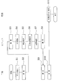
- FIG. 4 relates to a process for aligning the object 2 according to the embodiment, that is, a plant alignment method for aligning the first object 4 and the second object 6 to be joined.
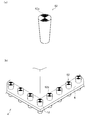
- a plug 52 as shown in FIG. 5A is prepared.
- the plug 52 is an inverted truncated cone-shaped component whose diameter increases as it approaches the head, and a target 52a is marked on the head.
- the plug 52 has a first hole formed in the flange 8 of the first object 4 so that the target 52a is located on the surface opposite to the surface to be joined of the flange 8. It is inserted into the portion 12.
- the plug 52 Since the plug 52 has a shape that increases in diameter as it approaches the head, it is inserted into the first hole portion 12 without a gap (insertion step, step S1). Similarly, at the B factory, the plug 52 is prepared and inserted into the second hole portion 14 formed in the flange 10 of the second object 6.
- the first object 4 is photographed using the camera 38 with the plug 52 (first jig) inserted into the first hole 12 of the flange 8 (photographing step, step S2).
- Shooting is done from various angles.
- the camera 38 a digital camera, a smartphone, or the like is used.
- the second object 6 is used with the camera 39 with the plug 52 (second jig) inserted into the second hole 14 of the flange 10. Is taken.
- the plurality of captured images are recorded in the terminal 40 as a first two-dimensional image data group in the A factory, and recorded in the terminal 42 as a second two-dimensional image data group in the B factory.
- the terminals 40 and 42 include a personal computer, and for recording the first two-dimensional image data group and the second two-dimensional image data group in the terminal 40, for example, a memory card or the like is used as a camera 38, 39. This is done by replacing the terminal with the terminals 40 and 42.
- the first two-dimensional image data group of the first object 4 and the second two-dimensional image data group of the second object 6 taken are the plants arranged in the offices in country Z from the terminals 40 and 42. It is transmitted to the alignment device 20 by, for example, e-mail.
- the conversion unit 26 converts them into one first three-dimensional image data. (Conversion step, step S4).
- each of the first two-dimensional image data is joined via the singular point 16 included in the first two-dimensional image data. Further, the scale of each two-dimensional image data is unified via the scale 18.
- the second two-dimensional image data group is converted into one second three-dimensional image data after receiving the second two-dimensional image data group.
- the conversion to three-dimensional image data is performed using a known technique.
- the first three-dimensional image data and the second three-dimensional image data are stored in the storage unit 28.
- the control unit 22 reads out the first three-dimensional image data and the second three-dimensional image data from the storage unit 28, and displays, for example, images based on the respective three-dimensional image data on the display unit 30 side by side.
- the image may be displayed on the display unit 30 by the operator's own operation.
- the operator designates the target 52a, which is the origin of each, by a touch operation or the like while looking at the image of the first object 4 and the image of the second object 6 displayed on the display unit 30 (designation step, Step S5).
- the operator sets the three-dimensional coordinate axes with respect to the origin in the first three-dimensional image data and the second three-dimensional image data, respectively (setting step, step S6). In this way, by setting the three-dimensional coordinate axes in the first three-dimensional image data and the second three-dimensional image data, respectively, the center positions of the first hole portion 12 and the second hole portion 14 can be objectively recognized. become.
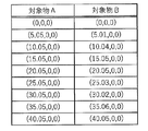
- control unit 22 specifies the coordinates on the three-dimensional coordinate axes of each target 52a in the image based on each three-dimensional image data, and then displays a table of the specified coordinates as shown in FIG. It may be displayed in. These tables and the first three-dimensional image and the second three-dimensional image may be displayed together, or only one of them may be displayed.
- the operator looks at the coordinate table, the first three-dimensional image, and the second three-dimensional image displayed on the display unit 30, and the corresponding target in the first three-dimensional image data and the second three-dimensional image data. Aligning the 52a with each other, that is, confirming the coordinate position between the corresponding targets 52a (position confirmation step, step S7).
- the operator grasps the target 52a whose corresponding coordinate position is not within the tolerance, and the operator is in charge of the position of the first hole 12 in which the target 52a whose corresponding coordinate position is not within the margin of error is arranged. Contact the staff by phone or other means.
- the worker in charge of the second object 6 is contacted by telephone or the like (communication step, step S8). ..
- the first hole portion 12 and the second hole portion 14 corresponding to the target 52a are expanded or made into long holes.
- the first object 4 is shipped from the A factory and the second object 6 is shipped from the B factory to the construction site in Y country (shipping process, step S10). ). If it is sufficient that the modification is performed on either the first object 4 or the second object 6, either the first object 4 or the second object 6 is shipped without being modified. .. In this case, in the communication step (step S8), it is not necessary to contact the worker in charge of the object 2 that does not need to be modified.
- the first object 4 in which the plug 52 having the target 52a marked on the head is inserted into the first hole portion 12, and the plug 52 is inserted into the second hole portion 14.
- the first object 6 is photographed and the two-dimensional image data of the first object 4 and the second object 6 are converted into three-dimensional image data to set the three-dimensional coordinate axes.
- the error in the center position of the hole portion 12 and the second hole portion 14 can be accurately grasped. Therefore, by grasping such an error in advance, performing work to correct this error in advance at the factory, and then shipping the first object 4 and the second object 6 to the construction site, the first object at the construction site. It is possible to easily and accurately align the joint portion between the object 4 and the second object 6.
- the same effect as Trial fit up can be obtained by using the three-dimensional image data, and the alignment work at the factory or the construction site becomes unnecessary. , The cost of alignment can be significantly reduced and the schedule can be reduced.
- the first object 4 and the second object 6 are located in X, the construction site is located in Y, and the plant alignment device 20 is used.
- the first object 4, the second object 6, the plant alignment device 20, and the construction site may be located at slightly distant places on the same site.
- the acquisition unit does not necessarily have to be the communication unit 24, and may be, for example, wiredly connected to the camera 38, 39 or the terminals 40, 42.
- the input unit 32 is not limited to the touch panel, and may be, for example, a mouse, a keyboard, or the like.
- the operator operates the mouse while looking at the display unit 30, and designates the target 52a as the origin with the pointer.
- the first two-dimensional image data group and the second two-dimensional image data group after shooting do not necessarily have to be stored in the terminals 40 and 42.
- a memory card or a CD in which the first two-dimensional image data group and the second two-dimensional image data group are recorded may be mailed to an office in country Z.
- the first two-dimensional image data group and the second two-dimensional image data group are read into the plant alignment device 20.
- the first two-dimensional image data group and the second two-dimensional image data group after shooting may be directly transmitted from the shooting machines 38 and 39 to the plant alignment device 20 by e-mail or the like.
- the three-dimensional coordinate axes with reference to the origin are set manually, but the information of the designated origin is used.
- the control unit 22 may set the three-dimensional coordinate axes with respect to the origin in the first three-dimensional image data and the second three-dimensional image data.
- the control unit 22 may determine whether or not the coordinate error of each target 52a is within a preset tolerance. For example, as shown in FIG. 7, the target 52a within the margin of error is displayed with “ ⁇ ” or the like, and the target 52a not within the margin of error is displayed with “ ⁇ ” or the like. Note that FIG. 7 illustrates a case where an error of less than 0.04 is within the allowable range. Further, the margin of error can be freely set by an operator or the like, and the set margin of error is stored in a storage unit (not shown).
- the control unit 22 uses the coordinates of the target 52a, which is not within the permissible error, as alignment information via the communication unit 24, and the terminal 40 of the factory A and the terminal of the factory B B. It is transmitted to 42 (contact process, step S8). Specifically, the coordinates (5.05, 0, 0) of the first object 4 and the corresponding coordinates (5.01, 0, 0) of the second object 6 are transmitted by e-mail or the like. Make a notification.
- the terminals 40 and 42 that have received the notification notify the person in charge of the factory A that manages the terminal 40 and the person in charge of the factory B that manages the terminal 42 that they have received the coordinate notification by means of notification such as an alarm. ..
- the person in charge of receiving the notification reports the contents of the notification to the worker in charge of the first object 4 and the worker in charge of the second object 6, respectively.
- the information transmitted in the communication process is not necessarily limited to the coordinates of the target 52a that are not within the tolerance, and the coordinates of the corresponding pair of targets 52a are used as the alignment information to the terminal 40 of the factory A and the terminal 42 of the factory B. You may send it.
- the plug 52 is used as a jig in which the target 52a is displayed on the head, but as a jig other than the plug 52, for example, a peg, a wedge, or the like is used as a tool for positioning. May be used as.
Landscapes
- Physics & Mathematics (AREA)
- General Physics & Mathematics (AREA)
- Engineering & Computer Science (AREA)
- Theoretical Computer Science (AREA)
- Computer Graphics (AREA)
- Computer Vision & Pattern Recognition (AREA)
- Image Processing (AREA)
- Length Measuring Devices By Optical Means (AREA)
- General Factory Administration (AREA)
Abstract
Description
しかし、この位置合わせ装置のように、設計情報を用いた場合、設計情報には公差が含まれていないため、正確な位置合わせをすることは困難であった。
本発明の目的は、接合部の位置合わせを容易かつ正確に行うことができるプラント用位置合わせ方法を提供することである。
接合の対象となる第1対象物と第2対象物の位置合わせを行うプラント用位置合わせ方法であって、
頭部にターゲットが標示された第1治具を前記第1対象物に形成された第1孔部に挿入すると共に、頭部にターゲットが標示された第2治具を前記第2対象物に形成された第2孔部に挿入する挿入工程、
前記第1治具が前記第1孔部に挿入された前記第1対象物を複数撮影し、前記第2治具が前記第2孔部に挿入された前記第2対象物を複数撮影する撮影工程、
前記撮影工程にて撮影された前記第1対象物の複数の二次元画像データである第1二次元画像データ群を取得すると共に、前記第2対象物の複数の二次元画像データである第2二次元画像データ群を取得する取得工程、
前記第1二次元画像データ群を第1三次元画像データ、前記第2二次元画像データ群を第2三次元画像データにそれぞれ変換する変換工程、
前記第1三次元画像データに基づく画像および前記第2三次元画像データに基づく画像において、それぞれ原点となる前記ターゲットを指定する指定工程、
前記指定工程により指定された原点の情報を用いて、前記第1三次元画像データおよび前記第2三次元画像データにおいて前記原点を基準とする三次元座標を設定する設定工程、
前記第1三次元画像データおよび前記第2三次元画像データにおいて対応する前記ターゲット同士の位置確認を行う位置確認工程
を含むことを特徴とする。
前記位置確認工程で得られた位置合わせ情報に基づいて前記第1孔部および前記第2孔部の少なくとも一方を修正する修正工程
をさらに含むことを特徴とする。
すなわち、事前に三次元画像データを用いて位置確認が行われているため、位置確認工程で得られた位置合わせ情報を用いることにより、必要な孔部のみを迅速に修正(孔部を拡張したり、長穴にしたりするなど)できる。
前記修正工程により前記第1孔部および前記第2孔部の少なくとも一方が修正された状態で前記第1対象物および前記第2対象物を出荷する出荷工程、
前記出荷工程で出荷された前記第1対象物および前記第2対象物を接合する接合工程
を含むことを特徴とする。
すなわち、事前に三次元画像データを用いて位置確認が行われ、孔部の修正が行われた状態で対象物が建設現場に出荷されるため、建設現場においては位置合わせ作業や修正作業を行う必要がなく容易かつ迅速、低コストで組み立て作業ができる。
前記第1治具および前記第2治具が、逆円錐形状を有するプラグであることを特徴とする。
このように、位置合わせに用いる治具としては、逆円錐形状のプラグを用いるのが好適である。
前記第1対象物と前記第2対象物を接合して完成される対象物は、プラント用大型機器であることを特徴とする。
このように、本発明のプラント用位置合わせ方法によれば、プラント用大型機器を接合する場合に、工場において建設機械や足場などを用いた大掛かりな仮合わせ作業が必要でなくなるため、工場での作業負担を低減することができる。
4 第1対象物
6 第2対象物
8 第1フランジ
10 第2フランジ
12 第1孔部
14 第2孔部
16 特異点
18 スケール
20 プラント用位置合わせ装置
22 制御部
24 通信部
26 変換部
28 記憶部
30 表示部
32 入力部
38 第1撮影機
39 第2撮影機
40 端末
42 端末
52 プラグ(治具)
52a ターゲット
Claims (5)
- 接合の対象となる第1対象物と第2対象物の位置合わせを行うプラント用位置合わせ方法であって、
頭部にターゲットが標示された第1治具を前記第1対象物に形成された第1孔部に挿入すると共に、頭部にターゲットが標示された第2治具を前記第2対象物に形成された第2孔部に挿入する挿入工程、
前記第1治具が前記第1孔部に挿入された前記第1対象物を複数撮影し、前記第2治具が前記第2孔部に挿入された前記第2対象物を複数撮影する撮影工程、
前記撮影工程にて撮影された前記第1対象物の複数の二次元画像データである第1二次元画像データ群を取得すると共に、前記第2対象物の複数の二次元画像データである第2二次元画像データ群を取得する取得工程、
前記第1二次元画像データ群を第1三次元画像データ、前記第2二次元画像データ群を第2三次元画像データにそれぞれ変換する変換工程、
前記第1三次元画像データに基づく画像および前記第2三次元画像データに基づく画像において、それぞれ原点となる前記ターゲットを指定する指定工程、
前記指定工程により指定された原点の情報を用いて、前記第1三次元画像データおよび前記第2三次元画像データにおいて前記原点を基準とする三次元座標を設定する設定工程、
前記第1三次元画像データおよび前記第2三次元画像データにおいて対応する前記ターゲット同士の位置確認を行う位置確認工程
を含むことを特徴とするプラント用位置合わせ方法。 - 前記位置確認工程で得られた位置合わせ情報に基づいて前記第1孔部および前記第2孔部の少なくとも一方を修正する修正工程
をさらに含むことを特徴とする請求項1記載のプラント用位置合わせ方法。 - 前記修正工程により前記第1孔部および前記第2孔部の少なくとも一方が修正された状態で前記第1対象物および前記第2対象物を出荷する出荷工程、
前記出荷工程で出荷された前記第1対象物および前記第2対象物を接合する接合工程
を含むことを特徴とする請求項2記載のプラント用位置合わせ方法。 - 前記第1治具および前記第2治具は、逆円錐形状を有するプラグであることを特徴とする請求項1~3の何れか一項に記載のプラント用位置合わせ方法。
- 前記第1対象物と前記第2対象物を接合して完成される対象物は、プラント用大型機器であることを特徴とする請求項1~4の何れか一項に記載のプラント用位置合わせ方法。
Priority Applications (4)
| Application Number | Priority Date | Filing Date | Title |
|---|---|---|---|
| JP2021521698A JP7152604B2 (ja) | 2019-05-30 | 2019-05-30 | 位置合わせ方法および位置合わせ装置 |
| US17/613,079 US11810315B2 (en) | 2019-05-30 | 2019-05-30 | Alignment method for use in plant |
| PCT/JP2019/021578 WO2020240784A1 (ja) | 2019-05-30 | 2019-05-30 | プラント用位置合わせ方法 |
| KR1020217038767A KR102741370B1 (ko) | 2019-05-30 | 2019-05-30 | 플랜트에서 사용하기 위한 위치 맞춤 방법 |
Applications Claiming Priority (1)
| Application Number | Priority Date | Filing Date | Title |
|---|---|---|---|
| PCT/JP2019/021578 WO2020240784A1 (ja) | 2019-05-30 | 2019-05-30 | プラント用位置合わせ方法 |
Publications (1)
| Publication Number | Publication Date |
|---|---|
| WO2020240784A1 true WO2020240784A1 (ja) | 2020-12-03 |
Family
ID=73552805
Family Applications (1)
| Application Number | Title | Priority Date | Filing Date |
|---|---|---|---|
| PCT/JP2019/021578 Ceased WO2020240784A1 (ja) | 2019-05-30 | 2019-05-30 | プラント用位置合わせ方法 |
Country Status (4)
| Country | Link |
|---|---|
| US (1) | US11810315B2 (ja) |
| JP (1) | JP7152604B2 (ja) |
| KR (1) | KR102741370B1 (ja) |
| WO (1) | WO2020240784A1 (ja) |
Families Citing this family (1)
| Publication number | Priority date | Publication date | Assignee | Title |
|---|---|---|---|---|
| CN115409835B (zh) * | 2022-10-31 | 2023-02-17 | 成都浩目科技有限公司 | 三维成像方法、装置、电子设备、系统和可读存储介质 |
Citations (2)
| Publication number | Priority date | Publication date | Assignee | Title |
|---|---|---|---|---|
| JPH11153438A (ja) * | 1997-11-21 | 1999-06-08 | Hitachi Plant Eng & Constr Co Ltd | 芯出治具及びそれを用いた測定装置 |
| JP2003028614A (ja) * | 2001-07-12 | 2003-01-29 | Toyota Industries Corp | 位置検出方法、位置検出装置、産業車両、マーク、荷役用パレット、荷役用棚、貼付用シート及び荷役システム |
Family Cites Families (1)
| Publication number | Priority date | Publication date | Assignee | Title |
|---|---|---|---|---|
| JP2012068062A (ja) * | 2010-09-21 | 2012-04-05 | Fuji Xerox Co Ltd | 位置合わせ装置、位置合わせシステム及び位置合わせプログラム |
-
2019
- 2019-05-30 WO PCT/JP2019/021578 patent/WO2020240784A1/ja not_active Ceased
- 2019-05-30 KR KR1020217038767A patent/KR102741370B1/ko active Active
- 2019-05-30 JP JP2021521698A patent/JP7152604B2/ja active Active
- 2019-05-30 US US17/613,079 patent/US11810315B2/en active Active
Patent Citations (2)
| Publication number | Priority date | Publication date | Assignee | Title |
|---|---|---|---|---|
| JPH11153438A (ja) * | 1997-11-21 | 1999-06-08 | Hitachi Plant Eng & Constr Co Ltd | 芯出治具及びそれを用いた測定装置 |
| JP2003028614A (ja) * | 2001-07-12 | 2003-01-29 | Toyota Industries Corp | 位置検出方法、位置検出装置、産業車両、マーク、荷役用パレット、荷役用棚、貼付用シート及び荷役システム |
Also Published As
| Publication number | Publication date |
|---|---|
| US11810315B2 (en) | 2023-11-07 |
| KR102741370B1 (ko) | 2024-12-11 |
| KR20220015395A (ko) | 2022-02-08 |
| JPWO2020240784A1 (ja) | 2020-12-03 |
| US20220230349A1 (en) | 2022-07-21 |
| JP7152604B2 (ja) | 2022-10-12 |
Similar Documents
| Publication | Publication Date | Title |
|---|---|---|
| US11087457B1 (en) | Digital projection system and associated method | |
| KR101490311B1 (ko) | 레이저 스캐너를 이용한 플랜트 구조물의 품질 및 시공성 검사방법 | |
| JP4167954B2 (ja) | ロボット及びロボット移動方法 | |
| KR101876856B1 (ko) | 증강현실을 이용한 유지 보수 시스템 및 이의 제어방법 | |
| CN110125926A (zh) | 自动化的工件取放方法及系统 | |
| KR20160107128A (ko) | 작업재의 가상조립을 통해 어셈블리 시스템을 트레이닝 하기 위한 비전시스템 | |
| CN115741720B (zh) | 基于双目视觉技术及lm算法的机器人的零点标定系统及其方法 | |
| CN109814434B (zh) | 控制程序的校准方法及装置 | |
| CN105081394A (zh) | 用于全尺寸决定性装配的路径可重复加工 | |
| JPWO2016068235A1 (ja) | 部品加工支援システムおよび方法 | |
| KR20210103840A (ko) | 드론을 활용한 객체의 포인트 클라우드 추출방법 및 3차원 공간정보 구축 시스템 | |
| JP2019045962A (ja) | 鉄筋位置確認システム | |
| US20210011456A1 (en) | Component management database, component management system, and component management method | |
| WO2020240784A1 (ja) | プラント用位置合わせ方法 | |
| JP7336253B2 (ja) | 据付物の施工方法 | |
| JP5077698B2 (ja) | プレゼンテーション資料配信システム、及びプレゼンテーション資料上の指示位置データの配信システム | |
| CN117681207A (zh) | 参数偏差确定方法、装置、工装、存储介质及计算机设备 | |
| JP2009217694A (ja) | 検査システム | |
| CN113119087B (zh) | 壳管胀接控制方法、系统和存储介质 | |
| JP2020126414A (ja) | 機械学習用教師データ作成支援方法、及び機械学習用教師データ作成支援プログラム | |
| KR20210112551A (ko) | 휴대용 단말기를 이용한 건설 분야 시공 관리 시스템 및 방법 | |
| KR20240045594A (ko) | 3차원 깊이 측정센서를 이용한 곡블록 용접방법 | |
| JP5346674B2 (ja) | マーキング制御システム及びこれを用いてマーキングされた部材同士の位置合わせ方法 | |
| JP2019011564A (ja) | 現場画像出力システム | |
| JP2005267404A (ja) | ワーク加工システム及びワーク加工方法 |
Legal Events
| Date | Code | Title | Description |
|---|---|---|---|
| 121 | Ep: the epo has been informed by wipo that ep was designated in this application |
Ref document number: 19930515 Country of ref document: EP Kind code of ref document: A1 |
|
| ENP | Entry into the national phase |
Ref document number: 2021521698 Country of ref document: JP Kind code of ref document: A |
|
| ENP | Entry into the national phase |
Ref document number: 20217038767 Country of ref document: KR Kind code of ref document: A |
|
| NENP | Non-entry into the national phase |
Ref country code: DE |
|
| 122 | Ep: pct application non-entry in european phase |
Ref document number: 19930515 Country of ref document: EP Kind code of ref document: A1 |