WO2020237989A1 - 一种快频脉冲tig焊接系统 - Google Patents
一种快频脉冲tig焊接系统 Download PDFInfo
- Publication number
- WO2020237989A1 WO2020237989A1 PCT/CN2019/112886 CN2019112886W WO2020237989A1 WO 2020237989 A1 WO2020237989 A1 WO 2020237989A1 CN 2019112886 W CN2019112886 W CN 2019112886W WO 2020237989 A1 WO2020237989 A1 WO 2020237989A1
- Authority
- WO
- WIPO (PCT)
- Prior art keywords
- sic
- resistor
- module
- diode
- frequency
- Prior art date
- Legal status (The legal status is an assumption and is not a legal conclusion. Google has not performed a legal analysis and makes no representation as to the accuracy of the status listed.)
- Ceased
Links
Images



Classifications
-
- B—PERFORMING OPERATIONS; TRANSPORTING
- B23—MACHINE TOOLS; METAL-WORKING NOT OTHERWISE PROVIDED FOR
- B23K—SOLDERING OR UNSOLDERING; WELDING; CLADDING OR PLATING BY SOLDERING OR WELDING; CUTTING BY APPLYING HEAT LOCALLY, e.g. FLAME CUTTING; WORKING BY LASER BEAM
- B23K9/00—Arc welding or cutting
- B23K9/09—Arrangements or circuits for arc welding with pulsed current or voltage
- B23K9/091—Arrangements or circuits for arc welding with pulsed current or voltage characterised by the circuits
-
- B—PERFORMING OPERATIONS; TRANSPORTING
- B23—MACHINE TOOLS; METAL-WORKING NOT OTHERWISE PROVIDED FOR
- B23K—SOLDERING OR UNSOLDERING; WELDING; CLADDING OR PLATING BY SOLDERING OR WELDING; CUTTING BY APPLYING HEAT LOCALLY, e.g. FLAME CUTTING; WORKING BY LASER BEAM
- B23K9/00—Arc welding or cutting
- B23K9/10—Other electric circuits therefor; Protective circuits; Remote controls
- B23K9/1006—Power supply
- B23K9/1043—Power supply characterised by the electric circuit
-
- B—PERFORMING OPERATIONS; TRANSPORTING
- B23—MACHINE TOOLS; METAL-WORKING NOT OTHERWISE PROVIDED FOR
- B23K—SOLDERING OR UNSOLDERING; WELDING; CLADDING OR PLATING BY SOLDERING OR WELDING; CUTTING BY APPLYING HEAT LOCALLY, e.g. FLAME CUTTING; WORKING BY LASER BEAM
- B23K9/00—Arc welding or cutting
- B23K9/16—Arc welding or cutting making use of shielding gas
- B23K9/167—Arc welding or cutting making use of shielding gas and of a non-consumable electrode
Definitions
- the invention relates to the technical field of welding equipment, and more specifically to a fast-frequency pulse TIG welding system.
- argon tungsten arc welding (TIG welding for short) is widely used for its advantages such as stable arc, zero spatter, high welding quality, and wide range of weldable metals.
- Pulse TIG welding technology which started in the mid-1960s, superimposes a pulse current with a certain frequency on the basis of traditional DC arc welding.
- the peak current can keep the arc stable and accelerate the melting of the base material to form a molten pool.
- the base current is both
- the heat input can be controlled and the arc can continue to burn, so that the molten pool is cooled and crystallized. The two cycles alternately to form a weld with good performance.
- the quality of the welding power source is closely related to the performance of the welding arc. It not only needs to accurately provide energy for the welding process, but also needs to achieve coordinated operation with other equipment in the system. However, there is still a big gap between the industrialization level of domestic fast-frequency pulse TIG welding equipment and developed countries.
- Welding power sources generally use Si-based IGBTs as the main power conversion devices, while the switching performance of traditional Si-based power devices has been Close to the theoretical limit determined by its material properties, to a certain extent, it restricts the inverter frequency and response speed of the welding power supply and several key indicators that affect the reliability of fast-frequency pulse TIG welding, making the overall size of the machine too large and the dynamic characteristics good.
- the power switch device of the fast-frequency pulse TIG welding power supply of the present invention adopts a new type of SiC power switch tube, and the inverter frequency is up to 100kHz, which is nearly ten times higher than that of the currently more commonly used IGBT. Not only the size of the whole machine is greatly reduced, but also Good dynamic response speed; help to strengthen the high frequency arc control effect, stably output the 20kHz fast frequency pulse current waveform, the waveform is stable and undistorted during the welding process; the fast frequency pulse TIG welding power supply has extremely high energy efficiency; due to the SiC power switch tube Its own excellent performance, its switching loss and conduction loss are small, greatly improving the energy efficiency of TIG welding power supply.
- the purpose of the present invention is to provide a regular fast frequency with high inverter frequency, good dynamic characteristics and stability, reduced power tube switching loss, and stable output of 20kHz and above.
- Fast frequency pulse TIG welding system with pulse flexible current waveform is provided.
- a fast-frequency pulse TIG welding system characterized in that it includes a fast-frequency pulse TIG welding power source;
- the fast-frequency pulse TIG welding power source includes a main circuit and a control circuit And human-computer interaction system;
- the main circuit includes a power frequency rectification filter module, a pulse current main circuit, a base current main circuit, and a high-frequency current switching circuit;
- the pulse current main circuit includes a SiC full-bridge inverse conversion current module connected in sequence.
- Voltage module one and SiC rectification and smoothing module one
- the base value current main circuit includes a SiC full-bridge inverse conversion module two, a high-frequency transformer module two, and a SiC rectification and smoothing module two connected in sequence;
- the high-frequency current switching circuit It includes a high-frequency switching module and an anti-reverse irrigation module connected in sequence;
- the SiC full-bridge reverse conversion current module includes a SiC power switch tube;
- the three-phase AC input power supply is connected to the power frequency rectification filter module;
- the power frequency rectification filter module is connected to the SiC full-bridge inverse conversion flow module 1 and the SiC full-bridge inverse conversion flow module 2;
- the SiC rectification and smoothing module 1 is connected to high-frequency switching Module connection; anti-reverse irrigation module connected with external arc load; SiC rectifier smoothing module 2 connected with external arc load;
- the control circuit includes an ARM minimum control system, and a human-computer interaction communication module connected to the ARM minimum control system, a SiC high-frequency drive circuit, a switch drive circuit, and an output voltage and current sampling feedback circuit; wherein, the SiC high-frequency drive circuit Connected to SiC full-bridge inverse conversion current module 1 and SiC full-bridge inverse conversion current module 2 respectively; the switch drive circuit is connected to the high-frequency switching module; the output voltage and current sampling feedback circuit is connected to the external arc load and the SiC rectifier smoothing module 1 and SiC rectifying and smoothing module two is connected; the man-machine interactive communication module is connected with the man-machine interactive system.
- the first SiC full-bridge inverse conversion current module includes SiC power switch tubes, which means: the first SiC full-bridge inverse conversion current module includes SiC power switch tubes M101, SiC power switch tubes M102, SiC power switch tubes M103, and SiC Power switch tube M104; the high-frequency transformer module one includes a high-frequency transformer one T101; the SiC power switch tube M101, SiC power switch tube M102, SiC power switch tube M103 and SiC power switch tube M104 form a full-bridge inverter The circuit is then connected to the primary of a high-frequency transformer T101 through a blocking capacitor C109; the SiC power switch tube M101, SiC power switch tube M102, SiC power switch tube M103, and SiC power switch tube M104 are respectively connected in parallel with an RC absorption circuit 1 ;
- the first SiC rectifier and smoothing module includes a rectifier diode VD101, a rectifier diode VD102, and an inductor L101; the secondary first output end of the high-frequency transformer-T101 is connected to the rectifier diode VD101 and the rectifier diode VD102 and the high-frequency transformer-T101 in sequence.
- the third output terminal of the stage is connected; the connection of the rectifier diode VD101 and the rectifier diode VD102 is connected to one end of the inductor L101; the other end of the inductor L101 and the secondary output terminal of the high-frequency transformer T101 are respectively used as the output of the pulse current main circuit
- the terminal is connected with the high-frequency switching module.
- the SiC power switch tube M101, the SiC power switch tube M102, the SiC power switch tube M103, and the SiC power switch tube M104 form a full-bridge inverter circuit, and then pass through the DC blocking capacitor C109 and the high-frequency transformer module.
- Primary connection; the SiC power switch tube M101, SiC power switch tube M102, SiC power switch tube M103, and SiC power switch tube M104 are respectively connected in parallel with RC absorption circuit one, which means:
- It also includes a capacitor C101, a capacitor C102, a capacitor C103, a capacitor C104, a capacitor C109, a resistor R101, a resistor R102, a resistor R103, and a resistor R104;
- the circuit formed by the series connection of the SiC power switch tube M102 and the SiC power switch tube M104 is connected in parallel to the power frequency rectifier filter circuit; the capacitor C101 and the resistor R101 are connected in parallel to the SiC On the power switch M101; the capacitor C102 and the resistor R102 are connected in series and then connected in parallel to the SiC power switch M102; the capacitor C103 and the resistor R103 are connected in series and then connected in parallel to the SiC power switch M103; the capacitor C104 and the resistor R104 are connected in series and connected in parallel to the SiC power switch On the tube M104; the connection between the SiC power switch tube M101 and the SiC power switch tube M103 is connected in series with the capacitor C109 and then connected to the primary first input terminal of the high frequency transformer module one; the SiC power switch tube M102 and the SiC power The connection of the switch tube M104 is connected with the primary second input terminal of the high-frequency transformer module one
- the circuit structure of the SiC full-bridge inverse conversion module two is the same as that of the SiC full-bridge inverse conversion module one; the circuit structure of the high-frequency transformer module two is the same as the high-frequency transformer module one; and the SiC rectifier smoothing module two
- the circuit structure is the same as that of the SiC rectification and smoothing module.
- the high-frequency switching module includes a modulation switching tube IGBT Q202 and a modulation switching tube IGBT Q201;
- the anti-reverse irrigation module includes a rectifier diode VD201;
- the modulation switching tube IGBT Q201 is connected in parallel to the SiC rectification and smoothing module one SiC rectification and smoothing module one is connected to the external arc load through the modulation switch tube IGBT Q202 and rectifier diode VD201 connected in sequence;
- the modulation switch tube IGBT Q202 is connected in parallel with a peak voltage absorption module one;
- the modulation switch tube IGBT Q201 is connected in parallel with peak voltage absorption Module two.
- the peak voltage absorption module 1 includes a capacitor C202, a resistor R202, a diode D204, and a diode D203; the resistor R202 and the capacitor C202 are connected in parallel and the circuit formed in series with the diode D204 is connected in parallel to the modulation switch IGBT Q202; the diode D203 is connected in parallel Modulation switch tube IGBT Q202;
- the second peak voltage absorption module includes a capacitor C201, a resistor R201, a diode D202, and a diode D201; the resistor R201 and the diode D202 are connected in parallel with the capacitor C201 to form a circuit connected in parallel to the modulation switch IGBT Q201; the diode D201 is connected in parallel to the modulation switch IGBT Q201 on.
- the ARM minimum control system is connected to the SiC high frequency drive circuit through isolation one; the ARM minimum control system is connected to the switch drive circuit through isolation two.
- the ARM minimum control system is connected to the SiC high-frequency drive circuit through isolation one, which means:
- the ARM minimum control system is connected to the SiC high-frequency drive circuit through the ISO5451 isolation drive chip, and the isolation drive chip is also connected to drive power supply circuit one;
- the SiC high-frequency drive circuit includes capacitor C304, capacitor C305, Zener tube ZD301, diode D302, diode D303, resistor R310, resistor R311, resistor R312, and resistor R313; the pin CLAMP of the isolation drive chip and the SiC power switch grid Pole connection; the gate of the SiC power switch is connected to the ground through the parallel resistor R313 and the capacitor C305; the pin OUT of the isolation drive chip is connected to the gate of the SiC power switch through the resistor R312; the diode D303 and the resistor R311 are connected in parallel to the resistor R312 in series The pin OUT of the isolation drive chip is connected to the drain of the SiC power switch through the series resistor R310 and diode D302; the pin OUT of the isolation drive chip is also grounded through the parallel capacitor C304 and the Zener diode ZD301; the lead of the isolation drive chip The pin DESAT is connected to the pin OUT of the isolation driver chip.
- the ARM minimum control system is connected to the switch drive circuit through isolation two, which means that the ARM minimum control system is connected to the switch drive circuit through an optocoupler isolation chip;
- the switch drive circuit includes NPN transistors Q401, NPN Transistor Q402, NPN transistor Q404, PNP transistor Q403 and driving power supply circuit two;
- the output terminal of the optocoupler isolation chip is connected to the base of the NPN transistor Q401 through the resistor R402, the resistor R403 and the diode D402 connected in sequence; the resistor R403 is connected in parallel with the capacitor C401; the diode D402 is connected in reverse parallel with the diode D403; the resistor R403 and the diode D402 are connected.
- the collector of the NPN transistor Q401 is connected through a diode D401; the collector of the NPN transistor Q401 is also connected to the two anodes of the driving power supply circuit through a resistor R404;
- connection of the resistor R402 and the resistor R403 is connected to the base of the NPN transistor Q402 through the resistor R408 and the diode D408 connected in turn; the resistor R408 is connected in parallel with the capacitor C403; the diode D408 is connected in reverse parallel with the diode D409; the resistor R408 and the diode D408 are connected through the diode D407 Connect with the collector of the NPN transistor Q402; the collector of the NPN transistor Q402 is also connected to the two positive poles of the driving power supply circuit through a resistor R409; the emitter of the NPN transistor Q401 and the emitter of the NPN transistor Q402 are respectively connected to the second negative pole of the driving power supply circuit;
- the collector of the NPN transistor Q401 is connected to the base of the PNP transistor Q403 through the resistor R405 and the diode D405 connected in sequence; the resistor R405 is connected in parallel with the capacitor C402; the diode C405 is connected in reverse parallel with the diode D404; the resistor R405 and the diode D405 are connected to the PNP through the diode D406
- the collector of the transistor Q403 is connected; the base of the PNP transistor Q403 is connected to the two positive poles of the drive power supply circuit through a resistor R406; the emitter of the PNP transistor Q403 is connected to the two positive poles of the drive power supply circuit through a resistor R407;
- the collector of the NPN transistor Q402 is connected to the base of the NPN transistor Q404 through the resistor R410 and the diode D411 connected in sequence; the resistor R410 is connected in parallel with the capacitor C404; the diode D411 is connected in reverse parallel with the diode D412; the resistor R410 and the diode D411 are connected through the diode D410 and NPN
- the collector of the transistor Q404 is connected; the collector of the NPN transistor Q404 is connected to the collector of the PNP transistor Q403; the emitter of the NPN transistor Q404 is connected to the second negative electrode of the driving power supply circuit through the resistor R411; the collector of the NPN transistor Q404 is connected to the second negative electrode of the driving power supply circuit through the resistor R412 ;
- the collector of the NPN transistor Q404 is connected to the high-frequency switching module.
- it further includes an industrial robot, a wire feeder, a welding gun, an air supply device, and a fixture; the industrial robot and the wire feeder are respectively connected to the ARM minimum control system; the fixture is respectively connected to the industrial robot and the welding torch; the fast frequency
- the pulse TIG welding power source is also connected with an air supply device; the welding gun is also connected with an air supply device and a wire feeder respectively.
- the present invention has the following advantages and beneficial effects:
- the power switch device of the fast-frequency pulsed TIG welding power supply of the present invention adopts a new type of SiC power switch tube, and the inverter frequency is as high as 100kHz and above, which is nearly improved compared to the more commonly used IGBT.
- the inverter frequency is as high as 100kHz and above, which is nearly improved compared to the more commonly used IGBT.
- the fast frequency pulse TIG welding power source has extremely high energy efficiency; due to the excellent performance of the SiC power switch tube itself, its switching loss and conduction loss are small, which greatly improves the energy efficiency of the TIG welding power source;
- the high-frequency current switching circuit can effectively absorb the spike overvoltage generated by the high-frequency pulse current modulation process without destroying the basic waveform of the fast-frequency pulse current, with simple structure, low cost and high reliability;
- the sampling isolation method of the present invention realizes the ARM minimum control system and the SiC high frequency drive circuit, and the ARM minimum control system is connected with the switch drive circuit; it has multiple protection functions, which can effectively drive the switch tube while preventing the occurrence of the switch tube Damage; it can suppress the transient voltage and transient current excessively high and electromagnetic interference in the driving process of the SiC power switch tube, and prevent the voltage spike from causing false triggering, and has a good driving effect;
- the fast-frequency pulse TIG welding system of the present invention combines high-frequency inverter, digital automatic control and other technologies, as well as coordinated operation of various parts of the system through the CAN bus, which makes the system more integrated and more precise in control.
- FIG. 1 is a system block diagram of the fast frequency pulse TIG welding system of the present invention
- FIG. 2 is a schematic diagram of the structure of the fast-frequency pulse TIG welding power source in the fast-frequency pulse TIG welding system of the present invention
- Figure 3 is a circuit diagram of the main circuit of the fast pulse TIG welding power supply in the fast pulse TIG welding system of the present invention
- FIG. 4 is a circuit diagram of the SiC high frequency drive circuit of the fast pulse TIG welding power source in the fast pulse TIG welding system of the present invention
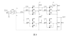
- Fig. 5 is a circuit diagram of the switch drive circuit of the fast pulse TIG welding power supply in the fast pulse TIG welding system of the present invention
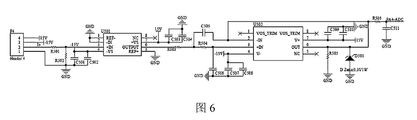
- FIG. 6 is a circuit diagram of the output voltage and current sampling feedback circuit of the fast pulse TIG welding power supply in the fast pulse TIG welding system of the present invention
- Fig. 7 is a structural block diagram of the wire feeder in the fast-frequency pulse TIG welding system of the present invention.
- a fast-frequency pulse TIG welding system of this embodiment has a structure as shown in Figures 1 to 7, including a fast-frequency pulse TIG welding power source, and also includes an industrial robot, a wire feeder, a welding gun, an air supply device and a fixture; an industrial robot and The wire feeders are respectively connected to the ARM minimum control system; the fixtures are respectively connected to the industrial robot and the welding torch; the fast frequency pulse TIG welding power source is also connected to the air supply device; the welding torch is also connected to the air supply device and the wire feeder respectively.
- Industrial robots are used as actuators to clamp the welding torch to perform welding operations according to the established path.
- the wire feeder is used to realize the precise stepless adjustment of the wire feeding speed and the diversification of wire feeding methods to ensure that the feeding of the wire can be perfectly matched with the welding process and parameters.
- the air supply device is used to provide protective gas.
- the fixture is used to realize the function of fixing and displacing the welding workpiece and connecting the welding gun with the industrial robot.
- the fast frequency pulse TIG welding power source includes the main circuit, control circuit and human-computer interaction system.
- the main circuit includes a power frequency rectifier filter module, a pulse current main circuit, a base current main circuit and a high frequency current switching circuit.
- the pulse current main circuit and the base current main circuit are mainly used to provide energy for the arc
- the high-frequency current switching circuit is used to modulate the high-frequency current
- the control circuit is used to realize the generation of the SiC power switch tube and the modulation switch tube IGBT drive signal, Functions such as closed-loop adjustment of sampling current, fault protection, cooperative communication with other parts of the system, and human-computer interaction.
- the pulse current main circuit includes the SiC full-bridge inverse conversion module 1, the high-frequency transformer module, and the SiC rectifier smoothing module 1, which are connected in sequence; the base current main circuit includes the SiC full-bridge inverse conversion module, which is connected in sequence.
- high-frequency current switching circuit includes a high-frequency switching module and an anti-reverse injection module connected in sequence;
- SiC full-bridge reverse conversion current module one includes SiC power switch tube;
- high-frequency switching module includes IGBT turning tube;
- the three-phase AC input power supply is connected to the power frequency rectification filter module;
- the power frequency rectification filter module is connected to the SiC full-bridge inverse conversion flow module 1 and the SiC full-bridge inverse conversion flow module 2;
- the SiC rectification and smoothing module 1 is connected to high-frequency switching Module connection; anti-reverse irrigation module connected with external arc load; SiC rectifier smoothing module 2 connected with external arc load;
- the control circuit includes the ARM minimum control system, and the human-computer interaction communication module connected to the ARM minimum control system, SiC high-frequency drive circuit, switch drive circuit, and output voltage and current sampling feedback circuit.
- the SiC high-frequency drive circuit is connected with SiC full-bridge inverse conversion current module 1 and SiC full-bridge inverse conversion current module 2 are connected;
- the switch drive circuit is connected to the high-frequency switching module;
- the output voltage and current sampling feedback circuit is connected to the external arc load, SiC rectification and smoothing module 1 and SiC rectifier respectively
- the smoothing module two is connected;
- the man-machine interactive communication module is connected with the man-machine interactive system.
- the ARM minimum control system uses a 32-bit high-speed ARM microprocessor, which generates three sets of all-digital PWM control signals, which act on the pulse current main circuit, the base current main circuit and the high-frequency current switching circuit respectively; the UART of the ARM minimum control system
- the communication interface circuit is connected with the human-computer interaction system, and the CAN communication interface circuit of the ARM minimum control system is connected with the CAN bus to complete the coordinated operation of each part of the system.
- the relay module is mainly used to open and close the air valve.
- the first SiC full-bridge inverse conversion module includes SiC power switch tube M101, SiC power switch tube M102, SiC power switch tube M103, and SiC power switch tube M104;
- the first high-frequency transformation module includes a high-frequency transformer one T101;
- SiC power switch tube M101, SiC power switch tube M102, SiC power switch tube M103, and SiC power switch tube M104 form a full-bridge inverter circuit, which is then connected to the primary of a high-frequency transformer T101 through a DC blocking capacitor C109;
- the SiC power Switch tube M101, SiC power switch tube M102, SiC power switch tube M103 and SiC power switch tube M104 are respectively connected in parallel with RC absorption circuit one;
- the first SiC rectifier and smoothing module includes a rectifier diode VD101, a rectifier diode VD102, and an inductor L101; the secondary first output end of the high-frequency transformer-T101 is connected to the rectifier diode VD101 and the rectifier diode VD102 and the high-frequency transformer-T101 in sequence.
- the third output terminal of the stage is connected; the connection of the rectifier diode VD101 and the rectifier diode VD102 is connected to one end of the inductor L101; the other end of the inductor L101 and the secondary output terminal of the high-frequency transformer T101 are respectively used as the output of the pulse current main circuit
- the terminal is connected with the high-frequency switching module.
- it also includes a capacitor C101, a capacitor C102, a capacitor C103, a capacitor C104, a capacitor C109, a resistor R101, a resistor R102, a resistor R103, and a resistor R104;
- the circuit formed by the series connection of the SiC power switch tube M102 and the SiC power switch tube M104 is connected in parallel to the power frequency rectifier filter circuit; the capacitor C101 and the resistor R101 are connected in parallel to the SiC On the power switch M101; the capacitor C102 and the resistor R102 are connected in series and then connected in parallel to the SiC power switch M102; the capacitor C103 and the resistor R103 are connected in series and then connected in parallel to the SiC power switch M103; the capacitor C104 and the resistor R104 are connected in series and connected in parallel to the SiC power switch On the tube M104; the connection between the SiC power switch tube M101 and the SiC power switch tube M103 is connected in series with the capacitor C109 and then connected to the primary first input terminal of the high frequency transformer module one; the SiC power switch tube M102 and the SiC power The connection of the switch tube M104 is connected with the primary second input terminal of the high-frequency transformer module one
- the circuit structure of SiC full-bridge inverse conversion module two is the same as that of SiC full-bridge inverse conversion module one; the circuit structure of high-frequency transformer module two is the same as that of high-frequency transformer module one; SiC rectifier The circuit structure of smoothing module two is the same as that of SiC rectifying and smoothing module one.
- the structure and principle of the base current main circuit are the same as the pulse current main circuit.
- the SiC high-frequency drive circuit used to drive the SiC full-bridge inverse conversion flow module 1 and the SiC high-frequency drive circuit used to drive the SiC full-bridge inverse conversion flow module 2 have the same structure, but the output drive waveforms and timings are different; the drive waveforms and The timing can adopt existing methods.
- the working principle of the main circuit is: the AC input power is connected to the power frequency rectifier filter module and converted into a smooth DC; the DC power is controlled by the SiC full-bridge inverse conversion module of the pulse current main circuit.
- One and two complementary PWM signals with dead zone The two diagonal SiC power switch tubes are turned on or off at the same time at high frequency to convert direct current into high frequency alternating current; after that, they are electrically isolated, transformed and transmitted through high-frequency transformer module one; they are transformed through SiC rectifier smoothing module two.
- the low-voltage and smooth DC power is input to the high-frequency switching module.
- the two complementary PWM signals without dead zone control the two modulation switch IGBTs to turn on and off alternately at a frequency of 20kHz, which converts the DC power into a high-frequency current.
- After passing through the anti-reverse injection module It is superimposed with the base DC current output by the base current main circuit, and the superimposed fast-frequency pulse current is output to the external arc load.
- the high-frequency switching module includes a modulation switching tube IGBT Q202 and a modulation switching tube IGBT Q201;
- the anti-backflow module includes a rectifier diode VD201;
- the modulation switching tube IGBT Q201 is connected in parallel to the SiC rectification and smoothing module one;
- SiC rectification and smoothing module One is connected to an external arc load through the modulation switch tube IGBT Q202 and the rectifier diode VD201 connected in sequence;
- the modulation switch tube IGBT Q202 is connected in parallel with a peak voltage absorption module one;
- the modulation switch tube IGBT Q201 is connected in parallel with a peak voltage absorption module two.
- Peak voltage absorption module one includes capacitor C202, resistor R202, diode D204 and diode D203; resistor R202 and capacitor C202 are connected in parallel with diode D204 to form a circuit connected in series with modulation switch IGBT Q202; diode D203 is connected in parallel with modulation switch IGBT Q202 on;
- the second peak voltage absorption module includes a capacitor C201, a resistor R201, a diode D202, and a diode D201; the resistor R201 and the diode D202 are connected in parallel with the capacitor C201 to form a circuit connected in parallel to the modulation switch IGBT Q201; the diode D201 is connected in parallel to the modulation switch IGBT Q201 on.
- the low-voltage DC output from the pulse current main circuit is input to the high-frequency switching module composed of the modulation switch IGBT Q201 and the modulation switch IGBT Q202, and two complementary PWM signals without dead zone control the modulation switch.
- the IGBT Q201 and the modulation switch IGBT Q202 are turned on and off alternately at a frequency of 20kHz or higher to convert the direct current into a high-frequency current. After passing through the anti-reverse injection module, it is superimposed with the low-voltage direct current output by the base current main circuit.
- the frequency pulse current is output to the external arc load; the peak voltage absorption module 1 and the peak voltage absorption module 2 absorb the peak voltage generated in the process of modulating the high frequency current; the rectifier diode VD201 prevents the DC output from the main circuit of the base current from being switched by the high frequency current The internal resistance of the circuit recharges the main circuit of pulse current to avoid affecting the precise output control of the power supply.
- the ARM minimum control system is connected to the SiC high-frequency drive circuit through isolation one.
- the ARM minimum control system is connected to the SiC high-frequency drive circuit through the ISO5451 isolation drive chip, and the isolation drive chip is also connected to the drive power supply circuit one;
- SiC high-frequency drive circuit includes capacitor C304, capacitor C305, Zener tube ZD301, diode D302, diode D303, resistor R310, resistor R311, resistor R312 and resistor R313; the pin CLAMP of the isolation drive chip is connected to the gate of the SiC power switch tube
- the gate of the SiC power switch is connected to the ground through the parallel resistor R313 and the capacitor C305;
- the pin OUT of the isolation drive chip is connected to the gate of the SiC power switch through the resistor R312;
- the diode D303 and the resistor R311 are connected in parallel to the resistor R312 in series; isolation
- the pin OUT of the driver chip is connected to the drain of the SiC power switch through the series resistor R310 and diode D302; the pin OUT of the isolation driver chip is also grounded through the parallel capacitor C304 and the Zener diode ZD301; the pin DESAT of the isolation driver chip Connect to the pin OUT of the isolation driver chip.
- the ARM minimum control system is connected to the switch drive circuit through isolation two. Specifically, the ARM minimum control system is connected to the switch drive circuit through the optocoupler isolation chip; the switch drive circuit includes NPN transistor Q401, NPN transistor Q402, NPN transistor Q404, PNP transistor Q403 and driving power supply circuit two;
- the output terminal of the optocoupler isolation chip is connected to the base of the NPN transistor Q401 through the resistor R402, the resistor R403 and the diode D402 connected in sequence; the resistor R403 is connected in parallel with the capacitor C401; the diode D402 is connected in reverse parallel with the diode D403; the resistor R403 and the diode D402 are connected.
- the collector of the NPN transistor Q401 is connected through a diode D401; the collector of the NPN transistor Q401 is also connected to the two anodes of the driving power supply circuit through a resistor R404;
- connection of the resistor R402 and the resistor R403 is connected to the base of the NPN transistor Q402 through the resistor R408 and the diode D408 connected in turn; the resistor R408 is connected in parallel with the capacitor C403; the diode D408 is connected in reverse parallel with the diode D409; the resistor R408 and the diode D408 are connected through the diode D407 Connect with the collector of the NPN transistor Q402; the collector of the NPN transistor Q402 is also connected to the two positive poles of the driving power supply circuit through a resistor R409; the emitter of the NPN transistor Q401 and the emitter of the NPN transistor Q402 are respectively connected to the second negative pole of the driving power supply circuit;
- the collector of the NPN transistor Q401 is connected to the base of the PNP transistor Q403 through the resistor R405 and the diode D405 connected in sequence; the resistor R405 is connected in parallel with the capacitor C402; the diode C405 is connected in reverse parallel with the diode D404; the resistor R405 and the diode D405 are connected to the PNP through the diode D406
- the collector of the transistor Q403 is connected; the base of the PNP transistor Q403 is connected to the two positive poles of the drive power supply circuit through a resistor R406; the emitter of the PNP transistor Q403 is connected to the two positive poles of the drive power supply circuit through a resistor R407;
- the collector of the NPN transistor Q402 is connected to the base of the NPN transistor Q404 through the resistor R410 and the diode D411 connected in sequence; the resistor R410 is connected in parallel with the capacitor C404; the diode D411 is connected in reverse parallel with the diode D412; the resistor R410 and the diode D411 are connected through the diode D410 and NPN
- the collector of the transistor Q404 is connected; the collector of the NPN transistor Q404 is connected to the collector of the PNP transistor Q403; the emitter of the NPN transistor Q404 is connected to the second negative electrode of the driving power supply circuit through the resistor R411; the collector of the NPN transistor Q404 is connected to the second negative electrode of the driving power supply circuit through the resistor R412 ;
- the collector of the NPN transistor Q404 is connected to the high-frequency switching module.
- the control system and the modulation switch tube drive circuit are driven by optocoupler isolation.
- the optocoupler uses IGBT or MOSFET high-speed optocoupler HCPL-3120, the switching delay time is about 0.3us, and it has a small size and high switching speed. And strong impact resistance, enough to meet the drive design requirements. Since the modulation switch tube drive circuit generates two complementary drive electric signals without dead zone, the gate drive circuits of the two modulation IGBT switch tubes have the same structure. One of them is intercepted, and the optocoupler is isolated and then connected to one composed of two MOSFETs. Half-bridge topology structure, and finally output +15V/-7V voltage to drive and modulate IGBT switch tube.
- the advantages of this setting are: it has the advantages of small size, high switching speed and strong impact resistance, which meets the requirements of drive design.
- the output voltage and current sampling feedback circuit is used to collect the output voltage and current of the pulse current main circuit and the base current main circuit.
- the output voltage and current sampling feedback circuit includes a 200A current Hall sensor with model HAS 200-P, an integrated differential amplifier circuit composed of a differential amplifier with model AD629 and its peripheral circuits, and an integrated differential amplifier circuit with model OP177 A low-pass filter circuit composed of a chip and its peripheral circuits; the current Hall sensor, integrated differential amplifier circuit, and low-pass filter circuit are connected in sequence.
- the measured voltage value converted by the current Hall sensor needs to be divided by resistors R501 and R502, and then connected to the integrated differential amplifier circuit.
- U501 is a differential amplifier AD629 with low offset, low gain error drift and high common mode rejection ratio. The magnification is 1. KRC active low-pass filter is used for filtering. This patent uses a flatter Butterworth filter in the pass band as a model.
- U502 is a high-precision and low zero-drift operational amplifier OP177, and U502 is combined with an external resistor capacitor R503 , R504, C505 and C506 match numerically.
- the SiC power switch is quickly turned on and off according to the preset time sequence to achieve high-frequency DC and AC conversion; the two modulation switch IGBTs of the high-frequency switch module are operated at 20kHz or higher The frequency is switched alternately to realize the modulation of high-frequency pulse current.
- the output voltage and current sampling and feedback of the two parallel pulse current main circuits and the base current main circuit are independently controlled; through the output terminals of the pulse current main circuit and the base current main circuit Collect the output current and voltage separately and perform signal conditioning. After comparing with the preset value, change the turn-on and turn-off time of the SiC power switch to realize the duty cycle adjustment, obtain the required waveform output, and complete the closed-loop control.
- the wire feeder includes a motor, a clamping wheel, a fixed bracket and a wire feed control system.
- the wire feeding control system includes power supply module, ARM microprocessor, motor half-bridge drive circuit, voltage sampling feedback circuit and digital control panel.
- the half-bridge drive circuit can use the existing technology, for example, the wire feed drive circuit disclosed in detail in the Chinese invention "An Intelligent Arc Welding Robot Submersible Wire Feeder” (Publication No. 103706927B).
- the half-bridge drive circuit is mainly composed of a half-bridge circuit composed of two N-channel FETs Q1 and FETs Q2, a driver chip IR2110, an optocoupler PC817, a relay K1, a voltage regulator chip L7815, and other peripheral circuit connections. .
- the driver chip adopts the model IR2110, and realizes the forward and reverse conversion of the motor through the commutation circuit formed by the relay K1 and the optocoupler PC817. Among them, the two ends of the motor are connected to the connector P1, and two complementary PWM signals with dead zone are respectively input to the driver chip IR2110. The Inversion commutation end is maintained at high level, and the relay is maintained at the forward end.
- the voltage sampling feedback circuit can use the existing technology, for example, the wire feeding speed detection circuit disclosed in detail in the Chinese invention "A Smart Arc Welding Robot Submersible Wire Feeder” (Publication No. 103706927B).
- the connector P3 of the voltage sampling feedback circuit is connected to the positive and negative ends of the motor.
- the voltage at both ends of the motor is divided by resistance, amplified by differential, and isolated by linear optocoupler. After further division, it is input to the control chip STM32F405RG and enters the A/ After D is converted, it is compared with the given voltage value to adjust the duty cycle of the PWM signal to achieve the purpose of regulating the running speed of the motor.
- the resistor R6, the resistor R7, the resistor R8, and the resistor R9 respectively form a voltage divider circuit of two input voltages, and the voltage is proportionally reduced to the input voltage suitable for the operational amplifier LF353.
- the inductor L5, the inductor L6, and the capacitor C10 form an LC filter circuit at the input.
- the operational amplifier U4 forms a differential amplifier circuit, which amplifies the voltage at both ends of the motor after the step-down to twice, and then calculates the difference between the two and outputs it, thereby converting the input differential signal into a unilateral voltage signal output.
- the diode D6, the diode D7, the diode D8, and the diode D9 are respectively the protection diodes of the two input terminals of the operational amplifier U4. When the absolute value of the input terminal voltage is higher than 15V, one of the diodes is turned on, effectively protecting the operational amplifier.
- the linear optocoupler U6 is a current-driven optocoupler element, the amount of current isolated is the amount of current, so the operational amplifier U5 and the resistor R17 form a voltage-current conversion circuit, which converts the voltage at the input of the operational amplifier into the LED drive current of the linear optocoupler HCNR201 , And the operational amplifier U5, resistor R16, capacitor C11, and diode D10 form a closed-loop feedback circuit of linear optocoupler U6 to compensate for the nonlinearity and temperature drift of the LED of U6.
- the capacitor C11 can also filter out high-frequency noise signals. effect.
- Operational amplifier U7, resistor R22 and resistor R18 form a current-voltage conversion circuit, which converts the output current of linear optocoupler U6 into a voltage, adjust the resistance of resistor R22 to a suitable value, and obtain the same unilateral output voltage as operational amplifier U4 After the further step-down of the resistor R18, the output voltage of the operational amplifier U7 is reduced to the appropriate input voltage of the control chip STM32F405RG.
- the diode D11 and the diode D12 form the input terminal protection circuit to prevent the voltage at the Feedback terminal from being higher than 3.3V.
- the ARM microprocessor generates a set of PWM signals. After being amplified and isolated by the drive circuit, they are used to drive the power switch in the motor half-bridge drive circuit to realize the operation of the motor; and the motor speed is controlled by the armature voltage control method. Adjustment, the armature voltage is sampled by the voltage sampling feedback circuit and fed back to the ARM microprocessor. After the ADC module of the ARM microprocessor performs analog-to-digital conversion of the fed signal, it compares with the given value and performs PI adjustment.
- the wire feeder is connected to other equipment in the system through CAN, and the operating parameters of the wire feeder can be pulsed with fast frequency TIG welding power source is set.
- the working principle of the fast-frequency pulse TIG welding system of the present invention is: firstly, the welding path planning is carried out, and after the motion path of the industrial robot is set, it runs to the welding starting point and waits for the synchronization signal of the fast-frequency pulse TIG welding power supply; through human-computer interaction
- the system sets the welding parameters and inputs them to the fast-frequency pulse TIG welding power supply; after the fast-frequency pulse TIG welding power supply controls and starts the air supply device, the main circuit of the fast-frequency pulse TIG welding power supply works first, and the tungsten of the welding gun is broken down by the high-frequency high-voltage arc ignition circuit
- the air gap between the electrode and the nozzle will form an arc between the welding workpiece and the tungsten electrode; after the arc start is successful, the fast-frequency pulse TIG welding power source will output a walking signal to the industrial robot, and the welding gun will walk according to the established path and speed.
- industrial robots human-computer interaction systems, fast-frequency pulse TIG welding power supplies, and wire feeders all perform high-speed digital collaboration through the CAN network, so as to ensure that the components can achieve organic coordination and high-speed collaboration during the entire welding process, which improves the fast frequency
- the automation and intelligence level of the pulse TIG welding process is a high-speed digital collaboration through the CAN network.
Landscapes
- Engineering & Computer Science (AREA)
- Physics & Mathematics (AREA)
- Plasma & Fusion (AREA)
- Mechanical Engineering (AREA)
- Inverter Devices (AREA)
- Arc Welding In General (AREA)
- Arc Welding Control (AREA)
Abstract
Description
Claims (10)
- 一种快频脉冲TIG焊接系统,其特征在于:包括快频脉冲TIG焊接电源;所述快频脉冲TIG焊接电源包括主电路、控制电路和人机交互系统;所述主电路包括工频整流滤波模块、脉冲电流主电路、基值电流主电路和高频电流切换电路;所述脉冲电流主电路包括依次连接的SiC全桥逆变换流模块一、高频变压模块一和SiC整流平滑模块一;所述基值电流主电路包括依次连接的SiC全桥逆变换流模块二、高频变压模块二和SiC整流平滑模块二;所述高频电流切换电路包括依次连接的高频切换模块和防反灌模块;所述SiC全桥逆变换流模块一包括SiC功率开关管;其中,三相交流输入电源与工频整流滤波模块连接;工频整流滤波模块分别与SiC全桥逆变换流模块一和SiC全桥逆变换流模块二连接;SiC整流平滑模块一与高频切换模块连接;防反灌模块与外部电弧负载连接;SiC整流平滑模块二与外部电弧负载连接;所述控制电路包括ARM最小控制系统,以及分别与ARM最小控制系统连接的人机交互通信模块、SiC高频驱动电路、切换开关驱动电路和输出电压电流采样反馈电路;其中,SiC高频驱动电路分别与SiC全桥逆变换流模块一和SiC全桥逆变换流模块二连接;切换开关驱动电路与高频切换模块连接;输出电压电流采样反馈电路分别与外部电弧负载、SiC整流平滑模块一和SiC整流平滑模块二连接;人机交互通信模块与人机交互系统连接。
- 根据权利要求1所述的快频脉冲TIG焊接系统,其特征在于:所述SiC全桥逆变换流模块一包括SiC功率开关管,是指:SiC全桥逆变换流模块一包括SiC功率开关管M101、SiC功率开关管M102、SiC功率开关管M103和SiC功率开关管M104;所述高频变压模块一包括高频变压器一T101;所述SiC功率开关管M101、SiC功率开关管M102、SiC功率开关管M103和SiC功率开关管M104组成全桥逆变 电路,之后通过隔直电容C109与高频变压器一T101的初级连接;所述SiC功率开关管M101、SiC功率开关管M102、SiC功率开关管M103和SiC功率开关管M104分别并联有RC吸收电路一;所述SiC整流平滑模块一包括整流二极管VD101、整流二极管VD102和电感L101;高频变压器一T101的次级第一输出端通过依次连接的整流二极管VD101和整流二极管VD102与高频变压器一T101的次级第三输出端连接;整流二极管VD101和整流二极管VD102的连接处与电感L101的一端连接;电感L101的另一端与高频变压器一T101的次级第二输出端分别作为脉冲电流主电路的输出端来与高频切换模块连接。
- 根据权利要求2所述的快频脉冲TIG焊接系统,其特征在于:所述的SiC功率开关管M101、SiC功率开关管M102、SiC功率开关管M103和SiC功率开关管M104组成全桥逆变电路,之后通过隔直电容C109与高频变压模块一的初级连接;所述SiC功率开关管M101、SiC功率开关管M102、SiC功率开关管M103和SiC功率开关管M104分别并联有RC吸收电路一,是指:还包括电容C101、电容C102、电容C103、电容C104、电容C109、电阻R101、电阻R102、电阻R103和电阻R104;SiC功率开关管M101和SiC功率开关管M103串联后,与SiC功率开关管M102和SiC功率开关管M104串联形成的电路一起并联到工频整流滤波电路上;电容C101和电阻R101串联后并联到SiC功率开关管M101上;电容C102和电阻R102串联后并联到SiC功率开关管M102上;电容C103和电阻R103串联后并联到SiC功率开关管M103上;电容C104和电阻R104串联后并联到SiC功率开关管M104上;所述SiC功率开关管M101与SiC功率开关管M103的连接处与电容C109串联后与高频变压模块一的初级第一输入端连接;所述SiC功率开关管M102与SiC功率开关管M104的连接处与高频变压模块一的初级第二输入端连接。
- 根据权利要求2所述的快频脉冲TIG焊接系统,其特征在于:所述SiC全桥逆变换流模块二的电路结构与SiC全桥逆变换流模块一相同;高频变压模块二的电路结构与高频变压模块一相同;SiC整流平滑模块二的电路结构与SiC整流平滑模块一相同。
- 根据权利要求2所述的快频脉冲TIG焊接系统,其特征在于:所述高频切换模块包括调制开关管IGBT Q202和调制开关管IGBT Q201;所述防反灌模块包括整流二极管VD201;所述调制开关管IGBT Q201并联在所述SiC整流平滑模块一上;SiC整流平滑模块一通过依次连接的调制开关管IGBT Q202和整流二极管VD201与外部电弧负载连接;所述调制开关管IGBT Q202并联有尖峰电压吸收模块一;调制开关管IGBT Q201并联有尖峰电压吸收模块二。
- 根据权利要求5所述的快频脉冲TIG焊接系统,其特征在于:所述尖峰电压吸收模块一包括电容C202、电阻R202、二极管D204和二极管D203;电阻R202和电容C202并联后与二极管D204串联形成的电路并联到调制开关管IGBT Q202上;二极管D203并联在调制开关管IGBT Q202上;所述尖峰电压吸收模块二包括电容C201、电阻R201、二极管D202和二极管D201;电阻R201和二极管D202并联后与电容C201串联形成的电路并联到调制开关管IGBT Q201上;二极管D201并联在调制开关管IGBT Q201上。
- 根据权利要求1所述的快频脉冲TIG焊接系统,其特征在于:所述ARM最小控制系统通过隔离一与SiC高频驱动电路连接;所述ARM最小控制系统通过隔离二与切换开关驱动电路连接。
- 根据权利要求7所述的快频脉冲TIG焊接系统,其特征在于:所述ARM最小控制系统通过隔离一与SiC高频驱动电路连接,是指:ARM最小控制系统通过型号为ISO5451的隔离驱动芯片与SiC高频驱动电路连接,隔离驱动芯片还连接有驱动供电电路一;所述SiC高频驱动电路包括电容C304、电容C305、稳压管ZD301、 二极管D302、二极管D303、电阻R310、电阻R311、电阻R312和电阻R313;隔离驱动芯片的引脚CLAMP与SiC功率开关管栅极连接;SiC功率开关管栅极通过并联的电阻R313和电容C305接地;隔离驱动芯片的引脚OUT通过电阻R312与SiC功率开关管栅极连接;二极管D303和电阻R311串联后并联在电阻R312上;隔离驱动芯片的引脚OUT通过串联的电阻R310和二极管D302与SiC功率开关管漏极连接;隔离驱动芯片的引脚OUT还通过并联的电容C304和稳压二极管ZD301接地;隔离驱动芯片的引脚DESAT与隔离驱动芯片的引脚OUT连接。
- 根据权利要求7所述的快频脉冲TIG焊接系统,其特征在于:所述ARM最小控制系统通过隔离二与切换开关驱动电路连接,是指:ARM最小控制系统通过光耦隔离芯片与切换开关驱动电路连接;所述切换开关驱动电路包括NPN三极管Q401、NPN三极管Q402、NPN三极管Q404、PNP三极管Q403和驱动供电电路二;光耦隔离芯片的输出端通过依次连接的电阻R402、电阻R403和二极管D402与NPN三极管Q401基极连接;电阻R403并联有电容C401;二极管D402反向并联有二极管D403;电阻R403和二极管D402连接处通过二极管D401与NPN三极管Q401集电极连接;NPN三极管Q401集电极还通过电阻R404与驱动供电电路二正极连接;电阻R402和电阻R403连接处通过依次连接的电阻R408和二极管D408与NPN三极管Q402基极连接;电阻R408并联有电容C403;二极管D408反向并联有二极管D409;电阻R408和二极管D408连接处通过二极管D407与NPN三极管Q402集电极连接;NPN三极管Q402集电极还通过电阻R409与驱动供电电路二正极连接;NPN三极管Q401发射极和NPN三极管Q402发射极分别与驱动供电电路二负极连接;NPN三极管Q401集电极通过依次连接的电阻R405和二极管D405与PNP三极管Q403基极连接;电阻R405并联有电容C402;二极管C4 05反向并联有二极管D404;电阻R405和二极管D405连接处通过二极管D406与PNP三极管Q403集电极连接;PNP三极管Q403基极通过电阻R406与驱动供电电路二正极连接;PNP三极管Q403发射极通过电阻R407与驱动供电电路二正极连接;NPN三极管Q402集电极通过依次连接的电阻R410和二极管D411与NPN三极管Q404基极连接;电阻R410并联有电容C404;二极管D411反向并联有二极管D412;电阻R410和二极管D411连接处通过二极管D410与NPN三极管Q404集电极连接;NPN三极管Q404集电极与PNP三极管Q403集电极连接;NPN三极管Q404发射极通过电阻R411与驱动供电电路二负极连接;NPN三极管Q404集电极通过电阻R412与驱动供电电路二负极连接;NPN三极管Q404集电极与高频切换模块连接。
- 根据权利要求1至9中任一项所述的快频脉冲TIG焊接系统,其特征在于:还包括工业机器人、送丝机、焊枪、送气装置和夹具;所述工业机器人和送丝机分别与ARM最小控制系统连接;所述夹具分别与工业机器人和焊枪连接;所述快频脉冲TIG焊接电源还与送气装置连接;所述焊枪还分别与送气装置和送丝机连接。
Priority Applications (2)
| Application Number | Priority Date | Filing Date | Title |
|---|---|---|---|
| SG11202108785YA SG11202108785YA (en) | 2019-05-29 | 2019-10-23 | A fast frequency pulsed tig welding system |
| JP2021532319A JP7164251B2 (ja) | 2019-05-29 | 2019-10-23 | 高速周波数パルスtig溶接システム |
Applications Claiming Priority (2)
| Application Number | Priority Date | Filing Date | Title |
|---|---|---|---|
| CN201910455476.7 | 2019-05-29 | ||
| CN201910455476.7A CN110064822B (zh) | 2019-05-29 | 2019-05-29 | 一种快频脉冲tig焊接系统 |
Publications (1)
| Publication Number | Publication Date |
|---|---|
| WO2020237989A1 true WO2020237989A1 (zh) | 2020-12-03 |
Family
ID=67371902
Family Applications (1)
| Application Number | Title | Priority Date | Filing Date |
|---|---|---|---|
| PCT/CN2019/112886 Ceased WO2020237989A1 (zh) | 2019-05-29 | 2019-10-23 | 一种快频脉冲tig焊接系统 |
Country Status (4)
| Country | Link |
|---|---|
| JP (1) | JP7164251B2 (zh) |
| CN (1) | CN110064822B (zh) |
| SG (1) | SG11202108785YA (zh) |
| WO (1) | WO2020237989A1 (zh) |
Cited By (5)
| Publication number | Priority date | Publication date | Assignee | Title |
|---|---|---|---|---|
| CN113708657A (zh) * | 2021-09-01 | 2021-11-26 | 中国石油大学(华东) | 一种电火花稳压供电电源 |
| CN116174860A (zh) * | 2023-02-22 | 2023-05-30 | 华南理工大学 | 一种电磁辅助k-tig多位置自动焊接系统及控制方法 |
| CN117811558A (zh) * | 2024-03-01 | 2024-04-02 | 东方久乐汽车电子(上海)股份有限公司 | 一种高边驱动电路及其控制方法、车辆 |
| CN120516132A (zh) * | 2025-07-09 | 2025-08-22 | 北京工业大学 | 一种基于高频可控方波双钨极弧焊系统及方法 |
| CN121178969A (zh) * | 2025-11-12 | 2025-12-23 | 北京工业大学 | 基于多路脉冲电流实现的超高频脉冲焊接电源系统 |
Families Citing this family (7)
| Publication number | Priority date | Publication date | Assignee | Title |
|---|---|---|---|---|
| CN110064822B (zh) * | 2019-05-29 | 2024-02-20 | 华南理工大学 | 一种快频脉冲tig焊接系统 |
| CN110919143B (zh) * | 2019-12-31 | 2024-03-26 | 华南理工大学 | 柔性过渡高低频双脉冲mig焊接波形调制方法及系统 |
| CN113676046B (zh) * | 2021-08-31 | 2023-01-10 | 深圳市雅晶源科技有限公司 | 一种氮化镓快充电源的功率保护电路 |
| CN114654049B (zh) * | 2022-02-28 | 2023-08-22 | 华南理工大学 | 一种基于SiC模块的快频变极性TIG焊接电源及系统 |
| CN115846822B (zh) * | 2023-01-30 | 2024-04-26 | 华南理工大学 | 一种全位置局部干法水下快频tig焊接系统 |
| CN116021122B (zh) * | 2023-01-30 | 2024-04-26 | 华南理工大学 | 基于SiC功率器件的局部干法水下快频MIG焊接方法 |
| CN118455696B (zh) * | 2024-05-07 | 2025-10-03 | 华南理工大学 | 一种快频tig电弧增材系统及增材方法 |
Citations (10)
| Publication number | Priority date | Publication date | Assignee | Title |
|---|---|---|---|---|
| US3989922A (en) * | 1974-05-16 | 1976-11-02 | United Air Lines | Pulsed arc welding apparatus |
| CN101157154A (zh) * | 2007-11-15 | 2008-04-09 | 华南理工大学 | 基于arm的嵌入式数字化多功能逆变式软开关弧焊电源 |
| CN101259557A (zh) * | 2007-08-10 | 2008-09-10 | 湖南超宇科技有限公司 | 一种嵌入式系统控制的数字化软开关逆变弧焊机 |
| US20110011842A1 (en) * | 2009-07-19 | 2011-01-20 | Thomas Jose P | Method and apparatus for receiving a universal 3 phase input voltage in a welding power source |
| CN206415753U (zh) * | 2016-12-26 | 2017-08-18 | 华南理工大学 | 一种大功率SiC埋弧焊接电源 |
| CN107150160A (zh) * | 2017-06-22 | 2017-09-12 | 华南理工大学 | 宽适应多功能近零飞溅焊接机器人系统 |
| CN107745174A (zh) * | 2017-11-30 | 2018-03-02 | 华南理工大学 | 基于SiC IGBT的数字化变极性焊接电源 |
| CN108127239A (zh) * | 2018-03-02 | 2018-06-08 | 华南理工大学 | 铝合金机器人变极性等离子弧智能穿孔焊接系统 |
| CN208825799U (zh) * | 2018-09-07 | 2019-05-07 | 成都中域电子科技有限公司 | 一种数字化控制的逆变氩弧焊机控制电路模块 |
| CN110064822A (zh) * | 2019-05-29 | 2019-07-30 | 华南理工大学 | 一种快频脉冲tig焊接系统 |
Family Cites Families (16)
| Publication number | Priority date | Publication date | Assignee | Title |
|---|---|---|---|---|
| JPS62124076A (ja) * | 1985-11-22 | 1987-06-05 | Hitachi Seiko Ltd | 交流テイグ溶接機 |
| JP2000012780A (ja) | 1998-06-26 | 2000-01-14 | Toshiba Corp | 半導体スナバ装置及び半導体装置 |
| DE202004021031U1 (de) | 2004-09-24 | 2006-09-07 | Ewm Hightec Welding Gmbh | Vorrichtung zum Metall-Schutzgas (MSG)-Lichtbogenschweissen |
| JP2013146735A (ja) * | 2012-01-17 | 2013-08-01 | Daihen Corp | 溶接電源の保護制御方法 |
| US10933486B2 (en) | 2013-02-28 | 2021-03-02 | Illinois Tool Works Inc. | Remote master reset of machine |
| CN103692056B (zh) * | 2013-12-19 | 2016-06-22 | 华南理工大学 | 多功能数字波控弧焊逆变电源 |
| CN104750068B (zh) | 2015-02-13 | 2018-08-21 | 湖北锐世数字医学影像科技有限公司 | 一种多节点传感器网络的数据传输及控制装置 |
| JP2016163472A (ja) | 2015-03-04 | 2016-09-05 | 株式会社明電舎 | 電力変換装置 |
| CN106392263B (zh) * | 2016-08-15 | 2018-06-29 | 华南理工大学 | 基于SiC的超高频逆变式手工焊接电源 |
| CN106392262B (zh) * | 2016-08-15 | 2018-06-29 | 华南理工大学 | 基于DSC的全数字SiC逆变式多功能氩弧焊电源 |
| JP6437499B2 (ja) | 2016-09-15 | 2018-12-12 | 三菱電機株式会社 | 電力変換装置 |
| CN106406312B (zh) | 2016-10-14 | 2017-12-26 | 平安科技(深圳)有限公司 | 导览机器人及其移动区域标定方法 |
| JP6904018B2 (ja) | 2017-04-06 | 2021-07-14 | 富士電機株式会社 | 直流電源装置 |
| WO2019064647A1 (ja) | 2017-09-29 | 2019-04-04 | 株式会社日立製作所 | 鉄道車両用駆動システム |
| CN210080923U (zh) * | 2019-05-29 | 2020-02-18 | 华南理工大学 | 一种快频脉冲tig焊接系统 |
| CN110064817B (zh) * | 2019-05-29 | 2024-07-23 | 华南理工大学 | 快频脉冲tig焊接电源高低频能量变换与复合电路 |
-
2019
- 2019-05-29 CN CN201910455476.7A patent/CN110064822B/zh active Active
- 2019-10-23 WO PCT/CN2019/112886 patent/WO2020237989A1/zh not_active Ceased
- 2019-10-23 JP JP2021532319A patent/JP7164251B2/ja active Active
- 2019-10-23 SG SG11202108785YA patent/SG11202108785YA/en unknown
Patent Citations (10)
| Publication number | Priority date | Publication date | Assignee | Title |
|---|---|---|---|---|
| US3989922A (en) * | 1974-05-16 | 1976-11-02 | United Air Lines | Pulsed arc welding apparatus |
| CN101259557A (zh) * | 2007-08-10 | 2008-09-10 | 湖南超宇科技有限公司 | 一种嵌入式系统控制的数字化软开关逆变弧焊机 |
| CN101157154A (zh) * | 2007-11-15 | 2008-04-09 | 华南理工大学 | 基于arm的嵌入式数字化多功能逆变式软开关弧焊电源 |
| US20110011842A1 (en) * | 2009-07-19 | 2011-01-20 | Thomas Jose P | Method and apparatus for receiving a universal 3 phase input voltage in a welding power source |
| CN206415753U (zh) * | 2016-12-26 | 2017-08-18 | 华南理工大学 | 一种大功率SiC埋弧焊接电源 |
| CN107150160A (zh) * | 2017-06-22 | 2017-09-12 | 华南理工大学 | 宽适应多功能近零飞溅焊接机器人系统 |
| CN107745174A (zh) * | 2017-11-30 | 2018-03-02 | 华南理工大学 | 基于SiC IGBT的数字化变极性焊接电源 |
| CN108127239A (zh) * | 2018-03-02 | 2018-06-08 | 华南理工大学 | 铝合金机器人变极性等离子弧智能穿孔焊接系统 |
| CN208825799U (zh) * | 2018-09-07 | 2019-05-07 | 成都中域电子科技有限公司 | 一种数字化控制的逆变氩弧焊机控制电路模块 |
| CN110064822A (zh) * | 2019-05-29 | 2019-07-30 | 华南理工大学 | 一种快频脉冲tig焊接系统 |
Cited By (7)
| Publication number | Priority date | Publication date | Assignee | Title |
|---|---|---|---|---|
| CN113708657A (zh) * | 2021-09-01 | 2021-11-26 | 中国石油大学(华东) | 一种电火花稳压供电电源 |
| CN113708657B (zh) * | 2021-09-01 | 2023-08-22 | 中国石油大学(华东) | 一种电火花稳压供电电源 |
| CN116174860A (zh) * | 2023-02-22 | 2023-05-30 | 华南理工大学 | 一种电磁辅助k-tig多位置自动焊接系统及控制方法 |
| CN117811558A (zh) * | 2024-03-01 | 2024-04-02 | 东方久乐汽车电子(上海)股份有限公司 | 一种高边驱动电路及其控制方法、车辆 |
| CN117811558B (zh) * | 2024-03-01 | 2024-05-24 | 东方久乐汽车电子(上海)股份有限公司 | 一种高边驱动电路及其控制方法、车辆 |
| CN120516132A (zh) * | 2025-07-09 | 2025-08-22 | 北京工业大学 | 一种基于高频可控方波双钨极弧焊系统及方法 |
| CN121178969A (zh) * | 2025-11-12 | 2025-12-23 | 北京工业大学 | 基于多路脉冲电流实现的超高频脉冲焊接电源系统 |
Also Published As
| Publication number | Publication date |
|---|---|
| JP2022510709A (ja) | 2022-01-27 |
| CN110064822A (zh) | 2019-07-30 |
| SG11202108785YA (en) | 2021-09-29 |
| JP7164251B2 (ja) | 2022-11-01 |
| CN110064822B (zh) | 2024-02-20 |
Similar Documents
| Publication | Publication Date | Title |
|---|---|---|
| JP7164251B2 (ja) | 高速周波数パルスtig溶接システム | |
| CN103692056B (zh) | 多功能数字波控弧焊逆变电源 | |
| CN107225314A (zh) | 反极性等离子弧机器人增材制造系统及其实现方法 | |
| CN210080923U (zh) | 一种快频脉冲tig焊接系统 | |
| CN101447760B (zh) | 一种风力发电机组的电压控制器 | |
| CN108127239A (zh) | 铝合金机器人变极性等离子弧智能穿孔焊接系统 | |
| CN102225490A (zh) | 一种适用于超音频脉冲电子束焊接的偏压电源装置 | |
| CN101125390A (zh) | 超快变换方波复合脉冲电流变极性弧焊电源装置 | |
| CN108422065B (zh) | 基于can现场总线和llc谐振变换器的脉冲mig焊电源系统及其控制方法 | |
| CN107150160A (zh) | 宽适应多功能近零飞溅焊接机器人系统 | |
| CN110445387A (zh) | 一种化成分容用电源的拓扑结构和控制方法 | |
| CN210412978U (zh) | 一种基于逆变技术的高稳定性大电流弧焊电源 | |
| CN102170238A (zh) | 具有pfc功能的交流整流电路 | |
| CN107052527B (zh) | 一种大功率SiC埋弧焊接电源 | |
| CN103812352B (zh) | 一种桥式交流斩波功率变换器 | |
| CN107395037A (zh) | 一种输出电压可调的高功率因数桥式同步整流电路 | |
| CN207026705U (zh) | 宽适应多功能近零飞溅焊接机器人系统 | |
| CN109327136B (zh) | 一种基于耦合绕组单元的三电平升压型直流变换拓扑 | |
| CN204068719U (zh) | 一种交流斩波调压器 | |
| CN104128680B (zh) | 基于sopc技术的电解加工高频脉冲电源 | |
| CN207997059U (zh) | 铝合金机器人变极性等离子弧智能穿孔焊接系统 | |
| CN203292680U (zh) | 自适应性变极性等离子弧焊电源 | |
| CN202059338U (zh) | 具有pfc功能的交流整流电路 | |
| CN107070218B (zh) | 一种大功率软开关斩波电路 | |
| CN209754242U (zh) | 基于llc的一体化脉冲mig焊电源系统 |
Legal Events
| Date | Code | Title | Description |
|---|---|---|---|
| 121 | Ep: the epo has been informed by wipo that ep was designated in this application |
Ref document number: 19930588 Country of ref document: EP Kind code of ref document: A1 |
|
| ENP | Entry into the national phase |
Ref document number: 2021532319 Country of ref document: JP Kind code of ref document: A |
|
| NENP | Non-entry into the national phase |
Ref country code: DE |
|
| 122 | Ep: pct application non-entry in european phase |
Ref document number: 19930588 Country of ref document: EP Kind code of ref document: A1 |
|
| WWG | Wipo information: grant in national office |
Ref document number: 11202108785Y Country of ref document: SG |
|
| WWP | Wipo information: published in national office |
Ref document number: 11202108785Y Country of ref document: SG |