WO2020235541A1 - 画像インタフェース装置、画像操作装置、操作対象物操作装置、操作対象物操作システム、操作対象物提示方法および操作対象物提示プログラム - Google Patents
画像インタフェース装置、画像操作装置、操作対象物操作装置、操作対象物操作システム、操作対象物提示方法および操作対象物提示プログラム Download PDFInfo
- Publication number
- WO2020235541A1 WO2020235541A1 PCT/JP2020/019706 JP2020019706W WO2020235541A1 WO 2020235541 A1 WO2020235541 A1 WO 2020235541A1 JP 2020019706 W JP2020019706 W JP 2020019706W WO 2020235541 A1 WO2020235541 A1 WO 2020235541A1
- Authority
- WO
- WIPO (PCT)
- Prior art keywords
- image
- surrogate
- user
- surrogate body
- display unit
- Prior art date
- Legal status (The legal status is an assumption and is not a legal conclusion. Google has not performed a legal analysis and makes no representation as to the accuracy of the status listed.)
- Ceased
Links
Images



Classifications
-
- G—PHYSICS
- G06—COMPUTING OR CALCULATING; COUNTING
- G06F—ELECTRIC DIGITAL DATA PROCESSING
- G06F3/00—Input arrangements for transferring data to be processed into a form capable of being handled by the computer; Output arrangements for transferring data from processing unit to output unit, e.g. interface arrangements
- G06F3/01—Input arrangements or combined input and output arrangements for interaction between user and computer
-
- G—PHYSICS
- G06—COMPUTING OR CALCULATING; COUNTING
- G06F—ELECTRIC DIGITAL DATA PROCESSING
- G06F3/00—Input arrangements for transferring data to be processed into a form capable of being handled by the computer; Output arrangements for transferring data from processing unit to output unit, e.g. interface arrangements
- G06F3/01—Input arrangements or combined input and output arrangements for interaction between user and computer
- G06F3/048—Interaction techniques based on graphical user interfaces [GUI]
- G06F3/0481—Interaction techniques based on graphical user interfaces [GUI] based on specific properties of the displayed interaction object or a metaphor-based environment, e.g. interaction with desktop elements like windows or icons, or assisted by a cursor's changing behaviour or appearance
-
- B—PERFORMING OPERATIONS; TRANSPORTING
- B25—HAND TOOLS; PORTABLE POWER-DRIVEN TOOLS; MANIPULATORS
- B25J—MANIPULATORS; CHAMBERS PROVIDED WITH MANIPULATION DEVICES
- B25J13/00—Controls for manipulators
- B25J13/06—Control stands, e.g. consoles, switchboards
Definitions
- the present invention relates to an image interface device, an image operation device, an operation object operation device, an operation object operation system, an operation object presentation method, and an operation object presentation program.
- Non-Patent Document 1 There is telexistence in the technology to control the remote robot as if it were in the hands of the user (see, for example, Non-Patent Document 1).
- Telexistence is a technology for controlling and manipulating a remote robot based on information obtained from sensors installed on the robot.
- the robot's movements are mapped to the user's body movements, giving the user the sensation of "possessing" the robot.
- the user can operate the robot while feeling that something in a remote place is close to him.
- the size of the user relative to the size of the robot is fixed as a predetermined value. Therefore, when the size, movement, or position of the robot changes for each robot, the user cannot operate the robot in response to this without discomfort.
- the present invention has been made in view of such a situation, and an object of the present invention is to provide a technique for operating an operation object such as a robot having various sizes, positions, movements, or motion characteristics without discomfort.
- the image interface device draws an image display unit that displays an image of an operation object operated by the user and a virtual surrogate body of the user on the image display unit. It includes a surrogate body drawing unit and an operation signal input unit for inputting an operation signal from the user for the operation object.
- the size of the surrogate body is variable depending on the size of the object to be operated.
- the image of the operation object displayed on the image display unit is a subjective image seen from the surrogate body.
- the surrogate body of the embodiment has a plurality of sizes, and these plurality of sizes may be dynamically switchable with respect to the operation target object.
- the surrogate body of the embodiment has a plurality of positions with respect to the operation target, and these plurality of positions may be dynamically switchable.
- the position of the surrogate body of the embodiment may be variable depending on the position of the operation target.
- the surrogate body of the embodiment may move on the image display unit together with the operation performed on the image of the operation target object. At this time, the movement speed of the surrogate body on the image display unit may be variable according to the movement speed of the operation object.
- the surrogate body of the embodiment may have a variable position or orientation with respect to the operation target.
- the operation object of the embodiment may include a plurality of operation objects having different sizes. At this time, when a plurality of operation objects are continuously switched and operated, the size of the surrogate body may be continuously variable.
- the surrogate body of the embodiment may include two different sized surrogate bodies.
- the image of the operation object displayed on the image display unit may be a mixture of the image components of the operation object viewed from the surrogate bodies of two different sizes.
- the image of the operation object of the embodiment may be an image taken by a camera installed in the vicinity of the operation object.
- This image operation device includes an image display unit that displays an image of an operation object operated by the user, a substitute body drawing unit that draws a virtual substitute body of the user on the image display unit, and a user's reference to the operation object. It includes an operation signal input unit for inputting an operation signal and an operation unit for generating an operation signal by operating the user.
- the size of the surrogate body is variable depending on the size of the object to be operated.
- the image of the operation object displayed on the image display unit is a subjective image seen from the surrogate body.
- the surrogate body of the embodiment has a plurality of sizes, and these plurality of sizes may be dynamically switchable with respect to the operation target object.
- the surrogate body of the embodiment has a plurality of positions with respect to the operation target, and these plurality of positions may be dynamically switchable.
- This operation object operation device includes an image display unit that displays an image of the operation object operated by the user, a proxy body drawing unit that draws a virtual substitute body of the user on the image display unit, and a user for the operation object. It includes an operation signal input unit for inputting an operation signal from the user, an operation unit for generating an operation signal by the user's operation, and an operation signal output unit for outputting the user's operation signal to an operation object.
- the size of the surrogate body is variable depending on the size of the object to be operated.
- the image of the operation object displayed on the image display unit is a subjective image seen from the surrogate body.
- This operation object operation system includes an image display unit that displays an image of the operation object operated by the user, a surrogate body drawing unit that draws a virtual surrogate body of the user on the image display unit, and a user for the operation object.
- An operation signal input unit for inputting an operation signal from the user, an operation unit for generating an operation signal by the user's operation, an operation signal output unit for outputting the user's operation signal to the operation object, and an operation object. It is equipped with a camera for shooting.
- the size of the surrogate body is variable depending on the size of the object to be operated.
- the image of the operation object displayed on the image display unit is a subjective image seen from the surrogate body.
- the surrogate body of the embodiment has a plurality of sizes, and these plurality of sizes may be dynamically switchable with respect to the operation target object.
- the surrogate body of the embodiment has a plurality of positions with respect to the operation target, and these plurality of positions may be dynamically switchable.
- the camera of the embodiment may be provided with a moving mechanism for changing the position.
- the camera of the embodiment may be provided with a rotation mechanism for changing the shooting direction.
- the moving mechanism and the rotating mechanism of the camera of the embodiment move the camera in the direction opposite to the operation direction of the user, and the image displayed on the image display unit is the left-right inverted image taken by the camera. May be good.
- the camera of the embodiment may be a stereo camera including two cameras.
- the inter-eye distance of the stereo camera of the embodiment may be variable according to the size of the surrogate body.
- the camera of the embodiment may be a depth camera that detects the distance to the operation target in real time.
- the camera of the embodiment may include a plurality of cameras that capture different fields of view.
- Yet another aspect of the present invention is a method of presenting an operation object.
- This method includes a step of acquiring information on the size of the operation object, a step of drawing a virtual surrogate body of the user, and a step of displaying an image of the operation object.
- the size of the surrogate body is variable depending on the size of the object to be operated.
- the image of the operation object is a subjective image seen from the surrogate body.
- the surrogate body of the embodiment has a plurality of sizes, and these plurality of sizes may be dynamically switchable with respect to the operation target object.
- the surrogate body of the embodiment has a plurality of positions with respect to the operation target, and these plurality of positions may be dynamically switchable.
- Yet another aspect of the present invention is an operation object presentation program.
- This program causes the computer to execute a step of acquiring information on the size of the operation object, a step of drawing a virtual surrogate body of the user, and a step of displaying an image of the operation object.
- the size of the surrogate body is variable depending on the size of the object to be operated.
- the image of the operation object is a subjective image seen from the surrogate body.
- the surrogate body of the embodiment has a plurality of sizes, and these plurality of sizes may be dynamically switchable with respect to the operation target object.
- the surrogate body of the embodiment has a plurality of positions with respect to the operation target, and these plurality of positions may be dynamically switchable.
- an operation target such as a robot having various sizes and motion characteristics can be operated without discomfort.
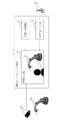
- FIG. 1 shows a functional block diagram of the image interface device 1 according to the first embodiment.
- the image interface device 1 includes an image display unit 11, a substitute body drawing unit 14, and an operation signal input unit 15.
- the image display unit 11 is a display that displays moving images such as a liquid crystal display, a video projector, and a head-mounted display.
- the image display unit 11 displays an image 10 of an operation target operated by the user 12.
- the virtual substitute body 13 of the user 12 is drawn on the image display unit 11 by the substitute body drawing unit 14.
- the image 10 of the operation object displayed on the image display unit 11 is a subjective image seen from the surrogate body 13. That is, the image 10 of the operation target object is displayed as an image seen from the eyes of the surrogate body 13 drawn on the image display unit 11.
- the image 10 of the operation object may be a real image of the remote operation object taken by a camera or the like, or may be a virtual image of a simulator, a game, or the like.
- the operation target is not limited to this, and the operation target may be any object to be operated by the user, such as a humanoid robot, a vehicle, or a medical device.
- the surrogate body drawing unit 14 draws the virtual surrogate body 13 of the user 12 on the image display unit 11.
- the operation signal input unit 15 is input with an operation signal from the user 12 for the operation target object.
- the operation signal input to the operation signal input unit 15 is transmitted to the image display unit 11.
- the image 10 of the operation target displayed on the image display unit 11 is operated by this operation signal.
- the surrogate body 13 virtually substitutes for the body of the user 12, and is drawn on the image display unit 11 by the surrogate body drawing unit 14 as described above. That is, when viewed from the user 12 who operates the image interface device 1, the surrogate body 13 behaves like his own alter ego on the image display unit 11.
- the surrogate body 13 may be a concrete image similar to the body of the user 12, or may be an abstract image such as a silhouette, a line art, or a translucent image.
- the size of the surrogate body 13 is variable according to the size of the object to be operated. Typically, the larger the operation target object is drawn as a larger body, and the smaller the operation target object is drawn as a smaller body.
- the surrogate body 13 is drawn as having substantially the same size as the operation target. For example, when the operation target is a heavy machine, the surrogate body 13 is drawn as a "giant" having substantially the same size as the heavy machine. On the contrary, when the operation target is a micromachine, the surrogate body 13 is drawn as a "dwarf" having almost the same size as the micromachine.
- the image 10 of the operation object displayed on the image display unit 11 is a subjective image seen from the surrogate body 13. As a result, the user can operate the image 10 of the operation object displayed on the image display unit 11 from the position of the surrogate body 13 having a size corresponding to the size of the operation object.
- the size of the micromachine is too large for the user as it is, so the minute movement of the micromachine and the movement of the hand are greatly different, and the user feels that it is difficult to operate as desired. ..
- a surrogate body of the same size as the micromachine on the screen and operating the micromachine from the standpoint of this surrogate body, it seems that the fine movement of the micromachine matches the movement of one's hand. , It is possible to operate without discomfort.
- the surrogate body 13 may have a plurality of sizes. At this time, the size of the surrogate body 13 may be dynamically switchable with respect to the operation target.
- the surrogate body 13 may have various sizes for one operation object depending on the intended use and the situation.
- the surrogate body 13 is a "very large giant” with a height of 10 m, a “giant” with a height approximately the same as the heavy machine, a “small giant” with a height of 4 m, and a height. It may be drawn as having four heights, such as a "human” in the 1 m range.
- the surrogate body 13 is drawn as a "human”, a highly accurate operation feeling can be obtained, although there is a sense of discomfort due to the difference in scale between the surrogate body 13 and the operation object.
- the surrogate body 13 is drawn as a "very large giant”, a feeling of operation on a large scale can be obtained, although there is a sense of discomfort due to the surrogate body 13 being larger than the operation target.
- the surrogate body 13 is given a plurality of sizes, and the plurality of sizes are dynamically switched, so that the user can use the operation, the purpose, and the situation in which the operation target is placed.
- the size of the surrogate body 13 can be made accurate according to one's taste and the like.
- the surrogate body 13 When the surrogate body 13 has a plurality of sizes and this size can be dynamically switched with respect to the operation target object, the surrogate body 13 may have a plurality of positions with respect to the operation target object. At this time, the position of the surrogate body 13 may be dynamically switchable according to the size of the surrogate body 13.
- the surrogate body 13 should be positioned with respect to the operation target depends on the size of the surrogate body 13.
- the surrogate body 13 when the surrogate body 13 has the sizes of "very large giant”, “giant”, “small giant”, and “human”, the surrogate body 13 is an operation target in each size. It may have a plurality of height positions in the range from the top to the bottom of the.
- the surrogate body 13 when the surrogate body 13 is drawn as a "giant”, since the surrogate body 13 and the operation target are substantially the same size, the height position of the surrogate body 13 may be substantially the same as the operation target.
- the center position of the surrogate body 13 is matched with the operation position of the operation target (the tip of the arm, the end effector of the robot, etc.) to achieve higher accuracy. High operation can be realized.
- the surrogate body 13 is provided with a plurality of positions with respect to the operation target object, and the plurality of positions are dynamically switched, so that the user accurately positions the surrogate body 13 according to the size of the surrogate body. be able to.
- the position of the surrogate body 13 may be variable depending on the position of the object to be operated.
- a user operates an operation object displayed on the screen, he / she feels uncomfortable if he / she is positioned in an inappropriate place with respect to the operation object on the screen.
- the operation object is located near a wall, the user does not operate from a narrow place such that the operation object is sandwiched between the wall.
- the surrogate body 13 by locating the surrogate body 13 at a position that is easy for the user to operate according to the position of the operation target object, the operation can be performed without discomfort for the user.
- the surrogate body 13 may move on the image display unit together with the operation performed on the image 10 of the operation target object.
- the movement speed of the surrogate body 13 may be variable according to the movement speed of the operation target object.
- the surrogate body 13 is drawn so that the larger the operation object is, the slower the movement is, and the smaller the operation object is, the faster the movement is drawn.
- the arm of the heavy equipment is manually moved on the image display unit as described above, the user feels that the movement speed of his / her hand is too fast as it is.
- the user manually moves the micromachine on the image display unit the user feels that the movement speed of his / her hand is too slow compared to the movement speed of the micromachine as it is.
- the hand of the surrogate body 13 drawn on the image display unit moves quickly in response to the movement of the micromachine, the user can operate the micromachine without discomfort.
- the surrogate body 13 may have a variable position and orientation with respect to the object to be operated.
- the surrogate body 13 may be drawn so as to be located in front of, behind, left, right, above or below the operation target. In this case, the user feels that the operation object is operated from the front, the back, the left, the right, the top, and the bottom, respectively.
- the surrogate body 13 is drawn so that the position and orientation with respect to the heavy machine are appropriate, the user can operate the heavy machine without discomfort.
- the surrogate body 13 may continuously change the size. For example, consider the case where there is a huge first operation object such as a heavy machine and a small second operation object such as a robot that performs fine electrical wiring. The user operates the first operation object to lift and move the automobile, and then promptly operates the second operation object to perform the electrical wiring work in the engine room of the automobile. At this time, the surrogate body 13 is a "giant" while the user is operating the first operation object, and when the user starts the operation of the second operation object, the surrogate body 13 is continuously "small”. Transform into a "person". As a result, when the operation objects of different sizes are continuously switched and operated, the user naturally performs the operation as if he / she continuously transferred to the body of the optimum size for the operation of these operation objects. Can be done.
- the surrogate body 13 may continuously change its size. For example, consider the case where there is a robot having a first arm having a large size and coarse motion accuracy and a second arm having a small size and precise motion accuracy. That is, this robot has two parts having different sizes and operating accuracy. The user operates the first arm of the robot to move the precision equipment, and then promptly operates the second arm to repair the precision equipment. At this time, the surrogate body 13 is a "human" while the user is operating the first arm, and when the user starts operating the second arm, the surrogate body 13 is continuously transformed into a "dwarf". To do. As a result, when multiple parts with different sizes and operating accuracy of the operation target are continuously switched and operated, the user naturally moves to a body of the optimum size for operating these parts. Can be operated on.
- the image 10 of the operation object displayed on the image display unit 11 may be a mixture of the image components of the operation object seen from the surrogate bodies of two different sizes.
- it may be a mixture of an image component of a large operating object viewed from a large surrogate body and an image component of a small operating object viewed from a small surrogate body.
- the user can instantly switch and view each image by switching the consciousness of which image to view.
- the image of the operation target can be displayed on the image display unit. Since the image displayed at this time is a subjective image seen from the virtual body, the user can operate it without discomfort.
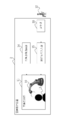
- FIG. 2 shows a functional block diagram of the image interface device 1 according to the second embodiment.
- the image interface device 1 includes an image display unit 11 that displays an image 10 of an operation object 110 operated by the user 12, and a surrogate body drawing unit 14 that draws a virtual surrogate body 13 of the user 12 on the image display unit 11.
- the operation signal input unit 15 for inputting the operation signal from the user 12 to the operation object 110 is provided.
- the image 10 of the operation object 110 is an image taken by a camera 100 installed in the vicinity of the operation object 110. That is, this embodiment is different from the more general first embodiment in that the image of the operation target 110 is an image taken by the camera 100. Other configurations and operations are common to the first embodiment.
- the camera 100 is, for example, a video camera.
- the camera 100 is arranged in the vicinity of the operation target 110.
- the image taken by the camera 100 is almost the same as the scenery seen from the surrogate body 13. In this sense, the camera 100 shares a viewpoint with the surrogate body 13.
- the camera 100 transmits the captured image to the image display unit 11.
- the image display unit 11 displays an image received from the camera 100.
- an actual operation target can be displayed on the image display unit. Since the image displayed at this time is a subjective image seen from the virtual body, the user can operate it without discomfort.
- FIG. 3 shows a functional block diagram of the image manipulation device 2 according to the third embodiment.
- the image operating device 2 includes an image display unit 11 that displays an image 10 of an operation object 110 operated by the user 12, and a surrogate body drawing unit 14 that draws a virtual surrogate body 13 of the user 12 on the image display unit 11.
- the operation signal input unit 15 for inputting the operation signal from the user 12 to the operation object 110, and the operation unit 20 are provided. That is, in this embodiment, the operation unit 20 is added to the image interface device of FIG.
- the operation unit 20 generates an operation signal by being operated by the user 12.
- the operation unit 20 is, for example, a motion controller held in the hand of the user 12. Not limited to this, the operation unit 20 may be any suitable controller such as a mouse, a joystick, and a game pad.
- the user 12 operates the operation unit 20 in order to operate the image 10 while looking at the image 10 of the operation target displayed on the image display unit 11.
- the operation unit 20 generates an operation signal that determines the operation of the image 10.
- the operation unit 20 transmits the generated operation signal to the operation signal input unit 15.
- the operation signal input unit 15 transmits the operation signal to the image display unit 11.
- the image 10 of the operation object may be an image of a remote operation object taken by a camera or the like, or may be a virtual image of a simulator, a game, or the like.
- the user can operate this image on the screen without discomfort while looking at the image of the operation object displayed on the image display unit.
- FIG. 4 shows a functional block diagram of the operation object operation device 3 according to the fourth embodiment.
- the operation object operation device 3 includes an image display unit 11 that displays an image 10 of the operation object 110 operated by the user 12, and a substitute body drawing unit that draws a virtual substitute body 13 of the user 12 on the image display unit 11.
- the operation signal input unit 15, the operation unit 20, and the operation signal output unit 30 for inputting the operation signal from the user 12 to the operation object 110 are provided. That is, in this embodiment, the operation signal output unit 30 is added to the image operation device 2 of FIG.
- the operation signal output unit 30 receives the operation signal from the user 12 from the image display unit 11. The operation signal output unit 30 outputs this operation signal to the operation object 110.
- the user 12 operates the operation unit 20 in order to operate the remote operation object 110 while looking at the image 10 of the operation object 110 displayed on the image display unit 11.
- the operation unit 20 generates an operation signal that determines the operation of the operation object 110.
- the operation unit 20 transmits the generated operation signal to the operation signal input unit 15.
- the operation signal input unit 15 transmits the operation signal to the image display unit 11.
- the image display unit 11 transmits an operation signal to the operation signal output unit 30.
- the operation signal output unit 30 outputs the operation signal to the operation object 110.
- the user can remotely operate the operation object without discomfort while viewing the image of the operation object displayed on the image display unit.
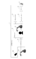
- FIG. 5 shows a functional block diagram of the operation object operation system 4 according to the fifth embodiment.
- the operation object operation system 4 includes an image display unit 11 that displays an image 10 of the operation object 110 operated by the user 12, and a substitute body drawing unit that draws a virtual substitute body 13 of the user 12 on the image display unit 11. It includes an operation signal input unit 15, an operation signal input unit 15, an operation signal output unit 30, and a camera 100 into which an operation signal from the user 12 for the operation object 110 is input. That is, in this embodiment, the camera 100 is added to the operation object operation device 3 of FIG.
- the camera 100 is, for example, a video camera, and is arranged in the vicinity of the operation target 110.
- the image taken by the camera 100 is almost the same as the scenery seen from the surrogate body 13. In this sense, the camera 100 shares a viewpoint with the surrogate body 13.
- the camera 100 transmits the captured image to the image display unit 11.
- the image display unit 11 displays an image received from the camera 100.
- the user can remotely operate the operation object without discomfort while viewing the image of the actual operation object taken by the camera provided in this system.
- the camera 100 may include a moving mechanism for changing the position.
- the moving mechanism moves the position of the camera 100 with respect to the operation target 110 by, for example, a motor.
- the camera 100 can photograph the operation object 110 from, for example, front, rear, left, right, top or bottom. Therefore, the subjective image seen from the surrogate body 13 is also a view of the operation object 110 from the front, the back, the left, the right, the top, or the bottom.
- the camera 100 may include a rotation mechanism for changing the shooting direction.
- the rotation mechanism rotates the camera 100 around a predetermined axis by, for example, a motor. Rotation around the axis corresponds to, for example, rolling, pitching, yawing, etc. of the camera.
- the camera 100 can photograph the operation object 110 from various angles. Therefore, the subjective image seen from the surrogate body 13 also looks at the operation object 110 from various angles.
- the moving or rotating mechanism of the camera 100 may move the camera in a direction opposite to the user's operating direction.
- the image displayed on the image display unit may be an inverted image of the image taken by the camera 100.
- the user sees the scenery seen from the surrogate body on the image display unit 11 and the left and right sides are reversed from the actual scenery.
- the user operates the operation object in the direction opposite to the direction of the operation performed by the user. In other words, the user feels as if he / she is operating an object to be operated in a world that is opposite to the actual world.
- the right hand when a right-handed user wants to approach from the right side with his / her right hand as his / her physical sensation, but can approach only from the left side due to the environment in which the object to be operated is placed, the right hand is used. It can be operated without any discomfort.
- the camera 100 may be a stereo camera with two cameras.
- the image of the operation object 110 taken by the camera 100 is three-dimensional and has a sense of depth for the user.
- the intereye distance of the stereo camera may be variable depending on the size of the surrogate body 13.
- the camera 100 may be provided with an inter-eye distance adjusting mechanism for dynamically adjusting the inter-eye distance using a motor or the like.
- the interocular distance of the stereo camera is adjusted longer as the surrogate body 13 is larger, and shorter as the surrogate body 13 is smaller.
- the inter-eye distance of the stereo camera is adjusted according to the size of the surrogate body 13, the user can see an image having a more natural sense of depth for each operation target 110.
- the camera 100 may be a depth camera that detects the distance to the operation target 110 in real time.
- the image of the operation target 110 taken by the camera 100 can provide a more realistic sense of depth and immersiveness for the user.
- the camera 100 may include a plurality of cameras that capture different fields of view. At this time, the images of the plurality of fields of view taken by the plurality of cameras may be displayed at the same time, or may be switched by the user and displayed separately. In this embodiment, the user can see the operation object 110 as viewed from a plurality of viewpoints of the surrogate body 13.
- FIG. 6 is a flowchart showing a processing procedure of the operation object presentation method according to the sixth embodiment.
- Step S1 is a process of acquiring information on the size of the operation target to be presented.
- the size information may be acquired in real time by a camera or the like, or may be acquired from data stored in a database or the like in advance.
- the size of the object to be operated is arbitrary, but for example, it is several tens of m for a construction machine and several mm for a micromachine.
- Step S2 is a process of drawing a surrogate body on the image display unit according to the size of the operation object.
- This surrogate body virtually represents the user's body. This may be a concrete image similar to the user's body, or an abstract image such as a silhouette, a line art, or a translucent image.
- the size of the surrogate body is variable depending on the size of the object to be operated. Typically, the larger the operation object is drawn as a larger body, and the smaller the operation object is, the smaller the body is drawn. For example, the surrogate body is drawn as being substantially the same size as the object to be manipulated.
- the process proceeds to step S3.
- Step S3 is a process of displaying an image of the operation object on the image display unit as a subjective image of the surrogate body. That is, the image of the operation object is displayed as an image seen from the eyes of the surrogate body drawn on the image display unit.
- the image of the operation object may be a real image of the remote operation object taken by a camera or the like, or may be a virtual image of a simulator, a game, or the like.
- the operation target can be presented to the user. Since the image presented at this time is a subjective image seen from the virtual body, the user can operate it without discomfort.
- a seventh embodiment is an operation object presentation program.
- This program includes a step S1 for displaying an image of an operation object operated by the user on the image display unit, a step S2 for drawing a virtual surrogate body of the user on the image display unit, and an operation target based on an operation signal from the user.
- the operation target can be presented to the user using a computer. Since the image presented at this time is a subjective image seen from the virtual body, the user can operate it without discomfort.
- the moving mechanism and the rotating mechanism of the camera of the embodiment may be operated by using the head-mounted display.
- the head-mounted display transmits a signal for operating the moving mechanism and the rotating mechanism of the camera to the moving mechanism and the rotating mechanism.
- This signal is for moving the shooting position and direction of the camera in conjunction with the movement of the user's head.
- the user can freely operate the shooting position and direction of the operation target by the movement of the head.
- the operating object operating device of the embodiment may include a microphone in the vicinity of the operating object.
- the sound collected by the microphone is transmitted to the user as a sound heard by the surrogate body.
- the user operates the operation target while viewing the image displayed on the image display unit and listening to the sound collected by the microphone.
- the user can share hearing with the surrogate body in addition to the viewpoint. As a result, the user can operate the operation object with a more natural feeling.
- the present invention covers a wide range of applications such as remote control of construction machinery, surgical support, operation of humanoid robots, operation of vehicles, simulators, and games.
- the method according to the present invention can be used for such various applications.
Landscapes
- Engineering & Computer Science (AREA)
- General Engineering & Computer Science (AREA)
- Theoretical Computer Science (AREA)
- Human Computer Interaction (AREA)
- Physics & Mathematics (AREA)
- General Physics & Mathematics (AREA)
- User Interface Of Digital Computer (AREA)
- Manipulator (AREA)
- Processing Or Creating Images (AREA)
Abstract
ユーザが操作する操作対象物の画像を表示する画像表示部と、画像表示部にユーザの仮想的な代理身体を描画する代理身体描画部と、操作対象物に対するユーザからの操作信号が入力される操作信号入力部と、を備える画像インタフェース装置。代理身体の大きさは操作対象物の大きさに応じて可変であり、画像表示部に表示される操作対象物の画像は代理身体から見た主観画像である。画像操作装置は、この画像インタフェース装置に加えてユーザが操作することにより操作信号を生成する操作部を備える。
Description
本発明は、画像インタフェース装置、画像操作装置、操作対象物操作装置、操作対象物操作システム、操作対象物提示方法および操作対象物提示プログラムに関する。
遠隔ロボットをあたかもユーザの手元にあるかのようなものとして制御する技術に、テレイグジスタンスがある(例えば、非特許文献1参照)。
"Telecommunication、Teleimmersion and Telexistence II" Susumu Tachi、Ohmsha、IOS Press、ISBN 4-274-90638-8(Ohmsha)ISBN 1-58603-519-3
テレイグジスタンスは、遠隔にあるロボットに設置したセンサ等から得た情報に基づいて、該ロボットを制御、操縦する技術である。テレイグジスタンスでは、ロボットの動作がユーザの身体動作にマッピングされるため、ユーザはロボットに「憑依」して操作しているような感覚を得る。これによりユーザは、遠隔地にあるものをあたかも身近にあるかのように感じながらロボットを操作することができる。
しかしながら従来のテレイグジスタンスでは、ロボットのサイズに対するユーザのサイズは、予め定められたものとして固定されている。このためロボットのサイズ、動作または位置などがロボットごとに変わったような場合、ユーザはこれに対応して違和感なくロボットを操作することができない。
本発明はこうした状況に鑑みてなされたものであり、その目的は、多様なサイズ、位置、動作または運動特性を持つロボット等の操作対象物を、違和感なく操作できる技術を提供することにある。
上記課題を解決するために、本発明のある態様の画像インタフェース装置は、ユーザが操作する操作対象物の画像を表示する画像表示部と、画像表示部にユーザの仮想的な代理身体を描画する代理身体描画部と、操作対象物に対するユーザからの操作信号が入力される操作信号入力部と、を備える。代理身体の大きさは、操作対象物の大きさに応じて可変である。画像表示部に表示される操作対象物の画像は、代理身体から見た主観画像である。
実施の形態の代理身体は複数の大きさを有し、これら複数の大きさは前記操作対象物に対して動的に切替可能であってよい。
実施の形態の代理身体は操作対象物に対する複数の位置を有し、これら複数の位置は動的に切替可能であってよい。
実施の形態の代理身体の位置は、操作対象物の位置に応じて可変であってよい。
実施の形態の代理身体は、操作対象物の画像に対してなされる操作とともに画像表示部上で運動してもよい。このとき代理身体の画像表示部上での運動速度は、操作対象物の運動速度に応じて可変であってもよい。
実施の形態の代理身体は、操作対象物に対する位置または向きが可変であってもよい。
実施の形態の操作対象物は大きさの異なる複数の操作対象物を含んでもよい。このとき、複数の操作対象物が連続的に切り替えて操作されるとき、代理身体の大きさは連続的に可変であってもよい。
実施の形態の代理身体は、2つの異なる大きさの代理身体を含んでもよい。このとき、画像表示部に表示される操作対象物の画像は、2つの異なる大きさの代理身体から見た操作対象物の画像成分を混合したものであってもよい。
実施の形態の操作対象物の画像は、操作対象物の近辺に設置されたカメラによって撮影された画像であってもよい。
本発明の別の態様は、画像操作装置である。この画像操作装置は、ユーザが操作する操作対象物の画像を表示する画像表示部と、画像表示部にユーザの仮想的な代理身体を描画する代理身体描画部と、操作対象物に対するユーザからの操作信号が入力される操作信号入力部と、ユーザが操作することにより操作信号を生成する操作部と、を備える。代理身体の大きさは、操作対象物の大きさに応じて可変である。画像表示部に表示される操作対象物の画像は、代理身体から見た主観画像である。
実施の形態の代理身体は複数の大きさを有し、これら複数の大きさは前記操作対象物に対して動的に切替可能であってよい。
実施の形態の代理身体は操作対象物に対する複数の位置を有し、これら複数の位置は動的に切替可能であってよい。
本発明のさらに別の態様は、操作対象物操作装置である。この操作対象物操作装置は、ユーザが操作する操作対象物の画像を表示する画像表示部と、画像表示部にユーザの仮想的な代理身体を描画する代理身体描画部と、操作対象物に対するユーザからの操作信号が入力される操作信号入力部と、ユーザが操作することにより操作信号を生成する操作部と、ユーザの操作信号を操作対象物に出力する操作信号出力部と、を備える。代理身体の大きさは、操作対象物の大きさに応じて可変である。画像表示部に表示される操作対象物の画像は、代理身体から見た主観画像である。
本発明のさらに別の態様は、操作対象物操作システムである。この操作対象物操作システムは、ユーザが操作する操作対象物の画像を表示する画像表示部と、画像表示部にユーザの仮想的な代理身体を描画する代理身体描画部と、操作対象物に対するユーザからの操作信号が入力される操作信号入力部と、ユーザが操作することにより操作信号を生成する操作部と、ユーザの操作信号を操作対象物に出力する操作信号出力部と、操作対象物を撮影するカメラと、を備える。代理身体の大きさは、操作対象物の大きさに応じて可変である。画像表示部に表示される操作対象物の画像は、代理身体から見た主観画像である。
実施の形態の代理身体は複数の大きさを有し、これら複数の大きさは前記操作対象物に対して動的に切替可能であってよい。
実施の形態の代理身体は操作対象物に対する複数の位置を有し、これら複数の位置は動的に切替可能であってよい。
実施の形態のカメラは、位置を変えるための移動機構を備えてもよい。
実施の形態のカメラは、撮影方向を変えるための回転機構を備えてもよい。
実施の形態のカメラの移動機構と回転機構は、ユーザの操作方向と反対方向にカメラを動かし、画像表示部に表示される画像は、カメラが撮影した画像の左右を反転させたものであってもよい。
実施の形態のカメラは、2つのカメラを備えたステレオカメラであってもよい。
実施の形態のステレオカメラの眼間距離は、代理身体の大きさに応じて可変であってもよい。
実施の形態のカメラは、操作対象物までの距離をリアルタイムに検知する深度カメラであってよい。
実施の形態のカメラは、それぞれ異なる視野を撮影する複数のカメラを備えてよい。
本発明のさらに別の態様は、操作対象物提示方法である。この方法は、操作対象物の大きさの情報を取得するステップと、ユーザの仮想的な代理身体を描画するステップと、操作対象物の画像を表示するステップと、を備える。代理身体の大きさは操作対象物の大きさに応じて可変である。操作対象物の画像は代理身体から見た主観画像である。
実施の形態の代理身体は複数の大きさを有し、これら複数の大きさは前記操作対象物に対して動的に切替可能であってよい。
実施の形態の代理身体は操作対象物に対する複数の位置を有し、これら複数の位置は動的に切替可能であってよい。
本発明のさらに別の態様は、操作対象物提示プログラムである。このプログラムは、操作対象物の大きさの情報を取得するステップと、ユーザの仮想的な代理身体を描画するステップと、操作対象物の画像を表示するステップと、をコンピュータに実行させる。代理身体の大きさは操作対象物の大きさに応じて可変である。操作対象物の画像は代理身体から見た主観画像である。
実施の形態の代理身体は複数の大きさを有し、これら複数の大きさは前記操作対象物に対して動的に切替可能であってよい。
実施の形態の代理身体は操作対象物に対する複数の位置を有し、これら複数の位置は動的に切替可能であってよい。
なお、以上の構成要素の任意の組合せ、本発明の表現を装置、方法、システム、記録媒体、コンピュータプログラムなどの間で変換したものもまた、本発明の態様として有効である。
本発明によれば、多様なサイズや運動特性を持つロボットなどの操作対象物を違和感なく操作可能な画像を画面上に提示することができる。
以下、本発明を好適な実施の形態をもとに図面を参照しながら説明する。実施の形態は、発明を限定するものではなく例示である。実施の形態に記述されるすべての特徴やその組み合わせは、必ずしも発明の本質的なものであるとは限らない。各図面に示される同一または同等の構成要素、部材、処理には、同一の符号を付するものとし、適宜重複した説明は省略する。また、各図に示す各部の縮尺や形状は、説明を容易にするために便宜的に設定されており、特に言及がない限り限定的に解釈されるものではない。また、本明細書または請求項の中で「第1」、「第2」等の用語が用いられる場合、特に言及がない限りこの用語はいかなる順序や重要度を表すものでもなく、ある構成と他の構成とを区別するだけのためのものである。また、各図面において実施の形態を説明する上で重要ではない部材の一部は省略して表示する。
[第1の実施の形態]
図1に、第1の実施の形態に係る画像インタフェース装置1の機能ブロック図を示す。画像インタフェース装置1は、画像表示部11と、代理身体描画部14と、操作信号入力部15と、を備える。
図1に、第1の実施の形態に係る画像インタフェース装置1の機能ブロック図を示す。画像インタフェース装置1は、画像表示部11と、代理身体描画部14と、操作信号入力部15と、を備える。
画像表示部11は、例えば液晶ディスプレイ、ビデオプロジェクタ、ヘッドマウントディスプレイといった動画像を表示するディスプレイである。画像表示部11には、ユーザ12が操作する操作対象物の画像10が表示される。さらに画像表示部11には、代理身体描画部14によって、ユーザ12の仮想的な代理身体13が描画される。画像表示部11に表示される操作対象物の画像10は、代理身体13から見た主観画像である。すなわち操作対象物の画像10は、画像表示部11に描画された代理身体13の目から見た画像として表示される。操作対象物の画像10は、カメラなどによって撮影された遠隔の操作対象物の実画像であってもよいし、シミュレータやゲームなどの仮想的な画像であってもよい。以下、主に建設機械などの産業用ロボットを操作対象物の例として説明する。しかしこれに限られず、操作対象物は、人型ロボット、乗り物、医療用器具など、ユーザの操作の対象になるものであれば何であってもよい。
代理身体描画部14は、画像表示部11にユーザ12の仮想的な代理身体13を描画する。
操作信号入力部15には、操作対象物に対するユーザ12からの操作信号が入力される。操作信号入力部15に入力された操作信号は、画像表示部11に送信される。画像表示部11に表示された操作対象物の画像10は、この操作信号によって操作される。
代理身体13は、ユーザ12の身体を仮想的に代理するものであり、前述のように代理身体描画部14によって画像表示部11に描画される。すなわち、画像インタフェース装置1を操作するユーザ12から見たとき、代理身体13は画像表示部11上で自分の分身のように振る舞う。代理身体13は、ユーザ12の身体に類似した具象的な画像であってもよいし、シルエット、線画、半透明画像といった抽象的な画像であってもよい。
代理身体13の大きさは、操作対象物の大きさに応じて可変である。典型的には代理身体13は、操作対象物が大きければ大きいほど大きな身体として描画され、操作対象物が小さければ小さいほど小さな身体として描画される。例えば代理身体13は、操作対象物の大きさと実質的に同じ大きさのものとして描画される。例えば操作対象物が重機である場合、代理身体13は当該重機とほぼ同じ大きさの「巨人」として描画される。逆に操作対象物がマイクロマシンである場合、代理身体13は当該マイクロマシンとほぼ同じ大きさの「小人」として描画される。前述のように、画像表示部11に表示される操作対象物の画像10は代理身体13から見た主観画像である。これによりユーザは、操作対象物の大きさに応じた大きさを持つ代理身体13の立場で、画像表示部11に表示された操作対象物の画像10を操作することができる。
一般にユーザが画面に表示された操作対象物を操作する場合、画面上の操作対象物と自分の大きさとが異なっていると、ユーザは操作に違和感を覚える。例えば画面上で重機のアームを手で動かす操作をしたとき、そのままでは重機に対する自分のサイズが小さすぎるため、アームの可動域と自分の腕の可動域とが大きく異なり、ユーザは思い通りの操作がしにくいと感じる。これに対し、画面上に重機と同じサイズの代理身体を配置し、この代理身体の立場で重機を操作することにより、アームの可動域と自分の腕の可動域とが一致するように感じられ、違和感のない操作が可能となる。逆に例えば画面上でマイクロマシンを手で操作したとき、そのままではマイクロマシンに対する自分のサイズが大きすぎるため、マイクロマシンの微細な動きと手の動きとが大きく異なり、ユーザは思い通りの操作がしにくいと感じる。これに対し、画面上にマイクロマシンと同じサイズの代理身体を配置し、この代理身体の立場でマイクロマシンを操作することにより、マイクロマシンの精細な動きと自分の手の動きとが一致するように感じられ、違和感のない操作が可能となる。
ある実施の形態では、代理身体13は複数の大きさを有してもよい。このとき代理身体13の大きさは、操作対象物に対して動的に切替可能であってよい。上記の説明では、代理身体13の典型的な例として、操作対象物が大きければ大きいほど大きな身体として描画され、操作対象物が小さければ小さいほど小さな身体として描画されるものを示した。しかしこれに限られず、代理身体13は、1つの操作対象物に対し、用途や状況に応じて様々な大きさを持つものであってもよい。例えば操作対象物高さ6mの重機である場合、代理身体13は、身長10mの「非常に大きな巨人」、当該重機とほぼ同じ大きさの「巨人」、身長4mの「小さめの巨人」、身長1m台の「人間」といったように、4つの身長を持つものとして描画されてもよい。
上記の例で代理身体13が「巨人」として描画された場合、代理身体13と操作対象物とがほぼ同じスケールとなるので、ユーザは違和感を覚えることがない。その一方で、操作対象物は「巨人」によって操作される結果、操作の精度は粗いものとなる。次に代理身体13が「小さめの巨人」として描画された場合、代理身体13と操作対象物のスケールが大きく違わないため、一定程度違和感が改善されつつ、精度の低下も抑制された操作感が得られる。次に代理身体13が「人間」として描画された場合、代理身体13と操作対象物のスケールの違いによる違和感はあるものの、高い精度の操作感が得られる。最後に代理身体13が「非常に大きな巨人」として描画された場合、代理身体13が操作対象より大きいことによる違和感はあるものの、大きなスケールでの操作感が得られる。このように、代理身体13に複数の大きさを持たせ、この複数の大きさを動的に切り替えることにより、ユーザは、操作の用途や目的、操作対象物の置かれた状況。自分の好みなどに応じて、代理身体13の大きさを的確なものとすることができる。
代理身体13が複数の大きさを有し、この大きさが操作対象物に対して動的に切替可能である場合、代理身体13は、操作対象物に対する複数の位置を有してもよい。このとき代理身体13の位置は、代理身体13の大きさに応じて動的に切替可能であってよい。
一般に、操作対象物に対して代理身体13をどこに位置付ければよいかは、代理身体13の大きさによる。特に代理身体13と操作対象物の大きさが異なるほど、代理身体13の操作対象物に対する位置は重要となる。例えば上記の例で代理身体13が「非常に大きな巨人」「巨人」「小さめの巨人」「人間」の大きさを有する場合、この代理身体13は、それぞれのそれぞれの大きさにおいて、操作対象物の最上部から最下部までの範囲で複数の高さ位置を有してよい。ここで代理身体13が「巨人」として描画された場合、代理身体13と操作対象物はほぼ同じサイズであるため、代理身体13の高さ位置は概ね操作対象物と一致していればよい。ここで代理身体13の大きさが「人間」に切り替わった場合、代理身体13の中心位置を操作対象物の操作位置(アームの先端や、ロボットのエンドエフェクタ等)に一致させることにより、より精度の高い操作を実現することができる。
このように、代理身体13に操作対象物に対する複数の位置を持たせ、この複数の位置を動的に切り替えることにより、ユーザは、代理身体の大きさに応じて、代理身体13を的確に位置付けることができる。
このように、代理身体13に操作対象物に対する複数の位置を持たせ、この複数の位置を動的に切り替えることにより、ユーザは、代理身体の大きさに応じて、代理身体13を的確に位置付けることができる。
ある実施の形態では、代理身体13の位置は、操作対象物の位置に応じて可変であってよい。一般にユーザが画面に表示された操作対象物を操作する場合、画面上の操作対象物に対して自分が適切でないところ位置すると違和感を覚える。例えば、操作対象物が壁際に位置するようなとき、ユーザは操作対象物と壁とに挟まれるような狭い場所からは操作しない。このような場合、操作対象物の位置に応じて、ユーザが操作しやすい位置に代理身体13を位置づけることにより、ユーザにとって違和感のない操作が可能となる。
ある実施の形態では、代理身体13は、操作対象物の画像10に対してなされる操作とともに画像表示部上で運動してもよい。このとき代理身体13の運動速度は、操作対象物の運動速度に応じて可変であってもよい。典型的には代理身体13は、操作対象物が大きければ大きいほどゆっくり動くように描画され、操作対象物が小さければ小さいほど速く動くように描画される。前述と同様に画像表示部上で重機のアームを手で動かす操作をしたとき、ユーザはそのままでは、アームの運動速度に比べて自分の手の運動速度が速すぎると感じる。同様に、画像表示部上でマイクロマシンを手で動かす操作をしたとき、ユーザはそのままでは、マイクロマシンの運動速度に比べて自分の手の運動速度が遅すぎると感じる。これに対し、画像表示部上に描画された代理身体13の手が、マイクロマシンの動きに対応して素早く動くようにすれば、ユーザは違和感なくマイクロマシンを操作することができる。
ある実施の形態では、代理身体13は、操作対象物に対する位置や向きが可変であってもよい。例えば代理身体13は、操作対象物の前、後、左、右、上または下に位置するように描画されてよい。この場合ユーザは、この操作対象物をそれぞれ前、後、左、右、上、下から操作するように感じる。例えばユーザが画像表示部上で重機のアームを手で動かす操作をするとき、重機の姿勢や運動方向に応じて、重機に対してどの位置からどの向きで操作すれば自然であるかが異なる。従って、重機に対する自分の位置や向きが固定的であると、操作が不自然だと感じられる場合がある。これに対し、重機に対する位置や向きが適当であるように代理身体13が描画されれば、ユーザは違和感なく重機を操作することができる。
ある実施の形態では、大きさの異なる複数の操作対象物が存在し、ユーザがこれらを連続的に切り替えて操作するとき、代理身体13はその大きさを連続的に変えてもよい。例えば、重機のような巨大な第1の操作対象物と、微細な電気配線を行うロボットのような小さな第2の操作対象物とがある場合を考える。ユーザは、第1の操作対象物を操作して自動車を持ち上げて移動した後、速やかに第2の操作対象物を操作して自動車のエンジンルーム内の電気配線作業を行うものとする。このとき、ユーザが第1の操作対象物を操作している間は代理身体13は「巨人」であり、ユーザが第2の操作対象物の操作を開始すると代理身体13は連続的に「小人」に変身する。これにより、大きさの異なる操作対象物を連続的に切り替えて操作するとき、ユーザはこれらの操作対象物の操作に最適なサイズの身体に連続的に乗り移ったかのように、自然に操作を行うことができる。
ある実施の形態では、操作対象物が複数の構成やパーツを有し、ユーザがこれらを連続的に切り替えて操作するとき、代理身体13はその大きさを連続的に変えてもよい。例えば、サイズが大きく動作精度が粗い第1の腕と、サイズが小さく動作精度が精密な第2の腕とを持つロボットがある場合を考える。すなわちこのロボットは、大きさや動作精度が異なる2つのパーツを有する。ユーザは、このロボットの第1の腕を操作して精密機器を移動した後、速やかに第2の腕を操作してこの精密機器を修理するものとする。このとき、ユーザが第1の腕を操作している間は代理身体13は「人間」であり、ユーザが第2の腕の操作を開始すると代理身体13は連続的に「小人」に変身する。これにより、操作対象物が持つ大きさや動作精度が異なる複数のパーツを連続的に切り替えて操作するとき、ユーザはこれらのパーツの操作に最適なサイズの身体に連続的に乗り移ったかのように、自然に操作を行うことができる。
ある実施の形態では、画像表示部11に表示される操作対象物の画像10は、2つの異なる大きさの代理身体から見た操作対象物の画像成分を混合したものであってよい。例えば、大きな代理身体から見た大きな操作対象物の画像成分と、小さな代理身体から見た小さな操作対象物の画像成分とを混合したものであってよい。この実施の形態によれば、ユーザは、どちらの画像を見るかの意識を切り替えることによって、それぞれの画像を瞬時に切り替えて見ることができる。
以上述べたように、これらの実施の形態によれば、操作対象物の画像を画像表示部に表示することができる。このとき表示される画像は仮想身体から見た主観画像なので、ユーザはこれを違和感なく操作することができる。
[第2の実施の形態]
図2に、第2の実施の形態に係る画像インタフェース装置1の機能ブロック図を示す。画像インタフェース装置1は、ユーザ12が操作する操作対象物110の画像10を表示する画像表示部11と、画像表示部11にユーザ12の仮想的な代理身体13を描画する代理身体描画部14と、操作対象物110に対するユーザ12からの操作信号が入力される操作信号入力部15と、を備える。操作対象物110の画像10は、操作対象物110の近辺に設置されたカメラ100によって撮影された画像である。すなわちこの実施の形態は、特に操作対象物110の画像がカメラ100によって撮影された画像であるという点で、より一般的な第1の実施の形態と異なる。その他の構成と動作は、第1の実施の形態と共通である。
図2に、第2の実施の形態に係る画像インタフェース装置1の機能ブロック図を示す。画像インタフェース装置1は、ユーザ12が操作する操作対象物110の画像10を表示する画像表示部11と、画像表示部11にユーザ12の仮想的な代理身体13を描画する代理身体描画部14と、操作対象物110に対するユーザ12からの操作信号が入力される操作信号入力部15と、を備える。操作対象物110の画像10は、操作対象物110の近辺に設置されたカメラ100によって撮影された画像である。すなわちこの実施の形態は、特に操作対象物110の画像がカメラ100によって撮影された画像であるという点で、より一般的な第1の実施の形態と異なる。その他の構成と動作は、第1の実施の形態と共通である。
カメラ100は、例えばビデオカメラである。カメラ100は操作対象物110の近辺に配置される。カメラ100が撮影した画像は、代理身体13から見た景色とほぼ同じものである。この意味でカメラ100は、代理身体13と視点を共有する。カメラ100は、撮影した画像を画像表示部11に送信する。画像表示部11は、カメラ100から受信した画像を表示する。
この実施の形態によれば、現実の操作対象物を画像表示部に表示することができる。このとき表示される画像は仮想身体から見た主観画像なので、ユーザはこれを違和感なく操作することができる。
[第3の実施の形態]
図3に、第3の実施の形態に係る画像操作装置2の機能ブロック図を示す。画像操作装置2は、ユーザ12が操作する操作対象物110の画像10を表示する画像表示部11と、画像表示部11にユーザ12の仮想的な代理身体13を描画する代理身体描画部14と、操作対象物110に対するユーザ12からの操作信号が入力される操作信号入力部15と、操作部20と、を備える。すなわちこの実施の形態は、図1の画像インタフェース装置に操作部20を追加したものである。
図3に、第3の実施の形態に係る画像操作装置2の機能ブロック図を示す。画像操作装置2は、ユーザ12が操作する操作対象物110の画像10を表示する画像表示部11と、画像表示部11にユーザ12の仮想的な代理身体13を描画する代理身体描画部14と、操作対象物110に対するユーザ12からの操作信号が入力される操作信号入力部15と、操作部20と、を備える。すなわちこの実施の形態は、図1の画像インタフェース装置に操作部20を追加したものである。
操作部20は、ユーザ12が操作することにより操作信号を生成する。操作部20は、例えばユーザ12の手に把持されるモーションコントローラである。これに限られず、操作部20は、マウス、ジョイスティック、ゲームパッドなどの任意の好適なコントローラであってよい。
ユーザ12は、画像表示部11に表示された操作対象物の画像10を見ながら、画像10を操作するために、操作部20を操作する。これにより操作部20は、画像10の動作を定める操作信号を生成する。操作部20は、生成した操作信号を操作信号入力部15に送信する。操作信号入力部15は、操作信号を画像表示部11に送信する。
操作対象物の画像10は、カメラなどによって撮影された遠隔の操作対象物の画像であってもよいし、シミュレータやゲームなどの仮想的な画像であってもよい。
この実施の形態によれば、ユーザは、画像表示部に表示された操作対象物の画像を見ながら、この画像を画面上で違和感なく操作することができる。
[第4の実施の形態]
図4に、第4の実施の形態に係る操作対象物操作装置3の機能ブロック図を示す。操作対象物操作装置3は、ユーザ12が操作する操作対象物110の画像10を表示する画像表示部11と、画像表示部11にユーザ12の仮想的な代理身体13を描画する代理身体描画部14と、操作対象物110に対するユーザ12からの操作信号が入力される操作信号入力部15と、操作部20と、操作信号出力部30と、を備える。すなわちこの実施の形態は、図3の画像操作装置2に操作信号出力部30を追加したものである。
図4に、第4の実施の形態に係る操作対象物操作装置3の機能ブロック図を示す。操作対象物操作装置3は、ユーザ12が操作する操作対象物110の画像10を表示する画像表示部11と、画像表示部11にユーザ12の仮想的な代理身体13を描画する代理身体描画部14と、操作対象物110に対するユーザ12からの操作信号が入力される操作信号入力部15と、操作部20と、操作信号出力部30と、を備える。すなわちこの実施の形態は、図3の画像操作装置2に操作信号出力部30を追加したものである。
操作信号出力部30は、ユーザ12からの操作信号を画像表示部11から受信する。
操作信号出力部30は、この操作信号を操作対象物110に出力する。
操作信号出力部30は、この操作信号を操作対象物110に出力する。
ユーザ12は、画像表示部11に表示された操作対象物110の画像10を見ながら、遠隔にある操作対象物110を操作するために、操作部20を操作する。これにより操作部20は、操作対象物110の動作を定める操作信号を生成する。操作部20は、生成した操作信号を操作信号入力部15に送信する。操作信号入力部15は、操作信号を画像表示部11に送信する。画像表示部11は、操作信号を操作信号出力部30に送信する。操作信号出力部30は、操作信号を操作対象物110に出力する。
この実施の形態によれば、ユーザは、画像表示部に表示された操作対象物の画像を見ながら、操作対象物を遠隔から違和感なく操作することができる。
[第5の実施の形態]
図5に、第5の実施の形態に係る操作対象物操作システム4の機能ブロック図を示す。操作対象物操作システム4は、ユーザ12が操作する操作対象物110の画像10を表示する画像表示部11と、画像表示部11にユーザ12の仮想的な代理身体13を描画する代理身体描画部14と、操作対象物110に対するユーザ12からの操作信号が入力される操作信号入力部15と、操作部20と、操作信号出力部30と、カメラ100と、を備える。すなわちこの実施の形態は、図4の操作対象物操作装置3にカメラ100を追加したものである。
図5に、第5の実施の形態に係る操作対象物操作システム4の機能ブロック図を示す。操作対象物操作システム4は、ユーザ12が操作する操作対象物110の画像10を表示する画像表示部11と、画像表示部11にユーザ12の仮想的な代理身体13を描画する代理身体描画部14と、操作対象物110に対するユーザ12からの操作信号が入力される操作信号入力部15と、操作部20と、操作信号出力部30と、カメラ100と、を備える。すなわちこの実施の形態は、図4の操作対象物操作装置3にカメラ100を追加したものである。
カメラ100は、例えばビデオカメラであり、操作対象物110の近辺に配置される。カメラ100が撮影した画像は、代理身体13から見た景色とほぼ同じものである。この意味でカメラ100は、代理身体13と視点を共有する。カメラ100は、撮影した画像を画像表示部11に送信する。画像表示部11は、カメラ100から受信した画像を表示する。
この実施の形態によれば、ユーザは、このシステムに備えられたカメラによって撮影された現実の操作対象物の画像を見ながら、操作対象物を遠隔から違和感なく操作することができる。
ある実施の形態では、カメラ100は、位置を変えるための移動機構を備えてもよい。移動機構は、例えばモータで操作対象物110に対するカメラ100の位置を移動する。これによりカメラ100は、例えば前、後、左、右、上または下から操作対象物110を撮影することができる。従って代理身体13から見た主観画像も、前、後、左、右、上または下から操作対象物110を見たものとなる。
ある実施の形態では、カメラ100は、撮影方向を変えるための回転機構を備えてもよい。回転機構は、例えばモータでカメラ100を所定の軸周りに回転させる。軸回りの回転は、例えばカメラのローリング、ピッチング、ヨーイングなどに相当する。これによりカメラ100は、様々な角度から操作対象物110を撮影することができる。従って代理身体13から見た主観画像も、様々な角度から操作対象物110を見たものとなる。
ある実施の形態では、カメラ100の移動機構や回転機構は、ユーザの操作方向と反対方向にカメラを動かしてもよい。さらに画像表示部に表示される画像は、カメラ100が撮影した画像の左右を反転させたものであってもよい。このときユーザは、画像表示部11上で、代理身体から見た景色であって、実際とは左右が反転した景色を見る。さらにユーザは、自分のした操作の方向と反対方向に操作対象物を操作する。言い換えればユーザは、実際の世界とは左右の逆転した世界で操作対象物を操作しているかのような感覚を覚える。この実施の形態によれば、例えば右利きのユーザが、自分の身体感覚としては右手で右側からアプローチしたいが、操作対象物のおかれた環境によって左側からしかアプローチできないような場合、右手を使って違和感なく操作することができる。
ある実施の形態では、カメラ100は、2つのカメラを備えたステレオカメラであってよい。この場合、カメラ100が撮影した操作対象物110の画像は、ユーザにとって立体的で奥行き感のあるものとなる。
ある実施の形態では、ステレオカメラの眼間距離は、代理身体13の大きさに応じて可変であってもよい。この場合、カメラ100は、モータなどを用いて眼間距離を動的に調整するための眼間距離調整機構を備えてもよい。典型的にはステレオカメラの眼間距離は、代理身体13が大きければ大きいほど長く調整され、代理身体13が小さければ小さいほど短く調整される。この実施の形態では、ステレオカメラの眼間距離が代理身体13の大きさに合わせて調整されるので、ユーザは、操作対象物110ごとにより自然な奥行き感を持つ画像を見ることができる。
ある実施の形態では、カメラ100は、操作対象物110までの距離をリアルタイムに検知する深度カメラであってよい。この場合、カメラ100が撮影した操作対象物110の画像は、ユーザにとってよりリアルな奥行き感と没入感が得られるものとなる。
ある実施の形態では、カメラ100は、それぞれ異なる視野を撮影する複数のカメラを備えてよい。このとき、これら複数のカメラによって撮影された複数の視野の画像は、同時に表示されてもよいし、ユーザが切り替えて別々に表示されてもよい。この実施の形態では、ユーザは、代理身体13の複数の視点から見た操作対象物110を見ることができる。
[第6の実施の形態]
図6は、第6の実施の形態に係る操作対象物提示方法の処理手順を示すフローチャートである。
図6は、第6の実施の形態に係る操作対象物提示方法の処理手順を示すフローチャートである。
ステップS1は、提示の目的となる操作対象物の大きさの情報を取得する処理である。大きさの情報は、カメラ等によりリアルタイムに取得したものであってもよいし、予めデータベース等に記憶されたデータから取得されたものであってもよい。操作対象物の大きさは任意であるが、例えば建設機械であれば数10m、マイクロマシンであれば数mmである。操作対象物の大きさの情報が取得されると、処理はステップS2に移る。
ステップS2は、操作対象物の大きさに応じた代理身体を画像表示部に描画する処理である。この代理身体は、ユーザの身体を仮想的に代理するものである。これは、ユーザの身体に類似した具象的な画像であってもよいし、シルエット、線画、半透明画像といった抽象的な画像であってもよい。代理身体の大きさは、操作対象物の大きさに応じて可変である。典型的には代理身体は、操作対象物が大きければ大きいほど大きな身体として描画され、操作対象物が小さければ小さいほど小さな身体として描画される。例えば代理身体は、操作対象物の大きさと実質的に同じ大きさのものとして描画される。画像表示部に代理身体が描画されると、処理はステップS3に移る。
ステップS3は、操作対象物の画像を代理身体の主観画像として画像表示部に表示する処理である。すなわち操作対象物の画像は、画像表示部に描画された代理身体の目から見た画像として表示される。操作対象物の画像は、カメラなどによって撮影された遠隔の操作対象物の実画像であってもよいし、シミュレータやゲームなどの仮想的な画像であってもよい。
この実施の形態によれば、ユーザに対して操作対象物を提示することができる。このとき提示される画像は仮想身体から見た主観画像なので、ユーザはこれを違和感なく操作することができる。
[第7の実施の形態]
第7の実施の形態は、操作対象物提示プログラムである。このプログラムは、ユーザが操作する操作対象物の画像を画像表示部に表示するステップS1と、ユーザの仮想的な代理身体を画像表示部に描画するステップS2と、ユーザからの操作信号により操作対象物の画像を操作するステップS3と、をコンピュータに実行させる。各ステップの処理手順は前述の第6の実施形態で説明したものと共通するので、詳しい説明は省略する。
第7の実施の形態は、操作対象物提示プログラムである。このプログラムは、ユーザが操作する操作対象物の画像を画像表示部に表示するステップS1と、ユーザの仮想的な代理身体を画像表示部に描画するステップS2と、ユーザからの操作信号により操作対象物の画像を操作するステップS3と、をコンピュータに実行させる。各ステップの処理手順は前述の第6の実施形態で説明したものと共通するので、詳しい説明は省略する。
この実施の形態によれば、コンピュータを用いてユーザに対して操作対象物を提示することができる。このとき提示される画像は仮想身体から見た主観画像なので、ユーザはこれを違和感なく操作することができる。
(変形例)
以上、本発明を実施例を基に説明した。これらの実施例は例示であり、それらの各構成要素や各処理プロセスの組合せにいろいろな変形例が可能なこと、またそうした変形例も本発明の範囲にあることは当業者に理解されるところである。
以上、本発明を実施例を基に説明した。これらの実施例は例示であり、それらの各構成要素や各処理プロセスの組合せにいろいろな変形例が可能なこと、またそうした変形例も本発明の範囲にあることは当業者に理解されるところである。
[変形例1]
実施の形態のカメラの移動機構や回転機構は、ヘッドマウントディスプレイを用いて操作されてもよい。このときヘッドマウントディスプレイは、カメラの移動機構や回転機構を操作するための信号を、移動機構や回転機構に送信する。この信号は、ユーザの頭部の動きに連動して、カメラの撮影位置や方向を動かすためのものである。
本変形例によれば、ユーザは、頭の動きによって操作対象物の撮影位置や方向を自在に操作することができる。
実施の形態のカメラの移動機構や回転機構は、ヘッドマウントディスプレイを用いて操作されてもよい。このときヘッドマウントディスプレイは、カメラの移動機構や回転機構を操作するための信号を、移動機構や回転機構に送信する。この信号は、ユーザの頭部の動きに連動して、カメラの撮影位置や方向を動かすためのものである。
本変形例によれば、ユーザは、頭の動きによって操作対象物の撮影位置や方向を自在に操作することができる。
[変形例2]
実施の形態の操作対象物操作装置は、操作対象物の近辺にマイクロフォンを備えてもよい。マイクロフォンが集音した音は、代理身体が聞く音としてユーザに送信される。ユーザは、画像表示部に表示された画像を見るとともに、マイクロフォンが集音した音を聞きながら、操作対象物を操作する。
本変形例によれば、ユーザは、視点に加えて聴覚をも代理身体と共有することができる。
これによりユーザは、より自然な感覚で操作対象物を操作することができる。
実施の形態の操作対象物操作装置は、操作対象物の近辺にマイクロフォンを備えてもよい。マイクロフォンが集音した音は、代理身体が聞く音としてユーザに送信される。ユーザは、画像表示部に表示された画像を見るとともに、マイクロフォンが集音した音を聞きながら、操作対象物を操作する。
本変形例によれば、ユーザは、視点に加えて聴覚をも代理身体と共有することができる。
これによりユーザは、より自然な感覚で操作対象物を操作することができる。
各変形例は実施の形態と同様の作用・効果を奏する。
上述した各実施の形態と変形例の任意の組み合わせもまた本発明の実施の形態として有用である。組み合わせによって生じる新たな実施の形態は、組み合わされる各実施の形態および変形例それぞれの効果をあわせもつ。
本発明は、建設機械の遠隔操作、手術支援、人型ロボットの操縦、乗り物の操縦、シミュレータ、ゲームなど多岐にわたる。本発明による手法はこうした様々な用途に利用可能である。
1・・画像インタフェース装置
2・・画像操作装置
3・・操作対象物操作装置
4・・操作対象物操作システム
10・・画像
11・・画像表示部
12・・ユーザ
13・・代理身体
14・・代理身体描画部
15・・操作信号入力部
20・・操作部
30・・操作信号出力部
100・・カメラ
110・・操作対象物
S1・・操作対象物の大きさの情報を取得するステップ
S2・・操作対象物の大きさに応じた代理身体を表示部に描画するステップ
S3・・操作対象物の画像を代理身体の主観画像として表示部に表示するステップ
2・・画像操作装置
3・・操作対象物操作装置
4・・操作対象物操作システム
10・・画像
11・・画像表示部
12・・ユーザ
13・・代理身体
14・・代理身体描画部
15・・操作信号入力部
20・・操作部
30・・操作信号出力部
100・・カメラ
110・・操作対象物
S1・・操作対象物の大きさの情報を取得するステップ
S2・・操作対象物の大きさに応じた代理身体を表示部に描画するステップ
S3・・操作対象物の画像を代理身体の主観画像として表示部に表示するステップ
Claims (31)
- ユーザが操作する操作対象物の画像を表示する画像表示部と、
前記画像表示部に前記ユーザの仮想的な代理身体を描画する代理身体描画部と、
前記操作対象物に対する前記ユーザからの操作信号が入力される操作信号入力部と、を備え、
前記代理身体の大きさは、前記操作対象物の大きさに応じて可変であり、
前記画像表示部に表示される操作対象物の画像は、前記代理身体から見た主観画像であることを特徴とする画像インタフェース装置。 - 前記代理身体は複数の大きさを有し、前記複数の大きさは前記操作対象物に対して動的に切替可能であることを特徴とする請求項1に記載の画像インタフェース装置。
- 前記代理身体は前記操作対象物に対する複数の位置を有し、前記複数の位置は動的に切替可能であることを特徴とする請求項2に記載の画像インタフェース装置。
- 前記代理身体の位置は、前記操作対象物の位置に応じて可変であることを特徴とする請求項1から3のいずれかに記載の画像インタフェース装置。
- 前記代理身体は、前記操作対象物の画像に対してなされる操作とともに画像表示部上で運動し、
前記代理身体の画像表示部上での運動速度は、前記操作対象物の運動速度に応じて可変であることを特徴とする請求項1から4のいずれかに記載の画像インタフェース装置。 - 前記代理身体は、前記操作対象物に対する位置または向きが可変であることを特徴とする請求項1から5のいずれかに記載の画像インタフェース装置。
- 前記操作対象物は大きさの異なる複数の操作対象物を含み、
前記複数の操作対象物が連続的に切り替えて操作されるとき、前記代理身体の大きさは連続的に可変であることを特徴とする請求項1から6のいずれかに記載の画像インタフェース装置。 - 前記代理身体は、2つの異なる大きさの代理身体を含み、
前記画像表示部に表示される操作対象物の画像は、前記2つの異なる大きさの代理身体から見た操作対象物の画像成分を混合したものであることを特徴とする請求項1から7のいずれかに記載の画像インタフェース装置。 - 前記操作対象物の画像は、前記操作対象物の近辺に設置されたカメラによって撮影された画像であることを特徴とする請求項1から8のいずれかに記載の画像インタフェース装置。
- ユーザが操作する操作対象物の画像を表示する画像表示部と、
前記画像表示部に前記ユーザの仮想的な代理身体を描画する代理身体描画部と、
前記操作対象物に対する前記ユーザからの操作信号が入力される操作信号入力部と、
前記ユーザが操作することにより操作信号を生成する操作部と、を備え、
前記代理身体の大きさは、前記操作対象物の大きさに応じて可変であり、
前記画像表示部に表示される操作対象物の画像は、前記代理身体から見た主観画像であることを特徴とする画像操作装置。 - 前記代理身体は複数の大きさを有し、前記複数の大きさは前記操作対象物に対して動的に切替可能であることを特徴とする請求項10に記載の画像操作装置。
- 前記代理身体は前記操作対象物に対する複数の位置を有し、前記複数の位置は動的に切替可能であることを特徴とする請求項11に記載の画像操作装置。
- ユーザが操作する操作対象物の画像を表示する画像表示部と、
前記画像表示部に前記ユーザの仮想的な代理身体を描画する代理身体描画部と、
前記操作対象物に対する前記ユーザからの操作信号が入力される操作信号入力部と、
前記ユーザが操作することにより操作信号を生成する操作部と、
前記ユーザの操作信号を前記操作対象物に出力する操作信号出力部と、を備え、
前記代理身体の大きさは、前記操作対象物の大きさに応じて可変であり、
前記画像表示部に表示される操作対象物の画像は、前記代理身体から見た主観画像であることを特徴とする対象物操作装置。 - 前記代理身体は複数の大きさを有し、前記複数の大きさは前記操作対象物に対して動的に切替可能であることを特徴とする請求項13に記載の対象物操作装置。
- 前記代理身体は前記操作対象物に対する複数の位置を有し、前記複数の位置は動的に切替可能であることを特徴とする請求項14に記載の対象物操作装置。
- ユーザが操作する操作対象物の画像を表示する画像表示部と、
前記画像表示部に前記ユーザの仮想的な代理身体を描画する代理身体描画部と、
前記操作対象物に対する前記ユーザからの操作信号が入力される操作信号入力部と、
前記ユーザが操作することにより操作信号を生成する操作部と、
前記ユーザの操作信号を前記操作対象物に出力する操作信号出力部と、
前記操作対象物を撮影するカメラと、を備え、
前記代理身体の大きさは、前記操作対象物の大きさに応じて可変であり、
前記画像表示部に表示される操作対象物の画像は、前記代理身体から見た主観画像であることを特徴とする対象物操作システム。 - 前記代理身体は複数の大きさを有し、前記複数の大きさは前記操作対象物に対して動的に切替可能であることを特徴とする請求項16に記載の対象物操作システム。
- 前記代理身体は前記操作対象物に対する複数の位置を有し、前記複数の位置は動的に切替可能であることを特徴とする請求項17に記載の対象物操作システム。
- 前記カメラは、位置を変えるための移動機構を備えることを特徴とする請求項17または18に記載の対象物操作システム。
- 前記カメラは、撮影方向を変えるための回転機構を備えることを特徴とする請求項19に記載の対象物操作システム。
- 前記移動機構と前記回転機構は、ユーザの操作方向と反対方向にカメラを動かし、
画像表示部に表示される画像は、前記カメラが撮影した画像の左右を反転させたものであることを特徴とする請求項20に記載の対象物操作システム。 - 前記カメラは、2つのカメラを備えたステレオカメラであることを特徴とする請求項16から21のいずれかに記載の対象物操作システム。
- 前記ステレオカメラの眼間距離は、前記代理身体の大きさに応じて可変であることを特徴とする請求項22に記載の対象物操作システム。
- 前記カメラは、前記操作対象物までの距離をリアルタイムに検知する深度カメラであることを特徴とする請求項16に記載の対象物操作システム。
- 前記カメラは、それぞれ異なる視野を撮影する複数のカメラを備えることを特徴とする請求項16に記載の対象物操作システム。
- 操作対象物の大きさの情報を取得するステップと、
操作対象物の大きさに応じた代理身体を画像表示部に描画するステップと、
操作対象物の画像を前記代理身体の主観画像として画像表示部に表示するステップと、を備え、
前記代理身体の大きさは前記操作対象物の大きさに応じて可変であり、
前記操作対象物の画像は前記代理身体から見た主観画像であることを特徴とする操作対象物提示方法。 - 前記代理身体は複数の大きさを有し、前記複数の大きさは前記操作対象物に対して動的に切替可能であることを特徴とする請求項26に記載の操作対象物提示方法。
- 前記代理身体は前記操作対象物に対する複数の位置を有し、前記複数の位置は動的に切替可能であることを特徴とする請求項27に記載の操作対象物提示方法。
- 操作対象物の大きさの情報を取得するステップと、
操作対象物の大きさに応じた代理身体を画像表示部に描画するステップと、
操作対象物の画像を前記代理身体の主観画像として画像表示部に表示するステップと、をコンピュータに実行させ、
前記代理身体の大きさは前記操作対象物の大きさに応じて可変であり、
前記操作対象物の画像は前記代理身体から見た主観画像であることを特徴とする操作対象物提示プログラム。 - 前記代理身体は複数の大きさを有し、前記複数の大きさは前記操作対象物に対して動的に切替可能であることを特徴とする請求項29に記載の操作対象物提示プログラム。
- 前記代理身体は前記操作対象物に対する複数の位置を有し、前記複数の位置は動的に切替可能であることを特徴とする請求項30に記載の操作対象物提示プログラム。
Priority Applications (1)
| Application Number | Priority Date | Filing Date | Title |
|---|---|---|---|
| JP2021520790A JP7536312B2 (ja) | 2019-05-20 | 2020-05-19 | 画像インタフェース装置、画像操作装置、操作対象物操作装置、操作対象物操作システム、操作対象物提示方法および操作対象物提示プログラム |
Applications Claiming Priority (2)
| Application Number | Priority Date | Filing Date | Title |
|---|---|---|---|
| US201962850046P | 2019-05-20 | 2019-05-20 | |
| US62/850,046 | 2019-05-20 |
Publications (1)
| Publication Number | Publication Date |
|---|---|
| WO2020235541A1 true WO2020235541A1 (ja) | 2020-11-26 |
Family
ID=73459415
Family Applications (1)
| Application Number | Title | Priority Date | Filing Date |
|---|---|---|---|
| PCT/JP2020/019706 Ceased WO2020235541A1 (ja) | 2019-05-20 | 2020-05-19 | 画像インタフェース装置、画像操作装置、操作対象物操作装置、操作対象物操作システム、操作対象物提示方法および操作対象物提示プログラム |
Country Status (2)
| Country | Link |
|---|---|
| JP (1) | JP7536312B2 (ja) |
| WO (1) | WO2020235541A1 (ja) |
Cited By (1)
| Publication number | Priority date | Publication date | Assignee | Title |
|---|---|---|---|---|
| JP2023122359A (ja) * | 2022-02-22 | 2023-09-01 | 株式会社小松製作所 | 遠隔操作システム |
Citations (6)
| Publication number | Priority date | Publication date | Assignee | Title |
|---|---|---|---|---|
| JPH05189484A (ja) * | 1991-07-12 | 1993-07-30 | Toshiba Corp | 情報検索装置 |
| JPH08257948A (ja) * | 1995-03-20 | 1996-10-08 | Yaskawa Electric Corp | ロボットの遠隔操作装置 |
| JP2011110620A (ja) * | 2009-11-24 | 2011-06-09 | Toyota Industries Corp | ロボットの動作を制御する方法およびロボットシステム |
| WO2018097223A1 (ja) * | 2016-11-24 | 2018-05-31 | 国立大学法人京都大学 | ロボット制御システム、機械制御システム、ロボット制御方法、機械制御方法、および記録媒体 |
| JP2018111165A (ja) * | 2017-01-12 | 2018-07-19 | ファナック株式会社 | 視覚センサのキャリブレーション装置、方法及びプログラム |
| JP2019038048A (ja) * | 2017-08-23 | 2019-03-14 | 株式会社日立製作所 | ロボット調達装置、及びロボット調達方法 |
-
2020
- 2020-05-19 WO PCT/JP2020/019706 patent/WO2020235541A1/ja not_active Ceased
- 2020-05-19 JP JP2021520790A patent/JP7536312B2/ja active Active
Patent Citations (6)
| Publication number | Priority date | Publication date | Assignee | Title |
|---|---|---|---|---|
| JPH05189484A (ja) * | 1991-07-12 | 1993-07-30 | Toshiba Corp | 情報検索装置 |
| JPH08257948A (ja) * | 1995-03-20 | 1996-10-08 | Yaskawa Electric Corp | ロボットの遠隔操作装置 |
| JP2011110620A (ja) * | 2009-11-24 | 2011-06-09 | Toyota Industries Corp | ロボットの動作を制御する方法およびロボットシステム |
| WO2018097223A1 (ja) * | 2016-11-24 | 2018-05-31 | 国立大学法人京都大学 | ロボット制御システム、機械制御システム、ロボット制御方法、機械制御方法、および記録媒体 |
| JP2018111165A (ja) * | 2017-01-12 | 2018-07-19 | ファナック株式会社 | 視覚センサのキャリブレーション装置、方法及びプログラム |
| JP2019038048A (ja) * | 2017-08-23 | 2019-03-14 | 株式会社日立製作所 | ロボット調達装置、及びロボット調達方法 |
Cited By (1)
| Publication number | Priority date | Publication date | Assignee | Title |
|---|---|---|---|---|
| JP2023122359A (ja) * | 2022-02-22 | 2023-09-01 | 株式会社小松製作所 | 遠隔操作システム |
Also Published As
| Publication number | Publication date |
|---|---|
| JPWO2020235541A1 (ja) | 2020-11-26 |
| JP7536312B2 (ja) | 2024-08-20 |
Similar Documents
| Publication | Publication Date | Title |
|---|---|---|
| US12017351B2 (en) | Remote control system, information processing method, and non-transitory computer-readable recording medium | |
| EP3107286B1 (en) | Medical robotic system providing three-dimensional telestration | |
| JP4172816B2 (ja) | 臨場感を伴った遠隔操作の方法及びシステム等 | |
| EP2568355A2 (en) | Combined stereo camera and stereo display interaction | |
| WO2018086224A1 (zh) | 一种虚拟现实场景的生成方法、设备及虚拟现实系统 | |
| CN205195880U (zh) | 观看设备及观看系统 | |
| JP2022184958A (ja) | アニメーション制作システム | |
| WO2017191702A1 (ja) | 画像処理装置 | |
| JP7104539B2 (ja) | シミュレーションシステム及びプログラム | |
| JP2023116432A (ja) | アニメーション制作システム | |
| JPH06131442A (ja) | 3次元虚像造形装置 | |
| JP2021193613A (ja) | アニメーション制作方法 | |
| EP3502839A1 (en) | Methods, apparatus, systems, computer programs for enabling mediated reality | |
| JP7536312B2 (ja) | 画像インタフェース装置、画像操作装置、操作対象物操作装置、操作対象物操作システム、操作対象物提示方法および操作対象物提示プログラム | |
| JP7169130B2 (ja) | ロボットシステム | |
| JP2019219702A (ja) | 仮想空間における仮想カメラの制御方法 | |
| JP2020031413A (ja) | 表示装置、移動体、移動体制御システム、これらの製造方法、および映像の表示方法 | |
| JP6964302B2 (ja) | アニメーション制作方法 | |
| WO2022107294A1 (ja) | Vr映像空間生成システム | |
| CN108014491A (zh) | 一种vr游戏系统 | |
| US8307295B2 (en) | Method for controlling a computer generated or physical character based on visual focus | |
| EP1601783B1 (en) | Wheel motion control input device for animation system | |
| WO2023162668A1 (ja) | 情報処理装置および床面高さ調整方法 | |
| JP7546400B2 (ja) | アニメーション制作システム | |
| JP2000047563A (ja) | 物体の把持動作シミュレーション装置 |
Legal Events
| Date | Code | Title | Description |
|---|---|---|---|
| 121 | Ep: the epo has been informed by wipo that ep was designated in this application |
Ref document number: 20808926 Country of ref document: EP Kind code of ref document: A1 |
|
| ENP | Entry into the national phase |
Ref document number: 2021520790 Country of ref document: JP Kind code of ref document: A |
|
| NENP | Non-entry into the national phase |
Ref country code: DE |
|
| 122 | Ep: pct application non-entry in european phase |
Ref document number: 20808926 Country of ref document: EP Kind code of ref document: A1 |