WO2020235060A1 - 映像処理装置および映像処理方法 - Google Patents
映像処理装置および映像処理方法 Download PDFInfo
- Publication number
- WO2020235060A1 WO2020235060A1 PCT/JP2019/020312 JP2019020312W WO2020235060A1 WO 2020235060 A1 WO2020235060 A1 WO 2020235060A1 JP 2019020312 W JP2019020312 W JP 2019020312W WO 2020235060 A1 WO2020235060 A1 WO 2020235060A1
- Authority
- WO
- WIPO (PCT)
- Prior art keywords
- image
- representative
- score
- video
- period
- Prior art date
- Legal status (The legal status is an assumption and is not a legal conclusion. Google has not performed a legal analysis and makes no representation as to the accuracy of the status listed.)
- Ceased
Links
Images




Classifications
-
- H—ELECTRICITY
- H04—ELECTRIC COMMUNICATION TECHNIQUE
- H04N—PICTORIAL COMMUNICATION, e.g. TELEVISION
- H04N5/00—Details of television systems
- H04N5/76—Television signal recording
- H04N5/765—Interface circuits between an apparatus for recording and another apparatus
- H04N5/77—Interface circuits between an apparatus for recording and another apparatus between a recording apparatus and a television camera
-
- H—ELECTRICITY
- H04—ELECTRIC COMMUNICATION TECHNIQUE
- H04N—PICTORIAL COMMUNICATION, e.g. TELEVISION
- H04N5/00—Details of television systems
- H04N5/76—Television signal recording
- H04N5/91—Television signal processing therefor
- H04N5/92—Transformation of the television signal for recording, e.g. modulation, frequency changing; Inverse transformation for playback
-
- H—ELECTRICITY
- H04—ELECTRIC COMMUNICATION TECHNIQUE
- H04N—PICTORIAL COMMUNICATION, e.g. TELEVISION
- H04N7/00—Television systems
- H04N7/18—Closed-circuit television [CCTV] systems, i.e. systems in which the video signal is not broadcast
Definitions
- This specification discloses a video processing device and a video processing method for extracting a representative image representing the video content from the video shot by the camera.
- a representative image representing the content of the video is extracted from a plurality of frame images constituting the video, and a thumbnail image is generated based on the representative image.
- Processing equipment is widely known.
- a method for extracting such a representative image for example, a technique of extracting a frame image at regular intervals as a representative image can be considered.
- an image that sufficiently represents the video content cannot be obtained by simply extracting the frame image on a regular basis.
- Patent Document 1 describes a method of selecting a representative image in a predetermined video section, wherein the representative image of the video section is based on a frame in which the amount of change of two images adjacent in time is minimized.
- Patent Document 2 discloses a technique of calculating a motion vector between frame images and extracting a thumbnail image (representative image) at a peripheral timing in which a change with time of the motion vector becomes maximum / minimum.
- this specification discloses a video processing device and a video processing method capable of more appropriately extracting a representative image from a plurality of frame images constituting the video captured by the camera.
- the image processing device disclosed in the present specification calculates a representative score for each of a storage device that stores an image taken by a camera and a thumbnail image of the image, and a plurality of frame images constituting the image during a predetermined event period.
- a score calculation unit to be used, an image selection unit that selects a frame image representing the image of the event period as a representative image based on the calculated representative score, and a thumbnail image of the representative image are generated and stored.
- the score calculation unit includes a thumbnail image generation unit to be stored in the device, and the score calculation unit calculates the blur amount of each of a plurality of frame images constituting the video during the event period, and calculates the representative score based on at least the blur amount. It is characterized by calculating.
- the score calculation unit may also calculate motion vectors for each of the plurality of frame images constituting the video during the event period, and at least calculate the representative score based on the blur amount and the motion vector.
- the score calculation unit sets the attention period with reference to the motion vector, calculates the representative score of the frame image constituting the image of the attention period based on the blur amount, and calculates the representative score of the other frame images.
- the representative score may be calculated as zero.
- the score calculation unit is provided with a background image extraction unit that provides the score calculation unit with a background image that constitutes the background of the plurality of frame images that constitute the video of the event period, and the score calculation unit further includes the event period.
- the difference between each of the plurality of frame images constituting the video and the background image may be calculated as the background subtraction, and at least the representative score may be calculated based on the blur amount and the background difference.
- the score calculation unit sets the attention period based on the background subtraction, calculates the representative score of the frame image constituting the video of the attention period based on the blur amount, and calculates the representative score of the other frame images.
- the representative score may be calculated as substantially zero.
- the score calculation unit is provided with a background image extraction unit that provides the score calculation unit with background images that form the backgrounds of the plurality of frame images that constitute the video of the event period, and the score calculation unit further includes the event period.
- the difference between each of the plurality of frame images constituting the video and the background image is calculated as the background subtraction, and the motion vectors of the plurality of frame images constituting the video during the event period are calculated, and at least the background subtraction is calculated.
- the representative score may be calculated based on the amount of blur and the motion vector.
- the score calculation unit sets the first attention period based on the background subtraction, sets the second attention period based on the motion vector in the first attention period, and sets the image of the second attention period.
- the representative score of the frame image constituting the above may be calculated based on the amount of blurring, and the representative score of the other frame images may be calculated as substantially zero.
- an event notification unit for notifying the score calculation unit of the start and end of the event period may be provided, and the thumbnail image may be generated for each of the plurality of event periods.
- the score calculation unit determines the moving distance when the autocorrelation between the comparative image obtained by moving the frame image in the direction of a predetermined moving angle by a predetermined moving distance and the frame image is maximized. It may be calculated as the amount of blurring of the frame image.
- the thumbnail image generation unit is provided with a background image extraction unit that provides the thumbnail image generation unit with a background image that constitutes the background of a plurality of frame images that constitute the video during the event period, and the thumbnail image generation unit is the representative image.
- a thumbnail image may be generated by emphasizing a subject portion different from the background image.
- a video taken by a camera and a thumbnail image of the video are stored in a storage device, and a representative score of each of a plurality of frame images constituting the video during a predetermined event period is stored.
- a frame image with less blurring can be easily selected as a representative image, so that a representative image can be extracted more appropriately.
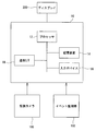
- FIG. 1 is a block diagram showing a physical configuration of the video processing device 10
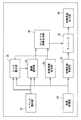
- FIG. 2 is a block diagram showing a functional configuration of the video processing device 10.
- the video processing device 10 extracts a representative image representing the video from a plurality of frame images constituting the video captured by the surveillance camera 100, and generates a thumbnail image.
- a surveillance camera is taken as an example, but the camera is not limited to the surveillance camera as long as it captures a moving image, and other cameras may be used.
- the video processing device 10 is physically a processor 12, a storage device 14 connected to the processor 12 via a bus, a communication interface 18 (hereinafter abbreviated as “communication I / F18”), and an input device. It is a computer having 16. Further, the video processing device 10 may be connected to a display 200 for displaying various images, for example, thumbnail images described later, if necessary.
- the processor 12 executes various operations according to a program, and is, for example, a CPU.
- the storage device 14 stores various programs and data, and is composed of, for example, a semiconductor memory, a hard disk drive, a solid state drive, or a combination thereof.
- the communication I / F 18 is for transmitting and receiving data by wire or wirelessly to and from a device outside the video processing device 10, and is a connector, an antenna, a communication chip, or a communication chip conforming to a predetermined communication standard. It is composed of a combination of these.
- the input device 16 receives an operation instruction from an operator, and is composed of, for example, a keyboard, a mouse, a microphone, a touch panel, or a combination thereof.
- the video processing device 10 may be composed of a plurality of computers.
- the video processing device 10 includes a main computer that executes complicated arithmetic processing and a sub computer (for example, a personal digital assistant) capable of communicating with the main computer, and the user can use the input device of the sub computer.
- a sub computer for example, a personal digital assistant
- various arithmetic processes may be performed on the main computer.
- the video processing device 10 is realized by a computer, but the video processing device 10 may be realized by an embedded device incorporated in another device / device.
- a surveillance camera 100 and an event monitoring unit 102 are connected to the video processing device 10.
- the surveillance camera 100 captures a predetermined target space.
- the target section may be indoors or outdoors.
- the surveillance camera 100 may be a fixed camera whose position and posture do not change, or a movable camera whose position or posture can be changed within a predetermined range.
- the video data obtained by the shooting by the surveillance camera 100 is sequentially sent to the video processing device 10 and stored in the storage device 14 via the communication I / F 18.
- the event monitoring unit 102 monitors the presence or absence of an event, and if an event occurs, notifies the video processing device 10 to that effect. As will be described later, the video processing device 10 extracts one representative image from a plurality of frame images constituting the video during the event period. What is defined as an event can be appropriately changed according to the installation purpose and installation location of the surveillance camera 100. For example, the event may be specified to occur periodically (eg, every 3 minutes for 30 seconds). Further, when the surveillance camera 100 is installed in a process execution space such as a factory, the execution period of a specific process may be set as an event. Further, the timing at which a large change occurs in the image or sound may be set as an event.
- an event is set as an event in which a person gets in or out of the elevator or an animal, an animal, or a moving object (a car, a drone, etc.) enters the elevator hall. You may. Further, the timing at which a sound of a certain level or higher is generated may be specified as the event occurrence timing. Further, as another form, the timing at which a specific instruction input occurs may be specified as the event occurrence timing. For example, when the surveillance camera 100 is installed in the elevator hall of the facility, pressing the elevator button may be specified as an event occurrence timing.
- the event monitoring unit 102 monitors the occurrence state of such an event and sends the result to the video processing device 10.
- the event monitoring unit 102 sends at least an event start signal indicating the start of the event to the video processing device 10. Further, in addition to the event start signal, the event monitoring unit 102 may also send an event end signal indicating the end of the event to the video processing device 10.
- the event monitoring unit 102 may be, for example, a part of a building monitoring facility. Further, the event monitoring unit 102 may be incorporated in the video processing device 10 instead of being a separate device from the video processing device 10.
- the video processing device 10 has a video receiving unit 22 that receives video data acquired by the surveillance camera 100.
- the video receiving unit 22 sends the received video data to the video recording control unit 26, the score calculation unit 32, the image selection unit 34, and the background image extraction unit 36.
- the video recording control unit 26 stores the received video data in the storage 28 after associating it with a time stamp or the like.
- the storage 28 stores video data and thumbnail images taken by the surveillance camera 100, and is physically a storage device 14.
- the video processing device 10 is also provided with an event notification unit 24 that receives a signal related to the event from the event monitoring unit 102.
- the event notification unit 24 determines the start and end timings of the event based on the signals from the event monitoring unit 102, and notifies the score calculation unit 32 and the image selection unit 34 of the event notification signals indicating these timings.
- the event end signal is transmitted from the event monitoring unit 102
- the event end timing is determined based on the event end signal.
- the event notification unit 24 may determine the timing at which a predetermined time has elapsed from the reception of the event start signal as the event end timing.
- the event notification unit 24 and the video reception unit 22 are physically communication I / F18.
- the score calculation unit 32 calculates a representative score for each of the plurality of frame images constituting the video during the event period. Since the procedure for calculating the representative score will be described in detail later, the detailed description here will be omitted. As will be described in detail later, in addition to the frame image and the event start / end signal constituting the video during the event period, the background image extracted by the background image extraction unit 36 may be input to the score calculation unit 32. Good. The score calculation unit 32 sends the calculated representative score together with the ID of the corresponding frame image to the image selection unit 34 sequentially or collectively.
- the image selection unit 34 selects a representative image representing the video of one event period based on the calculated representative score.
- the frame image having the maximum representative score is selected as the representative image during the event period.
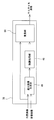
- FIG. 3 is a block diagram showing an example of a specific configuration of the image selection unit 34.
- the image selection unit 34 is provided with an image buffer 42 that temporarily stores a plurality of frame images constituting the video during the event period.
- the image selection unit 34 is also provided with a maximum score detection unit 40.
- the maximum score detection unit 40 identifies the maximum representative score from the plurality of representative scores sent from the score calculation unit 32, and identifies the ID of the frame image corresponding to the maximum representative score. Then, the maximum score detection unit 40 sends the ID of the specified frame image to the image identification unit 44.
- the image specifying unit 44 reads the frame image with the sent ID from the image buffer 42, and identifies this frame image as a representative image in this event.
- the identified representative image is sent to the thumbnail image generation unit 38 as shown in FIG.
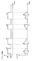
- FIG. 4 is an image diagram showing a specific state of the representative image.
- the upper part shows the event occurrence state
- ON (high) indicates the period during the event
- OFF (low) indicates the period during which the event does not occur.
- the lower row shows the representative score calculated during each event period.
- the maximum score detection unit 40 specifies the frame image having the maximum representative score as the representative image during one event period. Therefore, in the example of FIG. 4, the frame image captured at time t1 is specified as the representative image representing the event E1. Similarly, the frame images captured at time t2, t3, and t4 are identified as representative images representing events E2, E3, and E4, respectively.
- the thumbnail image generation unit 38 generates a thumbnail image of the sent representative image and stores the thumbnail image in the storage 28. At this time, the thumbnail image is stored together with the information indicating the time when the representative image was captured or the start time of the event to which the representative image belongs.
- the thumbnail image may be the representative image itself or an image obtained by reducing the representative image (lowering the resolution).
- the thumbnail image generation unit 38 emphasizes the subject portion of the representative image to generate a thumbnail image.
- FIG. 5 is a diagram showing an example of a specific configuration of the thumbnail image generation unit 38.
- the background image provided by the background image extraction unit 36 is also input to the thumbnail image generation unit 38.
- the background image is an image that constitutes the background of a plurality of frame images that constitute an image.
- the background image may be registered by the operator in advance, or may be automatically extracted by the background image extraction unit 36 based on the video data.
- the background image extraction unit 36 can extract the captured frame image as the background image during the period when the event does not occur or during the period when the subject such as a person, an animal, or a moving object is not reflected. ..
- the thumbnail image generation unit 38 includes a difference image generation unit 46 that extracts only the differences between the representative image and the background image. Therefore, the difference image is usually an image of a subject portion such as a person, an animal, or a moving body.
- the generated difference image is sent to the enhancement processing unit 48.
- the enhancement processing unit 48 performs enhancement processing on the difference image which is an image of the subject portion.
- the enhancement process is not particularly limited as long as the subject included in the difference image is more conspicuous than the background. Therefore, the enhancement processing unit 48 may, for example, process edge enhancement, color tone change, brightness increase, contrast enhancement, border addition, or a combination thereof of the difference image.
- the enhanced difference image is sent to the superimposing unit 50 together with the representative image.
- the superimposition unit 50 synthesizes the emphasized difference image with the representative image, and generates a thumbnail image based on the composite image.
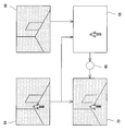
- FIG. 6 is an image diagram showing a state of thumbnail image generation.
- the representative image 64 and the background image 66 are input to the thumbnail image generation unit 38.
- the representative image 64 is different from the background image 66 in that a subject such as a person is reflected in the representative image 64.
- the thumbnail image generation unit 38 extracts a portion of the representative image 64 that is different from the background image 66 as a difference image 68.
- a portion showing a person is extracted as a difference image 68.
- the thumbnail image generation unit 38 enhances the extracted difference image 68 and then synthesizes it with the representative image 64. Then, a thumbnail image is generated based on the obtained composite image 70.
- the thumbnail images displayed on the display 200 are rarely single, and usually, a plurality of thumbnail images are often displayed in a list. Further, in order to enable the display of a plurality of thumbnail images, the size of each thumbnail image is often small. In this case, it may be difficult to clearly grasp the characteristics of the subject captured in one thumbnail image. However, as described above, by emphasizing the subject portion, the characteristics of the subject can be clearly grasped as compared with the case where the subject portion is not emphasized.
- the emphasized difference image and the representative image are combined, but the background image may be combined with the difference image instead of the representative image.
- deterioration processing edge blunting, brightness reduction, color tone change, blurring processing, etc.
- the characteristics of the event can be grasped more clearly from the thumbnail image.
- the frame image having the maximum representative score is selected as the representative image during one event period. Therefore, the characteristics of the frame image selected as the representative image change depending on the calculation method of the representative score.
- the amount of blurring of each of the plurality of frame images constituting the video during the event period is calculated, and the representative score is calculated based on at least the amount of blurring.
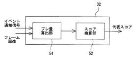
- FIG. 7 is a diagram showing an example of the configuration of the score calculation unit 32.
- the score calculation unit 32 includes a blur amount calculation unit 54 that calculates the blur amount of the frame image, and a score conversion unit 52 that converts the calculated blur amount into a representative score.
- the blur amount calculation unit 54 calculates the blur amount of the image included in one frame image from the one frame image. In other words, the blur amount calculation unit 54 calculates the blur amount of one frame image without referring to another frame image. More specifically, the blur amount calculation unit 54 calculates the blur amount based on the autocorrelation between the frame image and the comparative image in which the frame image is moved in a predetermined movement direction by a predetermined movement distance.
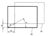
- FIG. 8 is an image diagram showing a state of calculating the amount of blur.
- the blur amount calculation unit 54 assumes a comparison image 62 in which the frame image 60 is moved in the direction of the movement angle ⁇ by the movement distance dr, and the comparison image 62 and the frame image 60 are self-combined.
- the correlation S is calculated.
- the autocorrelation S can be calculated by the following equation 1.
- R (i, j) indicates R at the coordinates (i, j) of the frame image, that is, the color value of red.
- G (i, j) and B (i, j) indicate G and B, that is, green and blue color values at the coordinates (i, j) of the frame image.
- the number of pixels of the frame image is W ⁇ H, and the values of W ⁇ H are integrated.
- the blur amount calculation unit 54 calculates a plurality of autocorrelation S while changing the combination of the movement angle ⁇ and the movement distance dr. Therefore, when the movement angle ⁇ is changed N1 times and the movement distance dr is changed N2 times, the autocorrelation S is calculated by N1 ⁇ N2.
- the change interval and upper limit of the movement angle ⁇ and the movement distance dr are not particularly limited, but for example, the movement angle ⁇ may be changed from 0 ° to 360 ° at 10 ° intervals. Further, the moving distance dr may be changed, for example, from 0 to 10 at 1 interval.
- the blur amount calculation unit 54 identifies the maximum autocorrelation S among the plurality of autocorrelation S. Then, the moving distance dr when the maximum autocorrelation S is calculated is output as the amount of blurring of the frame image 60.
- the calculated blur amount of each frame image is input to the score conversion unit 52.
- the score conversion unit 52 converts the amount of blurring of each frame image into a representative score of the frame image.
- This conversion method is not particularly limited as long as the representative score depends on the amount of blurring.
- the value obtained by reversing the amount of blur is calculated as a representative score.
- the representative score C Bmax-B may be set.
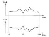
- FIG. 9 is an image diagram showing how the representative score is calculated.
- the upper part of FIG. 9 is a graph showing the amount of blurring of the frame image obtained during a specific event period, and the lower part is a graph showing the representative score of the frame image.
- the event continues from time t0 to time tmax.
- the amount of blur changes with the passage of time, but takes the minimum value at time t1. Since the representative score is a value obtained by flipping this amount of blur upside down, the representative score takes the maximum value at the same time t1.
- the score conversion unit 52 sends the representative score acquired in this way to the image selection unit 34 together with the ID of the corresponding frame image.
- the score conversion unit 52 may send the representative score and ID to the image selection unit 34 each time a representative score of one frame image is obtained.
- the score conversion unit 52 may collectively send the representative scores and IDs of all the plurality of frame images constituting the video during one event period to the image selection unit 34.
- the image selection unit 34 selects the frame image having the maximum representative score as the representative image. Therefore, in the example of FIG. 9, the frame image taken at time t1 is selected as the representative image.
- the representative score is calculated based on the amount of blurring of the frame image, and the smaller the amount of blurring, the easier it is to select the representative image.
- the amount of blur is calculated based on the moving distance dr when the autocorrelation S takes the maximum value, but the method of calculating the amount of blur may be changed as appropriate.
- the frame image may be Fourier transformed to obtain a spectrum, and the amount of blur may be calculated based on the intensity ratio of the low frequency component and the high frequency component.
- the value obtained by reversing the amount of blur is used as the representative score, but the amount of blur itself may be used as the representative score.
- the image selection unit 34 may select the frame image having the minimum representative score as the representative image.
- the representative image does not necessarily have to be the frame image having the maximum or minimum representative score as long as the frame image having less blurring is selected based on the value of the representative score.
- the frame image having the second highest representative score may be selected as the representative image.
- FIG. 10 is a diagram showing another example of the configuration of the score calculation unit 32.
- the score calculation unit 32 includes a blur amount calculation unit 54, a motion vector calculation unit 56 that calculates a motion vector between two frame images, and a score conversion that converts the calculated blur amount and motion vector into a representative score.
- a unit 52 and the like are provided.
- the configuration of the blur amount calculation unit 54 is the same as the configuration of the blur amount calculation unit 54 in FIG. 7.
- the motion vector calculation unit 56 determines the motion vector of the target frame image based on the current frame image (target frame image) and the frame image (reference frame image) of a predetermined time (for example, one frame before) the target frame image. Is calculated. Specifically, the motion vector calculation unit 56 divides the target frame image into N (N ⁇ 2) sub-blocks, shifts each sub-block in the reference frame image, and searches for the best matching part. To do. The motion vector calculation unit 56 obtains the shift amount for all the sub-blocks, and calculates the sum of squares as the motion vector of the target frame image. That is, when the shift amount in the x direction of the i-th subblock is Mx (i) and the shift amount in the y direction is My (i), the motion vector M of the target frame image can be obtained by Equation 2.
- the motion vector calculated by the motion vector calculation unit 56 is sent to the score conversion unit 52 together with the ID of the frame image.
- the score conversion unit 52 calculates the representative score of each of the plurality of frame images based on the blur amount calculated by the blur amount calculation unit 54 and the motion vector calculated by the motion vector calculation unit 56.
- the attention period is set based on the timing when the motion vector takes the maximum value during one event period, and the representative scores of a plurality of frame images constituting the video of the attention period are calculated based on the amount of blur.
- the representative score of the other frame images is set to 0.
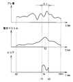
- FIG. 11 is an image diagram showing how the representative score is calculated. In FIG. 11, the upper row shows the amount of blurring during one event period, the middle row shows the motion vector, and the lower row shows the representative score.
- the motion vector takes the maximum value at time t2. Therefore, it can be inferred that the movement of the subject in the image is particularly large around this time t2.
- a fixed period before and after the time t2 at which this motion vector is maximized is set as the attention period ⁇ t.
- the period from the time t1 which is the past by the predetermined time ⁇ from the time t2 to the time t3 which is the future by the predetermined time ⁇ from the time t2 is the attention period ⁇ t. Then, for the frame image constituting the image of the attention period ⁇ t, the representative score is calculated based on the amount of blurring.
- the value obtained by subtracting the amount of blur from the upper limit of the amount of blur is calculated as the representative score.
- the representative score of the frame image constituting the video in the period other than the attention period ⁇ t that is, the time t0 to t1 and the time t3 to tmax is 0.
- the representative score becomes the maximum at the time ta within the attention period ⁇ t. Therefore, in this case, the frame image at time ta is selected as the representative image.
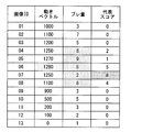
- FIG. 12 is a diagram showing an example of a table recorded by the score conversion unit 52 for calculating the representative score.
- the score conversion unit 52 temporarily stores the motion vector and the amount of blur sequentially sent from the motion vector calculation unit 56 and the blur amount calculation unit 54 together with the ID of the frame image in the form of the table shown in FIG. If the motion vector and the amount of blur can be calculated for all the frame images constituting one event period, the score conversion unit 52 sets the attention period with reference to this table.
- the frame image of the image ID 06 and the two frame images before and after the frame image are specified as the frame images of the attention period.
- the score conversion unit 52 calculates a value obtained by subtracting the amount of blurring of these five frame images from the upper limit value (10 in the illustrated example) as a representative score.
- the representative scores of the other frame images are all set to 0.
- the score conversion unit 52 also records the calculated representative score in a table, and then sends the table to the image selection unit 34.
- the image selection unit 34 selects a representative image based on the representative score recorded in the table. In the example of FIG. 12, the image ID 07 having the maximum representative score is selected as the representative image.
- the representative image is an image that makes it easy to grasp the events that occurred during each event period.
- the event causes some movement, it is easier to grasp the content of the event in the image when the movement is large than in the image when the movement is small.
- the image when the two people move their hands and try to grab the other person is better than the image where the two people are just standing. It is easier to understand the situation.
- the period for calculating the representative score is limited to a certain period (attention period) before and after the timing when the motion vector reaches the maximum value.
- the representative score of the frame image during the attention period is calculated based on the blur amount so that the image having a small blur amount is selected as the representative image during the attention period.
- the attention period may be set by another procedure as long as it is set based on the motion vector.
- the attention period may be a fixed period after the maximum motion vector timing, and the past from the maximum motion vector timing may not be included in the attention period.
- the moving average of the motion vector may be calculated, and the period in which the moving average value becomes the highest may be set as the attention period.
- the representative score is calculated based on both the motion vector and the amount of blur, it is not necessary to set the attention period.
- a function with the motion vector M and the amount of blur B as variables may be set, and the representative score C may be calculated based on the functions.
- C K1, M + K2, B may be set (K1 and K2 are coefficients).
- FIG. 13 is a diagram showing another example of the configuration of the score calculation unit 32.
- the score calculation unit 32 includes a blur amount calculation unit 54, a background subtraction calculation unit 58 that calculates the difference between the frame image and the background image, and score conversion that converts the calculated blur amount and background difference into a representative score.
- a unit 52 and a unit 52 are provided.
- the configuration of the blur amount calculation unit 54 is the same as the configuration of the blur amount calculation unit 54 in FIG. 7.
- the background subtraction calculation unit 58 calculates the amount of difference between the target frame image and the background image as background subtraction.
- the background image is an image provided by the background image extraction unit 36, and is an image constituting the background of a plurality of frame images constituting the image.
- the calculation method of background subtraction is not limited as long as it is a parameter representing the difference between the frame image and the background image. In this example, the sum of squares of the difference in pixel values between the target frame image and the background image is calculated as background subtraction. Therefore, the background subtraction D is represented by Equation 3.
- Rt (i, j) indicates the R value at the coordinates i, j of the target frame image
- Rb (i, j) indicates the R value at the coordinates i, j of the background image.
- Gt (i, j) and Bt (i, j) are the G and B values at the coordinates i and j of the target frame image
- Gb (i, j) and Bb (i, j) are the G and B values.
- G value and B value at coordinates i and j of the background image are shown, respectively.
- the background subtraction calculated by the background subtraction calculation unit 58 is sent to the score conversion unit 52 together with the ID of the frame image.
- the score conversion unit 52 calculates the representative score of each of the plurality of frame images based on the blur amount calculated by the blur amount calculation unit 54 and the background subtraction calculated by the background subtraction calculation unit 58.
- the background subtraction calculation method described here is an example, and if the degree of difference between the frame image and the background image can be expressed, the value calculated by another method is used as the "background subtraction". You may handle it. For example, the number of pixels in which the difference in pixel values between the frame image and the background image is equal to or greater than a predetermined threshold value may be used as the background difference.
- attention period is set based on the timing when background subtraction takes the maximum value during one event period, and representative scores of a plurality of frame images constituting the video of the attention period are calculated based on the amount of blurring.
- the representative scores of the other frame images are set to 0.
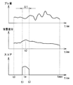
- FIG. 14 is an image diagram showing how the representative score is calculated.
- the upper row shows the amount of blurring during one event period
- the middle row shows the background subtraction
- the lower row shows the representative score.
- the background subtraction takes the maximum value at time t2.
- the background subtraction tends to increase as the number of subjects (for example, people) shown in the frame image increases.
- the background subtraction is greater when multiple subjects are dispersed without partially overlapping (and by extension, the total area of all subjects is large). , Easy to grow. Therefore, in the vicinity of time t2 where the background subtraction is maximum, it is highly possible that most of the subjects involved in the event are captured with little overlap.
- a certain period before and after the time t2 at which this background subtraction is maximized is set as the attention period ⁇ t.
- the period from the time t1 which is the past by the predetermined time ⁇ from the time t2 to the time t3 which is the future by the predetermined time ⁇ from the time t2 is the attention period ⁇ t.
- the representative score is calculated based on the amount of blurring. Specifically, the value obtained by subtracting the amount of blur from the maximum value of the amount of blur is calculated as the representative score.
- the representative score of the frame image constituting the video in the period other than the attention period ⁇ t that is, the time t0 to t1 and the time t3 to tmax is 0.
- the representative score becomes the maximum at the time ta within the attention period ⁇ t.
- the score conversion unit 52 records the blur amount, background subtraction, and representative score calculated in this way in the same table as in FIG. 12, and then sends the table to the image selection unit 34.
- the image selection unit 34 refers to the sent table and selects the frame image having the maximum representative score as the representative image. In the example of FIG. 14, the frame image at time ta is selected as the representative image.
- the representative image is an image that makes it easy to grasp the events that occurred during each event period.
- the period for calculating the representative score is limited to a certain period (attention period) before and after the timing when the background subtraction reaches the maximum value.
- a frame image in which more subjects are captured with less overlap is likely to remain as a candidate for a representative image.
- the representative score of the frame image during the attention period is calculated based on the blur amount so that the image having a small blur amount is selected as the representative image during the attention period.
- the attention period may be set by another procedure as long as it is set based on the background subtraction.
- the attention period may be a fixed period after the background subtraction maximum timing, and the past from the background subtraction maximum timing may not be included in the attention period.
- the moving average of background subtraction may be calculated, and the period in which the moving average value becomes the highest may be set as the period of interest.
- the representative score is calculated based on both the background subtraction and the amount of blurring, it is not necessary to set the attention period.
- a function with background subtraction D and blur amount B as variables may be set, and a representative score C may be calculated based on the functions.
- C K1, D + K2, B may be set (K1 and K2 are coefficients).
- FIG. 15 is a diagram showing another example of the configuration of the score calculation unit 32.
- the score calculation unit 32 includes a blur amount calculation unit 54, a motion vector calculation unit 56, a background subtraction calculation unit 58, and a score conversion unit 52.
- the configurations of the blur amount calculation unit 54, the motion vector calculation unit 56, and the background subtraction calculation unit 58 are the same as the configurations of the respective calculation units described so far.
- the score conversion unit 52 calculates the representative score of each of the plurality of frame images constituting the video during the event period based on the blur amount, the motion vector, and the background subtraction calculated by each calculation unit. Specifically, the score conversion unit 52 sets the first attention period based on the background subtraction during the event period, and further sets the second attention period based on the motion vector during the first attention period. The representative scores of a plurality of frame images constituting the video of the second attention period are calculated based on the amount of blurring.
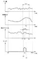
- FIG. 16 is an image diagram showing how the representative score is calculated.
- the four graphs shown in FIG. 16 show the amount of blurring, background subtraction, motion vector, and representative score during one event period, in order from the top.
- the background subtraction takes the maximum value at time ta.
- a fixed period before and after the time ta at which this background subtraction is maximized is set as the first attention period ⁇ t1.
- the period from the time t1 which is the past by the predetermined time ⁇ from the time ta to the time t4 which is the future by the predetermined time ⁇ from the time ta is the first attention period ⁇ t1.
- the motion vector takes the maximum value at time tb.
- the score conversion unit 52 sets a fixed period before and after this time tb as the second attention period ⁇ t2.
- the period from the time t2, which is the past by the predetermined time ⁇ from the time tb, to the time t3, which is the future by the predetermined time ⁇ from the time tb, is the second attention period ⁇ t2. If the second attention period ⁇ t2 can be specified, the score conversion unit 52 calculates the representative score of the frame image constituting the video of the second attention period ⁇ t2 based on the blur amount.
- the value obtained by subtracting the amount of blur from the upper limit of the amount of blur is calculated as the representative score.
- the representative score of the frame image constituting the video in the period other than the second attention period ⁇ t2, that is, the time t0 to t2 and the time t3 to tmax is 0.
- the score conversion unit 52 temporarily stores the blur amount, background subtraction, and motion vector calculated by each calculation unit in the table together with the ID of the corresponding frame image. Then, if these values can be obtained for all the frame images constituting the video of one event period, the representative score of each frame image is calculated by referring to the table.
- the calculated representative score is sent to the image selection unit 34.
- the image selection unit 34 selects the frame image having the maximum representative score as the representative image. Therefore, in the example of FIG. 16, the frame image at the time tc within the second attention period ⁇ t2 is selected as the representative image.
- the procedure for setting the first attention period and the second attention period may be changed as appropriate.
- the attention period instead of setting the attention period based on the maximum values of background subtraction and motion vector, the attention period may be set based on the maximum value of these moving averages.
- the representative score is calculated based on background subtraction, motion vector, and amount of blur, it is not necessary to set the attention period.
- a function with background subtraction D, motion vector M, and blur amount B as variables may be set, and a representative score C may be calculated based on the functions.
- C K1, D + K2, M + K3, B may be used (K1, K2, K3 are coefficients).
Landscapes
- Engineering & Computer Science (AREA)
- Multimedia (AREA)
- Signal Processing (AREA)
- Image Analysis (AREA)
- Television Signal Processing For Recording (AREA)
- Closed-Circuit Television Systems (AREA)
Priority Applications (3)
| Application Number | Priority Date | Filing Date | Title |
|---|---|---|---|
| JP2021519988A JP7317954B2 (ja) | 2019-05-22 | 2019-05-22 | 映像処理装置および映像処理方法 |
| PCT/JP2019/020312 WO2020235060A1 (ja) | 2019-05-22 | 2019-05-22 | 映像処理装置および映像処理方法 |
| CN201980096562.1A CN113841389B (zh) | 2019-05-22 | 2019-05-22 | 影像处理装置及影像处理方法 |
Applications Claiming Priority (1)
| Application Number | Priority Date | Filing Date | Title |
|---|---|---|---|
| PCT/JP2019/020312 WO2020235060A1 (ja) | 2019-05-22 | 2019-05-22 | 映像処理装置および映像処理方法 |
Publications (1)
| Publication Number | Publication Date |
|---|---|
| WO2020235060A1 true WO2020235060A1 (ja) | 2020-11-26 |
Family
ID=73459349
Family Applications (1)
| Application Number | Title | Priority Date | Filing Date |
|---|---|---|---|
| PCT/JP2019/020312 Ceased WO2020235060A1 (ja) | 2019-05-22 | 2019-05-22 | 映像処理装置および映像処理方法 |
Country Status (3)
| Country | Link |
|---|---|
| JP (1) | JP7317954B2 (cg-RX-API-DMAC7.html) |
| CN (1) | CN113841389B (cg-RX-API-DMAC7.html) |
| WO (1) | WO2020235060A1 (cg-RX-API-DMAC7.html) |
Cited By (2)
| Publication number | Priority date | Publication date | Assignee | Title |
|---|---|---|---|---|
| CN114827394A (zh) * | 2021-01-20 | 2022-07-29 | 佳能株式会社 | 运动矢量计算装置、摄像装置和运动矢量计算方法 |
| US20230260139A1 (en) * | 2020-08-04 | 2023-08-17 | Mitsubishi Electric Corporation | Moving body tracking system, moving body tracking device, non-transitory computer-readable medium, and moving body tracking method |
Citations (7)
| Publication number | Priority date | Publication date | Assignee | Title |
|---|---|---|---|---|
| JP2005210573A (ja) * | 2004-01-26 | 2005-08-04 | Mitsubishi Electric Corp | 映像表示システム |
| JP2007189558A (ja) * | 2006-01-13 | 2007-07-26 | Toshiba Corp | 映像表示システム及び映像蓄積配信装置 |
| JP2007300443A (ja) * | 2006-04-30 | 2007-11-15 | Victor Co Of Japan Ltd | サムネイル作成装置 |
| JP2010177894A (ja) * | 2009-01-28 | 2010-08-12 | Sony Corp | 撮像装置、画像管理装置及び画像管理方法、並びにコンピューター・プログラム |
| JP2013118574A (ja) * | 2011-12-05 | 2013-06-13 | Nikon Corp | 撮像装置 |
| JP2016119552A (ja) * | 2014-12-19 | 2016-06-30 | 三星電子株式会社Samsung Electronics Co.,Ltd. | 映像コンテンツ処理装置、映像コンテンツ処理方法及びプログラム |
| JP2018007156A (ja) * | 2016-07-06 | 2018-01-11 | オリンパスメモリーワークス株式会社 | 画像検索装置、画像検索方法及びプログラム |
Family Cites Families (11)
| Publication number | Priority date | Publication date | Assignee | Title |
|---|---|---|---|---|
| JP4369308B2 (ja) * | 2004-06-10 | 2009-11-18 | 日本電信電話株式会社 | 代表画像選択装置,代表画像選択方法および代表画像選択プログラム |
| JP4418400B2 (ja) * | 2005-05-20 | 2010-02-17 | オリンパスメディカルシステムズ株式会社 | 画像表示装置 |
| US7990475B1 (en) * | 2006-09-05 | 2011-08-02 | Adobe Systems Incorporated | Methods and apparatus for automated representative image selection |
| JP4909315B2 (ja) * | 2008-06-05 | 2012-04-04 | 日本電信電話株式会社 | 映像処理装置及び方法及びプログラム及びコンピュータ読取可能な記録媒体 |
| JP2012029175A (ja) * | 2010-07-26 | 2012-02-09 | Canon Inc | 画像解析装置及び画像解析方法 |
| JP2012169701A (ja) * | 2011-02-09 | 2012-09-06 | Canon Inc | 画像処理装置、画像処理方法及びプログラム |
| JP5952625B2 (ja) * | 2011-06-23 | 2016-07-13 | キヤノン株式会社 | 情報処理装置、情報処理方法、及びプログラム |
| US20140333669A1 (en) * | 2013-05-08 | 2014-11-13 | Nvidia Corporation | System, method, and computer program product for implementing smooth user interface animation using motion blur |
| CN103514580B (zh) * | 2013-09-26 | 2016-06-08 | 香港应用科技研究院有限公司 | 用于获得视觉体验优化的超分辨率图像的方法和系统 |
| JP2017204753A (ja) * | 2016-05-11 | 2017-11-16 | 富士通株式会社 | フレーム抽出方法、動画再生制御方法、プログラム、フレーム抽出装置及び動画再生制御装置 |
| US10812770B2 (en) * | 2017-09-13 | 2020-10-20 | Canon Kabushiki Kaisha | Image processing system, image processing apparatus, image processing method, and program |
-
2019
- 2019-05-22 WO PCT/JP2019/020312 patent/WO2020235060A1/ja not_active Ceased
- 2019-05-22 JP JP2021519988A patent/JP7317954B2/ja active Active
- 2019-05-22 CN CN201980096562.1A patent/CN113841389B/zh active Active
Patent Citations (7)
| Publication number | Priority date | Publication date | Assignee | Title |
|---|---|---|---|---|
| JP2005210573A (ja) * | 2004-01-26 | 2005-08-04 | Mitsubishi Electric Corp | 映像表示システム |
| JP2007189558A (ja) * | 2006-01-13 | 2007-07-26 | Toshiba Corp | 映像表示システム及び映像蓄積配信装置 |
| JP2007300443A (ja) * | 2006-04-30 | 2007-11-15 | Victor Co Of Japan Ltd | サムネイル作成装置 |
| JP2010177894A (ja) * | 2009-01-28 | 2010-08-12 | Sony Corp | 撮像装置、画像管理装置及び画像管理方法、並びにコンピューター・プログラム |
| JP2013118574A (ja) * | 2011-12-05 | 2013-06-13 | Nikon Corp | 撮像装置 |
| JP2016119552A (ja) * | 2014-12-19 | 2016-06-30 | 三星電子株式会社Samsung Electronics Co.,Ltd. | 映像コンテンツ処理装置、映像コンテンツ処理方法及びプログラム |
| JP2018007156A (ja) * | 2016-07-06 | 2018-01-11 | オリンパスメモリーワークス株式会社 | 画像検索装置、画像検索方法及びプログラム |
Cited By (3)
| Publication number | Priority date | Publication date | Assignee | Title |
|---|---|---|---|---|
| US20230260139A1 (en) * | 2020-08-04 | 2023-08-17 | Mitsubishi Electric Corporation | Moving body tracking system, moving body tracking device, non-transitory computer-readable medium, and moving body tracking method |
| US12482115B2 (en) * | 2020-08-04 | 2025-11-25 | Mitsubishi Electric Corporation | Moving body tracking system, moving body tracking device, non-transitory computer-readable medium, and moving body tracking method |
| CN114827394A (zh) * | 2021-01-20 | 2022-07-29 | 佳能株式会社 | 运动矢量计算装置、摄像装置和运动矢量计算方法 |
Also Published As
| Publication number | Publication date |
|---|---|
| CN113841389A (zh) | 2021-12-24 |
| JPWO2020235060A1 (cg-RX-API-DMAC7.html) | 2020-11-26 |
| CN113841389B (zh) | 2023-11-10 |
| JP7317954B2 (ja) | 2023-07-31 |
Similar Documents
| Publication | Publication Date | Title |
|---|---|---|
| US11977981B2 (en) | Device for automatically capturing photo or video about specific moment, and operation method thereof | |
| JP6049448B2 (ja) | 被写体領域追跡装置、その制御方法及びプログラム | |
| US20180225852A1 (en) | Apparatus and method for generating best-view image centered on object of interest in multiple camera images | |
| WO2019072243A1 (zh) | 动作识别、姿势估计的方法及装置 | |
| JP6362085B2 (ja) | 画像認識システム、画像認識方法およびプログラム | |
| WO2016006027A1 (ja) | 脈波検出方法、脈波検出プログラム及び脈波検出装置 | |
| JP2009531927A5 (cg-RX-API-DMAC7.html) | ||
| JP2015088095A (ja) | 情報処理装置および情報処理方法 | |
| CN111819837A (zh) | 静态视频识别 | |
| JP2021105850A (ja) | 画像処理装置及び方法、及び撮像装置 | |
| JPWO2016158001A1 (ja) | 情報処理装置、情報処理方法、プログラム及び記録媒体 | |
| JP2012212373A (ja) | 画像処理装置、画像処理方法及びプログラム | |
| JPWO2018180578A1 (ja) | 画像処理装置、撮像装置、画像処理方法、およびプログラム | |
| JP2012243206A (ja) | 画像処理方法、画像処理装置および画像処理プログラム | |
| JP7317954B2 (ja) | 映像処理装置および映像処理方法 | |
| US10849515B2 (en) | Image processing apparatus and pulse estimation system provided therewith, and image processing method | |
| JP4682820B2 (ja) | オブジェクト追跡装置及びオブジェクト追跡方法、並びにプログラム | |
| JP6544970B2 (ja) | 画像処理装置、画像処理方法、及びプログラム | |
| CN108965806B (zh) | 一种基于远程展销系统的数据传输方法及装置 | |
| US20190158763A1 (en) | Image processing device, image processing method, and program | |
| JP2007052609A (ja) | 手領域検出装置及び手領域検出方法、並びにプログラム | |
| JPWO2021220893A5 (cg-RX-API-DMAC7.html) | ||
| JP2019047336A5 (cg-RX-API-DMAC7.html) | ||
| JP4750758B2 (ja) | 注目領域抽出方法、注目領域抽出装置、コンピュータプログラム、及び、記録媒体 | |
| JP5478533B2 (ja) | 全方位画像生成方法、画像生成装置およびプログラム |
Legal Events
| Date | Code | Title | Description |
|---|---|---|---|
| 121 | Ep: the epo has been informed by wipo that ep was designated in this application |
Ref document number: 19929992 Country of ref document: EP Kind code of ref document: A1 |
|
| ENP | Entry into the national phase |
Ref document number: 2021519988 Country of ref document: JP Kind code of ref document: A |
|
| NENP | Non-entry into the national phase |
Ref country code: DE |
|
| 122 | Ep: pct application non-entry in european phase |
Ref document number: 19929992 Country of ref document: EP Kind code of ref document: A1 |