WO2020230849A1 - 穿刺補助具および穿刺方法 - Google Patents
穿刺補助具および穿刺方法 Download PDFInfo
- Publication number
- WO2020230849A1 WO2020230849A1 PCT/JP2020/019270 JP2020019270W WO2020230849A1 WO 2020230849 A1 WO2020230849 A1 WO 2020230849A1 JP 2020019270 W JP2020019270 W JP 2020019270W WO 2020230849 A1 WO2020230849 A1 WO 2020230849A1
- Authority
- WO
- WIPO (PCT)
- Prior art keywords
- fixing portion
- skin
- puncture
- needle
- region
- Prior art date
- Legal status (The legal status is an assumption and is not a legal conclusion. Google has not performed a legal analysis and makes no representation as to the accuracy of the status listed.)
- Ceased
Links
Images


Classifications
-
- A—HUMAN NECESSITIES
- A61—MEDICAL OR VETERINARY SCIENCE; HYGIENE
- A61M—DEVICES FOR INTRODUCING MEDIA INTO, OR ONTO, THE BODY; DEVICES FOR TRANSDUCING BODY MEDIA OR FOR TAKING MEDIA FROM THE BODY; DEVICES FOR PRODUCING OR ENDING SLEEP OR STUPOR
- A61M5/00—Devices for bringing media into the body in a subcutaneous, intra-vascular or intramuscular way; Accessories therefor, e.g. filling or cleaning devices, arm-rests
- A61M5/42—Devices for bringing media into the body in a subcutaneous, intra-vascular or intramuscular way; Accessories therefor, e.g. filling or cleaning devices, arm-rests having means for desensitising skin, for protruding skin to facilitate piercing, or for locating point where body is to be pierced
- A61M5/425—Protruding skin to facilitate piercing, e.g. vacuum cylinders, vein immobilising means
-
- A—HUMAN NECESSITIES
- A61—MEDICAL OR VETERINARY SCIENCE; HYGIENE
- A61B—DIAGNOSIS; SURGERY; IDENTIFICATION
- A61B5/00—Measuring for diagnostic purposes; Identification of persons
- A61B5/15—Devices for taking samples of blood
- A61B5/150007—Details
- A61B5/150015—Source of blood
- A61B5/15003—Source of blood for venous or arterial blood
-
- A—HUMAN NECESSITIES
- A61—MEDICAL OR VETERINARY SCIENCE; HYGIENE
- A61B—DIAGNOSIS; SURGERY; IDENTIFICATION
- A61B5/00—Measuring for diagnostic purposes; Identification of persons
- A61B5/15—Devices for taking samples of blood
- A61B5/150007—Details
- A61B5/150053—Details for enhanced collection of blood or interstitial fluid at the sample site, e.g. by applying compression, heat, vibration, ultrasound, suction or vacuum to tissue; for reduction of pain or discomfort; Skin piercing elements, e.g. blades, needles, lancets or canulas, with adjustable piercing speed
- A61B5/150106—Means for reducing pain or discomfort applied before puncturing; desensitising the skin at the location where body is to be pierced
- A61B5/15016—Means for reducing pain or discomfort applied before puncturing; desensitising the skin at the location where body is to be pierced by accessories for bringing the piercing element into the body, e.g. through rotation of the piercing element
-
- A—HUMAN NECESSITIES
- A61—MEDICAL OR VETERINARY SCIENCE; HYGIENE
- A61B—DIAGNOSIS; SURGERY; IDENTIFICATION
- A61B5/00—Measuring for diagnostic purposes; Identification of persons
- A61B5/15—Devices for taking samples of blood
- A61B5/150007—Details
- A61B5/150748—Having means for aiding positioning of the piercing device at a location where the body is to be pierced
-
- A—HUMAN NECESSITIES
- A61—MEDICAL OR VETERINARY SCIENCE; HYGIENE
- A61M—DEVICES FOR INTRODUCING MEDIA INTO, OR ONTO, THE BODY; DEVICES FOR TRANSDUCING BODY MEDIA OR FOR TAKING MEDIA FROM THE BODY; DEVICES FOR PRODUCING OR ENDING SLEEP OR STUPOR
- A61M5/00—Devices for bringing media into the body in a subcutaneous, intra-vascular or intramuscular way; Accessories therefor, e.g. filling or cleaning devices, arm-rests
- A61M5/178—Syringes
- A61M5/31—Details
- A61M5/32—Needles; Details of needles pertaining to their connection with syringe or hub; Accessories for bringing the needle into, or holding the needle on, the body; Devices for protection of needles
- A61M5/3287—Accessories for bringing the needle into the body; Automatic needle insertion
-
- A—HUMAN NECESSITIES
- A61—MEDICAL OR VETERINARY SCIENCE; HYGIENE
- A61M—DEVICES FOR INTRODUCING MEDIA INTO, OR ONTO, THE BODY; DEVICES FOR TRANSDUCING BODY MEDIA OR FOR TAKING MEDIA FROM THE BODY; DEVICES FOR PRODUCING OR ENDING SLEEP OR STUPOR
- A61M5/00—Devices for bringing media into the body in a subcutaneous, intra-vascular or intramuscular way; Accessories therefor, e.g. filling or cleaning devices, arm-rests
- A61M5/42—Devices for bringing media into the body in a subcutaneous, intra-vascular or intramuscular way; Accessories therefor, e.g. filling or cleaning devices, arm-rests having means for desensitising skin, for protruding skin to facilitate piercing, or for locating point where body is to be pierced
- A61M5/422—Desensitising skin
Definitions
- the present invention relates to a puncture aid or the like used to puncture the skin of a living body.
- Patent Document 1 discloses a puncture device including a suction plate, a grip portion, a cavity, a check valve, and an injection needle.
- a puncture device including a suction plate, a grip portion, a cavity, a check valve, and an injection needle.
- the technique disclosed in Patent Document 1 by lifting the grip portion upward, the inside of the cavity is made negative pressure and the suction plate sucks the skin. Then, the injection needle is punctured into the skin by releasing the grip portion.
- One aspect of the present invention is to realize a puncture assisting tool capable of preventing the skin from being dented when the needle is punctured into the skin.
- the puncture aid according to one aspect of the present invention is fixed to a first fixing portion fixed to a first region of the skin and a second fixing region of the skin.
- the first fixing portion is movable relative to the second fixing portion so as to have a second fixing portion and pull the skin between the first fixing portion and the second fixing portion. is there.
- FIG. 2 is a cross-sectional view taken along the line AA shown in FIG. It is a figure for demonstrating an example of the puncture method using the said puncture aid. It is a figure for demonstrating an example of the puncture method using the said puncture aid. It is a figure for demonstrating an example of the puncture method using the said puncture aid. It is a figure for demonstrating an example of the puncture method using the said puncture aid. It is a figure for demonstrating an example of the puncture method using the said puncture aid. It is a figure for demonstrating an example of the puncture method using the said puncture aid. It is a perspective view of the puncture aid which concerns on Embodiment 2 of this invention. It is a side view of the said puncture aid.
- FIG. 12 is a cross-sectional view taken along the line BB shown in FIG. (A) to (c) are diagrams for explaining an example of a puncture method using the puncture aid. It is a top view of the puncture assisting tool which concerns on Embodiment 5 of this invention.
- FIG. 15 is a cross-sectional view taken along the line CC shown in FIG.
- FIG. 1 A) to (c) are diagrams for explaining an example of a puncture method using the puncture aid. It is a perspective view of the puncture assisting tool which concerns on Embodiment 6 of this invention. It is a perspective view of the puncture aid which concerns on Embodiment 7 of this invention. It is a figure which looked at the said puncture aid from above in FIG. It is a figure which shows the state when the inside of the frame body of the sticking part is decompressed in the puncture using the puncture aid, and is the cross-sectional view taken along the line DD in FIG.
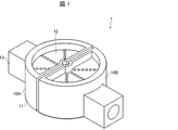
- FIG. 1 is a perspective view of the puncture aid 1.
- FIG. 2 is a view of the puncture assisting tool 1 as viewed from above in FIG.
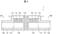
- FIG. 3 is a cross-sectional view taken along the line AA shown in FIG.
- the puncture assisting tool 1 includes a first fixing portion 10A, a second fixing portion 10B, a pump 20A, and a pump 20B.
- the pump 20A (suction device) and the pump 20B (suction device) are not shown in FIGS. 1 and 3.
- the first fixing portion 10A includes a frame body 11, a support body 12, and an exhaust portion 13.
- the frame body 11 has a semi-cylindrical shape obtained by cutting a cylinder on a plane including the central axis.
- the frame body 11 includes one end of the semi-cylinder, a first end 11a which is an end on the side of the living body in contact with the skin, and a second end 11b which is the other end of the semi-cylinder. ing.
- the first end portion 11a has a semicircular shape having an opening inside, while the second end portion 11b is a semicircular flat plate.
- the frame body 11 has a shape in which the surface of the living body in contact with the skin is open.
- the frame 11 has an opening 11c formed in a region of a side surface formed of a semi-cylindrical curved surface in which an exhaust portion 13 described later is installed. Further, a groove 11d recessed inward is formed on the side surface of the frame 11 formed of a semi-cylindrical plane.
- the support 12 is formed inside the frame 11 between the first end 11a and the second end 11b in the axial direction (vertical direction in FIG. 3) of the semi-cylindrical shape of the frame 11.
- the support 12 is made of a semicircular flat plate having a radius having the same length as the inner diameter of the frame 11.
- the support 12 is formed with a plurality of intake holes 12a penetrating the semi-cylindrical shape of the frame 11 in the axial direction.
- the number of intake holes 12a formed in the support 12 is different in FIGS. 1 to 3, the number (density) of the intake holes 12a formed in the support 12 is not particularly limited. It can be appropriately set as long as the strength of the support 12 is not significantly reduced.
- the exhaust unit 13 connects the space inside the frame 11 to the pump 20A.
- the exhaust portion 13 is provided on the side surface of the frame body 11.
- the exhaust portion 13 is formed with a cylindrical hole 13a.
- One end of the hole 13a is connected to the opening 11c provided in the frame 11.
- the pump 20A is connected to the other end of the hole 13a, as shown in FIG.
- the pump 20A is connected to the exhaust portion 13 of the frame body 11 of the first fixing portion 10A.
- the pump 20A decompresses the inside of the frame 11 of the first fixing portion 10A by sucking the air inside the frame 11 of the first fixing portion 10A through the exhaust portion 13.
- the pump 20B is connected to the exhaust portion 13 of the frame body 11 of the second fixed portion 10B.
- the pump 20A depressurizes the inside of the frame 11 of the second fixing portion 10B by sucking the air inside the frame 11 of the second fixing portion 10B through the exhaust portion 13.
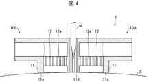
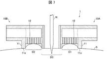
- FIGS. 4 to 7 are diagrams for explaining an example of a puncture method using the puncture assisting tool 1.
- the puncturing assisting tool 1 (more specifically, the first end portion 11a and the second fixing of the frame body 11 of the first fixing portion 10A)
- the first end portion 11a) of the frame body 11 of the portion 10B is brought into contact with the skin S of the living body.
- the needle N installed at the tip of the syringe (not shown) has a groove 11d formed in the frame 11 of the first fixing portion 10A and a groove 11d formed in the frame 11 of the second fixing portion 10B.
- the needle N is not punctured by the skin S of the living body.
- the first fixing portion 10A and the second fixing portion 10B are in contact with each other.
- the inside of the frame 11 of the first fixing portion 10A and the inside of the frame 11 of the second fixing portion 10B are depressurized. Since a plurality of intake holes 12a are formed in the support 12, the entire inside of the frame 11 can be depressurized.
- the first fixing portion 10A and the second fixing portion 10B are moved in the direction away from each other (the direction of the arrow shown in FIG. 5).
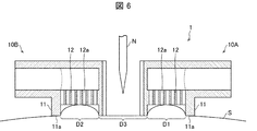
- a region (region D3 shown in FIG. 6) between the regions D1 and D2 in the skin S of the living body is pulled, and tension is applied to the region D3 of the skin S. It becomes.
- the movement of the first fixing portion 10A and the second fixing portion 10B may be performed manually by the operator or may be performed by using a machine using an actuator or the like.
- the actuator for example, an electromagnetic type, a piezoelectric type, a pneumatic type or the like can be used.
- the needle N is punctured into the skin S of the living body by moving the syringe toward the skin S.
- the needle N has a groove 11d formed in the frame 11 of the first fixing portion 10A and a second fixing portion 10B before the first fixing portion 10A and the second fixing portion 10B move. It was located between the groove 11d formed in the frame body 11. Therefore, the portion where the needle N punctures the skin S is the region D3.
- the skin is dented by the pressure of the needle.
- the pain nerves of the living body are stimulated, which causes pain to the living body.
- tension is applied to the region D3 in which the needle N is punctured. Therefore, it is possible to prevent the skin S from being dented when the needle N is punctured.
- the needle N can be punctured without stimulating the nociceptive nerve of the living body (in other words, without causing pain to the living body).
- the puncture assisting tool 1 in the present embodiment relates to the first fixing portion 10A fixed to the region D1 as the first region of the skin S and the region D2 as the second region of the skin S.
- a second fixing portion 10B to be fixed is provided. Then, the first fixing portion 10A becomes relatively movable with respect to the second fixing portion 10B so as to pull the skin S of the region D3 between the first fixing portion 10A and the second fixing portion 10B. There is.
- the first fixing portion 10A fixed to the region D1 of the skin S is moved relative to the second fixing portion 10B fixed to the region D2 of the skin S, thereby moving the region D3.
- Tension can be applied to the skin. This makes it possible to prevent the skin S from being dented when the needle N is punctured. As a result, the needle N can be punctured without stimulating the nociceptive nerve of the living body.
- the puncture aid 1 includes a support 12 that supports the skin S sucked into the frame 11. Further, as shown in FIG. 3, the support 12 is provided on the skin side (upper side in FIG. 3) of the living body with respect to the exhaust portion 13 in the cylindrical axial direction (vertical direction in FIG. 3) of the frame body 11. ing. According to the above configuration, the skin S sucked into the frame 11 is supported by the support 12, as shown in FIG. As a result, it is possible to prevent the exhaust portion 13 from being covered with the skin S. That is, it is possible to prevent the pump 20A or the pump 20B from interfering with the intake air. Therefore, the skin S can be continuously adsorbed on the puncture aid 1.
- the puncture assisting tool of one aspect of the present invention may be configured not to include the support 12.
- the groove 11d for positioning the needle N in the state where the first fixing portion 10A and the second fixing portion 10B are in contact with each other is formed in the first fixing portion 10A and the second fixing portion 10B. It is formed on each frame 11. As a result, the portion where the needle N punctures the skin S can be set as the tensioned region D3.
- a plurality of columnar supports may be formed inside the frame 11 (on the second end 11b).
- the plurality of columnar supports support the skin S and can be inhaled from between the plurality of columnar supports.
- FIG. 8 is a perspective view of the puncture assisting tool 1A in the present embodiment.
- FIG. 9 is a side view of the puncture aid 1A.
- the puncture assisting tool 1A includes a first fixing portion 31A and a second fixing portion 31B.
- the first fixing portion 31A includes a semi-cylindrical member 32 and a grip portion 33.
- the semi-cylindrical member 32 has a semi-cylindrical shape obtained by cutting a cylinder on a plane including the central axis.
- the semi-cylindrical member 32 is one end of the semi-cylinder, and has a first end 32a which is an end on the side of the living body in contact with the skin and a second end 32b which is the other end of the semi-cylinder. I have.
- the first end portion 32a and the second end portion 32b are formed of a semicircular flat plate.
- An adhesive 34 (for example, mucin) is attached to the first end 32a of the semi-cylindrical member 32.
- the puncture method using the puncture aid 1A first, the first end 32a of the semi-cylindrical member 32 of the first fixing portion 31A and the first end 32a of the semi-cylindrical member 32 of the second fixing portion 31B are attached to the skin of the living body. Contact with S. As a result, the adhesive material 34 attached to the first end portion 32a adheres to the skin S.
- the grip portion 33 provided on the side surface of the frame body 11 is gripped, and the first fixing portion 31A and the second fixing portion 31B are moved in a direction away from each other. As a result, the region between the regions adhered to the adhesive material 34 in the skin S of the living body is pulled, and tension is applied to the region.
- the needle N installed at the tip of the syringe (not shown) is punctured into the tensioned region of the skin S of the living body. Also in this embodiment, tension is applied to the region where the needle N is punctured. Therefore, it is possible to prevent the skin S from being dented when the needle N is punctured. As a result, the needle N can be punctured without stimulating the nociceptive nerve of the living body.
- the skin S is adhered to the puncture aid 1A by using the adhesive 34, but the skin S may be adhered to the puncture aid 1A by another method (for example, an adhesive). Good.
- FIG. 10 is a perspective view of the puncture assisting tool 1B in the present embodiment.
- FIG. 11A is a side view of the puncture assisting tool 1B
- FIG. 11B is an enlarged view of a region surrounded by a frame in FIG. 11A.
- the puncture assisting tool 1B includes a first fixing portion 41A and a second fixing portion 41B.
- the first fixing portion 41A includes a semi-cylindrical member 42 and a grip portion 33.
- the semi-cylindrical member 42 has a semi-cylindrical shape obtained by cutting a cylinder on a plane including the central axis.
- the semi-cylindrical member 42 is one end of the semi-cylinder, and has a first end 42a which is an end on the side of the living body in contact with the skin and a second end 42b which is the other end of the semi-cylinder. I have.
- the first end portion 42a and the second end portion 42b are formed of a semicircular flat plate.
- a plurality of spikes 44 protruding perpendicularly to the first end portion 42a are formed on the first end portion 42a of the semi-cylindrical member 42.
- the spike 44 has a spine shape with a barb formed. More specifically, the spike 44 has a diamond-shaped cross section.
- the puncture method using the puncture aid 1B first, the first end 42a of the semi-cylindrical member 42 of the first fixing portion 41A and the first end 42a of the semi-cylindrical member 42 of the second fixing portion 41B are attached to the skin of the living body. Contact with S. As a result, the spike 44 formed on the first end portion 42a is in a state of being caught on the skin S.
- the spike 44 has a length that allows it to be punctured only in the shallow portion of the skin S (specifically, the stratum corneum and the epidermis). As a result, even if the spike 44 is punctured into the skin S, the living body does not feel any damage.
- the grip portion 33 provided on the side surface of the frame body 11 is gripped, and the first fixing portion 41A and the second fixing portion 41B are moved in a direction away from each other. As a result, the region between the regions punctured by the spike 44 in the skin S of the living body is pulled, and tension is applied to the region.
- the spike 44 has a diamond-shaped cross section.
- the spike 44 in other words, the first fixing portion 41A and the second fixing portion 41B
- the spike 44 can be easily moved from the skin S of the living body. It can be pulled out, and when the first fixing portion 41A and the second fixing portion 41B are moved in a direction away from each other, the spike 44 is prevented from coming out from the skin S of the living body.
- the needle N installed at the tip of the syringe (not shown) is punctured into the tensioned region of the skin S of the living body. Also in this embodiment, tension is applied to the region where the needle N is punctured. Therefore, it is possible to prevent the skin S from being dented when the needle N is punctured. As a result, the needle N can be punctured without stimulating the nociceptive nerve of the living body.
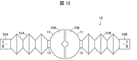
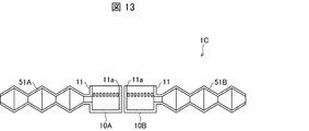
- FIG. 12 is a perspective view of the puncture assisting tool 1C in the present embodiment.
- FIG. 13 is a cross-sectional view taken along the line BB shown in FIG. In the drawings after FIG. 13, for the sake of simplicity, the pumps 52A and 52B, which will be described later, are not shown.
- the puncture assisting tool 1C includes a first fixing portion 10A, a second fixing portion 10B, a ventilation portion 51A, a ventilation portion 51B, a pump 52A, and a pump 52B. There is.
- the ventilation part 51A has a bellows structure that shrinks due to decompression.
- One end of the ventilation portion 51A is connected to the space inside the frame 11 of the first fixing portion 10A via the exhaust portion 13.
- the other end of the vent 51A is connected to the pump 52A.
- the ventilation portion 51B has a bellows structure that shrinks due to decompression.
- One end of the ventilation portion 51B is connected to the space inside the frame 11 of the second fixing portion 10B via the exhaust portion 13.
- the other end of the vent 51B is connected to the pump 52B.
- 14 (a) to 14 (c) are views for explaining an example of a puncture method using the puncture aid 1C.
- the first fixing portion 10A and the second fixing portion 10B are brought into contact with the skin S of the living body.
- the inside of the frame 11 of the first fixing portion 10A and the inside of the frame 11 of the second fixing portion 10B are depressurized.
- the inside of the ventilation portion 51A and the ventilation portion 51B is also depressurized, and the bellows structure of the ventilation portion 51A and the ventilation portion 51B shrinks.
- the first fixing portion 10A and the second fixing portion 10B move in a direction away from each other.
- tension is applied to the region (region D3 shown in FIG. 14C) between the regions D1 and D2 in the skin S of the living body.
- the needle N installed at the tip of the syringe (not shown) is punctured into the tensioned region D3 in the skin S of the living body. Also in this embodiment, tension is applied to the region D3 where the needle N is punctured. Therefore, it is possible to prevent the skin S from being dented when the needle N is punctured. As a result, the needle N can be punctured without stimulating the nociceptive nerve of the living body.
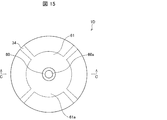
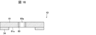
- FIG. 15 is a top view of the puncture assisting tool 1D in the present embodiment.
- FIG. 16 is a cross-sectional view taken along the line CC shown in FIG.
- the puncture aid 1D includes a guide portion 60 and an expansion portion 61.
- the guide portion 60 is provided in the center of the puncture assisting tool 1D, and has a cylindrical shape formed along the axial direction of the cylindrical shape (vertical direction in FIG. 16) through which the needle N passes. It is made up of.
- the guide portion 60 is made of a rigid material.
- the inner diameter of the guide portion 60 (in other words, the diameter of the through hole 60a) is formed so as to be slightly larger than the outer diameter of the needle N.
- the inner diameter of the guide portion 60 may be formed to be 1.05 to 1.2 times the outer diameter of the needle N.
- the expansion portion 61 is made of a material that expands when water is added (for example, a super absorbent polymer).
- the expansion portion 61 is installed so as to cover the periphery of the side surface of the guide portion 60, and has a cylindrical shape.
- the swelling portion 61 includes a first end portion 61a that is on the skin S side of the living body when it is installed in the living body. As shown in FIGS. 15 and 16, the adhesive 34 is attached to a part of the outer region of the first end portion 61a of the expansion portion 61.
- 17 (a) to 17 (c) are diagrams for explaining an example of a puncture method using the puncture aid 1D.
- the first end portion 61a side of the expansion portion 61 is brought into contact with the skin S of the living body.
- the adhesive material 34 attached to the first end portion 61a adheres to the skin S.
- the expansion part 61 absorb water. As a result, as shown in FIG. 17B, the expansion portion 61 expands. At this time, since the guide portion 60 has rigidity, the expansion portion 61 expands outward with the central axis of the guide portion 60 as the center. As a result, the region between the regions adhering to the adhesive 34 in the skin S of the living body is pulled outward, and tension is applied to the region.
- the needle N installed at the tip of the syringe (not shown) is punctured into the tensioned region of the skin S of the living body. Also in this embodiment, tension is applied to the region where the needle N is punctured. Therefore, it is possible to prevent the skin S from being dented when the needle N is punctured. As a result, the needle N can be punctured without stimulating the nociceptive nerve of the living body.
- a through hole 60a through which the needle N passes is formed, and a guide portion 60 for guiding the movement of the needle N is provided.
- a needle N having a small outer diameter can be used. As a result, it is possible to suppress stimulation of pain points in the living body.
- the expansion portion has a cylindrical shape, but the present invention is not limited to this.
- the expansion portion 61 may be rectangular when viewed along the direction of the central axis of the guide portion 60.
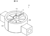
- FIG. 18 is a perspective view of the puncture assisting tool 1E according to the present embodiment.
- the puncture assisting tool 1D includes a second fixing portion 70B instead of the second fixing portion 10B of the puncturing assisting tool 1 in the first embodiment.
- a guide portion 71 is formed in the center of the surface of the second fixing portion 70B facing the first fixing portion 10A along the direction in which the needle N moves (vertical direction in FIG. 18).
- the guide portion 71 has a cylindrical shape in which a through hole 71a through which the needle N passes is formed.
- the second fixing portion 70B is the same as the configuration of the second fixing portion 10B in the first embodiment except that the guide portion 71 is formed.
- the first fixing portion 10A fixed to the first region of the skin S is relative to the second fixing portion 70B fixed to the second region of the skin S.
- tension can be applied to the skin of the region between the first region and the second region. This makes it possible to prevent the skin S from being dented when the needle N is punctured. As a result, the needle N can be punctured without stimulating the nociceptive nerve of the living body.
- the puncture assisting tool 1E since the needle N is guided by the guide portion 71 at the time of puncturing, it is possible to prevent the needle N from buckling. In other words, a needle N having a small outer diameter can be used. As a result, it is possible to suppress stimulation of pain points in the living body.
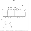
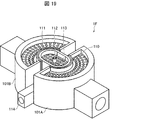
- FIG. 19 is a perspective view of the puncture assisting tool 1F in the present embodiment.
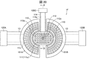
- FIG. 20 is a view of the puncture assisting tool 1F viewed from above in FIG.
- the puncture assisting tool 1F includes a first fixing portion 101A, a second fixing portion 101B, a sticking portion 110, a pump 120A, a pump 120B, and a pump 120C. Note that in FIG. 19, the pumps 120A to 120C are not shown.
- first fixing portion 101A and the second fixing portion 101B have the same configuration as the first fixing portion 10A and the second fixing portion 101B in the first embodiment, the description thereof will be omitted here.
- the exhaust portion 13 of the frame body 11 of the first fixed portion 101A is connected to the pump 120A, and the exhaust portion 13 of the frame body 11 of the second fixed portion 101B is connected to the pump 120B. It is connected.
- the sticking portion 110 is located between the first fixing portion 101A and the second fixing portion 101B.
- the sticking portion 110 includes a frame body 111, a guide portion 112, a support portion 113, and an exhaust portion 114.
- the frame body 111 has a tubular shape.
- the frame body 11 includes one end of the cylinder, a first end 111a which is an end on the side of the living body in contact with the skin, and a second end 111b which is the other end of the cylinder. (See FIG. 21).
- the first end portion 111a has a shape having an opening inside, while the second end portion 111b is a flat plate.
- the frame 111 has a shape in which the surface of the living body in contact with the skin is open.
- an opening 111c is formed on the side surface of the cylinder in a region where the exhaust portion 114 described later is installed (see FIG. 21).
- the guide portion 112 is a member for guiding the movement of the needle N.
- the guide portion 112 has a cylindrical shape, and the cylindrical shaft is the same as the cylindrical shaft of the frame body 11.
- the guide portion 112 is formed with a through hole 112a through which the needle N passes, which is formed along the axial direction of the cylinder (vertical direction in FIG. 19).
- the support 113 is formed inside the frame 111 between the first end 111a and the second end 111b in the cylindrical axial direction (vertical direction in FIG. 19) of the frame 111.
- the support 113 is made of a flat plate.
- a plurality of intake holes 113a are formed in the support 113.
- the exhaust unit 114 is provided on the side surface of the frame 111.
- the exhaust portion 114 is formed with a cylindrical hole 114a. As shown in FIG. 20, one end of the hole 114a is connected to the opening 111c provided in the frame 111, and the other end of the hole 114a is connected to the pump 120C.
- the puncture aid 1F is brought into contact with the skin S of the living body.
- the pump 120A and the pump 120B are driven. As a result, the pressure inside the first fixing portion 101A and the second fixing portion 101B is reduced.
- the inner region (first region) of the first end portion 11a of the frame body 11 of the first fixing portion 101A in the skin S of the living body becomes the first. It is in a state of being attached to the frame 11 of the fixed portion 101A.
- the region inside the first end portion 11a of the frame 11 of the second fixing portion 101B in the skin S of the living body (second region). Is attached to the frame 11 of the second fixing portion 101B.
- the first fixed portion 101A and the second fixed portion 101B are moved in a direction away from each other.
- the region (third region) between the first region and the second region in the skin S of the living body is pulled, and tension is applied to the third region.
- FIG. 21 is a view showing a state when the inside of the frame 111 of the sticking portion 110 is decompressed in puncturing using the puncture assisting tool 1F, and is a cross-sectional view taken along the line DD in FIG. 20.
- the region inside the first end portion 111a of the frame body 111 of the sticking portion 110 (region D4 shown in FIG. 21) in the skin S of the living body. ) Is stuck inside the frame 111.
- the needle N is punctured into the skin S of the living body by moving the syringe (not shown) toward the skin S. Tension is applied to the region where the needle N is punctured. Therefore, it is possible to prevent the skin S from being dented when the needle N is punctured. As a result, the needle N can be punctured without stimulating the nociceptive nerve of the living body.
- the skin S is stuck inside the frame 111 of the sticking portion 110.
- the region where the needle N is punctured is in a state where more tension is applied as compared with the first embodiment, so that the skin S is dented when the needle N is punctured. Can be further prevented.
- the needle N is guided by the guide portion 112 provided on the sticking portion 110 when puncturing. As a result, it is possible to prevent the needle N from buckling. In other words, a needle N having a small outer diameter can be used. As a result, it is possible to suppress stimulation of pain points in the living body.
- the guide portion 112 is arranged inside the region where the skin S is attached in the attachment portion 110.
- the portion where the needle N punctures the skin S of the living body can be the region inside the sticking portion 110 region in the skin S.
- the pumps 120A to 120C are used as suction devices for sucking the air inside the first fixing portion 101A, the second fixing portion 101B, and the sticking portion 110, respectively, but the present invention is not limited to this. ..
- a syringe may be used as the suction device.
- the mechanism used for the puncture aid of the present invention can be used for endoscopic treatment. Specifically, by applying tension to the skin around the tumor formed in an organ of a living body using the first fixing portion and the second fixing portion of the present invention, the tumor is cut and the tumor is inked. Etc. can be easily performed.
- the puncture aid includes a first fixing portion fixed to the first region of the skin and a second fixing portion fixed to the second region of the skin.
- the first fixing portion is movable relative to the second fixing portion so as to pull the skin between the first fixing portion and the second fixing portion.
- the first fixing portion may adsorb the skin.
- the first fixing portion may adhere to or adhere to the skin.
- the first fixing portion may have a spike that is caught on the skin.
- a groove for positioning the needle in a state where the first fixing portion and the second fixing portion are in contact with each other is formed in the first fixing portion. May be good.
- a through hole through which the needle passes is formed, and a guide portion for guiding the movement of the needle may be provided.
- the puncture assisting tool of one aspect of the present invention may include a sticking portion that sticks to the skin, and the guide portion may be arranged inside the sticking region in the sticking portion.
- the first fixing portion may have a support for supporting the skin sucked into the inside of the first fixing portion.
- the puncture assisting tool may include a ventilation portion that is connected to the space inside the first fixing portion and has a bellows structure that shrinks by decompression.
- the puncture aid according to one aspect of the present invention may be provided with a suction device that sucks the air inside the first fixing portion.
- the puncture method according to one aspect of the present invention is a puncture method using any of the above-mentioned puncture aids, in a state where the skin is pulled between the first fixing portion and the second fixing portion. A needle is punctured into the skin between the first fixing portion and the second fixing portion.
Landscapes
- Health & Medical Sciences (AREA)
- Life Sciences & Earth Sciences (AREA)
- Vascular Medicine (AREA)
- Public Health (AREA)
- Hematology (AREA)
- Animal Behavior & Ethology (AREA)
- General Health & Medical Sciences (AREA)
- Engineering & Computer Science (AREA)
- Biomedical Technology (AREA)
- Heart & Thoracic Surgery (AREA)
- Veterinary Medicine (AREA)
- Dermatology (AREA)
- Anesthesiology (AREA)
- Biophysics (AREA)
- Surgery (AREA)
- Molecular Biology (AREA)
- Medical Informatics (AREA)
- Pathology (AREA)
- Physics & Mathematics (AREA)
- Pain & Pain Management (AREA)
- Infusion, Injection, And Reservoir Apparatuses (AREA)
- Surgical Instruments (AREA)
Priority Applications (2)
| Application Number | Priority Date | Filing Date | Title |
|---|---|---|---|
| US17/610,272 US20220218916A1 (en) | 2019-05-14 | 2020-05-14 | Puncture-assistance tool, and puncture method |
| EP20806418.8A EP3970771B1 (en) | 2019-05-14 | 2020-05-14 | Puncture-assistance tool |
Applications Claiming Priority (2)
| Application Number | Priority Date | Filing Date | Title |
|---|---|---|---|
| JP2019091580A JP7267549B2 (ja) | 2019-05-14 | 2019-05-14 | 穿刺補助具 |
| JP2019-091580 | 2019-05-14 |
Publications (1)
| Publication Number | Publication Date |
|---|---|
| WO2020230849A1 true WO2020230849A1 (ja) | 2020-11-19 |
Family
ID=73220827
Family Applications (1)
| Application Number | Title | Priority Date | Filing Date |
|---|---|---|---|
| PCT/JP2020/019270 Ceased WO2020230849A1 (ja) | 2019-05-14 | 2020-05-14 | 穿刺補助具および穿刺方法 |
Country Status (4)
| Country | Link |
|---|---|
| US (1) | US20220218916A1 (enExample) |
| EP (1) | EP3970771B1 (enExample) |
| JP (1) | JP7267549B2 (enExample) |
| WO (1) | WO2020230849A1 (enExample) |
Citations (6)
| Publication number | Priority date | Publication date | Assignee | Title |
|---|---|---|---|---|
| JPS6091804U (ja) * | 1983-11-30 | 1985-06-22 | カルソニックカンセイ株式会社 | 負圧アクチユエ−タ |
| JPS60226317A (ja) * | 1984-04-24 | 1985-11-11 | Nippon Denso Co Ltd | 蛇腹型アクチユエ−タ |
| JP2003516205A (ja) * | 1999-12-10 | 2003-05-13 | アルザ・コーポレーション | 持続した経皮による薬物送達のための皮膚処理装置 |
| JP2009112416A (ja) | 2007-11-02 | 2009-05-28 | Sumitomo Electric Ind Ltd | 穿刺器、バイオセンサ付穿刺器およびバイオセンサ測定装置 |
| JP2010005398A (ja) * | 2008-06-27 | 2010-01-14 | Tyco Healthcare Group Lp | 低プロフィールの器具アクセスデバイス |
| JP2015532180A (ja) * | 2012-10-19 | 2015-11-09 | アムゲン・インコーポレーテッド | 改良された自動注射器 |
Family Cites Families (2)
| Publication number | Priority date | Publication date | Assignee | Title |
|---|---|---|---|---|
| US6743211B1 (en) * | 1999-11-23 | 2004-06-01 | Georgia Tech Research Corporation | Devices and methods for enhanced microneedle penetration of biological barriers |
| US6896666B2 (en) * | 2002-11-08 | 2005-05-24 | Kochamba Family Trust | Cutaneous injection delivery under suction |
-
2019
- 2019-05-14 JP JP2019091580A patent/JP7267549B2/ja active Active
-
2020
- 2020-05-14 US US17/610,272 patent/US20220218916A1/en not_active Abandoned
- 2020-05-14 EP EP20806418.8A patent/EP3970771B1/en active Active
- 2020-05-14 WO PCT/JP2020/019270 patent/WO2020230849A1/ja not_active Ceased
Patent Citations (6)
| Publication number | Priority date | Publication date | Assignee | Title |
|---|---|---|---|---|
| JPS6091804U (ja) * | 1983-11-30 | 1985-06-22 | カルソニックカンセイ株式会社 | 負圧アクチユエ−タ |
| JPS60226317A (ja) * | 1984-04-24 | 1985-11-11 | Nippon Denso Co Ltd | 蛇腹型アクチユエ−タ |
| JP2003516205A (ja) * | 1999-12-10 | 2003-05-13 | アルザ・コーポレーション | 持続した経皮による薬物送達のための皮膚処理装置 |
| JP2009112416A (ja) | 2007-11-02 | 2009-05-28 | Sumitomo Electric Ind Ltd | 穿刺器、バイオセンサ付穿刺器およびバイオセンサ測定装置 |
| JP2010005398A (ja) * | 2008-06-27 | 2010-01-14 | Tyco Healthcare Group Lp | 低プロフィールの器具アクセスデバイス |
| JP2015532180A (ja) * | 2012-10-19 | 2015-11-09 | アムゲン・インコーポレーテッド | 改良された自動注射器 |
Non-Patent Citations (1)
| Title |
|---|
| See also references of EP3970771A4 |
Also Published As
| Publication number | Publication date |
|---|---|
| EP3970771B1 (en) | 2025-07-16 |
| JP2020185190A (ja) | 2020-11-19 |
| US20220218916A1 (en) | 2022-07-14 |
| EP3970771A1 (en) | 2022-03-23 |
| EP3970771A4 (en) | 2023-01-25 |
| JP7267549B2 (ja) | 2023-05-02 |
Similar Documents
| Publication | Publication Date | Title |
|---|---|---|
| US8992439B2 (en) | Medical tool for reduced penetration force | |
| JP3494183B2 (ja) | 簡易採血装置 | |
| CN102510746B (zh) | 鼓膜压力平衡管递送系统 | |
| US8561795B2 (en) | Low-pressure packaging for fluid devices | |
| US5938679A (en) | Apparatus and method for minimally invasive blood sampling | |
| JP5600153B2 (ja) | 減圧下での線状創傷閉合クッションおよびそのシステム | |
| JP2021098096A (ja) | 生物学的組織を採取する方法およびシステム | |
| JP4569971B2 (ja) | 治療用物質の運搬投与器具 | |
| US20120022397A1 (en) | Needle Set for a Biopsy Device and Related Method | |
| DE112009002215T5 (de) | Medizinisches Instrument zur Verringerung der Penetrationskraft mit Mitteln zur Rückkopplung | |
| US11696779B2 (en) | Pericardial gripper and method of implanting a temporary cardiac assist system | |
| KR20170101430A (ko) | 피부 천공 장치용 마이크로 구조체 패치와 이를 구비하는 피부 천공 장치 및 이를 사용하는 피부 천공 방법 | |
| WO2020230849A1 (ja) | 穿刺補助具および穿刺方法 | |
| WO2020230848A1 (ja) | 穿刺補助具、穿刺器具および穿刺方法 | |
| JP4487050B2 (ja) | 体内用医療装置 | |
| KR20210041975A (ko) | 마이크로 니들 시술 장치 | |
| JP2020185189A5 (enExample) | ||
| CN104274230A (zh) | 穿刺致动器 | |
| JP2023013043A (ja) | 超音波下穿刺補助具 | |
| CN113317834A (zh) | 一种手术刀口美观缝合的辅助装置 | |
| JP2002177379A (ja) | 体液吸引補助器具 | |
| JP2020185190A5 (enExample) | ||
| AU2023377793A1 (en) | Microneedle patch delivery applicator and method | |
| CN107735131A (zh) | 使用振动减轻皮肤穿刺的疼痛 | |
| CN120114750A (zh) | 一种仿蚊子脑部柔性电极植入机构 |
Legal Events
| Date | Code | Title | Description |
|---|---|---|---|
| 121 | Ep: the epo has been informed by wipo that ep was designated in this application |
Ref document number: 20806418 Country of ref document: EP Kind code of ref document: A1 |
|
| NENP | Non-entry into the national phase |
Ref country code: DE |
|
| ENP | Entry into the national phase |
Ref document number: 2020806418 Country of ref document: EP Effective date: 20211214 |
|
| WWG | Wipo information: grant in national office |
Ref document number: 2020806418 Country of ref document: EP |