WO2020230724A1 - パターン構造含有シートの製造方法 - Google Patents
パターン構造含有シートの製造方法 Download PDFInfo
- Publication number
- WO2020230724A1 WO2020230724A1 PCT/JP2020/018687 JP2020018687W WO2020230724A1 WO 2020230724 A1 WO2020230724 A1 WO 2020230724A1 JP 2020018687 W JP2020018687 W JP 2020018687W WO 2020230724 A1 WO2020230724 A1 WO 2020230724A1
- Authority
- WO
- WIPO (PCT)
- Prior art keywords
- pattern
- base material
- less
- group
- fibrous cellulose
- Prior art date
- Legal status (The legal status is an assumption and is not a legal conclusion. Google has not performed a legal analysis and makes no representation as to the accuracy of the status listed.)
- Ceased
Links
Images



Classifications
-
- B—PERFORMING OPERATIONS; TRANSPORTING
- B05—SPRAYING OR ATOMISING IN GENERAL; APPLYING FLUENT MATERIALS TO SURFACES, IN GENERAL
- B05D—PROCESSES FOR APPLYING FLUENT MATERIALS TO SURFACES, IN GENERAL
- B05D1/00—Processes for applying liquids or other fluent materials
- B05D1/32—Processes for applying liquids or other fluent materials using means for protecting parts of a surface not to be coated, e.g. using stencils, resists
-
- B—PERFORMING OPERATIONS; TRANSPORTING
- B05—SPRAYING OR ATOMISING IN GENERAL; APPLYING FLUENT MATERIALS TO SURFACES, IN GENERAL
- B05D—PROCESSES FOR APPLYING FLUENT MATERIALS TO SURFACES, IN GENERAL
- B05D3/00—Pretreatment of surfaces to which liquids or other fluent materials are to be applied; After-treatment of applied coatings, e.g. intermediate treating of an applied coating preparatory to subsequent applications of liquids or other fluent materials
- B05D3/06—Pretreatment of surfaces to which liquids or other fluent materials are to be applied; After-treatment of applied coatings, e.g. intermediate treating of an applied coating preparatory to subsequent applications of liquids or other fluent materials by exposure to radiation
-
- B—PERFORMING OPERATIONS; TRANSPORTING
- B05—SPRAYING OR ATOMISING IN GENERAL; APPLYING FLUENT MATERIALS TO SURFACES, IN GENERAL
- B05D—PROCESSES FOR APPLYING FLUENT MATERIALS TO SURFACES, IN GENERAL
- B05D5/00—Processes for applying liquids or other fluent materials to surfaces to obtain special surface effects, finishes or structures
- B05D5/12—Processes for applying liquids or other fluent materials to surfaces to obtain special surface effects, finishes or structures to obtain a coating with specific electrical properties
-
- B—PERFORMING OPERATIONS; TRANSPORTING
- B05—SPRAYING OR ATOMISING IN GENERAL; APPLYING FLUENT MATERIALS TO SURFACES, IN GENERAL
- B05D—PROCESSES FOR APPLYING FLUENT MATERIALS TO SURFACES, IN GENERAL
- B05D7/00—Processes, other than flocking, specially adapted for applying liquids or other fluent materials to particular surfaces or for applying particular liquids or other fluent materials
-
- B—PERFORMING OPERATIONS; TRANSPORTING
- B05—SPRAYING OR ATOMISING IN GENERAL; APPLYING FLUENT MATERIALS TO SURFACES, IN GENERAL
- B05D—PROCESSES FOR APPLYING FLUENT MATERIALS TO SURFACES, IN GENERAL
- B05D7/00—Processes, other than flocking, specially adapted for applying liquids or other fluent materials to particular surfaces or for applying particular liquids or other fluent materials
- B05D7/24—Processes, other than flocking, specially adapted for applying liquids or other fluent materials to particular surfaces or for applying particular liquids or other fluent materials for applying particular liquids or other fluent materials
-
- B—PERFORMING OPERATIONS; TRANSPORTING
- B32—LAYERED PRODUCTS
- B32B—LAYERED PRODUCTS, i.e. PRODUCTS BUILT-UP OF STRATA OF FLAT OR NON-FLAT, e.g. CELLULAR OR HONEYCOMB, FORM
- B32B27/00—Layered products comprising a layer of synthetic resin
- B32B27/12—Layered products comprising a layer of synthetic resin next to a fibrous or filamentary layer
-
- B—PERFORMING OPERATIONS; TRANSPORTING
- B32—LAYERED PRODUCTS
- B32B—LAYERED PRODUCTS, i.e. PRODUCTS BUILT-UP OF STRATA OF FLAT OR NON-FLAT, e.g. CELLULAR OR HONEYCOMB, FORM
- B32B27/00—Layered products comprising a layer of synthetic resin
- B32B27/16—Layered products comprising a layer of synthetic resin specially treated, e.g. irradiated
-
- D—TEXTILES; PAPER
- D21—PAPER-MAKING; PRODUCTION OF CELLULOSE
- D21H—PULP COMPOSITIONS; PREPARATION THEREOF NOT COVERED BY SUBCLASSES D21C OR D21D; IMPREGNATING OR COATING OF PAPER; TREATMENT OF FINISHED PAPER NOT COVERED BY CLASS B31 OR SUBCLASS D21G; PAPER NOT OTHERWISE PROVIDED FOR
- D21H11/00—Pulp or paper, comprising cellulose or lignocellulose fibres of natural origin only
- D21H11/16—Pulp or paper, comprising cellulose or lignocellulose fibres of natural origin only modified by a particular after-treatment
- D21H11/18—Highly hydrated, swollen or fibrillatable fibres
-
- D—TEXTILES; PAPER
- D21—PAPER-MAKING; PRODUCTION OF CELLULOSE
- D21H—PULP COMPOSITIONS; PREPARATION THEREOF NOT COVERED BY SUBCLASSES D21C OR D21D; IMPREGNATING OR COATING OF PAPER; TREATMENT OF FINISHED PAPER NOT COVERED BY CLASS B31 OR SUBCLASS D21G; PAPER NOT OTHERWISE PROVIDED FOR
- D21H11/00—Pulp or paper, comprising cellulose or lignocellulose fibres of natural origin only
- D21H11/16—Pulp or paper, comprising cellulose or lignocellulose fibres of natural origin only modified by a particular after-treatment
- D21H11/20—Chemically or biochemically modified fibres
-
- H—ELECTRICITY
- H05—ELECTRIC TECHNIQUES NOT OTHERWISE PROVIDED FOR
- H05K—PRINTED CIRCUITS; CASINGS OR CONSTRUCTIONAL DETAILS OF ELECTRIC APPARATUS; MANUFACTURE OF ASSEMBLAGES OF ELECTRICAL COMPONENTS
- H05K1/00—Printed circuits
- H05K1/02—Details
- H05K1/03—Use of materials for the substrate
Definitions
- the present invention relates to a method for producing a sheet containing a pattern structure. Specifically, the present invention relates to a method for producing a pattern structure-containing sheet, which comprises a step of forming a pattern on a pattern-forming base material containing fine fibrous cellulose.
- fibrous cellulose having a fiber diameter of 10 ⁇ m or more and 50 ⁇ m or less, particularly fibrous cellulose (pulp) derived from wood, has been widely used mainly as paper products.
- fine fibrous cellulose having a fiber diameter of 1 ⁇ m or less is also known. Further, a sheet composed of such fine fibrous cellulose and a composite containing a fine fibrous cellulose-containing sheet and a resin layer have been developed. Then, it is also considered to use such a sheet or a composite as an optical member.
- Patent Documents 1 to 4 disclose that a composite sheet is formed by impregnating a sheet containing fine fibrous cellulose with a resin component, and the composite sheet is used for a wiring board or a circuit board.
- Patent Document 5 discloses a cellulose fiber composite film containing a cellulose fiber and a low molecular weight lubricant, and it is considered to use such a composite film as a wiring substrate.
- Patent Document 6 discloses a vacuum ultraviolet light irradiation device including a lamp housing that emits light including vacuum ultraviolet light and other predetermined structures.
- Japanese Unexamined Patent Publication No. 2005-060680 Japanese Unexamined Patent Publication No. 2016-089022 JP-A-2018-132655 JP-A-2018-170518 JP-A-2017-0781151 JP 2015-126044
- the present inventors have developed a method for producing a pattern structure-containing sheet capable of forming a highly accurate pattern on a pattern-forming substrate containing fine fibrous cellulose. We proceeded with the study for the purpose of providing it.
- the present inventors have put a pattern on a pattern-forming base material having a base layer containing fibrous cellulose having a fiber width of 1000 nm or less and a resin layer. It has been found that a highly accurate pattern is formed by irradiating a photomask for formation with vacuum ultraviolet rays and further imparting a conductive material to the vacuum ultraviolet rays irradiated portion.
- the present invention has the following configuration.
- a method for producing a pattern structure-containing sheet which comprises a step of applying a conductive material to a vacuum ultraviolet irradiation portion on a pattern forming base material to form a pattern.
- [3] The method for producing a pattern structure-containing sheet according to [1] or [2], wherein the step of irradiating the vacuum ultraviolet rays is a step of irradiating the vacuum ultraviolet rays as parallel light.
- [5] The method for producing a pattern structure-containing sheet according to any one of [1] to [4], wherein the base layer containing fibrous cellulose further contains a hydrophilic polymer.
- a pattern structure-containing sheet in which a highly accurate pattern is formed can be obtained.
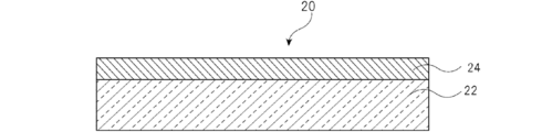
- FIG. 1 is a cross-sectional view illustrating the configuration of a base material for pattern formation.
- FIG. 2 is a schematic view illustrating the configuration of a vacuum ultraviolet light irradiation processing apparatus used in the method for producing a pattern structure-containing sheet of the present invention.
- FIG. 3 is a cross-sectional view illustrating the configuration of the pattern structure-containing sheet obtained by the method for producing the pattern structure-containing sheet of the present invention.
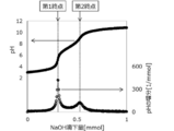
- FIG. 4 is a graph showing the relationship between the amount of NaOH added dropwise and the pH of the fibrous cellulose-containing slurry having a phosphorus oxo acid group.
- FIG. 5 is a graph showing the relationship between the amount of NaOH added dropwise to the fibrous cellulose-containing slurry having a carboxy group and the pH.
- the present invention relates to a method for producing a sheet containing a pattern structure.
- a photomask for pattern formation is placed on an upper part of a base material for pattern formation having a base layer containing fibrous cellulose having a fiber width of 1000 nm or less and a resin layer. It includes a step of irradiating the vacuum ultraviolet rays and a step of applying a conductive material to the vacuum ultraviolet rays irradiation portion on the pattern forming base material to form a pattern.
- a highly accurate pattern is formed on the pattern structure-containing sheet obtained through such a manufacturing process.
- a photomask for pattern formation is placed on an upper portion of a pattern forming base material having a base layer containing fibrous cellulose having a fiber width of 1000 nm or less and a resin layer. It includes a step of irradiating vacuum ultraviolet rays.
- a pattern-forming base material is installed at a predetermined position of the vacuum ultraviolet light irradiation processing device, and vacuum ultraviolet rays are irradiated from above the photomask placed on the pattern-forming base material.
- vacuum ultraviolet rays are ultraviolet rays having a wavelength of 200 nm or less, and may be referred to as VUV. The wavelength of the vacuum ultraviolet light may be 160 nm or more.
- FIG. 1 is a cross-sectional view illustrating the configuration of a pattern forming base material used in the method for producing a pattern structure-containing sheet of the present invention.
- the pattern-forming base material 20 has a base layer 22 containing fine fibrous cellulose and a resin layer 24.
- the base layer 22 and the resin layer 24 are laminated so as to be in contact with each other on one of the surfaces.
- the pattern-forming base material may have at least one base layer 22 and one resin layer 24, but may have two or more base layers 22 and two or more resin layers 24. It may be.
- the structure may have resin layers 24 on both sides of the base layer 22.
- fibrous cellulose having a fiber width of 1000 nm or less may be referred to as fine fibrous cellulose or CNF.
- FIG. 2 is a schematic view illustrating the configuration of the vacuum ultraviolet light irradiation processing apparatus used in the method for producing a pattern structure-containing sheet of the present invention.
- the vacuum ultraviolet light irradiation processing device 100 includes a processing chamber 5 in which a lamp housing 3, a transmissive window portion 4, and a work stage 7 for installing a pattern forming base material 20 are arranged inside. And.
- the lamp housing 3 and the processing chamber 5 are connected to each other via a transparent window portion 4 so as to maintain airtightness.
- the structure may be such that the lamp housing 3 irradiates the processing chamber 5 with vacuum ultraviolet rays, and it is preferable that the lamp housing 3 is provided above the processing chamber 5.
- VUV-SFL VUV short arc flash lamp 1
- the flash lamp 1 VUV-SFL
- the power feeding means 11 includes a capacitor for charging energy, a power supply unit 13 including a step-up transformer, a trigger circuit unit 12 for generating a trigger pulse for starting, and a charger 14 for charging the capacitor of the power supply unit 13, and is a small power source.
- the unit 13 and the trigger circuit unit 12 may be installed inside the lamp housing 3.
- the light emitted from the flash lamp 1 is made parallel by the parabolic mirror 2, passes through the transmissive window portion 4, and is applied to the pattern forming base material 20 installed in the processing chamber 5. That is, the step of irradiating the vacuum ultraviolet rays is preferably a step of irradiating the pattern forming base material 20 with the vacuum ultraviolet rays as parallel light.
- the parallel light means light emitted in parallel with the optical axis of the reflecting mirror, and when applied to the present device 100, the parallel light is parallel light because the reflecting mirror is a parabolic mirror. Is emitted. Then, the emitted parallel light irradiates the surface of the pattern forming base material 20 installed in the processing chamber 5 at the same angle.
- the parallel light is light emitted in the direction perpendicular to the surface of the pattern forming base material 20.
- the parallel light includes substantially parallel light.
- the transmissive window portion 4 has a high transmittance for vacuum ultraviolet rays (VUV). Further, the transparent window portion 4 is assembled so that the airtightness of each of the lamp housing 3 and the processing chamber 5 is maintained, and the inside of the lamp housing 3 via the transparent window portion 4 is transferred to the processing chamber 5. There is no gas permeation.
- the lamp housing 3 is introduced an inert gas purge from the first gas inlet port 3a provided in the lamp housing 3, such as N 2 gas.
- the inert gas such as N 2 gas introduced into the lamp housing 3 is a through hole at the top of the power supply unit 11, the trigger circuit unit 12, the parabolic mirror 2, and the parabolic mirror 2 of the power feeding means 11 and the flash lamp. 1
- the flash lamp 1 is reached through a gap between the outer surface and the flash lamp 1, and after cooling these, the flash lamp 1 is exhausted from the first exhaust port 3b provided in the lamp housing 3.
- At least one or more passage holes 3c that spatially connect the internal space of the lamp housing 3 and the inside of the processing stage 5 may be provided around the transparent window portion 4 of the lamp housing 3.
- the photomask 6 installs a mask upper space A, which is a space between the transparent window portion 4 and the photomask 6, and a pattern forming base material 20 on the lower surface of the photomask 6. It is divided into a work processing space B. Therefore, the passage hole 3c spatially connects the inside of the lamp housing 3 and the mask upper space A, but the mask upper space A and the work processing space B do not communicate with each other.
- a second exhaust port 5a is provided in the mask upper space A.
- a work stage 7 in which the pattern forming base material 20 is installed is provided in the processing chamber 5.
- the resin layer 24 of the pattern forming base material 20 is installed on the work stage 7 so as to be the upper surface (exposed surface).
- a photomask 6 having a transfer pattern is arranged between the pattern-forming base material 20 and the transparent window portion 4. ..
- the photomask 6 is provided with, for example, a metal thin film or the like as a member made of a material that does not transmit vacuum ultraviolet rays (VUV) on one surface of a material that transmits vacuum ultraviolet rays (VUV).
- An intermittent portion for transmitting vacuum ultraviolet rays (VUV) is provided in the portion.
- the photomask 6 may be a metal mask in which an intermittent portion is formed on the metal material by processing such as etching. As a result, a part of the parallel light emitted from the lamp housing 3 passes through the intermittent portion of the photomask 6 and reaches the pattern forming base material 20.
- the work processing space B of the processing chamber 5 is under atmospheric conditions, oxygen is present in the work processing space B. That is, oxygen is present between the above-mentioned photomask 6 and the pattern-forming base material 20.
- a gas containing oxygen may be introduced into the work processing space B from the second gas introduction port 5b, the work processing space B may be purged by the gas, and the gas may be exhausted from the third gas exhaust port 5c. ..
- VUV vacuum ultraviolet rays
- the vacuum ultraviolet irradiation portion of the resin layer 24 is formed according to the pattern shape of the intermittent portion of the photomask 6, and this vacuum ultraviolet irradiation portion is a portion that has been liquefied by irradiation with vacuum ultraviolet (VUV).
- VUV vacuum ultraviolet
- the liquefaction of the resin layer 24 in the pattern forming base material 20 can be determined by measuring the solution contact angle of the exposed portion on the surface of the pattern forming base material 20 irradiated with vacuum ultraviolet rays (VUV). For example, when the resin layer 24 in the pattern-forming base material 20 becomes hydrophilic by irradiation with vacuum ultraviolet rays (VUV), the water contact on the surface of the pattern-forming base material 20 is measured to obtain hydrophilicity (parent liquefaction). It can be determined that it has been done.
- VUV vacuum ultraviolet rays
- the resin layer 24 in the pattern-forming base material 20 is hydrophilic (liquidation). Can be determined.
- the water contact angle on the surface of the pattern forming base material 20 is preferably 40 ° or less, and more preferably 30 ° or less.
- the water contact angle on the surface of the pattern forming base material is the water contact angle of the exposed portion on the surface of the resin layer of the pattern forming base material.
- the water contact angle on the surface of the pattern-forming base material is the water contact angle 5 seconds after dropping 1 ⁇ L of distilled water onto the surface of the pattern-forming base material.
- a dynamic water contact angle tester is used for the measurement.
- the dynamic water contact angle tester for example, 1100 DAT manufactured by Fibro can be used.
- a tape-shaped gap constituent member may be sandwiched between the photomask 6 and the pattern-forming base material 20 to form a gap.
- vacuum ultraviolet light irradiation processing device 100 for example, a VUV patterning experimental machine SUS740 manufactured by Ushio, Inc. can be used.
- a conductive material is applied to the vacuum ultraviolet rays irradiation portion on the pattern forming base material. It includes a step of imparting and forming a pattern.
- the conductive material is applied onto the exposed pattern forming base material 20. It is preferable that the conductive material is applied after the pattern-forming base material 20 is taken out from the exposure apparatus.
- a method for applying the conductive material various methods such as a coating method, a spraying method, and an impregnation method can be adopted. Above all, it is preferable to impart the conductive material by a coating method.
- a coating device for example, a blade coater, an air knife coater, a roll coater, a bar coater, a gravure coater, a micro gravure coater, a rod blade coater and the like can be used.
- the conductive material examples include a metal-containing composition, a conductive polymer-containing composition, and the like.
- the conductive material may be a material having conductivity, or may be a material capable of acquiring conductivity in the process of forming a pattern structure.
- examples of the metal contained in the metal-containing composition include Ag, Au, Cu, Al, Fe, Zn, Ni, Cr, and Mo.
- the metal-containing composition may be a composition containing the above-mentioned metal oxide.
- the metal-containing composition may contain additives such as a solvent and a dispersant, and as the metal-containing composition, for example, a metal ink, a metal paste, or the like can be used, and a metal nanoparticle ink can be used. Etc. can also be used.
- the conductive polymer contained in the conductive polymer-containing composition includes, for example, a polythiophene-based conductive polymer, a polypyrrole-based conductive polymer, and polyaniline.
- examples thereof include based conductive polymers, poly (p-phenylene vinylene) based conductive polymers, polykinoxaline based conductive polymers and the like.
- a polythiophene-based conductive polymer is preferable from the viewpoint of having a good balance of optical properties, appearance, antistatic property, coatability, stability and the like.
- the polythiophene-based conductive polymer include polyethylenedioxythiophene and polythiophene. These conductive polymers may be used alone or in combination of two or more.
- the vacuum on the pattern forming base material 20 is applied. It is preferable to include a step of removing the conductive material from a region other than the ultraviolet irradiation portion. As a result, the conductive material is applied only to the vacuum ultraviolet irradiation portion of the pattern forming base material 20.
- the coating thickness of the conductive material is preferably 0.1 ⁇ m or more, more preferably 1 ⁇ m or more, and further preferably 2 ⁇ m or more. Further, the coating thickness of the conductive material is preferably 50 ⁇ m or less, and more preferably 30 ⁇ m or less.
- a drying step may be provided.
- the drying temperature at this time is preferably 50 ° C. or higher, more preferably 60 ° C. or higher, and even more preferably 70 ° C. or higher.
- the drying temperature is preferably 200 ° C. or lower, more preferably 180 ° C. or lower, and even more preferably 160 ° C. or lower.
- the drying time in the drying step is preferably 1 minute or longer, more preferably 2 minutes or longer.
- the drying time is preferably 60 minutes or less, more preferably 40 minutes or less.
- FIG. 3 is a cross-sectional view illustrating the configuration of the pattern structure-containing sheet 50 obtained by the method for producing a pattern structure-containing sheet of the present invention.
- a vacuum ultraviolet irradiation unit 52 (parent liquefaction unit) is formed on the resin layer 24 of the pattern forming base material 20, and the vacuum ultraviolet irradiation unit 52 A conductive portion 54 made of a conductive material is laminated on the top.
- the thickness and the ratio of the thickness of each layer are not necessarily the same as the actual configuration of the pattern structure-containing sheet. Absent.
- the thinnest line is the width of the thinnest line in the pattern structure formed on the pattern forming base material 20.
- the width of the thinnest line is the width shown as L in FIG.
- the width of the space in the pattern is shown as S in FIG.
- the width of the thinnest line among the pattern structures formed on the pattern forming base material 20 can be appropriately adjusted depending on the intended use, but forms a fine line structure such as 50 ⁇ m or less, 40 ⁇ m or less, and 30 ⁇ m or less. It is also possible.
- the width of the narrowest space can be appropriately adjusted depending on the application, but it is possible to form a fine space structure such as 50 ⁇ m or less, 40 ⁇ m or less, and 30 ⁇ m or less.
- the width of the thinnest line and the width of the thinnest space are preferably 1 ⁇ m or more, respectively.
- the width of the thinnest line on the pattern forming base material 20 can be measured by observing an optical microscope.
- the pattern-forming base material used in the method for producing a pattern structure-containing sheet of the present invention includes a base layer containing fibrous cellulose having a fiber width of 1000 nm or less, and a resin layer.
- FIG. 1 is a cross-sectional view illustrating the configuration of a pattern forming base material 20 used in the method for producing a pattern structure-containing sheet of the present invention. As shown in FIG. 1, the pattern-forming base material 20 has a base layer 22 containing fine fibrous cellulose and a resin layer 24.
- the dimensional stability of the pattern-forming base material 20 can be enhanced, thereby increasing the height.
- An accurate pattern structure can be formed.
- the overall thickness of the pattern-forming substrate is not particularly limited, but is preferably 10 ⁇ m or more, more preferably 20 ⁇ m or more, and even more preferably 30 ⁇ m or more.
- the total thickness of the pattern-forming substrate is preferably 1000 mm or less, more preferably 700 ⁇ m or less, and even more preferably 500 ⁇ m or less. It is preferable that the thickness of the base material for pattern formation is appropriately adjusted according to the shape of the pattern to be formed and its use.
- the thickness of the base layer of the pattern-forming base material is preferably 5 ⁇ m or more, more preferably 10 ⁇ m or more, and further preferably 15 ⁇ m or more.
- the thickness of the base layer is preferably 995 ⁇ m or less, more preferably 695 ⁇ m or less, and further preferably 495 ⁇ m or less.
- the thickness of the base layer constituting the pattern-forming base material is determined by cutting out a cross section of the pattern-forming base material with an ultramicrotome UC-7 (manufactured by JEOL Ltd.) and observing the cross section with an electron microscope, a magnifying glass or visually. Then, it is a value to be measured.
- the total thickness of the base layers is preferably within the above range.
- the thickness of the resin layer of the pattern-forming base material is preferably 0.1 ⁇ m or more, and more preferably 1 ⁇ m or more.
- the thickness of the resin layer is preferably 20 ⁇ m or less, more preferably 15 ⁇ m or less, and even more preferably 10 ⁇ m or less.
- the thickness of the resin layer constituting the pattern-forming base material is determined by cutting out a cross section of the pattern-forming base material with an ultramicrotome UC-7 (manufactured by JEOL Ltd.) and visually recognizing the cross section with an electron microscope, a magnifying glass, or visually. It is a value that is observed and measured.
- the pattern-forming base material contains a plurality of resin layers, the total thickness of the resin layers is preferably within the above range.
- the density of the pattern forming substrate is preferably 1.00 g / cm 3 or more, more preferably 1.10 g / cm 3 or more, more preferably 1.20 g / cm 3 or more.
- the density of the pattern-forming base material was calculated by dividing the basis weight of the pattern-forming base material by the thickness.
- the thickness of the base material for pattern formation can be measured with a stylus type thickness gauge (Millitron 1202D manufactured by Marl Co., Ltd.).
- the total light transmittance of the pattern forming base material is preferably 60% or more, more preferably 70% or more, further preferably 80% or more, and particularly preferably 90% or more.
- the total light transmittance is a value measured using a haze meter (manufactured by Murakami Color Technology Research Institute, HM-150) in accordance with JIS K7361.
- the haze of the base material for pattern formation is preferably 10.0% or less, more preferably 5.0% or less, further preferably 2.5% or less, further preferably 2.0% or less, and 1.5% or less. Even more preferably, 1.0% or less is particularly preferable.
- the haze is a value measured using a haze meter (manufactured by Murakami Color Technology Research Institute, HM-150) in accordance with JIS K7136.
- the tensile elastic modulus of the pattern-forming substrate at 23 ° C. and 50% relative humidity is preferably 2.5 GPa or more, more preferably 3.0 GPa or more, and further preferably 5.0 GPa or more. , 7.0 GPa or more, more preferably 8.0 GPa or more, and particularly preferably 9.0 GPa or more. Further, the tensile elastic modulus of the pattern-forming base material at 23 ° C. and 50% relative humidity is preferably 30 GPa or less.
- the tensile elastic modulus of the pattern-forming substrate is a value measured in accordance with JIS P 8113, and the tensile elastic modulus is a value calculated from the maximum positive inclination value in the SS curve (stress-strain curve). Is.
- the shrinkage rate is preferably less than 1.5%, more preferably 1.2% or less. It is more preferably 0% or less, further preferably 0.8% or less, and particularly preferably 0.7% or less.
- the shrinkage rate of the pattern-forming base material is set to 20 mm between chucks, a load of 10 g, and a nitrogen atmosphere in a tension mode after setting a pattern-forming base material having a width of 3 mm and a length of 30 mm in a thermomechanical analyzer.
- Shrinkage rate (%)
- the coefficient of linear thermal expansion of the pattern-forming substrate is preferably 50 ppm / K or less. It is more preferably 40 ppm / K or less, and further preferably 30 ppm / K or less.
- the coefficient of linear thermal expansion of the pattern-forming base material is 4 mm wide x 30 mm long, after the pattern-forming base material is set in a thermomechanical analyzer (TMA7100, manufactured by Hitachi High-Tech), the chuck distance is 20 mm and the load is 10 g in the pull mode. It is a value calculated from the measured values of 100 ° C. to 150 ° C. when the temperature is raised from room temperature to 180 ° C. at 5 ° C./min and lowered from 180 ° C. to 25 ° C. at 5 ° C./min under a nitrogen atmosphere.
- the surface roughness (arithmetic mean) of the pattern-forming substrate is preferably 10 nm or less, more preferably 8 nm or less, further preferably 6 nm or less, and particularly preferably 4 nm or less.
- the surface roughness (arithmetic mean) of the pattern-forming base material is the arithmetic mean roughness of the surface of the resin layer of the pattern-forming base material.
- the surface roughness (arithmetic mean) is a value obtained by measuring the arithmetic mean roughness of 10 ⁇ m square using an atomic force microscope (NanoScop IIIa manufactured by Veeco).
- the water contact angle on the surface of the pattern forming base material is preferably 60 ° or more, more preferably 65 ° or more, and even more preferably 70 ° or more.
- the water contact angle on the surface of the pattern-forming base material is the water contact angle on the surface of the resin layer of the pattern-forming base material.
- the water contact angle on the surface of the pattern-forming base material is the water contact angle 30 seconds after dropping 4 ⁇ L of distilled water onto the surface of the pattern-forming base material.
- a dynamic water contact angle tester is used for the measurement.
- the dynamic water contact angle tester for example, 1100 DAT manufactured by Fibro can be used.
- the water contact angle on the surface of the pattern-forming base material after irradiating the pattern-forming base material with vacuum ultraviolet rays (VUV) for 5 minutes is preferably 50 ° or less, more preferably 40 ° or less. , 30 ° or less is more preferable.
- VUV vacuum ultraviolet rays
- the water contact angle is a value at the vacuum ultraviolet (VUV) irradiation portion on the surface of the pattern forming base material.
- the resin layer is a layer containing a natural resin or a synthetic resin as a main component.
- the main component refers to a component contained in an amount of 50% by mass or more with respect to the total mass of the resin layer.
- the content of the resin is preferably 60% by mass or more, more preferably 70% by mass or more, further preferably 80% by mass or more, and 90% by mass, based on the total mass of the resin layer. The above is particularly preferable.
- the resin content may be 100% by mass or 95% by mass or less.
- Examples of the natural resin include rosin-based resins such as rosin, rosin ester, and hydrogenated rosin ester.
- the synthetic resin is preferably at least one selected from, for example, polycarbonate resin, polyethylene terephthalate resin, polyethylene naphthalate resin, polyethylene resin, polypropylene resin, polyimide resin, polystyrene resin, urethane resin and acrylic resin.
- the synthetic resin is preferably at least one selected from the polycarbonate resin, the urethane resin and the acrylic resin, and more preferably at least one selected from the urethane resin and the acrylic resin.
- the acrylic resin is preferably at least one selected from polyacrylonitrile, poly (meth) acrylate and urethane acrylate.
- polycarbonate resin constituting the resin layer examples include aromatic polycarbonate-based resin and aliphatic polycarbonate-based resin. These specific polycarbonate-based resins are known, and examples thereof include the polycarbonate-based resins described in JP-A-2010-023275.
- the resin layer preferably contains a hydrophobic resin.
- a hydrophobic resin is defined as a resin having a contact angle with water of 60 degrees or more in a dry state.
- in a dry state means excluding a state in which the hydrophobic resin has an affinity for water, such as when it is in an emulsion state.
- the resin layer may contain an adhesion aid.
- the adhesion aid include a compound containing at least one selected from an isocyanate group, a carbodiimide group, an epoxy group, an oxazoline group, an amino group and a silanol group, and an organosilicon compound.
- the adhesion aid is preferably at least one selected from a compound containing an isocyanate group (isocyanate compound) and an organosilicon compound.
- the organosilicon compound include a silane coupling agent condensate and a silane coupling agent.
- Examples of the isocyanate compound include polyfunctional isocyanates which are polyisocyanate compounds or more.
- Specific examples of the polyisocyanate compound include aromatic polyisocyanates having 6 to 20 carbon atoms excluding carbon in the NCO group, aliphatic polyisocyanates having 2 to 18 carbon atoms, and 6 to 15 carbon atoms. Aliphatic polyisocyanates, aralkyl-type polyisocyanates having 8 or more and 15 or less carbon atoms, modified products of these polyisocyanates, and mixtures of two or more of these can be mentioned. Among them, an alicyclic polyisocyanate having 6 to 15 carbon atoms, that is, isocyanurate is preferably used.
- alicyclic polyisocyanate examples include isophorone diisocyanate (IPDI), dicyclohexylmethane-4,4'-diisocyanate (hydrogenated MDI), cyclohexylene diisocyanate, methylcyclohexylene diisocyanate, and bis (2-isocyanatoethyl).
- IPDI isophorone diisocyanate
- MDI dicyclohexylmethane-4,4'-diisocyanate
- cyclohexylene diisocyanate methylcyclohexylene diisocyanate
- bis (2-isocyanatoethyl examples include -4-cyclohexene-1,2-dicarboxylate, 2,5-norbornandiisocyanate and 2,6-norbornandiisocyanate.
- the organosilicon compound examples include a compound having a siloxane structure and a compound that forms a siloxane structure by condensation.
- a silane coupling agent or a condensate of a silane coupling agent can be mentioned.
- the silane coupling agent may have a functional group other than the alkoxysilyl group, or may have no other functional group.
- the functional group other than the alkoxysilyl group include a vinyl group, an epoxy group, a styryl group, a methacryloxy group, an acryloxy group, an amino group, a ureido group, a mercapto group, a sulfide group and an isocyanate group.
- the silane coupling agent used in the present invention is preferably a silane coupling agent containing a methacryloxy group.
- the silane coupling agent having a methacryloxy group in the molecule include methacryloxypropylmethyldimethoxysilane, methacryloxypropyltrimethoxysilane, methacryloxypropylmethyldiethoxysilane, and methacryloxypropyltriethoxysilane.
- examples thereof include 1,3-bis (3-methacryloxypropyl) tetramethyldisiloxane.
- at least one selected from methacryloxypropyltrimethoxysilane, methacryloxypropyltriethoxysilane and 1,3-bis (3-methacryloxypropyl) tetramethyldisiloxane is preferably used.
- the silane coupling agent preferably contains three or more alkoxysilyl groups.
- silanol groups are generated after hydrolysis, and at least a part of silanol groups is present even after the base layer is laminated. Since the silanol group is a hydrophilic group, it is possible to improve the adhesion between the resin layer and the base layer by increasing the hydrophilicity of the surface of the resin layer on the base layer side.
- the adhesion aid may be contained in a state of being uniformly dispersed in the resin layer.
- the state in which the adhesion aid is uniformly dispersed in the resin layer means that the concentrations in the following three regions ((a) to (c)) are measured and the concentrations in any of the two regions are compared. A state in which there is no difference of 2 times or more.
- (A) Region from the surface of the resin layer on the base layer side to 10% of the total thickness of the resin layer (b) From the surface of the resin layer opposite to the surface on the base layer side to 10% of the total thickness of the resin layer Region (c) A region of ⁇ 5% (total 10%) of the total thickness from the central surface in the thickness direction of the resin layer.
- the adhesion aid may be unevenly distributed in the region on the base layer side of the resin layer.
- the organosilicon compound may be unevenly distributed in the region on the base layer side of the resin layer.
- the state of being unevenly distributed in the region on the base layer side of the resin layer means that the two concentrations of the following regions ((d) and (e)) are measured and the difference between these concentrations is more than twice. The state of being out.
- D Region from the surface of the resin layer on the base layer side to 10% of the total thickness of the resin layer
- e Region of ⁇ 5% (total 10%) of the total thickness from the central surface in the thickness direction of the resin layer.
- the concentration of the adhesion aid is a numerical value measured by an X-ray electron spectroscope or an infrared spectrophotometer, and is a cross section of a predetermined region of the pattern forming substrate by Ultramicrotome UC-7 (manufactured by JEOL). It is a value obtained by cutting out and measuring the cross section with the device.
- An organosilicon compound-containing layer may be provided on the surface of the resin layer on the base layer side, and such a state is also included in a state in which the organosilicon compounds are unevenly distributed in the region on the base layer side of the resin layer.
- the organosilicon compound-containing layer may be a coating layer formed by applying an organosilicon compound-containing coating liquid.
- the content of the adhesion aid is preferably 0.1 part by mass or more, and more preferably 0.5 part by mass or more with respect to 100 parts by mass of the resin contained in the resin layer.
- the content of the adhesion aid is preferably 40 parts by mass or less, and more preferably 35 parts by mass or less, based on 100 parts by mass of the resin contained in the resin layer.
- the content of the isocyanate compound is preferably 10 parts by mass or more, more preferably 15 parts by mass or more, based on 100 parts by mass of the resin contained in the resin layer. It is more preferably 18 parts by mass or more.
- the content of the isocyanate compound is preferably 40 parts by mass or less, more preferably 35 parts by mass or less, and more preferably 30 parts by mass or less with respect to 100 parts by mass of the resin contained in the resin layer. More preferred.
- the adhesion aid is an organosilicon compound
- the content of the organosilicon compound is preferably 0.1 part by mass or more, preferably 0.5 part by mass or more, based on 100 parts by mass of the resin contained in the resin layer. More preferably.
- the content of the organosilicon compound is preferably 10 parts by mass or less, and more preferably 5 parts by mass or less, based on 100 parts by mass of the resin contained in the resin layer.
- the content of the isocyanate group contained in the resin layer is preferably 0.5 mmol / g or more, more preferably 0.6 mmol / g or more, and 0.8 mmol or more. It is more preferably / g or more, and particularly preferably 0.9 mmol / g or more. Further, the content of the isocyanate group contained in the resin layer is preferably 3.0 mmol / g or less, more preferably 2.5 mmol / g or less, and further preferably 2.0 mmol / g or less. It is preferably 1.5 mmol / g or less, and particularly preferably 1.5 mmol / g or less.
- the surface of the resin layer on the base layer side may be surface-treated.
- the surface treatment method include corona treatment, plasma discharge treatment, UV irradiation treatment, electron beam irradiation treatment, flame treatment and the like.
- the surface treatment is preferably at least one selected from the corona treatment and the plasma discharge treatment.
- the plasma discharge treatment is preferably a vacuum plasma discharge treatment.
- the surface of the resin layer on the base layer side may form a fine uneven structure. Since the surface of the resin layer on the base layer side has a fine concavo-convex structure, the adhesion between the base layer and the resin layer can be more effectively enhanced.
- a structure may be formed by, for example, a treatment step such as a blasting treatment, an embossing treatment, an etching treatment, a corona treatment, or a plasma discharge treatment. preferable.
- a fine concavo-convex structure means a structure in which the number of recesses existing on one straight line having a length of 1 mm drawn at an arbitrary position is 10 or more.
- the pattern-forming substrate is immersed in ion-exchanged water for 24 hours, and then the base layer is peeled off from the resin layer. After that, the surface of the resin layer on the base layer side can be measured by scanning with a stylus type surface roughness meter (Surf Corder series manufactured by Kosaka Research Institute).
- the pitch of the unevenness is extremely small on the submicron and nano-order, the number of unevenness can be measured from the observation image of the scanning probe microscope (AFM5000II and AFM5100N manufactured by Hitachi High-Tech Science Co., Ltd.).
- the resin layer may contain an arbitrary component other than the synthetic resin.
- the optional component include known components used in the field of resin films such as fillers, pigments, dyes, and ultraviolet absorbers.
- the base layer contains fibrous cellulose (fine fibrous cellulose) having a fiber width of 1000 nm or less.
- the content of the fine fibrous cellulose is preferably 50% by mass or more, more preferably 60% by mass or more, further preferably 70% by mass or more, and 80% by mass with respect to the total mass of the base layer. % Or more is particularly preferable.
- the density of the base layer is preferably 1.0 g / cm 3 or more, more preferably 1.1 g / cm 3 or more, and even more preferably 1.2 g / cm 3 or more.
- the density of the base layer is preferably 1.8 g / cm 3 or less, more preferably 1.6 g / cm 3 or less.
- the density of each base layer is preferably within the above range.
- the density of the base layer is calculated according to JIS P 8118 from the basis weight and thickness of the base layer.
- the basis weight of the base layer can be calculated by cutting with Ultra Microtome UC-7 (manufactured by JEOL Ltd.) so that only the base layer of the base material for pattern formation remains, and in accordance with JIS P 8124.
- the density of the base layer is a density containing an arbitrary component other than the fine fibrous cellulose.
- the present invention is also characterized in that the base layer is a non-porous layer.
- the fact that the base layer is non-porous means that the density of the entire base layer is 1.0 g / cm 3 or more.
- the density of the entire base layer is 1.0 g / cm 3 or more, it means that the porosity contained in the base layer is suppressed to a predetermined value or less, and it is distinguished from the porous sheet or layer.
- the non-porous nature of the base layer is also characterized by a porosity of 15% by volume or less. The porosity of the base layer referred to here is simply obtained by the following formula (a).
- Porosity (volume%) ⁇ 1-B / (M ⁇ A ⁇ t) ⁇ ⁇ 100
- A is the area of the base layer (cm 2 )
- t is the thickness of the base layer (cm)
- B is the mass of the base layer (g)
- M is the density of the solid content constituting the base layer of the base layer.
- the base layer contains fibrous cellulose having a fiber width of 1000 nm or less.
- the fiber width of the fibrous cellulose is preferably 100 nm or less, more preferably 8 nm or less.
- the fiber width of fibrous cellulose can be measured, for example, by observation with an electron microscope.
- the average fiber width of the fibrous cellulose is, for example, 1000 nm or less.
- the average fiber width of the fibrous cellulose is, for example, 2 nm or more and 1000 nm or less, more preferably 2 nm or more and 100 nm or less, further preferably 2 nm or more and 50 nm or less, and 2 nm or more and 10 nm or less. Especially preferable.
- the fibrous cellulose is, for example, monofibrous cellulose.
- the average fiber width of fibrous cellulose is measured, for example, using an electron microscope as follows. First, an aqueous suspension of fibrous cellulose having a concentration of 0.05% by mass or more and 0.1% by mass or less is prepared, and this suspension is cast on a hydrophilized carbon film-coated grid to prepare a sample for TEM observation. And. If it contains wide fibers, an SEM image of the surface cast on the glass may be observed. Next, observation is performed using an electron microscope image at a magnification of 1000 times, 5000 times, 10000 times, or 50,000 times depending on the width of the fiber to be observed. However, the sample, observation conditions and magnification should be adjusted so as to satisfy the following conditions.
- a straight line X is drawn at an arbitrary position in the observation image, and 20 or more fibers intersect the straight line X.
- a straight line Y that intersects the straight line perpendicularly is drawn in the same image, and 20 or more fibers intersect the straight line Y.
- the width of the fiber intersecting the straight line X and the straight line Y is visually read with respect to the observation image satisfying the above conditions. In this way, at least three sets of observation images of surface portions that do not overlap each other are obtained.
- the fiber length of the fibrous cellulose is not particularly limited, but is preferably 0.1 ⁇ m or more and 1000 ⁇ m or less, more preferably 0.1 ⁇ m or more and 800 ⁇ m or less, and further preferably 0.1 ⁇ m or more and 600 ⁇ m or less. preferable.
- the fiber length of the fibrous cellulose can be obtained by, for example, image analysis by TEM, SEM, or AFM.
- the fibrous cellulose preferably has an I-type crystal structure.
- the ratio of the type I crystal structure to the fine fibrous cellulose is, for example, preferably 30% or more, more preferably 40% or more, and further preferably 50% or more. As a result, even better performance can be expected in terms of heat resistance and low coefficient of linear thermal expansion.
- the crystallinity is determined by measuring the X-ray diffraction profile and using the pattern by a conventional method (Seagal et al., Textile Research Journal, Vol. 29, p. 786, 1959).
- the axial ratio (fiber length / fiber width) of the fibrous cellulose is not particularly limited, but is preferably 20 or more and 10000 or less, and more preferably 50 or more and 1000 or less.
- the axial ratio is not particularly limited, but is preferably 20 or more and 10000 or less, and more preferably 50 or more and 1000 or less.
- the fibrous cellulose in the present embodiment has, for example, both a crystalline region and a non-crystalline region.
- fine fibrous cellulose having both a crystalline region and a non-crystalline region and having a high axial ratio is realized by a method for producing fine fibrous cellulose described later.
- the fibrous cellulose preferably has an ionic substituent.
- the ionic substituent can include, for example, either one or both of an anionic group and a cationic group. In the present embodiment, it is particularly preferable to have an anionic group as the ionic substituent.
- anionic group as an ionic substituent examples include a phosphoric acid group or a substituent derived from a phosphoric acid group (sometimes simply referred to as a phosphoric acid group), a carboxy group or a substituent derived from a carboxy group (simply a carboxy group). It is preferably at least one selected from (sometimes referred to as), a carboxymethyl group, and a sulfone group or a substituent derived from a sulfone group (sometimes simply referred to as a sulfone group).
- the anionic group is more preferably at least one selected from a phosphorus oxo acid group and a carboxy group, and particularly preferably a phosphorus oxo acid group.
- a phosphorus oxo acid group as an anionic group, for example, the dispersibility of fibrous cellulose can be further enhanced even under alkaline or acidic conditions, and as a result, a high-strength and highly transparent base layer can be obtained. It will be easier.
- the phosphate group or the substituent derived from the phosphorus oxo acid group is, for example, a substituent represented by the following formula (1).
- the phosphorus oxo acid group is, for example, a divalent functional group obtained by removing a hydroxy group from phosphoric acid. Specifically, it is a group represented by -PO 3 H 2 .
- Substituents derived from a phosphorus oxo acid group include substituents such as a salt of a phosphorus oxo acid group and a phosphorus oxo acid ester group.
- the substituent derived from the phosphoric acid group may be contained in the fibrous cellulose as a group in which the phosphoric acid group is condensed (for example, a pyrophosphate group).
- the phosphorous acid group may be, for example, a phosphorous acid group (phosphonic acid group), and the substituent derived from the phosphorous acid group is a salt of a phosphorous acid group, a phosphorous acid ester group, or the like. May be good.
- R is a hydrogen atom, a saturated-linear hydrocarbon group, a saturated-branched chain hydrocarbon group, a saturated-cyclic hydrocarbon group, an unsaturated-linear hydrocarbon group, and an unsaturated-branched chain hydrocarbon, respectively.
- n is preferably 1.
- Examples of the saturated-linear hydrocarbon group include a methyl group, an ethyl group, an n-propyl group, an n-butyl group and the like, but are not particularly limited.
- Examples of the saturated-branched chain hydrocarbon group include an i-propyl group and a t-butyl group, but are not particularly limited.
- Examples of the saturated-cyclic hydrocarbon group include, but are not limited to, a cyclopentyl group, a cyclohexyl group and the like.
- Examples of the unsaturated-linear hydrocarbon group include a vinyl group, an allyl group and the like, but are not particularly limited.
- Examples of the unsaturated-branched chain hydrocarbon group include an i-propenyl group and a 3-butenyl group, but the group is not particularly limited.
- Examples of the unsaturated-cyclic hydrocarbon group include, but are not limited to, a cyclopentenyl group, a cyclohexenyl group and the like.
- Examples of the aromatic group include a phenyl group and a naphthyl group, but are not particularly limited.
- the inducing group in R a functional group in which at least one of functional groups such as a carboxy group, a hydroxy group, or an amino group is added or substituted with respect to the main chain or side chain of the above-mentioned various hydrocarbon groups.
- the group is mentioned, but is not particularly limited.
- the number of carbon atoms constituting the main chain of R is not particularly limited, but is preferably 20 or less, and more preferably 10 or less.
- ⁇ b + is a monovalent or higher cation composed of an organic substance or an inorganic substance.
- monovalent or higher cations composed of organic substances include aliphatic ammonium or aromatic ammonium
- monovalent or higher valent cations composed of inorganic substances include ions of alkali metals such as sodium, potassium, and lithium.
- alkali metals such as sodium, potassium, and lithium
- divalent metals such as calcium and magnesium, hydrogen ions, and the like, but the present invention is not particularly limited. These may be applied alone or in combination of two or more.
- the monovalent or higher cation composed of an organic substance or an inorganic substance is preferably sodium or potassium ion which is hard to yellow when the fiber raw material containing ⁇ is heated and is easily industrially used, but is not particularly limited.
- ⁇ b + may be an organic onium ion, and in this case, it is particularly preferable that it is an organic ammonium ion.
- the amount of the ionic substituent introduced into the fibrous cellulose is, for example, 0.10 mmol / g or more, more preferably 0.20 mmol / g or more, and 0.50 mmol / g per 1 g (mass) of the fibrous cellulose. It is more preferably / g or more, and particularly preferably 1.00 mmol / g or more.
- the amount of the ionic substituent introduced into the fibrous cellulose is preferably 5.20 mmol / g or less per 1 g (mass) of the fibrous cellulose, more preferably 3.65 mmol / g or less.
- the denominator in the unit mmol / g indicates the mass of the fibrous cellulose when the counter ion of the ionic substituent is a hydrogen ion (H + ).
- the amount of the ionic substituent introduced into the fibrous cellulose can be measured by, for example, the neutralization titration method.
- the introduction amount is measured by determining the change in pH while adding an alkali such as an aqueous sodium hydroxide solution to the obtained slurry containing fibrous cellulose.
- FIG. 4 is a graph showing the relationship between the amount of NaOH added dropwise and the pH of a fibrous cellulose-containing slurry having a phosphoric acid group as an ionic substituent.
- the amount of the phosphorus oxo acid group introduced into the fibrous cellulose is measured, for example, as follows. First, the slurry containing fibrous cellulose is treated with a strongly acidic ion exchange resin. If necessary, the defibration treatment similar to the defibration treatment step described later may be performed on the measurement target before the treatment with the strongly acidic ion exchange resin. Next, the change in pH is observed while adding an aqueous sodium hydroxide solution, and a titration curve as shown in the upper part of FIG. 4 is obtained.
- the titration curve shown in the upper part of FIG. 4 plots the measured pH with respect to the amount of alkali added
- the titration curve shown in the lower part of FIG. 4 plots the pH with respect to the amount of alkali added.
- the increment (differential value) (1 / mmol) is plotted.
- two points are confirmed in which the increment (differential value of pH with respect to the amount of alkali dropped) becomes maximum in the curve plotting the measured pH with respect to the amount of alkali added.
- the maximum point of the increment obtained first when alkali is added is called the first end point
- the maximum point of the increment obtained next is called the second end point.
- the amount of alkali required from the start of titration to the first end point is equal to the amount of first dissociating acid of the fibrous cellulose contained in the slurry used for titration, and the amount of alkali required from the first end point to the second end point.
- the amount is equal to the amount of the second dissociating acid of the fibrous cellulose contained in the slurry used for the titration, and the amount of alkali required from the start to the second end point of the titration is the fibrous cellulose contained in the slurry used for the titration. Is equal to the total amount of dissociated acid.
- the value obtained by dividing the amount of alkali required from the start of titration to the first end point by the solid content (g) in the slurry to be titrated is the amount of phosphorus oxo acid group introduced (mmol / g).
- the amount of phosphorus oxo acid group introduced (or the amount of phosphorus oxo acid group) simply means the amount of the first dissociated acid.
- the region from the start of titration to the first end point is referred to as a first region, and the region from the first end point to the second end point is referred to as a second region.
- the amount of weakly acidic groups (second dissociated acid amount) in the phosphoric acid group apparently decreases, and the first region The amount of alkali required for the second region is smaller than the amount of alkali required for the second region.
- the amount of strongly acidic groups (first dissociated acid amount) in the phosphorus oxo acid group is the same as the amount of phosphorus atoms regardless of the presence or absence of condensation.
- the phosphorous acid group is a phosphorous acid group
- the weakly acidic group does not exist in the phosphorous acid group, so that the amount of alkali required for the second region is reduced or the amount of alkali required for the second region is reduced. May be zero.
- the titration curve has one point where the pH increment is maximized.
- the denominator of the above-mentioned phosphorus oxo acid group introduction amount indicates the mass of the acid-type fibrous cellulose
- the phosphorus oxo acid group amount of the acid-type fibrous cellulose (hereinafter referred to as the phosphorus oxo acid group amount). (Called (acid type))).
- the denominator is converted to the mass of fibrous cellulose when the cation C is a counterion.
- Phosphoric acid group amount (C type) Phosphoric acid group amount (acid type) / ⁇ 1+ (W-1) x A / 1000 ⁇ A [mmol / g]: Total amount of anion derived from phosphoric acid group of fibrous cellulose (total amount of dissociated acid of phosphoric acid group) W: Formula amount per valence of cation C (for example, Na is 23, Al is 9)
- FIG. 5 is a graph showing the relationship between the amount of NaOH added dropwise and pH with respect to a dispersion containing fibrous cellulose having a carboxy group as an ionic substituent.
- the amount of the carboxy group introduced into the fibrous cellulose is measured, for example, as follows. First, the dispersion containing fibrous cellulose is treated with a strongly acidic ion exchange resin. If necessary, the defibration treatment similar to the defibration treatment step described later may be performed on the measurement target before the treatment with the strongly acidic ion exchange resin. Next, the change in pH is observed while adding an aqueous sodium hydroxide solution, and a titration curve as shown in the upper part of FIG. 5 is obtained.
- the titration curve shown in the upper part of FIG. 5 plots the measured pH with respect to the amount of alkali added
- the titration curve shown in the lower part of FIG. 5 plots the pH with respect to the amount of alkali added.
- the increment (differential value) (1 / mmol) is plotted.
- the increment (differential value of pH with respect to the amount of alkali dropped) became maximum, and this maximum point was the first. Called one end point.
- the region from the start of titration to the first end point in FIG. 5 is referred to as a first region.
- the amount of alkali required in the first region is equal to the amount of carboxy groups in the dispersion used for titration. Then, the amount of alkali (mmol) required in the first region of the titration curve is divided by the solid content (g) in the dispersion liquid containing the fibrous cellulose to be titrated, so that the amount of carboxy group introduced (mmol). / G) is calculated.
- the denominator of the above-mentioned carboxy group introduction amount (mmol / g) is the mass of the acid type fibrous cellulose, the carboxy group amount of the acid type fibrous cellulose (hereinafter, the carboxy group amount (acid type)). ) Is shown.
- the counterion of the carboxy group is replaced with an arbitrary cation C so as to have a charge equivalent, the denominator is converted to the mass of fibrous cellulose when the cation C is a counterion.
- the amount of carboxy groups (hereinafter, the amount of carboxy groups (C type)) possessed by the fibrous cellulose in which the cation C is a counter ion can be determined.
- Carboxylic acid group amount (C type) Carboxylic acid group amount (acid type) / ⁇ 1+ (W-1) x (carboxyl group amount (acid type)) / 1000 ⁇ W: Formula amount per valence of cation C (for example, Na is 23, Al is 9)
- the amount of ionic substituents In the measurement of the amount of ionic substituents by the titration method, if the amount of one drop of sodium hydroxide aqueous solution is too large, or if the titration interval is too short, the amount of ionic substituents will be lower than it should be. It may not be obtained.
- As an appropriate dropping amount and titration interval for example, it is desirable to titrate 10 to 50 ⁇ L of a 0.1 N sodium hydroxide aqueous solution every 5 to 30 seconds.
- Fine fibrous cellulose is produced from a fiber raw material containing cellulose.
- the fiber raw material containing cellulose is not particularly limited, but pulp is preferably used because it is easily available and inexpensive. Examples of pulp include wood pulp, non-wood pulp, and deinked pulp.
- the wood pulp is not particularly limited, and is, for example, broadleaf kraft pulp (LBKP), coniferous kraft pulp (NBKP), sulfite pulp (SP), dissolved pulp (DP), soda pulp (AP), and unbleached kraft pulp (UKP).
- the non-wood pulp is not particularly limited, and examples thereof include cotton pulp such as cotton linter and cotton lint, and non-wood pulp such as hemp, straw and bagasse.
- the deinking pulp is not particularly limited, and examples thereof include deinking pulp made from used paper. As the pulp of the present embodiment, one of the above types may be used alone, or two or more types may be mixed and used. Among the above pulps, for example, wood pulp and deinked pulp are preferable from the viewpoint of availability.
- long fiber fine fibrous cellulose having a small decomposition of cellulose in pulp and a large axial ratio can be obtained.
- chemical pulp is more preferable, and kraft pulp and sulfite pulp are further preferable.
- long fiber fine fibrous cellulose having a large axial ratio is used, the viscosity tends to increase.
- the fiber raw material containing cellulose for example, cellulose contained in ascidians and bacterial cellulose produced by acetobacter can be used. Further, instead of the fiber raw material containing cellulose, a fiber formed by a linear nitrogen-containing polysaccharide polymer such as chitin or chitosan can also be used.
- the process for producing fine fibrous cellulose preferably includes an ionic substituent introduction step, and examples of the ionic substituent introduction step include a phosphorus oxo acid group introduction step.
- the phosphorus oxo acid group introduction step at least one compound (hereinafter, also referred to as “compound A”) selected from compounds capable of introducing a phosphorus oxo acid group by reacting with a hydroxyl group of a fiber raw material containing cellulose is introduced into cellulose. It is a step of acting on a fiber raw material containing. By this step, a phosphorus oxo acid group-introduced fiber can be obtained.
- the reaction between the fiber raw material containing cellulose and Compound A is carried out in the presence of at least one selected from urea and its derivatives (hereinafter, also referred to as “Compound B”). You may.
- the reaction of the fiber raw material containing cellulose with the compound A may be carried out in the absence of the compound B.
- the method of allowing compound A to act on the fiber raw material in the coexistence with compound B there is a method of mixing compound A and compound B with the fiber raw material in a dry state, a wet state or a slurry state.
- a fiber raw material in a dry state or a wet state since the reaction uniformity is high, it is preferable to use a fiber raw material in a dry state or a wet state, and it is particularly preferable to use a fiber raw material in a dry state.
- the form of the fiber raw material is not particularly limited, but is preferably cotton-like or thin sheet-like, for example.
- Examples of the compound A and the compound B include a method of adding the compound A and the compound B to the fiber raw material in the form of a powder or a solution dissolved in a solvent, or in a state of being heated to a melting point or higher and melted.
- a method of adding the compound A and the compound B to the fiber raw material in the form of a powder or a solution dissolved in a solvent, or in a state of being heated to a melting point or higher and melted are examples of the compound A and the compound B.
- the reaction is highly homogeneous, it is preferable to add the mixture in the form of a solution dissolved in a solvent, particularly in the form of an aqueous solution.
- the compound A and the compound B may be added to the fiber raw material at the same time, may be added separately, or may be added as a mixture.
- the method for adding the compound A and the compound B is not particularly limited, but when the compound A and the compound B are in the form of a solution, the fiber raw material may be immersed in the solution to absorb the liquid and then taken out, or the fiber raw material may be taken out. The solution may be dropped into the water. Further, the required amounts of Compound A and Compound B may be added to the fiber raw material, or after the excess amounts of Compound A and Compound B are added to the fiber raw material, respectively, the excess Compound A and Compound B are added by pressing or filtering. It may be removed.
- the compound A used in this embodiment may be a compound having a phosphorus atom and capable of forming an ester bond with cellulose, and may be phosphoric acid or a salt thereof, phosphoric acid or a salt thereof, dehydration-condensed phosphoric acid or a salt thereof.
- Examples thereof include salts and anhydrous phosphoric acid (diphosphorus pentoxide), but the present invention is not particularly limited.
- the phosphoric acid those having various puritys can be used, and for example, 100% phosphoric acid (normal phosphoric acid) or 85% phosphoric acid can be used.
- Examples of phosphorous acid include 99% phosphorous acid (phosphonic acid).
- the dehydration-condensed phosphoric acid is one in which two or more molecules of phosphoric acid are condensed by a dehydration reaction, and examples thereof include pyrophosphoric acid and polyphosphoric acid.
- Phosphates, phosphorous acids, dehydration-condensed phosphates include phosphoric acid, phosphorous acid or dehydration-condensed phosphoric acid lithium salts, sodium salts, potassium salts, ammonium salts, etc. It can be a sum.
- sodium phosphate and sodium phosphate Salt potassium salt of phosphoric acid, ammonium or phosphite of phosphoric acid, sodium salt of phosphite, potassium salt of phosphite, ammonium salt of phosphite are preferred, phosphoric acid, sodium dihydrogen phosphate, Disodium hydrogen phosphate, ammonium dihydrogen phosphate, or phosphoric acid and sodium phosphite are more preferred.
- the amount of compound A added to the fiber raw material is not particularly limited, but for example, when the amount of compound A added is converted to the phosphorus atomic weight, the amount of phosphorus atom added to the fiber raw material (absolute dry mass) is 0.5% by mass or more. It is preferably 100% by mass or less, more preferably 1% by mass or more and 50% by mass or less, and further preferably 2% by mass or more and 30% by mass or less.
- the amount of phosphorus atoms added to the fiber raw material within the above range, the yield of fine fibrous cellulose can be further improved.
- the addition amount of the phosphorus atom to the fiber raw material to be equal to or less than the above upper limit value, the effect of improving the yield and the cost can be balanced.
- Compound B used in this embodiment is at least one selected from urea and its derivatives as described above.
- Examples of compound B include urea, biuret, 1-phenylurea, 1-benzylurea, 1-methylurea, 1-ethylurea and the like.
- compound B is preferably used as an aqueous solution. Further, from the viewpoint of further improving the uniformity of the reaction, it is preferable to use an aqueous solution in which both compound A and compound B are dissolved.
- the amount of compound B added to the fiber raw material is not particularly limited, but is preferably 1% by mass or more and 500% by mass or less, and more preferably 10% by mass or more and 400% by mass or less. It is more preferably 100% by mass or more and 350% by mass or less.
- amides or amines may be contained in the reaction system in addition to compound B.
- amides include formamide, dimethylformamide, acetamide, dimethylacetamide and the like.
- amines include methylamine, ethylamine, trimethylamine, triethylamine, monoethanolamine, diethanolamine, triethanolamine, pyridine, ethylenediamine, hexamethylenediamine and the like. Among these, triethylamine is known to act as a good reaction catalyst.
- the heat treatment temperature it is preferable to select a temperature at which a phosphorus oxo acid group can be efficiently introduced while suppressing the thermal decomposition and hydrolysis reaction of the fiber.
- the heat treatment temperature is, for example, preferably 50 ° C. or higher and 300 ° C. or lower, more preferably 100 ° C. or higher and 250 ° C. or lower, and further preferably 130 ° C. or higher and 200 ° C. or lower.
- equipment having various heat media can be used for the heat treatment, for example, a stirring drying device, a rotary drying device, a disk drying device, a roll type heating device, a plate type heating device, a fluidized layer drying device, and a band.
- a mold drying device, a filtration drying device, a vibration flow drying device, an air flow drying device, a vacuum drying device, an infrared heating device, a far infrared heating device, a microwave heating device, and a high frequency drying device can be used.
- a method of adding compound A to a thin sheet-shaped fiber raw material by a method such as impregnation and then heating, or a method of heating while kneading or stirring the fiber raw material and compound A with a kneader or the like. can be adopted. This makes it possible to suppress uneven concentration of the compound A in the fiber raw material and more uniformly introduce the phosphorus oxo acid group onto the surface of the cellulose fiber contained in the fiber raw material.
- the heating device used for the heat treatment always keeps the water content retained by the slurry and the water content generated by the dehydration condensation (phosphate esterification) reaction between the compound A and the hydroxyl group contained in the cellulose or the like in the fiber raw material. It is preferable that the device can be discharged to the outside of the device system. Examples of such a heating device include a ventilation type oven and the like. By constantly discharging the water in the apparatus system, it is possible to suppress the hydrolysis reaction of the phosphate ester bond, which is the reverse reaction of the phosphate esterification, and also to suppress the acid hydrolysis of the sugar chain in the fiber. it can. Therefore, it is possible to obtain fine fibrous cellulose having a high axial ratio.
- the heat treatment time is preferably 1 second or more and 300 minutes or less, more preferably 1 second or more and 1000 seconds or less, and 10 seconds or more and 800 seconds or less after the water is substantially removed from the fiber raw material. Is more preferable.
- the amount of the phosphorus oxo acid group introduced can be within a preferable range by setting the heating temperature and the heating time within an appropriate range.
- the phosphorus oxo acid group introduction step may be performed at least once, but may be repeated twice or more. By performing the phosphorus oxo acid group introduction step two or more times, many phosphorus oxo acid groups can be introduced into the fiber raw material. In the present embodiment, as an example of a preferable embodiment, there is a case where the phosphorus oxo acid group introduction step is performed twice.
- the amount of the phosphorus oxo acid group introduced into the fiber raw material is, for example, 0.10 mmol / g or more, more preferably 0.20 mmol / g or more, and 0.50 mmol / g / g per 1 g (mass) of fine fibrous cellulose. It is more preferably g or more, and particularly preferably 1.00 mmol / g or more. Further, the amount of the phosphorus oxo acid group introduced into the fiber raw material is preferably 5.20 mmol / g or less, more preferably 3.65 mmol / g or less per 1 g (mass) of fine fibrous cellulose, for example. It is more preferably 00 mmol / g or less.
- the process for producing fine fibrous cellulose may include, for example, a carboxy group introduction step as an ionic substituent introduction step.
- the carboxy group introduction step has an oxidation treatment such as ozone oxidation, oxidation by the Fenton method, TEMPO oxidation treatment, a compound having a group derived from carboxylic acid or a derivative thereof, or a group derived from carboxylic acid with respect to the fiber raw material containing cellulose. This is done by treating with an acid anhydride of the compound or a derivative thereof.
- the compound having a group derived from a carboxylic acid is not particularly limited, but for example, a dicarboxylic acid compound such as maleic acid, succinic acid, phthalic acid, fumaric acid, glutaric acid, adipic acid, itaconic acid, citric acid, aconitic acid and the like.
- Examples include tricarboxylic acid compounds.
- the derivative of the compound having a group derived from a carboxylic acid is not particularly limited, and examples thereof include an imide of an acid anhydride of a compound having a carboxy group and a derivative of an acid anhydride of a compound having a carboxy group.
- the imide of the acid anhydride of the compound having a carboxy group is not particularly limited, and examples thereof include an imide of a dicarboxylic acid compound such as maleimide, succinateimide, and phthalateimide.
- the acid anhydride of the compound having a group derived from carboxylic acid is not particularly limited, but for example, a dicarboxylic acid compound such as maleic anhydride, succinic anhydride, phthalic anhydride, glutaric anhydride, adipic anhydride, itaconic anhydride and the like. Acid anhydride can be mentioned.
- the derivative of the acid anhydride of the compound having a group derived from carboxylic acid is not particularly limited, but for example, a compound having a carboxy group such as dimethylmaleic acid anhydride, diethylmaleic acid anhydride, diphenylmaleic acid anhydride and the like. Examples thereof include those in which at least a part of hydrogen atoms of the acid anhydride is substituted with a substituent such as an alkyl group or a phenyl group.
- the aldehyde generated in the oxidation process can be efficiently oxidized to the carboxy group.
- the TEMPO oxidation treatment may be carried out under the condition that the pH is 10 or more and 11 or less. Such a treatment is also referred to as an alkaline TEMPO oxidation treatment.
- the alkaline TEMPO oxidation treatment can be carried out, for example, by adding a nitroxy radical such as TEMPO as a catalyst, sodium bromide as a co-catalyst, and sodium hypochlorite as an oxidizing agent to pulp as a fiber raw material. ..
- the amount of carboxy group introduced into the fiber raw material varies depending on the type of substituent, but for example, when a carboxy group is introduced by TEMPO oxidation, it is preferably 0.10 mmol / g or more per 1 g (mass) of fine fibrous cellulose. , 0.20 mmol / g or more, more preferably 0.50 mmol / g or more, and particularly preferably 0.90 mmol / g or more. Further, it is preferably 2.5 mmol / g or less, more preferably 2.20 mmol / g or less, and further preferably 2.00 mmol / g or less. In addition, when the substituent is a carboxymethyl group, it may be 5.8 mmol / g or less per 1 g (mass) of fine fibrous cellulose.
- a washing step can be performed on the ionic substituent-introduced fiber, if necessary.
- the washing step is carried out by washing the ionic substituent-introduced fiber with, for example, water or an organic solvent. Further, the cleaning step may be performed after each step described later, and the number of cleanings performed in each cleaning step is not particularly limited.
- an alkali treatment may be performed on the fiber raw material between the step of introducing an ionic substituent and the step of defibration treatment described later.
- the alkaline treatment method is not particularly limited, and examples thereof include a method of immersing the ionic substituent-introduced fiber in an alkaline solution.
- the alkaline compound contained in the alkaline solution is not particularly limited, and may be an inorganic alkaline compound or an organic alkaline compound.
- sodium hydroxide or potassium hydroxide is preferably used as the alkaline compound because of its high versatility.
- the solvent contained in the alkaline solution may be either water or an organic solvent.
- the solvent contained in the alkaline solution is preferably a polar solvent containing water or a polar organic solvent exemplified by alcohol, and more preferably an aqueous solvent containing at least water.
- an aqueous solution of sodium hydroxide or an aqueous solution of potassium hydroxide is preferable because of its high versatility.
- the temperature of the alkaline solution in the alkaline treatment step is not particularly limited, but is preferably 5 ° C. or higher and 80 ° C. or lower, and more preferably 10 ° C. or higher and 60 ° C. or lower.
- the immersion time of the ionic substituent-introduced fiber in the alkaline solution in the alkali treatment step is not particularly limited, but is preferably 5 minutes or more and 30 minutes or less, and more preferably 10 minutes or more and 20 minutes or less.
- the amount of the alkaline solution used in the alkaline treatment is not particularly limited, but is preferably 100% by mass or more and 100,000% by mass or less, and 1000% by mass or more and 10000% by mass or less, based on the absolute dry mass of the ionic substituent-introduced fiber. The following is more preferable.
- the ionic substituent introduction fiber may be washed with water or an organic solvent after the ionic substituent introduction step and before the alkali treatment step. After the alkali treatment step and before the defibration treatment step, it is preferable to wash the alkali-treated ionic substituent-introduced fiber with water or an organic solvent from the viewpoint of improving handleability.
- the fiber raw material may be subjected to acid treatment between the step of introducing an ionic substituent and the defibration treatment step described later.
- the ionic substituent introduction step, the acid treatment, the alkali treatment and the defibration treatment may be performed in this order.
- the method of acid treatment is not particularly limited, and examples thereof include a method of immersing the fiber raw material in an acidic liquid containing an acid.
- the concentration of the acidic liquid used is not particularly limited, but is preferably 10% by mass or less, and more preferably 5% by mass or less, for example.
- the pH of the acidic solution used is not particularly limited, but is preferably 0 or more and 4 or less, and more preferably 1 or more and 3 or less.
- an inorganic acid, a sulfonic acid, a carboxylic acid or the like can be used.
- Examples of the inorganic acid include sulfuric acid, nitric acid, hydrochloric acid, hydrobromic acid, hydroiodic acid, hypochlorous acid, chloric acid, chloric acid, perchloric acid, phosphoric acid, boric acid and the like.
- Examples of the sulfonic acid include methanesulfonic acid, ethanesulfonic acid, benzenesulfonic acid, p-toluenesulfonic acid, trifluoromethanesulfonic acid and the like.
- Examples of the carboxylic acid include formic acid, acetic acid, citric acid, gluconic acid, lactic acid, oxalic acid, tartaric acid and the like. Among these, it is particularly preferable to use hydrochloric acid or sulfuric acid.
- the temperature of the acid solution in the acid treatment is not particularly limited, but is preferably 5 ° C. or higher and 100 ° C. or lower, and more preferably 20 ° C. or higher and 90 ° C. or lower.
- the immersion time in the acid solution in the acid treatment is not particularly limited, but is preferably 5 minutes or more and 120 minutes or less, and more preferably 10 minutes or more and 60 minutes or less.
- the amount of the acid solution used in the acid treatment is not particularly limited, but is preferably 100% by mass or more and 100,000% by mass or less, and 1,000% by mass or more and 10,000% by mass or less, for example, with respect to the absolute dry mass of the fiber raw material. Is more preferable.
- Fine fibrous cellulose can be obtained by defibrating the ionic substituent-introduced fiber in the defibration treatment step.
- a defibration treatment apparatus can be used.
- the defibrating apparatus is not particularly limited, but for example, a high-speed defibrator, a grinder (stone mill type crusher), a high-pressure homogenizer or an ultra-high pressure homogenizer, a high-pressure collision type crusher, a ball mill, a bead mill, a disc type refiner, a conical refiner, and a twin shaft.
- a kneader, a vibration mill, a homomixer under high speed rotation, an ultrasonic disperser, or a beater can be used.
- the defibration treatment step for example, it is preferable to dilute the ionic substituent-introduced fiber with a dispersion medium to form a slurry.
- a dispersion medium one or more selected from water and an organic solvent such as a polar organic solvent can be used.
- the polar organic solvent is not particularly limited, but for example, alcohols, polyhydric alcohols, ketones, ethers, esters, aprotic polar solvents and the like are preferable.
- alcohols include methanol, ethanol, isopropanol, n-butanol, isobutyl alcohol and the like.
- polyhydric alcohols include ethylene glycol, propylene glycol, glycerin and the like.
- ketones include acetone, methyl ethyl ketone (MEK) and the like.
- ethers include diethyl ether, tetrahydrofuran, ethylene glycol monomethyl ether, ethylene glycol monoethyl ether, ethylene glycol monon-butyl ether, propylene glycol monomethyl ether and the like.
- esters include ethyl acetate, butyl acetate and the like.
- the aprotic polar solvent include dimethyl sulfoxide (DMSO), dimethylformamide (DMF), dimethylacetamide (DMAc), N-methyl-2-pyrrolidinone (NMP) and the like.
- the solid content concentration of fine fibrous cellulose during the defibration treatment can be set as appropriate.
- the slurry obtained by dispersing the ionic substituent-introduced fiber in a dispersion medium may contain a solid content other than the ionic substituent-introduced fiber such as urea having a hydrogen bond property.
- the base layer may contain an arbitrary component other than fine fibrous cellulose.
- the optional component include hydrophilic polymers and organic ions.
- the base layer is preferably a layer further containing a hydrophilic polymer.
- the hydrophilic polymer is preferably a hydrophilic oxygen-containing organic compound (however, the above-mentioned cellulose fibers are excluded).
- the oxygen-containing organic compound is particularly preferably a hydrophilic organic compound.
- the hydrophilic oxygen-containing organic compound can improve the strength, density, chemical resistance and the like of the base layer.
- the hydrophilic oxygen-containing organic compound preferably has an SP value of, for example, 9.0 or more.
- the hydrophilic oxygen-containing organic compound is preferably one in which 1 g or more of the oxygen-containing organic compound is dissolved in 100 ml of ion-exchanged water, for example.
- oxygen-containing organic compounds include polyethylene glycol, polyethylene oxide, casein, dextrin, starch, modified starch, polyvinyl alcohol, modified polyvinyl alcohol (acetoacetylated polyvinyl alcohol, etc.), polyethylene oxide, polyvinylpyrrolidone, polyvinylmethyl ether, and poly.
- Hydrophilic polymers such as acrylates, polyacrylamides, acrylic acid alkyl ester copolymers, urethane copolymers, cellulose derivatives (hydroxyethyl cellulose, carboxyethyl cellulose, carboxymethyl cellulose, etc.); hydrophilicity such as glycerin, sorbitol, ethylene glycol, etc.
- Sexual small molecules can be mentioned.
- at least one selected from polyethylene glycol, polyethylene oxide and polyvinyl alcohol is preferable, and polyethylene glycol is more preferable, from the viewpoint of improving the strength, density, chemical resistance and the like of the base layer.
- the weight average molecular weight of the hydrophilic polymer may be 10,000 or more, preferably 50,000 or more, and more preferably 100,000 or more. Further, the weight average molecular weight of the hydrophilic polymer is preferably 8 million or less, more preferably 5 million or less.
- the content of the hydrophilic polymer is preferably 5% by mass or more, more preferably 10% by mass, further preferably 15% by mass or more, and 20% by mass, based on the total mass of the base layer. % Or more is particularly preferable.
- the content of the hydrophilic polymer is preferably 70% by mass or less, more preferably 60% by mass or less, and further preferably 50% by mass or less, based on the total mass of the base layer. ..
- the pattern-forming base material may have an adhesive layer between the resin layer and the base layer.
- an adhesive constituting the adhesive layer for example, an acrylic resin can be mentioned.
- the adhesive other than the acrylic resin include vinyl chloride resin, (meth) acrylic acid ester resin, styrene / acrylic acid ester copolymer resin, vinyl acetate resin, and vinyl acetate / (meth) acrylic acid ester.
- examples include polymer resins, urethane resins, silicone resins, epoxy resins, ethylene / vinyl acetate copolymer resins, polyester resins, polyvinyl alcohol resins, ethylene vinyl alcohol copolymer resins, and rubber emulsions such as SBR and NBR. Be done.
- the method for producing a base material for pattern formation may include a step of forming a base layer containing fibrous cellulose having a fiber width of 1000 nm or less, and a step of applying a resin composition on the base layer.
- the resin composition may contain an optional component such as an adhesion aid, if necessary.
- the method for producing the pattern-forming base material may include a step of forming a base layer containing fibrous cellulose having a fiber width of 1000 nm or less and a step of laminating a resin film or a resin sheet on the base layer.
- the steps of forming a base layer containing fibrous cellulose having a fiber width of 1000 nm or less include a step of obtaining a sheet-forming composition (hereinafter, also referred to as a slurry or a coating liquid) containing fibrous cellulose having a fiber width of 1000 nm or less. It includes a coating step of coating the sheet-forming composition on a substrate, or a paper-making step of making the sheet-forming composition. As a result, the above-mentioned sheet can be obtained.
- the sheet-forming composition is preferably a composition containing a hydrophilic polymer as described above.
- a sheet-forming composition (slurry) containing fibrous cellulose can be applied onto a base material, and the sheet formed by drying the composition can be peeled off from the base material to obtain a sheet. it can. Further, by using a coating device and a long base material, sheets can be continuously produced.
- the material of the base material used in the coating process is not particularly limited, but a material having high wettability to the sheet-forming composition (slurry) may suppress shrinkage of the sheet during drying, but drying It is preferable to select a sheet in which the sheet formed later can be easily peeled off.
- a resin film or plate or a metal film or plate is preferable, but is not particularly limited.
- resin films and plates such as polypropylene, acrylic, polyethylene terephthalate, vinyl chloride, polystyrene, polycarbonate, and polyvinylidene chloride, metal films and plates of aluminum, zinc, copper, and iron plates, and their surfaces are oxidized.
- Stainless film or plate, brass film or plate, etc. can be used.
- a dammed frame is fixed on the base material to obtain a sheet with a predetermined thickness and basis weight.
- the frame for damming is not particularly limited, but it is preferable to select, for example, a frame in which the end portion of the sheet that adheres after drying can be easily peeled off. From this point of view, a resin plate or a metal plate molded is more preferable.
- a resin plate such as a polypropylene plate, an acrylic plate, a polyethylene terephthalate plate, a vinyl chloride plate, a polystyrene plate, a polycarbonate plate, a polyvinylidene chloride plate, or a metal plate such as an aluminum plate, a zinc plate, a copper plate, or an iron plate.
- a roll coater, a gravure coater, a die coater, a curtain coater, an air doctor coater, or the like can be used.
- a die coater, a curtain coater, and a spray coater are particularly preferable because the thickness of the sheet can be made more uniform.
- the slurry temperature and the atmospheric temperature when the slurry is applied to the substrate are not particularly limited, but are preferably, for example, 5 ° C. or higher and 80 ° C. or lower, more preferably 10 ° C. or higher and 60 ° C. or lower, and 15 ° C. It is more preferably 50 ° C. or lower, and particularly preferably 20 ° C. or higher and 40 ° C. or lower.
- the coating temperature is equal to or higher than the above lower limit, the slurry can be coated more easily.
- the coating temperature is not more than the above upper limit value, volatilization of the dispersion medium during coating can be suppressed.
- the slurry is based so that the finished basis weight of the sheet is preferably 10 g / m 2 or more and 100 g / m 2 or less, and more preferably 20 g / m 2 or more and 60 g / m 2 or less. It is preferable to coat the material. By coating so that the basis weight is within the above range, a sheet having more excellent strength can be obtained.
- the coating step includes a step of drying the slurry coated on the base material.
- the step of drying the slurry is not particularly limited, but is performed by, for example, a non-contact drying method, a method of drying while restraining the sheet, or a combination thereof.
- the non-contact drying method is not particularly limited, and for example, a method of heating and drying with hot air, infrared rays, far infrared rays or near infrared rays (heat drying method) or a method of vacuum drying (vacuum drying method) is applied. can do. Although the heat drying method and the vacuum drying method may be combined, the heat drying method is usually applied. Drying with infrared rays, far infrared rays, or near infrared rays is not particularly limited, but can be performed using, for example, an infrared device, a far infrared device, or a near infrared device.
- the heating temperature in the heat drying method is not particularly limited, but is preferably 20 ° C. or higher and 150 ° C. or lower, and more preferably 25 ° C. or higher and 105 ° C. or lower.
- the heating temperature is at least the above lower limit value, the dispersion medium can be rapidly volatilized. Further, when the heating temperature is not more than the above upper limit value, it is possible to suppress the cost required for heating and suppress the discoloration of the fibrous cellulose due to heat.
- the papermaking process is performed by making a slurry with a paper machine.
- the paper machine used in the paper making process is not particularly limited, and examples thereof include continuous paper machines such as a long net type, a circular net type, and an inclined type, and a multi-layer paper making machine combining these.
- a known papermaking method such as hand-making may be adopted.
- the papermaking process is performed by filtering and dehydrating the slurry with a wire to obtain a wet paper sheet, and then pressing and drying this sheet.
- the filter cloth used for filtering and dehydrating the slurry is not particularly limited, but it is more preferable that, for example, fibrous cellulose does not pass through and the filtration rate does not become too slow.
- Such a filter cloth is not particularly limited, but for example, a sheet made of an organic polymer, a woven fabric, or a porous membrane is preferable.
- the organic polymer is not particularly limited, but non-cellulosic organic polymers such as polyethylene terephthalate, polyethylene, polypropylene, and polytetrafluoroethylene (PTFE) are preferable.
- a porous membrane of polytetrafluoroethylene having a pore size of 0.1 ⁇ m or more and 20 ⁇ m or less, polyethylene terephthalate having a pore size of 0.1 ⁇ m or more and 20 ⁇ m or less, a polyethylene woven fabric, or the like can be mentioned.
- a method of producing a sheet from a slurry is, for example, a water-squeezed section in which a slurry containing fibrous cellulose is discharged onto the upper surface of an endless belt and a dispersion medium is squeezed from the discharged slurry to generate a web.
- a manufacturing apparatus comprising a drying section that dries the web to produce a sheet.
- An endless belt is arranged from the watering section to the drying section, and the web generated in the watering section is conveyed to the drying section while being placed on the endless belt.
- the dehydration method used in the papermaking process is not particularly limited, and examples thereof include a dehydration method normally used in the production of paper. Among these, a method of dehydrating with a long net, a circular net, an inclined wire or the like and then further dehydrating with a roll press is preferable. Further, the drying method used in the papermaking process is not particularly limited, and examples thereof include a method used in the production of paper. Among these, a drying method using a cylinder dryer, a Yankee dryer, hot air drying, a near infrared heater, an infrared heater, or the like is more preferable.
- a base material for pattern formation can be obtained by applying a resin composition on the base layer thus obtained, or by laminating a resin film or a resin sheet.
- ⁇ Manufacturing example 1> ⁇ Linoxo oxidation treatment> As a raw material pulp, softwood kraft pulp made by Oji Paper (solid content 93% by mass, basis weight 208 g / m 2 sheets, separated and measured according to JIS P 8121, Canadian standard drainage degree (CSF) is 700 ml) It was used. The raw material pulp was subjected to phosphorus oxo oxidation treatment as follows. First, a mixed aqueous solution of ammonium dihydrogen phosphate and urea is added to 100 parts by mass (absolute dry mass) of the raw material pulp to obtain 45 parts by mass of ammonium dihydrogen phosphate, 120 parts by mass of urea, and 150 parts by mass of water.
- phosphorus oxo oxidation treatment As a raw material pulp, softwood kraft pulp made by Oji Paper (solid content 93% by mass, basis weight 208 g / m 2 sheets, separated and measured according to JIS P 8121, Canadian standard drainage
- the obtained chemical-impregnated pulp was heated in a hot air dryer at 165 ° C. for 200 seconds to introduce a phosphorus oxo acid group into the cellulose in the pulp to obtain a phosphorylated pulp.
- the washing treatment is carried out by repeating the operation of pouring 10 L of ion-exchanged water into 100 g (absolute dry mass) of phosphorylated pulp, stirring the pulp dispersion liquid so that the pulp is uniformly dispersed, and then filtering and dehydrating the pulp. went.
- the electrical conductivity of the filtrate became 100 ⁇ S / cm or less, the washing end point was set.
- ⁇ Neutralization treatment> The phosphorylated pulp after washing was further subjected to the phosphorylation treatment and the washing treatment once in this order.
- the phosphorylated pulp after washing was neutralized as follows. First, the washed phosphorylated pulp was diluted with 10 L of ion-exchanged water, and then a 1N aqueous sodium hydroxide solution was added little by little with stirring to obtain a phosphorylated pulp slurry having a pH of 12 or more and 13 or less. .. Next, the phosphorylated pulp slurry was dehydrated to obtain a phosphorylated pulp that had been neutralized.
- the infrared absorption spectrum of the resulting phosphorus oxo-oxidized pulp was measured using FT-IR.
- the amount of phosphate groups (first dissociated acid amount, strongly acidic group amount) measured by the measuring method described in 1 was 2.00 mmol / g.
- the total amount of dissociated acid was 3.30 mol / g.
- the amount of phosphorus oxo acid groups was prepared by diluting a fine fibrous cellulose-containing dispersion containing the target fine fibrous cellulose with ion-exchanged water so that the content was 0.2% by mass.
- the fine fibrous cellulose-containing slurry was treated with an ion exchange resin and then titrated with an alkali for measurement.
- a strongly acidic ion exchange resin (Amberjet 1024; Organo Corporation, conditioned) having a volume of 1/10 was added to the fine fibrous cellulose-containing slurry, and the mixture was shaken for 1 hour.
- titration using alkali changes the pH value indicated by the slurry while adding 10 ⁇ L of 0.1 N sodium hydroxide aqueous solution to the fine fibrous cellulose-containing slurry treated with an ion exchange resin every 5 seconds. It was done by measuring. The titration was carried out while blowing nitrogen gas into the slurry from 15 minutes before the start of the titration. In this neutralization titration, two points are observed where the increment (differential value of pH with respect to the amount of alkali dropped) becomes maximum in the curve plotting the measured pH with respect to the amount of alkali added.
- the maximum point of the increment obtained first when alkali is added is called the first end point, and the maximum point of the increment obtained next is called the second end point (FIG. 4).
- the amount of alkali required from the start of the titration to the first end point is equal to the amount of the first dissociated acid in the slurry used for the titration. Further, the amount of alkali required from the start of titration to the second end point becomes equal to the total amount of dissociated acid in the slurry used for titration.
- the amount of alkali (mmol) required from the start of titration to the first end point divided by the solid content (g) in the slurry to be titrated is the amount of phosphorus oxo acid groups (first dissociated acid amount) (mmol / g). ). Further, the value obtained by dividing the amount of alkali (mmol) required from the start of titration to the second end point by the solid content (g) in the slurry to be titrated was defined as the total amount of dissociated acid (mmol / g).
- the fiber width of the fine fibrous cellulose was measured by the following method.
- the supernatant of the fine fibrous cellulose dispersion was diluted with water so that the concentration was 0.01% by mass or more and 0.1% by mass or less, and added dropwise to the hydrophilized carbon grid film. After drying, it was stained with uranyl acetate and observed with a transmission electron microscope (JEOL-2000EX, manufactured by JEOL Ltd.). As a result, it was confirmed that the cellulose was fine fibrous cellulose having a width of about 4 nm.
- ⁇ Sheet haze> The haze was measured using a haze meter (HM-150, manufactured by Murakami Color Technology Research Institute) in accordance with JIS K 7136.
- the haze of the laminated sheet (base material for pattern formation) after the resin layer coating was 1.0%.
- Total light transmittance of sheet> The total light transmittance was measured using a haze meter (HM-150, manufactured by Murakami Color Technology Research Institute) in accordance with JIS K 7361.
- the total light transmittance of the laminated sheet (base material for pattern formation) after the resin layer coating was 91%.
- the laminated sheet (base material for pattern formation) after the resin layer coating was cut out to a width of 4 mm and a length of 30 mm by a laser cutter. This is set in a thermomechanical analyzer (TMA7100 manufactured by Hitachi High-Tech), and the temperature is raised from room temperature to 180 ° C at 5 ° C / min under a tension mode with a chuck distance of 20 mm, a load of 10 g, and a nitrogen atmosphere, from 180 ° C.
- the coefficient of linear thermal expansion (ppm / K) was determined from the measured values at 100 ° C. to 150 ° C. when the temperature was lowered to 25 ° C. at 5 ° C./min.
- the linear thermal expansion coefficient of the laminated sheet (base material for pattern formation) after the resin layer coating was 10 ppm / K.
- VUV vacuum ultraviolet light
- SUS740 manufactured by Ushio, Inc., wavelength 150 to 200 nm
- the pattern-forming substrate (circle with a diameter of 85 mm) obtained above was placed on the work stage in the processing chamber of the exposure apparatus.
- a shim tape manufactured by MISUMI, thickness 20 ⁇ m, manufactured by SUS
- MISUMI thickness 20 ⁇ m, manufactured by SUS
- the inside of the lamp housing and the upper space of the photomask of the processing chamber were filled with nitrogen gas from the gas introduction port provided inside the lamp housing of the exposure apparatus.
- the nitrogen gas filling of the photomask upper space of the processing chamber was performed through a passage hole that spatially connects the lamp housing and the photomask upper space of the processing chamber.
- the upper space of the photomask in the processing chamber and the work processing space on the lower surface of the photomask are airtightly divided, and nitrogen gas does not flow into the work processing space, resulting in an atmospheric atmosphere containing oxygen.
- VUV-SFL VUV short arc flash lamp
- the exposed pattern-forming base material was removed from the exposure apparatus, and the pattern-forming base material was installed on a horizontal table.
- a conductive ink (Bando Chemical Industries, Ltd., FlowMetal SW1000 series) was applied onto the pattern-forming substrate using a baker applicator (Yoshimitsu Seiki Co., Ltd. YBA type) to a coating thickness of 12.5 ⁇ m, and a hot plate was applied. Above, it was dried under the condition of 120 ° C. for 30 minutes.
- the portion of the pattern-forming substrate irradiated with VUV was observed and evaluated with an optical microscope. As a result, it was confirmed that the conductive ink was applied to the surface of the resin layer of the pattern-forming base material.
- the L / S patterns of 10/10, 20/20, 30/30, 40/40, and 50/50 ⁇ m were separated and formed.
Landscapes
- Engineering & Computer Science (AREA)
- Life Sciences & Earth Sciences (AREA)
- Wood Science & Technology (AREA)
- Chemical & Material Sciences (AREA)
- Biochemistry (AREA)
- Microelectronics & Electronic Packaging (AREA)
- Physics & Mathematics (AREA)
- Plasma & Fusion (AREA)
- Laminated Bodies (AREA)
- Paper (AREA)
- Application Of Or Painting With Fluid Materials (AREA)
Abstract
本発明は、微細繊維状セルロースを含むパターン形成用基材上に高精度なパターンを形成し得る、パターン構造含有シートの製造方法を提供することを課題とする。本発明は、繊維幅が1000nm以下の繊維状セルロースを含む基層と、樹脂層とを有するパターン形成用基材の上部に、パターン形成用のフォトマスクを配置し、真空紫外線を照射する工程と、パターン形成用基材上の真空紫外線照射部に導電性発現材料を付与して、パターンを形成する工程とを含むパターン構造含有シートの製造方法に関する。
Description
本発明は、パターン構造含有シートの製造方法に関する。具体的には、本発明は、微細繊維状セルロースを含むパターン形成用基材上に、パターンを形成する工程を含むパターン構造含有シートの製造方法に関する。
近年、石油資源の代替及び環境意識の高まりから、再生産可能な天然繊維を利用した材料が着目されている。天然繊維の中でも、繊維径が10μm以上50μm以下の繊維状セルロース、特に木材由来の繊維状セルロース(パルプ)は、主に紙製品としてこれまで幅広く使用されてきた。
繊維状セルロースとしては、繊維径が1μm以下の微細繊維状セルロースも知られている。また、このような微細繊維状セルロースから構成されるシートや、微細繊維状セルロース含有シートと樹脂層を含む複合体が開発されている。そして、このようなシートや複合体を、光学部材として用いることも検討されている。
例えば、特許文献1~4には、微細繊維状セルロースを含むシートに樹脂成分を含浸させることで複合シートを形成し、この複合シートを配線基板や回路基板の用途に用いることが開示されている。また、特許文献5には、セルロース繊維および低分子滑剤を含有するセルロース繊維複合フィルムが開示されており、このような複合フィルムを配線基板に用いることが検討されている。
ところで、配線基板や回路基板を形成する際には、露光装置を用いてパターニング処理を行う場合がある。近年は、配線基板や回路基板の微細化、高集積化が検討されており、これに伴い、露光用光源の短波長化が要求される場合もある。例えば、特許文献6には、真空紫外光を含む光を放出するランプハウジングと、その他所定構造とを備えた真空紫外光照射装置が開示されている。
上述したような微細繊維状セルロースを含む複合シートをパターン形成用基材として用いる場合、高精度のパターン形成を可能とする基板であることが求められている。しかしながら、従来技術においては、微細繊維状セルロースを含むパターン形成用基材上に高精度のパターンを形成する技術について十分な検討がなされていなかった。
そこで本発明者らは、このような従来技術の課題を解決するために、微細繊維状セルロースを含むパターン形成用基材上に高精度なパターンを形成し得る、パターン構造含有シートの製造方法を提供することを目的として検討を進めた。
上記の課題を解決するために鋭意検討を行った結果、本発明者らは、繊維幅が1000nm以下の繊維状セルロースを含む基層と、樹脂層とを有するパターン形成用基材の上部に、パターン形成用のフォトマスクを配置した後に、真空紫外線を照射し、さらに、真空紫外線照射部に導電性発現材料を付与することにより、高精度なパターンが形成されることを見出した。
具体的に、本発明は、以下の構成を有する。
具体的に、本発明は、以下の構成を有する。
[1] 繊維幅が1000nm以下の繊維状セルロースを含む基層と、樹脂層とを有するパターン形成用基材の上部に、パターン形成用のフォトマスクを配置し、真空紫外線を照射する工程と、
パターン形成用基材上の真空紫外線照射部に導電性発現材料を付与して、パターンを形成する工程とを含むパターン構造含有シートの製造方法。
[2] パターンを形成する工程では、最細のラインが1μm以上1mm以下のパターンが形成される[1]に記載のパターン構造含有シートの製造方法。
[3] 真空紫外線を照射する工程は、真空紫外線を平行光として照射する工程である[1]又は[2]に記載のパターン構造含有シートの製造方法。
[4] 真空紫外線を照射する工程では、フォトマスクとパターン形成用基材の間には酸素が存在している[1]~[3]のいずれかに記載のパターン構造含有シートの製造方法。
[5] 繊維状セルロースを含む基層は、親水性高分子をさらに含む[1]~[4]のいずれかに記載のパターン構造含有シートの製造方法。
[6] 繊維状セルロースは、リンオキソ酸基又はリンオキソ酸基に由来する置換基を含有する[1]~[5]のいずれかに記載のパターン構造含有シートの製造方法。
[7] パターン形成用基材のヘーズは10%以下である[1]~[6]のいずれかに記載のパターン構造含有シートの製造方法。
パターン形成用基材上の真空紫外線照射部に導電性発現材料を付与して、パターンを形成する工程とを含むパターン構造含有シートの製造方法。
[2] パターンを形成する工程では、最細のラインが1μm以上1mm以下のパターンが形成される[1]に記載のパターン構造含有シートの製造方法。
[3] 真空紫外線を照射する工程は、真空紫外線を平行光として照射する工程である[1]又は[2]に記載のパターン構造含有シートの製造方法。
[4] 真空紫外線を照射する工程では、フォトマスクとパターン形成用基材の間には酸素が存在している[1]~[3]のいずれかに記載のパターン構造含有シートの製造方法。
[5] 繊維状セルロースを含む基層は、親水性高分子をさらに含む[1]~[4]のいずれかに記載のパターン構造含有シートの製造方法。
[6] 繊維状セルロースは、リンオキソ酸基又はリンオキソ酸基に由来する置換基を含有する[1]~[5]のいずれかに記載のパターン構造含有シートの製造方法。
[7] パターン形成用基材のヘーズは10%以下である[1]~[6]のいずれかに記載のパターン構造含有シートの製造方法。
本発明の製造方法によれば、高精度なパターンが形成されたパターン構造含有シートを得ることができる。
以下において、本発明について詳細に説明する。以下に記載する構成要件の説明は、代表的な実施形態や具体例に基づいてなされることがあるが、本発明はそのような実施形態に限定されるものではない。
(パターン構造含有シートの製造方法)
本発明は、パターン構造含有シートの製造方法に関する。本発明のパターン構造含有シートの製造方法は、繊維幅が1000nm以下の繊維状セルロースを含む基層と、樹脂層とを有するパターン形成用基材の上部に、パターン形成用のフォトマスクを配置し、真空紫外線を照射する工程と、パターン形成用基材上の真空紫外線照射部に導電性発現材料を付与して、パターンを形成する工程とを含む。本発明においては、このような製造工程を経て得られるパターン構造含有シートには、高精度なパターンが形成される。
本発明は、パターン構造含有シートの製造方法に関する。本発明のパターン構造含有シートの製造方法は、繊維幅が1000nm以下の繊維状セルロースを含む基層と、樹脂層とを有するパターン形成用基材の上部に、パターン形成用のフォトマスクを配置し、真空紫外線を照射する工程と、パターン形成用基材上の真空紫外線照射部に導電性発現材料を付与して、パターンを形成する工程とを含む。本発明においては、このような製造工程を経て得られるパターン構造含有シートには、高精度なパターンが形成される。
本発明のパターン構造含有シートの製造方法は、繊維幅が1000nm以下の繊維状セルロースを含む基層と、樹脂層とを有するパターン形成用基材の上部に、パターン形成用のフォトマスクを配置し、真空紫外線を照射する工程を含む。この工程では、真空紫外光照射処理装置の所定位置にパターン形成用基材を設置し、該パターン形成用基材の上部に配置したフォトマスクの上方から真空紫外線を照射する。なお、本明細書において、真空紫外線は、波長が200nm以下の紫外線であり、VUVと呼ぶこともある。なお、真空紫外線の波長は160nm以上であってもよい。
図1は、本発明のパターン構造含有シートの製造方法に用いるパターン形成用基材の構成を説明する断面図である。図1に示されているように、パターン形成用基材20は、微細繊維状セルロースを含む基層22と樹脂層24を有する。基層22と樹脂層24は、いずれか一方の面で接した状態となるように積層されている。なお、パターン形成用基材は、基層22と樹脂層24を少なくとも1層ずつ有していればよいが、基層22を2層以上有していてもよく、樹脂層24を2層以上有するものであってもよい。例えば、基層22の両面に樹脂層24を有する構造であってもよい。
なお、本明細書において、繊維幅が1000nm以下の繊維状セルロースを微細繊維状セルロースもしくはCNFと呼ぶこともある。
なお、本明細書において、繊維幅が1000nm以下の繊維状セルロースを微細繊維状セルロースもしくはCNFと呼ぶこともある。
図2は、本発明のパターン構造含有シートの製造方法で用いる真空紫外光照射処理装置の構成を説明する概略図である。図2に示されるように、真空紫外光照射処理装置100は、ランプハウジング3と、透過性窓部4と、パターン形成用基材20を設置するワークステージ7が内部に配置された処理チャンバ5とを備える。ランプハウジング3と処理チャンバ5は、透過性窓部4を介して気密性が保たれるように連結されている。ランプハウジング3から処理チャンバ5へ真空紫外線が照射される構造であればよく、処理チャンバ5の上部にランプハウジング3が設けられることが好ましい。
ランプハウジング3の内部には、真空紫外光を放出するVUVショートアークフラッシュランプ1(VUV-SFL)と放物面ミラー2が備えられており、フラッシュランプ1(VUV-SFL)に始動用トリガパルスや電力を供給する給電手段11が連結されている。給電手段11は、エネルギーが充電されるコンデンサ、昇圧トランスを含む電源部13と始動用トリガパルスを発生するトリガ回路部12、ならびに電源部13のコンデンサを充電する充電器14を含み、小型の電源部13、トリガ回路部12はランプハウジング3の内部に設置されていてもよい。
フラッシュランプ1から放射された光は放物面ミラー2により平行光にされた後に透過性窓部4を透過して、処理チャンバ5に設置されたパターン形成用基材20に照射される。すなわち、真空紫外線を照射する工程は、真空紫外線を平行光としてパターン形成用基材20に照射する工程であることが好ましい。なお、本明細書において、平行光とは、反射鏡の光軸に対して平行に照射される光をいい、本装置100に当てはめれば、反射鏡が放物面ミラーであることにより平行光が出射される。そして、出射された平行光は、処理チャンバ5に設置されたパターン形成用基材20の表面に同じ角度で照射される。本実施形態においては、平行光はパターン形成用基材20の表面に対して垂直方向に照射される光である。ここで、本明細書において、平行光には略平行光が含まれている。
透過性窓部4は、真空紫外線(VUV)に対して高い透過率を有するものである。また、透過性窓部4は、ランプハウジング3と処理チャンバ5のそれぞれの気密性が保たれるように組み立てられており、透過性窓部4を介したランプハウジング3内部から処理チャンバ5への気体の透過はない。なお、ランプハウジング3内部には、ランプハウジング3に設けた第1のガス導入口3aからN2ガスなどの不活性ガスを導入されてパージされる。ランプハウジング3内部に導入されたN2ガスなどの不活性ガスは、給電手段11の電源部13、トリガ回路部12、放物面ミラー2、放物面ミラー2の頂部の貫通孔とフラッシュランプ1外表面との間の間隙を介してフラッシュランプ1に到達し、これらを冷却した後、ランプハウジング3に設けた第1の排気口3bから排気される。
ランプハウジング3の透過性窓部4の周辺には、ランプハウジング3内部空間と、処理ステージ5内部とを空間的に接続する少なくとも1つ以上の通過孔3cが設けられていてもよい。なお、処理チャンバ5内部は、フォトマスク6によって、透過性窓部4とフォトマスク6との間の空間であるマスク上部空間Aと、フォトマスク6下面のパターン形成用基材20が設置されるワーク処理空間Bとに分割されている。このため、上記通過孔3cは、ランプハウジング3内部と上記マスク上部空間Aとを空間的に連結するが、マスク上部空間Aとワーク処理空間Bとは連通していない。なお、マスク上部空間Aには、第2の排気口5aが設けられている。
処理チャンバ5内には、パターン形成用基材20が設置されるワークステージ7が設けられている。ワークステージ7の上には、パターン形成用基材20の樹脂層24が上面(露出表面)となるように設置される。そして、パターン形成用基材20をパターニングする場合、パターン形成用基材20と透過性窓部4の間に転写パターン(光透過性間欠部)が施されているフォトマスク6が配設される。フォトマスク6は、例えば真空紫外線(VUV)を透過する材質の一方の面に、真空紫外線(VUV)を透過させない材質から構成される部材として金属薄膜などが設けられたものであって、その一部に、真空紫外線(VUV)を透過させる間欠部が設けられたものである。もしくは、フォトマスク6は、金属材料にエッチング等の加工により間欠部が形成されたメタルマスクであってもよい。これにより、ランプハウジング3から照射される平行光の一部がフォトマスク6の間欠部を透過してパターン形成用基材20に到達することになる。
ここで、処理チャンバ5のワーク処理空間B内は大気条件下にあるため、ワーク処理空間Bには酸素が存在している。すなわち、上述したフォトマスク6と、パターン形成用基材20の間には酸素が存在している。なお、ワーク処理空間Bには、第2のガス導入口5bより酸素を含有するガスが導入され、当該ガスによりワーク処理空間Bがパージされ、第3のガス排気口5cより排気されてもよい。このような条件の下、真空紫外線(VUV)がパターン形成用基材20の樹脂層24に照射されると、樹脂層24において真空紫外線(VUV)が照射された箇所のみが親液化する。すなわち、樹脂層24の真空紫外線照射部は、フォトマスク6の間欠部のパターン形状のとおり形成され、この真空紫外線照射部が真空紫外線(VUV)の照射により親液化がなされた箇所となる。
パターン形成用基材20における樹脂層24の親液化は、真空紫外線(VUV)を照射したパターン形成用基材20の表面の露光箇所の溶液接触角を測定することにより、判定することができる。例えば、真空紫外線(VUV)の照射によりパターン形成用基材20における樹脂層24が親水化した場合、パターン形成用基材20の表面の水接触各を測定することにより親水化(親液化)がなされたことを判定することができる。この場合、真空紫外線(VUV)を照射したパターン形成用基材20の表面の水接触角は、50°以下であれば、パターン形成用基材20における樹脂層24が親水化(親液化)したとの判定ができる。なお、パターン形成用基材20の表面の水接触角は、40°以下であることが好ましく、30°以下であることがより好ましい。ここで、パターン形成用基材の表面の水接触角は、パターン形成用基材の樹脂層の表面の露光箇所の水接触角である。パターン形成用基材の表面の水接触角は、パターン形成用基材の表面に蒸留水を1μL滴下し、滴下後5秒後の水接触角である。測定には、動的水接触角試験機を用いる。動的水接触角試験機としては、例えば、Fibro社製の1100DATを用いることができる。
なお、図2に示されるように、フォトマスク6とパターン形成用基材20の間には、空隙が存在しており、その空隙に酸素が存在している。このような空隙を設けるために、フォトマスク6とパターン形成用基材20の両端に、テープ状のギャップ構成部材を挟見込んで空隙を形成してもよい。
上述した真空紫外光照射処理装置100としては、例えば、ウシオ電機(株)製VUVパターニング実験機 SUS740等を用いることができる。
本発明のパターン構造含有シートの製造方法は、上述したような真空紫外線をパターン形成用基材20に照射する工程に続いて、パターン形成用基材上の真空紫外線照射部に導電性発現材料を付与して、パターンを形成する工程を含む。パターンを形成する工程では、露光されたパターン形成用基材20上に、導電性発現材料を付与する。導電性発現材料の付与は露光装置からパターン形成用基材20を取り出した後に行われることが好ましい。
導電性発現材料の付与方法としては、塗工方法、噴霧方法、含浸方法等の各種付与方法を採用することができる。中でも、塗工方法により、導電性発現材料を付与することが好ましい。この場合、塗工装置としては、例えば、ブレードコーター、エアナイフコーター、ロールコーター、バーコーター、グラビアコーター、マイクログラビアコーター、ロッドブレードコーター等を用いることができる。
導電性発現材料としては、金属含有組成物、導電性高分子含有組成物等を挙げることができる。導電性発現材料は、導電性を有する材料であってよく、パターン構造形成の過程で導電性を獲得し得る材料であってもよい。導電性発現材料として金属含有組成物を用いる場合、金属含有組成物に含まれる金属としては、例えば、Ag、Au、Cu、Al、Fe、Zn、Ni、Cr、Mo等を挙げることができる。また、金属含有組成物は上述した金属の酸化物を含む組成物であってもよい。なお、金属含有組成物には、溶媒や分散剤等の添加剤が含まれていてもよく、金属含有組成物としては、例えば、金属インク、金属ペースト等を用いることができ、金属ナノ粒子インク等を用いることもできる。
導電性発現材料として導電性高分子含有組成物を用いる場合、導電性高分子含有組成物に含まれる導電性高分子としては、例えば、ポリチオフェン系導電性高分子、ポリピロール系導電性高分子、ポリアニリン系導電性高分子、ポリ(p-フェニレンビニレン)系導電性高分子、ポリキノキサリン系導電性高分子等が挙げられる。光学特性や外観、帯電防止性、塗工性、安定性等のバランスが良好であるという観点からポリチオフェン系導電性高分子が好ましい。ポリチオフェン系導電性高分子としては、例えば、ポリエチレンジオキシチオフェン、ポリチオフェンが挙げられる。これらの導電性高分子は1種単独で使用してもよいし、2種以上を組み合わせて使用してもよい。
パターン形成用基材20上の真空紫外線照射部に導電性発現材料を付与する工程では、パターン形成用基材20の全面に導電性発現材料を付与した後に、パターン形成用基材20上の真空紫外線照射部以外の領域から導電性発現材料を除去する工程を含むことが好ましい。これにより、パターン形成用基材20の真空紫外線照射部のみに導電性発現材料が付与されることになる。なお、導電性発現材料の塗工厚みは、0.1μm以上であることが好ましく、1μm以上であることがより好ましく、2μm以上であることがさらに好ましい。また、導電性発現材料の塗工厚みは、50μm以下であることが好ましく、30μm以下であることがより好ましい。
導電性発現材料を付与した後には、乾燥工程が設けられてもよい。この際の乾燥温度は、50℃以上であることが好ましく、60℃以上であることがより好ましく、70℃以上であることがさらに好ましい。乾燥温度は、200℃以下であることが好ましく、180℃以下であることがより好ましく、160℃以下であることがさらに好ましい。また、乾燥工程における乾燥時間は、1分以上であることが好ましく、2分以上であることがより好ましい。乾燥時間は、60分以下であることが好ましく、40分以下であることがより好ましい。
上述したような工程を経て、パターン形成用基材20上にパターン構造が形成されたパターン構造含有シートが得られる。図3は、本発明のパターン構造含有シートの製造方法で得られるパターン構造含有シート50の構成を説明する断面図である。図3に示されるように、パターン構造含有シート50においては、パターン形成用基材20の樹脂層24の上に真空紫外線照射部52(親液化部)が形成されており、真空紫外線照射部52上に導電性発現材料からなる導電部54が積層されている。なお、図3では、真空紫外線照射部52と導電部54の層構成を理解しやすいように描いているため、各層の厚みや厚みの比率は実際のパターン構造含有シートの構成とは必ずしも同一ではない。
本発明においては、パターン形成用基材20を用い、さらに、上述したような真空紫外光照射処理装置を用いることにより、最細のラインが1μm以上1mm以下のパターンを形成することができる。ここで、最細のラインとは、パターン形成用基材20上に形成されたパターン構造の内、最も細いラインの幅である。最も細いラインの幅は、図3においてLとして示された幅である。なお、パターンにおいてスペースの幅は、図3においてSとして示される。パターン形成用基材20上に形成されたパターン構造の内、最も細いラインの幅は、その用途によって適宜調整することができるが、50μm以下や、40μm以下、30μm以下といった微細ライン構造を形成することも可能である。また、最も細いスペースの幅についても、その用途によって適宜調整することができるが、50μm以下や、40μm以下、30μm以下といった微細スペース構造を形成することが可能である。なお、最も細いラインの幅及び最も細いスペースの幅は、それぞれ1μm以上であることが好ましい。なお、パターン形成用基材20上の最細のラインの幅は、光学顕微鏡を観察して測定することができる。
(パターン形成用基材)
本発明のパターン構造含有シートの製造方法に用いるパターン形成用基材は、繊維幅が1000nm以下の繊維状セルロースを含む基層と、樹脂層とを含む。図1は、本発明のパターン構造含有シートの製造方法に用いるパターン形成用基材20の構成を説明する断面図である。図1に示されているように、パターン形成用基材20は、微細繊維状セルロースを含む基層22と樹脂層24を有する。本発明においては、繊維幅が1000nm以下の繊維状セルロースを含む基層22を含むパターン形成用基材20を用いることにより、パターン形成用基材20の寸法安定性を高めることができ、これにより高精度なパターン構造を形成することができる。
本発明のパターン構造含有シートの製造方法に用いるパターン形成用基材は、繊維幅が1000nm以下の繊維状セルロースを含む基層と、樹脂層とを含む。図1は、本発明のパターン構造含有シートの製造方法に用いるパターン形成用基材20の構成を説明する断面図である。図1に示されているように、パターン形成用基材20は、微細繊維状セルロースを含む基層22と樹脂層24を有する。本発明においては、繊維幅が1000nm以下の繊維状セルロースを含む基層22を含むパターン形成用基材20を用いることにより、パターン形成用基材20の寸法安定性を高めることができ、これにより高精度なパターン構造を形成することができる。
パターン形成用基材の全体厚みは、特に制限されるものではないが、10μm以上であることが好ましく、20μm以上であることがより好ましく、30μm以上であることがさらに好ましい。また、パターン形成用基材の全体厚みは、1000mm以下であることが好ましく、700μm以下であることがより好ましく、500μm以下であることがさらに好ましい。パターン形成用基材の厚みは形成されるパターン形状やその用途に応じて適宜調整することが好ましい。
パターン形成用基材の基層の厚みは5μm以上であることが好ましく、10μm以上であることがより好ましく、15μm以上であることがさらに好ましい。また、基層の厚みは、995μm以下であることが好ましく、695μm以下であることがより好ましく、495μm以下であることがさらに好ましい。ここで、パターン形成用基材を構成する基層の厚さは、ウルトラミクロトームUC-7(JEOL社製)によってパターン形成用基材の断面を切り出し、当該断面を電子顕微鏡、拡大鏡又は目視で観察して、測定される値である。パターン形成用基材に基層が複数層含まれている場合は、合計の基層の厚みが上記範囲内であることが好ましい。
パターン形成用基材の樹脂層の厚みは0.1μm以上であることが好ましく、1μm以上であることがより好ましい。また、樹脂層の厚みは、20μm以下であることが好ましく、15μm以下であることがより好ましく、10μm以下であることがさらに好ましい。ここで、パターン形成用基材を構成する樹脂層の厚さは、ウルトラミクロトームUC-7(JEOL社製)によってパターン形成用基材の断面を切り出し、当該断面を電子顕微鏡、拡大鏡又は目視で観察して、測定される値である。パターン形成用基材に樹脂層が複数層含まれている場合は、合計の樹脂層の厚みが上記範囲内であることが好ましい。
パターン形成用基材の密度は、1.00g/cm3以上であることが好ましく、1.10g/cm3以上であることがより好ましく、1.20g/cm3以上であることがさらに好ましい。パターン形成用基材の密度は、パターン形成用基材の坪量を厚みで除すことで算出した。なお、パターン形成用基材の厚みは触針式厚さ計(マール社製、ミリトロン1202D)で測定することができる。
パターン形成用基材の全光線透過率は、60%以上が好ましく、70%以上がより好ましく、80%以上がさらに好ましく、90%以上が特に好ましい。パターン形成用基材の全光線透過率を上記範囲とすることにより、パターニングプロセスにおいて光学的な位置決めを行う場合などにおいてパターン形成用基材の適合性が高められる。ここで、全光線透過率は、JIS K 7361に準拠し、ヘーズメータ(村上色彩技術研究所社製、HM-150)を用いて測定される値である。
パターン形成用基材のヘーズは、10.0%以下が好ましく、5.0%以下がより好ましく、2.5%以下がさらに好ましく、2.0%以下が一層好ましく、1.5%以下がより一層好ましく、1.0%以下が特に好ましい。パターン形成用基材のヘーズを上記範囲とすることにより、パターニングプロセスにおいて光学的な位置決めを行う場合などにおいてパターン形成用基材の適合性が高められる。ここで、ヘーズは、JIS K 7136に準拠し、ヘーズメータ(村上色彩技術研究所社製、HM-150)を用いて測定される値である。
パターン形成用基材の23℃、相対湿度50%における引張弾性率は、2.5GPa以上であることが好ましく、3.0GPa以上であることがより好ましく、5.0GPa以上であることがさらに好ましく、7.0GPa以上であることが一層好ましく、8.0GPa以上であることがより一層好ましく、9.0GPa以上であることが特に好ましい。また、パターン形成用基材の23℃、相対湿度50%における引張弾性率は、30GPa以下であることが好ましい。パターン形成用基材の引張弾性率は、JIS P 8113に準拠して測定される値であり、引張弾性率は、SSカーブ(応力-ひずみ曲線)における正の最大の傾き値から算出される値である。
パターン形成用基材を温度110℃、窒素雰囲気下に1時間保持した後の、収縮率は、1.5%未満であることが好ましく、1.2%以下であることがより好ましく、1.0%以下であることがさらに好ましく、0.8%以下であることが一層好ましく、0.7%以下であることが特に好ましい。パターン形成用基材の収縮率を上記範囲内とすることにより、よりパターニング性を高めることができる。ここで、パターン形成用基材の収縮率は、3mm幅×30mm長のパターン形成用基材を熱機械分析装置にセットした後、引っ張りモードでチャック間20mm、荷重10g、窒素雰囲気下に設定し、室温から110℃まで5℃/minで昇温、その後1時間保持した後の寸法変化率である。具体的には、以下の計算式で算出される値である。
収縮率(%)=|B-A|/A×100
Aは、分析装置にセットした初期状態(温度は室温)のチャック間距離(mm)であり、Bは、110℃で昇温し、1時間保持した後のチャック間距離(mm)である。
収縮率(%)=|B-A|/A×100
Aは、分析装置にセットした初期状態(温度は室温)のチャック間距離(mm)であり、Bは、110℃で昇温し、1時間保持した後のチャック間距離(mm)である。
パターン形成用基材の線熱膨張係数は、50ppm/K以下であることが好ましく、
40ppm/K以下であることがより好ましく、 30ppm/K以下であることがさらに好ましい。パターン形成用基材の線熱膨張係数は、4mm幅×30mm長のパターン形成用基材を熱機械分析装置(日立ハイテク社製、TMA7100)にセットした後、引っ張りモードでチャック間20mm、荷重10g、窒素雰囲気下で室温から180℃まで5℃/分で昇温、180℃から25℃まで5℃/分で降温した際の、100℃から150℃の測定値から算出される値である。
40ppm/K以下であることがより好ましく、 30ppm/K以下であることがさらに好ましい。パターン形成用基材の線熱膨張係数は、4mm幅×30mm長のパターン形成用基材を熱機械分析装置(日立ハイテク社製、TMA7100)にセットした後、引っ張りモードでチャック間20mm、荷重10g、窒素雰囲気下で室温から180℃まで5℃/分で昇温、180℃から25℃まで5℃/分で降温した際の、100℃から150℃の測定値から算出される値である。
パターン形成用基材の表面粗さ(算術平均)は、10nm以下であることが好ましく、8nm以下であることがより好ましく、6nm以下であることがさらに好ましく、4nm以下であることが特に好ましい。ここで、パターン形成用基材の表面粗さ(算術平均)は、パターン形成用基材の樹脂層の表面の算術平均粗さである。表面粗さ(算術平均)は、原子間力顕微鏡(Veeco社製、NanoScope IIIa)を用いて、10μm四方の算術平均粗さを測定し、得られる値である。
パターン形成用基材の表面の水接触角は60°以上であることが好ましく、65°以上であることがより好ましく、70°以上であることがさらに好ましい。ここで、パターン形成用基材の表面の水接触角は、パターン形成用基材の樹脂層の表面の水接触角である。パターン形成用基材の表面の水接触角は、パターン形成用基材の表面に蒸留水を4μL滴下し、滴下後30秒後の水接触角である。測定には、動的水接触角試験機を用いる。動的水接触角試験機としては、例えば、Fibro社製の1100DATを用いることができる。
なお、パターン形成用基材に真空紫外線(VUV)を5分間照射した後のパターン形成用基材の表面の水接触角は50°以下であることが好ましく、40°以下であることがより好ましく、30°以下であることがさらに好ましい。真空紫外線(VUV)を5分間照射した後のパターン形成用基材の表面の水接触角を上記範囲内とすることにより、より高精度なパターン形成が可能となる。なお、上記水接触角は、パターン形成用基材の表面の真空紫外線(VUV)照射部における値である。
(樹脂層)
樹脂層は、天然樹脂や合成樹脂を主成分とする層である。ここで、主成分とは、樹脂層の全質量に対して、50質量%以上含まれている成分を指す。樹脂の含有量は、樹脂層の全質量に対して、60質量%以上であることが好ましく、70質量%以上であることがより好ましく、80質量%以上であることがさらに好ましく、90質量%以上であることが特に好ましい。なお、樹脂の含有量は、100質量%とすることもでき、95質量%以下であってもよい。
樹脂層は、天然樹脂や合成樹脂を主成分とする層である。ここで、主成分とは、樹脂層の全質量に対して、50質量%以上含まれている成分を指す。樹脂の含有量は、樹脂層の全質量に対して、60質量%以上であることが好ましく、70質量%以上であることがより好ましく、80質量%以上であることがさらに好ましく、90質量%以上であることが特に好ましい。なお、樹脂の含有量は、100質量%とすることもでき、95質量%以下であってもよい。
天然樹脂としては、例えば、ロジン、ロジンエステル、水添ロジンエステル等のロジン系樹脂を挙げることができる。
合成樹脂としては、例えば、ポリカーボネート樹脂、ポリエチレンテレフタレート樹脂、ポリエチレンナフタレート樹脂、ポリエチレン樹脂、ポリプロピレン樹脂、ポリイミド樹脂、ポリスチレン樹脂、ウレタン樹脂及びアクリル樹脂から選択される少なくとも1種であることが好ましい。中でも、合成樹脂はポリカーボネート樹脂、ウレタン樹脂及びアクリル樹脂から選択される少なくとも1種であることが好ましく、ウレタン樹脂及びアクリル樹脂から選択される少なくとも1種であることがより好ましい。なお、アクリル樹脂は、ポリアクリロニトリル、ポリ(メタ)アクリレート及びウレタンアクリレートから選択される少なくともいずれか1種であることが好ましい。
樹脂層を構成するポリカーボネート樹脂としては、例えば、芳香族ポリカーボネート系樹脂、脂肪族ポリカーボネート系樹脂が挙げられる。これらの具体的なポリカーボネート系樹脂は公知であり、例えば特開2010-023275号公報に記載されたポリカーボネート系樹脂が挙げられる。
樹脂層は疎水性樹脂を含むことが好ましい。なお、本明細書においては、疎水性樹脂とは、乾燥状態において水との接触角が60度以上の樹脂と定義する。ここで、「乾燥状態において」とは、例えば、疎水性樹脂がエマルション状態にあるときのように水と親和性を有するような状態を排除することを意味する。
パターン形成用基材において、樹脂層は密着助剤を含有していてもよい。密着助剤としては、例えば、イソシアネート基、カルボジイミド基、エポキシ基、オキサゾリン基、アミノ基及びシラノール基から選択される少なくとも1種を含む化合物や、有機ケイ素化合物が挙げられる。中でも、密着助剤はイソシアネート基を含む化合物(イソシアネート化合物)及び有機ケイ素化合物から選択される少なくとも1種であることが好ましい。有機ケイ素化合物としては、例えば、シランカップリング剤縮合物や、シランカップリング剤を挙げることができる。
イソシアネート化合物は、ポリイソシアネート化合物である又はまたはそれ以上の多官能イソシアネートが挙げられる。ポリイソシアネート化合物としては、具体的には、NCO基中の炭素を除く炭素数が6以上20以下の芳香族ポリイソシアネート、炭素数2以上18以下の脂肪族ポリイソシアネート、炭素数6以上15以下の脂環式ポリイソシアネート、炭素数8以上15以下のアラルキル型ポリイソシアネート、これらのポリイソシアネートの変性物、およびこれらの2種以上の混合物を挙げることができる。中でも、炭素数6以上15以下の脂環式ポリイソシアネート、すなわちイソシアヌレートは好ましく用いられる。
脂環式ポリイソシアネートの具体例としては、例えばイソホロンジイソシアネート(IPDI)、ジシクロヘキシルメタン-4,4’-ジイソシアネート(水添MDI)、シクロヘキシレンジイソシアネート、メチルシクロヘキシレンジイソシアネート、ビス(2-イソシアナトエチル)-4-シクロヘキセン-1,2-ジカルボキシレート、2,5-ノルボルナンジイソシアネート、2,6-ノルボルナンジイソシアネート等が挙げられる。
有機ケイ素化合物としては、シロキサン構造を有する化合物、または縮合によりシロキサン構造を形成する化合物を挙げることができる。例えば、シランカップリング剤、またはシランカップリング剤の縮合物を挙げることができる。シランカップリング剤としては、アルコキシシリル基以外の官能基を有するものであってもよいし、それ以外の官能基を有しないものであってもよい。アルコキシシリル基以外の官能基としては、ビニル基、エポキシ基、スチリル基、メタクリロキシ基、アクリロキシ基、アミノ基、ウレイド基、メルカプト基、スルフィド基、イソシアネート基などが挙げられる。本発明で用いるシランカップリング剤は、メタクリロキシ基を含有するシランカップリング剤であることが好ましい。
分子内にメタクリロキシ基を有するシランカップリング剤の具体的な例としては、例えば、メタクリロキシプロピルメチルジメトキシシラン、メタクリロキシプロピルトリメトキシシラン、メタクリロキシプロピルメチルジエトキシシラン、メタクリロキシプロピルトリエトキシシラン、1,3-ビス(3-メタクリロキシプロピル)テトラメチルジシロキサンなどが挙げられる。中でも、メタクリロキシプロピルトリメトキシシラン、メタクリロキシプロピルトリエトキシシラン及び1,3-ビス(3-メタクリロキシプロピル)テトラメチルジシロキサンから選択される少なくとも1種は好ましく用いられる。シランカップリング剤は、アルコキシシリル基を3つ以上含有するものであることが好ましい。
シランカップリング剤においては、加水分解後にシラノール基が生成し、シラノール基の少なくとも一部は基層を積層した後にも存在していることが好ましい。シラノール基は親水性基であるため、樹脂層の基層側の面の親水性を高めることで、樹脂層と基層の密着性を高めることもできる。
密着助剤は、樹脂層に均一に分散した状態で含まれていてもよい。ここで、密着助剤が樹脂層中に均一に分散した状態とは、以下の3つの領域((a)~(c))の濃度を測定して、どの2領域の濃度を比較しても2倍以上の差がでない状態をいう。
(a)樹脂層の基層側の面から樹脂層の全体の厚みの10%までの領域
(b)樹脂層の基層側の面とは反対側の面から樹脂層の全体の厚みの10%までの領域
(c)樹脂層の厚み方向の中心面から全体の厚みの±5%(合計10%)の領域
(a)樹脂層の基層側の面から樹脂層の全体の厚みの10%までの領域
(b)樹脂層の基層側の面とは反対側の面から樹脂層の全体の厚みの10%までの領域
(c)樹脂層の厚み方向の中心面から全体の厚みの±5%(合計10%)の領域
また、密着助剤は、樹脂層の基層側の領域に偏在していてもよい。例えば、密着助剤として有機ケイ素化合物が用いられる場合、有機ケイ素化合物は、樹脂層の基層側の領域に偏在していてもよい。
ここで、樹脂層の基層側の領域に偏在している状態とは、以下の領域((d)及び(e))の2つの濃度を測定して、これらの濃度に2倍以上の差がでる状態をいう。
(d)樹脂層の基層側の面から樹脂層の全体の厚みの10%までの領域
(e)樹脂層の厚み方向の中心面から全体の厚みの±5%(合計10%)の領域
ここで、密着助剤の濃度は、X線電子分光装置又は赤外分光光度計によって測定される数値であり、ウルトラミクロトームUC-7(JEOL社製)によってパターン形成用基材の所定の領域の断面を切り出し、当該断面を当該装置によって測定して得る値である。
ここで、樹脂層の基層側の領域に偏在している状態とは、以下の領域((d)及び(e))の2つの濃度を測定して、これらの濃度に2倍以上の差がでる状態をいう。
(d)樹脂層の基層側の面から樹脂層の全体の厚みの10%までの領域
(e)樹脂層の厚み方向の中心面から全体の厚みの±5%(合計10%)の領域
ここで、密着助剤の濃度は、X線電子分光装置又は赤外分光光度計によって測定される数値であり、ウルトラミクロトームUC-7(JEOL社製)によってパターン形成用基材の所定の領域の断面を切り出し、当該断面を当該装置によって測定して得る値である。
樹脂層の基層側の面上には、有機ケイ素化合物含有層が設けられていてもよく、このような状態も有機ケイ素化合物が樹脂層の基層側の領域に偏在している状態に含まれる。有機ケイ素化合物含有層は、有機ケイ素化合物含有塗工液を塗工することで形成された塗工層であってもよい。
なお、樹脂層の基層側の面上に有機ケイ素化合物含有層が設けられている場合は、上記領域(d)において、「樹脂層の基層側の面」は、「有機ケイ素化合物含有層の露出表面」と読み替えるものとし、「樹脂層全体の厚み」は「樹脂層と有機ケイ素化合物含有層の合計厚み」と読み替えるものとする。
なお、樹脂層の基層側の面上に有機ケイ素化合物含有層が設けられている場合は、上記領域(d)において、「樹脂層の基層側の面」は、「有機ケイ素化合物含有層の露出表面」と読み替えるものとし、「樹脂層全体の厚み」は「樹脂層と有機ケイ素化合物含有層の合計厚み」と読み替えるものとする。
密着助剤の含有量は、樹脂層に含まれる樹脂100質量部に対して、0.1質量部以上であることが好ましく、0.5質量部以上であることがより好ましい。また、密着助剤の含有量は、樹脂層に含まれる樹脂100質量部に対して、40質量部以下であることが好ましく、35質量部以下であることがより好ましい。
密着助剤がイソシアネート化合物である場合、イソシアネート化合物の含有量は樹脂層に含まれる樹脂100質量部に対して、10質量部以上であることが好ましく、15質量部以上であることがより好ましく、18質量部以上であることがさらに好ましい。また、イソシアネート化合物の含有量は樹脂層に含まれる樹脂100質量部に対して、40質量部以下であることが好ましく、35質量部以下であることがより好ましく、30質量部以下であることがさらに好ましい。
密着助剤が有機ケイ素化合物である場合、有機ケイ素化合物の含有量は樹脂層に含まれる樹脂100質量部に対して、0.1質量部以上であることが好ましく、0.5質量部以上であることがより好ましい。また、有機ケイ素化合物の含有量は樹脂層に含まれる樹脂100質量部に対して、10質量部以下であることが好ましく、5質量部以下であることがより好ましい。
密着助剤の含有量を上記範囲内とすることにより、より効果的に、基層と樹脂層の密着性を高めることができる。
密着助剤がイソシアネート化合物である場合、イソシアネート化合物の含有量は樹脂層に含まれる樹脂100質量部に対して、10質量部以上であることが好ましく、15質量部以上であることがより好ましく、18質量部以上であることがさらに好ましい。また、イソシアネート化合物の含有量は樹脂層に含まれる樹脂100質量部に対して、40質量部以下であることが好ましく、35質量部以下であることがより好ましく、30質量部以下であることがさらに好ましい。
密着助剤が有機ケイ素化合物である場合、有機ケイ素化合物の含有量は樹脂層に含まれる樹脂100質量部に対して、0.1質量部以上であることが好ましく、0.5質量部以上であることがより好ましい。また、有機ケイ素化合物の含有量は樹脂層に含まれる樹脂100質量部に対して、10質量部以下であることが好ましく、5質量部以下であることがより好ましい。
密着助剤の含有量を上記範囲内とすることにより、より効果的に、基層と樹脂層の密着性を高めることができる。
密着助剤がイソシアネート化合物である場合、樹脂層に含まれるイソシアネート基の含有量は、0.5mmol/g以上であることが好ましく、0.6mmol/g以上であることがより好ましく、0.8mmol/g以上であることがさらに好ましく、0.9mmol/g以上であることが特に好ましい。また、樹脂層に含まれるイソシアネート基の含有量は、3.0mmol/g以下であることが好ましく、2.5mmol/g以下であることがより好ましく、2.0mmol/g以下であることがさらに好ましく、1.5mmol/g以下であることが特に好ましい。
樹脂層の基層側の面には表面処理を施してもよい。表面処理の方法としては、例えば、コロナ処理、プラズマ放電処理、UV照射処理、電子線照射処理、火炎処理等を挙げることができる。中でも、表面処理は、コロナ処理及びプラズマ放電処理から選択される少なくとも1種であることが好ましい。なお、プラズマ放電処理は真空プラズマ放電処理であることが好ましい。
樹脂層の基層側の面は微細凹凸構造を形成してもよい。樹脂層の基層側の面が微細凹凸構造を有することにより、基層と樹脂層の密着性をより効果的に高めることができる。樹脂層の基層側の面が微細凹凸構造を有する場合、このような構造は、例えば、ブラスト加工処理、エンボス加工処理、エッチング処理、コロナ処理、プラズマ放電処理等の処理工程により形成されることが好ましい。なお、本明細書において、微細凹凸構造とは、任意箇所に引いた長さ1mmの一本の直線上に存在する凹部の数が10個以上である構造をいう。凹部の数を測定する際には、パターン形成用基材をイオン交換水中に24時間浸漬した後、樹脂層から基層をはく離する。その後、樹脂層の基層側の面を触針式表面粗さ計(小坂研究所社製、サーフコーダシリーズ)で走査することにより測定ができる。凹凸のピッチがサブミクロン、ナノオーダーの極めて小さいものである場合、走査型プローブ顕微鏡(日立ハイテクサイエンス社製、AFM5000II、およびAFM5100N)の観察画像から凹凸の数を測定することができる。
樹脂層には合成樹脂以外の任意成分が含まれていてもよい。任意成分としては、例えば、フィラー、顔料、染料、紫外線吸収剤等の樹脂フィルム分野で使用される公知成分が挙げられる。
(基層)
基層は、繊維幅が1000nm以下の繊維状セルロース(微細繊維状セルロース)を含む。微細繊維状セルロースの含有量は、基層の全質量に対して50質量%以上であることが好ましく、60質量%以上であることがより好ましく、70質量%以上であることがさらに好ましく、80質量%以上であることが特に好ましい。
基層は、繊維幅が1000nm以下の繊維状セルロース(微細繊維状セルロース)を含む。微細繊維状セルロースの含有量は、基層の全質量に対して50質量%以上であることが好ましく、60質量%以上であることがより好ましく、70質量%以上であることがさらに好ましく、80質量%以上であることが特に好ましい。
基層の密度は、1.0g/cm3以上であることが好ましく、1.1g/cm3以上であることがより好ましく、1.2g/cm3以上であることがさらに好ましい。また、基層の密度は、1.8g/cm3以下であることが好ましく、1.6g/cm3以下であることがより好ましい。パターン形成用基材に基層が2層以上含まれている場合は、各々の基層の密度が上記範囲内であることが好ましい。
基層の密度は、基層の坪量と厚さから、JIS P 8118に準拠して算出される。基層の坪量は、ウルトラミクロトームUC-7(JEOL社製)によってパターン形成用基材の基層のみが残るように切削し、JIS P 8124に準拠し、算出することができる。なお、基層が微細繊維状セルロース以外の任意成分を含む場合は、基層の密度は、微細繊維状セルロース以外の任意成分を含む密度である。
本発明においては、基層は非多孔性の層である点にも特徴がある。ここで、基層が非多孔性であるとは、基層全体の密度が1.0g/cm3以上であることを意味する。基層全体の密度が1.0g/cm3以上であれば、基層に含まれる空隙率が、所定値以下に抑えられていることを意味し、多孔性のシートや層とは区別される。
また、基層が非多孔性であることは、空隙率が15体積%以下であることからも特徴付けられる。ここでいう基層の空隙率は簡易的に下記式(a)により求められるものである。
式(a):空隙率(体積%)={1-B/(M×A×t)}×100
ここで、Aは基層の面積(cm2)、tは基層の厚み(cm)、Bは基層の質量(g)、Mは基層の基層を構成する固形分の密度である。
また、基層が非多孔性であることは、空隙率が15体積%以下であることからも特徴付けられる。ここでいう基層の空隙率は簡易的に下記式(a)により求められるものである。
式(a):空隙率(体積%)={1-B/(M×A×t)}×100
ここで、Aは基層の面積(cm2)、tは基層の厚み(cm)、Bは基層の質量(g)、Mは基層の基層を構成する固形分の密度である。
<微細繊維状セルロース>
基層は、繊維幅が1000nm以下の繊維状セルロースを含む。繊維状セルロースの繊維幅は100nm以下であることが好ましく、8nm以下であることがより好ましい。これにより、溶媒に対する分散性をより効果的に高めることができ、高強度かつ高透明な基層が得られやすくなる。
基層は、繊維幅が1000nm以下の繊維状セルロースを含む。繊維状セルロースの繊維幅は100nm以下であることが好ましく、8nm以下であることがより好ましい。これにより、溶媒に対する分散性をより効果的に高めることができ、高強度かつ高透明な基層が得られやすくなる。
繊維状セルロースの繊維幅は、たとえば電子顕微鏡観察などにより測定することが可能である。繊維状セルロースの平均繊維幅は、たとえば1000nm以下である。繊維状セルロースの平均繊維幅は、たとえば2nm以上1000nm以下であることが好ましく、2nm以上100nm以下であることがより好ましく、2nm以上50nm以下であることがさらに好ましく、2nm以上10nm以下であることが特に好ましい。繊維状セルロースの平均繊維幅を2nm以上とすることにより、セルロース分子として水に溶解することを抑制しやすくなる。なお、繊維状セルロースは、たとえば単繊維状のセルロースである。
繊維状セルロースの平均繊維幅は、たとえば電子顕微鏡を用いて以下のようにして測定される。まず、濃度0.05質量%以上0.1質量%以下の繊維状セルロースの水系懸濁液を調製し、この懸濁液を親水化処理したカーボン膜被覆グリッド上にキャストしてTEM観察用試料とする。幅の広い繊維を含む場合には、ガラス上にキャストした表面のSEM像を観察してもよい。次いで、観察対象となる繊維の幅に応じて1000倍、5000倍、10000倍あるいは50000倍のいずれかの倍率で電子顕微鏡画像による観察を行う。但し、試料、観察条件や倍率は下記の条件を満たすように調整する。
(1)観察画像内の任意箇所に一本の直線Xを引き、該直線Xに対し、20本以上の繊維が交差する。
(2)同じ画像内で該直線と垂直に交差する直線Yを引き、該直線Yに対し、20本以上の繊維が交差する。
上記条件を満足する観察画像に対し、直線X、直線Yと交差する繊維の幅を目視で読み取る。このようにして、少なくとも互いに重なっていない表面部分の観察画像を3組以上得る。次いで、各画像に対して、直線X、直線Yと交差する繊維の幅を読み取る。これにより、少なくとも20本×2×3=120本の繊維幅を読み取る。そして、読み取った繊維幅の平均値を、繊維状セルロースの平均繊維幅とする。
(1)観察画像内の任意箇所に一本の直線Xを引き、該直線Xに対し、20本以上の繊維が交差する。
(2)同じ画像内で該直線と垂直に交差する直線Yを引き、該直線Yに対し、20本以上の繊維が交差する。
上記条件を満足する観察画像に対し、直線X、直線Yと交差する繊維の幅を目視で読み取る。このようにして、少なくとも互いに重なっていない表面部分の観察画像を3組以上得る。次いで、各画像に対して、直線X、直線Yと交差する繊維の幅を読み取る。これにより、少なくとも20本×2×3=120本の繊維幅を読み取る。そして、読み取った繊維幅の平均値を、繊維状セルロースの平均繊維幅とする。
繊維状セルロースの繊維長は、特に限定されないが、たとえば0.1μm以上1000μm以下であることが好ましく、0.1μm以上800μm以下であることがより好ましく、0.1μm以上600μm以下であることがさらに好ましい。繊維長を上記範囲内とすることにより、繊維状セルロースの結晶領域の破壊を抑制できる。また、繊維状セルロースのスラリー粘度を適切な範囲とすることも可能となる。なお、繊維状セルロースの繊維長は、たとえばTEM、SEM、AFMによる画像解析より求めることができる。
繊維状セルロースはI型結晶構造を有していることが好ましい。ここで、繊維状セルロースがI型結晶構造を有することは、グラファイトで単色化したCuKα(λ=1.5418Å)を用いた広角X線回折写真より得られる回折プロファイルにおいて同定できる。具体的には、2θ=14°以上17°以下付近と2θ=22°以上23°以下付近の2箇所の位置に典型的なピークをもつことから同定することができる。微細繊維状セルロースに占めるI型結晶構造の割合は、たとえば30%以上であることが好ましく、40%以上であることがより好ましく、50%以上であることがさらに好ましい。これにより、耐熱性と低線熱膨張率発現の点でさらに優れた性能が期待できる。結晶化度については、X線回折プロファイルを測定し、そのパターンから常法により求められる(Seagalら、Textile Research Journal、29巻、786ページ、1959年)。
繊維状セルロースの軸比(繊維長/繊維幅)は、特に限定されないが、たとえば20以上10000以下であることが好ましく、50以上1000以下であることがより好ましい。軸比を上記下限値以上とすることにより、微細繊維状セルロースを含有するシートを形成しやすい。軸比を上記上限値以下とすることにより、たとえば繊維状セルロースを分散液として扱う際に、希釈等のハンドリングがしやすくなる点で好ましい。
本実施形態における繊維状セルロースは、たとえば結晶領域と非結晶領域をともに有している。特に、結晶領域と非結晶領域をともに有し、かつ軸比が高い微細繊維状セルロースは、後述する微細繊維状セルロースの製造方法により実現されるものである。
繊維状セルロースは、イオン性置換基を有することが好ましい。繊維状セルロースがイオン性置換基を有することで、分散媒中における繊維状セルロースの分散性を向上させ、解繊処理における解繊効率を高めることができる。イオン性置換基としては、たとえばアニオン性基およびカチオン性基のいずれか一方または双方を含むことができる。本実施形態においては、イオン性置換基としてアニオン性基を有することが特に好ましい。
イオン性置換基としてのアニオン性基としては、たとえばリンオキソ酸基又はリンオキソ酸基に由来する置換基(単にリンオキソ酸基ということもある)、カルボキシ基またはカルボキシ基に由来する置換基(単にカルボキシ基ということもある)、カルボキシメチル基、およびスルホン基またはスルホン基に由来する置換基(単にスルホン基ということもある)から選択される少なくとも1種であることが好ましい。中でも、アニオン性基は、リンオキソ酸基及びカルボキシ基から選択される少なくとも1種であることがより好ましく、リンオキソ酸基であることが特に好ましい。アニオン性基としてリンオキソ酸基を導入することにより、例えば、アルカリ性条件下や酸性条件下においても、繊維状セルロースの分散性をより高めることができ、結果として高強度かつ高透明な基層が得られやすくなる。
リンオキソ酸基又はリンオキソ酸基に由来する置換基は、たとえば下記式(1)で表される置換基である。リンオキソ酸基は、たとえばリン酸からヒドロキシ基を取り除いたものにあたる、2価の官能基である。具体的には-PO3H2で表される基である。リンオキソ酸基に由来する置換基には、リンオキソ酸基の塩、リンオキソ酸エステル基などの置換基が含まれる。なお、リンオキソ酸基に由来する置換基は、リン酸基が縮合した基(たとえばピロリン酸基)として繊維状セルロースに含まれていてもよい。また、リンオキソ酸基は、たとえば、亜リン酸基(ホスホン酸基)であってもよく、リンオキソ酸基に由来する置換基は、亜リン酸基の塩、亜リン酸エステル基などであってもよい。
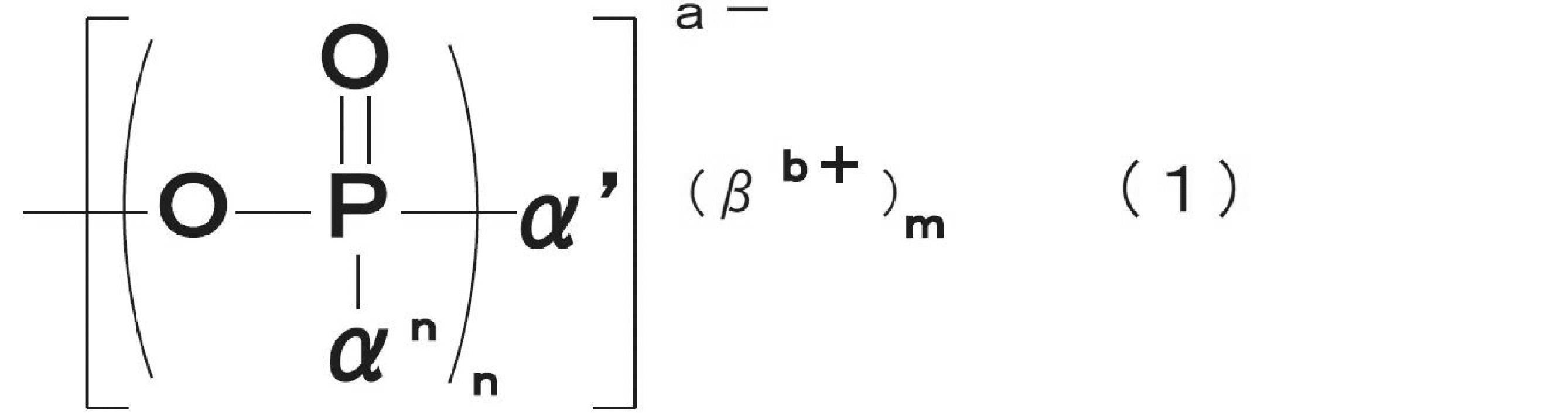
式(1)中、a、bおよびnは自然数である(ただし、a=b×mである)。α1,α2,・・・,αnおよびα’のうちa個がO-であり、残りはR,ORのいずれかである。なお、各αnおよびα’の全てがO-であっても構わない。Rは、各々、水素原子、飽和-直鎖状炭化水素基、飽和-分岐鎖状炭化水素基、飽和-環状炭化水素基、不飽和-直鎖状炭化水素基、不飽和-分岐鎖状炭化水素基、不飽和-環状炭化水素基、芳香族基、またはこれらの誘導基である。また、nは1であることが好ましい。
飽和-直鎖状炭化水素基としては、メチル基、エチル基、n-プロピル基、又はn-ブチル基等が挙げられるが、特に限定されない。飽和-分岐鎖状炭化水素基としては、i-プロピル基、又はt-ブチル基等が挙げられるが、特に限定されない。飽和-環状炭化水素基としては、シクロペンチル基、又はシクロヘキシル基等が挙げられるが、特に限定されない。不飽和-直鎖状炭化水素基としては、ビニル基、又はアリル基等が挙げられるが、特に限定されない。不飽和-分岐鎖状炭化水素基としては、i-プロペニル基、又は3-ブテニル基等が挙げられるが、特に限定されない。不飽和-環状炭化水素基としては、シクロペンテニル基、シクロヘキセニル基等が挙げられるが、特に限定されない。芳香族基としては、フェニル基、又はナフチル基等が挙げられるが、特に限定されない。
また、Rにおける誘導基としては、上記各種炭化水素基の主鎖又は側鎖に対し、カルボキシ基、ヒドロキシ基、又はアミノ基などの官能基のうち、少なくとも1種類が付加又は置換した状態の官能基が挙げられるが、特に限定されない。また、Rの主鎖を構成する炭素原子数は特に限定されないが、20以下であることが好ましく、10以下であることがより好ましい。Rの主鎖を構成する炭素原子数を上記範囲とすることにより、リンオキソ酸基の分子量を適切な範囲とすることができ、繊維原料への浸透を容易にし、微細セルロース繊維の収率を高めることもできる。
βb+は有機物又は無機物からなる1価以上の陽イオンである。有機物からなる1価以上の陽イオンとしては、脂肪族アンモニウム、又は芳香族アンモニウムが挙げられ、無機物からなる1価以上の陽イオンとしては、ナトリウム、カリウム、若しくはリチウム等のアルカリ金属のイオンや、カルシウム、若しくはマグネシウム等の2価金属の陽イオン、又は水素イオン等が挙げられるが、特に限定されない。これらは1種又は2種類以上を組み合わせて適用することもできる。有機物又は無機物からなる1価以上の陽イオンとしては、βを含む繊維原料を加熱した際に黄変しにくく、また工業的に利用し易いナトリウム、又はカリウムのイオンが好ましいが、特に限定されない。なお、βb+は有機オニウムイオンであってもよく、この場合、有機アンモニウムイオンであることが特に好ましい。
繊維状セルロースに対するイオン性置換基の導入量は、たとえば繊維状セルロース1g(質量)あたり0.10mmol/g以上であることが好ましく、0.20mmol/g以上であることがより好ましく、0.50mmol/g以上であることがさらに好ましく、1.00mmol/g以上であることがとくに好ましい。また、繊維状セルロースに対するイオン性置換基の導入量は、たとえば繊維状セルロース1g(質量)あたり5.20mmol/g以下であることが好ましく、3.65mmol/g以下であることがより好ましく、3.50mmol/g以下であることがさらに好ましく、3.00mmol/g以下であることが一層好ましい。イオン性置換基の導入量を上記範囲内とすることにより、繊維原料の微細化を容易とすることができ、繊維状セルロースの安定性を高めることが可能となる。ここで、単位mmol/gにおける分母は、イオン性置換基の対イオンが水素イオン(H+)であるときの繊維状セルロースの質量を示す。
繊維状セルロースに対するイオン性置換基の導入量は、たとえば中和滴定法により測定することができる。中和滴定法による測定では、得られた繊維状セルロースを含有するスラリーに、水酸化ナトリウム水溶液などのアルカリを加えながらpHの変化を求めることにより、導入量を測定する。
図4は、イオン性置換基としてリンオキソ酸基を有する繊維状セルロース含有スラリーに対するNaOH滴下量とpHの関係を示すグラフである。繊維状セルロースに対するリンオキソ酸基の導入量は、たとえば次のように測定される。
まず、繊維状セルロースを含有するスラリーを強酸性イオン交換樹脂で処理する。なお、必要に応じて、強酸性イオン交換樹脂による処理の前に、後述の解繊処理工程と同様の解繊処理を測定対象に対して実施してもよい。
次いで、水酸化ナトリウム水溶液を加えながらpHの変化を観察し、図4の上側部に示すような滴定曲線を得る。図4の上側部に示した滴定曲線では、アルカリを加えた量に対して測定したpHをプロットしており、図4の下側部に示した滴定曲線では、アルカリを加えた量に対するpHの増分(微分値)(1/mmol)をプロットしている。この中和滴定では、アルカリを加えた量に対して測定したpHをプロットした曲線において、増分(pHのアルカリ滴下量に対する微分値)が極大となる点が二つ確認される。これらのうち、アルカリを加えはじめて先に得られる増分の極大点を第1終点と呼び、次に得られる増分の極大点を第2終点と呼ぶ。滴定開始から第1終点までに必要としたアルカリ量が、滴定に使用したスラリー中に含まれる繊維状セルロースの第1解離酸量と等しくなり、第1終点から第2終点までに必要としたアルカリ量が滴定に使用したスラリー中に含まれる繊維状セルロースの第2解離酸量と等しくなり、滴定開始から第2終点までに必要としたアルカリ量が滴定に使用したスラリー中に含まれる繊維状セルロースの総解離酸量と等しくなる。そして、滴定開始から第1終点までに必要としたアルカリ量を滴定対象スラリー中の固形分(g)で除して得られる値が、リンオキソ酸基導入量(mmol/g)となる。なお、単にリンオキソ酸基導入量(またはリンオキソ酸基量)と言った場合は、第1解離酸量のことを表す。
なお、図4において、滴定開始から第1終点までの領域を第1領域と呼び、第1終点から第2終点までの領域を第2領域と呼ぶ。例えば、リンオキソ酸基がリン酸基の場合であって、このリン酸基が縮合を起こす場合、見かけ上、リンオキソ酸基における弱酸性基量(第2解離酸量)が低下し、第1領域に必要としたアルカリ量と比較して第2領域に必要としたアルカリ量が少なくなる。一方、リンオキソ酸基における強酸性基量(第1解離酸量)は、縮合の有無に関わらずリン原子の量と一致する。また、リンオキソ酸基が亜リン酸基の場合は、リンオキソ酸基に弱酸性基が存在しなくなるため、第2領域に必要としたアルカリ量が少なくなるか、第2領域に必要としたアルカリ量はゼロとなる場合もある。この場合、滴定曲線において、pHの増分が極大となる点は一つとなる。
まず、繊維状セルロースを含有するスラリーを強酸性イオン交換樹脂で処理する。なお、必要に応じて、強酸性イオン交換樹脂による処理の前に、後述の解繊処理工程と同様の解繊処理を測定対象に対して実施してもよい。
次いで、水酸化ナトリウム水溶液を加えながらpHの変化を観察し、図4の上側部に示すような滴定曲線を得る。図4の上側部に示した滴定曲線では、アルカリを加えた量に対して測定したpHをプロットしており、図4の下側部に示した滴定曲線では、アルカリを加えた量に対するpHの増分(微分値)(1/mmol)をプロットしている。この中和滴定では、アルカリを加えた量に対して測定したpHをプロットした曲線において、増分(pHのアルカリ滴下量に対する微分値)が極大となる点が二つ確認される。これらのうち、アルカリを加えはじめて先に得られる増分の極大点を第1終点と呼び、次に得られる増分の極大点を第2終点と呼ぶ。滴定開始から第1終点までに必要としたアルカリ量が、滴定に使用したスラリー中に含まれる繊維状セルロースの第1解離酸量と等しくなり、第1終点から第2終点までに必要としたアルカリ量が滴定に使用したスラリー中に含まれる繊維状セルロースの第2解離酸量と等しくなり、滴定開始から第2終点までに必要としたアルカリ量が滴定に使用したスラリー中に含まれる繊維状セルロースの総解離酸量と等しくなる。そして、滴定開始から第1終点までに必要としたアルカリ量を滴定対象スラリー中の固形分(g)で除して得られる値が、リンオキソ酸基導入量(mmol/g)となる。なお、単にリンオキソ酸基導入量(またはリンオキソ酸基量)と言った場合は、第1解離酸量のことを表す。
なお、図4において、滴定開始から第1終点までの領域を第1領域と呼び、第1終点から第2終点までの領域を第2領域と呼ぶ。例えば、リンオキソ酸基がリン酸基の場合であって、このリン酸基が縮合を起こす場合、見かけ上、リンオキソ酸基における弱酸性基量(第2解離酸量)が低下し、第1領域に必要としたアルカリ量と比較して第2領域に必要としたアルカリ量が少なくなる。一方、リンオキソ酸基における強酸性基量(第1解離酸量)は、縮合の有無に関わらずリン原子の量と一致する。また、リンオキソ酸基が亜リン酸基の場合は、リンオキソ酸基に弱酸性基が存在しなくなるため、第2領域に必要としたアルカリ量が少なくなるか、第2領域に必要としたアルカリ量はゼロとなる場合もある。この場合、滴定曲線において、pHの増分が極大となる点は一つとなる。
なお、上述のリンオキソ酸基導入量(mmol/g)は、分母が酸型の繊維状セルロースの質量を示すことから、酸型の繊維状セルロースが有するリンオキソ酸基量(以降、リンオキソ酸基量(酸型)と呼ぶ)を示している。一方で、リンオキソ酸基の対イオンが電荷当量となるように任意の陽イオンCに置換されている場合は、分母を当該陽イオンCが対イオンであるときの繊維状セルロースの質量に変換することで、陽イオンCが対イオンである繊維状セルロースが有するリンオキソ酸基量(以降、リンオキソ酸基量(C型))を求めることができる。
すなわち、下記計算式によって算出する。
リンオキソ酸基量(C型)=リンオキソ酸基量(酸型)/{1+(W-1)×A/1000}
A[mmol/g]:繊維状セルロースが有するリンオキソ酸基由来の総アニオン量(リンオキソ酸基の総解離酸量)
W:陽イオンCの1価あたりの式量(たとえば、Naは23、Alは9)
すなわち、下記計算式によって算出する。
リンオキソ酸基量(C型)=リンオキソ酸基量(酸型)/{1+(W-1)×A/1000}
A[mmol/g]:繊維状セルロースが有するリンオキソ酸基由来の総アニオン量(リンオキソ酸基の総解離酸量)
W:陽イオンCの1価あたりの式量(たとえば、Naは23、Alは9)
図5は、イオン性置換基としてカルボキシ基を有する繊維状セルロースを含有する分散液に対するNaOH滴下量とpHの関係を示すグラフである。繊維状セルロースに対するカルボキシ基の導入量は、たとえば次のように測定される。
まず、繊維状セルロースを含有する分散液を強酸性イオン交換樹脂で処理する。なお、必要に応じて、強酸性イオン交換樹脂による処理の前に、後述の解繊処理工程と同様の解繊処理を測定対象に対して実施してもよい。
次いで、水酸化ナトリウム水溶液を加えながらpHの変化を観察し、図5の上側部に示すような滴定曲線を得る。図5の上側部に示した滴定曲線では、アルカリを加えた量に対して測定したpHをプロットしており、図5の下側部に示した滴定曲線では、アルカリを加えた量に対するpHの増分(微分値)(1/mmol)をプロットしている。この中和滴定では、アルカリを加えた量に対して測定したpHをプロットした曲線において、増分(pHのアルカリ滴下量に対する微分値)が極大となる点が一つ確認され、この極大点を第1終点と呼ぶ。ここで、図5における滴定開始から第1終点までの領域を第1領域と呼ぶ。第1領域で必要としたアルカリ量が、滴定に使用した分散液中のカルボキシ基量と等しくなる。そして、滴定曲線の第1領域で必要としたアルカリ量(mmol)を、滴定対象の繊維状セルロースを含有する分散液中の固形分(g)で除すことで、カルボキシ基の導入量(mmol/g)を算出する。
まず、繊維状セルロースを含有する分散液を強酸性イオン交換樹脂で処理する。なお、必要に応じて、強酸性イオン交換樹脂による処理の前に、後述の解繊処理工程と同様の解繊処理を測定対象に対して実施してもよい。
次いで、水酸化ナトリウム水溶液を加えながらpHの変化を観察し、図5の上側部に示すような滴定曲線を得る。図5の上側部に示した滴定曲線では、アルカリを加えた量に対して測定したpHをプロットしており、図5の下側部に示した滴定曲線では、アルカリを加えた量に対するpHの増分(微分値)(1/mmol)をプロットしている。この中和滴定では、アルカリを加えた量に対して測定したpHをプロットした曲線において、増分(pHのアルカリ滴下量に対する微分値)が極大となる点が一つ確認され、この極大点を第1終点と呼ぶ。ここで、図5における滴定開始から第1終点までの領域を第1領域と呼ぶ。第1領域で必要としたアルカリ量が、滴定に使用した分散液中のカルボキシ基量と等しくなる。そして、滴定曲線の第1領域で必要としたアルカリ量(mmol)を、滴定対象の繊維状セルロースを含有する分散液中の固形分(g)で除すことで、カルボキシ基の導入量(mmol/g)を算出する。
なお、上述のカルボキシ基導入量(mmol/g)は、分母が酸型の繊維状セルロースの質量であることから、酸型の繊維状セルロースが有するカルボキシ基量(以降、カルボキシ基量(酸型)と呼ぶ)を示している。一方で、カルボキシ基の対イオンが電荷当量となるように任意の陽イオンCに置換されている場合は、分母を当該陽イオンCが対イオンであるときの繊維状セルロースの質量に変換することで、陽イオンCが対イオンである繊維状セルロースが有するカルボキシ基量(以降、カルボキシ基量(C型))を求めることができる。すなわち、下記計算式によって算出する。
カルボキシ基量(C型)=カルボキシ基量(酸型)/{1+(W-1)×(カルボキシ基量(酸型))/1000}
W:陽イオンCの1価あたりの式量(たとえば、Naは23、Alは9)
カルボキシ基量(C型)=カルボキシ基量(酸型)/{1+(W-1)×(カルボキシ基量(酸型))/1000}
W:陽イオンCの1価あたりの式量(たとえば、Naは23、Alは9)
滴定法によるイオン性置換基量の測定においては、水酸化ナトリウム水溶液1滴の滴下量が多すぎる場合や、滴定間隔が短すぎる場合、本来より低いイオン性置換基量となるなど正確な値が得られないことがある。適切な滴下量、滴定間隔としては、例えば、0.1N水酸化ナトリウム水溶液を5~30秒に10~50μLずつ滴定するなどが望ましい。また、繊維状セルロース含有スラリーに溶解した二酸化炭素の影響を排除するため、例えば、滴定開始の15分前から滴定終了まで、窒素ガスなどの不活性ガスをスラリーに吹き込みながら測定するなどが望ましい。
<微細繊維状セルロースの製造工程>
<繊維原料>
微細繊維状セルロースは、セルロースを含む繊維原料から製造される。セルロースを含む繊維原料としては、特に限定されないが、入手しやすく安価である点からパルプを用いることが好ましい。パルプとしては、たとえば木材パルプ、非木材パルプ、および脱墨パルプが挙げられる。木材パルプとしては、特に限定されないが、たとえば広葉樹クラフトパルプ(LBKP)、針葉樹クラフトパルプ(NBKP)、サルファイトパルプ(SP)、溶解パルプ(DP)、ソーダパルプ(AP)、未晒しクラフトパルプ(UKP)および酸素漂白クラフトパルプ(OKP)等の化学パルプ、セミケミカルパルプ(SCP)およびケミグラウンドウッドパルプ(CGP)等の半化学パルプ、砕木パルプ(GP)およびサーモメカニカルパルプ(TMP、BCTMP)等の機械パルプ等が挙げられる。非木材パルプとしては、特に限定されないが、たとえばコットンリンターおよびコットンリント等の綿系パルプ、麻、麦わらおよびバガス等の非木材系パルプが挙げられる。脱墨パルプとしては、特に限定されないが、たとえば古紙を原料とする脱墨パルプが挙げられる。本実施態様のパルプは上記の1種を単独で用いてもよいし、2種以上混合して用いてもよい。上記パルプの中でも、入手のしやすさという観点からは、たとえば木材パルプおよび脱墨パルプが好ましい。また、木材パルプの中でも、セルロース比率が大きく解繊処理時の微細繊維状セルロースの収率が高い観点や、パルプ中のセルロースの分解が小さく軸比の大きい長繊維の微細繊維状セルロースが得られる観点から、たとえば化学パルプがより好ましく、クラフトパルプ、サルファイトパルプがさらに好ましい。なお、軸比の大きい長繊維の微細繊維状セルロースを用いると粘度が高くなる傾向がある。
<繊維原料>
微細繊維状セルロースは、セルロースを含む繊維原料から製造される。セルロースを含む繊維原料としては、特に限定されないが、入手しやすく安価である点からパルプを用いることが好ましい。パルプとしては、たとえば木材パルプ、非木材パルプ、および脱墨パルプが挙げられる。木材パルプとしては、特に限定されないが、たとえば広葉樹クラフトパルプ(LBKP)、針葉樹クラフトパルプ(NBKP)、サルファイトパルプ(SP)、溶解パルプ(DP)、ソーダパルプ(AP)、未晒しクラフトパルプ(UKP)および酸素漂白クラフトパルプ(OKP)等の化学パルプ、セミケミカルパルプ(SCP)およびケミグラウンドウッドパルプ(CGP)等の半化学パルプ、砕木パルプ(GP)およびサーモメカニカルパルプ(TMP、BCTMP)等の機械パルプ等が挙げられる。非木材パルプとしては、特に限定されないが、たとえばコットンリンターおよびコットンリント等の綿系パルプ、麻、麦わらおよびバガス等の非木材系パルプが挙げられる。脱墨パルプとしては、特に限定されないが、たとえば古紙を原料とする脱墨パルプが挙げられる。本実施態様のパルプは上記の1種を単独で用いてもよいし、2種以上混合して用いてもよい。上記パルプの中でも、入手のしやすさという観点からは、たとえば木材パルプおよび脱墨パルプが好ましい。また、木材パルプの中でも、セルロース比率が大きく解繊処理時の微細繊維状セルロースの収率が高い観点や、パルプ中のセルロースの分解が小さく軸比の大きい長繊維の微細繊維状セルロースが得られる観点から、たとえば化学パルプがより好ましく、クラフトパルプ、サルファイトパルプがさらに好ましい。なお、軸比の大きい長繊維の微細繊維状セルロースを用いると粘度が高くなる傾向がある。
セルロースを含む繊維原料としては、たとえばホヤ類に含まれるセルロースや、酢酸菌が生成するバクテリアセルロースを利用することもできる。また、セルロースを含む繊維原料に代えて、キチン、キトサンなどの直鎖型の含窒素多糖高分子が形成する繊維を用いることもできる。
<リンオキソ酸基導入工程>
微細繊維状セルロースの製造工程は、イオン性置換基導入工程を含むことが好ましく、イオン性置換基導入工程としては、例えば、リンオキソ酸基導入工程が挙げられる。リンオキソ酸基導入工程は、セルロースを含む繊維原料が有する水酸基と反応することで、リンオキソ酸基を導入できる化合物から選択される少なくとも1種の化合物(以下、「化合物A」ともいう)を、セルロースを含む繊維原料に作用させる工程である。この工程により、リンオキソ酸基導入繊維が得られることとなる。
微細繊維状セルロースの製造工程は、イオン性置換基導入工程を含むことが好ましく、イオン性置換基導入工程としては、例えば、リンオキソ酸基導入工程が挙げられる。リンオキソ酸基導入工程は、セルロースを含む繊維原料が有する水酸基と反応することで、リンオキソ酸基を導入できる化合物から選択される少なくとも1種の化合物(以下、「化合物A」ともいう)を、セルロースを含む繊維原料に作用させる工程である。この工程により、リンオキソ酸基導入繊維が得られることとなる。
本実施形態に係るリンオキソ酸基導入工程では、セルロースを含む繊維原料と化合物Aの反応を、尿素及びその誘導体から選択される少なくとも1種(以下、「化合物B」ともいう)の存在下で行ってもよい。一方で、化合物Bが存在しない状態において、セルロースを含む繊維原料と化合物Aの反応を行ってもよい。
化合物Aを化合物Bとの共存下で繊維原料に作用させる方法の一例としては、乾燥状態、湿潤状態またはスラリー状の繊維原料に対して、化合物Aと化合物Bを混合する方法が挙げられる。これらのうち、反応の均一性が高いことから、乾燥状態または湿潤状態の繊維原料を用いることが好ましく、特に乾燥状態の繊維原料を用いることが好ましい。繊維原料の形態は、特に限定されないが、たとえば綿状や薄いシート状であることが好ましい。化合物Aおよび化合物Bは、それぞれ粉末状または溶媒に溶解させた溶液状または融点以上まで加熱して溶融させた状態で繊維原料に添加する方法が挙げられる。これらのうち、反応の均一性が高いことから、溶媒に溶解させた溶液状、特に水溶液の状態で添加することが好ましい。また、化合物Aと化合物Bは繊維原料に対して同時に添加してもよく、別々に添加してもよく、混合物として添加してもよい。化合物Aと化合物Bの添加方法としては、特に限定されないが、化合物Aと化合物Bが溶液状の場合は、繊維原料を溶液内に浸漬し吸液させたのちに取り出してもよいし、繊維原料に溶液を滴下してもよい。また、必要量の化合物Aと化合物Bを繊維原料に添加してもよいし、過剰量の化合物Aと化合物Bをそれぞれ繊維原料に添加した後に、圧搾や濾過によって余剰の化合物Aと化合物Bを除去してもよい。
本実施態様で使用する化合物Aとしては、リン原子を有し、セルロースとエステル結合を形成可能な化合物であればよく、リン酸もしくはその塩、亜リン酸もしくはその塩、脱水縮合リン酸もしくはその塩、無水リン酸(五酸化二リン)などが挙げられるが特に限定されない。リン酸としては、種々の純度のものを使用することができ、たとえば100%リン酸(正リン酸)や85%リン酸を使用することができる。亜リン酸としては、99%亜リン酸(ホスホン酸)が挙げられる。脱水縮合リン酸は、リン酸が脱水反応により2分子以上縮合したものであり、例えばピロリン酸、ポリリン酸等を挙げることができる。リン酸塩、亜リン酸塩、脱水縮合リン酸塩としては、リン酸、亜リン酸または脱水縮合リン酸のリチウム塩、ナトリウム塩、カリウム塩、アンモニウム塩などが挙げられ、これらは種々の中和度とすることができる。これらのうち、リン酸基の導入効率が高く、後述する解繊工程で解繊効率がより向上しやすく、低コストであり、かつ工業的に適用しやすい観点から、リン酸、リン酸のナトリウム塩、リン酸のカリウム塩、リン酸のアンモニウム塩または亜リン酸、亜リン酸のナトリウム塩、亜リン酸のカリウム塩、亜リン酸のアンモニウム塩が好ましく、リン酸、リン酸二水素ナトリウム、リン酸水素二ナトリウム、リン酸二水素アンモニウム、または亜リン酸、亜リン酸ナトリウムがより好ましい。
繊維原料に対する化合物Aの添加量は、特に限定されないが、たとえば化合物Aの添加量をリン原子量に換算した場合において、繊維原料(絶乾質量)に対するリン原子の添加量が0.5質量%以上100質量%以下となることが好ましく、1質量%以上50質量%以下となることがより好ましく、2質量%以上30質量%以下となることがさらに好ましい。繊維原料に対するリン原子の添加量を上記範囲内とすることにより、微細繊維状セルロースの収率をより向上させることができる。一方で、繊維原料に対するリン原子の添加量を上記上限値以下とすることにより、収率向上の効果とコストのバランスをとることができる。
本実施態様で使用する化合物Bは、上述のとおり尿素及びその誘導体から選択される少なくとも1種である。化合物Bとしては、たとえば尿素、ビウレット、1-フェニル尿素、1-ベンジル尿素、1-メチル尿素、および1-エチル尿素などが挙げられる。
反応の均一性を向上させる観点から、化合物Bは水溶液として用いることが好ましい。また、反応の均一性をさらに向上させる観点からは、化合物Aと化合物Bの両方が溶解した水溶液を用いることが好ましい。
反応の均一性を向上させる観点から、化合物Bは水溶液として用いることが好ましい。また、反応の均一性をさらに向上させる観点からは、化合物Aと化合物Bの両方が溶解した水溶液を用いることが好ましい。
繊維原料(絶乾質量)に対する化合物Bの添加量は、特に限定されないが、たとえば1質量%以上500質量%以下であることが好ましく、10質量%以上400質量%以下であることがより好ましく、100質量%以上350質量%以下であることがさらに好ましい。
セルロースを含む繊維原料と化合物Aの反応においては、化合物Bの他に、たとえばアミド類またはアミン類を反応系に含んでもよい。アミド類としては、たとえばホルムアミド、ジメチルホルムアミド、アセトアミド、ジメチルアセトアミドなどが挙げられる。アミン類としては、たとえばメチルアミン、エチルアミン、トリメチルアミン、トリエチルアミン、モノエタノールアミン、ジエタノールアミン、トリエタノールアミン、ピリジン、エチレンジアミン、ヘキサメチレンジアミンなどが挙げられる。これらの中でも、特にトリエチルアミンは良好な反応触媒として働くことが知られている。
リンオキソ酸基導入工程においては、繊維原料に化合物A等を添加又は混合した後、当該繊維原料に対して加熱処理を施すことが好ましい。加熱処理温度としては、繊維の熱分解や加水分解反応を抑えながら、リンオキソ酸基を効率的に導入できる温度を選択することが好ましい。加熱処理温度は、たとえば50℃以上300℃以下であることが好ましく、100℃以上250℃以下であることがより好ましく、130℃以上200℃以下であることがさらに好ましい。また、加熱処理には、種々の熱媒体を有する機器を利用することができ、たとえば撹拌乾燥装置、回転乾燥装置、円盤乾燥装置、ロール型加熱装置、プレート型加熱装置、流動層乾燥装置、バンド型乾燥装置、ろ過乾燥装置、振動流動乾燥装置、気流乾燥装置、減圧乾燥装置、赤外線加熱装置、遠赤外線加熱装置、マイクロ波加熱装置、高周波乾燥装置を用いることができる。
本実施形態に係る加熱処理においては、たとえば薄いシート状の繊維原料に化合物Aを含浸等の方法により添加した後、加熱する方法や、ニーダー等で繊維原料と化合物Aを混練又は撹拌しながら加熱する方法を採用することができる。これにより、繊維原料における化合物Aの濃度ムラを抑制して、繊維原料に含まれるセルロース繊維表面へより均一にリンオキソ酸基を導入することが可能となる。これは、乾燥に伴い水分子が繊維原料表面に移動する際、溶存する化合物Aが表面張力によって水分子に引き付けられ、同様に繊維原料表面に移動してしまう(すなわち、化合物Aの濃度ムラを生じてしまう)ことを抑制できることに起因するものと考えられる。
また、加熱処理に用いる加熱装置は、たとえばスラリーが保持する水分、及び化合物Aと繊維原料中のセルロース等が含む水酸基等との脱水縮合(リン酸エステル化)反応に伴って生じる水分、を常に装置系外に排出できる装置であることが好ましい。このような加熱装置としては、例えば送風方式のオーブン等が挙げられる。装置系内の水分を常に排出することにより、リン酸エステル化の逆反応であるリン酸エステル結合の加水分解反応を抑制できることに加えて、繊維中の糖鎖の酸加水分解を抑制することもできる。このため、軸比の高い微細繊維状セルロースを得ることが可能となる。
加熱処理の時間は、たとえば繊維原料から実質的に水分が除かれてから1秒以上300分以下であることが好ましく、1秒以上1000秒以下であることがより好ましく、10秒以上800秒以下であることがさらに好ましい。本実施形態では、加熱温度と加熱時間を適切な範囲とすることにより、リンオキソ酸基の導入量を好ましい範囲内とすることができる。
リンオキソ酸基導入工程は、少なくとも1回行えば良いが、2回以上繰り返して行うこともできる。2回以上のリンオキソ酸基導入工程を行うことにより、繊維原料に対して多くのリンオキソ酸基を導入することができる。本実施形態においては、好ましい態様の一例として、リンオキソ酸基導入工程を2回行う場合が挙げられる。
繊維原料に対するリンオキソ酸基の導入量は、たとえば微細繊維状セルロース1g(質量)あたり0.10mmol/g以上であることが好ましく、0.20mmol/g以上であることがより好ましく、0.50mmol/g以上であることがさらに好ましく、1.00mmol/g以上であることがとくに好ましい。また、繊維原料に対するリンオキソ酸基の導入量は、たとえば微細繊維状セルロース1g(質量)あたり5.20mmol/g以下であることが好ましく、3.65mmol/g以下であることがより好ましく、3.00mmol/g以下であることがさらに好ましい。リンオキソ酸基の導入量を上記範囲内とすることにより、繊維原料の微細化を容易にし、微細繊維状セルロースの安定性を高めることができる。
<カルボキシ基導入工程>
微細繊維状セルロースの製造工程は、イオン性置換基導入工程として、例えば、カルボキシ基導入工程を含んでもよい。カルボキシ基導入工程は、セルロースを含む繊維原料に対し、オゾン酸化やフェントン法による酸化、TEMPO酸化処理などの酸化処理やカルボン酸由来の基を有する化合物もしくはその誘導体、またはカルボン酸由来の基を有する化合物の酸無水物もしくはその誘導体によって処理することにより行われる。
微細繊維状セルロースの製造工程は、イオン性置換基導入工程として、例えば、カルボキシ基導入工程を含んでもよい。カルボキシ基導入工程は、セルロースを含む繊維原料に対し、オゾン酸化やフェントン法による酸化、TEMPO酸化処理などの酸化処理やカルボン酸由来の基を有する化合物もしくはその誘導体、またはカルボン酸由来の基を有する化合物の酸無水物もしくはその誘導体によって処理することにより行われる。
カルボン酸由来の基を有する化合物としては、特に限定されないが、たとえばマレイン酸、コハク酸、フタル酸、フマル酸、グルタル酸、アジピン酸、イタコン酸等のジカルボン酸化合物やクエン酸、アコニット酸等のトリカルボン酸化合物が挙げられる。また、カルボン酸由来の基を有する化合物の誘導体としては、特に限定されないが、たとえばカルボキシ基を有する化合物の酸無水物のイミド化物、カルボキシ基を有する化合物の酸無水物の誘導体が挙げられる。カルボキシ基を有する化合物の酸無水物のイミド化物としては、とくに限定されないが、たとえばマレイミド、コハク酸イミド、フタル酸イミド等のジカルボン酸化合物のイミド化物が挙げられる。
カルボン酸由来の基を有する化合物の酸無水物としては、特に限定されないが、たとえば無水マレイン酸、無水コハク酸、無水フタル酸、無水グルタル酸、無水アジピン酸、無水イタコン酸等のジカルボン酸化合物の酸無水物が挙げられる。また、カルボン酸由来の基を有する化合物の酸無水物の誘導体としては、特に限定されないが、たとえばジメチルマレイン酸無水物、ジエチルマレイン酸無水物、ジフェニルマレイン酸無水物等のカルボキシ基を有する化合物の酸無水物の少なくとも一部の水素原子が、アルキル基、フェニル基等の置換基により置換されたものが挙げられる。
カルボキシ基導入工程において、TEMPO酸化処理を行う場合には、たとえばその処理をpHが6以上8以下の条件で行うことが好ましい。このような処理は、中性TEMPO酸化処理ともいう。中性TEMPO酸化処理は、たとえばリン酸ナトリウム緩衝液(pH=6.8)に、繊維原料としてパルプと、触媒としてTEMPO(2,2,6,6-テトラメチルピペリジン-1-オキシル)等のニトロキシラジカル、犠牲試薬として次亜塩素酸ナトリウムを添加することで行うことができる。さらに亜塩素酸ナトリウムを共存させることによって、酸化の過程で発生するアルデヒドを、効率的にカルボキシ基まで酸化することができる。また、TEMPO酸化処理は、その処理をpHが10以上11以下の条件で行ってもよい。このような処理は、アルカリTEMPO酸化処理ともいう。アルカリTEMPO酸化処理は、たとえば繊維原料としてのパルプに対し、触媒としてTEMPO等のニトロキシラジカルと、共触媒として臭化ナトリウムと、酸化剤として次亜塩素酸ナトリウムを添加することにより行うことができる。
繊維原料に対するカルボキシ基の導入量は、置換基の種類によっても変わるが、たとえばTEMPO酸化によりカルボキシ基を導入する場合、微細繊維状セルロース1g(質量)あたり0.10mmol/g以上であることが好ましく、0.20mmol/g以上であることがより好ましく、0.50mmol/g以上であることがさらに好ましく、0.90mmol/g以上であることがとくに好ましい。また、2.5mmol/g以下であることが好ましく、2.20mmol/g以下であることがより好ましく、2.00mmol/g以下であることがさらに好ましい。その他、置換基がカルボキシメチル基である場合、微細繊維状セルロース1g(質量)あたり5.8mmol/g以下であってもよい。
<洗浄工程>
本実施形態における微細繊維状セルロースの製造方法においては、必要に応じてイオン性置換基導入繊維に対して洗浄工程を行うことができる。洗浄工程は、たとえば水や有機溶媒によりイオン性置換基導入繊維を洗浄することにより行われる。また、洗浄工程は後述する各工程の後に行われてもよく、各洗浄工程において実施される洗浄回数は、特に限定されない。
本実施形態における微細繊維状セルロースの製造方法においては、必要に応じてイオン性置換基導入繊維に対して洗浄工程を行うことができる。洗浄工程は、たとえば水や有機溶媒によりイオン性置換基導入繊維を洗浄することにより行われる。また、洗浄工程は後述する各工程の後に行われてもよく、各洗浄工程において実施される洗浄回数は、特に限定されない。
<アルカリ処理工程>
微細繊維状セルロースを製造する場合、イオン性置換基導入工程と、後述する解繊処理工程との間に、繊維原料に対してアルカリ処理を行ってもよい。アルカリ処理の方法としては、特に限定されないが、例えばアルカリ溶液中に、イオン性置換基導入繊維を浸漬する方法が挙げられる。
微細繊維状セルロースを製造する場合、イオン性置換基導入工程と、後述する解繊処理工程との間に、繊維原料に対してアルカリ処理を行ってもよい。アルカリ処理の方法としては、特に限定されないが、例えばアルカリ溶液中に、イオン性置換基導入繊維を浸漬する方法が挙げられる。
アルカリ溶液に含まれるアルカリ化合物は、特に限定されず、無機アルカリ化合物であってもよいし、有機アルカリ化合物であってもよい。本実施形態においては、汎用性が高いことから、たとえば水酸化ナトリウムまたは水酸化カリウムをアルカリ化合物として用いることが好ましい。また、アルカリ溶液に含まれる溶媒は、水または有機溶媒のいずれであってもよい。中でも、アルカリ溶液に含まれる溶媒は、水、またはアルコールに例示される極性有機溶媒などを含む極性溶媒であることが好ましく、少なくとも水を含む水系溶媒であることがより好ましい。アルカリ溶液としては、汎用性が高いことから、たとえば水酸化ナトリウム水溶液、または水酸化カリウム水溶液が好ましい。
アルカリ処理工程におけるアルカリ溶液の温度は、特に限定されないが、たとえば5℃以上80℃以下であることが好ましく、10℃以上60℃以下であることがより好ましい。アルカリ処理工程におけるイオン性置換基導入繊維のアルカリ溶液への浸漬時間は、特に限定されないが、たとえば5分以上30分以下であることが好ましく、10分以上20分以下であることがより好ましい。アルカリ処理におけるアルカリ溶液の使用量は、特に限定されないが、たとえばイオン性置換基導入繊維の絶対乾燥質量に対して100質量%以上100000質量%以下であることが好ましく、1000質量%以上10000質量%以下であることがより好ましい。
アルカリ処理工程におけるアルカリ溶液の使用量を減らすために、イオン性置換基導入工程の後であってアルカリ処理工程の前に、イオン性置換基導入繊維を水や有機溶媒により洗浄してもよい。アルカリ処理工程の後であって解繊処理工程の前には、取り扱い性を向上させる観点から、アルカリ処理を行ったイオン性置換基導入繊維を水や有機溶媒により洗浄することが好ましい。
<酸処理工程>
微細繊維状セルロースを製造する場合、イオン性置換基を導入する工程と、後述する解繊処理工程の間に、繊維原料に対して酸処理を行ってもよい。例えば、イオン性置換基導入工程、酸処理、アルカリ処理及び解繊処理をこの順で行ってもよい。
微細繊維状セルロースを製造する場合、イオン性置換基を導入する工程と、後述する解繊処理工程の間に、繊維原料に対して酸処理を行ってもよい。例えば、イオン性置換基導入工程、酸処理、アルカリ処理及び解繊処理をこの順で行ってもよい。
酸処理の方法としては、特に限定されないが、たとえば酸を含有する酸性液中に繊維原料を浸漬する方法が挙げられる。使用する酸性液の濃度は、特に限定されないが、たとえば10質量%以下であることが好ましく、5質量%以下であることがより好ましい。また、使用する酸性液のpHは、特に限定されないが、たとえば0以上4以下であることが好ましく、1以上3以下であることがより好ましい。酸性液に含まれる酸としては、たとえば無機酸、スルホン酸、カルボン酸等を用いることができる。無機酸としては、たとえば硫酸、硝酸、塩酸、臭化水素酸、ヨウ化水素酸、次亜塩素酸、亜塩素酸、塩素酸、過塩素酸、リン酸、ホウ酸等が挙げられる。スルホン酸としては、たとえばメタンスルホン酸、エタンスルホン酸、ベンゼンスルホン酸、p-トルエンスルホン酸、トリフルオロメタンスルホン酸等が挙げられる。カルボン酸としては、たとえばギ酸、酢酸、クエン酸、グルコン酸、乳酸、シュウ酸、酒石酸等が挙げられる。これらの中でも、塩酸または硫酸を用いることが特に好ましい。
酸処理における酸溶液の温度は、特に限定されないが、たとえば5℃以上100℃以下が好ましく、20℃以上90℃以下がより好ましい。酸処理における酸溶液への浸漬時間は、特に限定されないが、たとえば5分以上120分以下が好ましく、10分以上60分以下がより好ましい。酸処理における酸溶液の使用量は、特に限定されないが、たとえば繊維原料の絶対乾燥質量に対して100質量%以上100000質量%以下であることが好ましく、1000質量%以上10000質量%以下であることがより好ましい。
<解繊処理>
イオン性置換基導入繊維を解繊処理工程で解繊処理することにより、微細繊維状セルロースが得られる。解繊処理工程においては、たとえば解繊処理装置を用いることができる。解繊処理装置は、特に限定されないが、たとえば高速解繊機、グラインダー(石臼型粉砕機)、高圧ホモジナイザーや超高圧ホモジナイザー、高圧衝突型粉砕機、ボールミル、ビーズミル、ディスク型リファイナー、コニカルリファイナー、二軸混練機、振動ミル、高速回転下でのホモミキサー、超音波分散機、またはビーターなどを使用することができる。上記解繊処理装置の中でも、粉砕メディアの影響が少なく、コンタミネーションのおそれが少ない高速解繊機、高圧ホモジナイザー、超高圧ホモジナイザーを用いるのがより好ましい。
イオン性置換基導入繊維を解繊処理工程で解繊処理することにより、微細繊維状セルロースが得られる。解繊処理工程においては、たとえば解繊処理装置を用いることができる。解繊処理装置は、特に限定されないが、たとえば高速解繊機、グラインダー(石臼型粉砕機)、高圧ホモジナイザーや超高圧ホモジナイザー、高圧衝突型粉砕機、ボールミル、ビーズミル、ディスク型リファイナー、コニカルリファイナー、二軸混練機、振動ミル、高速回転下でのホモミキサー、超音波分散機、またはビーターなどを使用することができる。上記解繊処理装置の中でも、粉砕メディアの影響が少なく、コンタミネーションのおそれが少ない高速解繊機、高圧ホモジナイザー、超高圧ホモジナイザーを用いるのがより好ましい。
解繊処理工程においては、たとえばイオン性置換基導入繊維を、分散媒により希釈してスラリー状にすることが好ましい。分散媒としては、水、および極性有機溶媒などの有機溶媒から選択される1種または2種以上を使用することができる。極性有機溶媒としては、特に限定されないが、たとえばアルコール類、多価アルコール類、ケトン類、エーテル類、エステル類、非プロトン性極性溶媒等が好ましい。アルコール類としては、たとえばメタノール、エタノール、イソプロパノール、n-ブタノール、イソブチルアルコール等が挙げられる。多価アルコール類としては、たとえばエチレングリコール、プロピレングリコール、グリセリンなどが挙げられる。ケトン類としては、アセトン、メチルエチルケトン(MEK)等が挙げられる。エーテル類としては、たとえばジエチルエーテル、テトラヒドロフラン、エチレングリコールモノメチルエーテル、エチレングリコールモノエチルエーテル、エチレングリコールモノn-ブチルエーテル、プロピレングリコールモノメチルエーテル等が挙げられる。エステル類としては、たとえば酢酸エチル、酢酸ブチル等が挙げられる。非プロトン性極性溶媒としてはジメチルスルホキシド(DMSO)、ジメチルホルムアミド(DMF)、ジメチルアセトアミド(DMAc)、N-メチル-2-ピロリジノン(NMP)等が挙げられる。
解繊処理時の微細繊維状セルロースの固形分濃度は適宜設定できる。また、イオン性置換基導入繊維を分散媒に分散させて得たスラリー中には、例えば水素結合性のある尿素などのイオン性置換基導入繊維以外の固形分が含まれていてもよい。
<任意成分>
基層には、微細繊維状セルロース以外の任意成分が含まれていてもよい。任意成分としては、例えば、親水性高分子や有機イオン等が挙げられる。中でも、基層は親水性高分子をさらに含む層であることが好ましい。
基層には、微細繊維状セルロース以外の任意成分が含まれていてもよい。任意成分としては、例えば、親水性高分子や有機イオン等が挙げられる。中でも、基層は親水性高分子をさらに含む層であることが好ましい。
親水性高分子は、親水性の含酸素有機化合物(但し、上記セルロース繊維は除く)であることが好ましい。この場合、含酸素有機化合物は、親水性の有機化合物であることが特に好ましい。親水性の含酸素有機化合物は、基層の強度、密度及び化学的耐性などを向上させることができる。親水性の含酸素有機化合物は、たとえばSP値が9.0以上であることが好ましい。また、親水性の含酸素有機化合物は、たとえば100mlのイオン交換水に含酸素有機化合物が1g以上溶解するものであることが好ましい。
含酸素有機化合物としては、例えば、ポリエチレングリコール、ポリエチレンオキサイド、カゼイン、デキストリン、澱粉、変性澱粉、ポリビニルアルコール、変性ポリビニルアルコール(アセトアセチル化ポリビニルアルコール等)、ポリエチレンオキサイド、ポリビニルピロリドン、ポリビニルメチルエーテル、ポリアクリル酸塩類、ポリアクリルアミド、アクリル酸アルキルエステル共重合体、ウレタン系共重合体、セルロース誘導体(ヒドロキシエチルセルロース、カルボキシエチルセルロース、カルボキシメチルセルロース等)等の親水性高分子;グリセリン、ソルビトール、エチレングリコール等の親水性低分子が挙げられる。これらの中でも、基層の強度、密度、化学的耐性などを向上させる観点から、ポリエチレングリコール、ポリエチレンオキサイド及びポリビニルアルコールから選択される少なくとも1種であることが好ましく、ポリエチレングリコールであることがさらに好ましい。
親水性高分子の重量平均分子量は、1万以上であればよく、5万以上であることが好ましく、10万以上であることがより好ましい。また、親水性高分子の重量平均分子量は800万以下であることが好ましく、500万以下であることがより好ましい。
親水性高分子の含有量は、基層の全質量に対して、5質量%以上であることが好ましく、10質量%であることがより好ましく、15質量%以上であることがさらに好ましく、20質量%以上であることが特に好ましい。また、親水性高分子の含有量は、基層の全質量に対して、70質量%以下であることが好ましく、60質量%以下であることがより好ましく、50質量%以下であることがさらに好ましい。親水性高分子の含有量を上記範囲内とすることにより、高強度であり、かつ高透明なパターン形成用基材を形成することができる。
(その他の層)
パターン形成用基材は、樹脂層と基層の間に、接着剤層を有していてもよい。接着剤層を構成する接着剤として、例えば、アクリル系樹脂を挙げることができる。また、アクリル系樹脂以外の接着剤としては、例えば、塩化ビニル樹脂、(メタ)アクリル酸エステル樹脂、スチレン/アクリル酸エステル共重合体樹脂、酢酸ビニル樹脂、酢酸ビニル/(メタ)アクリル酸エステル共重合体樹脂、ウレタン樹脂、シリコーン樹脂、エポキシ樹脂、エチレン/酢酸ビニル共重合体樹脂、ポリエステル系樹脂、ポリビニルアルコール樹脂、エチレンビニルアルコール共重合体樹脂や、SBR、NBR等のゴム系エマルジョンなどが挙げられる。
パターン形成用基材は、樹脂層と基層の間に、接着剤層を有していてもよい。接着剤層を構成する接着剤として、例えば、アクリル系樹脂を挙げることができる。また、アクリル系樹脂以外の接着剤としては、例えば、塩化ビニル樹脂、(メタ)アクリル酸エステル樹脂、スチレン/アクリル酸エステル共重合体樹脂、酢酸ビニル樹脂、酢酸ビニル/(メタ)アクリル酸エステル共重合体樹脂、ウレタン樹脂、シリコーン樹脂、エポキシ樹脂、エチレン/酢酸ビニル共重合体樹脂、ポリエステル系樹脂、ポリビニルアルコール樹脂、エチレンビニルアルコール共重合体樹脂や、SBR、NBR等のゴム系エマルジョンなどが挙げられる。
(パターン形成用基材の製造方法)
パターン形成用基材の製造方法は、繊維幅が1000nm以下の繊維状セルロースを含む基層を形成する工程と、該基層の上に樹脂組成物を塗工する工程を含んでもよい。この際、樹脂組成物は、必要に応じて密着助剤等の任意成分を含んでいてもよい。
また、パターン形成用基材の製造方法は、繊維幅が1000nm以下の繊維状セルロースを含む基層を形成する工程と該基層の上に樹脂フィルムもしくは樹脂シートを貼合する工程を含んでもよい。
パターン形成用基材の製造方法は、繊維幅が1000nm以下の繊維状セルロースを含む基層を形成する工程と、該基層の上に樹脂組成物を塗工する工程を含んでもよい。この際、樹脂組成物は、必要に応じて密着助剤等の任意成分を含んでいてもよい。
また、パターン形成用基材の製造方法は、繊維幅が1000nm以下の繊維状セルロースを含む基層を形成する工程と該基層の上に樹脂フィルムもしくは樹脂シートを貼合する工程を含んでもよい。
繊維幅が1000nm以下の繊維状セルロースを含む基層を形成する工程は、繊維幅が1000nm以下の繊維状セルロースを含むシート形成用組成物(以下、スラリーもしくは塗工液ともいう)を得る工程と、該シート形成用組成物を基材上に塗工する塗工工程、または該シート形成用組成物を抄紙する抄紙工程を含む。これにより、上述したシートが得られることとなる。なお、シート形成用組成物は、上述したような親水性高分子を含む組成物であることが好ましい。
<塗工工程>
塗工工程では、たとえば繊維状セルロースを含むシート形成用組成物(スラリー)を基材上に塗工し、これを乾燥して形成されたシートを基材から剥離することによりシートを得ることができる。また、塗工装置と長尺の基材を用いることで、シートを連続的に生産することができる。
塗工工程では、たとえば繊維状セルロースを含むシート形成用組成物(スラリー)を基材上に塗工し、これを乾燥して形成されたシートを基材から剥離することによりシートを得ることができる。また、塗工装置と長尺の基材を用いることで、シートを連続的に生産することができる。
塗工工程で用いる基材の材質は、とくに限定されないが、シート形成用組成物(スラリー)に対する濡れ性が高いものの方が乾燥時のシートの収縮等を抑制することができて良いが、乾燥後に形成されたシートが容易に剥離できるものを選択することが好ましい。中でも樹脂製のフィルムや板または金属製のフィルムや板が好ましいが、とくに限定されない。たとえばポリプロピレン、アクリル、ポリエチレンテレフタレート、塩化ビニル、ポリスチレン、ポリカーボネート、ポリ塩化ビニリデン等の樹脂のフィルムや板、アルミ、亜鉛、銅、鉄板の金属のフィルムや板、および、それらの表面を酸化処理したもの、ステンレスのフィルムや板、真ちゅうのフィルムや板等を用いることができる。
塗工工程において、スラリーの粘度が低く、基材上で展開してしまう場合には、所定の厚みおよび坪量のシートを得るため、基材上に堰止用の枠を固定して使用してもよい。堰止用の枠としては、とくに限定されないが、たとえば乾燥後に付着するシートの端部が容易に剥離できるものを選択することが好ましい。このような観点から、樹脂板または金属板を成形したものがより好ましい。本実施形態においては、たとえばポリプロピレン板、アクリル板、ポリエチレンテレフタレート板、塩化ビニル板、ポリスチレン板、ポリカーボネート板、ポリ塩化ビニリデン板等の樹脂板や、アルミ板、亜鉛板、銅板、鉄板等の金属板、およびこれらの表面を酸化処理したもの、ステンレス板、真ちゅう板等を成形したものを用いることができる。
スラリーを基材に塗工する塗工機としては、とくに限定されないが、たとえばロールコーター、グラビアコーター、ダイコーター、カーテンコーター、エアドクターコーター等を使用することができる。シートの厚みをより均一にできることから、ダイコーター、カーテンコーター、スプレーコーターがとくに好ましい。
スラリーを基材に塗工する塗工機としては、とくに限定されないが、たとえばロールコーター、グラビアコーター、ダイコーター、カーテンコーター、エアドクターコーター等を使用することができる。シートの厚みをより均一にできることから、ダイコーター、カーテンコーター、スプレーコーターがとくに好ましい。
スラリーを基材へ塗工する際のスラリー温度および雰囲気温度は、とくに限定されないが、たとえば5℃以上80℃以下であることが好ましく、10℃以上60℃以下であることがより好ましく、15℃以上50℃以下であることがさらに好ましく、20℃以上40℃以下であることがとくに好ましい。塗工温度が上記下限値以上であれば、スラリーをより容易に塗工できる。塗工温度が上記上限値以下であれば、塗工中の分散媒の揮発を抑制できる。
塗工工程においては、シートの仕上がり坪量が好ましくは10g/m2以上100g/m2以下となるように、より好ましくは20g/m2以上60g/m2以下となるように、スラリーを基材に塗工することが好ましい。坪量が上記範囲内となるように塗工することで、より強度に優れたシートが得られる。
塗工工程は、上述のとおり、基材上に塗工したスラリーを乾燥させる工程を含む。スラリーを乾燥させる工程は、とくに限定されないが、たとえば非接触の乾燥方法、もしくはシートを拘束しながら乾燥する方法、またはこれらの組み合わせにより行われる。
非接触の乾燥方法としては、とくに限定されないが、たとえば熱風、赤外線、遠赤外線もしくは近赤外線により加熱して乾燥する方法(加熱乾燥法)、または真空にして乾燥する方法(真空乾燥法)を適用することができる。加熱乾燥法と真空乾燥法を組み合わせてもよいが、通常は、加熱乾燥法が適用される。赤外線、遠赤外線または近赤外線による乾燥は、とくに限定されないが、たとえば赤外線装置、遠赤外線装置または近赤外線装置を用いて行うことができる。
加熱乾燥法における加熱温度は、とくに限定されないが、たとえば20℃以上150℃以下とすることが好ましく、25℃以上105℃以下とすることがより好ましい。加熱温度を上記下限値以上とすれば、分散媒を速やかに揮発させることができる。また、加熱温度を上記上限値以下であれば、加熱に要するコストの抑制および繊維状セルロースの熱による変色の抑制を実現できる。
<抄紙工程>
抄紙工程は、抄紙機によりスラリーを抄紙することにより行われる。抄紙工程で用いられる抄紙機としては、とくに限定されないが、たとえば長網式、円網式、傾斜式等の連続抄紙機、またはこれらを組み合わせた多層抄き合わせ抄紙機等が挙げられる。抄紙工程では、手抄き等の公知の抄紙方法を採用してもよい。
抄紙工程は、抄紙機によりスラリーを抄紙することにより行われる。抄紙工程で用いられる抄紙機としては、とくに限定されないが、たとえば長網式、円網式、傾斜式等の連続抄紙機、またはこれらを組み合わせた多層抄き合わせ抄紙機等が挙げられる。抄紙工程では、手抄き等の公知の抄紙方法を採用してもよい。
抄紙工程は、スラリーをワイヤーにより濾過、脱水して湿紙状態のシートを得た後、このシートをプレス、乾燥することにより行われる。スラリーを濾過、脱水する際に用いられる濾布としては、とくに限定されないが、たとえば繊維状セルロースは通過せず、かつ濾過速度が遅くなりすぎないものであることがより好ましい。このような濾布としては、とくに限定されないが、たとえば有機ポリマーからなるシート、織物、多孔膜が好ましい。有機ポリマーとしてはとくに限定されないが、たとえばポリエチレンテレフタレートやポリエチレン、ポリプロピレン、ポリテトラフルオロエチレン(PTFE)等のような非セルロース系の有機ポリマーが好ましい。本実施形態においては、たとえば孔径0.1μm以上20μm以下であるポリテトラフルオロエチレンの多孔膜や、孔径0.1μm以上20μm以下であるポリエチレンテレフタレートやポリエチレンの織物等が挙げられる。
シート化工程において、スラリーからシートを製造する方法は、たとえば繊維状セルロースを含むスラリーを無端ベルトの上面に吐出し、吐出されたスラリーから分散媒を搾水してウェブを生成する搾水セクションと、ウェブを乾燥させてシートを生成する乾燥セクションとを備える製造装置を用いて行うことができる。搾水セクションから乾燥セクションにかけて無端ベルトが配設され、搾水セクションで生成されたウェブが無端ベルトに載置されたまま乾燥セクションに搬送される。
抄紙工程において用いられる脱水方法としては、とくに限定されないが、たとえば紙の製造で通常に使用している脱水方法が挙げられる。これらの中でも、長網、円網、傾斜ワイヤーなどで脱水した後、さらにロールプレスで脱水する方法が好ましい。また、抄紙工程において用いられる乾燥方法としては、とくに限定されないが、たとえば紙の製造で用いられている方法が挙げられる。これらの中でも、シリンダードライヤー、ヤンキードライヤー、熱風乾燥、近赤外線ヒーター、赤外線ヒーターなどを用いた乾燥方法がより好ましい。
このようにして得られた基層上に樹脂組成物を塗工するか、もしくは樹脂フィルムもしくは樹脂シートを貼合することでパターン形成用基材が得られる。
以下に実施例と比較例を挙げて本発明の特徴をさらに具体的に説明する。以下の実施例に示す材料、使用量、割合、処理内容、処理手順等は、本発明の趣旨を逸脱しない限り適宜変更することができる。したがって、本発明の範囲は以下に示す具体例により限定的に解釈されるべきものではない。
<製造例1>
<リンオキソ酸化処理>
原料パルプとして、王子製紙製の針葉樹クラフトパルプ(固形分93質量%、坪量208g/m2シート状、離解してJIS P 8121に準じて測定されるカナダ標準濾水度(CSF)が700ml)を使用した。この原料パルプに対してリンオキソ酸化処理を次のようにして行った。まず、上記原料パルプ100質量部(絶乾質量)に、リン酸二水素アンモニウムと尿素の混合水溶液を添加して、リン酸二水素アンモニウム45質量部、尿素120質量部、水150質量部となるように調整し、薬液含浸パルプを得た。次いで、得られた薬液含浸パルプを165℃の熱風乾燥機で200秒加熱し、パルプ中のセルロースにリンオキソ酸基を導入し、リン酸化パルプを得た。
<リンオキソ酸化処理>
原料パルプとして、王子製紙製の針葉樹クラフトパルプ(固形分93質量%、坪量208g/m2シート状、離解してJIS P 8121に準じて測定されるカナダ標準濾水度(CSF)が700ml)を使用した。この原料パルプに対してリンオキソ酸化処理を次のようにして行った。まず、上記原料パルプ100質量部(絶乾質量)に、リン酸二水素アンモニウムと尿素の混合水溶液を添加して、リン酸二水素アンモニウム45質量部、尿素120質量部、水150質量部となるように調整し、薬液含浸パルプを得た。次いで、得られた薬液含浸パルプを165℃の熱風乾燥機で200秒加熱し、パルプ中のセルロースにリンオキソ酸基を導入し、リン酸化パルプを得た。
<洗浄処理>
次いで、得られたリン酸化パルプに対して洗浄処理を行った。洗浄処理は、リン酸化パルプ100g(絶乾質量)に対して10Lのイオン交換水を注いで得たパルプ分散液を、パルプが均一に分散するよう撹拌した後、濾過脱水する操作を繰り返すことにより行った。ろ液の電気伝導度が100μS/cm以下となった時点で、洗浄終点とした。
次いで、得られたリン酸化パルプに対して洗浄処理を行った。洗浄処理は、リン酸化パルプ100g(絶乾質量)に対して10Lのイオン交換水を注いで得たパルプ分散液を、パルプが均一に分散するよう撹拌した後、濾過脱水する操作を繰り返すことにより行った。ろ液の電気伝導度が100μS/cm以下となった時点で、洗浄終点とした。
<中和処理>
洗浄後のリン酸化パルプに対して、さらに上記リンオキソ酸化処理、上記洗浄処理をこの順に1回ずつ行った。次いで、洗浄後のリン酸化パルプに対して中和処理を次のようにして行った。まず、洗浄後のリン酸化パルプを10Lのイオン交換水で希釈した後、撹拌しながら1Nの水酸化ナトリウム水溶液を少しずつ添加することにより、pHが12以上13以下のリン酸化パルプスラリーを得た。次いで、当該リン酸化パルプスラリーを脱水して、中和処理が施されたリン酸化パルプを得た。
洗浄後のリン酸化パルプに対して、さらに上記リンオキソ酸化処理、上記洗浄処理をこの順に1回ずつ行った。次いで、洗浄後のリン酸化パルプに対して中和処理を次のようにして行った。まず、洗浄後のリン酸化パルプを10Lのイオン交換水で希釈した後、撹拌しながら1Nの水酸化ナトリウム水溶液を少しずつ添加することにより、pHが12以上13以下のリン酸化パルプスラリーを得た。次いで、当該リン酸化パルプスラリーを脱水して、中和処理が施されたリン酸化パルプを得た。
これにより得られたリンオキソ酸化パルプに対しFT-IRを用いて赤外線吸収スペクトルの測定を行った。その結果、1230cm-1付近にリン酸基のP=Oに基づく吸収が観察され、パルプにリン酸基が付加されていることが確認された。また、得られたリン酸化パルプを供試して、X線回折装置にて分析を行ったところ、2θ=14°以上17°以下付近と2θ=22°以上23°以下付近の2箇所の位置に典型的なピークが確認され、セルロースI型結晶を有していることが確認された。
<機械処理>
得られた二回リン酸化セルロースの脱水シートにイオン交換水を添加し、固形分濃度が2質量%のスラリーを調製した。このスラリーを、湿式微粒化装置(スギノマシン社製、アルティマイザー)で245MPaの圧力にて3回処理し、微細繊維状セルロース分散液を得た。X線回折により、この微細繊維状セルロースがセルロースI型結晶を維持していることが確認された。また、微細繊維状セルロースの繊維幅を透過型電子顕微鏡を用いて測定したところ、3~5nmであった。なお、後述する<置換基量の測定>
に記載の測定方法で測定されるリン酸基量(第1解離酸量強酸性基量)は、2.00mmol/gだった。なお、総解離酸量は、3.30mol/gであった。
得られた二回リン酸化セルロースの脱水シートにイオン交換水を添加し、固形分濃度が2質量%のスラリーを調製した。このスラリーを、湿式微粒化装置(スギノマシン社製、アルティマイザー)で245MPaの圧力にて3回処理し、微細繊維状セルロース分散液を得た。X線回折により、この微細繊維状セルロースがセルロースI型結晶を維持していることが確認された。また、微細繊維状セルロースの繊維幅を透過型電子顕微鏡を用いて測定したところ、3~5nmであった。なお、後述する<置換基量の測定>
に記載の測定方法で測定されるリン酸基量(第1解離酸量強酸性基量)は、2.00mmol/gだった。なお、総解離酸量は、3.30mol/gであった。
<置換基量の測定>
リンオキソ酸基量(強酸性基量)は、対象となる微細繊維状セルロースを含む微細繊維状セルロース含有分散液をイオン交換水で含有量が0.2質量%となるように希釈して作製した微細繊維状セルロース含有スラリーに対し、イオン交換樹脂による処理を行った後、アルカリを用いた滴定を行うことにより測定した。
イオン交換樹脂による処理は、上記微細繊維状セルロース含有スラリーに体積で1/10の強酸性イオン交換樹脂(アンバージェット1024;オルガノ株式会社、コンディショング済)を加え、1時間振とう処理を行った後、目開き90μmのメッシュ上に注いで樹脂とスラリーを分離することにより行った。
また、アルカリを用いた滴定は、イオン交換樹脂による処理後の微細繊維状セルロース含有スラリーに、0.1Nの水酸化ナトリウム水溶液を5秒に10μLずつ加えながら、スラリーが示すpHの値の変化を計測することにより行った。なお、滴定開始の15分前から窒素ガスをスラリーに吹き込みながら滴定を行った。この中和滴定では、アルカリを加えた量に対して測定したpHをプロットした曲線において、増分(pHのアルカリ滴下量に対する微分値)が極大となる点が二つ観測される。これらのうち、アルカリを加えはじめて先に得られる増分の極大点を第1終点と呼び、次に得られる増分の極大点を第2終点と呼ぶ(図4)。滴定開始から第1終点までに必要としたアルカリ量が、滴定に使用したスラリー中の第1解離酸量と等しくなる。また、滴定開始から第2終点までに必要としたアルカリ量が滴定に使用したスラリー中の総解離酸量と等しくなる。なお、滴定開始から第1終点までに必要としたアルカリ量(mmol)を、滴定対象スラリー中の固形分(g)で除した値をリンオキソ酸基量(第1解離酸量)(mmol/g)とした。また、滴定開始から第2終点までに必要としたアルカリ量(mmol)を、滴定対象スラリー中の固形分(g)で除した値を総解離酸量(mmol/g)とした。
リンオキソ酸基量(強酸性基量)は、対象となる微細繊維状セルロースを含む微細繊維状セルロース含有分散液をイオン交換水で含有量が0.2質量%となるように希釈して作製した微細繊維状セルロース含有スラリーに対し、イオン交換樹脂による処理を行った後、アルカリを用いた滴定を行うことにより測定した。
イオン交換樹脂による処理は、上記微細繊維状セルロース含有スラリーに体積で1/10の強酸性イオン交換樹脂(アンバージェット1024;オルガノ株式会社、コンディショング済)を加え、1時間振とう処理を行った後、目開き90μmのメッシュ上に注いで樹脂とスラリーを分離することにより行った。
また、アルカリを用いた滴定は、イオン交換樹脂による処理後の微細繊維状セルロース含有スラリーに、0.1Nの水酸化ナトリウム水溶液を5秒に10μLずつ加えながら、スラリーが示すpHの値の変化を計測することにより行った。なお、滴定開始の15分前から窒素ガスをスラリーに吹き込みながら滴定を行った。この中和滴定では、アルカリを加えた量に対して測定したpHをプロットした曲線において、増分(pHのアルカリ滴下量に対する微分値)が極大となる点が二つ観測される。これらのうち、アルカリを加えはじめて先に得られる増分の極大点を第1終点と呼び、次に得られる増分の極大点を第2終点と呼ぶ(図4)。滴定開始から第1終点までに必要としたアルカリ量が、滴定に使用したスラリー中の第1解離酸量と等しくなる。また、滴定開始から第2終点までに必要としたアルカリ量が滴定に使用したスラリー中の総解離酸量と等しくなる。なお、滴定開始から第1終点までに必要としたアルカリ量(mmol)を、滴定対象スラリー中の固形分(g)で除した値をリンオキソ酸基量(第1解離酸量)(mmol/g)とした。また、滴定開始から第2終点までに必要としたアルカリ量(mmol)を、滴定対象スラリー中の固形分(g)で除した値を総解離酸量(mmol/g)とした。
<繊維幅の測定>
微細繊維状セルロースの繊維幅は下記の方法で測定した。微細繊維状セルロース分散液の上澄み液を濃度が0.01質量%以上0.1質量%以下となるように水で希釈し、親水化処理したカーボングリッド膜に滴下した。乾燥後、酢酸ウラニルで染色し、透過型電子顕微鏡(日本電子社製、JEOL-2000EX)により観察した。これにより、幅4nm程度の微細繊維状セルロースになっていることを確認した。
微細繊維状セルロースの繊維幅は下記の方法で測定した。微細繊維状セルロース分散液の上澄み液を濃度が0.01質量%以上0.1質量%以下となるように水で希釈し、親水化処理したカーボングリッド膜に滴下した。乾燥後、酢酸ウラニルで染色し、透過型電子顕微鏡(日本電子社製、JEOL-2000EX)により観察した。これにより、幅4nm程度の微細繊維状セルロースになっていることを確認した。
<シート化>
微細繊維状セルロース分散液にポリエチレングリコール(富士フイルム和光純薬社製、分子量400万)を微細繊維状セルロース100質量部に対し、20質量部になるように添加した。その後、固形分濃度が0.6質量%となるよう濃度調整を行った。シートの仕上がり坪量が75g/m2になるように分散液を計量して、市販のアクリル板に塗工し70℃の乾燥機で24時間乾燥した。なお、所定の坪量となるようアクリル板上には堰止用の板を配置した。以上の手順によりシートが得られ、その厚みは50μmであった。
微細繊維状セルロース分散液にポリエチレングリコール(富士フイルム和光純薬社製、分子量400万)を微細繊維状セルロース100質量部に対し、20質量部になるように添加した。その後、固形分濃度が0.6質量%となるよう濃度調整を行った。シートの仕上がり坪量が75g/m2になるように分散液を計量して、市販のアクリル板に塗工し70℃の乾燥機で24時間乾燥した。なお、所定の坪量となるようアクリル板上には堰止用の板を配置した。以上の手順によりシートが得られ、その厚みは50μmであった。
<樹脂層の形成>
ポリカーボネート系樹脂(三菱ガス化学株式会社製、ユピゼータFPC2136)をトルエンで希釈した溶液(固形分濃度10質量%)を、上記で得たシート上に、#24ワイヤーバーで塗布し、100℃の乾燥機で60分間乾燥することで積層シート(パターン形成用基材)を得た。このときの樹脂層の厚さは5μmであった。
ポリカーボネート系樹脂(三菱ガス化学株式会社製、ユピゼータFPC2136)をトルエンで希釈した溶液(固形分濃度10質量%)を、上記で得たシート上に、#24ワイヤーバーで塗布し、100℃の乾燥機で60分間乾燥することで積層シート(パターン形成用基材)を得た。このときの樹脂層の厚さは5μmであった。
<シートのヘーズ>
JIS K 7136に準拠し、ヘーズメータ(村上色彩技術研究所社製、HM-150)を用いてヘーズを測定した。樹脂層塗工後の積層シート(パターン形成用基材)のヘーズは、1.0%であった。
JIS K 7136に準拠し、ヘーズメータ(村上色彩技術研究所社製、HM-150)を用いてヘーズを測定した。樹脂層塗工後の積層シート(パターン形成用基材)のヘーズは、1.0%であった。
<シートの全光線透過率>
JIS K 7361に準拠し、ヘーズメータ(村上色彩技術研究所社製、HM-150)を用いて全光線透過率を測定した。樹脂層塗工後の積層シート(パターン形成用基材)の全光線透過率は、91%であった。
JIS K 7361に準拠し、ヘーズメータ(村上色彩技術研究所社製、HM-150)を用いて全光線透過率を測定した。樹脂層塗工後の積層シート(パターン形成用基材)の全光線透過率は、91%であった。
<シートの線熱膨張率>
樹脂層塗工後の積層シート(パターン形成用基材)をレーザーカッターにより、幅4mm×長さ30mmに切り出した。これを、熱機械分析装置(日立ハイテク社製、TMA7100)にセットして、引っ張りモードでチャック間20mm、荷重10g、窒素雰囲気下で室温から180℃まで5℃/分で昇温、180℃から25℃まで5℃/分で降温した際の、100℃から150℃の測定値から線熱膨張率(ppm/K)を求めた。樹脂層塗工後の積層シート(パターン形成用基材)の線熱膨張率は、10ppm/Kであった。
樹脂層塗工後の積層シート(パターン形成用基材)をレーザーカッターにより、幅4mm×長さ30mmに切り出した。これを、熱機械分析装置(日立ハイテク社製、TMA7100)にセットして、引っ張りモードでチャック間20mm、荷重10g、窒素雰囲気下で室温から180℃まで5℃/分で昇温、180℃から25℃まで5℃/分で降温した際の、100℃から150℃の測定値から線熱膨張率(ppm/K)を求めた。樹脂層塗工後の積層シート(パターン形成用基材)の線熱膨張率は、10ppm/Kであった。
(パターン形成用基材上への導電性パターンの形成)
露光装置は、真空紫外光(以下、VUV)光源装置(ウシオ電機株式会社製SUS740、波長150~200nm)を使用した。まず、露光装置の処理チャンバ内のワークステージ上に、上記で得られたパターン形成用基材(直径85mmの円形)を設置した。次いで、処理チャンバ内に設置したパターン形成用基材上に、フォトマスク(ミタニマイクロニクス社製、5インチサイズ、合成石英製、L/S=10/10,15/15,20/20,30/30,40/40,50/50μm)を設置した。この際、シムテープ(ミスミ社製、厚さ20μm、SUS製)を用い、パターン形成用基材とフォトマスクのギャップが20μmとなるようにした。その後、露光装置のランプハウジング内部に設けられたガス導入口より、ランプハウジング内部と処理チャンバのフォトマスク上部空間を窒素ガスで充填した。このとき、処理チャンバのフォトマスク上部空間への窒素ガス充填は、ランプハウジングと処理チャンバのフォトマスク上部空間を空間的に連結する通過孔を通じ行った。なお、処理チャンバのフォトマスク上部空間とフォトマスク下面のワーク処理空間は、気密に分割されており、ワーク処理空間への窒素ガスの流入はなく、酸素を含む大気雰囲気となっている。
露光装置は、真空紫外光(以下、VUV)光源装置(ウシオ電機株式会社製SUS740、波長150~200nm)を使用した。まず、露光装置の処理チャンバ内のワークステージ上に、上記で得られたパターン形成用基材(直径85mmの円形)を設置した。次いで、処理チャンバ内に設置したパターン形成用基材上に、フォトマスク(ミタニマイクロニクス社製、5インチサイズ、合成石英製、L/S=10/10,15/15,20/20,30/30,40/40,50/50μm)を設置した。この際、シムテープ(ミスミ社製、厚さ20μm、SUS製)を用い、パターン形成用基材とフォトマスクのギャップが20μmとなるようにした。その後、露光装置のランプハウジング内部に設けられたガス導入口より、ランプハウジング内部と処理チャンバのフォトマスク上部空間を窒素ガスで充填した。このとき、処理チャンバのフォトマスク上部空間への窒素ガス充填は、ランプハウジングと処理チャンバのフォトマスク上部空間を空間的に連結する通過孔を通じ行った。なお、処理チャンバのフォトマスク上部空間とフォトマスク下面のワーク処理空間は、気密に分割されており、ワーク処理空間への窒素ガスの流入はなく、酸素を含む大気雰囲気となっている。
次いで、露光装置を用い、5分間露光した。このとき、露光装置のランプハウジング内のVUVショートアークフラッシュランプ(VUV-SFL)により放出されたVUVは、放物面ミラーを通じ、ワークステージに対し、平行光として照射した。VUVを5分照射した後の、パターン形成用基材の表面の露光箇所に純水を滴下した際の水接触角は、27°であった。なお、露光する前のパターン形成用基材の表面の水接触角は87°であった。
露光されたパターン形成用基材を、露光装置から取り外し、水平台上に、パターン形成用基材を設置した。次に、パターン形成用基材上に、導電性インク(バンドー化学社製、FlowMetal SW1000シリーズ)を、ベーカーアプリケーター(ヨシミツ精機社製YBA型)を用い、塗布厚12.5μmで塗布し、ホットプレート上で、120℃の条件にて30分間乾燥させた。
(評価)
パターン形成用基材のVUVが照射された箇所を光学顕微鏡で観察し評価した。その結果、パターン形成用基材の樹脂層の表面には、導電性インクが塗布された箇所が確認された。なお、10/10,20/20,30/30,40/40,50/50μmのL/Sパターンは、分離されて形成されていた。
パターン形成用基材のVUVが照射された箇所を光学顕微鏡で観察し評価した。その結果、パターン形成用基材の樹脂層の表面には、導電性インクが塗布された箇所が確認された。なお、10/10,20/20,30/30,40/40,50/50μmのL/Sパターンは、分離されて形成されていた。
1 フラッシュランプ(VUV-SFL)
2 放物面ミラー
3 ランプハウジング
3a 第1のガス導入口
3b 第1の排気口
3c 通過孔
4 透過性窓部
5 処理チャンバ
5a 第2の排気口
5b 第2のガス導入口
5c 第3のガス排気口
6 フォトマスク
7 ワークステージ
11 給電手段
12 トリガ回路部
13 電源部
14 充電器
20 パターン形成用基材
22 基層
24 樹脂層
50 パターン構造含有シート
52 真空紫外線照射部
54 導電部
100 真空紫外光照射処理装置
A 上部空間
B ワーク処理空間
2 放物面ミラー
3 ランプハウジング
3a 第1のガス導入口
3b 第1の排気口
3c 通過孔
4 透過性窓部
5 処理チャンバ
5a 第2の排気口
5b 第2のガス導入口
5c 第3のガス排気口
6 フォトマスク
7 ワークステージ
11 給電手段
12 トリガ回路部
13 電源部
14 充電器
20 パターン形成用基材
22 基層
24 樹脂層
50 パターン構造含有シート
52 真空紫外線照射部
54 導電部
100 真空紫外光照射処理装置
A 上部空間
B ワーク処理空間
Claims (7)
- 繊維幅が1000nm以下の繊維状セルロースを含む基層と、樹脂層とを有するパターン形成用基材の上部に、パターン形成用のフォトマスクを配置し、真空紫外線を照射する工程と、
前記パターン形成用基材上の真空紫外線照射部に導電性発現材料を付与して、パターンを形成する工程とを含むパターン構造含有シートの製造方法。 - 前記パターンを形成する工程では、最細のラインが1μm以上1mm以下のパターンが形成される請求項1に記載のパターン構造含有シートの製造方法。
- 前記真空紫外線を照射する工程は、真空紫外線を平行光として照射する工程である請求項1又は2に記載のパターン構造含有シートの製造方法。
- 前記真空紫外線を照射する工程では、前記フォトマスクと前記パターン形成用基材の間には酸素が存在している請求項1~3のいずれか1項に記載のパターン構造含有シートの製造方法。
- 前記繊維状セルロースを含む基層は、親水性高分子をさらに含む請求項1~4のいずれか1項に記載のパターン構造含有シートの製造方法。
- 前記繊維状セルロースは、リンオキソ酸基又はリンオキソ酸基に由来する置換基を含有する請求項1~5のいずれか1項に記載のパターン構造含有シートの製造方法。
- 前記パターン形成用基材のヘーズは10%以下である請求項1~6のいずれか1項に記載のパターン構造含有シートの製造方法。
Applications Claiming Priority (2)
| Application Number | Priority Date | Filing Date | Title |
|---|---|---|---|
| JP2019089937A JP7210372B2 (ja) | 2019-05-10 | 2019-05-10 | パターン構造含有シートの製造方法 |
| JP2019-089937 | 2019-05-10 |
Publications (1)
| Publication Number | Publication Date |
|---|---|
| WO2020230724A1 true WO2020230724A1 (ja) | 2020-11-19 |
Family
ID=73222267
Family Applications (1)
| Application Number | Title | Priority Date | Filing Date |
|---|---|---|---|
| PCT/JP2020/018687 Ceased WO2020230724A1 (ja) | 2019-05-10 | 2020-05-08 | パターン構造含有シートの製造方法 |
Country Status (2)
| Country | Link |
|---|---|
| JP (1) | JP7210372B2 (ja) |
| WO (1) | WO2020230724A1 (ja) |
Citations (7)
| Publication number | Priority date | Publication date | Assignee | Title |
|---|---|---|---|---|
| JP2006064923A (ja) * | 2004-08-26 | 2006-03-09 | Fuji Photo Film Co Ltd | 導電性パターン材料の製造方法 |
| JP2008024788A (ja) * | 2006-07-19 | 2008-02-07 | Kyoto Univ | ナノファイバーシート及びその製造方法並びに繊維強化複合材料 |
| JP2012219380A (ja) * | 2011-04-04 | 2012-11-12 | Kao Corp | 繊維状物 |
| JP2018106845A (ja) * | 2016-12-22 | 2018-07-05 | 王子ホールディングス株式会社 | 電池用セパレータ塗液及び電池用セパレータ |
| JP2018184587A (ja) * | 2017-04-24 | 2018-11-22 | 王子ホールディングス株式会社 | 増粘剤、組成物及びシート |
| JP2019001918A (ja) * | 2017-06-15 | 2019-01-10 | スターライト工業株式会社 | 導電性塗工液組成物およびその塗工方法 |
| JP2019038980A (ja) * | 2017-08-29 | 2019-03-14 | 王子ホールディングス株式会社 | 繊維状セルロース含有組成物及び塗料 |
-
2019
- 2019-05-10 JP JP2019089937A patent/JP7210372B2/ja active Active
-
2020
- 2020-05-08 WO PCT/JP2020/018687 patent/WO2020230724A1/ja not_active Ceased
Patent Citations (7)
| Publication number | Priority date | Publication date | Assignee | Title |
|---|---|---|---|---|
| JP2006064923A (ja) * | 2004-08-26 | 2006-03-09 | Fuji Photo Film Co Ltd | 導電性パターン材料の製造方法 |
| JP2008024788A (ja) * | 2006-07-19 | 2008-02-07 | Kyoto Univ | ナノファイバーシート及びその製造方法並びに繊維強化複合材料 |
| JP2012219380A (ja) * | 2011-04-04 | 2012-11-12 | Kao Corp | 繊維状物 |
| JP2018106845A (ja) * | 2016-12-22 | 2018-07-05 | 王子ホールディングス株式会社 | 電池用セパレータ塗液及び電池用セパレータ |
| JP2018184587A (ja) * | 2017-04-24 | 2018-11-22 | 王子ホールディングス株式会社 | 増粘剤、組成物及びシート |
| JP2019001918A (ja) * | 2017-06-15 | 2019-01-10 | スターライト工業株式会社 | 導電性塗工液組成物およびその塗工方法 |
| JP2019038980A (ja) * | 2017-08-29 | 2019-03-14 | 王子ホールディングス株式会社 | 繊維状セルロース含有組成物及び塗料 |
Also Published As
| Publication number | Publication date |
|---|---|
| JP2020185509A (ja) | 2020-11-19 |
| JP7210372B2 (ja) | 2023-01-23 |
Similar Documents
| Publication | Publication Date | Title |
|---|---|---|
| JP7283606B2 (ja) | 積層体及び積層体の製造方法 | |
| JP6947033B2 (ja) | 積層シート及び積層体 | |
| JP6680392B1 (ja) | 繊維状セルロースの製造方法、繊維状セルロース分散液及びシート | |
| JPWO2018008735A1 (ja) | シート | |
| WO2019124364A1 (ja) | シート | |
| WO2020230513A1 (ja) | パターン形成用基材 | |
| JP7665979B2 (ja) | シート及びシートの製造方法 | |
| JP2021144220A (ja) | レンズ、光学部材及び光学部材用積層体 | |
| JP7090023B2 (ja) | 繊維状セルロース、繊維状セルロース含有物、成形体及び繊維状セルロースの製造方法 | |
| JP2020204041A (ja) | 繊維状セルロース、繊維状セルロース含有物、成形体及び繊維状セルロースの製造方法 | |
| JP6763423B2 (ja) | 繊維状セルロース及び繊維状セルロースの製造方法 | |
| JP2021066171A (ja) | 積層シート及び積層体 | |
| JP7210372B2 (ja) | パターン構造含有シートの製造方法 | |
| JP2021016982A (ja) | 構造体の製造方法 | |
| JP2020165018A (ja) | シートの製造方法 | |
| JP6828759B2 (ja) | シート及び積層体 | |
| JP7126982B2 (ja) | シート | |
| JP6741111B1 (ja) | シート | |
| JP2018171729A (ja) | シート | |
| JPWO2019203239A1 (ja) | シート及び積層体 | |
| JP2020152926A (ja) | 繊維状セルロース及び繊維状セルロースの製造方法 | |
| JP6705532B1 (ja) | シート | |
| JP6680382B1 (ja) | 組成物 | |
| WO2021079850A1 (ja) | 積層シート及び積層体 |
Legal Events
| Date | Code | Title | Description |
|---|---|---|---|
| 121 | Ep: the epo has been informed by wipo that ep was designated in this application |
Ref document number: 20806701 Country of ref document: EP Kind code of ref document: A1 |
|
| NENP | Non-entry into the national phase |
Ref country code: DE |
|
| 122 | Ep: pct application non-entry in european phase |
Ref document number: 20806701 Country of ref document: EP Kind code of ref document: A1 |