WO2020230302A1 - 電動車両制御方法及び電動車両制御システム - Google Patents
電動車両制御方法及び電動車両制御システム Download PDFInfo
- Publication number
- WO2020230302A1 WO2020230302A1 PCT/JP2019/019383 JP2019019383W WO2020230302A1 WO 2020230302 A1 WO2020230302 A1 WO 2020230302A1 JP 2019019383 W JP2019019383 W JP 2019019383W WO 2020230302 A1 WO2020230302 A1 WO 2020230302A1
- Authority
- WO
- WIPO (PCT)
- Prior art keywords
- jerk
- vehicle speed
- value
- electric vehicle
- torque
- Prior art date
- Legal status (The legal status is an assumption and is not a legal conclusion. Google has not performed a legal analysis and makes no representation as to the accuracy of the status listed.)
- Ceased
Links
Images




Classifications
-
- B—PERFORMING OPERATIONS; TRANSPORTING
- B60—VEHICLES IN GENERAL
- B60L—PROPULSION OF ELECTRICALLY-PROPELLED VEHICLES; SUPPLYING ELECTRIC POWER FOR AUXILIARY EQUIPMENT OF ELECTRICALLY-PROPELLED VEHICLES; ELECTRODYNAMIC BRAKE SYSTEMS FOR VEHICLES IN GENERAL; MAGNETIC SUSPENSION OR LEVITATION FOR VEHICLES; MONITORING OPERATING VARIABLES OF ELECTRICALLY-PROPELLED VEHICLES; ELECTRIC SAFETY DEVICES FOR ELECTRICALLY-PROPELLED VEHICLES
- B60L15/00—Methods, circuits, or devices for controlling the traction-motor speed of electrically-propelled vehicles
- B60L15/20—Methods, circuits, or devices for controlling the traction-motor speed of electrically-propelled vehicles for control of the vehicle or its driving motor to achieve a desired performance, e.g. speed, torque, programmed variation of speed
-
- B—PERFORMING OPERATIONS; TRANSPORTING
- B60—VEHICLES IN GENERAL
- B60L—PROPULSION OF ELECTRICALLY-PROPELLED VEHICLES; SUPPLYING ELECTRIC POWER FOR AUXILIARY EQUIPMENT OF ELECTRICALLY-PROPELLED VEHICLES; ELECTRODYNAMIC BRAKE SYSTEMS FOR VEHICLES IN GENERAL; MAGNETIC SUSPENSION OR LEVITATION FOR VEHICLES; MONITORING OPERATING VARIABLES OF ELECTRICALLY-PROPELLED VEHICLES; ELECTRIC SAFETY DEVICES FOR ELECTRICALLY-PROPELLED VEHICLES
- B60L7/00—Electrodynamic brake systems for vehicles in general
- B60L7/10—Dynamic electric regenerative braking
-
- B—PERFORMING OPERATIONS; TRANSPORTING
- B60—VEHICLES IN GENERAL
- B60W—CONJOINT CONTROL OF VEHICLE SUB-UNITS OF DIFFERENT TYPE OR DIFFERENT FUNCTION; CONTROL SYSTEMS SPECIALLY ADAPTED FOR HYBRID VEHICLES; ROAD VEHICLE DRIVE CONTROL SYSTEMS FOR PURPOSES NOT RELATED TO THE CONTROL OF A PARTICULAR SUB-UNIT
- B60W10/00—Conjoint control of vehicle sub-units of different type or different function
- B60W10/04—Conjoint control of vehicle sub-units of different type or different function including control of propulsion units
- B60W10/08—Conjoint control of vehicle sub-units of different type or different function including control of propulsion units including control of electric propulsion units, e.g. motors or generators
-
- B—PERFORMING OPERATIONS; TRANSPORTING
- B60—VEHICLES IN GENERAL
- B60W—CONJOINT CONTROL OF VEHICLE SUB-UNITS OF DIFFERENT TYPE OR DIFFERENT FUNCTION; CONTROL SYSTEMS SPECIALLY ADAPTED FOR HYBRID VEHICLES; ROAD VEHICLE DRIVE CONTROL SYSTEMS FOR PURPOSES NOT RELATED TO THE CONTROL OF A PARTICULAR SUB-UNIT
- B60W20/00—Control systems specially adapted for hybrid vehicles
- B60W20/10—Controlling the power contribution of each of the prime movers to meet required power demand
- B60W20/13—Controlling the power contribution of each of the prime movers to meet required power demand in order to stay within battery power input or output limits; in order to prevent overcharging or battery depletion
- B60W20/14—Controlling the power contribution of each of the prime movers to meet required power demand in order to stay within battery power input or output limits; in order to prevent overcharging or battery depletion in conjunction with braking regeneration
-
- Y—GENERAL TAGGING OF NEW TECHNOLOGICAL DEVELOPMENTS; GENERAL TAGGING OF CROSS-SECTIONAL TECHNOLOGIES SPANNING OVER SEVERAL SECTIONS OF THE IPC; TECHNICAL SUBJECTS COVERED BY FORMER USPC CROSS-REFERENCE ART COLLECTIONS [XRACs] AND DIGESTS
- Y02—TECHNOLOGIES OR APPLICATIONS FOR MITIGATION OR ADAPTATION AGAINST CLIMATE CHANGE
- Y02T—CLIMATE CHANGE MITIGATION TECHNOLOGIES RELATED TO TRANSPORTATION
- Y02T10/00—Road transport of goods or passengers
- Y02T10/60—Other road transportation technologies with climate change mitigation effect
- Y02T10/72—Electric energy management in electromobility
Definitions
- the present invention relates to an electric vehicle control method and an electric vehicle control system.
- An electric vehicle equipped with a regenerative brake control device that obtains braking force by regenerative operation of an electric motor is known.
- JP613575B proposes such an electric vehicle control method, particularly a regenerative brake control method.
- the motor before and after the speed parameter (rotational speed of the electric motor, etc.) proportional to the traveling speed drops to a predetermined value.
- a control method for switching the torque command value has been proposed.
- the motor torque command value is set so as to suppress the change in acceleration (deceleration) in the scene where the electric vehicle decelerates, so that the vibration of the vehicle body in the front-rear direction when the vehicle is stopped is suppressed. ..
- an object of the present invention is to provide an electric vehicle control method and an electric vehicle control system capable of suppressing a sudden stop feeling given to an occupant when stopped.
- an electric vehicle control method for executing stop control in which the electric vehicle is decelerated and stopped by the regenerative braking force of the electric motor.
- the stop control is the first jerk adjustment process for adjusting the jerk of the electric vehicle to or less than a predetermined upper limit when the vehicle speed of the electric vehicle exceeds the threshold vehicle speed, and when the vehicle speed is less than or equal to the threshold vehicle speed.
- the threshold vehicle speed is set to the value of the vehicle speed when the difference between the jerk set in the second jerk adjustment process and the jerk set in the first jerk adjustment process is equal to or less than a predetermined value.
- FIG. 1 is a block diagram showing a main configuration of an electric vehicle provided with an electric vehicle control system according to an embodiment of the present invention.
- FIG. 2 is a flowchart showing the flow of the electric vehicle control method according to the present embodiment.
- FIG. 3 is a block diagram illustrating an outline of the torque command value setting process.
- FIG. 4 is a diagram showing an example of an accelerator opening degree-torque table.
- FIG. 5 is a block diagram illustrating details of the first torque target value setting process.
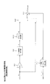
- FIG. 6 is a block diagram illustrating details of the second torque target value setting process according to the first embodiment.
- FIG. 7 is a diagram illustrating a time-dependent change of each parameter in the stop control by the second torque target value setting process of the present embodiment.
- FIG. 1 is a block diagram showing a main configuration of an electric vehicle provided with an electric vehicle control system according to an embodiment of the present invention.
- FIG. 2 is a flowchart showing the flow of the electric vehicle control method according to the present embodiment.
- FIG. 8 is a timing chart illustrating a control result using the electric vehicle control method according to the present embodiment.
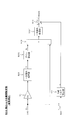
- FIG. 9 is a block diagram illustrating details of the second torque target value setting process according to the second embodiment.
- FIG. 10 is a block diagram illustrating details of the second torque target value setting process according to the comparative example.
- FIG. 11A is a timing chart illustrating the behavior of the electric vehicle when the second torque target value setting process according to the comparative example (flat road) is used.
- FIG. 11B is a timing chart for explaining the behavior of the electric vehicle when the second torque target value setting process according to the comparative example (uphill road) is used.
- FIG. 12 is a block diagram illustrating details of the second torque target value setting process according to the first modification.
- FIG. 13 is a block diagram illustrating details of the second torque target value setting process according to the second modification.
- FIG. 1 is a block diagram showing a main configuration of an electric vehicle 100 to which the control method of the present embodiment is applied.
- the electric vehicle 100 includes an electric motor 4 composed of a three-phase AC motor as a traveling drive source of the vehicle.
- the electric vehicle 100 is assumed to be any type of vehicle that travels using the driving force of the electric motor 4, such as an electric vehicle (EV), a hybrid vehicle (HEV), and a fuel cell vehicle (FCV).
- EV electric vehicle
- HEV hybrid vehicle
- FCV fuel cell vehicle
- the electric vehicle 100 is equipped with a battery 1, a motor controller 2 as a control device, an inverter 3, and an electric motor 4, which constitute the electric vehicle control system 10.
- the battery 1 is connected to the inverter 3 so as to function as a power source for supplying (discharging) driving power to the electric motor 4 while being able to be charged by receiving the supply of regenerative power from the electric motor 4. ing.
- the motor controller 2 is composed of, for example, a computer including a central processing unit (CPU), a read-only memory (ROM), a random access memory (RAM), and an input / output interface (I / O interface).
- the motor controller 2 is programmed so that each process constituting the control method according to the present embodiment can be executed.
- the motor controller 2 obtains the final motor torque command value T m ** based on the detected values of various sensors, and the inverter so that the electric motor 4 realizes the actual output torque based on the final motor torque command value T m **. 3 is operated to control the power supply to the electric motor 4.
- the details of the control by the motor controller 2 in this embodiment will be described later.
- the inverter 3 is provided with, for example, two switching elements (for example, power semiconductor elements such as IGBTs and MOS-FETs) for each phase, and the switching elements are turned on / off according to a drive signal to start from the battery 1.
- the supplied direct current is converted into alternating current, and a desired current is passed through the electric motor 4.
- the electric motor 4 generates a driving force by an alternating current supplied from the inverter 3, and transmits the driving force to the left and right drive wheels 9a and 9b via the speed reducer 5 and the drive shaft 8. Further, the electric motor 4 recovers the kinetic energy of the vehicle as electric energy by generating a regenerative driving force when the electric motor 4 is rotated by the drive wheels 9a and 9b while the vehicle is traveling.
- the inverter 3 converts the alternating current generated during the regenerative operation of the electric motor 4 into a direct current and supplies it to the battery 1.
- the rotation sensor 6 is composed of, for example, a resolver, an encoder, or the like, and detects the rotor phase ⁇ of the electric motor 4. Further, the rotation sensor 6 outputs the detected rotor phase ⁇ to the motor controller 2.
- the current sensor 7 detects the motor current (iu, iv, iwa) as the three-phase alternating current of the electric motor 4. Further, the current sensor 7 outputs the detected motor current (iu, iv, iwa) to the motor controller 2. Since the sum (iu + iv + iwa) of each component of the motor current (iu, iv, iwa) which is a three-phase AC is 0, the current sensor 7 detects the current of any two phases and the remaining one phase. The current may be calculated.
- FIG. 2 is a flowchart showing the flow of the control method of the present embodiment.
- the processing of this flowchart is executed by the motor controller 2 at predetermined calculation cycles. That is, the motor controller 2 is programmed to execute the processes related to steps S100 to S206 shown in FIG. 2 at predetermined calculation cycles.
- step S100 the motor controller 2 executes an input process for acquiring each signal indicating the vehicle state.
- the signals to be acquired include the accelerator opening AP [%], the rotor phase ⁇ [rad] of the electric motor 4, the motor rotation speed ⁇ m [rad / s], the motor rotation speed N m [rpm], and the vehicle speed V [km. / H], the motor current (iu, iv, iwa) [A], and the DC voltage value Vdc [V] between the battery 1 and the inverter 3.
- the accelerator opening AP (%) is acquired as a detection value of an accelerator opening sensor (not shown). Further, the rotor phase ⁇ of the electric motor 4 is acquired as a detection value of the rotation sensor 6.
- the motor rotation speed ⁇ m which is the mechanical angular velocity of the electric motor 4, is acquired based on the rotor phase ⁇ . More specifically, the motor controller 2 obtains the electric angular velocity ⁇ e of each motor by time-differentiating the rotor phase ⁇ , and divides the motor electric angular velocity ⁇ e by the number of pole pairs of the electric motor 4 to obtain the motor rotational speed ⁇ . m Acquire as [rad / s].
- the motor rotation speed N m is acquired based on the motor rotation speed ⁇ m . More specifically, the motor controller 2 acquires a value obtained by multiplying the motor rotation speed ⁇ m by the unit conversion coefficient (60 / 2 ⁇ ) as the motor rotation speed N m [rpm].
- vehicle speed V is calculated based on the motor rotation speed ⁇ m .
- the method of calculating the vehicle speed V will be described later. In the following, in order to clearly show that the vehicle speed V is a time-dependent function, this is sometimes referred to as “vehicle speed V (t)”.
- the motor current (iu, iv, iw) is acquired as a detected value of the current sensor 7.
- the DC voltage value Vdc is acquired as a detection value of a voltage sensor (not shown) provided in the DC power supply line between the battery 1 and the inverter 3.
- step S110 the motor controller 2 executes the torque command value setting process. That is, the motor controller 2 sets the final motor torque command value T m ** based on the accelerator opening AP and the motor rotation speed ⁇ m .
- the motor controller 2 of the present embodiment calculates a first torque target value T m1 * for control during normal driving and a second torque target value T m2 * for control during stop, and any one of these is calculated. Is set as the final motor torque command value T m ** .
- the first torque target value T m1 * is a control time (hereinafter, "non-stop") that is not a stop control such as normal running of the electric vehicle 100 (a state in which the electric vehicle 100 is running at an output in line with the driver's request). It is a torque target value calculated mainly from the viewpoint of realizing the actual output torque of the electric motor 4 according to the amount of accelerator operation by the driver in (also referred to as “time control”).
- the second torque target value T m2 * is an electric vehicle so as not to make the occupants of the electric vehicle 100 feel a sudden stop in the control for stopping the electric vehicle 100 (hereinafter, also referred to as "stop control"). It is a target value of torque determined from the viewpoint of adjusting the acceleration a (or deceleration a d ) of 100. That is, the second torque target value T m2 * is calculated from the viewpoint of smooth deceleration just before the electric vehicle 100 stops.
- step S120 the motor controller 2 executes the current command value calculation process. Specifically, the motor controller 2 refers to a predetermined table based on the motor rotation speed ⁇ m , the DC voltage value V dc , and the final motor torque command value T m ** set in step S110, and dq. Calculate the axial current target value ( id * , i q * ).
- step S130 the motor controller 2 executes the current control process. Specifically, the motor controller 2, first, the motor current (iu, iv, iw) and on the basis of the rotor phase alpha, calculates the dq-axis current value (i d, i q).
- the motor controller 2 the dq-axis current value (i d, i q) and dq-axis current target value calculated in step S120 (i d *, i q *) and dq-axis voltage command value from the deviation of ( Calculate v d , v q ).
- the non-interfering voltage required for canceling the interfering voltage between the dq orthogonal coordinate axes may be added to the calculated dq axis voltage command value (v d , v q ).
- the motor controller 2 converts the dq axis voltage command value (v d , v q ) from the dq coordinate system to the uvw coordinate system by using the rotor phase ⁇ , so that the three-phase AC voltage command value (v d , vv) is generated. , Vw) is calculated.
- the motor controller 2 generates a PWM signal (tu, tv, tw) [%] based on the calculated three-phase AC voltage command value (vu, vv, vw) and the DC voltage value Vdc, and uses this as the inverter 3. Output to. Further, an inverter controller (not shown) opens and closes the switching element of the inverter 3 based on the PWM signal (tu, tv, tw). As a result, the power supply to the electric motor 4 is adjusted so that the electric motor 4 is driven by the actual output torque based on the final motor torque command value T m ** .
- step S110 The torque command value setting process in step S110 will be described in more detail below.
- FIG. 3 is a block diagram illustrating the function of the motor controller 2 that performs the torque command value setting process.
- the motor controller 2 includes a first torque target value setting unit B200, a second torque target value setting unit B210, and a max select unit B220 as a configuration for realizing a function of executing a torque command value setting process. , And the previous value acquisition unit B230.
- the first torque target value setting unit B200 calculates the first torque target value T m1 * based on the accelerator opening AP and the motor rotation speed ⁇ m .
- FIG. 4 is a block diagram illustrating a more detailed function of the first torque target value setting unit B200.
- the first torque target value setting unit B200 includes a torque table target value setting unit B201, a gradient torque estimation unit B202, and an addition unit B203.
- the torque table target value setting unit B201 calculates the torque table target value T m1 by referring to a predetermined accelerator opening degree-torque table based on the accelerator opening degree AP and the motor rotation speed ⁇ m .
- FIG. 5 shows an example of an accelerator opening-torque table.
- the torque table target value T m1 is set to a larger value as the accelerator opening AP increases according to the magnitude of the motor rotation speed ⁇ m .
- the torque table target value T m1 is set to a positive value.
- the torque table target value T m1 is set to a negative value in order to decelerate the electric vehicle 100.
- the accelerator opening-torque table is stored in advance in a storage area (not shown) of the motor controller 2.
- the torque table target value setting unit B201 outputs the calculated torque table target value T m1 to the addition unit B203.
- the gradient torque estimation unit B202 calculates the gradient torque estimation value T ds based on the motor rotation speed ⁇ m and the final torque command value previous value T m_pr ** .
- the final torque command value previous value T m_pr ** is the value of the final motor torque command value T m ** calculated in the previous control cycle.
- the gradient torque estimation unit B202 first calculates the first motor torque estimation value by filtering the motor rotation speed ⁇ m with a filter based on an appropriate vehicle model according to the electric vehicle 100.
- the gradient torque estimation unit B202 applies a low-pass filter to the final torque command value previous value T m_pr ** to calculate the second motor torque estimation value.
- the gradient torque estimation unit B202 subtracts the first motor torque estimated value from the second motor torque estimated value, and performs appropriate filtering processing on the value obtained by the subtraction to perform the gradient torque estimated value T. Find ds .
- the gradient torque estimated value T ds is electric from the final torque command value T m_pr ** corresponding to the actual output torque of the electric motor 4 and the motor rotation speed ⁇ m corresponding to the actual rotation speed of the electric motor 4. It is a parameter calculated as a difference between the theoretical output torque determined according to the vehicle model of the vehicle 100 and the vehicle model.
- the gradient torque estimated value T ds of the present embodiment is the theoretical output torque determined from the actual output torque of the electric vehicle 100 and the ideal vehicle model according to the magnitude of the gradient of the traveling path of the electric vehicle 100. It is a parameter representing the deviation between and.
- the gradient torque estimation unit B202 outputs the calculated gradient torque estimation value T ds to the addition unit B203.
- the addition unit B203 adds the gradient torque estimated value T ds to the torque table target value T m1 to obtain the first torque target value T m1 * . Then, the addition unit B203 outputs the calculated first torque target value T m1 * to the max select unit B220.
- the second torque target value setting unit B210 calculates the second torque target value T m2 * used in the stop control based on the accelerator opening AP and the motor rotation speed ⁇ m . The details of the calculation of the second torque target value T m2 * will be described later.
- the second torque target value setting unit B210 outputs the calculated second torque target value T m2 * to the max select unit B220.
- the max select unit B220 finalizes the larger of the first torque target value T m1 * from the first torque target value setting unit B200 and the second torque target value T m2 * from the second torque target value setting unit B210. Set as the motor torque command value T m ** . If the first torque target value T m1 * and the second torque target value T m2 * are the same value, the value is set as the final motor torque command value T m ** .
- the first torque target value T m1 * is the final motor torque command value T m * by the max select unit B220 .
- Non-stop control set as * is executed.
- the stop control in which the second torque target value T m2 * is set as the final motor torque command value T m ** is executed. Will be done.
- the max select unit B220 outputs the process of step S120 in FIG. 2 and the previous value acquisition unit B230 based on the set final motor torque command value T m ** .
- the previous value acquisition unit B230 acquires the final motor torque command value T m ** from the max select unit B220 as the final torque command value previous value T m_pr ** . Then, the previous value acquisition unit B230 returns the acquired final torque command value previous value T m_pr ** to the first torque target value setting unit B200 and the second torque target value setting unit B210.
- the electric vehicle 100 basically has a first torque target value T m1 * > a second torque target value T m2 * during non-stop control such as during normal driving . Then, the first torque target value T m1 * based on the driver's request is set as the final motor torque command value T m ** .
- the first torque target value T m1 * becomes negative according to the accelerator opening-torque table of FIG. Is set to the value of. In this way, by setting the negative first torque target value T m1 * , the vehicle speed V also continuously decreases. Then, at the timing when the vehicle speed V reaches the predetermined switching vehicle speed V sw (hereinafter, also simply referred to as “torque switching timing”), the first torque target value T m1 * and the second torque target value T m2 * mutually. Approximately equal.
- the motor controller 2 executes non-stop control when the vehicle speed V ⁇ switching vehicle speed V sw , and executes stop control when the vehicle speed V> switching vehicle speed V sw .
- FIG. 10 is a block diagram illustrating details of the function of the second torque target value setting unit B210 in the comparative example.
- the second torque target value setting unit B210 of the comparative example has a gain multiplication unit B311, a primary delay processing unit B312, a gradient torque setting unit B313, and an addition unit B314.
- the gain multiplication unit B311 multiplies the motor rotation speed ⁇ m [rad / s] by the fixed gain K vf to obtain the parameters K vf ⁇ ⁇ m [N ⁇ m].
- the fixed gain K vf is a negative fixed value determined from the viewpoint of smoothly decelerating the electric vehicle 100.
- the fixed gain K vf is predetermined by experiments or the like.
- the primary delay processing unit B312 performs primary delay processing on the parameters K vf ⁇ ⁇ m from the gain multiplication unit B311. Calculate the basic torque target value T m2 when stopped.
- the primary delay processing unit B312 performs primary delay processing using the filter represented by the following equation (1) on the parameters K vf ⁇ ⁇ m to obtain the basic torque target value T m 2 at the time of stopping.
- ⁇ in Eq. (1) is a time constant.
- the primary delay processing unit B312 outputs the obtained basic torque target value T m2 at the time of stopping to the addition unit B314.
- the gradient torque setting unit B313 obtains the gradient torque estimation value T ds based on the final torque command value previous value T m_pr ** from the previous value acquisition unit B230 by the same calculation method as the gradient torque estimation unit B202 described above. calculate.
- the gradient torque setting unit B313 calculates the gradient torque estimation value Td in the same manner as the gradient torque estimation unit B202 described above. Then, the gradient torque setting unit B313 determines the gradient of the road surface based on the value of the gradient torque estimated value T d , and multiplies the determined gradient by a predetermined gain to obtain the gradient torque estimated value T ds . Then, the gradient torque setting unit B313 outputs the obtained gradient torque estimated value T ds to the addition unit B314.
- the addition unit B314 adds the gradient torque estimated value T ds from the gradient torque setting unit B313 to the basic torque target value T m2 when stopped from the primary delay processing unit B312, so that the second torque target value T m2 * Ask for. Then, the second torque target value T m2 * is output to the max select unit B220 described with reference to FIG.
- the change in the deceleration a d of the electric vehicle 100 during stop control is suppressed by using the fixed gain K vf predetermined according to the characteristics of the electric vehicle 100. Therefore, a smooth stop of the electric vehicle 100 is realized.
- the present inventors have noted that in the configuration of this comparative example, there are scenes in which it cannot be said that the sudden stop feeling given to the occupant of the electric vehicle 100 can be sufficiently suppressed. The reason will be explained in more detail.
- FIG. 11A is a timing chart showing a control result of the electric vehicle 100 based on the configuration of the comparative example.
- FIG. 11A shows a control result in a scene in which the electric vehicle 100 is traveling on an uphill road.
- FIG. 11A (a) shows the time course of the vehicle speed V (t). Further, FIG. 11A (b) shows the time course of the final motor torque command value T m ** . Further, FIG. 11A (c) shows the time course of G acting on the occupant of the electric vehicle 100. Further, FIG. 11 (d) shows the time course of the jerk j (t) [m / s 3 ].
- the jerk j (t) of the electric vehicle 100 is a value defined as the first derivative with respect to the time of acceleration a (t), and is "jerk” or “acceleration”. It is a physical quantity also called.
- the first torque target value T based on the accelerator operation of the driver who desires to stop the electric vehicle 100 from the time t0 to the torque switching timing time t3.
- m1 * ( ⁇ 0) is set as the final motor torque command value T m ** .
- the vehicle speed V decreases based on the fact that the negative final motor torque command value T m ** is set (see FIG. 11A (a)).
- the vehicle speed V reaches the switching speed V sw at time t3
- the first torque target value T m1 * is smaller than the * second torque target value T m @ 2
- the final motor torque command value T m ** changes abruptly due to the switching from the first torque target value T m1 * to the second torque target value T m2 * .
- the change in G at the torque switching timing at time t3 is not smooth (see FIG. 11A (c)), and due to this, the jerk j (t) temporarily increases in the vicinity of time t3. (See FIG. 11A (d)).
- the present inventors have found that the peak P of the jerk j (t) may give a feeling of sudden stop to the occupant of the electric vehicle 100.
- the torque switching timing at which the first torque target value T m1 * becomes equal to or less than the second torque target value T m2 * is the time t1 earlier than that when traveling on a flat road. Then, even when traveling on an uphill road, after the time t1 which is the torque switching timing, the final motor torque command value T m ** stops the electric vehicle 100 while drawing a profile of a first-order lag curve according to the time constant ⁇ . It will converge to the target value for making it.
- the second torque target value T m2 * is a gradient torque estimated value T according to the slope of the uphill road with respect to the basic torque target value T m2 at the time of stopping based on the motor rotation speed ⁇ m. It is calculated by adding ds (> 0) (see the addition part B314 in FIG. 10). Therefore, the target value of the torque for stopping the electric vehicle 100 is set to be larger by the gradient torque estimated value T ds than that (that is, 0) when traveling on a flat road (see FIG. 11B (b)).
- the second torque target value T m2 * (final motor torque command value T m ** ) is the primary delay processing unit B312 even in the control scene when traveling on an uphill road. Is calculated by one-delay processing based on the same time constant ⁇ . That is, even when traveling on an uphill road, the control for converging the final motor torque command value T m ** to the target value is executed at substantially the same time as when traveling on a flat road. Therefore, the final motor torque command after time t1 The change in value T m ** becomes steeper (see FIG. 11B (b)).
- FIG. 6 is a block diagram illustrating details of the function of the second torque target value setting unit B210 in the present embodiment. If necessary, the same elements as in the comparative example are designated by the same reference numerals, and the description thereof will be omitted.
- the second torque target value setting unit B210 of the present embodiment includes a vehicle speed conversion unit B211, a primary delay processing unit B212, a threshold vehicle speed setting unit B213, a magnitude determination unit B214, and a gain calculation unit B215. It has a fixed gain setting unit B216, a switching unit B217, a multiplication unit B218, a gradient torque setting unit B219, and an addition unit B2111.
- the vehicle speed conversion unit B211 calculates the vehicle speed conversion value K c ⁇ ⁇ m [km / h] by multiplying the motor rotation speed ⁇ m [rad / s] by a predetermined conversion gain K c .
- the converted gain K c is a value appropriately determined from the viewpoint of converting the unit of the motor rotation speed ⁇ m into the unit of speed and correcting it to a value close to the actual vehicle speed of the electric vehicle 100.
- the conversion gain K c can be determined by the tire load radius r, the gear ratio N of the final gear in the reduction gear 5, and the unit conversion coefficient 3600/1000.
- the vehicle speed conversion unit B211 sets the wheel rotational speed w of the electric vehicle 100 as viewed as a vehicle speed V, and conversion gain K c to (r / N) ⁇ (3600/1000 ). Then, the vehicle speed conversion unit B211 outputs the obtained vehicle speed conversion value K c ⁇ ⁇ m to the primary delay processing unit B212.
- the primary delay processing unit B212 obtains the vehicle speed V based on the vehicle speed conversion values K c ⁇ ⁇ m from the vehicle speed conversion unit B211. Specifically, the primary delay processing unit B212 performs primary delay processing based on the filter represented by the above equation (1) on the vehicle speed conversion value K c ⁇ ⁇ m to obtain the vehicle speed V (t). As a result, the vehicle speed V (t) is determined as a function of time corresponding to the first-order lag curve of the time constant ⁇ . Specifically, the vehicle speed V (t) is expressed by the following equation (2).
- V 0 is a constant determined according to the initial condition of V (t).
- the primary delay processing unit B212 outputs the obtained vehicle speed V (t) to the magnitude determination unit B214 and the gain calculation unit B215.
- the threshold vehicle speed setting unit B213 outputs the threshold value vehicle speed V th recorded in advance in the memory or the like in the motor controller 2 to the magnitude determination unit B214.
- the significance of the threshold vehicle speed V th will be described later.
- the magnitude determination unit B214 determines the magnitude between the vehicle speed V (t) from the primary delay processing unit B212 and the threshold vehicle speed V th from the threshold vehicle speed setting unit B213.
- the magnitude determination unit B214 outputs the binary signal Bs corresponding to the determination result to the switching unit B217. Specifically, when the magnitude determination unit B214 determines that the vehicle speed V (t) is larger than the threshold vehicle speed V th , the binary signal Bs is "1", and if not, the binary signal Bs is "0". Is output to the switching unit B217.
- the gain calculation unit B215 calculates the variable gain K vv based on the vehicle speed V (t) from the primary delay processing unit B212.
- the gain calculation unit B215 sets the variable gain K vv as a function of the time t represented by the following equation (3).
- M V in the formula means an equivalent mass of the electric vehicle 100.
- Equivalent mass M V of the electric vehicle 100 is a physical quantity that is determined on the basis of body mass M, the gear ratio of the final gear N, the driving wheel inertia J w, and the motor inertia J m. Further, “r” in the formula is the load radius of the tire.
- the gain calculation unit B215 in the present embodiment determines the variable gain K vv of the above equation (3) so that the jerk j (t) takes a fixed jerk value k j that does not depend on the time t.
- the gain calculation unit B215 differentiates the vehicle speed V (t) represented by the above equation (2) to obtain the acceleration a (t) represented by the following equation (4).
- the gain calculation unit B215 differentiates the acceleration a (t) of the above equation (4) to obtain the jerk j (t) represented by the following equation (5).
- the gain calculation unit B215 performs acceleration a (t) and vehicle speed V (t) under the condition that the jerk j (t) takes a fixed jerk value k j in the equations (3) to (5). Ask for.
- the gain calculation section B215 has the formula (5) jerk in j (t) the acceleration a (t k) at time t k at the time when the take jerk fixed value k j (hereinafter, “acceleration reference value a k “and also referred to) and in the vehicle speed V (t k) (hereinafter may seek also referred) to as” vehicle speed reference value V k. "acceleration reference value a k "and also referred to) and in the vehicle speed V (t k) (hereinafter may seek also referred) to as” vehicle speed reference value V k.
- the jerk fixed value k j the acceleration reference value a k , and the vehicle speed reference value V k are the following equations (6) to (5), respectively. It is expressed as (8).
- the time t k is eliminated based on the above equations (6) to (8), and the vehicle speed reference value V k and the acceleration reference value a k are determined as the following equations (9) and (10).
- the functional acceleration a (t) and vehicle speed V (t) specified in this way are distinguished from the acceleration a (t) of the above formula (4) and the vehicle speed V (t) of the formula (2). Therefore, they are referred to as "acceleration a'(t)" and "vehicle speed V'(t)", respectively.
- variable gain K vv can be determined by appropriately applying the above equations (12) to (15) to the equation (3).
- the deceleration a d ′ (t) of the equation (15) is applied to the part of the acceleration a (t) of the equation (3) by reversing the sign, and the vehicle speed V ′ (t) is applied to the vehicle speed of the equation (3).
- V (t) the variable gain K vv is expressed as a function of the vehicle speed V'(t).
- the variable gain K vv is expressed by the following equation (16).
- the gain calculation unit B215 outputs the obtained variable gain K vv to the switching unit B217.
- the fixed gain setting unit B216 outputs the fixed gain K vf recorded in advance in the memory or the like in the motor controller 2 to the switching unit B217.
- the fixed gain K vf is set to a constant value that does not depend on the change in the vehicle speed V (t), similarly to the fixed gain K vf described in the above comparative example.
- the switching unit B217 transfers the variable gain K vv from the gain calculation unit B215 or the fixed gain K vf from the fixed gain setting unit B216 to the multiplication unit B218 based on the binary signal Bs from the magnitude determination unit B214. Output.
- the switching unit B217 receives the binary signal Bs "1" from the magnitude determination unit B214 (that is, when the vehicle speed V (t)> the threshold vehicle speed V th ), the switching unit B217 is multiplied by the variable gain K vv . Output to unit B218.
- the switching unit B217 receives the binary signal Bs "0" from the magnitude determination unit B214 (when the vehicle speed V (t) ⁇ the threshold vehicle speed V th )
- the switching unit B217 outputs a fixed gain K vf to the multiplication unit B218. To do.
- the gain for calculating the second torque target value T m2 * according to the magnitude relationship between the vehicle speed V (t) and the threshold vehicle speed V th (hereinafter, “jerk adjustment processing gain K v ””.
- Variable gain K vv or fixed gain K vf is set as (also referred to as).
- the multiplication unit B218 multiplies the jerk adjustment processing gain K v from the switching unit B217 by the motor rotation speed ⁇ m to obtain the basic torque target value T m 2 when stopped. Then, the multiplication unit B218 outputs the obtained basic torque target value T m2 at the time of stopping to the addition unit B2111.
- the gradient torque setting unit B219 calculates the gradient torque estimated value T ds based on the final torque command value previous value T m_pr ** from the previous value acquisition unit B230 in FIG.
- the calculation method of the gradient torque estimated value T ds is the same as the calculation method in the gradient torque setting unit B313 described above.
- the addition unit B2111 adds the gradient torque estimation value T ds from the gradient torque setting unit B219 to the stop basic torque target value T m2 from the multiplication unit B218 to obtain the second torque target value T m2 * . Then, the addition unit B2111 outputs the obtained second torque target value T m2 * to the max select unit B220 of FIG.
- FIG. 7 is a diagram illustrating changes in each parameter of the electric vehicle 100 due to the processing of the second torque target value setting unit B210.
- the second torque target value T m2 * is set based on the stop basic torque target value T m2 obtained by multiplying the motor rotation speed ⁇ m by the variable gain K vv .
- the first is based on the stop basic torque target value T m 2 obtained by multiplying the motor rotation speed ⁇ m by the fixed gain K vf . 2 Torque target value T m2 * is set.
- variable gain K vv is set and the jerk j (t) is limited to the jerk fixed value k j . Therefore, the electric vehicle 100 decelerates based on the acceleration a (deceleration a d ) in which the jerk j (t) is maintained at the jerk fixed value k j .
- a fixed gain K vf is set as the jerk adjustment processing gain K v in the latter half after the vehicle speed V (t) reaches the threshold vehicle speed V th .
- the electric vehicle 100 decelerates while taking a profile of a primary delay in which the jerk j and the acceleration a (deceleration a d ) gradually decrease to 0 as the vehicle speed V decreases. ..
- the threshold vehicle speed V th for defining the timing for switching the jerk adjustment processing gain K v from the variable gain K vv to the fixed gain K vf (hereinafter, also referred to as “gain switching timing”) is
- the jerk j (t) determined based on the fixed gain K vf set in the latter half of the stop control is predetermined with respect to the jerk fixed value k j based on the variable gain K vv set in the first half of the stop control. It is set to a value of vehicle speed V that falls within the range.
- the threshold vehicle speed V th, the vehicle speed reference value is a vehicle speed V at the time t k to jerk j of the second half of the stop control is substantially coincident with the jerk fixed value k j of the first half of the stop control Set to V k .
- FIG. 8 is a timing chart for explaining the control result using the control method according to the present embodiment.
- FIG. 8 shows a control result in a scene in which the electric vehicle 100 is traveling on an uphill road.
- the control result in the scene where the electric vehicle 100 is traveling on the uphill road in the comparative example is shown by a broken line.
- the 8 (a), 8 (b), 8 (c), and 8 (d) show the vehicle speed V (t), the final motor torque command values T m ** , G, and jerk, respectively. It shows the time course of degree j (t). Further, the time t0 represents the torque switching timing (that is, the start timing of the stop control) in the control result of the present embodiment, and the time t2 represents the gain switching timing (that is, the timing of shifting from the first half to the second half of the stop control). Represent.
- the second torque target value T m2 * (according to the control logic described with reference to FIG. Since the final motor torque command value T m ** is determined based on the variable gain K vv , the final motor torque command value T m ** increases substantially linearly with respect to time t (FIG. 8 (b). )reference). Therefore, the jerk j (t) from time t0 to time t2 is limited to the jerk fixed value k j or less (see FIG. 8 (d)).
- the jerk j (t) is maintained at a fixed jerk value k j . Therefore, a sudden change in G from time t0 to time t2 can be suppressed (see FIG. 8C). That is, it prevents the occurrence of an excessive jerk j at the torque switching timing as shown in the control result of the comparative example shown by the broken line (see the broken line in FIG. 8D), and gives the occupant of the electric vehicle 100 a feeling of sudden stop. It can be suppressed.
- the vehicle speed V (t) reaches the threshold vehicle speed V th at the time t2, which is the gain switching timing (see FIG. 8A). Therefore, after the time t2, which is the latter half of the stop control, the second torque target value T m2 * is determined based on the fixed gain K vf according to the control logic described in FIG.
- the jerk j and the deceleration a d are profiled with a first-order lag that gradually decreases to 0 as the vehicle speed V decreases. That is, in the latter half of the stop control, as in the case of the comparative example, a smooth stop that gives almost no sudden stop feeling to the occupant is realized.
- a control method for the electric vehicle 100 that executes stop control (see FIG. 6) for decelerating and stopping the electric vehicle 100 by the regenerative braking force of the electric motor 4.
- the stop control control when the second torque target value T m2 * > the first torque target value T m1 *
- the vehicle speed V exceeds the threshold vehicle speed V th (from jerk B214 to 2 in FIG. 6).
- the deceleration of the electric vehicle 100 is performed.
- the threshold vehicle speed V th is determined by the difference between the fixed jerk value k j as the jerk j set in the second jerk adjustment process and the jerk j set in the first jerk adjustment process. It is set to the value of the vehicle speed V (vehicle speed reference value V k ) when it becomes the following.
- the jerk j is limited to the jerk fixed value k j or less, so that the peak of the jerk j can be suppressed. it can. Therefore, it is possible to suppress the feeling of sudden stop given to the occupant of the electric vehicle 100 due to the jerk j becoming an excessively high value.
- the jerk so that the deceleration a d and the jerk j of the electric vehicle 100 gradually decrease to 0 as the vehicle speed V decreases. Adjust j. Therefore, in the latter half of the stop control, the process of reducing the jerk j is continuously executed from the first half of the stop control in which the jerk j is limited. Therefore, the magnitude of the jerk j is suppressed even in the latter half of the stop control, so that the electric vehicle 100 can be stopped smoothly.
- the threshold vehicle speed V th is equal to or less than a predetermined value, particularly 0, when the difference between the fixed jerk value k j in the second jerk adjustment process and the jerk j in the first jerk adjustment process is equal to or less than a predetermined value. It is set to the value of the vehicle speed V of. That is, the threshold vehicle speed V th is the value of the vehicle speed V at time t k at which the jerk j determined by the calculation logic (calculation based on the fixed gain K vf ) in the first jerk adjustment process becomes equal to the jerk fixed value k j ( It is set to the vehicle speed reference value V k ). It should be noted that such a threshold vehicle speed V th can be predetermined by experiments or the like.
- the step of the jerk j at the time of switching between the first jerk adjustment process and the second jerk adjustment process (gain switching timing) can be suppressed. That is, it is possible to suppress the change in the deceleration a d when the control is switched. Therefore, the switching of the control can be executed without giving the occupant of the electric vehicle 100 a feeling of sudden stop.
- control method of the present embodiment appropriately suppresses the peak even when traveling on an uphill road where the peak of jerk j becomes larger in the above-mentioned reference example, and gives the occupant of the electric vehicle 100 a feeling of sudden stop. It is possible to suppress giving. That is, the control method of the present embodiment exerts a more remarkable effect in the scene where the electric vehicle 100 is traveling on an uphill road.
- the stop control is performed by multiplying the vehicle speed conversion value K c ⁇ ⁇ m as a speed parameter proportional to the vehicle speed by the jerk adjustment processing gain K v as a predetermined gain.
- This includes a motor torque command value setting step (steps S110 and FIG. 6 in FIG. 2) for setting a second torque target value T m2 * as a motor torque command value corresponding to the regenerative braking force.
- the first jerk adjustment process is executed by setting the jerk adjustment process gain K v to a variable gain K vv as a variable value whose absolute value becomes smaller as the vehicle speed V increases (gain calculation unit B215 and).
- the second jerk adjustment process is executed by setting the jerk adjustment process gain K v to a fixed gain K vf which is a constant fixed value with respect to a change in vehicle speed V (fixed gain setting unit B216).
- the primary delay processing unit B212 is executed by setting the jerk adjustment process gain K v to a fixed gain K vf which is a constant fixed value with respect to a change in vehicle speed V.
- the jerk j is limited to the fixed jerk value k j or less in the first half of the stop control, while the deceleration a d and the jerk j gradually decrease to 0 as the vehicle speed V decreases in the second half.
- the behavior of the electric vehicle 100 can be realized by a simple control logic.
- the electric vehicle control system 10 including the motor controller 2 as a stop control device for decelerating and stopping the electric vehicle 100 by the regenerative braking force of the electric motor 4 is provided.
- the motor controller 2 determines the jerk j of the electric vehicle 100. It has a first jerk adjusting unit (gain calculation unit B215, switching unit B217, and multiplication unit B218) that adjusts to a jerk fixed value k j or less, which is an upper limit value.
- a first jerk adjusting unit gain calculation unit B215, switching unit B217, and multiplication unit B218, that adjusts to a jerk fixed value k j or less, which is an upper limit value.
- the threshold vehicle speed V th is the value of the vehicle speed V (vehicle speed reference value V) when the difference between the jerk j in the second jerk adjustment unit and the jerk j in the first jerk adjustment unit is equal to or less than a predetermined value. It is set to k ).
- FIG. 9 is a block diagram illustrating the function of the second torque target value setting unit B210 according to the present embodiment.
- the second torque target value setting unit B210 in the present embodiment includes a gain setting unit B2112 in place of the magnitude determination unit B214, the gain calculation unit B215, and the switching unit B217 in the first embodiment. ..
- the gain setting unit B2112 is preliminarily configured in a storage area (not shown) in the motor controller 2. Specifically, the gain setting unit B2112 has a vehicle speed-gain table that defines a correspondence relationship between the value of the vehicle speed V (t) and the jerk adjustment processing gain K v determined accordingly.
- the vehicle speed-gain table is configured as shown in Table 1 below.
- the vehicle speed-gain table stores the vehicle speed V equal to or less than the threshold vehicle speed V th and the fixed gain K vf in correspondence with each other, and also stores the vehicle speed V exceeding the threshold vehicle speed V th and the variable gain calculated in advance accordingly.
- K vv is associated and memorized.
- the gain setting unit B2112 refers to the vehicle speed-gain table based on the vehicle speed V from the primary delay processing unit B212, sets a variable gain K vv or a fixed gain K vf according to the vehicle speed V, and sets a multiplication unit. Output to B218.
- the same control method can be executed without executing the calculation by the gain calculation unit B215 in the above embodiment in real time. it can.
- the jerk adjustment processing gain K v is referred to a vehicle speed-gain table in which the jerk adjustment processing gain K v determined according to the vehicle speed V (t) and the jerk adjustment processing gain K v is associated with each other. Set by.
- the electric vehicle control method and the electric vehicle control system 10 of the present invention are mainly applied to the electric vehicle 100 including one electric motor 4
- the control method and control system of the above embodiment can be applied to an electric vehicle 100 including a plurality of electric motors 4 such as a 4WD vehicle with some modifications.
- the final motor torque command value T m ** obtained by the method of the above embodiment is distributed to each electric motor 4 by an appropriate distribution gain. The same effect as that of the above embodiment can be obtained in the electric vehicle 100.
- the configuration of the above embodiment is electric such as a hybrid vehicle equipped with a fuel cell (solid polymer fuel cell, solid oxide fuel cell, etc.), or a series hybrid vehicle equipped with an engine to be driven for power generation. It can also be applied to an electric vehicle 100 equipped with a power generation device that generates driving power for the motor 4.
- a fuel cell solid polymer fuel cell, solid oxide fuel cell, etc.
- a series hybrid vehicle equipped with an engine to be driven for power generation. It can also be applied to an electric vehicle 100 equipped with a power generation device that generates driving power for the motor 4.
- the threshold vehicle speed V th is such that the jerk fixed value k j set in the first jerk adjustment process and the jerk j set in the second jerk adjustment process are both fixed jerk values.
- An example of setting as a vehicle speed reference value V k which is a value of the vehicle speed V corresponding to k j , has been described.
- the threshold vehicle speed V th is not limited to being set to a vehicle speed V in which the jerk fixed value k j of the first jerk adjustment process and the jerk j (t) of the second jerk adjustment process exactly match. It may be set with a width of.
- the difference between the jerk j in the second jerk adjustment process and the fixed jerk value k j in the first jerk adjustment process before and after the gain switching timing is a predetermined value that does not give the occupant a feeling of sudden stop.
- the value of the vehicle speed V at the time may be set as the threshold vehicle speed V th .
Landscapes
- Engineering & Computer Science (AREA)
- Transportation (AREA)
- Mechanical Engineering (AREA)
- Power Engineering (AREA)
- Chemical & Material Sciences (AREA)
- Combustion & Propulsion (AREA)
- Automation & Control Theory (AREA)
- Electric Propulsion And Braking For Vehicles (AREA)
Priority Applications (2)
| Application Number | Priority Date | Filing Date | Title |
|---|---|---|---|
| JP2021519212A JP7107435B2 (ja) | 2019-05-15 | 2019-05-15 | 電動車両制御方法及び電動車両制御システム |
| PCT/JP2019/019383 WO2020230302A1 (ja) | 2019-05-15 | 2019-05-15 | 電動車両制御方法及び電動車両制御システム |
Applications Claiming Priority (1)
| Application Number | Priority Date | Filing Date | Title |
|---|---|---|---|
| PCT/JP2019/019383 WO2020230302A1 (ja) | 2019-05-15 | 2019-05-15 | 電動車両制御方法及び電動車両制御システム |
Publications (1)
| Publication Number | Publication Date |
|---|---|
| WO2020230302A1 true WO2020230302A1 (ja) | 2020-11-19 |
Family
ID=73289863
Family Applications (1)
| Application Number | Title | Priority Date | Filing Date |
|---|---|---|---|
| PCT/JP2019/019383 Ceased WO2020230302A1 (ja) | 2019-05-15 | 2019-05-15 | 電動車両制御方法及び電動車両制御システム |
Country Status (2)
| Country | Link |
|---|---|
| JP (1) | JP7107435B2 (https=) |
| WO (1) | WO2020230302A1 (https=) |
Cited By (4)
| Publication number | Priority date | Publication date | Assignee | Title |
|---|---|---|---|---|
| CN115303393A (zh) * | 2021-05-08 | 2022-11-08 | 上海钧正网络科技有限公司 | 车速控制方法、装置和电动骑行设备 |
| US20240001775A1 (en) * | 2022-06-30 | 2024-01-04 | Hyundai Motor Company | Apparatus and method for reducing jerk after an electric vehicle stops |
| US20240149703A1 (en) * | 2022-11-03 | 2024-05-09 | Ayro, Inc. | Systems and methods for controlling vehicle acceleration to regulate environmental impact |
| WO2024194988A1 (ja) * | 2023-03-20 | 2024-09-26 | 本田技研工業株式会社 | 車両制御装置、車両制御方法、およびプログラム |
Citations (6)
| Publication number | Priority date | Publication date | Assignee | Title |
|---|---|---|---|---|
| JPS6135775B2 (https=) * | 1982-08-27 | 1986-08-14 | Furukawa Electric Co Ltd | |
| JP2014111418A (ja) * | 2012-12-05 | 2014-06-19 | Daimler Ag | 電気自動車の走行制御装置 |
| JP2014155234A (ja) * | 2013-02-05 | 2014-08-25 | Fuji Electric Co Ltd | 車両の走行モータ制御システム |
| JP2014180160A (ja) * | 2013-03-15 | 2014-09-25 | Fujitsu Ten Ltd | 車両制御装置、および、車両制御方法 |
| WO2015083213A1 (ja) * | 2013-12-02 | 2015-06-11 | 日産自動車株式会社 | 電動車両の制御装置および電動車両の制御方法 |
| JP2016027278A (ja) * | 2014-06-30 | 2016-02-18 | アイシン精機株式会社 | 車両の制御装置および車両の駆動システム |
Family Cites Families (1)
| Publication number | Priority date | Publication date | Assignee | Title |
|---|---|---|---|---|
| WO2015105077A1 (ja) | 2014-01-10 | 2015-07-16 | 日産自動車株式会社 | 電動車両の制御装置および電動車両の制御方法 |
-
2019
- 2019-05-15 WO PCT/JP2019/019383 patent/WO2020230302A1/ja not_active Ceased
- 2019-05-15 JP JP2021519212A patent/JP7107435B2/ja active Active
Patent Citations (6)
| Publication number | Priority date | Publication date | Assignee | Title |
|---|---|---|---|---|
| JPS6135775B2 (https=) * | 1982-08-27 | 1986-08-14 | Furukawa Electric Co Ltd | |
| JP2014111418A (ja) * | 2012-12-05 | 2014-06-19 | Daimler Ag | 電気自動車の走行制御装置 |
| JP2014155234A (ja) * | 2013-02-05 | 2014-08-25 | Fuji Electric Co Ltd | 車両の走行モータ制御システム |
| JP2014180160A (ja) * | 2013-03-15 | 2014-09-25 | Fujitsu Ten Ltd | 車両制御装置、および、車両制御方法 |
| WO2015083213A1 (ja) * | 2013-12-02 | 2015-06-11 | 日産自動車株式会社 | 電動車両の制御装置および電動車両の制御方法 |
| JP2016027278A (ja) * | 2014-06-30 | 2016-02-18 | アイシン精機株式会社 | 車両の制御装置および車両の駆動システム |
Cited By (4)
| Publication number | Priority date | Publication date | Assignee | Title |
|---|---|---|---|---|
| CN115303393A (zh) * | 2021-05-08 | 2022-11-08 | 上海钧正网络科技有限公司 | 车速控制方法、装置和电动骑行设备 |
| US20240001775A1 (en) * | 2022-06-30 | 2024-01-04 | Hyundai Motor Company | Apparatus and method for reducing jerk after an electric vehicle stops |
| US20240149703A1 (en) * | 2022-11-03 | 2024-05-09 | Ayro, Inc. | Systems and methods for controlling vehicle acceleration to regulate environmental impact |
| WO2024194988A1 (ja) * | 2023-03-20 | 2024-09-26 | 本田技研工業株式会社 | 車両制御装置、車両制御方法、およびプログラム |
Also Published As
| Publication number | Publication date |
|---|---|
| JPWO2020230302A1 (https=) | 2020-11-19 |
| JP7107435B2 (ja) | 2022-07-27 |
Similar Documents
| Publication | Publication Date | Title |
|---|---|---|
| CN110234533B (zh) | 电动车辆的控制方法以及控制装置 | |
| CN110191818B (zh) | 电动车辆的控制方法以及电动车辆的控制装置 | |
| EP3798044B1 (en) | Control device for electric motor vehicle and control method for electric motor vehicle | |
| JP6402782B2 (ja) | 電動車両の制御装置および電動車両の制御方法 | |
| US20230249558A1 (en) | Electric vehicle control method and electric vehicle control device | |
| CN114599544B (zh) | 电动车辆的控制方法及电动车辆的控制装置 | |
| JP7056219B2 (ja) | 電動車両の制御方法および電動車両の制御装置 | |
| CN107206983B (zh) | 车辆的控制装置以及车辆的控制方法 | |
| US11932138B2 (en) | Electric vehicle control method and electric vehicle control system | |
| JP6760401B2 (ja) | 電動車両の制御方法、及び、制御装置 | |
| CN107921878A (zh) | 电动车辆的控制方法以及控制装置 | |
| CN105764742A (zh) | 电动车辆的控制装置以及电动车辆的控制方法 | |
| JP7107435B2 (ja) | 電動車両制御方法及び電動車両制御システム | |
| JP2020162373A (ja) | 電動車両の制御方法及び制御装置 | |
| JP6589554B2 (ja) | 電動車両の制御方法、及び、制御装置 | |
| JP6880674B2 (ja) | 電動車両の制御方法、及び、電動車両の制御装置 | |
| JP6649478B2 (ja) | 電動車両 | |
| JP7596773B2 (ja) | 電動車両の制御方法及び制御装置 |
Legal Events
| Date | Code | Title | Description |
|---|---|---|---|
| 121 | Ep: the epo has been informed by wipo that ep was designated in this application |
Ref document number: 19929070 Country of ref document: EP Kind code of ref document: A1 |
|
| ENP | Entry into the national phase |
Ref document number: 2021519212 Country of ref document: JP Kind code of ref document: A |
|
| NENP | Non-entry into the national phase |
Ref country code: DE |
|
| 122 | Ep: pct application non-entry in european phase |
Ref document number: 19929070 Country of ref document: EP Kind code of ref document: A1 |