WO2020218440A1 - シャープペンシル - Google Patents
シャープペンシル Download PDFInfo
- Publication number
- WO2020218440A1 WO2020218440A1 PCT/JP2020/017541 JP2020017541W WO2020218440A1 WO 2020218440 A1 WO2020218440 A1 WO 2020218440A1 JP 2020017541 W JP2020017541 W JP 2020017541W WO 2020218440 A1 WO2020218440 A1 WO 2020218440A1
- Authority
- WO
- WIPO (PCT)
- Prior art keywords
- cam
- holding
- chuck
- writing core
- writing
- Prior art date
- Legal status (The legal status is an assumption and is not a legal conclusion. Google has not performed a legal analysis and makes no representation as to the accuracy of the status listed.)
- Ceased
Links
Images


Classifications
-
- B—PERFORMING OPERATIONS; TRANSPORTING
- B43—WRITING OR DRAWING IMPLEMENTS; BUREAU ACCESSORIES
- B43K—IMPLEMENTS FOR WRITING OR DRAWING
- B43K21/00—Propelling pencils
-
- B—PERFORMING OPERATIONS; TRANSPORTING
- B43—WRITING OR DRAWING IMPLEMENTS; BUREAU ACCESSORIES
- B43K—IMPLEMENTS FOR WRITING OR DRAWING
- B43K21/00—Propelling pencils
- B43K21/02—Writing-core feeding mechanisms
- B43K21/22—Writing-cores gripping means, e.g. chucks
Definitions
- the present invention relates to a mechanical pencil.
- Patent Document 1 A holding chuck that holds the writing core inside the tip of a mechanical pencil and plays a role of feeding out the writing core by giving resistance to the movement of the writing core is known (Patent Document 1).
- An insertion hole for the writing core is formed in the holding chuck, and the writing core is held by being inserted into the insertion hole.
- the material of the holding chuck is generally a rubber material such as nitrile rubber. Therefore, the holding chuck may creep and deform over time, and the holding force may decrease. Further, the writing core has a dimensional variation in the range of 0.55 mm to 0.58 mm in the case of a product having a display diameter of 0.5 mm, for example. Therefore, due to variations in the dimensions during rubber molding, the holding force may become stronger or weaker in relation to the variations in the dimensions of the writing core.
- An object of the present invention is to provide a mechanical pencil provided with a holding chuck having a holding force that is less likely to decrease over time and has high dimensional accuracy.
- the first holding chuck has a first metal holding portion, and the writing core can be held by holding the writing core by elastic deformation of the first holding portion.
- a mechanical pencil is provided that comprises a one-holding chuck.
- the first holding portion may be composed of at least two plate-shaped members.
- the portion of the first holding portion that comes into contact with the writing core may have a curved shape.
- the first holding chuck may be formed from a plate-shaped member.
- a second holding chuck having a second holding portion capable of holding the writing core may be further provided.
- the second holding chuck may be made of non-metal.
- the second holding chuck may be arranged behind the first holding chuck.
- the second holding chuck may be arranged integrally with the first holding chuck.
- FIG. 1 is a vertical cross-sectional view of a mechanical pencil according to an embodiment of the present invention.
- FIG. 2 is an enlarged cross-sectional view of the front half of the mechanical pencil of FIG.
- FIG. 3 is an enlarged cross-sectional view of the rear half of the mechanical pencil of FIG.
- FIG. 4 is an enlarged cross-sectional view of the rotation drive mechanism.
- FIG. 5 is a schematic view illustrating the rotational drive of the rotor of the rotary drive mechanism.
- FIG. 6 is a schematic diagram illustrating the rotational drive of the rotor following FIG.
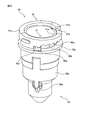
- FIG. 7 is a perspective view of the dial cam member.
- FIG. 8 is a perspective view of the rail cam member.
- FIG. 9 is another perspective view of the rail cam member.
- FIG. 1 is a vertical cross-sectional view of a mechanical pencil according to an embodiment of the present invention.
- FIG. 2 is an enlarged cross-sectional view of the front half of the mechanical pencil of FIG.
- FIG. 3 is
- FIG. 10 is a perspective view of the combined dial cam member and rail cam member.
- FIG. 11 is another perspective view of the combined dial cam member and rail cam member.
- FIG. 12 is a schematic view showing a feeding cam surface in FIG.
- FIG. 13 is a schematic view showing a feeding cam surface in FIG.
- FIG. 14 is an enlarged cross-sectional view of the front end portion of the mechanical pencil of FIG.
- FIG. 15 is a perspective view of the knock cover.
- FIG. 16 is a perspective view showing a state in which the knock cover is attached to the rear end of the mechanical pencil.
- FIG. 17 is a perspective view showing a state in which the knock cover is attached to the front end portion of the mechanical pencil.
- FIG. 18 is a perspective view of the first holding chuck.
- FIG. 19 is a perspective view of the second holding chuck.
- FIG. 20 is a perspective view of the holding chuck.
- FIG. 21 is a diagram illustrating the operation of the holding chuck.
- FIG. 22 is
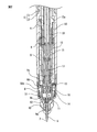
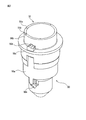
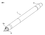
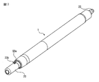
- FIG. 1 is a vertical sectional view of a mechanical pencil 1 according to an embodiment of the present invention
- FIG. 2 is an enlarged sectional view of the front half of the mechanical pencil 1 of FIG. 1
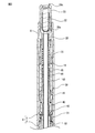
- FIG. 3 is an enlarged sectional view of the mechanical pencil 1 of FIG. It is an enlarged sectional view of the rear half.
- the mechanical pencil 1 includes a front shaft 2, a rear shaft 3 screwed onto the outer peripheral surface of the rear end portion of the front shaft 2, a mouthpiece member 4 screwed onto the outer peripheral surface of the front end portion of the front shaft 2, and a rear shaft 3. It has an inner cylinder 5 that fits on the inner peripheral surface of the rear end portion.
- the front shaft 2 and the rear shaft 3 form a shaft cylinder 6.
- the mouthpiece member 4, the inner cylinder 5, and the dial cam member 50, which will be described later, may also be referred to as a shaft cylinder 6.
- the mechanical pencil 1 is configured such that the writing core 7 protrudes from the tip of the mouth member 4.
- the vicinity of the tip of the writing core 7 is covered with a tip pipe 8 that guides the writing core 7.
- the writing core 7 side is defined as the "front" side
- the side opposite to the writing core 7 side is defined as the "rear" side.
- a slider 9 is arranged inside the front end portion of the barrel 6 so as to be slidable in the axial direction and rotatable around the axial line.
- the slider 9 is formed in a cylindrical shape whose outer diameter gradually decreases toward the front.
- a tip pipe 8 is attached to the tip 9a of the slider 9.
- a holding chuck 10 having a through hole formed in the center is arranged behind the tip pipe 8. The through hole of the holding chuck 10 slides in contact with the outer peripheral surface of the writing core 7 and acts to temporarily hold the writing core 7.
- An abutting element 9c protruding in the axial direction is integrally formed with the slider 9 at the rear portion of the outer peripheral surface of the intermediate portion 9b behind the tip portion 9a of the slider 9, particularly at the root portion of the intermediate portion 9b.
- a dial cam member 50 which is a first cam member formed in a cylindrical shape and a rail cam member 60 which is a second cam member formed in an annular shape are formed in the axial direction. They are arranged in an aligned state. A part of the tip portion 9a of the slider 9 protrudes from the hole at the front end portion of the dial cam member 50.
- the ball chuck 11 for gripping the writing core 7 and a relay member 12 formed in a cylindrical shape are arranged.
- the ball chuck 11 has a fastener 13 formed in a cylindrical shape, a chuck main body portion 14 arranged in the fastener 13, a chuck holding portion 15 formed in a cylindrical shape, and a plurality of balls 16. ing.
- a tapered surface that spreads forward is formed on the inner peripheral surface of the fastener 13.
- the chuck main body 14 is formed with a through hole for the writing core 7 along the central axis, and the front end portion of the chuck main body 14 is divided into a plurality of portions along the axial direction.
- the rear end of the chuck body 14 is held by the chuck holding portion 15.
- the chuck body portion 14 and the chuck holding portion 15 are movable in the axial direction with respect to the fastener 13.
- the plurality of balls 16 are arranged between the inner peripheral surface of the fastener 13 and the outer peripheral surface of the chuck main body 14.
- the chuck main body 14 When writing pressure is applied to the writing core 7, the chuck main body 14 abuts with the ball 16 on the tapered surface in the cylindrical fastener 13, so that the writing core 7 is gripped by the chuck main body 14. As a result, the retreat of the writing core 7 is prevented.
- the chuck main body 14 when a force for pulling out the writing core 7 acts forward, the chuck main body 14 is not affected by the fastener 13, so that the writing core 7 can be pulled forward without resistance. That is, the ball chuck 11 acts to allow the writing core 7 to move forward and prevent the writing core 7 from moving backward.
- a coil spring 17 is arranged so as to surround the chuck main body 14.
- the rear end of the coil spring 17 is fitted to the outer surface of the chuck main body 14, and the front end of the coil spring 17 is supported by a step portion formed on the inner peripheral surface of the fastener 13.
- the coil spring 17 urges the chuck body 14 rearward, and as a result, the ball chuck 11 can maintain the state in which the writing core 7 is gripped.
- a flange portion 12a is formed at the central portion of the relay member 12 in the axial direction.
- a cam contact spring 18 which is a coil spring is arranged in front of the flange portion 12a so as to surround the relay member 12. The rear end of the cam contact spring 18 is attached to the flange portion 12a of the relay member 12 (part A), and the front end of the cam contact spring 18 is attached to the inner wall of the rear end portion of the slider 9 (part A). Part B). In the axle tube 6, the cam contact spring 18 urges the slider 9 forward.
- the cam contact spring 18 acts to bring the contact element 9c provided on the slider 9 into contact with the cam surface, as will be described later.
- the rear end portion of the relay member 12 is connected to a rotation drive mechanism 30 described later.
- the front end portion of the core case 19 is fitted to the outer peripheral surface of the rear end portion of the chuck holding portion 15.
- the core case 19 is formed in a cylindrical shape, and the writing core 7 is housed inside.
- a knock rod 20 as a knock member is provided at the rear end portion of the barrel 6, specifically, the rear end portion of the inner cylinder 5 so as to be movable back and forth with respect to the barrel 6. ..
- the knock rod 20 is urged rearward by the coil spring 21.
- a partition wall portion 20a provided with a supply hole for the writing core 7 is formed in the vicinity of the rear end portion of the knock rod 20.
- An eraser 22 is detachably attached to the inside of the rear end of the knock rod 20.
- a knock cover 23 is detachably attached to the outer peripheral surface of the rear end portion of the knock rod 20 to protect the eraser 22 from dirt and the like.
- the knock rod 20 is fitted to the outer peripheral surface of the rear end portion of the core case 19.
- the core case 19 moves forward by performing a knock operation that presses the knock rod 20 or the knock cover 23 forward.
- the chuck main body portion 14 is pushed forward via the chuck holding portion 15.
- the writing core 7 gripped by the chuck main body 14 also advances, and acts to extend the writing core 7 from the tip pipe 8.
- the knock rod 20 retracts and returns to the original position due to the urging force of the coil spring 21.
- the chuck main body 14 retracts due to the urging force of the coil spring 17.
- the writing core 7 is held by the holding chuck 10 arranged in the slider 9, the writing core 7 is pulled out from the chuck main body 14 without resistance as a function of the ball chuck 11.
- the writing core 7 can be fed out by a predetermined amount each time the knock operation is repeated.
- the chuck main body portion 14 protrudes from the fastener 13 and the writing core 7 is released from being gripped. In this state, the writing core 7 drawn out from the tip pipe 8 can be pushed back with a fingertip or the like.
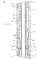
- FIG. 4 is an enlarged cross-sectional view of the rotation drive mechanism 30.
- the rotation drive mechanism 30 is arranged in the internal space of the rear shaft 3.
- the rotation drive mechanism 30 is connected to the rear end portion of the relay member 12.
- a shaft spring 31 is arranged between the rear end surface of the front shaft 2 and the front end surface of the rotation drive mechanism 30, and the rotation drive mechanism 30 is urged rearward.
- the rearward movement of the rotary drive mechanism 30 due to the urging force of the shaft spring 31 is restricted by the rear end surface of the rotary drive mechanism 30 coming into contact with the front end surface of the inner cylinder 5.
- the core case 19 penetrates the inside of the relay member 12 and the rotation drive mechanism 30 and is separated from the rotation drive mechanism 30.
- the rotation drive mechanism 30 is a cylinder 40, an upper cam forming member 41 which is a first cam forming member formed in a cylindrical shape, and a second cam forming member formed in a cylindrical shape. It has a lower cam forming member 42, a cylindrically formed cylinder member 43, a cylindrically formed torque canceller 44, and a coiled cushion spring 45. In the rotation drive mechanism 30, these members are integrated into a unit.
- the outer peripheral surface of the rear end of the relay member 12 is fitted to the inner peripheral surface of the front end of the rotor 40.
- the vicinity of the front end portion of the rotor 40 has a flange-shaped portion having a slightly larger diameter, a first cam surface 40a is formed on the rear end surface of the portion, and a second cam surface 40a is formed on the front end surface of the portion.
- the cam surface 40b is formed.
- the upper cam forming member 41 rotatably surrounds the rotor 40 behind the first cam surface 40a of the rotor 40.
- the lower cam forming member 42 is fitted to the outer peripheral surface of the front end portion of the upper cam forming member 41.
- a fixed cam surface 41a which is a first fixed cam surface, is formed on the front end surface of the upper cam forming member 41 facing the first cam surface 40a of the rotor 40.
- a fixed cam surface 42a which is a second fixed cam surface, is formed on the inner surface of the front end portion of the lower cam forming member 42 facing the second cam surface 40b of the rotor 40.
- a cylinder member 43 formed in a cylindrical shape is fitted on the outer peripheral surface of the rear end portion of the upper cam forming member 41.
- An insertion hole 43a through which the core case 19 can be inserted is formed at the rear end of the cylinder member 43.
- a torque canceller 44 which is formed in a cylindrical shape and can move in the axial direction, is arranged in the cylinder member 43.
- a cushion spring 45 is arranged between the inner surface of the front end portion of the torque canceller 44 and the inner surface of the rear end portion of the cylinder member 43. The cushion spring 45 urges the rotor 40 forward via the torque canceller 44.
- the relay member 12 transmits the backward and forward movements (cushion movements) of the writing core 7 based on the writing movements to the rotation drive mechanism 30, that is, the rotor 40, and the rotor in the rotation drive mechanism 30 generated by the cushion movements.
- the rotational movement of 40 is transmitted to the ball chuck 11 in a state where the writing core 7 is gripped. Therefore, the writing core 7 held by the ball chuck 11 also rotates.
- the rotor 40 is positioned forward by the urging force of the cushion spring 45 via the torque canceller 44, except when writing with the mechanical pencil 1, that is, when writing pressure is not applied to the writing core 7. Therefore, the second cam surface 40b of the rotor 40 comes into contact with the second fixed cam surface 42a and is brought into a meshed state.
- the ball chuck 11 retracts against the urging force of the cushion spring 45, and the rotor 40 also retreats accordingly. fall back. Therefore, the first cam surface 40a of the rotor 40 comes into contact with the first fixed cam surface 41a and is brought into a meshed state.
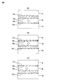
- FIG. 5 is a schematic diagram for step by step explaining the rotation driving action of the rotor 40 of the mechanical pencil 1 of FIG. 1
- FIG. 6 is a schematic diagram for explaining the rotation driving action of the rotor 40 following FIG. Is.
- a first cam surface 40a continuously serrated along the circumferential direction is formed in an annular shape, and the rotor 40 is formed.
- a second cam surface 40b that is continuously sawtoothed along the circumferential direction is formed in an annular shape.
- a first fixed cam surface 41a continuously serrated along the circumferential direction is also formed on the annular end surface of the upper cam forming member 41 facing the first cam surface 40a of the rotor 40, and the rotor 40 is formed.
- a second fixed cam surface 42a that is continuously serrated along the circumferential direction is also formed on the annular end surface of the lower cam forming member 42 that faces the second cam surface 40b.
- Each cam surface of the fixed cam surface 42a is formed so that the pitches are substantially the same as each other.
- FIG. 5A shows the relationship between the rotor 40, the upper cam forming member 41, and the lower cam forming member 42 in a state when the writing pressure is not applied to the writing core 7.
- the second cam surface 40b formed on the rotor 40 is in contact with the second fixed cam surface 42a of the lower cam forming member 42 by the urging force of the cushion spring 45.
- the first cam surface 40a of the rotor 40 and the first fixed cam surface 41a of the upper cam forming member 41 are in a half-phase (half-pitch) relationship with respect to one tooth of the cam in the axial direction. Is set to.
- FIG. 5B shows an initial state in which writing pressure is applied to the writing core 7 for writing with the mechanical pencil 1.
- the rotor 40 retracts the cushion spring 45 as the ball chuck 11 retracts.
- the rotor 40 moves toward the first fixed cam surface 41a of the upper cam forming member 41.
- FIG. 5C shows a state in which the writing pressure is further applied to the writing core 7 and the rotor 40 abuts on the first fixed cam surface 41a of the upper cam forming member 41 and retracts.
- the first cam surface 40a of the rotor 40 meshes with the first fixed cam surface 41a of the upper cam forming member 41.
- the rotor 40 receives a rotational drive corresponding to a half phase (half pitch) of one tooth of the first cam surface 40a.
- the circles drawn at the center of the rotor 40 in FIGS. 5 and 6 indicate the amount of rotational movement of the rotor 40. Then, in the state shown in FIG. 5C, the second cam surface 40b of the rotor 40 and the second fixed cam surface 42a of the lower cam forming member 42 are half-phase with respect to one tooth of the cam in the axial direction. It is set so that the relationship is shifted (half pitch).
- FIG. 6D shows an initial state in which writing with the mechanical pencil 1 is completed and the writing pressure on the writing core 7 is released.
- the rotor 40 advances by the urging force of the cushion spring 45.
- the rotor 40 moves toward the lower cam forming member 42.
- FIG. 6E shows a state in which the rotor 40 abuts on the first fixed cam surface 41a of the upper cam forming member 41 by the urging force of the cushion spring 45 and advances.
- the second cam surface 40b of the rotor 40 meshes with the second fixed cam surface 42a of the lower cam forming member 42.
- the rotor 40 is again subjected to the rotational drive corresponding to the half phase (half pitch) of one tooth of the second cam surface 40b.
- the rotor 40 moves with the reciprocating motion in the axial direction of the rotor 40 under the writing pressure, that is, with the back-and-forth motion, the rotor 40 has a first cam surface. It receives a rotational drive corresponding to one tooth (1 pitch) of the 40a and the second cam surface 40b, and the writing core 7 gripped by the ball chuck 11 is also rotationally driven. Therefore, the rotor 40 receives a rotational movement corresponding to one tooth of the cam by one back-and-forth movement of the rotor 40 in the axial direction by writing, and by repeating this, the writing core 7 is sequentially rotationally driven. Therefore, it is possible to prevent the writing core 7 from being unevenly worn as the writing progresses, and it is possible to prevent the thickness of the drawn line and the density of the drawn line from changing significantly.
- the torque canceller 44 which receives the urging force of the cushion spring 45 and pushes the rotor 40 forward, causes slippage between the front end surface thereof and the rear end surface of the rotor 40, and the rotational movement of the rotor 40 is caused. It prevents transmission to the cushion spring 45. That is, the torque canceller 44 prevents the rotational movement of the rotor 40 from being transmitted to the cushion spring 45, thereby causing untwisting (torque) of the cushion spring 45 that hinders the rotational movement of the rotor 40. It is preventing that.
- the sharp pencil 1 has a ball chuck 11 and a rotor 40, and the writing core 7 can be extended forward by releasing and gripping the writing core 7 by moving the ball chuck 11 back and forth.
- the ball chuck 11 is held in the shaft cylinder 6 so as to be rotatable around the central axis while holding the writing core 7, and is interposed through the ball chuck 11 due to the writing pressure of the writing core 7.
- the rotor 40 is rotated by the back-and-forth movement of the rotor 40, and the rotational movement of the rotor 40 is transmitted to the writing core 7 via the ball chuck 11.
- the center feeding mechanism and the feeding amount adjusting mechanism will be described with reference to FIGS. 7 to 9.
- the core feeding mechanism receives the rotational driving force of the rotor 40 of the rotary driving mechanism 30 and acts to feed the writing core 7 forward.
- FIG. 7 is a perspective view of the dial cam member 50.
- the dial cam member 50 is arranged so that the upper side is the rear side of the mechanical pencil 1 in FIG. 7.
- the dial cam member 50 is a member formed in a cylindrical shape, and has a grip portion 50a located at the center in the axial direction, a small diameter portion 50b formed behind the grip portion 50a and having a diameter smaller than that of the grip portion 50a, and a small diameter portion. It has a flange portion 50c formed in front of the portion 50b, two fitting protrusions 50d formed on the rear end surface of the flange portion 50c, and a dial cam 51 formed on the rear end surface of the small diameter portion 50b. ..
- the two fitting protrusions 50d are symmetrically arranged around the central axis.
- the front of the grip portion 50a is formed to have a small diameter, and two locking projections 50e extending forward from the grip portion 50a are symmetrically formed around the central axis.
- the dial cam 51 has a slope-like or spiral-like first slope 51a and a starting point (low position) of the first slope 51a, which are provided on the end face of the annular shape so as to rise along the circumferential direction. It has a first step 51b provided in the axial direction from the final point (high position). That is, the first step 51b is configured to connect the starting point and the final point of the first slope 51a.
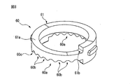
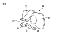
- FIG. 8 is a perspective view of the rail cam member 60
- FIG. 9 is another perspective view of the rail cam member 60.
- the rail cam member 60 is arranged so that the upper side is the rear side of the mechanical pencil 1 in FIG.
- the rail cam member 60 is a member formed in an annular shape.
- Two adjusting recesses 60a are formed symmetrically around the central axis on the front end surface of the rail cam member 60.
- Each of the adjusting recesses 60a has six first fitting recesses 60b, which are recesses of the same depth parallel to each other at equal intervals along the circumferential direction, and one second recess, which is shallower than the first fitting recess 60b. It is composed of a fitting recess 60c.
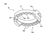
- a rail cam 61 is formed on the rear end surface of the rail cam member 60.
- the rail cam 61 has a second slope 61a, which is an annular cam surface such as a slope or a spiral, and a starting point (starting point) of the second slope 61a, which are provided on the end surface of the annular cam so as to rise along the circumferential direction. It has a second step 61b provided in the axial direction between the low position) and the final point (high position). That is, the second step 61b is configured to connect the starting point and the final point of the second slope 61a.
- the second slope 61a of the rail cam 61 has a steeper slope than the first slope 51a of the dial cam 51.
- the height of the second step 61b of the rail cam 61 is higher than the height of the first step 51b of the dial cam 51.
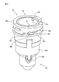
- FIG. 10 is a perspective view of the combined dial cam member 50 and the rail cam member 60
- FIG. 11 is another perspective view of the combined dial cam member 50 and the rail cam member 60.
- the dial cam member 50 and the rail cam member 60 are arranged so that the upper side is the rear side of the mechanical pencil 1 in FIGS. 10 and 11.
- the annular rail cam member 60 is combined by being inserted into the rear end portion of the small diameter portion 50b of the dial cam member 50 and locked by the flange portion 50c. That is, the front end surface of the rail cam member 60 comes into contact with the rear end surface of the flange portion 50c of the dial cam member 50.
- each of the fitting protrusions 50d provided on the flange portion 50c of the dial cam member 50 is formed in the first fitting recess 60b or the second fitting recess 60c of any of the adjusting recesses 60a of the rail cam member 60. Fit. Therefore, the rail cam member 60 is arranged on the radial outer side of the dial cam member 50.
- the fitting protrusion 50d is fitted in the first fitting recess 60b adjacent to the second fitting recess 60c. Further, in FIG. 11, the fitting protrusion 50d is fitted in the second fitting recess 60c.
- the dial cam 51 of the dial cam member 50 is arranged in the vicinity of the rail cam 61 of the rail cam member 60.
- the dial cam 51 and the rail cam 61 work together to form a series of, or annular, feeding cam surfaces 70 in the circumferential direction.
- the dial cam member 50 and the rail cam member 60 are arranged outside the tip portion 9a and the intermediate portion 9b of the slider 9 in a combined state.
- the outer peripheral surface of a part of the dial cam member 50 and the rail cam member 60 is covered with the mouth member 4.
- a coil spring 72 is arranged between the inner surface of the front end portion of the mouthpiece member 4 and the flange portion 50c of the dial cam member 50.
- the contact element 9c of the slider 9 maintains a state of being in contact with the feeding cam surface 70.
- the movement of the dial cam member 50 and the rail cam member 60 to the rear is restricted by the rear end surface of the rail cam member 60 coming into contact with the front end surface of the front shaft 2.
- the outer peripheral surface of the rail cam member 60 engages with the inner peripheral surface of the mouth member 4, and the rotation of the rail cam member 60 with respect to the mouth member 4 and the shaft cylinder 6 is restricted.
- the shape of the feeding cam surface 70 can be changed by rotating the dial cam member 50 and the rail cam member 60 relative to the central axis. That is, the user grips the axle cylinder 6 with one hand and grips the grip portion 50a of the dial cam member 50 protruding from the tip of the axle cylinder 6 with the other hand, while holding the dial cam with respect to the axle cylinder 6.
- the member 50 is rotated around the central axis. Since the rail cam member 60 is engaged with the barrel 6, the dial cam member 50 rotates about the central axis with respect to the rail cam member 60.
- the rotation of the dial cam member 50 with respect to the rail cam member 60 is such that the fitting projection 50d of the dial cam member 50 moves between the adjacent first fitting recesses 60b or the second fitting recesses 60c of the corresponding rail cam member 60 to fit. It is done step by step to match. Therefore, the rotation of the dial cam member 50 with respect to the rail cam member 60 around the central axis is performed stepwise within the range of the adjusting recess 60a of the rail cam member 60 in which the fitting projection 50d of the dial cam member 50 can move.
- the rail cam 61 of the rail cam member 60 and the dial cam of the dial cam member 50 The relative position with respect to 51 changes, and as a result, the shape of the feeding cam surface 70 can be changed.
- the dial cam member 50 is urged against the rail cam member 60 by the coil spring 72, and a click feeling is obtained when the dial cam member 50 is gradually rotated with respect to the rail cam member 60.
- the change in the shape of the feeding cam surface 70 will be further described with reference to FIGS. 12 and 13.
- FIG. 12 is a schematic view showing the pay-out cam surface 70 of FIG. 10
- FIG. 13 is a schematic view showing the pay-out cam surface 70 of FIG. 12 and 13 show a cylindrical surface around the central axis including the feeding cam surface 70 in the circumferential direction in order to show the positional relationship between the dial cam member 50 and the rail cam member 60.
- the upper side is the rear side of the mechanical pencil 1.
- the dial cam member 50 is aligned with respect to the rail cam member 60 so that the first slope 51a of the dial cam 51 and the second slope 61a of the rail cam 61 are arranged in a radial direction. ing.
- the height (height difference) of the step 71 (head) in the axial direction formed by the first slope 51a of the dial cam 51 and the second step 61b of the rail cam 61 is set to the step height H.
- the dial cam is such that the second slope 61a of the rail cam 61 is located more rearward than the first slope 51a of the dial cam 51 as compared with the feeding cam surface 70 shown in FIG.
- the member 50 is aligned with respect to the rail cam member 60. That is, in FIG. 13, as described above, the fitting protrusion 50d is fitted in the second fitting recess 60c, which is a shallow recess as compared with the first fitting recess 60b. Therefore, the rail cam 61 is arranged further behind the dial cam 51. On the other hand, when the fitting protrusion 50d moves between the six first fitting recesses 60b which are recesses of the same depth, the rail cam 61 is at the same position in the axial direction with respect to the dial cam 51.
- the step height H is the smallest when the fitting protrusion 50d is fitted in the first fitting recess 60b farthest from the second fitting recess 60c in the adjustment recess 60a.
- the step height H increases proportionally according to the inclination of the first slope 51a of the dial cam 51. That is, when the fitting protrusion 50d moves between the adjacent first fitting recesses 60b, the amount of change in the step height H is constant. From the state shown in FIG.
- the fitting protrusion 50d is fitted in the first fitting recess 60b adjacent to the second fitting recess 60c
- the fitting protrusion 50d is fitted in the second fitting recess 60c.
- the rotor 40 of the rotation drive mechanism 30 gradually rotates and drives the slider 9 based on the cushioning operation of the writing core 7. That is, when the tip portion 9a of the slider 9 is viewed first, the slider 9 rotates clockwise around the central axis. Due to this rotational movement, the abutting element 9c of the slider 9 moves in the circumferential direction in cooperation with the feeding cam surface 70. That is, the abutting element 9c of the slider 9 moves so as to rise along the first slope 51a of the dial cam 51 or the second slope 61a of the rail cam 61 constituting the feeding cam surface 70. At this time, the slider 9 gradually retracts.
- the abutment element 9c When the abutment element 9c reaches the step 71, it is pressed by the urging force of the cam abutting spring 18 and falls into the step 71. That is, the slider 9 moves further forward from the second slope 61a of the rail cam 61 by the step height H of the step 71. At this time, since the holding chuck 10 arranged inside the slider 9 also moves forward in the same manner, the writing core 7 held by the holding chuck 10 is pulled out from the ball chuck 11 and is relatively stepped from the tip pipe 8. It is fed out by the height H. Therefore, the amount of the writing core 7 to be extended, that is, the amount of extension is equal to the step height H.
- the writing core 7 can be fed out from the tip pipe 8 every time the abutting element 9c goes around along the feeding cam surface 70. By repeating this operation, the writing core 7 is sequentially drawn out while the writing core 7 is worn along with the writing operation.
- the core feeding mechanism in the core feeding mechanism, the abutting element 9c moves along the feeding cam surface 70 according to the rotation of the rotor 40, and the slider 9 advances when the abutting element 9c falls into the step 71 of the feeding cam surface 70.
- the writing core 7 held by the holding chuck 10 is pulled out from the ball chuck 11 by the operation.
- the core feeding mechanism can convert the rotational driving force of the rotor 40 in the rotary driving mechanism 30 into the feeding operation of the writing core 7.
- the configuration that forms a height difference on the feeding cam surface 70 is generically called a "head".
- the mechanical pencil 1 is configured so that the writing core 7 held by the ball chuck 11 is also rotationally driven by receiving the rotational driving force of the rotor 40 in the rotational drive mechanism 30. Therefore, it is possible to prevent the writing core 7 from being unevenly worn as the writing progresses, and as a result, it is possible to prevent a large change in the thickness of the drawn line and the density of the drawn line.
- the rotation drive mechanism 30 has a rotor 40, and receives an axial backward movement due to the writing pressure received by the writing core 7 gripped by the ball chuck 11 and an axial forward movement due to the release of the writing pressure. The rotor 40 is rotationally driven in one direction.
- the step height H of the step 71 on the feeding cam surface 70 is changed by simply rotating the dial cam member 50 and the rail cam member 60 relative to the central axis. be able to. Therefore, the feeding amount of the writing core 7 can be adjusted more easily and accurately by the core feeding mechanism.
- the writing operation can be performed.
- the amount of protrusion of the writing core 7 from the tip pipe 8 can always be kept constant.
- the dial cam 51 it is preferable to configure the dial cam 51 so that a step 71 having a step height H corresponding to a length exceeding the degree of wear of the writing core 7 which is usually assumed is formed. Thereby, the feeding amount of the writing core 7 can be set according to the preference of all users.
- the adjusting recess 60a has a second fitting recess 60c that is shallower than the first fitting recess 60b, so that the dial cam member 50 and the rail cam member 60 rotate in other predetermined rotation positions.
- the dial cam member 50 and the rail cam member 60 can be separated from each other in the axial direction as compared with the position.
- the dial cam member 50 has a fitting protrusion
- the rail cam member 60 has a plurality of fitting recesses that can be fitted with the fitting protrusion
- one of the plurality of fitting recesses is in the predetermined rotation position.
- the dial cam member 50 and the rail cam member 60 are configured to be separated from each other in the axial direction.
- the step height H of the step 71 can be adjusted extremely rather than proportionally, and the feeding amount can be extremely increased.
- the amount of wear of the writing core 7 is larger than that of the normal writing pressure. In such a case, by extremely increasing the feeding amount, writing can be continued for a long time with one knock operation. You will be able to do it.
- the dial cam member 50 is a cylindrical member as the first cam member, but it may be an annular member.
- the rail cam member 60 was an annular member as the second cam member, it may be a cylindrical member.
- a rail cam 61 may be provided on the first cam member, and a dial cam 51 may be provided on the second cam member. That is, the annular or tubular first cam member and the annular or tubular second cam member arranged on the radial outer side of the first cam member cooperate to form the feeding cam surface. May be good.
- the step height of the step may be adjusted by moving the first cam member and the second cam member relatively back and forth, that is, by separating them in the axial direction.
- the writing operation is performed in a state where the mechanical pencil is tilted from the state perpendicular to the writing surface.
- the retreat operation in the axial direction due to the writing pressure is performed by the axial component of the force due to the writing pressure applied perpendicularly to the writing surface by the mechanical pencil in an inclined state.
- the component force in the direction perpendicular to the axial direction of the force due to the writing pressure increases the resistance during rotation of the rotating member that rotates relative to the barrel.
- the outer surface of the rotating member constitutes a part of the barrel, for example, by sliding contact with the mouth member, the rotation of the rotating member by the rotation drive mechanism is supported, but the above-mentioned component force in the vertical direction is frictional.
- Increases dynamic resistance that is, frictional resistance. If the frictional resistance is large, a user having a particularly small writing pressure may not be able to rotate the rotation drive mechanism.
- the moment of force due to frictional resistance also increases.
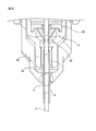
- FIG. 14 is an enlarged cross-sectional view of the front end portion of the mechanical pencil 1 of FIG.
- the rear end of the cam contact spring 18 is attached to the flange portion 12a of the relay member 12, and the front end of the cam contact spring 18 is the slider 9. It is attached to the inner wall of the rear end.
- the relay member 12 connected to the rotor 40 transmits the rotational driving force of the rotor 40 in the rotary drive mechanism 30 to the ball chuck 11 in a state where the writing core 7 is gripped, but to the slider 9. Do not communicate directly. That is, although the slider 9 is arranged outside the front end portion of the relay member 12, it is not directly connected to the relay member 12.
- the rotational driving force in the rotational drive mechanism 30 is transmitted from the rotor 40 to the slider 9 via the cam contact spring 18.
- the cam contact spring 18 functions to bring the contact element 9c into contact with the cam surface by urging the slider 9 forward, and also functions as a torsion spring (torsion spring).
- the slider 9, the writing core 7, the ball chuck 11, and the tip pipe 8 attached to the slider 9 rotate under the rotational driving force of the rotor 40 in the rotational driving mechanism 30. Therefore, these members including the tip pipe 8 constitute a rotating member that rotates with respect to the barrel 6.
- the rotation of the rotating member is supported by the tip pipe 8 sliding in contact with the barrel 6, specifically the dial cam member 50, in the portion C of FIG. Since the outer diameter of the tip pipe 8 is slightly larger than the outer diameter of the writing core 7, it is very thin as compared with other members of the rotating member. Therefore, the moment of force due to frictional resistance becomes smaller.
- the contact area between the outer surface of the tip pipe 8 and the inner surface of the dial cam member 50 can be reduced, and the frictional resistance during rotation of the rotating member by the rotation driving mechanism 30 can be further reduced. As a result, even a user with a small writing pressure can rotate the rotation drive mechanism 30 with the mechanical pencil 1.
- the tip pipe 8 is preferably a cylindrical member made of metal.
- the member on the shaft cylinder 6 side that is, the dial cam member 50 is a member made of hard plastic such as ABS and polycarbonate. Therefore, the frictional resistance is smaller in the case where the hard plastic shaft cylinder and the metal cylindrical member are in sliding contact than in the case where the hard plastic shaft cylinder and the hard plastic rotating member are in sliding contact. As a result, according to the mechanical pencil 1, the frictional resistance during rotation of the rotating member by the rotation driving mechanism 30 can be further reduced.
- the metal tip pipe 8 is manufactured by drawing, the dimensional accuracy is also good.
- the dimensional tolerance is ⁇ 0.02 mm, whereas in the case of a metal part, the dimensional tolerance can be ⁇ 0.01 m. Therefore, the clearance between the tip pipe 8 and the dial cam member 50 can be made smaller, and the rattling of the rotating member during rotation can be reduced.
- the cylindrical member can be arbitrarily configured as long as the sliding contact between the shaft cylinder and the rotating member is performed by the metal cylindrical member.
- the metal cylindrical member may be arranged not on the tip pipe 8 but on the outer surface of the slider 9 near the tip pipe, for example, the outer surface of the tip portion 9a.
- the metal cylindrical member may be arranged not on the rotating member side but on a portion that is in sliding contact with the rotating member on the barrel side, for example, the inner surface of the dial cam member 50.
- the sharp pencil 1 includes a metal cylindrical member provided on one of the axle cylinder and the rotating member, and the rotating member rotates by receiving the rotational driving force of the rotor.
- the writing core held by the ball chuck is configured to rotate, and the other side of the barrel and the rotating member is in sliding contact with the surface of the cylindrical member, so that the rotation of the rotating member by the rotation driving mechanism is supported.
- the knock cover is removed when the eraser is used. Further, when replenishing the writing core, the knock cover and the eraser are removed from the knock member.
- the knock cover is a very small part that can slip off your hand when removed from the knock member and the knock cover can be lost. Further, even if the knock cover is placed on a desk or the like, since it generally has a cylindrical outer shape, it may roll off from the desk or the like and the knock cover may be lost.
- FIG. 15 is a perspective view of the knock cover 23
- FIG. 16 is a perspective view of the knock cover 23 attached to the rear end portion of the mechanical pencil 1
- FIG. 17 is a perspective view of the knock cover 23 attached to the mechanical pencil 1. It is a perspective view of the state attached to the front end part.
- the knock cover 23 is formed with an opening end 23a. By inserting the rear end portion of the knock rod 20 into the opening end 23a, the knock cover 23 can be fitted to the outer peripheral surface of the knock rod 20. At the opening end 23a of the knock cover 23, that is, at the opening end surface, two notches 23b are formed symmetrically around the central axis. In the knock cover 23, a through hole 23c (FIG. 3) is formed at a closed end opposite to the opening end 23a. Since the through hole 23c is formed, even if the knock cover 23 is accidentally swallowed by an infant or the like, safety can be ensured without obstructing the airway.
- the dial cam member 50 which is the front end portion of the barrel 6, is provided with two locking projections 50e.
- the knock cover 23 can be fitted to the front end portion of the barrel 6. That is, the notch 23b of the knock cover 23 fits into the locking projection 50e of the barrel 6, so that the knock cover 23 is detachably fitted to the front end of the barrel 6.
- the knock cover 23 can be fitted to either the front end portion or the rear end portion of the barrel 6. Therefore, at the time of writing, the knock cover 23 is prevented from being lost by fitting the knock cover 23 to the rear end portion of the barrel 6. On the other hand, the knock cover 23 is prevented from being lost by fitting the knock cover 23 to the front end portion of the barrel 6 at the time of non-writing such as storage or storage, or at the time of replenishment of the writing core.
- the dial cam member 50 can be more easily rotated with respect to the shaft cylinder 6 by gripping the knock cover 23 fitted to the dial cam member 50. That is, by fitting the knock cover 23, the length of the grip portion 50a of the dial cam member 50 in the axial direction becomes substantially longer, and it becomes easier to grip, so that it becomes easier to apply a rotational force.
- the knock cover 23 may be fitted to any member, for example, a mouth member, as long as it can be fitted to the front end portion of the barrel. .. That is, the knock cover 23 may be fitted to any member as long as it can be fitted to the rear end of the barrel and to the front end of the barrel. Further, in the above-described embodiment, the two locking protrusions are fitted to the two notches, but they may be fitted in other numbers or shapes.
- the material of the holding chuck is generally a rubber material such as nitrile rubber. Therefore, the holding chuck may creep and deform over time, and the holding force may decrease. Further, the writing core has a dimensional variation in the range of 0.55 mm to 0.58 mm in the case of a product having a display diameter of 0.5 mm, for example. Therefore, due to variations in the dimensions during rubber molding, the holding force may become stronger or weaker in relation to the variations in the dimensions of the writing core.
- FIG. 18 is a perspective view of the first holding chuck 80
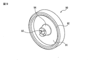
- FIG. 19 is a perspective view of the second holding chuck 90
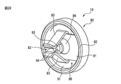
- FIG. 20 is a perspective view of the holding chuck 10.
- the holding chuck 10 has a first holding chuck 80 and a second holding chuck 90.
- the first holding chuck 80 is a metal plate-shaped member and is formed by press working.
- the first holding chuck 80 has a substantially rectangular rectangular plate portion 81 and a first holding portion 82.
- the first holding portion 82 includes a plate-shaped portion 83 which is two plate-shaped members extending from the central portion of each long side of the rectangular plate portion 81.
- Each of the plate-shaped portions 83 is bent and extended so as to be close to each other from the long side of the rectangular plate portion 81, and is bent and extended in the opposite direction so as to be separated from each other at the bent portion 84.
- a first insertion hole 85 which is a circular through hole, is formed at the center of the rectangular plate portion 81.
- the short side of the rectangular plate portion 81 is formed in an arc shape. As will be described later, the writing core 7 can be held by the first holding portion 82.
- the second holding chuck 90 is a disc-shaped member made of non-metal, for example, rubber or resin.
- the second holding chuck 90 defines a disk portion 91, a peripheral wall 92 provided along the outer peripheral edge of one surface of the disk portion 91, and a second insertion hole 93 at the center of the disk portion 91. Moreover, it has a second holding portion 94 protruding from the disc portion 91.
- the second holding portion 94 has a conical trapezoidal outer shape. Therefore, the second holding portion 94 has a tapered outer peripheral surface, and can hold the writing core 7 in the narrowed tip opening.
- the holding force of the writing core 7 by the second holding portion 94 of the second holding chuck 90 is set to be smaller than the holding force of the writing core 7 by the first holding portion 82 of the first holding chuck 80.
- the first holding chuck 80 is attached to the second holding chuck 90. Specifically, each of the short sides of the rectangular plate portion 81 of the first holding chuck 80 made of metal engages with the peripheral wall 92 of the second holding chuck 90. At this time, the second holding portion 94 of the second holding chuck 90 is inserted into the first insertion hole 85 of the first holding chuck 80.
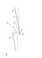
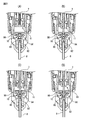
- FIG. 21 is a diagram illustrating the operation of the holding chuck 10.
- FIG. 21A shows a state immediately after the writing core 7 is put in the core case 19. At this time, the ball chuck 11 has not yet gripped the writing core 7.
- the knock operation is performed in this state, the writing core 7 moves forward due to gravity, and the ball chuck 11 grips the writing core 7 (FIG. 21 (B)).
- the knock operation is further performed, the writing core 7 advances and is inserted into the second insertion hole 93 of the second holding chuck 90, and is held by the second holding portion 94. Therefore, even if the pressing by the knock operation is released, the writing core 7 is held by the second holding chuck 90 without retracting (FIG. 21 (C)).
- the ball chuck 11 advances while gripping the writing core 7, and the writing core 7 is held by the first holding portion 82 of the first holding chuck 80 (FIG. 21 (D)). Specifically, as the writing core 7 advances, it is inserted between the two plate-shaped portions 83 of the first holding portion 82. At this time, the writing core 7 is sandwiched by the elastic deformation of the first holding portion 82, specifically, the two plate-shaped portions 83 by the elastic deformation. At the same time, the writing core 7 is also held by the second holding portion 94 of the second holding chuck 90. Next, when the pressing by the knock operation is released, only the ball chuck 11 retracts while the writing core 7 is held by the first holding chuck 80 and the second holding chuck 90. Then, by repeating the knock operation, the writing core 7 can be sequentially delivered by a predetermined amount in conjunction with the back-and-forth movement of the ball chuck 11 described above.
- the mechanical pencil 1 is a first holding chuck 80 having a first holding portion 82 made of metal as a holding chuck 10, and writing is performed by holding the writing core 7 by elastic deformation of the first holding portion 82.
- the core 7 can be held.
- the first holding chuck 80 made of metal it is possible to realize a holding chuck having less decrease in holding force due to aging and high dimensional accuracy as compared with the conventional holding chuck.
- the first holding chuck 80 and the second holding chuck 90 are integrally arranged in the barrel 6, but the first holding chuck 80 and the second holding chuck 90 are separated from each other. It may be arranged. Further, in the above-described embodiment, the second holding chuck 90 is arranged behind the first holding chuck 80 in the barrel 6, but the second holding chuck 90 is integrated in front of the first holding chuck 80. It may be arranged as a target or separated.
- the holding force of the writing core 7 by the second holding portion 94 of the second holding chuck 90 is set to be smaller than the holding force of the writing core 7 by the first holding portion 82 of the first holding chuck 80. .. Therefore, the second holding chuck 90 serves as an auxiliary holding chuck that assists the first holding chuck 80.
- the holding force of the writing core 7 of the second holding chuck 90 may be lower than the holding force of the conventional holding chuck.
- the holding chuck 10 has the first holding chuck 80 and the second holding chuck 90, but the holding chuck 10 may have only the first holding chuck 80.
- a case where the holding chuck 10 has only the first holding chuck 80 will be described with reference to FIG. 22.
- FIG. 22 is a diagram illustrating the operation of the first holding chuck 80.
- FIG. 22A shows a state in which the writing core 7 is put in the core case 19 and a knock operation is performed.
- the writing core 7 passes through the first insertion hole 85 and is arranged in front of the first holding portion 82.
- a knock operation is further performed in this state, the writing core 7 moves forward and is held by the first holding portion 82 (FIG. 22 (B)). Then, by repeating the knock operation, the writing core 7 can be sequentially delivered by a predetermined amount in conjunction with the back-and-forth movement of the ball chuck 11 described above.
- the holding chuck 10 has the first holding chuck 80 provided with the first holding portion 82 made of metal, so that the holding chuck 10 is held over time as compared with the conventional holding chuck made of rubber material. It is possible to obtain a holding chuck with little decrease in force and high dimensional accuracy. Further, since the portion of the first holding portion 82 that comes into contact with the writing core 7, that is, the bent portion 84 is formed in a curved shape, the writing core 7 is not damaged.
- the first holding chuck having the first metal holding portion can hold the writing core by holding the writing core by elastic deformation of the first holding portion
- the first holding chuck can be arbitrarily used.
- the first holding portion is composed of two plate-shaped members, but may be composed of three or more plate-shaped members.
- the first holding portion may be formed of a rod-shaped member capable of holding the writing core 7 instead of the plate-shaped member.
Landscapes
- Mechanical Pencils And Projecting And Retracting Systems Therefor, And Multi-System Writing Instruments (AREA)
Applications Claiming Priority (2)
| Application Number | Priority Date | Filing Date | Title |
|---|---|---|---|
| JP2019-086697 | 2019-04-26 | ||
| JP2019086697A JP2020183043A (ja) | 2019-04-26 | 2019-04-26 | シャープペンシル |
Publications (1)
| Publication Number | Publication Date |
|---|---|
| WO2020218440A1 true WO2020218440A1 (ja) | 2020-10-29 |
Family
ID=72942039
Family Applications (1)
| Application Number | Title | Priority Date | Filing Date |
|---|---|---|---|
| PCT/JP2020/017541 Ceased WO2020218440A1 (ja) | 2019-04-26 | 2020-04-23 | シャープペンシル |
Country Status (3)
| Country | Link |
|---|---|
| JP (1) | JP2020183043A (enExample) |
| TW (1) | TW202103977A (enExample) |
| WO (1) | WO2020218440A1 (enExample) |
Cited By (1)
| Publication number | Priority date | Publication date | Assignee | Title |
|---|---|---|---|---|
| WO2022092293A1 (ja) * | 2020-11-02 | 2022-05-05 | 三菱鉛筆株式会社 | シャープペンシル |
Citations (3)
| Publication number | Priority date | Publication date | Assignee | Title |
|---|---|---|---|---|
| JPS54144222A (en) * | 1978-04-28 | 1979-11-10 | Iwasaki Kosei | Pusheddout writing implement |
| JPS56154506U (enExample) * | 1980-04-21 | 1981-11-18 | ||
| US6116799A (en) * | 1998-11-19 | 2000-09-12 | Kotobuki & Co., Ltd. | Installation structure of lead advancing mechanism in writing instrument |
Family Cites Families (1)
| Publication number | Priority date | Publication date | Assignee | Title |
|---|---|---|---|---|
| JPS56108575U (enExample) * | 1980-01-19 | 1981-08-22 |
-
2019
- 2019-04-26 JP JP2019086697A patent/JP2020183043A/ja active Pending
-
2020
- 2020-04-23 WO PCT/JP2020/017541 patent/WO2020218440A1/ja not_active Ceased
- 2020-04-24 TW TW109113781A patent/TW202103977A/zh unknown
Patent Citations (3)
| Publication number | Priority date | Publication date | Assignee | Title |
|---|---|---|---|---|
| JPS54144222A (en) * | 1978-04-28 | 1979-11-10 | Iwasaki Kosei | Pusheddout writing implement |
| JPS56154506U (enExample) * | 1980-04-21 | 1981-11-18 | ||
| US6116799A (en) * | 1998-11-19 | 2000-09-12 | Kotobuki & Co., Ltd. | Installation structure of lead advancing mechanism in writing instrument |
Cited By (3)
| Publication number | Priority date | Publication date | Assignee | Title |
|---|---|---|---|---|
| WO2022092293A1 (ja) * | 2020-11-02 | 2022-05-05 | 三菱鉛筆株式会社 | シャープペンシル |
| CN116507505A (zh) * | 2020-11-02 | 2023-07-28 | 三菱铅笔株式会社 | 自动铅笔 |
| JP7621089B2 (ja) | 2020-11-02 | 2025-01-24 | 三菱鉛筆株式会社 | シャープペンシル |
Also Published As
| Publication number | Publication date |
|---|---|
| JP2020183043A (ja) | 2020-11-12 |
| TW202103977A (zh) | 2021-02-01 |
Similar Documents
| Publication | Publication Date | Title |
|---|---|---|
| JP6275195B2 (ja) | シャープペンシル | |
| WO2020217682A1 (ja) | シャープペンシル | |
| WO2020218440A1 (ja) | シャープペンシル | |
| WO2020218260A1 (ja) | シャープペンシル | |
| JP2020183040A (ja) | シャープペンシル | |
| JP7204467B2 (ja) | シャープペンシル | |
| JP7740924B2 (ja) | シャープペンシル | |
| JP7736474B2 (ja) | シャープペンシル | |
| JP7736475B2 (ja) | 筆記具 | |
| JP6807719B2 (ja) | シャープペンシル | |
| JP6491829B2 (ja) | シャープペンシル | |
| WO2023002878A1 (ja) | シャープペンシル | |
| JP5933960B2 (ja) | ノック式筆記具 | |
| CN119546465A (zh) | 自动铅笔 |
Legal Events
| Date | Code | Title | Description |
|---|---|---|---|
| 121 | Ep: the epo has been informed by wipo that ep was designated in this application |
Ref document number: 20794436 Country of ref document: EP Kind code of ref document: A1 |
|
| NENP | Non-entry into the national phase |
Ref country code: DE |
|
| 122 | Ep: pct application non-entry in european phase |
Ref document number: 20794436 Country of ref document: EP Kind code of ref document: A1 |