WO2020218182A1 - 情報処理装置およびデバイス情報導出方法 - Google Patents
情報処理装置およびデバイス情報導出方法 Download PDFInfo
- Publication number
- WO2020218182A1 WO2020218182A1 PCT/JP2020/016854 JP2020016854W WO2020218182A1 WO 2020218182 A1 WO2020218182 A1 WO 2020218182A1 JP 2020016854 W JP2020016854 W JP 2020016854W WO 2020218182 A1 WO2020218182 A1 WO 2020218182A1
- Authority
- WO
- WIPO (PCT)
- Prior art keywords
- information
- marker
- marker image
- input device
- unit
- Prior art date
- Legal status (The legal status is an assumption and is not a legal conclusion. Google has not performed a legal analysis and makes no representation as to the accuracy of the status listed.)
- Ceased
Links
Images


Classifications
-
- A—HUMAN NECESSITIES
- A63—SPORTS; GAMES; AMUSEMENTS
- A63F—CARD, BOARD, OR ROULETTE GAMES; INDOOR GAMES USING SMALL MOVING PLAYING BODIES; VIDEO GAMES; GAMES NOT OTHERWISE PROVIDED FOR
- A63F13/00—Video games, i.e. games using an electronically generated display having two or more dimensions
- A63F13/20—Input arrangements for video game devices
- A63F13/21—Input arrangements for video game devices characterised by their sensors, purposes or types
- A63F13/213—Input arrangements for video game devices characterised by their sensors, purposes or types comprising photodetecting means, e.g. cameras, photodiodes or infrared cells
-
- G—PHYSICS
- G02—OPTICS
- G02B—OPTICAL ELEMENTS, SYSTEMS OR APPARATUS
- G02B27/00—Optical systems or apparatus not provided for by any of the groups G02B1/00 - G02B26/00, G02B30/00
- G02B27/01—Head-up displays
- G02B27/017—Head mounted
- G02B27/0172—Head mounted characterised by optical features
-
- A—HUMAN NECESSITIES
- A63—SPORTS; GAMES; AMUSEMENTS
- A63F—CARD, BOARD, OR ROULETTE GAMES; INDOOR GAMES USING SMALL MOVING PLAYING BODIES; VIDEO GAMES; GAMES NOT OTHERWISE PROVIDED FOR
- A63F13/00—Video games, i.e. games using an electronically generated display having two or more dimensions
- A63F13/20—Input arrangements for video game devices
- A63F13/21—Input arrangements for video game devices characterised by their sensors, purposes or types
- A63F13/211—Input arrangements for video game devices characterised by their sensors, purposes or types using inertial sensors, e.g. accelerometers or gyroscopes
-
- A—HUMAN NECESSITIES
- A63—SPORTS; GAMES; AMUSEMENTS
- A63F—CARD, BOARD, OR ROULETTE GAMES; INDOOR GAMES USING SMALL MOVING PLAYING BODIES; VIDEO GAMES; GAMES NOT OTHERWISE PROVIDED FOR
- A63F13/00—Video games, i.e. games using an electronically generated display having two or more dimensions
- A63F13/20—Input arrangements for video game devices
- A63F13/21—Input arrangements for video game devices characterised by their sensors, purposes or types
- A63F13/212—Input arrangements for video game devices characterised by their sensors, purposes or types using sensors worn by the player, e.g. for measuring heart beat or leg activity
-
- A—HUMAN NECESSITIES
- A63—SPORTS; GAMES; AMUSEMENTS
- A63F—CARD, BOARD, OR ROULETTE GAMES; INDOOR GAMES USING SMALL MOVING PLAYING BODIES; VIDEO GAMES; GAMES NOT OTHERWISE PROVIDED FOR
- A63F13/00—Video games, i.e. games using an electronically generated display having two or more dimensions
- A63F13/25—Output arrangements for video game devices
-
- A—HUMAN NECESSITIES
- A63—SPORTS; GAMES; AMUSEMENTS
- A63F—CARD, BOARD, OR ROULETTE GAMES; INDOOR GAMES USING SMALL MOVING PLAYING BODIES; VIDEO GAMES; GAMES NOT OTHERWISE PROVIDED FOR
- A63F13/00—Video games, i.e. games using an electronically generated display having two or more dimensions
- A63F13/40—Processing input control signals of video game devices, e.g. signals generated by the player or derived from the environment
- A63F13/42—Processing input control signals of video game devices, e.g. signals generated by the player or derived from the environment by mapping the input signals into game commands, e.g. mapping the displacement of a stylus on a touch screen to the steering angle of a virtual vehicle
- A63F13/428—Processing input control signals of video game devices, e.g. signals generated by the player or derived from the environment by mapping the input signals into game commands, e.g. mapping the displacement of a stylus on a touch screen to the steering angle of a virtual vehicle involving motion or position input signals, e.g. signals representing the rotation of an input controller or a player's arm motions sensed by accelerometers or gyroscopes
-
- A—HUMAN NECESSITIES
- A63—SPORTS; GAMES; AMUSEMENTS
- A63F—CARD, BOARD, OR ROULETTE GAMES; INDOOR GAMES USING SMALL MOVING PLAYING BODIES; VIDEO GAMES; GAMES NOT OTHERWISE PROVIDED FOR
- A63F13/00—Video games, i.e. games using an electronically generated display having two or more dimensions
- A63F13/50—Controlling the output signals based on the game progress
- A63F13/52—Controlling the output signals based on the game progress involving aspects of the displayed game scene
- A63F13/525—Changing parameters of virtual cameras
- A63F13/5255—Changing parameters of virtual cameras according to dedicated instructions from a player, e.g. using a secondary joystick to rotate the camera around a player's character
-
- G—PHYSICS
- G06—COMPUTING OR CALCULATING; COUNTING
- G06F—ELECTRIC DIGITAL DATA PROCESSING
- G06F3/00—Input arrangements for transferring data to be processed into a form capable of being handled by the computer; Output arrangements for transferring data from processing unit to output unit, e.g. interface arrangements
- G06F3/01—Input arrangements or combined input and output arrangements for interaction between user and computer
- G06F3/017—Gesture based interaction, e.g. based on a set of recognized hand gestures
-
- G—PHYSICS
- G06—COMPUTING OR CALCULATING; COUNTING
- G06F—ELECTRIC DIGITAL DATA PROCESSING
- G06F3/00—Input arrangements for transferring data to be processed into a form capable of being handled by the computer; Output arrangements for transferring data from processing unit to output unit, e.g. interface arrangements
- G06F3/01—Input arrangements or combined input and output arrangements for interaction between user and computer
- G06F3/03—Arrangements for converting the position or the displacement of a member into a coded form
- G06F3/0304—Detection arrangements using opto-electronic means
-
- G—PHYSICS
- G06—COMPUTING OR CALCULATING; COUNTING
- G06F—ELECTRIC DIGITAL DATA PROCESSING
- G06F3/00—Input arrangements for transferring data to be processed into a form capable of being handled by the computer; Output arrangements for transferring data from processing unit to output unit, e.g. interface arrangements
- G06F3/01—Input arrangements or combined input and output arrangements for interaction between user and computer
- G06F3/03—Arrangements for converting the position or the displacement of a member into a coded form
- G06F3/033—Pointing devices displaced or positioned by the user, e.g. mice, trackballs, pens or joysticks; Accessories therefor
- G06F3/0346—Pointing devices displaced or positioned by the user, e.g. mice, trackballs, pens or joysticks; Accessories therefor with detection of the device orientation or free movement in a three-dimensional [3D] space, e.g. 3D mice, 6-DOF [six degrees of freedom] pointers using gyroscopes, accelerometers or tilt-sensors
-
- G—PHYSICS
- G02—OPTICS
- G02B—OPTICAL ELEMENTS, SYSTEMS OR APPARATUS
- G02B27/00—Optical systems or apparatus not provided for by any of the groups G02B1/00 - G02B26/00, G02B30/00
- G02B27/01—Head-up displays
- G02B27/0101—Head-up displays characterised by optical features
- G02B2027/0138—Head-up displays characterised by optical features comprising image capture systems, e.g. camera
-
- G—PHYSICS
- G02—OPTICS
- G02B—OPTICAL ELEMENTS, SYSTEMS OR APPARATUS
- G02B27/00—Optical systems or apparatus not provided for by any of the groups G02B1/00 - G02B26/00, G02B30/00
- G02B27/0093—Optical systems or apparatus not provided for by any of the groups G02B1/00 - G02B26/00, G02B30/00 with means for monitoring data relating to the user, e.g. head-tracking, eye-tracking
Definitions
- the present invention relates to a technique for deriving position information and posture information of a device.
- Patent Document 1 acquires a frame image of the front of a game device, estimates the position information and attitude information of the game controller in real space from the position of the LED image of the game controller in the frame image, and estimates the position information and the position information. / Or disclose a game device that reflects attitude information in the processing of a game application.
- the information processing device links the movements of the player character and the game object in the game space with changes in the position and posture of the device to be tracked, thereby realizing intuitive operation by the user.
- a plurality of lit markers are attached to the device in order to estimate the position and orientation of the device.
- the information processing device identifies the coordinates of a plurality of marker images included in the captured image of the device, and compares the coordinates with the three-dimensional coordinates of the plurality of markers in the three-dimensional model of the device to obtain the position of the device and the position of the device in the real space. Estimate the posture.
- the captured image contains marker images of a plurality of devices, the number of marker images in the captured image increases according to the number of devices, so that the amount of calculation of the estimation process increases.
- an object of the present invention is to provide a technique for reducing the amount of calculation required for estimating the position and orientation of a plurality of devices.
- the device may be an input device having an operation button, but may be simply a device to be tracked without an operation member.
- the information processing apparatus includes a captured image acquisition unit that acquires images captured by a first device having a plurality of markers and a second device having a plurality of markers. It is provided with an estimation processing unit that estimates the position information and attitude information of the first device and the position information and attitude information of the second device based on the marker image coordinates in the captured image. The estimation processing unit derives the position information and attitude information of the first device, and then derives the position information and attitude information of the second device based on the remaining marker image coordinates excluding the marker image coordinates of the first device. ..
- Another aspect of the device information derivation method of the present invention is based on a step of acquiring an image of a first device having a plurality of markers and a second device having a plurality of markers, and a marker image coordinate in the captured image.
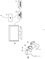
- FIG. 1 shows a configuration example of the information processing system 1 in the embodiment.
- the information processing system 1 includes an information processing device 10, a recording device 11, a head-mounted display (HMD) 100, an input device 16 operated by a user's fingers, and an output device 15 that outputs images and sounds.
- the output device 15 may be a television.
- the information processing device 10 is connected to an external network 2 such as the Internet via an access point (AP) 17.
- the AP 17 has the functions of a wireless access point and a router, and the information processing device 10 may be connected to the AP 17 by a cable or by a known wireless communication protocol.
- the recording device 11 records applications such as system software and game software.
- the information processing device 10 may download the game software from the content server to the recording device 11 via the network 2.
- the information processing device 10 executes game software and supplies image data and audio data of the game to the HMD 100.
- the information processing device 10 and the HMD 100 may be connected by a known wireless communication protocol, or may be connected by a cable.
- the HMD100 is a display device that displays an image on a display panel located in front of the user when the user wears it on the head.
- the HMD 100 separately displays an image for the left eye on the display panel for the left eye and an image for the right eye on the display panel for the right eye. These images constitute parallax images viewed from the left and right viewpoints, and realize stereoscopic vision. Since the user sees the display panel through the optical lens, the information processing device 10 supplies the parallax image data corrected for the optical distortion caused by the lens to the HMD 100.
- the output device 15 is not necessary for the user wearing the HMD 100, but by preparing the output device 15, another user can see the display image of the output device 15.
- the information processing device 10 may display the same image as the image viewed by the user wearing the HMD 100 on the output device 15, but may display another image. For example, when a user wearing an HMD and another user play a game together, the output device 15 may display a game image from the character viewpoint of the other user.
- the information processing device 10 and the input device 16 may be connected by a known wireless communication protocol, or may be connected by a cable.
- the input device 16 includes a plurality of operation members such as operation buttons, and the user operates the operation members with his / her fingers while grasping the input device 16.
- the input device 16 is used as a game controller.
- the input device 16 includes an attitude sensor including a 3-axis acceleration sensor and a 3-axis gyro sensor, and transmits sensor data to the information processing device 10 at a predetermined cycle (for example, 1600 Hz).
- the operation information of the operation member of the input device 16 are treated as operation information and reflected in the movement of the player character in the virtual three-dimensional space.
- the operation information of the operation member may be used as information for moving the player character
- the operation information such as the position, posture, and movement of the input device 16 may be used as information for moving the arm of the player character.
- the movement of the input device 16 is reflected in the movement of the player character holding the weapon, so that the user's intuitive operation is realized and the immersive feeling in the game is enhanced.
- the input device 16 In order to track the position and orientation of the input device 16, the input device 16 is provided with a plurality of markers (light emitting units) that can be photographed by the image pickup device 14 mounted on the HMD 100.
- the information processing device 10 analyzes the image taken by the input device 16 to estimate the position information and the posture information of the input device 16 in the real space, and provides the estimated position information and the posture information to the game.
- the HMD 100 is equipped with a plurality of imaging devices 14.
- the plurality of imaging devices 14 are attached to different positions on the front surface of the HMD 100 in different postures so that the entire imaging range obtained by adding the respective imaging ranges includes the entire field of view of the user.
- the image pickup device 14 may be an image sensor capable of acquiring images of a plurality of markers of the input device 16.
- the imaging device 14 has a visible light sensor used in a general digital video camera such as a CCD (Charge Coupled Device) sensor or a CMOS (Complementary Metal Oxide Semiconductor) sensor.
- the imaging device 14 has an invisible light sensor.
- the plurality of image pickup devices 14 photograph the front of the user at a predetermined cycle (for example, 60 frames / second) at synchronized timings, and transmit the image data obtained by photographing the input device 16 to the information processing device 10.
- the information processing device 10 specifies the positions of a plurality of marker images of the input device 16 included in the captured image. Although one input device 16 may be imaged by a plurality of image pickup devices 14 at the same timing, since the mounting position and mounting posture of the image pickup device 14 are known, the information processing device 10 synthesizes a plurality of captured images. Then, the position of the marker image is specified.
- the three-dimensional shape of the input device 16 and the position coordinates of the plurality of markers arranged on the surface thereof are known, and the information processing device 10 has the position coordinates of the input device 16 based on the distribution of the marker images in the captured image. And estimate the posture.
- the position coordinates of the input device 16 may be position coordinates in a three-dimensional space with the reference position as the origin, and the reference position may be position coordinates (latitude, longitude) set before the start of the game.
- the information processing device 10 can also estimate the position coordinates and the posture of the input device 16 by using the sensor data detected by the posture sensor of the input device 16. Therefore, the information processing device 10 of the embodiment may perform the tracking process of the input device 16 with high accuracy by using the estimation result based on the captured image captured by the image pickup device 14 and the estimation result based on the sensor data.
- FIG. 2 shows an example of the appearance shape of the HMD100.
- the HMD 100 is composed of an output mechanism unit 102 and a mounting mechanism unit 104.
- the mounting mechanism unit 104 includes a mounting band 106 that goes around the head and fixes the HMD 100 to the head when the user wears it.
- the wearing band 106 has a material or structure whose length can be adjusted according to the user's head circumference.
- the output mechanism 102 includes a housing 108 having a shape that covers the left and right eyes when the HMD 100 is worn by the user, and internally includes a display panel that faces the eyes when worn.
- the display panel may be a liquid crystal panel, an organic EL panel, or the like.
- Inside the housing 108 a pair of left and right optical lenses, which are located between the display panel and the user's eyes and expand the viewing angle of the user, are further provided.
- the HMD 100 may further include a speaker or earphone at a position corresponding to the user's ear, and may be configured to be connected to external headphones.
- a plurality of image pickup devices 14a, 14b, 14c, 14d are provided on the front outer surface of the housing 108.
- the image pickup device 14a is attached to the upper right corner of the front outer surface so that the camera optical axis faces diagonally upward to the right
- the image pickup device 14b is mounted so that the camera optical axis points diagonally upward to the left with reference to the user's line of sight.
- Attached to the upper left corner of the front outer surface the image pickup device 14c is attached to the lower right corner of the front side outer surface so that the camera optical axis faces diagonally downward to the right
- the image pickup device 14d is attached to the camera optical axis to face diagonally downward to the left. It is attached to the lower left corner of the front outer surface.
- the HMD 100 transmits the sensor data detected by the attitude sensor and the image data captured by the imaging device 14 to the information processing device 10, and also receives the game image data and the game audio data generated by the information processing device 10.
- FIG. 3 shows a functional block of HMD100.
- the control unit 120 is a main processor that processes and outputs various data such as image data, audio data, and sensor data, as well as instructions.
- the storage unit 122 temporarily stores data, instructions, and the like processed by the control unit 120.
- the attitude sensor 124 acquires sensor data regarding the movement of the HMD 100.
- the attitude sensor 124 includes at least a 3-axis acceleration sensor and a 3-axis gyro sensor.
- the posture sensor 124 detects the value (sensor data) of each axis component at a predetermined cycle (for example, 1600 Hz).
- the communication control unit 128 transmits the data output from the control unit 120 to the external information processing device 10 via a network adapter or an antenna by wired or wireless communication. Further, the communication control unit 128 receives data from the information processing device 10 and outputs the data to the control unit 120.
- control unit 120 When the control unit 120 receives the game image data and the game audio data from the information processing device 10, the control unit 120 supplies the game image data and the game audio data to the display panel 130 for display, and supplies the game image data and the game audio data to the audio output unit 132 for audio output.
- the display panel 130 is composed of a left-eye display panel 130a and a right-eye display panel 130b, and a pair of parallax images are displayed on each display panel.
- the control unit 120 causes the communication control unit 128 to transmit the sensor data from the attitude sensor 124, the voice data from the microphone 126, and the captured image data from the image pickup device 14 to the information processing device 10.
- FIG. 4 shows the external shape of the input device 16.
- FIG. 4A shows the front shape of the input device 16, and
- FIG. 4B shows the back shape of the input device 16.
- the input device 16 includes a case body 20, a plurality of operating members 22a, 22b, 22c, 22d (hereinafter, referred to as “operating member 22" unless otherwise specified) operated by the user, and light outside the case body 20.
- a plurality of markers 30a to 30t (hereinafter, referred to as “marker 30” when not particularly distinguished) are provided.
- the operation member 22 is arranged on the head of the case body 20, and includes an analog stick for tilting operation, a push-type button, a trigger button for inputting a pull amount, and the like.
- the case body 20 has a grip portion 21 and a curved portion 23 that connects the case body head and the case body bottom, and the user passes a finger from the index finger to the little finger between the grip portion 21 and the curved portion 23.
- the grip portion 21 is gripped.
- the user operates the operating members 22a, 22b, and 22c with the thumb and the operating member 22d with the index finger while gripping the grip portion 21.
- the markers 30h, 30i, and 30j are provided on the grip portion 21, but are arranged at positions that are not hidden by the hand even when the user grips the grip portion 21.
- the marker 30 is a light emitting portion that emits light to the outside of the case body 20, and includes a resin portion that diffuses and emits light from a light source such as an LED (Light Emitting Diode) element on the surface of the case body 20. ..
- the marker 30 is photographed by the imaging device 14 and used for estimating the position and orientation of the input device 16. Since the image pickup device 14 shoots the input device 16 at a predetermined cycle (for example, 60 frames / second), the marker 30 emits light in synchronization with the periodic shooting timing of the image pickup device 14, and the image pickup device 14 does not emit light. It is preferable to turn off the light during the exposure period to suppress unnecessary power consumption.
- FIG. 5 shows a part of an image of the input device 16. This image is a photographed image of the input device 16 held by the right hand, and includes images of a plurality of markers 30 that emit light.
- the communication control unit 128 transmits the image data captured by the image pickup device 14 to the information processing device 10 at a predetermined cycle.
- FIG. 6 shows a functional block of the input device 16.
- the control unit 50 receives the operation information input to the operation member 22, and also receives the sensor data acquired by the attitude sensor 52.
- the attitude sensor 52 acquires sensor data regarding the movement of the input device 16 and includes at least a 3-axis acceleration sensor and a 3-axis gyro sensor.
- the posture sensor 52 detects the value (sensor data) of each axis component at a predetermined cycle (for example, 1600 Hz).
- the control unit 50 supplies the received operation information and sensor data to the communication control unit 54.
- the communication control unit 54 transmits the operation information and the sensor data output from the control unit 50 to the information processing device 10 via a network adapter or an antenna by wired or wireless communication. Further, the communication control unit 54 acquires a light emission instruction from the information processing device 10.
- the input device 16 includes a plurality of light sources 58 for lighting the plurality of markers 30.
- the light source 58 may be an LED element that emits light in a predetermined color.
- the control unit 50 causes the light source 58 to emit light and lights the marker 30 based on the light emission instruction acquired from the information processing device 10.
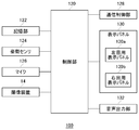
- FIG. 7 shows a functional block of the information processing device 10.
- the information processing device 10 includes a processing unit 200 and a communication unit 202, and the processing unit 200 includes an acquisition unit 210, an estimation processing unit 220, a game execution unit 230, and a marker information holding unit 240.
- the communication unit 202 receives the operation information and the sensor data transmitted from the input device 16 and supplies the operation information and the sensor data to the acquisition unit 210. Further, the communication unit 202 receives the captured image data and the sensor data transmitted from the HMD 100 and supplies the captured image data and the sensor data to the acquisition unit 210.
- the acquisition unit 210 has a captured image acquisition unit 212, a sensor data acquisition unit 214, and an operation information acquisition unit 216.
- the estimation processing unit 220 has a marker image coordinate identification unit 222, a marker image coordinate extraction unit 224, a position / orientation derivation unit 226, and a position determination unit 228, and has a position of the input device 16 based on the coordinates of the marker image in the captured image. Estimate information and attitude information.
- the estimation processing unit 220 supplies the position information and the posture information of the input device 16 to the game execution unit 230.
- the captured image acquisition unit 212 acquires an image captured by the input device 16 provided with the plurality of markers 30 and supplies the captured image to the estimation processing unit 220.
- the sensor data acquisition unit 214 acquires sensor data transmitted from the input device 16 and the HMD 100, and supplies the sensor data to the estimation processing unit 220.
- the operation information acquisition unit 216 acquires the operation information transmitted from the input device 16 and supplies it to the game execution unit 230.
- the game execution unit 230 advances the game based on the operation information and the position / orientation information of the input device 16.
- the marker image coordinate identification unit 222 specifies two-dimensional coordinates (hereinafter, also referred to as “marker image coordinates”) representing the image of the marker 30 included in the captured image.
- the marker image coordinate specifying unit 222 may specify a pixel region having a brightness value equal to or higher than a predetermined value, calculate the barycentric coordinates of the pixel region, and use the marker image coordinates as the marker image coordinates.
- the marker image coordinate specifying unit 222 ignores the pixel region having a shape and size that cannot be formed as a marker image, and calculates the coordinates of the center of gravity of the pixel region having a shape and size estimated to be a marker image. Is preferable.
- a method of solving a PNP (Perspective n-Point) problem is known as a method of estimating the position and orientation of an image pickup device that captures an image of an object whose three-dimensional shape and size are known.
- the marker image coordinate extraction unit 224 extracts N (N is an integer of 3 or more) two-dimensional marker image coordinates in the captured image
- the position / orientation derivation unit 226 is extracted by the marker image coordinate extraction unit 224.
- the position information and attitude information of the input device 16 are derived from the coordinates of the N marker images and the three-dimensional coordinates of the N markers in the three-dimensional model of the input device 16.
- the position / orientation deriving unit 226 estimates the position and orientation of the imaging device 14 using the following (Equation 1), and derives the position information and attitude information in the three-dimensional space of the input device 16 based on the estimation result. ..
- (u, v) is the marker image coordinates in the captured image
- (X, Y, Z) is the three-dimensional space of the marker 30 when the three-dimensional model of the input device 16 is in the reference position and the reference posture.
- the three-dimensional model has exactly the same shape and size as the input device 16, and the markers are arranged at the same positions.
- the marker information holding unit 240 holds the three-dimensional coordinates of each marker in the three-dimensional model in the reference position and the reference posture
- the position / orientation deriving unit 226 holds the three-dimensional coordinates of each marker from the marker information holding unit 240. Read to get (X, Y, Z).
- (F x , fy ) is the focal length of the image pickup apparatus 14, and (c x , cy ) is the principal point of the image, both of which are internal parameters of the image pickup apparatus 14.
- the matrix having r 11 to r 33 and t 1 to t 3 as elements is a rotation / parallel traveling sequence.
- (Equation 1) in (u, v), (f x, f y), (c x, c y), (X, Y, Z) are known, the position and orientation derivation unit 226, N pieces of the marker By solving the equations for 30, the rotation / parallel traveling matrix common to them is obtained.
- the position / orientation deriving unit 226 derives the position information and the attitude information of the input device 16 based on the angle and the translation amount represented by this matrix.
- the process of estimating the position / orientation of the input device 16 is performed by solving the P3P problem. Therefore, the position / orientation derivation unit 226 has three marker image coordinates and three in the three-dimensional model of the input device 16. The position and orientation of the input device 16 are derived using the three-dimensional marker coordinates of.
- the user holds the input device 16 in both hands and plays a game. Therefore, the captured image includes an image of the marker 30 of the input device 16 held by the user with the right hand and an image of the marker 30 of the input device 16 held by the user with the left hand.
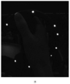
- FIG. 8 shows an example of images taken by two input devices 16.
- This captured image includes an image of the marker 30 of the input device 16 held by the right hand and an image of the marker 30 of the input device 16 held by the left hand.
- FIG. 8 shows a black-and-white inverted photographed image, and the marker image is represented by a black region.
- the input device 16 gripped by the right hand is referred to as an “input device 16a”
- the input device 16 gripped by the left hand is referred to as an “input device 16b”.
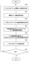
- FIG. 9 is a flowchart of estimation processing by the estimation processing unit 220.
- the marker image coordinate identification unit 222 specifies the coordinates of a plurality of marker images included in the captured image (S12). ..
- the specified plurality of marker image coordinates include both one representing the marker position of the input device 16a and one representing the marker position of the input device 16b.
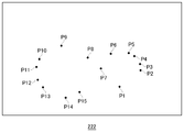
- FIG. 10 shows a state in which the marker image coordinate specifying unit 222 specifies the coordinates of a plurality of marker images included in the captured image.
- the marker image coordinate identification unit 222 specifies the marker image coordinates P1 to P15.
- the estimation processing unit 220 first estimates the position information and attitude information of either the input device 16a or the input device 16b, and then estimates the position information and attitude information of the other. At the time of initial tracking, the estimation processing unit 220 may first perform the position / orientation estimation processing of the input device 16a for the right hand (S14).
- the marker image coordinate extraction unit 224 extracts any three marker image coordinates from the marker image coordinates P1 to P15.
- the marker information holding unit 240 holds the three-dimensional coordinates of each marker in the three-dimensional model of the right-hand input device 16a and the left-hand input device 16b in the reference position and the reference posture.
- the position / orientation deriving unit 226 reads the three-dimensional coordinates of the marker in the three-dimensional model of the input device 16a for the right hand from the marker information holding unit 240, and solves the P3P problem using Equation 1.
- the position / orientation deriving unit 226 specifies the rotation / parallel traveling matrix common to the three extracted marker image coordinates
- the position / orientation deriving unit 226 can specify the marker image coordinates of the input device 16a other than the extracted three marker image coordinates.
- the position / orientation deriving unit 226 calculates the reprojection error using the marker image coordinates other than the extracted three.
- the marker image coordinate extraction unit 224 extracts a predetermined number of combinations of three marker image coordinates from the marker image coordinates P1 to P15, and the position / orientation derivation unit 226 extracts each of the extracted three marker image coordinates.
- the rotation / parallel traveling matrix is specified for the combination of, and the reprojection error of each is calculated.
- the position / orientation deriving unit 226 identifies the rotation / parallel traveling matrix that is the minimum reprojection error from a predetermined number of reprojection errors, and derives the position information and the attitude information of the input device 16a.
- the position / orientation deriving unit 226 specifies the rotation / parallel traveling matrix, so that the marker image coordinate group of the input device 16a is determined (S16).
- the marker image coordinate group of the input device 16a is the marker image coordinates P1 to P7.
- the position / orientation deriving unit 226 of the input device 16b is based on the remaining marker image coordinates P8 to P15 excluding the marker image coordinates P1 to P7 of the input device 16a. Derivation of position information and attitude information.
- the estimation processing unit 220 finishes the position / orientation estimation process of the right-hand input device 16a, and then executes the position / orientation estimation process of the left-hand input device 16b (S18).
- the marker image coordinate extraction unit 224 extracts any three marker image coordinates from the remaining marker image coordinates P8 to P15 excluding the marker image coordinates P1 to P7 of the input device 16a.
- the position / orientation deriving unit 226 reads the three-dimensional coordinates of the marker in the three-dimensional model of the input device 16b for the left hand from the marker information holding unit 240, and solves the P3P problem using Equation 1.
- the position / orientation deriving unit 226 When the position / orientation deriving unit 226 specifies the rotation / parallel traveling matrix common to the three extracted marker image coordinates, the position / orientation deriving unit 226 can specify the marker image coordinates of the input device 16b other than the extracted three marker image coordinates. The position / orientation deriving unit 226 calculates the reprojection error using the marker image coordinates other than the extracted three. When calculating the reprojection error, the position / orientation deriving unit 226 does not use the marker image coordinates P1 to P7.
- the marker image coordinate extraction unit 224 extracts a predetermined number of combinations of three marker image coordinates from the marker image coordinates P8 to P15, and the position / orientation derivation unit 226 extracts each of the extracted three marker image coordinates.
- the rotation / parallel traveling matrix is specified for the combination of, and the reprojection error of each is calculated.
- the position / orientation deriving unit 226 identifies the rotation / parallel traveling matrix that is the minimum reprojection error from a predetermined number of reprojection errors, and derives the position information and the attitude information of the input device 16b.
- the estimation processing unit 220 supplies the position information and the posture information of the input device 16a and the input device 16b to the game execution unit 230.
- the position / orientation deriving unit 226 excludes the marker image coordinates P1 to P7 from the candidates and derives the position information and the attitude information of the input device 16b, so that the amount of calculation can be reduced.
- the position determination unit 228 determines which of the input device 16a and the input device 16b is closer to the image pickup device 14 (S20). ). In this example, the position determination unit 228 determines that the left-hand input device 16b is closer to the image pickup device 14 than the right-hand input device 16a.
- the position / orientation estimation process is performed in the imaging cycle of the captured image (N in S22).
- the estimation processing unit 220 relatively from the image pickup device 14.
- the position information and attitude information of the input device 16b located at a close position are derived before the position information and attitude information of the input device 16a located at a position relatively far from the image pickup device 14. That is, in S14, the estimation processing unit 220 inputs the position information and the posture information of the input device 16b determined to be relatively close to the image pickup device 14 based on the estimation processing result using the previously captured image, to the input device 16a. Derived before.
- the input device 16a located at a position relatively far from the image pickup device 14 may be hidden from the image pickup device 14 by the input device 16b located at a relatively close position, but the reverse is not true. Therefore, the input device 16b is expected to estimate the position information and the attitude information with high accuracy, and the estimation processing unit 220 performs the estimation processing of the position information and the attitude information of the input device 16b located near the image pickup device 14. , The estimation process of the input device 16a is performed before the estimation process.
- the estimation processing unit 220 executes the position / orientation estimation process of the right-hand input device 16a after the position / orientation estimation process of the left-hand input device 16b is completed (S18).
- the marker image coordinate extraction unit 224 extracts any three marker image coordinates from the remaining marker image coordinates P1 to P7 excluding the marker image coordinates P8 to P15 of the input device 16b.
- the position / orientation derivation unit 226 reads the three-dimensional coordinates of the marker in the three-dimensional model of the input device 16a for the right hand from the marker information holding unit 240, solves the P3P problem using Equation 1, and positions and the attitude of the input device 16a. Derive information.
- the position / orientation estimation process by the estimation processing unit 220 also ends (Y in S22).
- the present invention has been described above based on examples.
- the above embodiment is an example, and it is understood by those skilled in the art that various modifications are possible for each of these components and combinations of each processing process, and that such modifications are also within the scope of the present invention. ..
- the information processing device 10 performed the estimation process, but the HMD 100 may be provided with the function of the information processing device 10 and the HMD 100 may perform the estimation process.
- the arrangement of the plurality of markers 30 in the input device 16 provided with the operating member 22 has been described, but the device to be tracked does not necessarily have to include the operating member 22.
- the position / orientation estimation process when the two input devices 16 are photographed has been described, but the position / orientation estimation process when three or more tracking target devices are photographed is also realized in the same manner.
- the imaging device 14 is attached to the HMD 100, but the imaging device 14 may be attached to a position other than the HMD 100 as long as it can capture a marker image.
- the present invention can be used in the technical field of deriving the position information and posture information of the device.
- 1 ... Information processing system, 10 ... Information processing device, 14 ... Imaging device, 16 ... Input device, 30 ... Marker, 200 ... Processing unit, 202 ... Communication unit, 210 ... acquisition unit, 212 ... captured image acquisition unit, 214 ... sensor data acquisition unit, 216 ... operation information acquisition unit, 220 ... estimation processing unit, 222 ... marker image coordinate identification Unit, 224 ... Marker image coordinate extraction unit, 226 ... Position / orientation derivation unit, 228 ... Position determination unit, 230 ... Game execution unit, 240 ... Marker information holding unit.
Landscapes
- Engineering & Computer Science (AREA)
- Multimedia (AREA)
- Human Computer Interaction (AREA)
- Physics & Mathematics (AREA)
- General Engineering & Computer Science (AREA)
- Theoretical Computer Science (AREA)
- General Physics & Mathematics (AREA)
- Optics & Photonics (AREA)
- Health & Medical Sciences (AREA)
- Life Sciences & Earth Sciences (AREA)
- Biophysics (AREA)
- Cardiology (AREA)
- General Health & Medical Sciences (AREA)
- Heart & Thoracic Surgery (AREA)
- Position Input By Displaying (AREA)
- User Interface Of Digital Computer (AREA)
Priority Applications (1)
| Application Number | Priority Date | Filing Date | Title |
|---|---|---|---|
| US17/440,869 US11794095B2 (en) | 2019-04-24 | 2020-04-17 | Information processing apparatus and device information derivation method |
Applications Claiming Priority (2)
| Application Number | Priority Date | Filing Date | Title |
|---|---|---|---|
| JP2019-083059 | 2019-04-24 | ||
| JP2019083059A JP7288792B2 (ja) | 2019-04-24 | 2019-04-24 | 情報処理装置およびデバイス情報導出方法 |
Publications (1)
| Publication Number | Publication Date |
|---|---|
| WO2020218182A1 true WO2020218182A1 (ja) | 2020-10-29 |
Family
ID=72942554
Family Applications (1)
| Application Number | Title | Priority Date | Filing Date |
|---|---|---|---|
| PCT/JP2020/016854 Ceased WO2020218182A1 (ja) | 2019-04-24 | 2020-04-17 | 情報処理装置およびデバイス情報導出方法 |
Country Status (3)
| Country | Link |
|---|---|
| US (1) | US11794095B2 (https=) |
| JP (1) | JP7288792B2 (https=) |
| WO (1) | WO2020218182A1 (https=) |
Families Citing this family (2)
| Publication number | Priority date | Publication date | Assignee | Title |
|---|---|---|---|---|
| JP7828715B2 (ja) | 2020-10-29 | 2026-03-12 | Ntn株式会社 | 転がり軸受 |
| JP2024106855A (ja) * | 2023-01-27 | 2024-08-08 | 株式会社ソニー・インタラクティブエンタテインメント | 情報処理装置およびデバイス位置取得方法 |
Citations (5)
| Publication number | Priority date | Publication date | Assignee | Title |
|---|---|---|---|---|
| JP2007296248A (ja) * | 2006-05-02 | 2007-11-15 | Sony Computer Entertainment Inc | ゲーム装置 |
| WO2011145180A1 (ja) * | 2010-05-18 | 2011-11-24 | 富士通株式会社 | ポインタ情報処理装置、ポインタ情報処理プログラムおよび会議システム |
| WO2016157807A1 (ja) * | 2015-03-27 | 2016-10-06 | セイコーエプソン株式会社 | インタラクティブプロジェクター,インタラクティブプロジェクションシステム,およびインタラクティブプロジェクターの制御方法 |
| JP2018032102A (ja) * | 2016-08-22 | 2018-03-01 | 株式会社コロプラ | 仮想空間を提供する方法、仮想体験を提供する方法、プログラム、および記録媒体 |
| JP2019061528A (ja) * | 2017-09-27 | 2019-04-18 | 株式会社Cygames | プログラム、情報処理方法、情報処理システム、頭部装着型表示装置、情報処理装置 |
Family Cites Families (16)
| Publication number | Priority date | Publication date | Assignee | Title |
|---|---|---|---|---|
| JPS5714108U (https=) | 1980-06-28 | 1982-01-25 | ||
| JP2005135425A (ja) | 1998-02-16 | 2005-05-26 | Sony Computer Entertainment Inc | 携帯用電子機器の保護ケース |
| JP5089060B2 (ja) | 2006-03-14 | 2012-12-05 | 株式会社ソニー・コンピュータエンタテインメント | エンタテインメントシステムおよびゲームコントローラ |
| JP4443531B2 (ja) | 2006-04-11 | 2010-03-31 | 株式会社ソニー・コンピュータエンタテインメント | エンタテインメントシステムおよび処理装置 |
| CN102124423A (zh) | 2008-01-22 | 2011-07-13 | 新世代株式会社 | 摄像装置、在线游戏系统、操作物、输入方法、图像解析装置、图像解析方法以及记录媒体 |
| EP2354896B1 (en) | 2008-11-14 | 2016-12-21 | Sony Interactive Entertainment Inc. | Operating device and information processing apparatus |
| JPWO2013157052A1 (ja) | 2012-04-20 | 2015-12-21 | 任天堂株式会社 | ゲームコントローラ |
| WO2015079715A1 (ja) | 2013-11-30 | 2015-06-04 | 株式会社五藤光学研究所 | 恒星投映筒 |
| US9649558B2 (en) | 2014-03-14 | 2017-05-16 | Sony Interactive Entertainment Inc. | Gaming device with rotatably placed cameras |
| JP6355978B2 (ja) | 2014-06-09 | 2018-07-11 | 株式会社バンダイナムコエンターテインメント | プログラムおよび画像生成装置 |
| US9746921B2 (en) | 2014-12-31 | 2017-08-29 | Sony Interactive Entertainment Inc. | Signal generation and detector systems and methods for determining positions of fingers of a user |
| JP6650739B2 (ja) | 2015-11-30 | 2020-02-19 | 株式会社ソニー・インタラクティブエンタテインメント | 発光デバイス調整装置および駆動電流調整方法 |
| JP6917701B2 (ja) * | 2016-11-30 | 2021-08-11 | キヤノン株式会社 | 情報処理装置、情報処理装置の制御方法及びプログラム |
| US11490808B2 (en) | 2017-07-27 | 2022-11-08 | Sony Corporation | Information processing device and information processing method |
| US10529074B2 (en) | 2017-09-28 | 2020-01-07 | Samsung Electronics Co., Ltd. | Camera pose and plane estimation using active markers and a dynamic vision sensor |
| JP6853156B2 (ja) * | 2017-09-29 | 2021-03-31 | 株式会社日立製作所 | 姿勢推定システム、姿勢推定装置、及び距離画像カメラ |
-
2019
- 2019-04-24 JP JP2019083059A patent/JP7288792B2/ja active Active
-
2020
- 2020-04-17 WO PCT/JP2020/016854 patent/WO2020218182A1/ja not_active Ceased
- 2020-04-17 US US17/440,869 patent/US11794095B2/en active Active
Patent Citations (5)
| Publication number | Priority date | Publication date | Assignee | Title |
|---|---|---|---|---|
| JP2007296248A (ja) * | 2006-05-02 | 2007-11-15 | Sony Computer Entertainment Inc | ゲーム装置 |
| WO2011145180A1 (ja) * | 2010-05-18 | 2011-11-24 | 富士通株式会社 | ポインタ情報処理装置、ポインタ情報処理プログラムおよび会議システム |
| WO2016157807A1 (ja) * | 2015-03-27 | 2016-10-06 | セイコーエプソン株式会社 | インタラクティブプロジェクター,インタラクティブプロジェクションシステム,およびインタラクティブプロジェクターの制御方法 |
| JP2018032102A (ja) * | 2016-08-22 | 2018-03-01 | 株式会社コロプラ | 仮想空間を提供する方法、仮想体験を提供する方法、プログラム、および記録媒体 |
| JP2019061528A (ja) * | 2017-09-27 | 2019-04-18 | 株式会社Cygames | プログラム、情報処理方法、情報処理システム、頭部装着型表示装置、情報処理装置 |
Also Published As
| Publication number | Publication date |
|---|---|
| US11794095B2 (en) | 2023-10-24 |
| JP7288792B2 (ja) | 2023-06-08 |
| US20220161127A1 (en) | 2022-05-26 |
| JP2020181321A (ja) | 2020-11-05 |
Similar Documents
| Publication | Publication Date | Title |
|---|---|---|
| JP7248490B2 (ja) | 情報処理装置、デバイスの位置および姿勢の推定方法 | |
| JP7198149B2 (ja) | 情報処理装置およびデバイス情報導出方法 | |
| JP7283958B2 (ja) | 複数のマーカを備えたデバイス | |
| WO2020189450A1 (ja) | 複数のマーカを備えたデバイス | |
| WO2020218182A1 (ja) | 情報処理装置およびデバイス情報導出方法 | |
| US20250095193A1 (en) | Information processing apparatus and representative coordinate derivation method | |
| WO2023238678A1 (ja) | 情報処理装置、コントローラ表示方法およびコンピュータプログラム | |
| JP2024106855A (ja) | 情報処理装置およびデバイス位置取得方法 | |
| JP7634069B2 (ja) | 複数のマーカを備えたデバイス | |
| US20240257391A1 (en) | Information processing apparatus and device information derivation method | |
| US12353648B2 (en) | Information processing apparatus and device position estimation method | |
| US12314487B2 (en) | Information processing apparatus, device speed estimation method, and device position estimation method | |
| US20250308061A1 (en) | Information processing apparatus and representative coordinate derivation method | |
| WO2023157338A1 (ja) | 情報処理装置およびデバイス位置推定方法 |
Legal Events
| Date | Code | Title | Description |
|---|---|---|---|
| 121 | Ep: the epo has been informed by wipo that ep was designated in this application |
Ref document number: 20796101 Country of ref document: EP Kind code of ref document: A1 |
|
| NENP | Non-entry into the national phase |
Ref country code: DE |
|
| 122 | Ep: pct application non-entry in european phase |
Ref document number: 20796101 Country of ref document: EP Kind code of ref document: A1 |