WO2020217876A1 - マニホールド - Google Patents
マニホールド Download PDFInfo
- Publication number
- WO2020217876A1 WO2020217876A1 PCT/JP2020/014726 JP2020014726W WO2020217876A1 WO 2020217876 A1 WO2020217876 A1 WO 2020217876A1 JP 2020014726 W JP2020014726 W JP 2020014726W WO 2020217876 A1 WO2020217876 A1 WO 2020217876A1
- Authority
- WO
- WIPO (PCT)
- Prior art keywords
- hole
- joint
- flow path
- insertion hole
- tube
- Prior art date
- Legal status (The legal status is an assumption and is not a legal conclusion. Google has not performed a legal analysis and makes no representation as to the accuracy of the status listed.)
- Ceased
Links
Images




Classifications
-
- F—MECHANICAL ENGINEERING; LIGHTING; HEATING; WEAPONS; BLASTING
- F16—ENGINEERING ELEMENTS AND UNITS; GENERAL MEASURES FOR PRODUCING AND MAINTAINING EFFECTIVE FUNCTIONING OF MACHINES OR INSTALLATIONS; THERMAL INSULATION IN GENERAL
- F16K—VALVES; TAPS; COCKS; ACTUATING-FLOATS; DEVICES FOR VENTING OR AERATING
- F16K27/00—Construction of housing; Use of materials therefor
-
- F—MECHANICAL ENGINEERING; LIGHTING; HEATING; WEAPONS; BLASTING
- F16—ENGINEERING ELEMENTS AND UNITS; GENERAL MEASURES FOR PRODUCING AND MAINTAINING EFFECTIVE FUNCTIONING OF MACHINES OR INSTALLATIONS; THERMAL INSULATION IN GENERAL
- F16L—PIPES; JOINTS OR FITTINGS FOR PIPES; SUPPORTS FOR PIPES, CABLES OR PROTECTIVE TUBING; MEANS FOR THERMAL INSULATION IN GENERAL
- F16L41/00—Branching pipes; Joining pipes to walls
- F16L41/02—Branch units, e.g. made in one piece, welded, riveted
- F16L41/03—Branch units, e.g. made in one piece, welded, riveted comprising junction pieces for four or more pipe members
-
- F—MECHANICAL ENGINEERING; LIGHTING; HEATING; WEAPONS; BLASTING
- F16—ENGINEERING ELEMENTS AND UNITS; GENERAL MEASURES FOR PRODUCING AND MAINTAINING EFFECTIVE FUNCTIONING OF MACHINES OR INSTALLATIONS; THERMAL INSULATION IN GENERAL
- F16L—PIPES; JOINTS OR FITTINGS FOR PIPES; SUPPORTS FOR PIPES, CABLES OR PROTECTIVE TUBING; MEANS FOR THERMAL INSULATION IN GENERAL
- F16L37/00—Couplings of the quick-acting type
- F16L37/08—Couplings of the quick-acting type in which the connection between abutting or axially overlapping ends is maintained by locking members
- F16L37/084—Couplings of the quick-acting type in which the connection between abutting or axially overlapping ends is maintained by locking members combined with automatic locking
- F16L37/091—Couplings of the quick-acting type in which the connection between abutting or axially overlapping ends is maintained by locking members combined with automatic locking by means of a ring provided with teeth or fingers
-
- F—MECHANICAL ENGINEERING; LIGHTING; HEATING; WEAPONS; BLASTING
- F16—ENGINEERING ELEMENTS AND UNITS; GENERAL MEASURES FOR PRODUCING AND MAINTAINING EFFECTIVE FUNCTIONING OF MACHINES OR INSTALLATIONS; THERMAL INSULATION IN GENERAL
- F16K—VALVES; TAPS; COCKS; ACTUATING-FLOATS; DEVICES FOR VENTING OR AERATING
- F16K11/00—Multiple-way valves, e.g. mixing valves; Pipe fittings incorporating such valves
- F16K11/02—Multiple-way valves, e.g. mixing valves; Pipe fittings incorporating such valves with all movable sealing faces moving as one unit
- F16K11/06—Multiple-way valves, e.g. mixing valves; Pipe fittings incorporating such valves with all movable sealing faces moving as one unit comprising only sliding valves, i.e. sliding closure elements
- F16K11/065—Multiple-way valves, e.g. mixing valves; Pipe fittings incorporating such valves with all movable sealing faces moving as one unit comprising only sliding valves, i.e. sliding closure elements with linearly sliding closure members
- F16K11/07—Multiple-way valves, e.g. mixing valves; Pipe fittings incorporating such valves with all movable sealing faces moving as one unit comprising only sliding valves, i.e. sliding closure elements with linearly sliding closure members with cylindrical slides
-
- F—MECHANICAL ENGINEERING; LIGHTING; HEATING; WEAPONS; BLASTING
- F16—ENGINEERING ELEMENTS AND UNITS; GENERAL MEASURES FOR PRODUCING AND MAINTAINING EFFECTIVE FUNCTIONING OF MACHINES OR INSTALLATIONS; THERMAL INSULATION IN GENERAL
- F16K—VALVES; TAPS; COCKS; ACTUATING-FLOATS; DEVICES FOR VENTING OR AERATING
- F16K27/00—Construction of housing; Use of materials therefor
- F16K27/003—Housing formed from a plurality of the same valve elements
-
- F—MECHANICAL ENGINEERING; LIGHTING; HEATING; WEAPONS; BLASTING
- F16—ENGINEERING ELEMENTS AND UNITS; GENERAL MEASURES FOR PRODUCING AND MAINTAINING EFFECTIVE FUNCTIONING OF MACHINES OR INSTALLATIONS; THERMAL INSULATION IN GENERAL
- F16L—PIPES; JOINTS OR FITTINGS FOR PIPES; SUPPORTS FOR PIPES, CABLES OR PROTECTIVE TUBING; MEANS FOR THERMAL INSULATION IN GENERAL
- F16L41/00—Branching pipes; Joining pipes to walls
- F16L41/02—Branch units, e.g. made in one piece, welded, riveted
Definitions
- the present invention relates to a manifold provided with a joint into which a flexible circular tubular tube is inserted.
- the manifold includes a plurality of manifold blocks, a plurality of solenoid valves, and a plurality of joints.
- the plurality of manifold blocks are arranged side by side in one direction.
- a flow path is formed inside each manifold block.
- the solenoid valve is mounted on the manifold block.
- a tubular joint protrudes outward from the manifold block.
- the joint has a tube insertion hole that communicates with the flow path of the manifold block.
- the plurality of joints are adjacent to each other in the parallel direction of the manifold blocks. For example, a flexible circular tubular tube is inserted into the tube insertion hole.
- a tube with a large flow path cross-sectional area may be inserted into the tube insertion hole.
- increasing the hole diameter of the tube insertion hole also increases the outer diameter of the joint. Therefore, if the outer diameter of the joint is made too large, the joints adjacent to each other in the parallel direction of the manifold blocks tend to interfere with each other.
- the pitch between adjacent manifold blocks is increased, the physique of the manifold increases in the juxtaposed direction of the manifold blocks.
- An object of the present invention is to provide a manifold capable of increasing the flow rate of the fluid flowing through the flow path while suppressing the increase in size.
- a plurality of flow path forming members arranged side by side in one direction and a flow path is formed inside, and the plurality of flow path forming members.
- a plurality of tubular joints having tube insertion holes communicating with each of the plurality of flow paths are provided, and the plurality of joints are formed of the plurality of flow path forming members.
- manifolds in which flexible circular tubular tubes are inserted into the tube insertion holes of the plurality of joints that are adjacent to each other in the parallel direction.
- each of the plurality of joints protruding from the flow path forming member has a long tubular shape, and when the joint is viewed from the axial direction, the lateral direction of the joint coincides with the parallel direction. ing. At least a part of the tube insertion hole is an elongated small-diameter hole. Further, when the joint is viewed from the axial direction, the lateral direction of the small diameter hole coincides with the lateral direction of the joint.
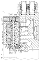
- FIG. 5-5 is a sectional view taken along line 5-5 in FIG.
- the front view of the first joint in another embodiment.
- the front view of the first joint in another embodiment.
- the perspective view of the 1st joint in another embodiment.
- the manifold of this embodiment is a solenoid valve manifold including a plurality of solenoid valves.
- the solenoid valve manifold 10 includes a first end block 11, a second end block 12, a supply / discharge block 13, and a plurality of manifold blocks 14.
- the first end block 11, the second end block 12, the supply / discharge block 13, and the plurality of manifold blocks 14 are arranged side by side in this order in one direction.
- the supply / discharge block 13 is provided with a supply joint 13a and a discharge joint 13b.
- the first end portion of the supply joint 13a communicates with a centralized supply flow path (not shown) formed inside the supply / discharge block 13.
- the second end of the supply joint 13a is connected to a fluid supply source (not shown) via a pipe or the like.
- the first end portion of the discharge joint 13b communicates with a centralized discharge flow path (not shown) formed inside the supply / discharge block 13.
- the second end of the discharge joint 13b is open to the atmosphere via a pipe or the like.
- a solenoid valve 20 is mounted on each of the plurality of manifold blocks 14. Further, the solenoid valve manifold 10 includes a power supply block 15 for supplying electric power to each solenoid valve 20.
- the power supply block 15 is arranged on the side opposite to the manifold block 14 with respect to the first end block 11.
- the first end block 11, the second end block 12, the supply / discharge block 13, the plurality of manifold blocks 14, and the power supply block 15 have an elongated square block shape. Adjacent blocks are connected in contact with each other.
- each solenoid valve 20 has an elongated square block-shaped valve body 21.
- the valve body 21 is mounted on the mounting surface 14a of the manifold block 14.
- the valve body 21 is connected to the elongated square block-shaped body body 22, the first connecting block 23 connected to the first end portion in the longitudinal direction of the body body 22, and the second end portion in the longitudinal direction of the body body 22.
- It has a second connecting block 24 to be formed.
- the body body 22, the first connecting block 23, and the second connecting block 24 are made of, for example, a synthetic resin material.
- the body main body 22 has a main body facing surface 22a facing the mounting surface 14a.
- the first connecting block 23 has a first facing surface 23a facing the mounting surface 14a.
- the second connecting block 24 has a second facing surface 24a facing the mounting surface 14a.
- the body body 22 is formed with a circular valve hole 26 in which the valve body 25 is housed.
- the valve hole 26 extends in the longitudinal direction of the body body 22.
- the first end of the valve hole 26 is open to the first end surface of the body body 22 in the longitudinal direction.
- the second end of the valve hole 26 is open to the second end surface of the body body 22 in the longitudinal direction. Therefore, the valve hole 26 penetrates in the longitudinal direction of the body body 22.
- the valve body 25 is a spool valve body housed in the valve hole 26.
- the valve body 25 can reciprocate in the valve hole 26.
- the body body 22 is formed with a supply port 27, a first output port 28, a second output port 29, a first discharge port 30, and a second discharge port 31.
- the solenoid valve 20 is a 5-port solenoid valve.
- the first discharge port 30, the first output port 28, the supply port 27, the second output port 29, and the second discharge port 31 are arranged in this order from the first end portion to the second end portion of the body body 22.
- the first ends of the supply port 27, the first output port 28, the second output port 29, the first discharge port 30, and the second discharge port 31 communicate with the valve hole 26.
- the second ends of the supply port 27, the first output port 28, the second output port 29, the first discharge port 30, and the second discharge port 31 are open to the main body facing surface 22a of the body main body 22.
- a first valve seat 32 is provided between the supply port 27 and the first output port 28.
- a second valve seat 33 is provided between the first output port 28 and the first discharge port 30 on the inner peripheral surface of the valve hole 26.
- a third valve seat 34 is provided between the supply port 27 and the second output port 29.
- a fourth valve seat 35 is provided between the second output port 29 and the second discharge port 31.
- the first valve seat 32, the second valve seat 33, the third valve seat 34, and the fourth valve seat 35 form a part of the inner peripheral surface of the valve hole 26 and are formed in an annular shape.
- valve hole 26 has a first hole portion 26a.
- the first hole portion 26a communicates with the first discharge port 30 and forms the first end portion of the valve hole 26 arranged apart from the second valve seat 33.
- the valve hole 26 has a second hole portion 26b.
- the second hole portion 26b communicates with the second discharge port 31 and forms a second end portion of the valve hole 26 arranged apart from the fourth valve seat 35.
- the inner diameters of the first valve seat 32, the second valve seat 33, the third valve seat 34, the fourth valve seat 35, the first hole portion 26a, and the second hole portion 26b are the same.
- the first valve portion 251 and the second valve portion 252, the third valve portion 253, the fourth valve portion 254, the fifth valve portion 255, and the sixth valve portion 256 are provided in the axial direction of the valve body 25. They are provided separately from each other.
- the fifth valve portion 255, the second valve portion 252, the first valve portion 251 and the third valve portion 253, the fourth valve portion 254, and the sixth valve portion 256 are, in this order, the first in the axial direction of the valve body 25. It is arranged from the end to the second end.
- the outer diameters of the first valve portion 251 and the second valve portion 252, the third valve portion 253, the fourth valve portion 254, the fifth valve portion 255, and the sixth valve portion 256 are the same.
- the valve body 25 includes a first shaft portion 25a that connects the first valve portion 251 and the third valve portion 253, a second shaft portion 25b that connects the first valve portion 251 and the second valve portion 252, and a second shaft portion 25b. It has a third shaft portion 25c that connects the three valve portions 253 and the fourth valve portion 254. Further, the valve body 25 includes a fourth shaft portion 25d that connects the second valve portion 252 and the fifth valve portion 255, and a fifth shaft portion 25e that connects the fourth valve portion 254 and the sixth valve portion 256. have.
- the valve body 25 has a columnar first protruding portion 25f.
- the first protruding portion 25f protrudes from the end surface of the fifth valve portion 255 opposite to the fourth shaft portion 25d.
- the first protruding portion 25f is the first end portion of the valve body 25 in the axial direction.
- the valve body 25 has a columnar second protruding portion 25 g.
- the second protruding portion 25g protrudes from the end surface of the sixth valve portion 256 opposite to the fifth shaft portion 25e.
- the second protruding portion 25g is the second end portion in the axial direction of the valve body 25.
- the outer diameters of the first shaft portion 25a, the second shaft portion 25b, the third shaft portion 25c, the fourth shaft portion 25d, the fifth shaft portion 25e, the first protruding portion 25f, and the second protruding portion 25g are the same. is there.
- the outer diameters of the first valve portion 251 and the second valve portion 252, the third valve portion 253, the fourth valve portion 254, the fifth valve portion 255, and the sixth valve portion 256 are the first shaft portion 25a and the second. It is larger than the outer diameters of the shaft portion 25b, the third shaft portion 25c, the fourth shaft portion 25d, the fifth shaft portion 25e, the first protruding portion 25f, and the second protruding portion 25g.
- the first spool packing 36 is mounted on the outer peripheral surface of the first valve portion 251.
- the first spool packing 36 seals between the supply port 27 and the first output port 28 when the first valve portion 251 is seated on the first valve seat 32.
- a second spool packing 37 is mounted on the outer peripheral surface of the second valve portion 252.
- the second spool packing 37 seals between the first output port 28 and the first discharge port 30 when the second valve portion 252 is seated on the second valve seat 33.
- a third spool packing 38 is mounted on the outer peripheral surface of the third valve portion 253.
- the third spool packing 38 seals between the supply port 27 and the second output port 29 when the third valve portion 253 is seated on the third valve seat 34.
- a fourth spool packing 39 is mounted on the outer peripheral surface of the fourth valve portion 254.
- the fourth spool packing 39 seals between the second output port 29 and the second discharge port 31 when the fourth valve portion 254 is seated on the fourth valve seat 35.
- the first spool packing 36, the second spool packing 37, the third spool packing 38, and the fourth spool packing 39 are made of rubber and have an annular shape.
- the first connecting block 23 is formed with a circular hole-shaped first piston accommodating recess 41 communicating with the first hole 26a.
- the first protruding portion 25f of the valve body 25 can appear and disappear from the first hole portion 26a into the first piston accommodating recess 41.
- a disc-shaped first piston 42 is housed in the first piston housing recess 41 so as to be reciprocating.
- the first piston 42 is attached to the tip of the first protruding portion 25f of the valve body 25.
- a first lip packing 43 is mounted on the outer peripheral surface of the first piston 42.
- the first lip packing 43 seals between the first piston 42 and the inner peripheral surface of the first piston accommodating recess 41.
- the first piston pressure acting chamber 44 is partitioned in the first piston accommodating recess 41 by the first piston 42. Pilot fluid is supplied and discharged to the first pilot pressure action chamber 44.
- the second connecting block 24 is formed with a circular hole-shaped second piston accommodating recess 45 communicating with the second hole portion 26b.
- the inner diameter of the second piston accommodating recess 45 is smaller than the inner diameter of the first piston accommodating recess 41.
- the second protruding portion 25g of the valve body 25 can appear and disappear from the second hole portion 26b into the second piston accommodating recess 45.
- a disc-shaped second piston 46 is housed in the second piston accommodating recess 45 so as to be reciprocating.
- the second piston 46 is attached to the tip of the second protruding portion 25 g of the valve body 25.
- the outer diameter of the second piston 46 is smaller than the outer diameter of the first piston 42.
- a second lip packing 47 is mounted on the outer peripheral surface of the second piston 46.
- the second lip packing 47 seals between the second piston 46 and the inner peripheral surface of the second piston accommodating recess 45.
- a second pilot pressure acting chamber 48 is partitioned in the second piston accommodating recess 45 by the second piston 46. Pilot fluid is supplied and discharged to the second pilot pressure action chamber 48.
- the outer diameter of the second piston 46 is smaller than the outer diameter of the first piston 42. Therefore, the pressure receiving area of the second piston 46 that receives the pressure of the pilot fluid in the second pilot pressure acting chamber 48 is larger than the pressure receiving area of the first piston 42 that receives the pressure of the pilot fluid in the first pilot pressure acting chamber 44. Is also small.
- a first sealing member 49a that seals between the fifth valve portion 255 and the first hole portion 26a is mounted on the outer peripheral surface of the fifth valve portion 255.
- the first seal member 49a is made of annular rubber. The first seal member 49a suppresses the leakage of fluid from the first discharge port 30 to the first piston accommodating recess 41 via the first hole portion 26a.
- a second sealing member 49b that seals between the sixth valve portion 256 and the second hole portion 26b is mounted on the outer peripheral surface of the sixth valve portion 256.
- the second seal member 49b is made of annular rubber. The second seal member 49b suppresses the leakage of fluid from the second discharge port 31 to the second piston accommodating recess 45 via the second hole portion 26b.
- Each solenoid valve 20 has a pilot valve portion 50, respectively.
- the solenoid valve 20 is a so-called single pilot type in which one pilot valve portion 50 is provided.
- the pilot valve portion 50 includes a solenoid portion 51.
- the pilot valve portion 50 is connected to an end portion of the first connecting block 23 opposite to the body main body 22.
- valve body 21 is formed with a pilot fluid supply flow path 52 communicating with the supply port 27 via the valve hole 26.
- the pilot fluid supply flow path 52 is opened in the valve hole 26 at a position communicating with the supply port 27 regardless of the position of the valve body 25.
- the pilot fluid supply flow path 52 branches in the middle and is connected to the pilot valve portion 50 and the second pilot pressure action chamber 48, respectively. The fluid from the supply port 27 is constantly supplied to the second pilot pressure action chamber 48 as the pilot fluid via the pilot fluid supply flow path 52.
- the first connecting block 23 is formed with a pilot fluid output flow path 53 that connects the pilot valve portion 50 and the first pilot pressure acting chamber 44. Further, the first connecting block 23 is formed with a solenoid valve side pilot fluid discharge flow path 54 for discharging the pilot fluid. The first end of the solenoid valve side pilot fluid discharge flow path 54 is connected to the pilot valve portion 50. The second end of the solenoid valve side pilot fluid discharge flow path 54 is open to the first facing surface 23a of the first connecting block 23.
- a supply flow path 60, a first output flow path 61, a second output flow path 62, a first discharge flow path 63, and a second discharge flow path 64 are formed in each manifold block 14. Therefore, the plurality of manifold blocks 14 are a plurality of flow path forming members that are arranged side by side in one direction and have a flow path formed therein.
- the supply flow path 60, the first output flow path 61, the second output flow path 62, the first discharge flow path 63, and the second discharge flow path 64 are open to the mounting surface 14a, respectively.
- the end of the supply flow path 60 that opens to the mounting surface 14a communicates with the supply port 27.
- the end of the first output flow path 61 that opens to the mounting surface 14a communicates with the first output port 28.
- the end of the second output flow path 62 that opens to the mounting surface 14a communicates with the second output port 29.
- the end of the first discharge flow path 63 that opens to the mounting surface 14a communicates with the first discharge port 30.
- the end of the second discharge flow path 64 that opens to the mounting surface 14a communicates with the second discharge port 31.
- the end of the supply flow path 60 on the opposite side of the mounting surface 14a penetrates each manifold block 14 in the parallel direction of the plurality of manifold blocks 14.
- the supply flow paths 60 of the adjacent manifold blocks 14 communicate with each other.
- the end of the first discharge flow path 63 opposite to the mounting surface 14a and the end of the second discharge flow path 64 opposite to the mounting surface 14a are oriented in the juxtaposed direction of the plurality of manifold blocks 14. , Penetrating each manifold block 14.
- the first discharge flow paths 63 of the adjacent manifold blocks 14 communicate with each other.
- the second discharge flow paths 64 of the adjacent manifold blocks 14 communicate with each other.
- each end of the supply flow path 60, the first discharge flow path 63, and the second discharge flow path 64 is closed by the first end block 11.
- each end of the first discharge flow path 63 and the second discharge flow path 64 communicates with the centralized discharge flow path of the supply / discharge block 13.
- each manifold block 14 is formed with a block-side pilot fluid discharge flow path 65.
- the first end of the block-side pilot fluid discharge flow path 65 opens at the portion of the mounting surface 14a facing the first facing surface 23a of the first connecting block 23, and the solenoid valve-side pilot fluid discharge flow path 54. Communicate with.
- the second end of the block-side pilot fluid discharge flow path 65 communicates with the first discharge flow path 63.
- the solenoid valve manifold 10 includes a gasket 70 that seals between the mounting surface 14a and the valve body 21.
- the gasket 70 is arranged between the mounting surface 14a and the valve body 21.
- the solenoid valve manifold 10 includes a check valve 71 that blocks the flow of fluid from the block-side pilot fluid discharge flow path 65 to the solenoid valve-side pilot fluid discharge flow path 54.
- the check valve 71 When the pressure inside the check valve 71 reaches a predetermined pressure, the check valve 71 opens. Then, the check valve 71 allows the flow of fluid from the solenoid valve side pilot fluid discharge flow path 54 to the block side pilot fluid discharge flow path 65. Therefore, the fluid that has flowed into the check valve 71 from the solenoid valve side pilot fluid discharge flow path 54 flows out to the block side pilot fluid discharge flow path 65 via the check valve 71. Further, when the pressure in the check valve 71 is smaller than a predetermined pressure, the check valve 71 is closed. As a result, the check valve 71 blocks the flow of fluid from the block-side pilot fluid discharge flow path 65 to the solenoid valve-side pilot fluid discharge flow path 54.
- the end of the first output flow path 61 opposite to the mounting surface 14a is open on the side surface 14e of each manifold block 14 orthogonal to the parallel direction of the plurality of manifold blocks 14.
- the end of the second output flow path 62 opposite to the mounting surface 14a is also opened on the side surface 14e of each manifold block 14.
- the end of the second output flow path 62 opposite to the mounting surface 14a is located closer to the mounting surface 14a than the end of the first output flow path 61 opposite to the mounting surface 14a. There is.
- Each manifold block 14 is provided with a tubular first joint 81 and a tubular second joint 82, respectively.
- the first joint 81 is connected to an end portion of the first output flow path 61 opposite to the mounting surface 14a.
- the second joint 82 is connected to an end portion of the second output flow path 62 opposite to the mounting surface 14a. Therefore, the end of the first output flow path 61 on the opposite side of the mounting surface 14a is the first joint connection hole 61e, which is the joint connection hole to which the first joint 81 is connected.
- the end of the second output flow path 62 opposite to the mounting surface 14a is a second joint connection hole 62e, which is a joint connection hole to which the second joint 82 is connected.
- the inside of the first joint 81 communicates with the first output flow path 61.
- the inside of the second joint 82 communicates with the second output flow path 62.
- Each of the first joint 81 and each second joint 82 is a tubular joint into which a flexible circular tubular tube 80 is inserted.
- the plurality of first joints 81 are adjacent to each other in the juxtaposed direction of the plurality of manifold blocks 14.
- the plurality of second joints 82 are adjacent to each other in the juxtaposed direction of the plurality of manifold blocks 14.
- Each tube 80 connected to each first joint 81 or each second joint 82 is connected to a fluid pressure device (not shown).
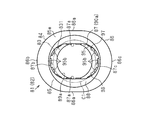
- FIG. 3 and 4 show the configuration of the first joint 81 in detail. Since the configuration of the second joint 82 is the same as the configuration of the first joint 81, detailed description of the second joint 82 will be omitted.
- the first joint 81 includes a tubular joint main body 83 and a push ring 84 attached to the joint main body 83.
- the push ring 84 is made of resin.
- the push ring 84 has a long tubular ring main body portion 85 and an annular ring collar portion 86.
- the ring flange portion 86 projects radially outward from the first end portion in the axial direction of the ring main body portion 85 on the outer peripheral surface of the ring main body portion 85.
- the outer peripheral surface of the ring main body 85 includes a ring peripheral surface 85a, a ring locking surface 85b, and a ring inclined surface 85c.
- the ring peripheral surface 85a is continuous with the ring flange portion 86 and extends in the axial direction of the ring main body portion 85.
- the ring locking surface 85b projects radially outward from the edge of the ring peripheral surface 85a on the side opposite to the ring flange portion 86.
- the ring locking surface 85b is annular.
- the outer peripheral edge of the ring locking surface 85b is located closer to the axis of the ring main body 85 than the outer peripheral surface of the ring flange 86.
- the ring inclined surface 85c is continuous with the outer peripheral edge of the ring locking surface 85b and extends in a direction away from the ring peripheral surface 85a.
- the outer diameter of the ring main body 85 becomes smaller as the distance from the ring peripheral surface 85a increases. Therefore, the end of the push ring 84 opposite to the ring collar 86, that is, the tip of the push ring 84 is hook-shaped.
- the outer peripheral surfaces of the ring collar 86 have a pair of collar planes 86a extending in parallel with each other. Further, the outer peripheral surface of the ring flange portion 86 connects the first flange portion curved surface 86b that connects the first ends of the pair of collar portion planes 86a and the second end portions of the pair of collar portion planes 86a. It has a second flange curved surface 86c. Therefore, when the ring collar portion 86 is viewed from the axial direction of the ring main body portion 85, the outer peripheral surface of the ring collar portion 86 has an oval shape.
- the ring main body 85 has a first insertion hole 87 and a diameter reduction hole 88.
- the first insertion hole 87 extends from the tip of the ring main body 85 toward the ring collar 86 in the axial direction of the ring main body 85.
- the inner peripheral surface of the first insertion hole 87 has an elongated hole shape.
- the inner peripheral surface of the first insertion hole 87 has a pair of planes 87a extending in parallel with each other.
- the inner peripheral surface of the first insertion hole 87 is a first curved surface 87b that connects the first ends of the pair of planes 87a and a second curved surface that connects the second ends of the pair of planes 87a. It has 87c.
- the pair of flat surfaces 87a are parallel to the pair of flange flat surfaces 86a.
- the first curved surface 87b extends along the curved surface 86b of the first flange portion
- the second curved surface 87c is curved the second flange portion. It extends along surface 86c. Therefore, when the push ring 84 is viewed from the axial direction of the ring main body 85, the inner peripheral surface of the first insertion hole 87 has an oval shape, which is similar to the outer peripheral surface of the ring collar 86.
- the direction orthogonal to the pair of planes 87a is the lateral direction of the first insertion hole 87, and the direction extending along the pair of planes 87a is. , The longitudinal direction of the first insertion hole 87.
- the reduced diameter hole 88 connects the end edge of the first insertion hole 87 opposite to the tip of the ring main body 85 and the end surface 85e of the ring main body 85.
- the inner peripheral surfaces of the reduced diameter holes 88 have a pair of guide surfaces 88a extending in parallel with each other.
- One of the pair of guide surfaces 88a is continuous with one of the pair of planes 87a of the first insertion hole 87.
- the other of the pair of guide surfaces 88a is continuous with the other of the pair of planes 87a of the first insertion hole 87.
- the inner peripheral surface of the reduced diameter hole 88 has a first curved surface 88b that connects the first ends of the pair of guide surfaces 88a and a second curved surface that connects the second ends of the pair of guide surfaces 88a. It has a surface 88c.
- the first curved surface 88b is continuous with the first curved surface 87b of the first insertion hole 87.
- the second curved surface 88c is continuous with the second curved surface 87c of the first insertion hole 87.
- the joint main body 83 is made of metal.
- the joint body portion 83 has a cylindrical insertion portion 89 and a long tubular protruding portion 90.
- the axis of the insertion portion 89 coincides with the axis of the protrusion 90.
- the protruding portion 90 has a first cylinder portion 91 and a second cylinder portion 92.
- the first tubular portion 91 is continuous with the insertion portion 89.
- the second tubular portion 92 is continuous with the end portion of the first tubular portion 91 opposite to the insertion portion 89.
- the axis of the first cylinder 91 coincides with the axis of the second cylinder 92. Therefore, the axes of the insertion portion 89, the first cylinder portion 91, and the second cylinder portion 92 each form the axis of the joint main body portion 83.
- the outer peripheral surface of the second tubular portion 92 has an oval shape, and the outer peripheral surface of the ring collar portion 86 is overlapped with the outer peripheral surface of the ring collar portion 86 of the push ring 84. It extends along the surface. Therefore, the outer diameter of the second cylinder portion 92 is the same as the outer diameter of the ring collar portion 86.
- the outer peripheral surface of the first tubular portion 91 has an oval shape, is arranged closer to the axis of the protruding portion 90 than the outer peripheral surface of the second tubular portion 92, and is arranged along the outer peripheral surface of the second tubular portion 92. It is extending. Therefore, the outer diameter of the first cylinder portion 91 is smaller than the outer diameter of the second cylinder portion 92.
- the protruding portion 90 has a second insertion hole 90a, a third insertion hole 90b, and a fourth insertion hole 90c.
- the second insertion hole 90a is located closer to the insertion portion 89 than the third insertion hole 90b and the fourth insertion hole 90c.
- the inner peripheral surface of the second insertion hole 90a has an oval shape, and the first insertion is made so as to overlap the inner peripheral surface of the first insertion hole 87 of the push ring 84. It extends along the inner peripheral surface of the hole 87. Therefore, the hole diameter of the second insertion hole 90a is the same as the hole diameter of the first insertion hole 87.
- the third insertion hole 90b communicates with the second insertion hole 90a.
- the inner peripheral surface of the third insertion hole 90b has an oval shape, is arranged so as to be separated from the axis of the protruding portion 90 from the inner peripheral surface of the second insertion hole 90a, and is arranged at an inner circumference of the second insertion hole 90a. It extends along the surface. Therefore, the hole diameter of the third insertion hole 90b is larger than the hole diameter of the second insertion hole 90a.
- the fourth insertion hole 90c communicates with the end of the third insertion hole 90b on the opposite side of the second insertion hole 90a.
- the inner peripheral surface of the fourth insertion hole 90c has an oval shape, is arranged so as to be separated from the axis of the protruding portion 90 from the inner peripheral surface of the third insertion hole 90b, and the inner circumference of the third insertion hole 90b. It extends along the surface. Therefore, the hole diameter of the fourth insertion hole 90c is larger than the hole diameter of the third insertion hole 90b.
- the insertion portion 89 has a communication hole 89a that communicates with the second insertion hole 90a.
- the communication hole 89a has a circular hole shape. As shown in FIG. 4, the hole diameter of the communication hole 89a is the same as the hole diameter of the second insertion hole 90a in the lateral direction. That is, the hole diameter of the communication hole 89a is the same as the hole diameter of the first insertion hole 87 of the push ring 84 in the lateral direction.
- the joint main body 83 has an annular first stepped surface 831.
- the first stepped surface 831 extends in a direction orthogonal to the axial direction of the joint main body 83, and connects the inner peripheral surface of the second insertion hole 90a and the inner peripheral surface of the communication hole 89a.
- the joint body portion 83 has an annular second stepped surface 832.
- the second stepped surface 832 extends in a direction orthogonal to the axial direction of the joint main body 83, and connects the inner peripheral surface of the second insertion hole 90a and the inner peripheral surface of the third insertion hole 90b.
- the joint main body 83 has an annular third step surface 833.
- the third stepped surface 833 extends in a direction orthogonal to the axial direction of the joint main body 83, and connects the inner peripheral surface of the third insertion hole 90b and the inner peripheral surface of the fourth insertion hole 90c.
- the first joint 81 includes an annular seal member 93.
- the seal member 93 is mounted on the inner peripheral surface of the third insertion hole 90b.
- the seal member 93 is a rubber member.
- the first joint 81 includes an annular retaining member 94.
- the retaining member 94 is fitted into the inner peripheral surface of the fourth insertion hole 90c.
- the retaining member 94 is fitted into the inner peripheral surface of the fourth insertion hole 90c in a state of being in contact with the third stepped surface 833.
- the inner peripheral surface of the retaining member 94 is arranged closer to the axis of the joint main body 83 than the inner peripheral surface of the third insertion hole 90b, and the joint main body 83 is closer to the inner peripheral surface of the second insertion hole 90a.
- the seal member 93 is fixed to the inner peripheral surface of the third insertion hole 90b in a state of being positioned inside the third insertion hole 90b by being sandwiched between the second step surface 832 and the retaining member 94. ..
- the retaining member 94 prevents the sealing member 93 from coming off from the third insertion hole 90b.
- the first joint 81 is provided with a chuck metal fitting 95.
- the chuck metal fitting 95 is arranged inside the fourth insertion hole 90c.
- the chuck metal fitting 95 has an annular chuck body 95a and a plurality of chuck claws 95b.
- the plurality of chuck claws 95b project from the inner peripheral surface of the chuck body 95a.
- the plurality of chuck claws 95b are arranged at equal intervals in the circumferential direction of the chuck main body 95a.
- the plurality of chuck claws 95b have a thin plate shape, and are curved so as to extend in the axial direction of the chuck main body 95a as they are separated from the inner peripheral surface of the chuck main body 95a.
- the first joint 81 is provided with a tubular collar member 96.
- the collar member 96 is inserted inside the fourth insertion hole 90c.
- the collar member 96 has a tubular collar body portion 96a and an annular collar locking portion 96b.
- the color locking portion 96b projects radially inward from the axial end of the collar body portion 96a.
- the outer peripheral surface of the collar body 96a extends along the inner peripheral surface of the fourth insertion hole 90c.
- the outer peripheral surface of the collar body 96a is fitted into the inner peripheral surface of the fourth insertion hole 90c.
- the collar member 96 is mounted in the fourth insertion hole 90c.
- the inner peripheral surface of the collar main body 96a When viewed from the axial direction of the joint main body 83, the inner peripheral surface of the collar main body 96a has an oval shape, and the inner circumference of the third insertion hole 90b is overlapped with the inner peripheral surface of the third insertion hole 90b. It extends along the surface.
- FIG. 4 shows a state before the plurality of chuck claws 95b are elastically deformed.
- the tips of the plurality of chuck claws 95b are arranged closer to the axis of the joint main body 83 than the inner peripheral surface of the second insertion hole 90a in the state shown in FIG. ing.
- the inner diameter of the collar locking portion 96b is larger than the outer diameter of the ring peripheral surface 85a of the push ring 84 and smaller than the outer diameter of the outer peripheral edge of the ring locking surface 85b.
- the tips of the ring main body 85 face each other of the plurality of chuck claws 95b in the axial direction of the joint main body 83.
- the push ring 84 is prevented from coming off from the joint body portion 83.
- the push ring 84 is pushed inside the joint body 83 until the ring collar 86 abuts on the collar member 96.
- the first joint 81 is connected to the first joint connection hole 61e by inserting the insertion portion 89 of the joint main body 83 into the first joint connection hole 61e.
- the protruding portion 90, the collar member 96, and the push ring 84 of the joint main body portion 83 form a long tubular portion protruding from the side surface 14e of the manifold block 14. Therefore, the plurality of first joints 81 partially project outward from each manifold block 14. Further, the portion of the plurality of first joints 81 that protrudes from each manifold block 14 has a long tubular shape.
- a part of the tube 80 is arranged inside each of the reduced diameter hole 88, the first insertion hole 87, the fourth insertion hole 90c, the third insertion hole 90b, and the second insertion hole 90a. Therefore, the reduced diameter hole 88, the first insertion hole 87, the fourth insertion hole 90c, the third insertion hole 90b, and the second insertion hole 90a form a tube insertion hole 97 into which the tube 80 is inserted.
- the tube insertion hole 97 communicates with the first output flow path 61 via the communication hole 89a. Therefore, the tube insertion hole 97 communicates with the flow path formed inside the manifold block 14.
- FIG. 4 shows the outer peripheral surface of the tube 80 before deformation as a virtual circle C1.
- the hole diameter in the longitudinal direction of the first insertion hole 87 and the hole diameter in the longitudinal direction of the second insertion hole 90a are larger than the outer diameter of the tube 80 before deformation.
- the hole diameter of the first insertion hole 87 in the lateral direction and the hole diameter of the second insertion hole 90a in the lateral direction are smaller than the outer diameter of the tube 80 before deformation. Therefore, the first insertion hole 87 and the second insertion hole 90a form a long hole-shaped small diameter hole 98 in which the hole diameter in the lateral direction is smaller than the outer diameter of the tube 80 before deformation. Therefore, a part of the tube insertion hole 97 is a long hole-shaped small diameter hole 98.
- the opening edge of the reduced diameter hole 88 is the opening edge of the tube insertion hole 97. Therefore, the tube insertion hole 97 has a reduced diameter hole 88.
- the reduced diameter hole 88 connects the opening edge of the tube insertion hole 97 and the small diameter hole 98. Further, the outer diameter of the reduced diameter hole 88 becomes smaller from the opening edge of the tube insertion hole 97 toward the smaller diameter hole 98.
- the opening edge of the tube insertion hole 97 is an elongated hole similar to the small diameter hole 98.
- the communication hole 89a communicates the inside of the tube 80 inserted in the small diameter hole 98 with the first output flow path 61.
- the first stepped surface 831 is a stopper surface with which the tip of the tube 80 inserted into the second insertion hole 90a comes into contact.
- the lateral direction of the first insertion hole 87 and the second insertion hole 90a is the lateral direction of the first joint 81.
- Each longitudinal direction of the first insertion hole 87 and the second insertion hole 90a is the longitudinal direction of the first joint 81. Therefore, when the first joint 81 is viewed from the axial direction, the lateral direction of the small diameter hole 98 coincides with the lateral direction of the first joint 81.
- the plurality of first joints 81 are arranged so that the lateral direction of the first joint 81 coincides with the parallel direction of the plurality of manifold blocks 14.
- Each is arranged.
- the plurality of second joints 82 are arranged so that the lateral direction of the second joint 82 coincides with the parallel direction of the plurality of manifold blocks 14.
- the tube 80 inserted into the first insertion hole 87 is crushed by a pair of planes 87a on the inner peripheral surface of the first insertion hole 87.
- the plane 87a is located on both sides of the first insertion hole 87 in the lateral direction.
- the tube 80 is inserted into the first insertion hole 87 while being deformed into a space near the first curved surface 87b and a space near the second curved surface 87c.
- the first and second curved surfaces 87b and 87c are located on both sides of the first insertion hole 87 in the longitudinal direction, respectively.
- the tube 80 is elastically deformed following the inner peripheral surface of the first insertion hole 87.
- the tube 80 passes through the inside of the chuck fitting 95 while contacting the tips of the plurality of chuck claws 95b and pushing away the plurality of chuck claws 95b. At this time, the tube 80 passes through the inside of the seal member 93 while contacting the inner peripheral surface of the seal member 93.
- the tube 80 is inserted into the second insertion hole 90a until its tip is brought into contact with the first stepped surface 831. As a result, the inside of the tube 80 communicates with the first output flow path 61 through the communication hole 89a.
- the tube 80 inserted into the tube insertion hole 97 of each second joint 82 is the same as the tube 80 inserted into the tube insertion hole 97 of each first joint 81.
- the tube 80 is inserted into the second insertion hole 90a until the tip of the tube 80 comes into contact with the first stepped surface 831.
- the inside of the tube 80 communicates with the second output flow path 62 via the communication hole 89a.
- the outer peripheral surface of the seal member 93 is in close contact with the inner peripheral surface of the third insertion hole 90b.
- the inner peripheral surface of the seal member 93 is in close contact with the outer peripheral surface of the tube 80. Therefore, the leakage of the fluid to the outside through between the outer peripheral surface of the tube 80 and the tube insertion hole 97 is suppressed by the seal member 93.
- each chuck claw 95b returns to the original shape before being pushed away by the tube 80.
- the tip of the chuck claw 95b bites into the outer peripheral surface of the tube 80. As a result, the tube 80 is prevented from coming off from the tube insertion hole 97.
- the push ring 84 is pushed inside the joint main body 83 until the ring collar 86 abuts on the collar member 96.
- the tip of the ring body 85 comes into contact with the plurality of chuck claws 95b, the plurality of chuck claws 95b are elastically deformed, so that the tips of the plurality of chuck claws 95b are separated from the outer peripheral surface of the tube 80.
- the tip of each chuck claw 95b is released from biting into the outer peripheral surface of the tube 80. Therefore, the tube 80 can be pulled out from the tube insertion hole 97.
- the pilot valve section 50 communicates the pilot fluid supply flow path 52 and the pilot fluid output flow path 53, and also communicates with the pilot fluid output flow path.
- the communication between the 53 and the pilot fluid discharge flow path 54 on the solenoid valve side is cut off.
- the fluid from the fluid supply source flows in from the supply joint 13a through the pipe, and the centralized supply flow path, the supply flow path 60, the supply port 27, the pilot fluid supply flow path 52, and the pilot of the supply / discharge block 13 It is supplied to the first pilot pressure action chamber 44 as a pilot fluid via the fluid output flow path 53.
- the pressure receiving area of the second piston 46 receiving the pressure of the pilot fluid in the second pilot pressure acting chamber 48 is larger than the pressure receiving area of the first piston 42 receiving the pressure of the pilot fluid in the first pilot pressure acting chamber 44.
- the valve body 25 moves toward the second piston accommodating recess 45 because it is also small.
- the supply port 27 and the first output port 28 communicate with each other, and the second output port 29 and the second discharge port 31 communicate with each other.
- the supply port 27 and the second output port 29 are sealed by the third spool packing 38 of the third valve portion 253, and the second valve is between the first output port 28 and the first discharge port 30. It is sealed by the second spool packing 37 of the portion 252.
- the fluid from the fluid supply source flows in from the supply joint 13a through the pipe, and the centralized supply flow path, the supply flow path 60, the supply port 27, the first output port 28, and the first output of the supply / discharge block 13 It is supplied to the fluid pressure device via the flow path 61, the communication hole 89a of the first joint 81, and the tube 80 connected to the first joint 81. Further, the fluid from the fluid pressure device is connected to the tube 80 connected to the second joint 82, the communication hole 89a of the second joint 82, the second output flow path 62, the second output port 29, the second discharge port 31, It is discharged to the atmosphere through the second discharge flow path 64, the centralized discharge flow path of the supply / discharge block 13, the discharge joint 13b, and the piping.
- the pilot valve section 50 communicates the pilot fluid output flow path 53 with the solenoid valve side pilot fluid discharge flow path 54, and the pilot fluid supply flow path 52 and the pilot.
- the communication with the fluid output flow path 53 is cut off.
- the pipe, the supply joint 13a, the centralized supply flow path of the supply / discharge block 13, the supply flow path 60, the supply port 27, the pilot fluid supply flow path 52, and the pilot fluid output flow path 53 are passed through.
- the supply of the fluid to the first pilot pressure action chamber 44 is cut off.
- the fluid in the first pilot pressure action chamber 44 is the pilot fluid output flow path 53, the solenoid valve side pilot fluid discharge flow path 54, the block side pilot fluid discharge flow path 65, the first discharge flow path 63, and the supply / discharge block. It is discharged to the atmosphere through the centralized discharge flow path of 13, the discharge joint 13b, and the piping.
- the valve body 25 moves toward the first piston accommodating recess 41.
- the supply port 27 and the second output port 29 communicate with each other, and the first output port 28 and the first discharge port 30 communicate with each other.
- the supply port 27 and the first output port 28 are sealed by the first spool packing 36 of the first valve portion 251 and the fourth valve is between the second output port 29 and the second discharge port 31. It is sealed by the fourth spool packing 39 of the portion 254.
- the fluid from the fluid supply source flows in from the supply joint 13a through the pipe, and the centralized supply flow path, the supply flow path 60, the supply port 27, the second output port 29, and the second of the supply / discharge block 13 are used. It is supplied to the fluid pressure device via the output flow path 62, the communication hole 89a of the second joint 82, and the tube 80 connected to the second joint 82.
- the fluid from the fluid pressure device is connected to the tube 80 connected to the first joint 81, the communication hole 89a of the first joint 81, the first output flow path 61, the first output port 28, the first discharge port 30, It is discharged to the atmosphere through the first discharge flow path 63, the centralized discharge flow path of the supply / discharge block 13, the discharge joint 13b, and the piping.
- the solenoid valve 20 is an internal pilot type that supplies a part of the fluid supplied to the supply port 27 to the first pilot pressure action chamber 44 and the second pilot pressure action chamber 48.
- the valve body 25 reciprocates in the valve hole 26 by the pilot fluid, so that the communication between the ports is switched.
- the tube insertion hole 97 has a circular hole shape and the hole diameter of the tube insertion hole 97 is the same as the hole diameter of the small diameter hole 98 in the lateral direction.
- the flow path cross-sectional area of the tube 80 inserted into the tube insertion hole 97 becomes as large as possible. Therefore, the flow rate of the fluid flowing through the flow path inside the manifold block 14 increases. Therefore, the amount of fluid supplied to the fluid pressure device and the amount of fluid discharged from the fluid pressure device increase, and the responsiveness of the operation of the fluid pressure device is improved.
- the portions of the first joint 81 and the second joint 82 that protrude from the manifold block 14 are long cylinders, respectively. Further, when the first joint 81 and the second joint 82 are viewed from the axial direction, the lateral direction of the first joint 81 and the second joint 82 coincides with the parallel direction of the manifold blocks 14. A part of the tube insertion hole 97 is an elongated small diameter hole 98. When the first joint 81 and the second joint 82 are viewed from the axial direction, the lateral direction of the small diameter hole 98 coincides with the lateral direction of the first joint 81 and the second joint 82.
- the tube insertion hole 97 has a circular hole shape, and the hole diameter of the tube insertion hole 97 is the same as the hole diameter of the small diameter hole 98 in the lateral direction.
- the flow path cross-sectional area of the tube 80 inserted into the tube insertion hole 97 can be made as large as possible. Therefore, the tube 80 having the largest possible flow path cross-sectional area is inserted into the tube insertion hole 97 without increasing the outer diameter of the portion of the first joint 81 and the second joint 82 that protrudes from the manifold block 14 in the parallel direction of the manifold blocks 14. Can be inserted into.
- the tube insertion hole 97 has a diameter reduction hole 88.
- the reduced diameter hole 88 connects the opening edge of the tube insertion hole 97 and the small diameter hole 98. Further, the outer diameter of the reduced diameter hole 88 becomes smaller from the opening edge of the tube insertion hole 97 toward the smaller diameter hole 98. According to this, the tube 80 inserted from the opening edge of the tube insertion hole 97 is easily inserted toward the small diameter hole 98 while being guided by the diameter reduction hole 88. Therefore, the tube 80 can be easily inserted into the small diameter hole 98.
- the opening edge of the tube insertion hole 97 is a long hole similar to the small diameter hole 98.
- the opening edge of the tube insertion hole 97 has a circular hole shape having the same hole diameter as the hole diameter in the longitudinal direction of the small diameter hole 98.
- the thickness of the portions of the first joint 81 or the second joint 82 located on both sides in the lateral direction can be increased. Therefore, it is possible to easily secure the strength of the first joint 81 or the second joint 82.
- the flow rate of the fluid flowing through the flow path inside the manifold block 14 can be increased. Therefore, the amount of fluid supplied to the fluid pressure device and the amount of fluid discharged from the fluid pressure device increase, and the responsiveness of the operation of the fluid pressure device can be improved.
- the circular tubular tube 80 can be used to increase the flow rate of the fluid flowing through the flow path of the manifold block 14. Therefore, it is not necessary to change the shape of the tube 80 in order to increase the flow path cross-sectional area of the tube 80, and the existing circular tubular tube 80 can be used.
- the communication hole 89a may have an elongated hole shape.
- the lateral direction of the communication hole 89a coincides with the lateral direction of the small diameter hole 98.
- the hole diameter in the lateral direction of the communication hole 89a is the same as the hole diameter in the lateral direction of the small diameter hole 98, and the hole diameter in the longitudinal direction of the communication hole 89a is smaller than the hole diameter in the longitudinal direction of the small diameter hole 98.
- the communication hole 89a has a circular hole shape having the same hole diameter as the small diameter hole 98 in the lateral direction. Compared with this case, the flow path cross-sectional area of the communication hole 89a can be increased. Therefore, the flow rate of the fluid flowing through the flow path of the manifold block 14 can be further increased.
- the tube insertion hole 97 does not have to have the reduced diameter hole 88.
- the edge of the first insertion hole 87 near the ring collar 86 may form the opening edge of the tube insertion hole 97. ..
- the entire tube insertion hole 97 may be a long hole-shaped small diameter hole 98. In short, at least a part of the tube insertion hole 97 may be a long-hole small-diameter hole.
- the opening edge of the tube insertion hole 97 may be a long hole shape that is not similar to the small diameter hole 98.
- the opening edge of the tube insertion hole 97 may be, for example, a circular hole having a hole diameter larger than the hole diameter in the longitudinal direction of the small diameter hole 98.
- the hole diameter of the opening edge is larger than the outer diameter of the tube 80 before deformation.
- the outer peripheral surface of the ring collar portion 86 may have an elliptical shape that does not have a pair of collar portion planes 86a. Further, when the ring collar portion 86 is viewed from the axial direction of the ring main body portion 85, the outer peripheral surface of the ring collar portion 86 may have an elongated rectangular shape. When the ring collar 86 is viewed from the axial direction of the ring body 85, if the outer peripheral surface of the ring collar 86 is oblong, the four corners of the ring collar 86 may be R-plane or C-plane. You may set it to.
- the inner peripheral surface of the first insertion hole 87 may have an elliptical shape that does not have a pair of flat surfaces 87a. Further, when the push ring 84 is viewed from the axial direction of the ring main body 85, the inner peripheral surface of the first insertion hole 87 may have an elongated rectangular shape. When the inner peripheral surface of the first insertion hole 87 has an oblong square shape, the four corners of the push ring 84 may be an R surface or a C surface.
- the inner peripheral surface of the second insertion hole 90a is the inner peripheral surface of the first insertion hole 87 so as to overlap the inner peripheral surface of the first insertion hole 87 of the push ring 84. It may have an elliptical shape or an oblong square shape extending along the surface.
- the insertion portion 89 of the joint main body portion 83 may have a long tubular shape.
- the outer peripheral surface of the insertion portion 89 is arranged closer to the axis of the protruding portion 90 than the outer peripheral surface of the first tubular portion 91, and extends along the outer peripheral surface of the first tubular portion 91. Therefore, the outer diameter of the insertion portion 89 is smaller than the outer peripheral surface of the first cylinder portion 91.
- the lateral direction of the insertion portion 89 coincides with the parallel direction of the manifold blocks 14.
- the first joint connection hole 61e or the second joint connection hole 62e into which the insertion portion 89 is inserted also has an elongated hole shape along the outer peripheral surface of the insertion portion 89.
- the flow path cross-sectional area of the communication hole 89a can be increased without increasing the outer diameter of the insertion portion 89 in the parallel arrangement direction of the manifold blocks 14. Therefore, the amount of fluid flowing through the flow path of the manifold block 14 can be further increased while suppressing the increase in size of the solenoid valve manifold 10.
- the outer peripheral surface of the insertion portion 89 may have an elliptical shape or an oblong square shape.
- the joint body 83 may be made of resin.
- valve bodies 21 of the plurality of solenoid valves 20 correspond to a plurality of flow path forming members which are arranged side by side in one direction and each of which has a flow path formed therein.
- the solenoid valve 20 may be, for example, a 3-port solenoid valve.
- the outer diameter of the first piston 42 and the outer diameter of the second piston 46 are the same, and the urging spring that urges the valve body 25 toward the first piston accommodating recess 41 is accommodated in the second piston accommodating recess 45.
- the solenoid valve 20 may be configured. Further, the valve body 25 may move toward the second piston accommodating recess 45 by resisting the urging force of the urging spring by the pressure in the first pilot pressure acting chamber 44.
- the solenoid valve 20 was an internal pilot type, it is an external pilot type that supplies a fluid supplied from the outside other than the supply port 27 to the first pilot pressure action chamber 44 and the second pilot pressure action chamber 48. You may.
- the solenoid valve 20 may be a so-called double pilot type in which two pilot valve portions 50 are provided.
- the solenoid valve 20 may not be mounted on each of the plurality of manifold blocks 14.
- the manifold is not limited to the solenoid valve manifold 10 including the solenoid valve 20, and may be provided with a plurality of flow path forming members that are arranged side by side in one direction and each of which has a flow path formed therein. ..
Landscapes
- Engineering & Computer Science (AREA)
- General Engineering & Computer Science (AREA)
- Mechanical Engineering (AREA)
- Valve Housings (AREA)
- Quick-Acting Or Multi-Walled Pipe Joints (AREA)
- Branch Pipes, Bends, And The Like (AREA)
- Valve-Gear Or Valve Arrangements (AREA)
- Multiple-Way Valves (AREA)
- Fluid-Driven Valves (AREA)
Abstract
Description
Claims (5)
- 一方向に並んで配置されるとともに内部に流路が形成される複数の流路形成部材と、
前記複数の流路形成部材のそれぞれから部分的に外方へ突出するとともに、前記複数の流路にそれぞれ連通するチューブ挿入孔を有する筒状の複数の継手とを備え、
前記複数の継手は、前記複数の流路形成部材の並設方向で互いに隣り合っており、
前記複数の継手のチューブ挿入孔に、可撓性である円管状のチューブが挿入されるマニホールドであって、
前記複数の継手における前記流路形成部材から突出する部分はそれぞれ長筒状であるとともに、前記継手を軸線方向から見ると、前記継手の短手方向が前記並設方向に一致しており、
前記チューブ挿入孔の少なくとも一部分は、長孔状の小径孔であり、
前記継手を軸線方向から見ると、前記小径孔の短手方向は、前記継手の短手方向と一致している、マニホールド。 - 請求項1に記載のマニホールドにおいて、
前記チューブ挿入孔は、縮径孔を有し、
前記縮径孔は、前記チューブ挿入孔の開口縁と前記小径孔とを繋ぐとともに、
前記縮径孔の外径は、前記開口縁から前記小径孔に向かうにつれて小さくなる、マニホールド。 - 請求項2に記載のマニホールドにおいて、
前記開口縁は、前記小径孔と相似形の長孔状である、マニホールド。 - 請求項1~3のいずれか一項に記載のマニホールドにおいて、
前記継手は、
前記小径孔に挿入された前記チューブ内と前記流路とを連通する連通孔と、
前記小径孔と前記連通孔とを接続するとともに前記小径孔に挿入された前記チューブの先端が当接するストッパ面とを有し、
前記連通孔は、長孔状であり、
前記継手を軸線方向から見ると、前記連通孔の短手方向は、前記小径孔の短手方向と一致しており、
前記連通孔の短手方向の孔径は、前記小径孔の短手方向の孔径と同じであるとともに、前記連通孔の長手方向の孔径は、前記小径孔の長手方向の孔径よりも小さい、マニホールド。 - 請求項4に記載のマニホールドにおいて、
前記継手は、前記連通孔を有するとともに前記流路形成部材の継手接続孔内に挿入される挿入部を有し、
前記挿入部は、長筒状であり、
前記挿入部を軸線方向から見ると、前記挿入部の短手方向が前記並設方向に一致している、マニホールド。
Priority Applications (4)
| Application Number | Priority Date | Filing Date | Title |
|---|---|---|---|
| CN202080003582.2A CN112352122B (zh) | 2019-04-26 | 2020-03-31 | 歧管 |
| DE112020000073.7T DE112020000073B4 (de) | 2019-04-26 | 2020-03-31 | Verteiler |
| KR1020207036909A KR102403862B1 (ko) | 2019-04-26 | 2020-03-31 | 매니폴드 |
| US17/255,942 US11808393B2 (en) | 2019-04-26 | 2020-03-31 | Manifold |
Applications Claiming Priority (2)
| Application Number | Priority Date | Filing Date | Title |
|---|---|---|---|
| JP2019085690A JP6953472B2 (ja) | 2019-04-26 | 2019-04-26 | マニホールド |
| JP2019-085690 | 2019-04-26 |
Publications (1)
| Publication Number | Publication Date |
|---|---|
| WO2020217876A1 true WO2020217876A1 (ja) | 2020-10-29 |
Family
ID=72942557
Family Applications (1)
| Application Number | Title | Priority Date | Filing Date |
|---|---|---|---|
| PCT/JP2020/014726 Ceased WO2020217876A1 (ja) | 2019-04-26 | 2020-03-31 | マニホールド |
Country Status (7)
| Country | Link |
|---|---|
| US (1) | US11808393B2 (ja) |
| JP (1) | JP6953472B2 (ja) |
| KR (1) | KR102403862B1 (ja) |
| CN (1) | CN112352122B (ja) |
| DE (1) | DE112020000073B4 (ja) |
| TW (1) | TWI819212B (ja) |
| WO (1) | WO2020217876A1 (ja) |
Families Citing this family (2)
| Publication number | Priority date | Publication date | Assignee | Title |
|---|---|---|---|---|
| JP7442732B2 (ja) | 2021-04-01 | 2024-03-04 | 三菱電機株式会社 | 流路構造、これを備えた流路ブロックおよび冷凍サイクル装置 |
| DE102021204869A1 (de) | 2021-05-12 | 2022-11-17 | Festo Se & Co. Kg | Ventilanordnung und System |
Citations (4)
| Publication number | Priority date | Publication date | Assignee | Title |
|---|---|---|---|---|
| JPS60161778U (ja) * | 1984-04-05 | 1985-10-26 | 中央発條株式会社 | ホ−スバンド |
| JPH06126627A (ja) * | 1992-10-12 | 1994-05-10 | Sony Corp | 噴射ノズル装置及びその噴射ノズル装置を用いた高速噴射加工装置 |
| JP2004276137A (ja) * | 2003-03-13 | 2004-10-07 | Koei:Kk | ブラスト用噴射ノズル装置及びブラストホースと噴射ノズルとの連結構造 |
| JP3151615U (ja) * | 2009-03-23 | 2009-07-02 | 株式会社日本ピスコ | 管継手および流体機器 |
Family Cites Families (20)
| Publication number | Priority date | Publication date | Assignee | Title |
|---|---|---|---|---|
| US3958593A (en) * | 1974-05-13 | 1976-05-25 | Joe William Christie | Apparatus for connecting a main to a plurality of sizes of service lines |
| US5765877A (en) | 1995-01-27 | 1998-06-16 | Honda Giken Kogyo Kabushiki Kaisha | Pipe joint |
| JP3644732B2 (ja) | 1995-10-02 | 2005-05-11 | Smc株式会社 | マニホールド形電磁弁 |
| JPH1026278A (ja) | 1996-07-08 | 1998-01-27 | Ckd Corp | マニホールドにおける管継手の取付構造 |
| JPH1054473A (ja) * | 1996-08-09 | 1998-02-24 | Ckd Corp | マニホールド |
| JP4559598B2 (ja) | 2000-07-27 | 2010-10-06 | シーケーディ株式会社 | 電磁弁マニホールド |
| KR20030046020A (ko) * | 2001-12-03 | 2003-06-12 | 박선심 | 유체흐름 제어용 볼 밸브의 관이음구조 |
| US20030160451A1 (en) * | 2002-02-26 | 2003-08-28 | Min-Cheol Choe | Cartridge for fixing collector |
| US7073825B2 (en) * | 2002-04-10 | 2006-07-11 | Smc Corporation | One-operation piping-installation fluid pressure apparatus |
| US9180232B2 (en) * | 2006-05-19 | 2015-11-10 | Novartis Ag | Surgical system having manifolds with integral pneumatic accumulators |
| DE202006011624U1 (de) * | 2006-07-29 | 2006-09-28 | Festo Ag & Co. | Fluidtechnische Vorrichtung |
| US8069502B2 (en) * | 2007-11-13 | 2011-12-06 | Coflex S.A. De C.V. | Flexible flange apparatus with a flexible membrane |
| JP4355020B1 (ja) * | 2008-10-23 | 2009-10-28 | 有限会社浜インターナショナル | 管継手 |
| PL3591277T3 (pl) * | 2013-01-15 | 2021-10-25 | TI Automotive (Fuldabrück) GmbH | Szybkozłącze |
| JP2014177904A (ja) * | 2013-03-15 | 2014-09-25 | Mahle Filter Systems Japan Corp | 吸気マニホールド |
| KR101447102B1 (ko) | 2013-07-22 | 2014-11-03 | 린나이코리아 주식회사 | 스팀 컨벡션 오븐 열교환기의 열교환관 이음 구조 |
| DE102014217021A1 (de) * | 2014-08-27 | 2016-03-03 | Skf Lubrication Systems Germany Ag | Gehäuse für eine Vorrichtung zum dosierten Verteilen eines Mediums sowie eine Dosiereinrichtung zur Verwendung in dem Gehäuse |
| US10385999B2 (en) * | 2015-07-09 | 2019-08-20 | Terumo Cardiovascular Systems Corporation | Fluid coupling devices |
| CN206958459U (zh) * | 2016-10-21 | 2018-02-02 | 爱康森德(深圳)空气技术有限公司 | 一种改进结构的转接器 |
| CN116648574A (zh) * | 2020-11-16 | 2023-08-25 | 考尔得产品公司 | 流体处理联接器 |
-
2019
- 2019-04-26 JP JP2019085690A patent/JP6953472B2/ja active Active
-
2020
- 2020-03-31 KR KR1020207036909A patent/KR102403862B1/ko active Active
- 2020-03-31 DE DE112020000073.7T patent/DE112020000073B4/de active Active
- 2020-03-31 WO PCT/JP2020/014726 patent/WO2020217876A1/ja not_active Ceased
- 2020-03-31 CN CN202080003582.2A patent/CN112352122B/zh active Active
- 2020-03-31 US US17/255,942 patent/US11808393B2/en active Active
- 2020-04-15 TW TW109112572A patent/TWI819212B/zh active
Patent Citations (4)
| Publication number | Priority date | Publication date | Assignee | Title |
|---|---|---|---|---|
| JPS60161778U (ja) * | 1984-04-05 | 1985-10-26 | 中央発條株式会社 | ホ−スバンド |
| JPH06126627A (ja) * | 1992-10-12 | 1994-05-10 | Sony Corp | 噴射ノズル装置及びその噴射ノズル装置を用いた高速噴射加工装置 |
| JP2004276137A (ja) * | 2003-03-13 | 2004-10-07 | Koei:Kk | ブラスト用噴射ノズル装置及びブラストホースと噴射ノズルとの連結構造 |
| JP3151615U (ja) * | 2009-03-23 | 2009-07-02 | 株式会社日本ピスコ | 管継手および流体機器 |
Also Published As
| Publication number | Publication date |
|---|---|
| CN112352122B (zh) | 2022-05-31 |
| TW202043655A (zh) | 2020-12-01 |
| CN112352122A (zh) | 2021-02-09 |
| DE112020000073B4 (de) | 2025-06-05 |
| DE112020000073T5 (de) | 2021-05-27 |
| JP2020180678A (ja) | 2020-11-05 |
| KR102403862B1 (ko) | 2022-05-31 |
| TWI819212B (zh) | 2023-10-21 |
| KR20210013163A (ko) | 2021-02-03 |
| JP6953472B2 (ja) | 2021-10-27 |
| US20210262599A1 (en) | 2021-08-26 |
| US11808393B2 (en) | 2023-11-07 |
Similar Documents
| Publication | Publication Date | Title |
|---|---|---|
| CN113906246A (zh) | 止回阀 | |
| US8132593B2 (en) | Pilot-operated three-port valve | |
| US11015719B2 (en) | Electromagnetic valve manifold | |
| US20180363514A1 (en) | Oil control valve to control a cam phaser with a spool positioned by external actuator | |
| KR20110079811A (ko) | 압축 센서 가스켓 및 그 제조 방법 | |
| US20190024808A1 (en) | Valve part and method of manufacturing valve part | |
| US20100300185A1 (en) | Compression sensor gasket assembly and method of construction | |
| US20150354520A1 (en) | Valve for fuel supply system | |
| JP6953472B2 (ja) | マニホールド | |
| JPH0949578A (ja) | 切換弁における管継手の取付け機構 | |
| JP3602421B2 (ja) | 流体切換弁 | |
| US3827673A (en) | Valve seat construction | |
| US3680593A (en) | Valve | |
| EP3098492A1 (en) | Pilot-operated solenoid valve | |
| CN103890410B (zh) | 工作缸、尤其是分离系统的从动缸 | |
| JPH11159563A5 (ja) | ||
| JP7369011B2 (ja) | シリンダ装置 | |
| US11971112B1 (en) | Electromagnetic valve manifold | |
| JP2005076478A (ja) | デリバリパイプ | |
| DK202170645A1 (en) | A valve | |
| CN108397556B (zh) | 一种阀体机构 | |
| JP2021173323A (ja) | 流体圧制御弁装置及び流体圧システム | |
| US12158130B2 (en) | Cylinder head for an internal combustion engine | |
| CN117780998A (zh) | 减压阀 | |
| JP2022038305A (ja) | 液圧機器 |
Legal Events
| Date | Code | Title | Description |
|---|---|---|---|
| 121 | Ep: the epo has been informed by wipo that ep was designated in this application |
Ref document number: 20794917 Country of ref document: EP Kind code of ref document: A1 |
|
| ENP | Entry into the national phase |
Ref document number: 20207036909 Country of ref document: KR Kind code of ref document: A |
|
| 122 | Ep: pct application non-entry in european phase |
Ref document number: 20794917 Country of ref document: EP Kind code of ref document: A1 |
|
| WWG | Wipo information: grant in national office |
Ref document number: 112020000073 Country of ref document: DE |