WO2020217774A1 - 排ガス浄化フィルタ - Google Patents
排ガス浄化フィルタ Download PDFInfo
- Publication number
- WO2020217774A1 WO2020217774A1 PCT/JP2020/011407 JP2020011407W WO2020217774A1 WO 2020217774 A1 WO2020217774 A1 WO 2020217774A1 JP 2020011407 W JP2020011407 W JP 2020011407W WO 2020217774 A1 WO2020217774 A1 WO 2020217774A1
- Authority
- WO
- WIPO (PCT)
- Prior art keywords
- exhaust gas
- pores
- pore diameter
- pore
- gas purification
- Prior art date
- Legal status (The legal status is an assumption and is not a legal conclusion. Google has not performed a legal analysis and makes no representation as to the accuracy of the status listed.)
- Ceased
Links
Images

Classifications
-
- B—PERFORMING OPERATIONS; TRANSPORTING
- B01—PHYSICAL OR CHEMICAL PROCESSES OR APPARATUS IN GENERAL
- B01D—SEPARATION
- B01D53/00—Separation of gases or vapours; Recovering vapours of volatile solvents from gases; Chemical or biological purification of waste gases, e.g. engine exhaust gases, smoke, fumes, flue gases, aerosols
- B01D53/34—Chemical or biological purification of waste gases
- B01D53/92—Chemical or biological purification of waste gases of engine exhaust gases
- B01D53/94—Chemical or biological purification of waste gases of engine exhaust gases by catalytic processes
- B01D53/9445—Simultaneously removing carbon monoxide, hydrocarbons or nitrogen oxides making use of three-way catalysts [TWC] or four-way-catalysts [FWC]
- B01D53/945—Simultaneously removing carbon monoxide, hydrocarbons or nitrogen oxides making use of three-way catalysts [TWC] or four-way-catalysts [FWC] characterised by a specific catalyst
-
- B—PERFORMING OPERATIONS; TRANSPORTING
- B01—PHYSICAL OR CHEMICAL PROCESSES OR APPARATUS IN GENERAL
- B01D—SEPARATION
- B01D39/00—Filtering material for liquid or gaseous fluids
- B01D39/14—Other self-supporting filtering material ; Other filtering material
- B01D39/20—Other self-supporting filtering material ; Other filtering material of inorganic material, e.g. asbestos paper, metallic filtering material of non-woven wires
- B01D39/2068—Other inorganic materials, e.g. ceramics
- B01D39/2072—Other inorganic materials, e.g. ceramics the material being particulate or granular
- B01D39/2075—Other inorganic materials, e.g. ceramics the material being particulate or granular sintered or bonded by inorganic agents
-
- B—PERFORMING OPERATIONS; TRANSPORTING
- B01—PHYSICAL OR CHEMICAL PROCESSES OR APPARATUS IN GENERAL
- B01D—SEPARATION
- B01D46/00—Filters or filtering processes specially modified for separating dispersed particles from gases or vapours
- B01D46/24—Particle separators, e.g. dust precipitators, using rigid hollow filter bodies
- B01D46/2403—Particle separators, e.g. dust precipitators, using rigid hollow filter bodies characterised by the physical shape or structure of the filtering element
- B01D46/2418—Honeycomb filters
- B01D46/2425—Honeycomb filters characterized by parameters related to the physical properties of the honeycomb structure material
- B01D46/2429—Honeycomb filters characterized by parameters related to the physical properties of the honeycomb structure material of the honeycomb walls or cells
-
- B—PERFORMING OPERATIONS; TRANSPORTING
- B01—PHYSICAL OR CHEMICAL PROCESSES OR APPARATUS IN GENERAL
- B01D—SEPARATION
- B01D46/00—Filters or filtering processes specially modified for separating dispersed particles from gases or vapours
- B01D46/24—Particle separators, e.g. dust precipitators, using rigid hollow filter bodies
- B01D46/2403—Particle separators, e.g. dust precipitators, using rigid hollow filter bodies characterised by the physical shape or structure of the filtering element
- B01D46/2418—Honeycomb filters
- B01D46/2425—Honeycomb filters characterized by parameters related to the physical properties of the honeycomb structure material
- B01D46/24492—Pore diameter
-
- B—PERFORMING OPERATIONS; TRANSPORTING
- B01—PHYSICAL OR CHEMICAL PROCESSES OR APPARATUS IN GENERAL
- B01D—SEPARATION
- B01D46/00—Filters or filtering processes specially modified for separating dispersed particles from gases or vapours
- B01D46/24—Particle separators, e.g. dust precipitators, using rigid hollow filter bodies
- B01D46/2403—Particle separators, e.g. dust precipitators, using rigid hollow filter bodies characterised by the physical shape or structure of the filtering element
- B01D46/2418—Honeycomb filters
- B01D46/2498—The honeycomb filter being defined by mathematical relationships
-
- B—PERFORMING OPERATIONS; TRANSPORTING
- B01—PHYSICAL OR CHEMICAL PROCESSES OR APPARATUS IN GENERAL
- B01J—CHEMICAL OR PHYSICAL PROCESSES, e.g. CATALYSIS OR COLLOID CHEMISTRY; THEIR RELEVANT APPARATUS
- B01J23/00—Catalysts comprising metals or metal oxides or hydroxides, not provided for in group B01J21/00
- B01J23/38—Catalysts comprising metals or metal oxides or hydroxides, not provided for in group B01J21/00 of noble metals
- B01J23/40—Catalysts comprising metals or metal oxides or hydroxides, not provided for in group B01J21/00 of noble metals of the platinum group metals
-
- B—PERFORMING OPERATIONS; TRANSPORTING
- B01—PHYSICAL OR CHEMICAL PROCESSES OR APPARATUS IN GENERAL
- B01J—CHEMICAL OR PHYSICAL PROCESSES, e.g. CATALYSIS OR COLLOID CHEMISTRY; THEIR RELEVANT APPARATUS
- B01J35/00—Catalysts, in general, characterised by their form or physical properties
- B01J35/50—Catalysts, in general, characterised by their form or physical properties characterised by their shape or configuration
- B01J35/56—Foraminous structures having flow-through passages or channels, e.g. grids or three-dimensional monoliths
- B01J35/57—Honeycombs
-
- B—PERFORMING OPERATIONS; TRANSPORTING
- B01—PHYSICAL OR CHEMICAL PROCESSES OR APPARATUS IN GENERAL
- B01J—CHEMICAL OR PHYSICAL PROCESSES, e.g. CATALYSIS OR COLLOID CHEMISTRY; THEIR RELEVANT APPARATUS
- B01J35/00—Catalysts, in general, characterised by their form or physical properties
- B01J35/60—Catalysts, in general, characterised by their form or physical properties characterised by their surface properties or porosity
- B01J35/64—Pore diameter
- B01J35/651—50-500 nm
-
- B—PERFORMING OPERATIONS; TRANSPORTING
- B01—PHYSICAL OR CHEMICAL PROCESSES OR APPARATUS IN GENERAL
- B01J—CHEMICAL OR PHYSICAL PROCESSES, e.g. CATALYSIS OR COLLOID CHEMISTRY; THEIR RELEVANT APPARATUS
- B01J35/00—Catalysts, in general, characterised by their form or physical properties
- B01J35/60—Catalysts, in general, characterised by their form or physical properties characterised by their surface properties or porosity
- B01J35/64—Pore diameter
- B01J35/653—500-1000 nm
-
- B—PERFORMING OPERATIONS; TRANSPORTING
- B01—PHYSICAL OR CHEMICAL PROCESSES OR APPARATUS IN GENERAL
- B01J—CHEMICAL OR PHYSICAL PROCESSES, e.g. CATALYSIS OR COLLOID CHEMISTRY; THEIR RELEVANT APPARATUS
- B01J35/00—Catalysts, in general, characterised by their form or physical properties
- B01J35/60—Catalysts, in general, characterised by their form or physical properties characterised by their surface properties or porosity
- B01J35/64—Pore diameter
- B01J35/657—Pore diameter larger than 1000 nm
-
- B—PERFORMING OPERATIONS; TRANSPORTING
- B01—PHYSICAL OR CHEMICAL PROCESSES OR APPARATUS IN GENERAL
- B01J—CHEMICAL OR PHYSICAL PROCESSES, e.g. CATALYSIS OR COLLOID CHEMISTRY; THEIR RELEVANT APPARATUS
- B01J37/00—Processes, in general, for preparing catalysts; Processes, in general, for activation of catalysts
- B01J37/02—Impregnation, coating or precipitation
- B01J37/0215—Coating
-
- F—MECHANICAL ENGINEERING; LIGHTING; HEATING; WEAPONS; BLASTING
- F01—MACHINES OR ENGINES IN GENERAL; ENGINE PLANTS IN GENERAL; STEAM ENGINES
- F01N—GAS-FLOW SILENCERS OR EXHAUST APPARATUS FOR MACHINES OR ENGINES IN GENERAL; GAS-FLOW SILENCERS OR EXHAUST APPARATUS FOR INTERNAL-COMBUSTION ENGINES
- F01N3/00—Exhaust or silencing apparatus having means for purifying, rendering innocuous, or otherwise treating exhaust
- F01N3/02—Exhaust or silencing apparatus having means for purifying, rendering innocuous, or otherwise treating exhaust for cooling, or for removing solid constituents of, exhaust
- F01N3/021—Exhaust or silencing apparatus having means for purifying, rendering innocuous, or otherwise treating exhaust for cooling, or for removing solid constituents of, exhaust by means of filters
- F01N3/022—Exhaust or silencing apparatus having means for purifying, rendering innocuous, or otherwise treating exhaust for cooling, or for removing solid constituents of, exhaust by means of filters characterised by specially adapted filtering structure, e.g. honeycomb, mesh or fibrous
- F01N3/0222—Exhaust or silencing apparatus having means for purifying, rendering innocuous, or otherwise treating exhaust for cooling, or for removing solid constituents of, exhaust by means of filters characterised by specially adapted filtering structure, e.g. honeycomb, mesh or fibrous the structure being monolithic, e.g. honeycombs
-
- F—MECHANICAL ENGINEERING; LIGHTING; HEATING; WEAPONS; BLASTING
- F01—MACHINES OR ENGINES IN GENERAL; ENGINE PLANTS IN GENERAL; STEAM ENGINES
- F01N—GAS-FLOW SILENCERS OR EXHAUST APPARATUS FOR MACHINES OR ENGINES IN GENERAL; GAS-FLOW SILENCERS OR EXHAUST APPARATUS FOR INTERNAL-COMBUSTION ENGINES
- F01N3/00—Exhaust or silencing apparatus having means for purifying, rendering innocuous, or otherwise treating exhaust
- F01N3/02—Exhaust or silencing apparatus having means for purifying, rendering innocuous, or otherwise treating exhaust for cooling, or for removing solid constituents of, exhaust
- F01N3/021—Exhaust or silencing apparatus having means for purifying, rendering innocuous, or otherwise treating exhaust for cooling, or for removing solid constituents of, exhaust by means of filters
- F01N3/033—Exhaust or silencing apparatus having means for purifying, rendering innocuous, or otherwise treating exhaust for cooling, or for removing solid constituents of, exhaust by means of filters in combination with other devices
- F01N3/035—Exhaust or silencing apparatus having means for purifying, rendering innocuous, or otherwise treating exhaust for cooling, or for removing solid constituents of, exhaust by means of filters in combination with other devices with catalytic reactors
-
- F—MECHANICAL ENGINEERING; LIGHTING; HEATING; WEAPONS; BLASTING
- F01—MACHINES OR ENGINES IN GENERAL; ENGINE PLANTS IN GENERAL; STEAM ENGINES
- F01N—GAS-FLOW SILENCERS OR EXHAUST APPARATUS FOR MACHINES OR ENGINES IN GENERAL; GAS-FLOW SILENCERS OR EXHAUST APPARATUS FOR INTERNAL-COMBUSTION ENGINES
- F01N3/00—Exhaust or silencing apparatus having means for purifying, rendering innocuous, or otherwise treating exhaust
- F01N3/08—Exhaust or silencing apparatus having means for purifying, rendering innocuous, or otherwise treating exhaust for rendering innocuous
- F01N3/10—Exhaust or silencing apparatus having means for purifying, rendering innocuous, or otherwise treating exhaust for rendering innocuous by thermal or catalytic conversion of noxious components of exhaust
- F01N3/24—Exhaust or silencing apparatus having means for purifying, rendering innocuous, or otherwise treating exhaust for rendering innocuous by thermal or catalytic conversion of noxious components of exhaust characterised by constructional aspects of converting apparatus
- F01N3/28—Construction of catalytic reactors
- F01N3/2803—Construction of catalytic reactors characterised by structure, by material or by manufacturing of catalyst support
-
- B—PERFORMING OPERATIONS; TRANSPORTING
- B01—PHYSICAL OR CHEMICAL PROCESSES OR APPARATUS IN GENERAL
- B01D—SEPARATION
- B01D2239/00—Aspects relating to filtering material for liquid or gaseous fluids
- B01D2239/04—Additives and treatments of the filtering material
- B01D2239/0471—Surface coating material
- B01D2239/0478—Surface coating material on a layer of the filter
-
- B—PERFORMING OPERATIONS; TRANSPORTING
- B01—PHYSICAL OR CHEMICAL PROCESSES OR APPARATUS IN GENERAL
- B01D—SEPARATION
- B01D2239/00—Aspects relating to filtering material for liquid or gaseous fluids
- B01D2239/08—Special characteristics of binders
- B01D2239/086—Binders between particles or fibres
-
- B—PERFORMING OPERATIONS; TRANSPORTING
- B01—PHYSICAL OR CHEMICAL PROCESSES OR APPARATUS IN GENERAL
- B01D—SEPARATION
- B01D2239/00—Aspects relating to filtering material for liquid or gaseous fluids
- B01D2239/10—Filtering material manufacturing
-
- B—PERFORMING OPERATIONS; TRANSPORTING
- B01—PHYSICAL OR CHEMICAL PROCESSES OR APPARATUS IN GENERAL
- B01D—SEPARATION
- B01D2239/00—Aspects relating to filtering material for liquid or gaseous fluids
- B01D2239/12—Special parameters characterising the filtering material
- B01D2239/1216—Pore size
-
- B—PERFORMING OPERATIONS; TRANSPORTING
- B01—PHYSICAL OR CHEMICAL PROCESSES OR APPARATUS IN GENERAL
- B01D—SEPARATION
- B01D2239/00—Aspects relating to filtering material for liquid or gaseous fluids
- B01D2239/12—Special parameters characterising the filtering material
- B01D2239/125—Size distribution
-
- B—PERFORMING OPERATIONS; TRANSPORTING
- B01—PHYSICAL OR CHEMICAL PROCESSES OR APPARATUS IN GENERAL
- B01D—SEPARATION
- B01D2255/00—Catalysts
- B01D2255/90—Physical characteristics of catalysts
- B01D2255/915—Catalyst supported on particulate filters
- B01D2255/9155—Wall flow filters
-
- B—PERFORMING OPERATIONS; TRANSPORTING
- B01—PHYSICAL OR CHEMICAL PROCESSES OR APPARATUS IN GENERAL
- B01D—SEPARATION
- B01D2255/00—Catalysts
- B01D2255/90—Physical characteristics of catalysts
- B01D2255/92—Dimensions
-
- B—PERFORMING OPERATIONS; TRANSPORTING
- B01—PHYSICAL OR CHEMICAL PROCESSES OR APPARATUS IN GENERAL
- B01D—SEPARATION
- B01D2255/00—Catalysts
- B01D2255/90—Physical characteristics of catalysts
- B01D2255/92—Dimensions
- B01D2255/9202—Linear dimensions
-
- B—PERFORMING OPERATIONS; TRANSPORTING
- B01—PHYSICAL OR CHEMICAL PROCESSES OR APPARATUS IN GENERAL
- B01D—SEPARATION
- B01D2255/00—Catalysts
- B01D2255/90—Physical characteristics of catalysts
- B01D2255/92—Dimensions
- B01D2255/9205—Porosity
-
- B—PERFORMING OPERATIONS; TRANSPORTING
- B01—PHYSICAL OR CHEMICAL PROCESSES OR APPARATUS IN GENERAL
- B01D—SEPARATION
- B01D2258/00—Sources of waste gases
- B01D2258/01—Engine exhaust gases
- B01D2258/012—Diesel engines and lean burn gasoline engines
-
- B—PERFORMING OPERATIONS; TRANSPORTING
- B01—PHYSICAL OR CHEMICAL PROCESSES OR APPARATUS IN GENERAL
- B01D—SEPARATION
- B01D2275/00—Filter media structures for filters specially adapted for separating dispersed particles from gases or vapours
- B01D2275/30—Porosity of filtering material
-
- B—PERFORMING OPERATIONS; TRANSPORTING
- B01—PHYSICAL OR CHEMICAL PROCESSES OR APPARATUS IN GENERAL
- B01D—SEPARATION
- B01D2279/00—Filters adapted for separating dispersed particles from gases or vapours specially modified for specific uses
- B01D2279/30—Filters adapted for separating dispersed particles from gases or vapours specially modified for specific uses for treatment of exhaust gases from IC Engines
-
- F—MECHANICAL ENGINEERING; LIGHTING; HEATING; WEAPONS; BLASTING
- F01—MACHINES OR ENGINES IN GENERAL; ENGINE PLANTS IN GENERAL; STEAM ENGINES
- F01N—GAS-FLOW SILENCERS OR EXHAUST APPARATUS FOR MACHINES OR ENGINES IN GENERAL; GAS-FLOW SILENCERS OR EXHAUST APPARATUS FOR INTERNAL-COMBUSTION ENGINES
- F01N2330/00—Structure of catalyst support or particle filter
- F01N2330/06—Ceramic, e.g. monoliths
-
- F—MECHANICAL ENGINEERING; LIGHTING; HEATING; WEAPONS; BLASTING
- F01—MACHINES OR ENGINES IN GENERAL; ENGINE PLANTS IN GENERAL; STEAM ENGINES
- F01N—GAS-FLOW SILENCERS OR EXHAUST APPARATUS FOR MACHINES OR ENGINES IN GENERAL; GAS-FLOW SILENCERS OR EXHAUST APPARATUS FOR INTERNAL-COMBUSTION ENGINES
- F01N2330/00—Structure of catalyst support or particle filter
- F01N2330/30—Honeycomb supports characterised by their structural details
- F01N2330/32—Honeycomb supports characterised by their structural details characterised by the shape, form or number of corrugations of plates, sheets or foils
Definitions
- the present disclosure relates to an exhaust gas purification filter having a base material portion having a honeycomb structure, a catalyst layer, and a sealing portion.
- Exhaust gas emitted from internal combustion engines such as diesel engines and gasoline engines, and heat engines such as boilers contains particulate matter called particulate matter. Particulate is hereinafter appropriately referred to as "PM".
- An exhaust gas purification filter is used to collect PM in the exhaust gas.
- the exhaust gas purification filter generally has a honeycomb-structured base material portion having a plurality of cells formed by being partitioned by a porous partition wall, and a sealing portion that alternately seals both ends of the cells.
- PM contained in the exhaust gas is collected in the pores of the partition wall, and it is required to reduce the pressure loss while increasing the collection rate of PM.
- the PM collection rate is hereinafter appropriately referred to as “collection rate”
- the pressure loss is hereinafter appropriately referred to as "pressure loss”.
- pressure loss In order to reduce the pressure loss, it is effective to increase the porosity of the partition wall, but if the porosity is increased, the collection rate tends to decrease.
- Patent Document 1 by forming a coat layer containing a catalyst in a state where pores having a pore diameter of 10 ⁇ m or less are previously closed, a coat layer is formed biased to pores having a pore diameter exceeding 10 ⁇ m.
- the technology to be used is disclosed.
- Patent Document 1 In the technique of Patent Document 1, the number of pores on which the catalyst is not supported increases. As a result, the purification rate for harmful gas components tends to deteriorate. In recent years, there have been increasing demands for collection rate, pressure loss, and purification rate of harmful gas components, and further improvement is required.
- the present disclosure is intended to provide an exhaust gas purification filter having a high collection rate, low pressure loss, and excellent purification performance for harmful gas components.
- One aspect of the present disclosure is a honeycomb-structured base material portion having a porous partition wall and a plurality of cells partitioned by the partition wall and forming an exhaust gas flow path.
- the catalyst layer supported on the pore wall in the partition wall of the base material portion and A sealing portion that alternately closes the inflow side end face or the outflow side end face of the exhaust gas in the cell is provided.
- the partition wall on which the catalyst layer is supported contains 10% or less of pores having a pore diameter of 50 ⁇ m or more.
- the pore diameter D50 at which the cumulative pore volume is 50% is 10 ⁇ m or more
- D50 is an exhaust gas purification filter that satisfies the relationship of the following formula I. (D50-D10) / D50 ⁇ 0.9 ... Equation I
- the exhaust gas purification filter has a base material portion, a catalyst layer, and a sealing portion.
- the catalyst layer is supported at least on the pore wall of the partition wall.
- the partition wall has pores having a pore diameter of 50 ⁇ m or more in a state where the catalyst layer is supported, having a pore diameter of 50 ⁇ m or more and having a pore diameter distribution in which the pore diameters D50 and D10 satisfy the predetermined relationship.
- An exhaust gas purification filter having such a configuration has low pressure loss, high collection rate, and excellent purification performance against harmful gases even when the catalyst is sufficiently supported.
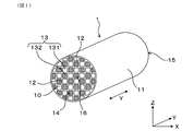
- FIG. 1 is a perspective view of the exhaust gas purification filter according to the first embodiment.
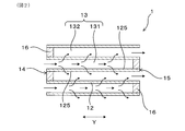
- FIG. 2 is an enlarged partial cross-sectional view of the exhaust gas purification filter in the axial direction according to the first embodiment.
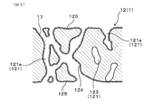
- FIG. 3 is an enlarged schematic cross-sectional view of the partition wall of the exhaust gas purification filter according to the first embodiment.
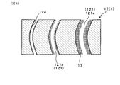
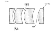
- FIG. 4 is an enlarged schematic cross-sectional view of the partition wall of the exhaust gas purification filter showing the shape of the pores in a simplified manner in the first embodiment.
- FIG. 1 is a perspective view of the exhaust gas purification filter according to the first embodiment.
- FIG. 2 is an enlarged partial cross-sectional view of the exhaust gas purification filter in the axial direction according to the first embodiment.
- FIG. 3 is an enlarged schematic cross-sectional view of the partition wall of the exhaust gas purification filter according to the first embodiment.
- FIG. 4 is an enlarged schematic cross-sectional view of the partition wall of the exhaust gas purification filter showing the shape of the pores in a simplified manner in
- FIG. 5 is an enlarged schematic cross-sectional view of the partition wall of the base material portion showing the shape of the pores in a simplified manner in the first embodiment.
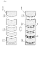
- FIG. 6 is an enlarged schematic cross-sectional view of the base material portion and the partition wall of the exhaust gas purification filter showing the shape of the pores in a simplified manner in Comparative Form 1.
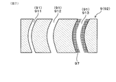
- FIG. 7 is an enlarged schematic cross-sectional view of the partition wall of the exhaust gas purification filter showing the shape of the pores in a simplified manner in Comparative Form 2.
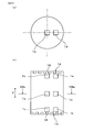
- FIG. 8A is a diagram showing the sampling position of the measurement sample in the radial direction of the exhaust gas purification filter in Experimental Example 1 (specifically, a cross-sectional view taken along the line VIIIa-VIIIa of FIG. 8B).
- FIG. 8 (b) is a diagram showing the sampling positions of the measurement samples in the axial direction and the radial direction of the exhaust gas purification filter in Experimental Example 1.
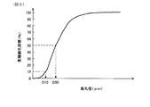
- FIG. 9 is a diagram showing an example of the pore size distribution of the exhaust gas purification filter in Experimental Example 1.
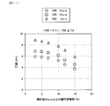
- FIG. 10 is a diagram showing the relationship between the floor area ratio of pores having a pore diameter of 50 ⁇ m or more and the collection rate in Experimental Example 1.
- FIG. 11 is a diagram showing the relationship between the floor area ratio of pores having a pore diameter of 50 ⁇ m or more and the pressure loss in Experimental Example 1.
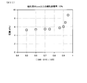
- FIG. 12 is a diagram showing the relationship between (D50-D10) / D50 in the pore size distribution and the pressure drop in Experimental Example 1.
- the exhaust gas purification filter 1 has a base material portion 10, a catalyst layer 17, and a sealing portion 16.
- the base material portion 10 is formed of ceramics such as cordierite, and has, for example, an exodermis 11, a partition wall 12, and a cell 13.
- the base material portion 10 is a portion excluding the catalyst layer 17 and the sealing portion 16, and is substantially the same as the base material having a honeycomb structure before forming the catalyst layer 17 and the sealing portion 16.
- the exodermis 11 is, for example, a cylindrical body such as a cylindrical body.
- the axial direction Y of the tubular outer skin 11 will be described below as the axial direction Y of the exhaust gas purification filter 1.
- the arrow in FIG. 2 indicates the flow of exhaust gas when the exhaust gas purification filter 1 is arranged in the path of exhaust gas such as an exhaust pipe.
- the partition wall 12 divides the inside of the exodermis 11 into a large number of cells 13.
- the partition wall 12 is also generally referred to as a cell wall.
- the partition walls 12 are provided, for example, in a grid pattern.
- the exhaust gas purification filter 1 is a porous body, and as illustrated in FIG. 3, a large number of pores 121 are formed in the partition wall 12. Therefore, the exhaust gas purification filter 1 can accumulate and collect PM contained in the exhaust gas on the surface of the partition wall 12 or in the pores 121.
- the pores 121 are sometimes called pores.
- PM is a fine particle called a particulate matter, a particulate matter, a particulate, or the like.
- the pores 121 in the present specification include the pores 121a of the filter in which the catalyst is supported and the pores 121b of the base material itself.
- the pores of the filter are appropriately referred to as “filter pores 121a”, and the pores of the base material itself are appropriately referred to as “base material pores 121b".
- the base material pores 121b have substantially the same meaning as the pores in the state where the catalyst is not supported (for example, the state before the catalyst is supported).
- the exhaust gas purification filter 1 has a large number of cells 13.
- the cell 13 is surrounded by the partition wall 12 and forms an exhaust gas flow path.
- the extension direction of the cell 13 usually coincides with the axial direction Y.
- the cell shape in the filter cross section in the direction orthogonal to the axial direction Y is, for example, a quadrangular shape, but the cell shape is not limited to this.
- the cell shape may be a polygon such as a triangle, a quadrangle, a hexagon, or a circle. Further, the cell shape may be a combination of two or more different shapes.
- the exhaust gas purification filter 1 is, for example, a columnar body such as a columnar body, and its dimensions can be changed as appropriate.
- the exhaust gas purification filter 1 has inflow side end faces 14 and outflow side end faces 15 at both ends in the axial direction Y.
- the inflow side end face 14 is the end face on the side where the exhaust gas flows in
- the outflow side end face 15 is the end face on the side where the exhaust gas flows out.
- the inflow side end face 14 and the outflow side end face 15 mean surfaces relative to each other. That is, when one of the end faces is the inflow side end face 14, the other is the outflow side end face 15.
- the inflow side end face 14 can be referred to as the first end face in the axial direction
- the outflow side end face 15 can be referred to as the second end face in the axial direction.
- the cell 13 can have a first cell 131 and a second cell 132. As illustrated in FIG. 2, the first cell 131 opens to the inflow side end face 14 and is closed by the sealing portion 16 at the outflow side end face 15. The second cell 132 opens to the outflow side end face 15, and is closed by the sealing portion 16 in the inflow side end face 14.
- the sealing portion 16 closes the inflow side end face 14 or the outflow side end face 15 of the cell 13, for example, alternately.
- the sealing portion 16 can be formed of, for example, ceramics such as cordierite, but may be made of other materials.
- the plug-shaped sealing portion 16 is formed, but the shape of the sealing portion 16 is not particularly limited as long as the inflow side end face 14 or the outflow side end face 15 can be sealed.
- the configuration is not shown, it is also possible to form the sealing portion 16 by deforming a part of the partition wall 12 on the inflow side end face 14 or the outflow side end face 15, for example. In this case, since the sealing portion 16 is formed by a part of the partition wall 12, the partition wall 12 and the sealing portion 16 are integrally and continuously formed.
- the first cell 131 and the second cell 132 alternate in the horizontal direction X orthogonal to the axial direction Y and in the vertical direction Z orthogonal to both the axial direction Y and the horizontal direction X, for example, so as to be adjacent to each other. Formed side by side. That is, when the inflow side end face 14 or the outflow side end face 15 of the exhaust gas purification filter 1 is viewed from the axial direction Y, the first cell 131 and the second cell 132 are arranged in a check pattern, for example.
- the partition wall 12 separates the first cell 131 and the second cell 132 that are adjacent to each other.
- a large number of pores 121 are formed in the partition wall 12.
- the pores 121 include communication holes that communicate between the first cell 131 and the second cell 132 that are adjacent to each other, and non-communication holes that do not communicate with each other.
- the pores 121 are simplified in two dimensions, but it is considered that most of the pores 121 intersect in three dimensions.
- the catalyst layer 17 is supported on at least the pore wall 124 of the partition wall 12.
- the pore wall 124 is a portion of the partition wall 12 facing the pore 121.
- the catalyst layer 17 is preferably formed over the entire pore wall 124. However, the catalyst layer 17 may not be formed on the pore wall 124 of the pore 121 that does not open in the cell 13.
- the catalyst layer 17 may be formed on the flow path wall 125 of the partition wall 12.
- the flow path wall 125 is a portion of the partition wall 12 facing the cell 13.
- the catalyst layer 17 contains a three-way catalyst made of a precious metal such as Pt, Rh, and Pd.
- the catalyst layer 17 may further contain alumina, a co-catalyst, and the like. Examples of the co-catalyst include ceria, zirconia, and ceria-zirconia solid solution.
- the supported amount of the catalyst layer 17 is, for example, 30 to 150 g / L.
- the average pore diameter of the partition wall 12 in the base material portion 10 in the state where the catalyst layer 17 is not formed is 15 ⁇ m or more and 22 ⁇ m or less. It is more preferably 16 ⁇ m or more and 20 ⁇ m or less, and further preferably 16 ⁇ m or more and 18 ⁇ m or less.
- the average pore diameter of the partition wall 12 in the base material portion 10 is the average pore diameter of the base material pores 121b.
- the porosity of the partition wall 12 in the base material portion 10 in the state where the catalyst layer 17 is not formed is preferably 60% or more and 70% or less, 62 It is more preferably% or more and 68% or less, and further preferably 64% or more and 67% or less.
- the porosity of the partition wall 12 in the base material portion 10 is the porosity of the base material pores 121b.
- the average pore diameter of the partition wall 12 in which the catalyst layer 17 is formed is preferably 10 ⁇ m or more and 20 ⁇ m or less, and 12 ⁇ m or more and 18 ⁇ m or less. It is more preferably 14 ⁇ m or more and 17 ⁇ m or less.
- the average pore diameter of the partition wall 12 in the state where the catalyst layer 17 is formed is the average pore diameter of the filter pores 121a.
- the porosity of the partition wall 12 in the state where the catalyst layer 17 is formed is preferably, for example, 50% or more and 60% or less, and 52% or more and 58%. It is more preferably 54% or more and 56% or less.
- the porosity in the state where the catalyst layer 17 is formed is the porosity of the filter pores 121a.
- the average pore diameter and porosity are measured based on the principle of the mercury intrusion method, and the detailed measurement method is shown in an experimental example.
- the partition wall 12 has a predetermined pore size distribution in a state where the catalyst layer 17 is formed. That is, in the present embodiment, the filter pores 121a have a predetermined pore diameter distribution. Specifically, in the pore size distribution measured by the mercury intrusion method, the pore volume ratio of the pore diameter of 50 ⁇ m or more is 10% or less, and the pore diameter D50 at which the cumulative pore volume is 50% is 10 ⁇ m or more.
- the pore diameter D10 (unit: ⁇ m) and the pore diameter D50 (unit: ⁇ m) having a cumulative pore volume of 10% satisfy the relationship of the formula I. (D50-D10) / D50 ⁇ 0.9 ... Equation I
- the pore size distribution in the state where the catalyst layer 17 is formed is good from the viewpoints of high collection rate, low pressure loss, and high purification performance.
- the catalyst layer 17 is supported on the pore walls 124 of the pores 121 having different pore diameters, and many catalyst layers 17 are formed on the pores 121 having a large pore diameter. Therefore, a sufficient amount of middle-sized pores 121 in the pore size distribution are present. As a result, the number of pores 121 having a large pore diameter that allows PM to easily slip through is reduced, and even if the catalyst layer 17 is formed in an amount necessary for purifying harmful gas components, the pores 121 having a small pore diameter are formed. Blockage is suppressed.
- the partition wall 12 of the exhaust gas purification filter 1 has a pore diameter distribution in which a large number of small to medium-sized pore diameters are present while suppressing clogging of the pores 121. Therefore, the increase in pressure loss is suppressed while maintaining the purification performance and collection rate of harmful components at a high level. As a result, the exhaust gas purification filter 1 has a high collection rate, a low pressure loss, and an excellent purification performance for harmful gas components.
- the "pore volume ratio” is the content of the pores 121, and the volume ratio of coarse pores having a pore diameter of 50 ⁇ m or more is appropriately referred to as "coarse pore volume ratio".
- the coarse pore volume ratio means the content ratio of the coarse pore volume in the total pore volume.
- the cumulative pore volume means the cumulative frequency of the pore volume in the frequency histogram of the pore diameter.
- the pore volume ratio, the pore diameter D50 at which the cumulative pore volume is 50%, and the pore diameter D10 at which the cumulative pore volume is 10% are the average of the measured values based on the principle of the mercury intrusion method for a plurality of measurement samples. It is represented by a value, and the measurement method is shown in an experimental example.
- the coarse pore floor area ratio of the exhaust gas purification filter 1 is preferably 8% or less, and more preferably 7% or less.
- the pore diameter D50 of the filter pore 121a is less than 10 ⁇ m, or when (D50-D10) /D50> 0.9, the pores with a small pore diameter increase and the pressure loss increases.
- the pore diameter D50 is preferably 12 ⁇ m or more, and more preferably 14 ⁇ m or more. From the same viewpoint, it is preferable to satisfy (D50-D10) / D50 ⁇ 0.7, and more preferably (D50-D10) / D50 ⁇ 0.6.
- the partition wall 12 in which the catalyst layer 17 is formed preferably contains 5 to 15% of pores having a pore diameter of 0.1 ⁇ m to 5 ⁇ m.
- the pore volume ratio of fine pores having a pore diameter of 0.1 ⁇ m to 5 ⁇ m is appropriately referred to as “micropore volume ratio”. That is, the fine pore volume ratio of the filter pores 121a is preferably 5 to 15%.
- the fine pore floor area ratio of the exhaust gas purification filter 1 is more preferably 6 to 14%, further preferably 7 to 14%. ..
- the lower limit of the fine pores of the partition wall 12 is 0.1 ⁇ m. This is because the catalyst layer 17 has ultrafine pores of less than 0.1 ⁇ m and is distinguished from the pores of the catalyst layer 17.
- the catalyst layer 17 is mainly formed on the pore wall 124 of the coarse base material pores 121b having a pore diameter of 50 ⁇ m or more. Specifically, it is preferable that the catalyst layer 17 is supported more on the pore wall 124 of coarse pores having a pore diameter of 50 ⁇ m or more than on the pore wall 124 of pores having a pore diameter of less than 50 ⁇ m. In this case, the high collection rate and the low voltage loss are compatible at a higher level.
- the base material portion 10 preferably contains 3 to 15% of pores 121 having a pore diameter of 50 ⁇ m or more in the partition wall 12. That is, the coarse pore volume ratio of the base material pores 121b is preferably 3 to 15%. In this case, since a sufficient amount of the catalyst layer 17 is formed in the coarse pores 121, it is possible to further improve the purification performance of harmful gas components while further suppressing the increase in pressure loss, and further collect the catalyst layer 17. The rate can be further improved. From the viewpoint of further enhancing this effect, the coarse pore volume ratio of the base material pores 121b is more preferably 5 to 10%, further preferably 6 to 8%.
- the pore volume V 1 having a pore diameter of 50 ⁇ m or more in the partition wall 12 of the base material portion 10 and the pore volume V 2 having a pore diameter of 50 ⁇ m or more in the partition wall 12 on which the catalyst layer 17 is supported satisfy the relationship of the formula II. Is preferable. That is, the coarse pore volume V 1 of the substrate pores 121b, it is preferable to satisfy the relationship of coarse pore volume V 2 Togashiki II filter pores 121a. V 2 / V 1 ⁇ 100 ⁇ 70% ⁇ ⁇ ⁇ Equation II
- the pore volume V 3 of the partition wall 12 of the base material portion 10 having a pore diameter of 0.1 ⁇ m to 5 ⁇ m and the pore volume V 4 of the partition wall 12 on which the catalyst layer 17 is supported have a pore diameter of 0.1 ⁇ m to 5 ⁇ m. It is preferable to satisfy the relationship of III. In other words, the micropore volume V 3 of the substrate pores 121b, it is preferable to satisfy the relation of the fine pore volume V 4 Togashiki III filter pores 121a. V 4 / V 3 ⁇ 100 ⁇ 200% ⁇ ⁇ ⁇ Equation III
- V 4 / V 3 ⁇ 100 ⁇ 280% is more preferable, and V 4 / V 3 ⁇ 100 ⁇ 300% is further preferable.
- V 4 / V 3 ⁇ 100 ⁇ 400% is preferable.
- the floor area ratio of the filter pores 121a and the pore diameter distributions D50 and D10 are measured by performing a mercury intrusion method on the partition wall 12 of the exhaust gas purification filter 1.
- the pore volume ratio and the pore volume of the base material pores 121b are measured, for example, by carrying out a mercury intrusion method on the partition wall 12 of the base material portion 10. The details of the measurement method by the mercury injection method will be described in Experimental Examples.
- the pore volume ratio and pore volume of the base material pores 121b can also be measured by CT scan. The CT scan is performed on the partition wall 12 on which the catalyst layer 17 is formed.
- the catalyst layer 17 and the ceramic part can be separated by performing the binarization treatment according to a predetermined threshold value. Can be separated.
- the pore volume ratio and the pore volume of the base material pores 121b can be measured with respect to the partition wall 12 in the state where the catalyst layer 17 is formed.
- the pore volume ratio and pore volume of the filter pores 121a can also be measured by CT scan.
- the exhaust gas purification filter 1 is manufactured as follows, for example. First, a clay containing a raw material for forming cordierite is prepared. The clay is prepared by adjusting talc, silica, aluminum hydroxide and the like so as to have a corderite composition, and further adding a binder, a lubricant and water and mixing them. Alumina and kaolin may be blended so as to have a cordierite composition.
- the sealing portion 16 is formed after firing the base material portion 10 or before firing. That is, it is formed by alternately sealing the end faces of the base material portion 10 of the honeycomb structure after firing or the cell 13 of the molded body of the honeycomb structure before firing using the slurry for forming the sealing portion and firing. Ru.
- the catalyst layer 17 is formed on the base material portion 10 before the formation of the sealing portion 16 or the base material portion 10 after the formation of the sealing portion 16.
- the catalyst layer 17 is formed by coating the partition wall 12 with a catalyst slurry containing a noble metal, alumina, a co-catalyst and the like.
- the catalyst layer 17 can be formed on the pore wall 124 of the partition wall 12 by performing suction or the like. Water pretreatment is performed by impregnating the base material before coating with water and removing excess water by air blow or the like, making the viscosity of the catalyst slurry slightly harder, or increasing the strength of the air blow performed after coating the catalyst slurry.
- the coarse pore volume ratio in the exhaust gas purification filter 1, D50 in the pore diameter distribution, and (D50-D10) / D50 can be adjusted in the above ranges.
- an exhaust gas purification filter 1 having a high collection rate, low pressure loss, and excellent purification performance for harmful gas components can be obtained.
- the fine pore floor area ratio of the filter pores, V 2 / V 1 ⁇ 100, V 4 / V 3 ⁇ 100, etc. are also adjusted by controlling the water pretreatment, the viscosity of the catalyst slurry, and the strength of the air blow. it can.
- Comparative Form 1 is an example of a conventional exhaust gas purification filter 7 in which pore control is not performed.
- the upper part of the arrow in FIG. 6 shows the base material portion 70 of the honeycomb structure before the catalyst layer is formed, and the lower part shows the exhaust gas purification filter after the catalyst layer is formed.
- FIG. 6 shows the shape of the pores 71 of the partition wall 72 in a simplified manner, as in FIGS. 4 and 5 in the first embodiment.
- the partition wall 72 of the base material portion 70 has a large number of various pores 71 having different pore diameters.
- each pore 71 is roughly classified into three types, a small-sized pore 711, a medium-sized pore 712, and a large-sized pore 713.
- the catalyst layer 77 When the catalyst layer 77 is formed on the partition wall 72 of the base material portion 70, a part of the pores 71 such as the small pores 711 having a small pore diameter is blocked by the catalyst layer 77. It is considered that this is because the catalyst is coated in the same manner up to the small to large size pores 711, 712, 713 regardless of the size of the pore diameter to form the catalyst layer 77. As a result, when the amount of catalyst required for purification of harmful gas components is coated, the small-sized pores 711 having high collection efficiency for PM are blocked, and the collection rate of the exhaust gas purification filter 7 is significantly reduced and the pressure loss is significantly reduced. Rise occurs.
- the exhaust gas emitted from a gasoline engine generally has a smaller PM particle size than the exhaust gas of a diesel engine.
- PM with a small particle size slips through coarse pores outside the above specified range. Therefore, a decrease in the collection rate occurs.
- Comparative form 2 is an exhaust gas purification filter 9 in which the catalyst layer 97 is formed in the large-sized pores 913 as illustrated in FIG. 7.
- the partition wall 92 of the exhaust gas purification filter 9 is formed with a large number of small to large pores 911, 912, and 913 as pores 91.
- the pores 911 and 912 other than the large size forming the catalyst layer 97 are filled with a flammable substance in advance.
- the catalyst layer is formed in the large-sized pores 913 and the flammable substance is burned off, so that the catalyst layer 97 is formed unevenly in the large-sized pores 913.
- pores 911 and 912 on which the catalyst layer is not formed are present in the partition wall 92 of the exhaust gas purification filter 9 of the comparative form 2.
- the harmful gas components such as CO, HC and NOx of the exhaust gas passing through the pores 911 and 912 are not purified. .. Therefore, the purification performance for harmful gas components is lowered.
- Example 1 the collection rate and pressure loss are comparatively evaluated for a plurality of exhaust gas purification filters 1 having different pore diameter distributions of the filter pores 121a.
- exhaust gas purification filters 1 having different pore diameter distributions specifically, Examples 1 to 14 and Comparative Examples 1 to 12 were produced.
- Each exhaust gas purification filter 1 has an average pore diameter of 10 to 20 ⁇ m and a porosity of 50 to 60%.
- the supported amount of the catalyst layer is 50 g / L.
- a measurement sample was taken from the partition wall 12 of the exhaust gas purification filter 1, and the porosity, the average pore diameter, and the pore diameter distribution were examined. The details are as follows.
- the size of the measurement sample is a substantially rectangular parallelepiped having a length of 15 mm in the axial direction Y, a thickness of 15 mm in the wall thickness direction, and a length of 20 mm orthogonal to the axial direction and the wall thickness direction.
- each measured value by the mercury porosimeter was obtained as follows, and the arithmetic mean value was used as the measurement result.
- the porosity and the average pore diameter of the partition wall 12 of each exhaust gas purification filter 1 were measured by a mercury porosimeter using the principle of the mercury intrusion method.
- a sample taken from the partition wall 12 of the base material portion 10 before the catalyst coating may be used.
- the average pore size is also called the average pore size.
- As the mercury porosimeter Autopore IV9500 manufactured by Shimadzu Corporation was used. The measurement conditions are as follows.
- the measurement sample collected as described above was stored in the measurement cell of the mercury porosimeter, and the inside of the measurement cell was depressurized. Then, mercury was introduced into the measurement cell and pressurized, and the pore diameter and the pore volume were measured from the pressure at the time of pressurization and the volume of mercury introduced into the pores of the measurement sample.
- the measurement was performed in the pressure range of 0.5 to 20000 psia.
- 0.5 psia corresponds to 0.35 ⁇ 10 -3 kg / mm 2
- 20000 psia corresponds to 14 kg / mm 2 .
- the range of the pore diameter corresponding to this pressure range is 0.01 to 420 ⁇ m.
- a contact angle of 140 ° and a surface tension of 480 dyn / cm were used as constants when calculating the pore diameter from the pressure.
- the average pore diameter is the pore diameter at an integrated value of 50% of the pore volume.
- the porosity was calculated from the following relational expression.
- the true specific gravity of cordierite is 2.52.
- Porosity (%) total pore volume / (total pore volume + 1 / true specific gravity of cordierite) x 100
- the pore volume ratio of pore diameter 50 ⁇ m or more that is, the pore volume ratio of coarse pores was determined. Further, the values of D50 and D50-D10 / D50 were obtained.
- the results of Examples 1 to 8 and Comparative Examples 1 to 10 are shown in Table 1, and the results of Examples 9 to 14, Comparative Example 11 and Comparative Example 12 are shown in Table 2.
- the exhaust gas purification filter 1 was installed in the exhaust pipe of a 2.0 L gasoline direct injection engine so that the intake air amount (Ga) was 20 g / s (steady state). Then, the exhaust gas containing PM was flowed into the exhaust gas purification filter 1. At this time, the PM concentration in the exhaust gas before flowing into the exhaust gas purification filter 1 and the PM concentration in the exhaust gas flowing out from the exhaust gas purification filter 1 were measured, and the PM collection rate was calculated.
- FIG. 10 shows the relationship between the floor area ratio of pores having a pore diameter of 50 ⁇ m or more and the collection rate of the exhaust gas purification filter 1.
- the exhaust gas purification filter 1 was installed in the exhaust pipe of a 2.0 L gasoline direct injection engine so that the intake air amount (Ga) was 100 g / s (steady state). Then, the exhaust gas containing PM was flowed into the exhaust gas purification filter 1. At this time, the pressure before and after the exhaust gas purification filter 1 was measured, and the difference was measured as a pressure loss.
- FIG. 11 shows the relationship between the floor area ratio of the exhaust gas purification filter 1 having a pore diameter of 50 ⁇ m or more and the pressure loss.
- FIG. 12 shows the relationship between (D50-D10) / D50 and the pressure loss in the pore size distribution of the exhaust gas purification filter 1.
- the tendency of the change in pressure drop changes at the floor area ratio of 10% of the large pores even when the pore diameter distribution is different. That is, when it is 10% or less, the change in pressure loss is small, and when it exceeds 10%, the pressure loss drops sharply. Further, when D50 is smaller than 10 ⁇ m, the pressure loss sharply increases.
- the floor area ratio of the pores having a pore diameter of 50 ⁇ m or more is 10% or less from the viewpoint of achieving both a high collection rate and a low voltage loss (D50-D10) /.
- D50 is 0.9 or less.
- the collection rate is preferably 55% or more, and the pressure loss is preferably 7 kPa or less.
- the exhaust gas purification filter 1 having a large pore volume ratio of 10% or less and (D50-D10) / D50 of 0.9 or less in the pore diameter distribution has a collection rate while suppressing pressure loss to 7 kPa or less. It can be as high as 55% or more.
- the partition wall 12 preferably contains 5 to 15% of fine pores having a pore diameter of 0.1 to 5 ⁇ m. That is, it is preferable that the pore volume ratio of the pore diameter of 0.1 to 5 ⁇ m is 5 to 15%.
- the low voltage loss and the high collection rate can be compatible at a higher level. The reason for this is as follows. For example, when the pore volume ratio of the pore diameter of 5 ⁇ m or less is 10%, D10 is 5 ⁇ m, so when D50 is 10 ⁇ m, (D50-D10) / D50 is 0.5, and the pressure loss is as described above. Will be low.
- the pore volume ratio having a pore diameter of 0.1 to 5 ⁇ m can be calculated from the pore diameter distribution measured using a mercury porosimeter, similarly to the pore volume ratio having a pore diameter of 50 ⁇ m or more.
- ⁇ Experimental example 2> In this example, from the viewpoint of collection rate, pressure loss, and purification performance against harmful gas components, a preferable form of the relationship between the pore size distribution of the base material portion 10 and the pore size distribution of the exhaust gas purification filter 1 is examined.
- the pore size distribution of the base material portion 10 is known by measuring the pore size distribution of the base material portion 10 before forming the catalyst layer, that is, before coating the catalyst layer.
- the pore size distribution of the exhaust gas purification filter 1 is known by measuring the pore size distribution of the filter after the catalyst layer is formed, that is, after the catalyst coating. The pore size distribution is measured in the same manner as in Experimental Example 1.
- Tables 3 and 4 show the relationship between these values and the temperature T50 when the collection rate, pressure loss, and THC concentration after the durability test reach 50%.
- THC is a general term for hydrocarbon gases, and the temperature T50 when the concentration of THC after the durability test reaches 50% was measured as follows.
- T50 A test piece having a diameter of 30 mm and L50 mm was cut out from the catalyst-coated exhaust gas purification filter 1 and subjected to thermal durability at 950 ° C. for 100 hours in an atmospheric atmosphere. T50 was measured when the temperature of the test piece after thermal durability was raised at a heating rate of 50 ° C./min using a model gas bench.
- the gas composition of the model gas bench is C 3 H 6 2700 ppmc, NO 2700 ppm, CO 0.18%, CO 2 14.8%, O 2 0.5%, H 2 O 0.49 ml /
- the SV was adjusted to 41000 / h in minutes. SV means space velocity.
- the collection rate is further increased by setting the floor area ratio of the large pores of the partition wall 12 of the base material itself to 3 to 15% and setting V 2 / V 1 ⁇ 100 to 70% or less.
- the pressure loss can be made lower.
- V 4 / V 3 ⁇ 100 is less than 200%, the purification performance of THC deteriorates sharply. From the viewpoint of further improving the purification performance, V 4 / V 3 ⁇ 100 is preferably 200% or more.
- the present disclosure is not limited to each of the above embodiments, and can be applied to various embodiments without departing from the gist thereof.
- the exhaust gas purification filter 1 is more suitable for purifying the exhaust gas discharged from the gasoline engine, but can also be used for purifying the exhaust gas discharged from the diesel engine.
Landscapes
- Chemical & Material Sciences (AREA)
- Engineering & Computer Science (AREA)
- Chemical Kinetics & Catalysis (AREA)
- Materials Engineering (AREA)
- Organic Chemistry (AREA)
- Physics & Mathematics (AREA)
- Geometry (AREA)
- Combustion & Propulsion (AREA)
- Health & Medical Sciences (AREA)
- General Engineering & Computer Science (AREA)
- Mechanical Engineering (AREA)
- Analytical Chemistry (AREA)
- Toxicology (AREA)
- Oil, Petroleum & Natural Gas (AREA)
- General Chemical & Material Sciences (AREA)
- Biomedical Technology (AREA)
- Environmental & Geological Engineering (AREA)
- Inorganic Chemistry (AREA)
- Ceramic Engineering (AREA)
- Life Sciences & Earth Sciences (AREA)
- Geology (AREA)
- Processes For Solid Components From Exhaust (AREA)
- Catalysts (AREA)
- Nanotechnology (AREA)
- Filtering Materials (AREA)
- Filtering Of Dispersed Particles In Gases (AREA)
- Exhaust Gas Treatment By Means Of Catalyst (AREA)
- Exhaust Gas After Treatment (AREA)
Priority Applications (3)
| Application Number | Priority Date | Filing Date | Title |
|---|---|---|---|
| EP20796251.5A EP3960271A4 (en) | 2019-04-26 | 2020-03-16 | Exhaust gas purification filter |
| CN202080031422.9A CN113825554A (zh) | 2019-04-26 | 2020-03-16 | 废气净化过滤器 |
| US17/451,825 US20220054978A1 (en) | 2019-04-26 | 2021-10-22 | Exhaust gas purification filter |
Applications Claiming Priority (2)
| Application Number | Priority Date | Filing Date | Title |
|---|---|---|---|
| JP2019086487A JP7097327B2 (ja) | 2019-04-26 | 2019-04-26 | 排ガス浄化フィルタ |
| JP2019-086487 | 2019-04-26 |
Related Child Applications (1)
| Application Number | Title | Priority Date | Filing Date |
|---|---|---|---|
| US17/451,825 Continuation US20220054978A1 (en) | 2019-04-26 | 2021-10-22 | Exhaust gas purification filter |
Publications (1)
| Publication Number | Publication Date |
|---|---|
| WO2020217774A1 true WO2020217774A1 (ja) | 2020-10-29 |
Family
ID=72942403
Family Applications (1)
| Application Number | Title | Priority Date | Filing Date |
|---|---|---|---|
| PCT/JP2020/011407 Ceased WO2020217774A1 (ja) | 2019-04-26 | 2020-03-16 | 排ガス浄化フィルタ |
Country Status (5)
| Country | Link |
|---|---|
| US (1) | US20220054978A1 (enExample) |
| EP (1) | EP3960271A4 (enExample) |
| JP (1) | JP7097327B2 (enExample) |
| CN (1) | CN113825554A (enExample) |
| WO (1) | WO2020217774A1 (enExample) |
Families Citing this family (1)
| Publication number | Priority date | Publication date | Assignee | Title |
|---|---|---|---|---|
| JP7481281B2 (ja) * | 2021-02-25 | 2024-05-10 | 日本碍子株式会社 | 多孔質ハニカム構造体及びその製造方法 |
Citations (3)
| Publication number | Priority date | Publication date | Assignee | Title |
|---|---|---|---|---|
| JP2003120256A (ja) * | 2001-08-06 | 2003-04-23 | Denso Corp | 排ガス浄化フィルタ |
| JP5897242B2 (ja) * | 2006-11-15 | 2016-03-30 | コーニング インコーポレイテッド | 多孔質セラミックハニカム体 |
| JP2019086487A (ja) | 2017-11-10 | 2019-06-06 | 日本電気株式会社 | コンクリート設備評価システム、解析装置、方法、およびプログラム |
Family Cites Families (7)
| Publication number | Priority date | Publication date | Assignee | Title |
|---|---|---|---|---|
| US6827754B2 (en) * | 2001-09-13 | 2004-12-07 | Hitachi Metals, Ltd. | Ceramic honeycomb filter |
| CN100458109C (zh) * | 2001-09-13 | 2009-02-04 | 日立金属株式会社 | 陶瓷蜂窝状过滤器及其制造方法 |
| JP2007144371A (ja) * | 2005-11-30 | 2007-06-14 | Toyota Motor Corp | 排ガス浄化用触媒及びその製造方法 |
| CN105392759B (zh) * | 2013-09-24 | 2018-01-26 | 日立金属株式会社 | 陶瓷蜂窝结构体及其制造方法 |
| US9968879B2 (en) * | 2015-03-24 | 2018-05-15 | Hitachi Metals, Ltd. | Ceramic honeycomb structure |
| KR102439667B1 (ko) * | 2015-03-24 | 2022-09-01 | 히타치 긴조쿠 가부시키가이샤 | 세라믹 허니컴 구조체 및 그의 제조 방법 |
| JP6934311B2 (ja) | 2016-06-02 | 2021-09-15 | 株式会社キャタラー | 排ガス浄化フィルタ |
-
2019
- 2019-04-26 JP JP2019086487A patent/JP7097327B2/ja active Active
-
2020
- 2020-03-16 WO PCT/JP2020/011407 patent/WO2020217774A1/ja not_active Ceased
- 2020-03-16 EP EP20796251.5A patent/EP3960271A4/en active Pending
- 2020-03-16 CN CN202080031422.9A patent/CN113825554A/zh active Pending
-
2021
- 2021-10-22 US US17/451,825 patent/US20220054978A1/en not_active Abandoned
Patent Citations (3)
| Publication number | Priority date | Publication date | Assignee | Title |
|---|---|---|---|---|
| JP2003120256A (ja) * | 2001-08-06 | 2003-04-23 | Denso Corp | 排ガス浄化フィルタ |
| JP5897242B2 (ja) * | 2006-11-15 | 2016-03-30 | コーニング インコーポレイテッド | 多孔質セラミックハニカム体 |
| JP2019086487A (ja) | 2017-11-10 | 2019-06-06 | 日本電気株式会社 | コンクリート設備評価システム、解析装置、方法、およびプログラム |
Non-Patent Citations (1)
| Title |
|---|
| See also references of EP3960271A4 |
Also Published As
| Publication number | Publication date |
|---|---|
| EP3960271A4 (en) | 2022-11-23 |
| JP2020182885A (ja) | 2020-11-12 |
| CN113825554A (zh) | 2021-12-21 |
| JP7097327B2 (ja) | 2022-07-07 |
| US20220054978A1 (en) | 2022-02-24 |
| EP3960271A1 (en) | 2022-03-02 |
Similar Documents
| Publication | Publication Date | Title |
|---|---|---|
| US7867598B2 (en) | Honeycomb structure and honeycomb catalytic body | |
| JP6140509B2 (ja) | ウォールフロー型排ガス浄化フィルタ | |
| JP5859752B2 (ja) | 排ガス浄化フィルタ | |
| EP2565408B1 (en) | Wall flow type exhaust gas purification filter | |
| US10415446B2 (en) | Exhaust purifying filter | |
| EP1920840A1 (en) | Honeycomb structure and honeycomb catalytic structure | |
| EP2556875B1 (en) | Exhaust gas purification filter | |
| CN111749758B (zh) | 蜂窝过滤器 | |
| JP7097327B2 (ja) | 排ガス浄化フィルタ | |
| US20220170397A1 (en) | Exhaust purification filter | |
| CN112203764B (zh) | 废气净化催化剂的制造方法 | |
| WO2020217776A1 (ja) | 排ガス浄化フィルタ | |
| WO2020031794A1 (ja) | 排ガス浄化触媒 | |
| JP6091282B2 (ja) | 触媒コートフィルタ及び触媒コートフィルタ用担体 | |
| CN112218718B (zh) | 废气净化催化剂 | |
| JP7178432B2 (ja) | 排気浄化フィルタ | |
| US20220258148A1 (en) | Plugged honeycomb structure | |
| WO2020202851A1 (ja) | 排ガス浄化フィルタ |
Legal Events
| Date | Code | Title | Description |
|---|---|---|---|
| 121 | Ep: the epo has been informed by wipo that ep was designated in this application |
Ref document number: 20796251 Country of ref document: EP Kind code of ref document: A1 |
|
| NENP | Non-entry into the national phase |
Ref country code: DE |
|
| ENP | Entry into the national phase |
Ref document number: 2020796251 Country of ref document: EP Effective date: 20211126 |