WO2020217774A1 - Exhaust gas purification filter - Google Patents
Exhaust gas purification filter Download PDFInfo
- Publication number
- WO2020217774A1 WO2020217774A1 PCT/JP2020/011407 JP2020011407W WO2020217774A1 WO 2020217774 A1 WO2020217774 A1 WO 2020217774A1 JP 2020011407 W JP2020011407 W JP 2020011407W WO 2020217774 A1 WO2020217774 A1 WO 2020217774A1
- Authority
- WO
- WIPO (PCT)
- Prior art keywords
- exhaust gas
- pores
- pore diameter
- pore
- gas purification
- Prior art date
Links
- 238000000746 purification Methods 0.000 title claims abstract description 103
- 239000011148 porous material Substances 0.000 claims abstract description 314
- 238000005192 partition Methods 0.000 claims abstract description 80
- 238000009826 distribution Methods 0.000 claims abstract description 35
- 239000003054 catalyst Substances 0.000 claims description 84
- 239000000463 material Substances 0.000 claims description 54
- 238000007789 sealing Methods 0.000 claims description 26
- 230000001186 cumulative effect Effects 0.000 claims description 12
- 239000000758 substrate Substances 0.000 abstract description 4
- 230000003197 catalytic effect Effects 0.000 abstract 4
- 239000007789 gas Substances 0.000 description 117
- 210000004027 cell Anatomy 0.000 description 33
- 238000005259 measurement Methods 0.000 description 16
- QSHDDOUJBYECFT-UHFFFAOYSA-N mercury Chemical compound [Hg] QSHDDOUJBYECFT-UHFFFAOYSA-N 0.000 description 16
- 229910052753 mercury Inorganic materials 0.000 description 16
- 230000000052 comparative effect Effects 0.000 description 14
- 238000000034 method Methods 0.000 description 9
- 239000011248 coating agent Substances 0.000 description 6
- 238000000576 coating method Methods 0.000 description 6
- 229910052878 cordierite Inorganic materials 0.000 description 6
- 238000010586 diagram Methods 0.000 description 6
- JSKIRARMQDRGJZ-UHFFFAOYSA-N dimagnesium dioxido-bis[(1-oxido-3-oxo-2,4,6,8,9-pentaoxa-1,3-disila-5,7-dialuminabicyclo[3.3.1]nonan-7-yl)oxy]silane Chemical compound [Mg++].[Mg++].[O-][Si]([O-])(O[Al]1O[Al]2O[Si](=O)O[Si]([O-])(O1)O2)O[Al]1O[Al]2O[Si](=O)O[Si]([O-])(O1)O2 JSKIRARMQDRGJZ-UHFFFAOYSA-N 0.000 description 6
- 230000007423 decrease Effects 0.000 description 5
- 238000010304 firing Methods 0.000 description 5
- 230000001965 increasing effect Effects 0.000 description 5
- 239000002002 slurry Substances 0.000 description 5
- XLYOFNOQVPJJNP-UHFFFAOYSA-N water Substances O XLYOFNOQVPJJNP-UHFFFAOYSA-N 0.000 description 5
- 239000000919 ceramic Substances 0.000 description 4
- 238000002347 injection Methods 0.000 description 4
- 239000007924 injection Substances 0.000 description 4
- 239000013618 particulate matter Substances 0.000 description 4
- 238000012360 testing method Methods 0.000 description 4
- MCMNRKCIXSYSNV-UHFFFAOYSA-N Zirconium dioxide Chemical compound O=[Zr]=O MCMNRKCIXSYSNV-UHFFFAOYSA-N 0.000 description 3
- PNEYBMLMFCGWSK-UHFFFAOYSA-N aluminium oxide Inorganic materials [O-2].[O-2].[O-2].[Al+3].[Al+3] PNEYBMLMFCGWSK-UHFFFAOYSA-N 0.000 description 3
- 239000004927 clay Substances 0.000 description 3
- 239000003426 co-catalyst Substances 0.000 description 3
- 238000002591 computed tomography Methods 0.000 description 3
- 230000000694 effects Effects 0.000 description 3
- 230000002708 enhancing effect Effects 0.000 description 3
- 230000006872 improvement Effects 0.000 description 3
- 238000000691 measurement method Methods 0.000 description 3
- 239000000203 mixture Substances 0.000 description 3
- 239000000126 substance Substances 0.000 description 3
- VYPSYNLAJGMNEJ-UHFFFAOYSA-N Silicium dioxide Chemical compound O=[Si]=O VYPSYNLAJGMNEJ-UHFFFAOYSA-N 0.000 description 2
- 230000015572 biosynthetic process Effects 0.000 description 2
- 230000008859 change Effects 0.000 description 2
- 238000004891 communication Methods 0.000 description 2
- 230000005484 gravity Effects 0.000 description 2
- 238000012986 modification Methods 0.000 description 2
- 230000004048 modification Effects 0.000 description 2
- 239000002245 particle Substances 0.000 description 2
- 230000009467 reduction Effects 0.000 description 2
- 238000005070 sampling Methods 0.000 description 2
- 239000005995 Aluminium silicate Substances 0.000 description 1
- 239000004215 Carbon black (E152) Substances 0.000 description 1
- WNROFYMDJYEPJX-UHFFFAOYSA-K aluminium hydroxide Chemical compound [OH-].[OH-].[OH-].[Al+3] WNROFYMDJYEPJX-UHFFFAOYSA-K 0.000 description 1
- 235000012211 aluminium silicate Nutrition 0.000 description 1
- 239000011230 binding agent Substances 0.000 description 1
- 229910002091 carbon monoxide Inorganic materials 0.000 description 1
- 210000002421 cell wall Anatomy 0.000 description 1
- CETPSERCERDGAM-UHFFFAOYSA-N ceric oxide Chemical compound O=[Ce]=O CETPSERCERDGAM-UHFFFAOYSA-N 0.000 description 1
- 229910000422 cerium(IV) oxide Inorganic materials 0.000 description 1
- 238000002485 combustion reaction Methods 0.000 description 1
- 238000005516 engineering process Methods 0.000 description 1
- 230000001747 exhibiting effect Effects 0.000 description 1
- 239000010419 fine particle Substances 0.000 description 1
- 231100001261 hazardous Toxicity 0.000 description 1
- 238000010438 heat treatment Methods 0.000 description 1
- 229930195733 hydrocarbon Natural products 0.000 description 1
- 150000002430 hydrocarbons Chemical class 0.000 description 1
- NLYAJNPCOHFWQQ-UHFFFAOYSA-N kaolin Chemical compound O.O.O=[Al]O[Si](=O)O[Si](=O)O[Al]=O NLYAJNPCOHFWQQ-UHFFFAOYSA-N 0.000 description 1
- 239000000314 lubricant Substances 0.000 description 1
- 238000004519 manufacturing process Methods 0.000 description 1
- 238000002156 mixing Methods 0.000 description 1
- 229910000510 noble metal Inorganic materials 0.000 description 1
- 229910052763 palladium Inorganic materials 0.000 description 1
- 229910052697 platinum Inorganic materials 0.000 description 1
- 239000010970 precious metal Substances 0.000 description 1
- 239000002994 raw material Substances 0.000 description 1
- 229910052703 rhodium Inorganic materials 0.000 description 1
- 239000000377 silicon dioxide Substances 0.000 description 1
- 238000009751 slip forming Methods 0.000 description 1
- 239000006104 solid solution Substances 0.000 description 1
- 239000000454 talc Substances 0.000 description 1
- 229910052623 talc Inorganic materials 0.000 description 1
- 229910052727 yttrium Inorganic materials 0.000 description 1
Images

Classifications
-
- B—PERFORMING OPERATIONS; TRANSPORTING
- B01—PHYSICAL OR CHEMICAL PROCESSES OR APPARATUS IN GENERAL
- B01D—SEPARATION
- B01D53/00—Separation of gases or vapours; Recovering vapours of volatile solvents from gases; Chemical or biological purification of waste gases, e.g. engine exhaust gases, smoke, fumes, flue gases, aerosols
- B01D53/34—Chemical or biological purification of waste gases
- B01D53/92—Chemical or biological purification of waste gases of engine exhaust gases
- B01D53/94—Chemical or biological purification of waste gases of engine exhaust gases by catalytic processes
- B01D53/9445—Simultaneously removing carbon monoxide, hydrocarbons or nitrogen oxides making use of three-way catalysts [TWC] or four-way-catalysts [FWC]
- B01D53/945—Simultaneously removing carbon monoxide, hydrocarbons or nitrogen oxides making use of three-way catalysts [TWC] or four-way-catalysts [FWC] characterised by a specific catalyst
-
- B—PERFORMING OPERATIONS; TRANSPORTING
- B01—PHYSICAL OR CHEMICAL PROCESSES OR APPARATUS IN GENERAL
- B01D—SEPARATION
- B01D53/00—Separation of gases or vapours; Recovering vapours of volatile solvents from gases; Chemical or biological purification of waste gases, e.g. engine exhaust gases, smoke, fumes, flue gases, aerosols
- B01D53/34—Chemical or biological purification of waste gases
- B01D53/92—Chemical or biological purification of waste gases of engine exhaust gases
- B01D53/94—Chemical or biological purification of waste gases of engine exhaust gases by catalytic processes
-
- B—PERFORMING OPERATIONS; TRANSPORTING
- B01—PHYSICAL OR CHEMICAL PROCESSES OR APPARATUS IN GENERAL
- B01D—SEPARATION
- B01D39/00—Filtering material for liquid or gaseous fluids
- B01D39/14—Other self-supporting filtering material ; Other filtering material
- B01D39/20—Other self-supporting filtering material ; Other filtering material of inorganic material, e.g. asbestos paper, metallic filtering material of non-woven wires
- B01D39/2068—Other inorganic materials, e.g. ceramics
- B01D39/2072—Other inorganic materials, e.g. ceramics the material being particulate or granular
- B01D39/2075—Other inorganic materials, e.g. ceramics the material being particulate or granular sintered or bonded by inorganic agents
-
- B—PERFORMING OPERATIONS; TRANSPORTING
- B01—PHYSICAL OR CHEMICAL PROCESSES OR APPARATUS IN GENERAL
- B01D—SEPARATION
- B01D46/00—Filters or filtering processes specially modified for separating dispersed particles from gases or vapours
- B01D46/24—Particle separators, e.g. dust precipitators, using rigid hollow filter bodies
- B01D46/2403—Particle separators, e.g. dust precipitators, using rigid hollow filter bodies characterised by the physical shape or structure of the filtering element
- B01D46/2418—Honeycomb filters
- B01D46/2425—Honeycomb filters characterized by parameters related to the physical properties of the honeycomb structure material
- B01D46/2429—Honeycomb filters characterized by parameters related to the physical properties of the honeycomb structure material of the honeycomb walls or cells
-
- B—PERFORMING OPERATIONS; TRANSPORTING
- B01—PHYSICAL OR CHEMICAL PROCESSES OR APPARATUS IN GENERAL
- B01D—SEPARATION
- B01D46/00—Filters or filtering processes specially modified for separating dispersed particles from gases or vapours
- B01D46/24—Particle separators, e.g. dust precipitators, using rigid hollow filter bodies
- B01D46/2403—Particle separators, e.g. dust precipitators, using rigid hollow filter bodies characterised by the physical shape or structure of the filtering element
- B01D46/2418—Honeycomb filters
- B01D46/2425—Honeycomb filters characterized by parameters related to the physical properties of the honeycomb structure material
- B01D46/24492—Pore diameter
-
- B—PERFORMING OPERATIONS; TRANSPORTING
- B01—PHYSICAL OR CHEMICAL PROCESSES OR APPARATUS IN GENERAL
- B01D—SEPARATION
- B01D46/00—Filters or filtering processes specially modified for separating dispersed particles from gases or vapours
- B01D46/24—Particle separators, e.g. dust precipitators, using rigid hollow filter bodies
- B01D46/2403—Particle separators, e.g. dust precipitators, using rigid hollow filter bodies characterised by the physical shape or structure of the filtering element
- B01D46/2418—Honeycomb filters
- B01D46/2498—The honeycomb filter being defined by mathematical relationships
-
- B—PERFORMING OPERATIONS; TRANSPORTING
- B01—PHYSICAL OR CHEMICAL PROCESSES OR APPARATUS IN GENERAL
- B01J—CHEMICAL OR PHYSICAL PROCESSES, e.g. CATALYSIS OR COLLOID CHEMISTRY; THEIR RELEVANT APPARATUS
- B01J23/00—Catalysts comprising metals or metal oxides or hydroxides, not provided for in group B01J21/00
- B01J23/38—Catalysts comprising metals or metal oxides or hydroxides, not provided for in group B01J21/00 of noble metals
- B01J23/40—Catalysts comprising metals or metal oxides or hydroxides, not provided for in group B01J21/00 of noble metals of the platinum group metals
-
- B01J35/56—
-
- B01J35/651—
-
- B01J35/653—
-
- B01J35/657—
-
- B—PERFORMING OPERATIONS; TRANSPORTING
- B01—PHYSICAL OR CHEMICAL PROCESSES OR APPARATUS IN GENERAL
- B01J—CHEMICAL OR PHYSICAL PROCESSES, e.g. CATALYSIS OR COLLOID CHEMISTRY; THEIR RELEVANT APPARATUS
- B01J37/00—Processes, in general, for preparing catalysts; Processes, in general, for activation of catalysts
- B01J37/02—Impregnation, coating or precipitation
- B01J37/0215—Coating
-
- F—MECHANICAL ENGINEERING; LIGHTING; HEATING; WEAPONS; BLASTING
- F01—MACHINES OR ENGINES IN GENERAL; ENGINE PLANTS IN GENERAL; STEAM ENGINES
- F01N—GAS-FLOW SILENCERS OR EXHAUST APPARATUS FOR MACHINES OR ENGINES IN GENERAL; GAS-FLOW SILENCERS OR EXHAUST APPARATUS FOR INTERNAL COMBUSTION ENGINES
- F01N3/00—Exhaust or silencing apparatus having means for purifying, rendering innocuous, or otherwise treating exhaust
- F01N3/02—Exhaust or silencing apparatus having means for purifying, rendering innocuous, or otherwise treating exhaust for cooling, or for removing solid constituents of, exhaust
- F01N3/021—Exhaust or silencing apparatus having means for purifying, rendering innocuous, or otherwise treating exhaust for cooling, or for removing solid constituents of, exhaust by means of filters
- F01N3/022—Exhaust or silencing apparatus having means for purifying, rendering innocuous, or otherwise treating exhaust for cooling, or for removing solid constituents of, exhaust by means of filters characterised by specially adapted filtering structure, e.g. honeycomb, mesh or fibrous
- F01N3/0222—Exhaust or silencing apparatus having means for purifying, rendering innocuous, or otherwise treating exhaust for cooling, or for removing solid constituents of, exhaust by means of filters characterised by specially adapted filtering structure, e.g. honeycomb, mesh or fibrous the structure being monolithic, e.g. honeycombs
-
- F—MECHANICAL ENGINEERING; LIGHTING; HEATING; WEAPONS; BLASTING
- F01—MACHINES OR ENGINES IN GENERAL; ENGINE PLANTS IN GENERAL; STEAM ENGINES
- F01N—GAS-FLOW SILENCERS OR EXHAUST APPARATUS FOR MACHINES OR ENGINES IN GENERAL; GAS-FLOW SILENCERS OR EXHAUST APPARATUS FOR INTERNAL COMBUSTION ENGINES
- F01N3/00—Exhaust or silencing apparatus having means for purifying, rendering innocuous, or otherwise treating exhaust
- F01N3/02—Exhaust or silencing apparatus having means for purifying, rendering innocuous, or otherwise treating exhaust for cooling, or for removing solid constituents of, exhaust
- F01N3/021—Exhaust or silencing apparatus having means for purifying, rendering innocuous, or otherwise treating exhaust for cooling, or for removing solid constituents of, exhaust by means of filters
- F01N3/033—Exhaust or silencing apparatus having means for purifying, rendering innocuous, or otherwise treating exhaust for cooling, or for removing solid constituents of, exhaust by means of filters in combination with other devices
- F01N3/035—Exhaust or silencing apparatus having means for purifying, rendering innocuous, or otherwise treating exhaust for cooling, or for removing solid constituents of, exhaust by means of filters in combination with other devices with catalytic reactors, e.g. catalysed diesel particulate filters
-
- F—MECHANICAL ENGINEERING; LIGHTING; HEATING; WEAPONS; BLASTING
- F01—MACHINES OR ENGINES IN GENERAL; ENGINE PLANTS IN GENERAL; STEAM ENGINES
- F01N—GAS-FLOW SILENCERS OR EXHAUST APPARATUS FOR MACHINES OR ENGINES IN GENERAL; GAS-FLOW SILENCERS OR EXHAUST APPARATUS FOR INTERNAL COMBUSTION ENGINES
- F01N3/00—Exhaust or silencing apparatus having means for purifying, rendering innocuous, or otherwise treating exhaust
- F01N3/08—Exhaust or silencing apparatus having means for purifying, rendering innocuous, or otherwise treating exhaust for rendering innocuous
- F01N3/10—Exhaust or silencing apparatus having means for purifying, rendering innocuous, or otherwise treating exhaust for rendering innocuous by thermal or catalytic conversion of noxious components of exhaust
- F01N3/24—Exhaust or silencing apparatus having means for purifying, rendering innocuous, or otherwise treating exhaust for rendering innocuous by thermal or catalytic conversion of noxious components of exhaust characterised by constructional aspects of converting apparatus
- F01N3/28—Construction of catalytic reactors
- F01N3/2803—Construction of catalytic reactors characterised by structure, by material or by manufacturing of catalyst support
-
- B—PERFORMING OPERATIONS; TRANSPORTING
- B01—PHYSICAL OR CHEMICAL PROCESSES OR APPARATUS IN GENERAL
- B01D—SEPARATION
- B01D2239/00—Aspects relating to filtering material for liquid or gaseous fluids
- B01D2239/04—Additives and treatments of the filtering material
- B01D2239/0471—Surface coating material
- B01D2239/0478—Surface coating material on a layer of the filter
-
- B—PERFORMING OPERATIONS; TRANSPORTING
- B01—PHYSICAL OR CHEMICAL PROCESSES OR APPARATUS IN GENERAL
- B01D—SEPARATION
- B01D2239/00—Aspects relating to filtering material for liquid or gaseous fluids
- B01D2239/08—Special characteristics of binders
- B01D2239/086—Binders between particles or fibres
-
- B—PERFORMING OPERATIONS; TRANSPORTING
- B01—PHYSICAL OR CHEMICAL PROCESSES OR APPARATUS IN GENERAL
- B01D—SEPARATION
- B01D2239/00—Aspects relating to filtering material for liquid or gaseous fluids
- B01D2239/10—Filtering material manufacturing
-
- B—PERFORMING OPERATIONS; TRANSPORTING
- B01—PHYSICAL OR CHEMICAL PROCESSES OR APPARATUS IN GENERAL
- B01D—SEPARATION
- B01D2239/00—Aspects relating to filtering material for liquid or gaseous fluids
- B01D2239/12—Special parameters characterising the filtering material
- B01D2239/1216—Pore size
-
- B—PERFORMING OPERATIONS; TRANSPORTING
- B01—PHYSICAL OR CHEMICAL PROCESSES OR APPARATUS IN GENERAL
- B01D—SEPARATION
- B01D2239/00—Aspects relating to filtering material for liquid or gaseous fluids
- B01D2239/12—Special parameters characterising the filtering material
- B01D2239/125—Size distribution
-
- B—PERFORMING OPERATIONS; TRANSPORTING
- B01—PHYSICAL OR CHEMICAL PROCESSES OR APPARATUS IN GENERAL
- B01D—SEPARATION
- B01D2255/00—Catalysts
- B01D2255/90—Physical characteristics of catalysts
- B01D2255/915—Catalyst supported on particulate filters
- B01D2255/9155—Wall flow filters
-
- B—PERFORMING OPERATIONS; TRANSPORTING
- B01—PHYSICAL OR CHEMICAL PROCESSES OR APPARATUS IN GENERAL
- B01D—SEPARATION
- B01D2255/00—Catalysts
- B01D2255/90—Physical characteristics of catalysts
- B01D2255/92—Dimensions
-
- B—PERFORMING OPERATIONS; TRANSPORTING
- B01—PHYSICAL OR CHEMICAL PROCESSES OR APPARATUS IN GENERAL
- B01D—SEPARATION
- B01D2255/00—Catalysts
- B01D2255/90—Physical characteristics of catalysts
- B01D2255/92—Dimensions
- B01D2255/9202—Linear dimensions
-
- B—PERFORMING OPERATIONS; TRANSPORTING
- B01—PHYSICAL OR CHEMICAL PROCESSES OR APPARATUS IN GENERAL
- B01D—SEPARATION
- B01D2255/00—Catalysts
- B01D2255/90—Physical characteristics of catalysts
- B01D2255/92—Dimensions
- B01D2255/9205—Porosity
-
- B—PERFORMING OPERATIONS; TRANSPORTING
- B01—PHYSICAL OR CHEMICAL PROCESSES OR APPARATUS IN GENERAL
- B01D—SEPARATION
- B01D2258/00—Sources of waste gases
- B01D2258/01—Engine exhaust gases
- B01D2258/012—Diesel engines and lean burn gasoline engines
-
- B—PERFORMING OPERATIONS; TRANSPORTING
- B01—PHYSICAL OR CHEMICAL PROCESSES OR APPARATUS IN GENERAL
- B01D—SEPARATION
- B01D2275/00—Filter media structures for filters specially adapted for separating dispersed particles from gases or vapours
- B01D2275/30—Porosity of filtering material
-
- B—PERFORMING OPERATIONS; TRANSPORTING
- B01—PHYSICAL OR CHEMICAL PROCESSES OR APPARATUS IN GENERAL
- B01D—SEPARATION
- B01D2279/00—Filters adapted for separating dispersed particles from gases or vapours specially modified for specific uses
- B01D2279/30—Filters adapted for separating dispersed particles from gases or vapours specially modified for specific uses for treatment of exhaust gases from IC Engines
-
- F—MECHANICAL ENGINEERING; LIGHTING; HEATING; WEAPONS; BLASTING
- F01—MACHINES OR ENGINES IN GENERAL; ENGINE PLANTS IN GENERAL; STEAM ENGINES
- F01N—GAS-FLOW SILENCERS OR EXHAUST APPARATUS FOR MACHINES OR ENGINES IN GENERAL; GAS-FLOW SILENCERS OR EXHAUST APPARATUS FOR INTERNAL COMBUSTION ENGINES
- F01N2330/00—Structure of catalyst support or particle filter
- F01N2330/06—Ceramic, e.g. monoliths
-
- F—MECHANICAL ENGINEERING; LIGHTING; HEATING; WEAPONS; BLASTING
- F01—MACHINES OR ENGINES IN GENERAL; ENGINE PLANTS IN GENERAL; STEAM ENGINES
- F01N—GAS-FLOW SILENCERS OR EXHAUST APPARATUS FOR MACHINES OR ENGINES IN GENERAL; GAS-FLOW SILENCERS OR EXHAUST APPARATUS FOR INTERNAL COMBUSTION ENGINES
- F01N2330/00—Structure of catalyst support or particle filter
- F01N2330/30—Honeycomb supports characterised by their structural details
- F01N2330/32—Honeycomb supports characterised by their structural details characterised by the shape, form or number of corrugations of plates, sheets or foils
Definitions
- the present disclosure relates to an exhaust gas purification filter having a base material portion having a honeycomb structure, a catalyst layer, and a sealing portion.
- Exhaust gas emitted from internal combustion engines such as diesel engines and gasoline engines, and heat engines such as boilers contains particulate matter called particulate matter. Particulate is hereinafter appropriately referred to as "PM".
- An exhaust gas purification filter is used to collect PM in the exhaust gas.
- the exhaust gas purification filter generally has a honeycomb-structured base material portion having a plurality of cells formed by being partitioned by a porous partition wall, and a sealing portion that alternately seals both ends of the cells.
- PM contained in the exhaust gas is collected in the pores of the partition wall, and it is required to reduce the pressure loss while increasing the collection rate of PM.
- the PM collection rate is hereinafter appropriately referred to as “collection rate”
- the pressure loss is hereinafter appropriately referred to as "pressure loss”.
- pressure loss In order to reduce the pressure loss, it is effective to increase the porosity of the partition wall, but if the porosity is increased, the collection rate tends to decrease.
- Patent Document 1 by forming a coat layer containing a catalyst in a state where pores having a pore diameter of 10 ⁇ m or less are previously closed, a coat layer is formed biased to pores having a pore diameter exceeding 10 ⁇ m.
- the technology to be used is disclosed.
- Patent Document 1 In the technique of Patent Document 1, the number of pores on which the catalyst is not supported increases. As a result, the purification rate for harmful gas components tends to deteriorate. In recent years, there have been increasing demands for collection rate, pressure loss, and purification rate of harmful gas components, and further improvement is required.
- the present disclosure is intended to provide an exhaust gas purification filter having a high collection rate, low pressure loss, and excellent purification performance for harmful gas components.
- One aspect of the present disclosure is a honeycomb-structured base material portion having a porous partition wall and a plurality of cells partitioned by the partition wall and forming an exhaust gas flow path.
- the catalyst layer supported on the pore wall in the partition wall of the base material portion and A sealing portion that alternately closes the inflow side end face or the outflow side end face of the exhaust gas in the cell is provided.
- the partition wall on which the catalyst layer is supported contains 10% or less of pores having a pore diameter of 50 ⁇ m or more.
- the pore diameter D50 at which the cumulative pore volume is 50% is 10 ⁇ m or more
- D50 is an exhaust gas purification filter that satisfies the relationship of the following formula I. (D50-D10) / D50 ⁇ 0.9 ... Equation I
- the exhaust gas purification filter has a base material portion, a catalyst layer, and a sealing portion.
- the catalyst layer is supported at least on the pore wall of the partition wall.
- the partition wall has pores having a pore diameter of 50 ⁇ m or more in a state where the catalyst layer is supported, having a pore diameter of 50 ⁇ m or more and having a pore diameter distribution in which the pore diameters D50 and D10 satisfy the predetermined relationship.
- An exhaust gas purification filter having such a configuration has low pressure loss, high collection rate, and excellent purification performance against harmful gases even when the catalyst is sufficiently supported.
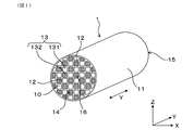
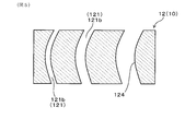
- FIG. 1 is a perspective view of the exhaust gas purification filter according to the first embodiment.
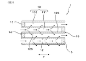
- FIG. 2 is an enlarged partial cross-sectional view of the exhaust gas purification filter in the axial direction according to the first embodiment.
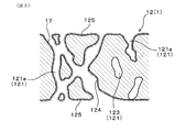
- FIG. 3 is an enlarged schematic cross-sectional view of the partition wall of the exhaust gas purification filter according to the first embodiment.
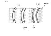
- FIG. 4 is an enlarged schematic cross-sectional view of the partition wall of the exhaust gas purification filter showing the shape of the pores in a simplified manner in the first embodiment.
- FIG. 1 is a perspective view of the exhaust gas purification filter according to the first embodiment.
- FIG. 2 is an enlarged partial cross-sectional view of the exhaust gas purification filter in the axial direction according to the first embodiment.
- FIG. 3 is an enlarged schematic cross-sectional view of the partition wall of the exhaust gas purification filter according to the first embodiment.
- FIG. 4 is an enlarged schematic cross-sectional view of the partition wall of the exhaust gas purification filter showing the shape of the pores in a simplified manner in
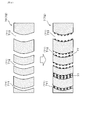
- FIG. 5 is an enlarged schematic cross-sectional view of the partition wall of the base material portion showing the shape of the pores in a simplified manner in the first embodiment.
- FIG. 6 is an enlarged schematic cross-sectional view of the base material portion and the partition wall of the exhaust gas purification filter showing the shape of the pores in a simplified manner in Comparative Form 1.
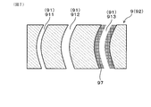
- FIG. 7 is an enlarged schematic cross-sectional view of the partition wall of the exhaust gas purification filter showing the shape of the pores in a simplified manner in Comparative Form 2.
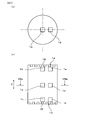
- FIG. 8A is a diagram showing the sampling position of the measurement sample in the radial direction of the exhaust gas purification filter in Experimental Example 1 (specifically, a cross-sectional view taken along the line VIIIa-VIIIa of FIG. 8B).
- FIG. 8 (b) is a diagram showing the sampling positions of the measurement samples in the axial direction and the radial direction of the exhaust gas purification filter in Experimental Example 1.
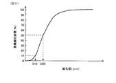
- FIG. 9 is a diagram showing an example of the pore size distribution of the exhaust gas purification filter in Experimental Example 1.
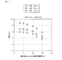
- FIG. 10 is a diagram showing the relationship between the floor area ratio of pores having a pore diameter of 50 ⁇ m or more and the collection rate in Experimental Example 1.
- FIG. 11 is a diagram showing the relationship between the floor area ratio of pores having a pore diameter of 50 ⁇ m or more and the pressure loss in Experimental Example 1.
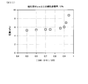
- FIG. 12 is a diagram showing the relationship between (D50-D10) / D50 in the pore size distribution and the pressure drop in Experimental Example 1.
- the exhaust gas purification filter 1 has a base material portion 10, a catalyst layer 17, and a sealing portion 16.
- the base material portion 10 is formed of ceramics such as cordierite, and has, for example, an exodermis 11, a partition wall 12, and a cell 13.
- the base material portion 10 is a portion excluding the catalyst layer 17 and the sealing portion 16, and is substantially the same as the base material having a honeycomb structure before forming the catalyst layer 17 and the sealing portion 16.
- the exodermis 11 is, for example, a cylindrical body such as a cylindrical body.
- the axial direction Y of the tubular outer skin 11 will be described below as the axial direction Y of the exhaust gas purification filter 1.
- the arrow in FIG. 2 indicates the flow of exhaust gas when the exhaust gas purification filter 1 is arranged in the path of exhaust gas such as an exhaust pipe.
- the partition wall 12 divides the inside of the exodermis 11 into a large number of cells 13.
- the partition wall 12 is also generally referred to as a cell wall.
- the partition walls 12 are provided, for example, in a grid pattern.
- the exhaust gas purification filter 1 is a porous body, and as illustrated in FIG. 3, a large number of pores 121 are formed in the partition wall 12. Therefore, the exhaust gas purification filter 1 can accumulate and collect PM contained in the exhaust gas on the surface of the partition wall 12 or in the pores 121.
- the pores 121 are sometimes called pores.
- PM is a fine particle called a particulate matter, a particulate matter, a particulate, or the like.
- the pores 121 in the present specification include the pores 121a of the filter in which the catalyst is supported and the pores 121b of the base material itself.
- the pores of the filter are appropriately referred to as “filter pores 121a”, and the pores of the base material itself are appropriately referred to as “base material pores 121b".
- the base material pores 121b have substantially the same meaning as the pores in the state where the catalyst is not supported (for example, the state before the catalyst is supported).
- the exhaust gas purification filter 1 has a large number of cells 13.
- the cell 13 is surrounded by the partition wall 12 and forms an exhaust gas flow path.
- the extension direction of the cell 13 usually coincides with the axial direction Y.
- the cell shape in the filter cross section in the direction orthogonal to the axial direction Y is, for example, a quadrangular shape, but the cell shape is not limited to this.
- the cell shape may be a polygon such as a triangle, a quadrangle, a hexagon, or a circle. Further, the cell shape may be a combination of two or more different shapes.
- the exhaust gas purification filter 1 is, for example, a columnar body such as a columnar body, and its dimensions can be changed as appropriate.
- the exhaust gas purification filter 1 has inflow side end faces 14 and outflow side end faces 15 at both ends in the axial direction Y.
- the inflow side end face 14 is the end face on the side where the exhaust gas flows in
- the outflow side end face 15 is the end face on the side where the exhaust gas flows out.
- the inflow side end face 14 and the outflow side end face 15 mean surfaces relative to each other. That is, when one of the end faces is the inflow side end face 14, the other is the outflow side end face 15.
- the inflow side end face 14 can be referred to as the first end face in the axial direction
- the outflow side end face 15 can be referred to as the second end face in the axial direction.
- the cell 13 can have a first cell 131 and a second cell 132. As illustrated in FIG. 2, the first cell 131 opens to the inflow side end face 14 and is closed by the sealing portion 16 at the outflow side end face 15. The second cell 132 opens to the outflow side end face 15, and is closed by the sealing portion 16 in the inflow side end face 14.
- the sealing portion 16 closes the inflow side end face 14 or the outflow side end face 15 of the cell 13, for example, alternately.
- the sealing portion 16 can be formed of, for example, ceramics such as cordierite, but may be made of other materials.
- the plug-shaped sealing portion 16 is formed, but the shape of the sealing portion 16 is not particularly limited as long as the inflow side end face 14 or the outflow side end face 15 can be sealed.
- the configuration is not shown, it is also possible to form the sealing portion 16 by deforming a part of the partition wall 12 on the inflow side end face 14 or the outflow side end face 15, for example. In this case, since the sealing portion 16 is formed by a part of the partition wall 12, the partition wall 12 and the sealing portion 16 are integrally and continuously formed.
- the first cell 131 and the second cell 132 alternate in the horizontal direction X orthogonal to the axial direction Y and in the vertical direction Z orthogonal to both the axial direction Y and the horizontal direction X, for example, so as to be adjacent to each other. Formed side by side. That is, when the inflow side end face 14 or the outflow side end face 15 of the exhaust gas purification filter 1 is viewed from the axial direction Y, the first cell 131 and the second cell 132 are arranged in a check pattern, for example.
- the partition wall 12 separates the first cell 131 and the second cell 132 that are adjacent to each other.
- a large number of pores 121 are formed in the partition wall 12.
- the pores 121 include communication holes that communicate between the first cell 131 and the second cell 132 that are adjacent to each other, and non-communication holes that do not communicate with each other.
- the pores 121 are simplified in two dimensions, but it is considered that most of the pores 121 intersect in three dimensions.
- the catalyst layer 17 is supported on at least the pore wall 124 of the partition wall 12.
- the pore wall 124 is a portion of the partition wall 12 facing the pore 121.
- the catalyst layer 17 is preferably formed over the entire pore wall 124. However, the catalyst layer 17 may not be formed on the pore wall 124 of the pore 121 that does not open in the cell 13.
- the catalyst layer 17 may be formed on the flow path wall 125 of the partition wall 12.
- the flow path wall 125 is a portion of the partition wall 12 facing the cell 13.
- the catalyst layer 17 contains a three-way catalyst made of a precious metal such as Pt, Rh, and Pd.
- the catalyst layer 17 may further contain alumina, a co-catalyst, and the like. Examples of the co-catalyst include ceria, zirconia, and ceria-zirconia solid solution.
- the supported amount of the catalyst layer 17 is, for example, 30 to 150 g / L.
- the average pore diameter of the partition wall 12 in the base material portion 10 in the state where the catalyst layer 17 is not formed is 15 ⁇ m or more and 22 ⁇ m or less. It is more preferably 16 ⁇ m or more and 20 ⁇ m or less, and further preferably 16 ⁇ m or more and 18 ⁇ m or less.
- the average pore diameter of the partition wall 12 in the base material portion 10 is the average pore diameter of the base material pores 121b.
- the porosity of the partition wall 12 in the base material portion 10 in the state where the catalyst layer 17 is not formed is preferably 60% or more and 70% or less, 62 It is more preferably% or more and 68% or less, and further preferably 64% or more and 67% or less.
- the porosity of the partition wall 12 in the base material portion 10 is the porosity of the base material pores 121b.
- the average pore diameter of the partition wall 12 in which the catalyst layer 17 is formed is preferably 10 ⁇ m or more and 20 ⁇ m or less, and 12 ⁇ m or more and 18 ⁇ m or less. It is more preferably 14 ⁇ m or more and 17 ⁇ m or less.
- the average pore diameter of the partition wall 12 in the state where the catalyst layer 17 is formed is the average pore diameter of the filter pores 121a.
- the porosity of the partition wall 12 in the state where the catalyst layer 17 is formed is preferably, for example, 50% or more and 60% or less, and 52% or more and 58%. It is more preferably 54% or more and 56% or less.
- the porosity in the state where the catalyst layer 17 is formed is the porosity of the filter pores 121a.
- the average pore diameter and porosity are measured based on the principle of the mercury intrusion method, and the detailed measurement method is shown in an experimental example.
- the partition wall 12 has a predetermined pore size distribution in a state where the catalyst layer 17 is formed. That is, in the present embodiment, the filter pores 121a have a predetermined pore diameter distribution. Specifically, in the pore size distribution measured by the mercury intrusion method, the pore volume ratio of the pore diameter of 50 ⁇ m or more is 10% or less, and the pore diameter D50 at which the cumulative pore volume is 50% is 10 ⁇ m or more.
- the pore diameter D10 (unit: ⁇ m) and the pore diameter D50 (unit: ⁇ m) having a cumulative pore volume of 10% satisfy the relationship of the formula I. (D50-D10) / D50 ⁇ 0.9 ... Equation I
- the pore size distribution in the state where the catalyst layer 17 is formed is good from the viewpoints of high collection rate, low pressure loss, and high purification performance.
- the catalyst layer 17 is supported on the pore walls 124 of the pores 121 having different pore diameters, and many catalyst layers 17 are formed on the pores 121 having a large pore diameter. Therefore, a sufficient amount of middle-sized pores 121 in the pore size distribution are present. As a result, the number of pores 121 having a large pore diameter that allows PM to easily slip through is reduced, and even if the catalyst layer 17 is formed in an amount necessary for purifying harmful gas components, the pores 121 having a small pore diameter are formed. Blockage is suppressed.
- the partition wall 12 of the exhaust gas purification filter 1 has a pore diameter distribution in which a large number of small to medium-sized pore diameters are present while suppressing clogging of the pores 121. Therefore, the increase in pressure loss is suppressed while maintaining the purification performance and collection rate of harmful components at a high level. As a result, the exhaust gas purification filter 1 has a high collection rate, a low pressure loss, and an excellent purification performance for harmful gas components.
- the "pore volume ratio” is the content of the pores 121, and the volume ratio of coarse pores having a pore diameter of 50 ⁇ m or more is appropriately referred to as "coarse pore volume ratio".
- the coarse pore volume ratio means the content ratio of the coarse pore volume in the total pore volume.
- the cumulative pore volume means the cumulative frequency of the pore volume in the frequency histogram of the pore diameter.
- the pore volume ratio, the pore diameter D50 at which the cumulative pore volume is 50%, and the pore diameter D10 at which the cumulative pore volume is 10% are the average of the measured values based on the principle of the mercury intrusion method for a plurality of measurement samples. It is represented by a value, and the measurement method is shown in an experimental example.
- the coarse pore floor area ratio of the exhaust gas purification filter 1 is preferably 8% or less, and more preferably 7% or less.
- the pore diameter D50 of the filter pore 121a is less than 10 ⁇ m, or when (D50-D10) /D50> 0.9, the pores with a small pore diameter increase and the pressure loss increases.
- the pore diameter D50 is preferably 12 ⁇ m or more, and more preferably 14 ⁇ m or more. From the same viewpoint, it is preferable to satisfy (D50-D10) / D50 ⁇ 0.7, and more preferably (D50-D10) / D50 ⁇ 0.6.
- the partition wall 12 in which the catalyst layer 17 is formed preferably contains 5 to 15% of pores having a pore diameter of 0.1 ⁇ m to 5 ⁇ m.
- the pore volume ratio of fine pores having a pore diameter of 0.1 ⁇ m to 5 ⁇ m is appropriately referred to as “micropore volume ratio”. That is, the fine pore volume ratio of the filter pores 121a is preferably 5 to 15%.
- the fine pore floor area ratio of the exhaust gas purification filter 1 is more preferably 6 to 14%, further preferably 7 to 14%. ..
- the lower limit of the fine pores of the partition wall 12 is 0.1 ⁇ m. This is because the catalyst layer 17 has ultrafine pores of less than 0.1 ⁇ m and is distinguished from the pores of the catalyst layer 17.
- the catalyst layer 17 is mainly formed on the pore wall 124 of the coarse base material pores 121b having a pore diameter of 50 ⁇ m or more. Specifically, it is preferable that the catalyst layer 17 is supported more on the pore wall 124 of coarse pores having a pore diameter of 50 ⁇ m or more than on the pore wall 124 of pores having a pore diameter of less than 50 ⁇ m. In this case, the high collection rate and the low voltage loss are compatible at a higher level.
- the base material portion 10 preferably contains 3 to 15% of pores 121 having a pore diameter of 50 ⁇ m or more in the partition wall 12. That is, the coarse pore volume ratio of the base material pores 121b is preferably 3 to 15%. In this case, since a sufficient amount of the catalyst layer 17 is formed in the coarse pores 121, it is possible to further improve the purification performance of harmful gas components while further suppressing the increase in pressure loss, and further collect the catalyst layer 17. The rate can be further improved. From the viewpoint of further enhancing this effect, the coarse pore volume ratio of the base material pores 121b is more preferably 5 to 10%, further preferably 6 to 8%.
- the pore volume V 1 having a pore diameter of 50 ⁇ m or more in the partition wall 12 of the base material portion 10 and the pore volume V 2 having a pore diameter of 50 ⁇ m or more in the partition wall 12 on which the catalyst layer 17 is supported satisfy the relationship of the formula II. Is preferable. That is, the coarse pore volume V 1 of the substrate pores 121b, it is preferable to satisfy the relationship of coarse pore volume V 2 Togashiki II filter pores 121a. V 2 / V 1 ⁇ 100 ⁇ 70% ⁇ ⁇ ⁇ Equation II
- the pore volume V 3 of the partition wall 12 of the base material portion 10 having a pore diameter of 0.1 ⁇ m to 5 ⁇ m and the pore volume V 4 of the partition wall 12 on which the catalyst layer 17 is supported have a pore diameter of 0.1 ⁇ m to 5 ⁇ m. It is preferable to satisfy the relationship of III. In other words, the micropore volume V 3 of the substrate pores 121b, it is preferable to satisfy the relation of the fine pore volume V 4 Togashiki III filter pores 121a. V 4 / V 3 ⁇ 100 ⁇ 200% ⁇ ⁇ ⁇ Equation III
- V 4 / V 3 ⁇ 100 ⁇ 280% is more preferable, and V 4 / V 3 ⁇ 100 ⁇ 300% is further preferable.
- V 4 / V 3 ⁇ 100 ⁇ 400% is preferable.
- the floor area ratio of the filter pores 121a and the pore diameter distributions D50 and D10 are measured by performing a mercury intrusion method on the partition wall 12 of the exhaust gas purification filter 1.
- the pore volume ratio and the pore volume of the base material pores 121b are measured, for example, by carrying out a mercury intrusion method on the partition wall 12 of the base material portion 10. The details of the measurement method by the mercury injection method will be described in Experimental Examples.
- the pore volume ratio and pore volume of the base material pores 121b can also be measured by CT scan. The CT scan is performed on the partition wall 12 on which the catalyst layer 17 is formed.
- the catalyst layer 17 and the ceramic part can be separated by performing the binarization treatment according to a predetermined threshold value. Can be separated.
- the pore volume ratio and the pore volume of the base material pores 121b can be measured with respect to the partition wall 12 in the state where the catalyst layer 17 is formed.
- the pore volume ratio and pore volume of the filter pores 121a can also be measured by CT scan.
- the exhaust gas purification filter 1 is manufactured as follows, for example. First, a clay containing a raw material for forming cordierite is prepared. The clay is prepared by adjusting talc, silica, aluminum hydroxide and the like so as to have a corderite composition, and further adding a binder, a lubricant and water and mixing them. Alumina and kaolin may be blended so as to have a cordierite composition.
- the sealing portion 16 is formed after firing the base material portion 10 or before firing. That is, it is formed by alternately sealing the end faces of the base material portion 10 of the honeycomb structure after firing or the cell 13 of the molded body of the honeycomb structure before firing using the slurry for forming the sealing portion and firing. Ru.
- the catalyst layer 17 is formed on the base material portion 10 before the formation of the sealing portion 16 or the base material portion 10 after the formation of the sealing portion 16.
- the catalyst layer 17 is formed by coating the partition wall 12 with a catalyst slurry containing a noble metal, alumina, a co-catalyst and the like.
- the catalyst layer 17 can be formed on the pore wall 124 of the partition wall 12 by performing suction or the like. Water pretreatment is performed by impregnating the base material before coating with water and removing excess water by air blow or the like, making the viscosity of the catalyst slurry slightly harder, or increasing the strength of the air blow performed after coating the catalyst slurry.
- the coarse pore volume ratio in the exhaust gas purification filter 1, D50 in the pore diameter distribution, and (D50-D10) / D50 can be adjusted in the above ranges.
- an exhaust gas purification filter 1 having a high collection rate, low pressure loss, and excellent purification performance for harmful gas components can be obtained.
- the fine pore floor area ratio of the filter pores, V 2 / V 1 ⁇ 100, V 4 / V 3 ⁇ 100, etc. are also adjusted by controlling the water pretreatment, the viscosity of the catalyst slurry, and the strength of the air blow. it can.
- Comparative Form 1 is an example of a conventional exhaust gas purification filter 7 in which pore control is not performed.
- the upper part of the arrow in FIG. 6 shows the base material portion 70 of the honeycomb structure before the catalyst layer is formed, and the lower part shows the exhaust gas purification filter after the catalyst layer is formed.
- FIG. 6 shows the shape of the pores 71 of the partition wall 72 in a simplified manner, as in FIGS. 4 and 5 in the first embodiment.
- the partition wall 72 of the base material portion 70 has a large number of various pores 71 having different pore diameters.
- each pore 71 is roughly classified into three types, a small-sized pore 711, a medium-sized pore 712, and a large-sized pore 713.
- the catalyst layer 77 When the catalyst layer 77 is formed on the partition wall 72 of the base material portion 70, a part of the pores 71 such as the small pores 711 having a small pore diameter is blocked by the catalyst layer 77. It is considered that this is because the catalyst is coated in the same manner up to the small to large size pores 711, 712, 713 regardless of the size of the pore diameter to form the catalyst layer 77. As a result, when the amount of catalyst required for purification of harmful gas components is coated, the small-sized pores 711 having high collection efficiency for PM are blocked, and the collection rate of the exhaust gas purification filter 7 is significantly reduced and the pressure loss is significantly reduced. Rise occurs.
- the exhaust gas emitted from a gasoline engine generally has a smaller PM particle size than the exhaust gas of a diesel engine.
- PM with a small particle size slips through coarse pores outside the above specified range. Therefore, a decrease in the collection rate occurs.
- Comparative form 2 is an exhaust gas purification filter 9 in which the catalyst layer 97 is formed in the large-sized pores 913 as illustrated in FIG. 7.
- the partition wall 92 of the exhaust gas purification filter 9 is formed with a large number of small to large pores 911, 912, and 913 as pores 91.
- the pores 911 and 912 other than the large size forming the catalyst layer 97 are filled with a flammable substance in advance.
- the catalyst layer is formed in the large-sized pores 913 and the flammable substance is burned off, so that the catalyst layer 97 is formed unevenly in the large-sized pores 913.
- pores 911 and 912 on which the catalyst layer is not formed are present in the partition wall 92 of the exhaust gas purification filter 9 of the comparative form 2.
- the harmful gas components such as CO, HC and NOx of the exhaust gas passing through the pores 911 and 912 are not purified. .. Therefore, the purification performance for harmful gas components is lowered.
- Example 1 the collection rate and pressure loss are comparatively evaluated for a plurality of exhaust gas purification filters 1 having different pore diameter distributions of the filter pores 121a.
- exhaust gas purification filters 1 having different pore diameter distributions specifically, Examples 1 to 14 and Comparative Examples 1 to 12 were produced.
- Each exhaust gas purification filter 1 has an average pore diameter of 10 to 20 ⁇ m and a porosity of 50 to 60%.
- the supported amount of the catalyst layer is 50 g / L.
- a measurement sample was taken from the partition wall 12 of the exhaust gas purification filter 1, and the porosity, the average pore diameter, and the pore diameter distribution were examined. The details are as follows.
- the size of the measurement sample is a substantially rectangular parallelepiped having a length of 15 mm in the axial direction Y, a thickness of 15 mm in the wall thickness direction, and a length of 20 mm orthogonal to the axial direction and the wall thickness direction.
- each measured value by the mercury porosimeter was obtained as follows, and the arithmetic mean value was used as the measurement result.
- the porosity and the average pore diameter of the partition wall 12 of each exhaust gas purification filter 1 were measured by a mercury porosimeter using the principle of the mercury intrusion method.
- a sample taken from the partition wall 12 of the base material portion 10 before the catalyst coating may be used.
- the average pore size is also called the average pore size.
- As the mercury porosimeter Autopore IV9500 manufactured by Shimadzu Corporation was used. The measurement conditions are as follows.
- the measurement sample collected as described above was stored in the measurement cell of the mercury porosimeter, and the inside of the measurement cell was depressurized. Then, mercury was introduced into the measurement cell and pressurized, and the pore diameter and the pore volume were measured from the pressure at the time of pressurization and the volume of mercury introduced into the pores of the measurement sample.
- the measurement was performed in the pressure range of 0.5 to 20000 psia.
- 0.5 psia corresponds to 0.35 ⁇ 10 -3 kg / mm 2
- 20000 psia corresponds to 14 kg / mm 2 .
- the range of the pore diameter corresponding to this pressure range is 0.01 to 420 ⁇ m.
- a contact angle of 140 ° and a surface tension of 480 dyn / cm were used as constants when calculating the pore diameter from the pressure.
- the average pore diameter is the pore diameter at an integrated value of 50% of the pore volume.
- the porosity was calculated from the following relational expression.
- the true specific gravity of cordierite is 2.52.
- Porosity (%) total pore volume / (total pore volume + 1 / true specific gravity of cordierite) x 100
- the pore volume ratio of pore diameter 50 ⁇ m or more that is, the pore volume ratio of coarse pores was determined. Further, the values of D50 and D50-D10 / D50 were obtained.
- the results of Examples 1 to 8 and Comparative Examples 1 to 10 are shown in Table 1, and the results of Examples 9 to 14, Comparative Example 11 and Comparative Example 12 are shown in Table 2.
- the exhaust gas purification filter 1 was installed in the exhaust pipe of a 2.0 L gasoline direct injection engine so that the intake air amount (Ga) was 20 g / s (steady state). Then, the exhaust gas containing PM was flowed into the exhaust gas purification filter 1. At this time, the PM concentration in the exhaust gas before flowing into the exhaust gas purification filter 1 and the PM concentration in the exhaust gas flowing out from the exhaust gas purification filter 1 were measured, and the PM collection rate was calculated.
- FIG. 10 shows the relationship between the floor area ratio of pores having a pore diameter of 50 ⁇ m or more and the collection rate of the exhaust gas purification filter 1.
- the exhaust gas purification filter 1 was installed in the exhaust pipe of a 2.0 L gasoline direct injection engine so that the intake air amount (Ga) was 100 g / s (steady state). Then, the exhaust gas containing PM was flowed into the exhaust gas purification filter 1. At this time, the pressure before and after the exhaust gas purification filter 1 was measured, and the difference was measured as a pressure loss.
- FIG. 11 shows the relationship between the floor area ratio of the exhaust gas purification filter 1 having a pore diameter of 50 ⁇ m or more and the pressure loss.
- FIG. 12 shows the relationship between (D50-D10) / D50 and the pressure loss in the pore size distribution of the exhaust gas purification filter 1.
- the tendency of the change in pressure drop changes at the floor area ratio of 10% of the large pores even when the pore diameter distribution is different. That is, when it is 10% or less, the change in pressure loss is small, and when it exceeds 10%, the pressure loss drops sharply. Further, when D50 is smaller than 10 ⁇ m, the pressure loss sharply increases.
- the floor area ratio of the pores having a pore diameter of 50 ⁇ m or more is 10% or less from the viewpoint of achieving both a high collection rate and a low voltage loss (D50-D10) /.
- D50 is 0.9 or less.
- the collection rate is preferably 55% or more, and the pressure loss is preferably 7 kPa or less.
- the exhaust gas purification filter 1 having a large pore volume ratio of 10% or less and (D50-D10) / D50 of 0.9 or less in the pore diameter distribution has a collection rate while suppressing pressure loss to 7 kPa or less. It can be as high as 55% or more.
- the partition wall 12 preferably contains 5 to 15% of fine pores having a pore diameter of 0.1 to 5 ⁇ m. That is, it is preferable that the pore volume ratio of the pore diameter of 0.1 to 5 ⁇ m is 5 to 15%.
- the low voltage loss and the high collection rate can be compatible at a higher level. The reason for this is as follows. For example, when the pore volume ratio of the pore diameter of 5 ⁇ m or less is 10%, D10 is 5 ⁇ m, so when D50 is 10 ⁇ m, (D50-D10) / D50 is 0.5, and the pressure loss is as described above. Will be low.
- the pore volume ratio having a pore diameter of 0.1 to 5 ⁇ m can be calculated from the pore diameter distribution measured using a mercury porosimeter, similarly to the pore volume ratio having a pore diameter of 50 ⁇ m or more.
- ⁇ Experimental example 2> In this example, from the viewpoint of collection rate, pressure loss, and purification performance against harmful gas components, a preferable form of the relationship between the pore size distribution of the base material portion 10 and the pore size distribution of the exhaust gas purification filter 1 is examined.
- the pore size distribution of the base material portion 10 is known by measuring the pore size distribution of the base material portion 10 before forming the catalyst layer, that is, before coating the catalyst layer.
- the pore size distribution of the exhaust gas purification filter 1 is known by measuring the pore size distribution of the filter after the catalyst layer is formed, that is, after the catalyst coating. The pore size distribution is measured in the same manner as in Experimental Example 1.
- Tables 3 and 4 show the relationship between these values and the temperature T50 when the collection rate, pressure loss, and THC concentration after the durability test reach 50%.
- THC is a general term for hydrocarbon gases, and the temperature T50 when the concentration of THC after the durability test reaches 50% was measured as follows.
- T50 A test piece having a diameter of 30 mm and L50 mm was cut out from the catalyst-coated exhaust gas purification filter 1 and subjected to thermal durability at 950 ° C. for 100 hours in an atmospheric atmosphere. T50 was measured when the temperature of the test piece after thermal durability was raised at a heating rate of 50 ° C./min using a model gas bench.
- the gas composition of the model gas bench is C 3 H 6 2700 ppmc, NO 2700 ppm, CO 0.18%, CO 2 14.8%, O 2 0.5%, H 2 O 0.49 ml /
- the SV was adjusted to 41000 / h in minutes. SV means space velocity.
- the collection rate is further increased by setting the floor area ratio of the large pores of the partition wall 12 of the base material itself to 3 to 15% and setting V 2 / V 1 ⁇ 100 to 70% or less.
- the pressure loss can be made lower.
- V 4 / V 3 ⁇ 100 is less than 200%, the purification performance of THC deteriorates sharply. From the viewpoint of further improving the purification performance, V 4 / V 3 ⁇ 100 is preferably 200% or more.
- the present disclosure is not limited to each of the above embodiments, and can be applied to various embodiments without departing from the gist thereof.
- the exhaust gas purification filter 1 is more suitable for purifying the exhaust gas discharged from the gasoline engine, but can also be used for purifying the exhaust gas discharged from the diesel engine.
Abstract
Provided is an exhaust gas purification filter comprising a substrate portion, a catalytic layer (17), and a seal portion. The substrate portion has a porous partition (12). The catalytic layer (17) is supported in a pore wall (124) of the partition (12). The partition (12) supporting the catalytic layer (17) contains 10% or less of pores (121) with a pore size of 50 μm or greater. In the pore size distribution for the partition (12) supporting the catalytic layer (17), pore size D50, which is 50% of the accumulative pore volume, is 10 μm or greater. The relationship between pore size D10, which is 10% of the accumulative pore volume, and the pore size D50 satisfies formula I. Formula I: (D50-D10)/D50≤0.9
Description
本出願は、2019年4月26日に出願された日本出願番号2019-086487号に基づくもので、ここにその記載内容を援用する。
This application is based on Japanese Application No. 2019-086487 filed on April 26, 2019, and the contents of the description are incorporated herein by reference.
本開示は、ハニカム構造の基材部と触媒層と目封じ部とを有する排ガス浄化フィルタに関する。
The present disclosure relates to an exhaust gas purification filter having a base material portion having a honeycomb structure, a catalyst layer, and a sealing portion.
ディーゼルエンジン、ガソリンエンジン等の内燃機関、ボイラー等の熱機関から排出される排ガス中には、パティキュレートと呼ばれる粒子状物質が含まれる。パティキュレートのことを以下適宜「PM」という。排ガス中のPMを捕集するために排ガス浄化フィルタが用いられている。
Exhaust gas emitted from internal combustion engines such as diesel engines and gasoline engines, and heat engines such as boilers contains particulate matter called particulate matter. Particulate is hereinafter appropriately referred to as "PM". An exhaust gas purification filter is used to collect PM in the exhaust gas.
排ガス浄化フィルタは、一般に、多孔質の隔壁によって区画されて形成された複数のセルを有する、ハニカム構造の基材部と、セルの両端を互い違いに封止する目封じ部とを有する。排ガス浄化フィルタでは、排ガス中に含まれるPMが隔壁の細孔内に捕集され、PMの捕集率を高めつつ、圧力損失を低減することが求められている。なお、PMの捕集率を以下適宜「捕集率」といい、圧力損失のことを以下適宜「圧損」という。圧損を低下させるためには、隔壁の気孔率を高めることが有効であるが、気孔率を高めると捕集率が低下する傾向がある。
The exhaust gas purification filter generally has a honeycomb-structured base material portion having a plurality of cells formed by being partitioned by a porous partition wall, and a sealing portion that alternately seals both ends of the cells. In the exhaust gas purification filter, PM contained in the exhaust gas is collected in the pores of the partition wall, and it is required to reduce the pressure loss while increasing the collection rate of PM. The PM collection rate is hereinafter appropriately referred to as "collection rate", and the pressure loss is hereinafter appropriately referred to as "pressure loss". In order to reduce the pressure loss, it is effective to increase the porosity of the partition wall, but if the porosity is increased, the collection rate tends to decrease.
近年、排ガス浄化フィルタに、HC、CO、NOxなどの有害物質に対する浄化性能を付与する要求がある。例えば、特許文献1には、排ガス浄化フィルタの孔径が10μm以下の細孔を予め塞いだ状態で触媒を含むコート層を形成することにより、孔径が10μmを超える細孔に偏ってコート層を形成する技術が開示されている。
In recent years, there has been a demand for exhaust gas purification filters to be provided with purification performance for harmful substances such as HC, CO, and NOx. For example, in Patent Document 1, by forming a coat layer containing a catalyst in a state where pores having a pore diameter of 10 μm or less are previously closed, a coat layer is formed biased to pores having a pore diameter exceeding 10 μm. The technology to be used is disclosed.
特許文献1の技術では、触媒が担持されない細孔が増える。その結果、有害ガス成分に対する浄化率が悪化する傾向がある。近年、捕集率、圧損、有害ガス成分の浄化率に対する要求がさらに高まっており、更なる改良が求められている。
In the technique of Patent Document 1, the number of pores on which the catalyst is not supported increases. As a result, the purification rate for harmful gas components tends to deteriorate. In recent years, there have been increasing demands for collection rate, pressure loss, and purification rate of harmful gas components, and further improvement is required.
本開示は、捕集率が高く、圧損が低く、有害ガス成分に対する浄化性能に優れた排ガス浄化フィルタを提供しようとするものである。
The present disclosure is intended to provide an exhaust gas purification filter having a high collection rate, low pressure loss, and excellent purification performance for harmful gas components.
本開示の一態様は、多孔質の隔壁と、該隔壁によって区画され、排ガスの流路を形成する複数のセルとを有するハニカム構造の基材部と、
上記基材部の上記隔壁における細孔壁に担持された触媒層と、
上記セルにおける上記排ガスの流入側端面又は流出側端面を互い違いに閉塞する目封じ部と、を備え、
上記触媒層が担持された上記隔壁は、細孔径50μm以上の細孔を10%以下含み、
上記触媒層が担持された上記隔壁の細孔径分布における、累積細孔容積が50%となる細孔径D50は10μm以上であり、上記累積細孔容積が10%となる細孔径D10と上記細孔径D50とが、下記式Iの関係を満足する、排ガス浄化フィルタにある。
(D50-D10)/D50≦0.9 ・・・式I One aspect of the present disclosure is a honeycomb-structured base material portion having a porous partition wall and a plurality of cells partitioned by the partition wall and forming an exhaust gas flow path.
The catalyst layer supported on the pore wall in the partition wall of the base material portion and
A sealing portion that alternately closes the inflow side end face or the outflow side end face of the exhaust gas in the cell is provided.
The partition wall on which the catalyst layer is supported contains 10% or less of pores having a pore diameter of 50 μm or more.
In the pore diameter distribution of the partition wall on which the catalyst layer is supported, the pore diameter D50 at which the cumulative pore volume is 50% is 10 μm or more, and the pore diameter D10 at which the cumulative pore volume is 10% and the pore diameter. D50 is an exhaust gas purification filter that satisfies the relationship of the following formula I.
(D50-D10) / D50≤0.9 ... Equation I
上記排ガス浄化フィルタは、基材部と触媒層と目封じ部とを有する。触媒層は、少なくとも隔壁の細孔壁に担持されている。そして、隔壁は、触媒層が担持された状態において、細孔径50μm以上の細孔を上記所定の含有量以下有し、さらに、細孔径D50、D10が上記所定の関係を満足する細孔径分布を有する。このような構成の排ガス浄化フィルタでは、触媒が十分に担持された状態でも、圧損が低く、捕集率が高くなり、有害ガスに対する浄化性能にも優れる。
The exhaust gas purification filter has a base material portion, a catalyst layer, and a sealing portion. The catalyst layer is supported at least on the pore wall of the partition wall. Then, the partition wall has pores having a pore diameter of 50 μm or more in a state where the catalyst layer is supported, having a pore diameter of 50 μm or more and having a pore diameter distribution in which the pore diameters D50 and D10 satisfy the predetermined relationship. Have. An exhaust gas purification filter having such a configuration has low pressure loss, high collection rate, and excellent purification performance against harmful gases even when the catalyst is sufficiently supported.
以上のごとく、上記態様によれば、捕集率が高く、圧損が低く、有害ガス成分に対する浄化性能に優れた排ガス浄化フィルタを提供することができる。
なお、請求の範囲に記載した括弧内の符号は、後述する実施形態に記載の具体的手段との対応関係を示すものであり、本開示の技術的範囲を限定するものではない。 As described above, according to the above aspect, it is possible to provide an exhaust gas purification filter having a high collection rate, a low pressure loss, and an excellent purification performance for harmful gas components.
The reference numerals in parentheses described in the claims indicate the correspondence with the specific means described in the embodiments described later, and do not limit the technical scope of the present disclosure.
本開示についての上記目的およびその他の目的、特徴や利点は、添付の図面を参照しながら下記の詳細な記述により、より明確になる。その図面は、
図1は、実施形態1における、排ガス浄化フィルタの斜視図であり、
図2は、実施形態1における、排ガス浄化フィルタの軸方向における部分断面拡大図であり、
図3は、実施形態1における、排ガス浄化フィルタの隔壁の拡大断面模式図であり、
図4は、実施形態1における、細孔形状を簡略化して示す排ガス浄化フィルタの隔壁の拡大断面模式図であり、
図5は、実施形態1における、細孔形状を簡略化して示す基材部の隔壁の拡大断面模式図であり、
図6は、比較形態1における、細孔形状を簡略化して示す基材部及び排ガス浄化フィルタの隔壁の拡大断面模式図であり、
図7は、比較形態2における、細孔形状を簡略化して示す排ガス浄化フィルタの隔壁の拡大断面模式図であり、
図8(a)は、実験例1における、排ガス浄化フィルタの径方向における測定サンプルの採取位置を示した図(具体的には図8(b)のVIIIa-VIIIa線矢視断面図)であり、図8(b)は、実験例1における、排ガス浄化フィルタの軸方向及び径方向における測定サンプルの採取位置を示した図であり、
図9は、実験例1における、排ガス浄化フィルタの細孔径分布の一例を示す図であり、
図10は、実験例1における、細孔径50μm以上の細孔容積率と、捕集率との関係を示す図であり、
図11は、実験例1における、細孔径50μm以上の細孔容積率と、圧損との関係を示す図であり、
図12は、実験例1における、細孔径分布における(D50-D10)/D50と、圧損との関係を示す図である。
The above objectives and other objectives, features and advantages of the present disclosure will be clarified by the following detailed description with reference to the accompanying drawings. The drawing is
FIG. 1 is a perspective view of the exhaust gas purification filter according to the first embodiment. FIG. 2 is an enlarged partial cross-sectional view of the exhaust gas purification filter in the axial direction according to the first embodiment. FIG. 3 is an enlarged schematic cross-sectional view of the partition wall of the exhaust gas purification filter according to the first embodiment. FIG. 4 is an enlarged schematic cross-sectional view of the partition wall of the exhaust gas purification filter showing the shape of the pores in a simplified manner in the first embodiment. FIG. 5 is an enlarged schematic cross-sectional view of the partition wall of the base material portion showing the shape of the pores in a simplified manner in the first embodiment. FIG. 6 is an enlarged schematic cross-sectional view of the base material portion and the partition wall of the exhaust gas purification filter showing the shape of the pores in a simplified manner in Comparative Form 1. FIG. 7 is an enlarged schematic cross-sectional view of the partition wall of the exhaust gas purification filter showing the shape of the pores in a simplified manner in Comparative Form 2. FIG. 8A is a diagram showing the sampling position of the measurement sample in the radial direction of the exhaust gas purification filter in Experimental Example 1 (specifically, a cross-sectional view taken along the line VIIIa-VIIIa of FIG. 8B). 8 (b) is a diagram showing the sampling positions of the measurement samples in the axial direction and the radial direction of the exhaust gas purification filter in Experimental Example 1. FIG. 9 is a diagram showing an example of the pore size distribution of the exhaust gas purification filter in Experimental Example 1. FIG. 10 is a diagram showing the relationship between the floor area ratio of pores having a pore diameter of 50 μm or more and the collection rate in Experimental Example 1. FIG. 11 is a diagram showing the relationship between the floor area ratio of pores having a pore diameter of 50 μm or more and the pressure loss in Experimental Example 1. FIG. 12 is a diagram showing the relationship between (D50-D10) / D50 in the pore size distribution and the pressure drop in Experimental Example 1.
<実施形態1>
排ガス浄化フィルタに係る実施形態について、図1~図6を参照して説明する。図1~図3に例示されるように、排ガス浄化フィルタ1は、基材部10と触媒層17と目封じ部16とを有する。基材部10は、コージェライトなどのセラミックスから形成され、例えば外皮11と、隔壁12と、セル13とを有する。基材部10は、触媒層17及び目封じ部16を除いた部分であり、触媒層17及び目封じ部16を形成する前のハニカム構造の基材と実質的に同じである。 <Embodiment 1>
An embodiment relating to the exhaust gas purification filter will be described with reference to FIGS. 1 to 6. As illustrated in FIGS. 1 to 3, the exhaustgas purification filter 1 has a base material portion 10, a catalyst layer 17, and a sealing portion 16. The base material portion 10 is formed of ceramics such as cordierite, and has, for example, an exodermis 11, a partition wall 12, and a cell 13. The base material portion 10 is a portion excluding the catalyst layer 17 and the sealing portion 16, and is substantially the same as the base material having a honeycomb structure before forming the catalyst layer 17 and the sealing portion 16.
排ガス浄化フィルタに係る実施形態について、図1~図6を参照して説明する。図1~図3に例示されるように、排ガス浄化フィルタ1は、基材部10と触媒層17と目封じ部16とを有する。基材部10は、コージェライトなどのセラミックスから形成され、例えば外皮11と、隔壁12と、セル13とを有する。基材部10は、触媒層17及び目封じ部16を除いた部分であり、触媒層17及び目封じ部16を形成する前のハニカム構造の基材と実質的に同じである。 <
An embodiment relating to the exhaust gas purification filter will be described with reference to FIGS. 1 to 6. As illustrated in FIGS. 1 to 3, the exhaust
外皮11は、例えば、円筒状のような筒状体である。本実施形態では、この筒状の外皮11の軸方向Yを排ガス浄化フィルタ1の軸方向Yとして以下説明する。また、図2における矢印は、排ガス浄化フィルタ1を排気管などの排ガスの通り道に配置した際の排ガスの流れを示す。
The exodermis 11 is, for example, a cylindrical body such as a cylindrical body. In the present embodiment, the axial direction Y of the tubular outer skin 11 will be described below as the axial direction Y of the exhaust gas purification filter 1. Further, the arrow in FIG. 2 indicates the flow of exhaust gas when the exhaust gas purification filter 1 is arranged in the path of exhaust gas such as an exhaust pipe.
図1及び図2に例示されるように、隔壁12は、外皮11の内側を多数のセル13に区画する。隔壁12は、一般に、セル壁とも呼ばれる。隔壁12は、例えば格子状に設けられる。排ガス浄化フィルタ1は多孔質体であり、図3に例示されるように、隔壁12には多数の細孔121が形成されている。したがって、排ガス浄化フィルタ1は、隔壁12の表面や細孔121内に排ガス中に含まれるPMを堆積させて捕集することができる。細孔121は気孔と呼ばれることもある。PMは、粒子状物質、パティキュレートマター、パティキュレートなどと呼ばれる微小粒子である。
As illustrated in FIGS. 1 and 2, the partition wall 12 divides the inside of the exodermis 11 into a large number of cells 13. The partition wall 12 is also generally referred to as a cell wall. The partition walls 12 are provided, for example, in a grid pattern. The exhaust gas purification filter 1 is a porous body, and as illustrated in FIG. 3, a large number of pores 121 are formed in the partition wall 12. Therefore, the exhaust gas purification filter 1 can accumulate and collect PM contained in the exhaust gas on the surface of the partition wall 12 or in the pores 121. The pores 121 are sometimes called pores. PM is a fine particle called a particulate matter, a particulate matter, a particulate, or the like.
図4及び図5に例示されるように、本明細書における細孔121には、触媒が担持された状態のフィルタの細孔121aと、基材自体の細孔121bとが存在する。フィルタの細孔のことを適宜「フィルタ細孔121a」といい、基材自体の細孔のことを適宜「基材細孔121b」という。基材細孔121bは、触媒が担持されていない状態(例えば触媒担持前の状態)における細孔と実質的に同じ意味となる。
As illustrated in FIGS. 4 and 5, the pores 121 in the present specification include the pores 121a of the filter in which the catalyst is supported and the pores 121b of the base material itself. The pores of the filter are appropriately referred to as "filter pores 121a", and the pores of the base material itself are appropriately referred to as "base material pores 121b". The base material pores 121b have substantially the same meaning as the pores in the state where the catalyst is not supported (for example, the state before the catalyst is supported).
図1及び図2に例示されるように、排ガス浄化フィルタ1は、多数のセル13を有する。セル13は、隔壁12に囲まれ排ガスの流路を形成する。セル13の伸長方向は、通常、軸方向Yと一致する。
As illustrated in FIGS. 1 and 2, the exhaust gas purification filter 1 has a large number of cells 13. The cell 13 is surrounded by the partition wall 12 and forms an exhaust gas flow path. The extension direction of the cell 13 usually coincides with the axial direction Y.
図1に例示されるように、軸方向Yと直交方向のフィルタ断面におけるセル形状は、例えば、四角形状であるが、これに限定されない。セル形状は、三角形状、四角形状、六角形状などの多角形や円形状などであってもよい。また、セル形状は、2種以上の異なる形状の組み合わせであってもよい。
As illustrated in FIG. 1, the cell shape in the filter cross section in the direction orthogonal to the axial direction Y is, for example, a quadrangular shape, but the cell shape is not limited to this. The cell shape may be a polygon such as a triangle, a quadrangle, a hexagon, or a circle. Further, the cell shape may be a combination of two or more different shapes.
排ガス浄化フィルタ1は、例えば、円柱状等の柱状体であり、その寸法は適宜変更可能である。排ガス浄化フィルタ1は、軸方向Yの両端に流入側端面14、流出側端面15を有する。流入側端面14は、排ガスが流入する側の端面であり、流出側端面15は、排ガスが流出する側の端面である。排気管内などの排ガスの流れに配置されていない状態では、流入側端面14及び流出側端面15は、相互に相対的な面を意味する。つまり、いずれか一方の端面が流入側端面14である場合に、他方が流出側端面15となる。例えば、流入側端面14を軸方向の第1端面、流出側端面15を軸方向の第2端面ということもできる。
The exhaust gas purification filter 1 is, for example, a columnar body such as a columnar body, and its dimensions can be changed as appropriate. The exhaust gas purification filter 1 has inflow side end faces 14 and outflow side end faces 15 at both ends in the axial direction Y. The inflow side end face 14 is the end face on the side where the exhaust gas flows in, and the outflow side end face 15 is the end face on the side where the exhaust gas flows out. In a state where the exhaust gas is not arranged in the flow of exhaust gas such as in an exhaust pipe, the inflow side end face 14 and the outflow side end face 15 mean surfaces relative to each other. That is, when one of the end faces is the inflow side end face 14, the other is the outflow side end face 15. For example, the inflow side end face 14 can be referred to as the first end face in the axial direction, and the outflow side end face 15 can be referred to as the second end face in the axial direction.
セル13としては、第1セル131と第2セル132とを有することができる。図2に例示されるように、第1セル131は、流入側端面14に開口し、流出側端面15においては目封じ部16により閉塞されている。第2セル132は、流出側端面15に開口し、流入側端面14においては目封じ部16により閉塞されている。
The cell 13 can have a first cell 131 and a second cell 132. As illustrated in FIG. 2, the first cell 131 opens to the inflow side end face 14 and is closed by the sealing portion 16 at the outflow side end face 15. The second cell 132 opens to the outflow side end face 15, and is closed by the sealing portion 16 in the inflow side end face 14.
目封じ部16は、セル13の流入側端面14又は流出側端面15を例えば互い違いに閉塞する。目封じ部16は、例えば、コージェライト等のセラミックスにより形成できるが、その他の材質であってもよい。図2では、プラグ状の目封じ部16が形成されているが、目封じ部16の形状は、流入側端面14又は流出側端面15を封止できれば特に限定されない。なお、構成の図示を省略するが、例えば流入側端面14又は流出側端面15において隔壁12の一部を変形させることにより、目封じ部16を形成することも可能である。この場合には、隔壁12の一部によって目封じ部16が形成されるため、隔壁12と目封じ部16とが一体的、連続的に形成される。
The sealing portion 16 closes the inflow side end face 14 or the outflow side end face 15 of the cell 13, for example, alternately. The sealing portion 16 can be formed of, for example, ceramics such as cordierite, but may be made of other materials. In FIG. 2, the plug-shaped sealing portion 16 is formed, but the shape of the sealing portion 16 is not particularly limited as long as the inflow side end face 14 or the outflow side end face 15 can be sealed. Although the configuration is not shown, it is also possible to form the sealing portion 16 by deforming a part of the partition wall 12 on the inflow side end face 14 or the outflow side end face 15, for example. In this case, since the sealing portion 16 is formed by a part of the partition wall 12, the partition wall 12 and the sealing portion 16 are integrally and continuously formed.
第1セル131と第2セル132とは、軸方向Yに直交する横方向Xにおいても、軸方向Yおよび横方向Xの双方に直交する縦方向Zにおいても、例えば、互いに隣り合うよう、交互に並んで形成される。つまり、軸方向Yから排ガス浄化フィルタ1の流入側端面14または流出側端面15を見たとき、第1セル131と第2セル132とが、例えば、チェック模様状に配される。
The first cell 131 and the second cell 132 alternate in the horizontal direction X orthogonal to the axial direction Y and in the vertical direction Z orthogonal to both the axial direction Y and the horizontal direction X, for example, so as to be adjacent to each other. Formed side by side. That is, when the inflow side end face 14 or the outflow side end face 15 of the exhaust gas purification filter 1 is viewed from the axial direction Y, the first cell 131 and the second cell 132 are arranged in a check pattern, for example.
隔壁12は、図2に例示されるように、互いに隣接する第1セル131、第2セル132を隔てている。隔壁12内には、図3に例示されるように、多数の細孔121が形成されている。細孔121には、互いに隣接する第1セル131と第2セル132との間を連通させる連通孔と、連通させない非連通孔とが含まれる。図3においては細孔121を二次元に簡略化して示してあるが、細孔121は三次元に交差するものが大半を占めると考えられる。
As illustrated in FIG. 2, the partition wall 12 separates the first cell 131 and the second cell 132 that are adjacent to each other. As illustrated in FIG. 3, a large number of pores 121 are formed in the partition wall 12. The pores 121 include communication holes that communicate between the first cell 131 and the second cell 132 that are adjacent to each other, and non-communication holes that do not communicate with each other. In FIG. 3, the pores 121 are simplified in two dimensions, but it is considered that most of the pores 121 intersect in three dimensions.
図3及び図4に例示されるように、触媒層17は、少なくとも隔壁12の細孔壁124に担持されている。細孔壁124は、隔壁12内の細孔121に面する部分である。触媒層17は、細孔壁124の全体にわたって形成されていることが好ましい。ただし、セル13に開口していない細孔121の細孔壁124には、触媒層17が形成されていなくてもよい。触媒層17は、隔壁12の流路壁125に形成されていてもよい。流路壁125は、隔壁12のセル13に面する部分である。なお、図2では、触媒層の図示を省略するが、排ガス浄化フィルタ1では、触媒層は、隔壁12の流路壁125、隔壁12内の細孔壁124に形成されている。
As illustrated in FIGS. 3 and 4, the catalyst layer 17 is supported on at least the pore wall 124 of the partition wall 12. The pore wall 124 is a portion of the partition wall 12 facing the pore 121. The catalyst layer 17 is preferably formed over the entire pore wall 124. However, the catalyst layer 17 may not be formed on the pore wall 124 of the pore 121 that does not open in the cell 13. The catalyst layer 17 may be formed on the flow path wall 125 of the partition wall 12. The flow path wall 125 is a portion of the partition wall 12 facing the cell 13. Although the illustration of the catalyst layer is omitted in FIG. 2, in the exhaust gas purification filter 1, the catalyst layer is formed on the flow path wall 125 of the partition wall 12 and the pore wall 124 in the partition wall 12.
触媒層17は、Pt、Rh、Pdなどの貴金属からなる三元触媒を含む。触媒層17は、さらにアルミナ、助触媒などを含有していてもよい。助触媒としては、セリア、ジルコニア、セリア-ジルコニア固溶体などが例示される。触媒層17の担持量は、例えば30~150g/Lである。
The catalyst layer 17 contains a three-way catalyst made of a precious metal such as Pt, Rh, and Pd. The catalyst layer 17 may further contain alumina, a co-catalyst, and the like. Examples of the co-catalyst include ceria, zirconia, and ceria-zirconia solid solution. The supported amount of the catalyst layer 17 is, for example, 30 to 150 g / L.
捕集率の向上及び圧損の低減を高いレベルで両立させるという観点から、触媒層17が形成されていない状態の基材部10における隔壁12の平均細孔径は、15μm以上22μm以下であることが好ましく、16μm以上20μm以下であることがより好ましく、16μm以上18μm以下であることがさらに好ましい。基材部10における隔壁12の平均細孔径は、基材細孔121bの平均細孔径のことである。
From the viewpoint of achieving both improvement of the collection rate and reduction of pressure loss at a high level, the average pore diameter of the partition wall 12 in the base material portion 10 in the state where the catalyst layer 17 is not formed is 15 μm or more and 22 μm or less. It is more preferably 16 μm or more and 20 μm or less, and further preferably 16 μm or more and 18 μm or less. The average pore diameter of the partition wall 12 in the base material portion 10 is the average pore diameter of the base material pores 121b.
圧損を低減しつつ、フィルタ強度を向上させるという観点から、触媒層17が形成されていない状態の基材部10における隔壁12の気孔率は、60%以上70%以下であることが好ましく、62%以上68%以下であることがより好ましく、64%以上67%以下であることがさらに好ましい。基材部10における隔壁12の気孔率は、基材細孔121bの気孔率のことである。
From the viewpoint of improving the filter strength while reducing the pressure loss, the porosity of the partition wall 12 in the base material portion 10 in the state where the catalyst layer 17 is not formed is preferably 60% or more and 70% or less, 62 It is more preferably% or more and 68% or less, and further preferably 64% or more and 67% or less. The porosity of the partition wall 12 in the base material portion 10 is the porosity of the base material pores 121b.
捕集率の向上及び圧損の低減を高いレベルで両立させるという観点から、触媒層17が形成された状態の隔壁12の平均細孔径は、10μm以上20μm以下であることが好ましく、12μm以上18μm以下であることがより好ましく、14μm以上17μm以下であることがさらに好ましい。触媒層17が形成された状態での隔壁12の平均細孔径は、フィルタ細孔121aの平均細孔径である。
From the viewpoint of achieving both improvement in collection rate and reduction in pressure loss at a high level, the average pore diameter of the partition wall 12 in which the catalyst layer 17 is formed is preferably 10 μm or more and 20 μm or less, and 12 μm or more and 18 μm or less. It is more preferably 14 μm or more and 17 μm or less. The average pore diameter of the partition wall 12 in the state where the catalyst layer 17 is formed is the average pore diameter of the filter pores 121a.
圧損を低減しつつ、フィルタ強度を向上させるという観点から、触媒層17が形成された状態の隔壁12の気孔率は、例えば、50%以上60%以下であることが好ましく、52%以上58%以下であることがより好ましく、54%以上56%以下であることがさらに好ましい。触媒層17が形成された状態での気孔率は、フィルタ細孔121aの気孔率である。平均細孔径、気孔率は、水銀圧入法の原理に基づいて測定され、詳細な測定方法は実験例にて示す。
From the viewpoint of improving the filter strength while reducing the pressure loss, the porosity of the partition wall 12 in the state where the catalyst layer 17 is formed is preferably, for example, 50% or more and 60% or less, and 52% or more and 58%. It is more preferably 54% or more and 56% or less. The porosity in the state where the catalyst layer 17 is formed is the porosity of the filter pores 121a. The average pore diameter and porosity are measured based on the principle of the mercury intrusion method, and the detailed measurement method is shown in an experimental example.
隔壁12は、触媒層17が形成された状態において、所定の細孔径分布を有する。つまり、本実施形態では、フィルタ細孔121aが所定の細孔径分布を有する。具体的には、水銀圧入法により測定される細孔径分布において、細孔径50μm以上の細孔容積率が10%以下であり、累積細孔容積が50%となる細孔径D50が10μm以上であり、累積細孔容積が10%となる細孔径D10(単位:μm)と細孔径D50(単位:μm)とが、式Iの関係を満足する。
(D50-D10)/D50≦0.9 ・・・式I Thepartition wall 12 has a predetermined pore size distribution in a state where the catalyst layer 17 is formed. That is, in the present embodiment, the filter pores 121a have a predetermined pore diameter distribution. Specifically, in the pore size distribution measured by the mercury intrusion method, the pore volume ratio of the pore diameter of 50 μm or more is 10% or less, and the pore diameter D50 at which the cumulative pore volume is 50% is 10 μm or more. The pore diameter D10 (unit: μm) and the pore diameter D50 (unit: μm) having a cumulative pore volume of 10% satisfy the relationship of the formula I.
(D50-D10) / D50≤0.9 ... Equation I
(D50-D10)/D50≦0.9 ・・・式I The
(D50-D10) / D50≤0.9 ... Equation I
このような排ガス浄化フィルタ1では、高捕集率、低圧損、及び高浄化性能の観点から、触媒層17が形成された状態における細孔径分布が良好になっている。具体的には、図4に例示されるように、細孔径の異なる各細孔121の細孔壁124に触媒層17が担持されつつ、細孔径の大きな細孔121に触媒層17が多く形成され、細孔径分布におけるミドルサイズの細孔121が十分量存在することとなる。その結果、PMがすり抜けやすいほどの大きな細孔径の細孔121が少なくなっており、さらに、有害ガス成分の浄化に必要な量の触媒層17を形成しても、細孔径の小さな細孔121の閉塞が抑制される。つまり、排ガス浄化フィルタ1の隔壁12では、細孔121の閉塞を抑制しつつ、小~中サイズの細孔径が多く存在する細孔径分布となっている。したがって、有害成分の浄化性能、捕集率を高いレベルに維持したまま、圧損の上昇が抑制される。その結果、排ガス浄化フィルタ1は、捕集率が高く、圧損が低く、有害ガス成分に対する浄化性能に優れる。
In such an exhaust gas purification filter 1, the pore size distribution in the state where the catalyst layer 17 is formed is good from the viewpoints of high collection rate, low pressure loss, and high purification performance. Specifically, as illustrated in FIG. 4, the catalyst layer 17 is supported on the pore walls 124 of the pores 121 having different pore diameters, and many catalyst layers 17 are formed on the pores 121 having a large pore diameter. Therefore, a sufficient amount of middle-sized pores 121 in the pore size distribution are present. As a result, the number of pores 121 having a large pore diameter that allows PM to easily slip through is reduced, and even if the catalyst layer 17 is formed in an amount necessary for purifying harmful gas components, the pores 121 having a small pore diameter are formed. Blockage is suppressed. That is, the partition wall 12 of the exhaust gas purification filter 1 has a pore diameter distribution in which a large number of small to medium-sized pore diameters are present while suppressing clogging of the pores 121. Therefore, the increase in pressure loss is suppressed while maintaining the purification performance and collection rate of harmful components at a high level. As a result, the exhaust gas purification filter 1 has a high collection rate, a low pressure loss, and an excellent purification performance for harmful gas components.
「細孔容積率」は、細孔121の含有量のことであり、細孔径50μm以上の粗大な細孔の容積率を適宜「粗大細孔容積率」という。粗大細孔容積率は、全細孔容積中の粗大細孔容積の含有率を意味する。また、累積細孔容積は、細孔径の頻度ヒストグラムにおける細孔容積の累積頻度を意味する。細孔容積率、累積細孔容積が50%となる細孔径D50、累積細孔容積が10%となる細孔径D10は、複数の測定サンプルについての水銀圧入法の原理に基づいた測定値の平均値で表され、その測定方法は実験例にて示す。
The "pore volume ratio" is the content of the pores 121, and the volume ratio of coarse pores having a pore diameter of 50 μm or more is appropriately referred to as "coarse pore volume ratio". The coarse pore volume ratio means the content ratio of the coarse pore volume in the total pore volume. In addition, the cumulative pore volume means the cumulative frequency of the pore volume in the frequency histogram of the pore diameter. The pore volume ratio, the pore diameter D50 at which the cumulative pore volume is 50%, and the pore diameter D10 at which the cumulative pore volume is 10% are the average of the measured values based on the principle of the mercury intrusion method for a plurality of measurement samples. It is represented by a value, and the measurement method is shown in an experimental example.
隔壁12におけるフィルタ細孔121aの粗大細孔容積率が10%を超える場合には、PMの捕集効率が低下し、捕集率が低下する。捕集率をより向上させるという観点から、排ガス浄化フィルタ1の粗大細孔容積率は、8%以下であることが好ましく、7%以下であることがより好ましい。
When the coarse pore volume ratio of the filter pores 121a in the partition wall 12 exceeds 10%, the PM collection efficiency decreases and the collection rate decreases. From the viewpoint of further improving the collection rate, the coarse pore floor area ratio of the exhaust gas purification filter 1 is preferably 8% or less, and more preferably 7% or less.
フィルタ細孔121aの細孔径D50が10μm未満の場合、又は(D50-D10)/D50>0.9となる場合には、細孔径の小さな細孔が増えて圧損が増大する。圧損をより向上させるという観点から、細孔径D50は、12μm以上であることが好ましく、14μm以上であることがより好ましい。同様の観点から、(D50-D10)/D50≦0.7を満足することが好ましく、(D50-D10)/D50≦0.6を満足することがより好ましい。
When the pore diameter D50 of the filter pore 121a is less than 10 μm, or when (D50-D10) /D50> 0.9, the pores with a small pore diameter increase and the pressure loss increases. From the viewpoint of further improving the pressure loss, the pore diameter D50 is preferably 12 μm or more, and more preferably 14 μm or more. From the same viewpoint, it is preferable to satisfy (D50-D10) / D50 ≦ 0.7, and more preferably (D50-D10) / D50 ≦ 0.6.
触媒層17が形成された状態での隔壁12は、細孔径0.1μm~5μmの細孔の細孔を5~15%含むことが好ましい。細孔径0.1μm~5μmの微細な細孔の細孔容積率のことを、適宜「微細孔容積率」という。つまり、フィルタ細孔121aの微細孔容積率が5~15%であることが好ましい。この場合には、触媒層17が形成された状態でも、圧損の上昇を抑制しながら、PMの捕集効率の高い微細な細孔が十分に存在するため捕集率がさらに向上する。圧損をさらに抑制しつつ、捕集率をさらに向上させるという観点から、排ガス浄化フィルタ1の微細孔容積率は、6~14%であることがより好ましく、7~14%であることがさらに好ましい。なお、隔壁12の微細な細孔の下限は0.1μmである。これは、触媒層17が0.1μm未満の超微細な細孔を有し、この触媒層17の細孔と区別するためである。
The partition wall 12 in which the catalyst layer 17 is formed preferably contains 5 to 15% of pores having a pore diameter of 0.1 μm to 5 μm. The pore volume ratio of fine pores having a pore diameter of 0.1 μm to 5 μm is appropriately referred to as “micropore volume ratio”. That is, the fine pore volume ratio of the filter pores 121a is preferably 5 to 15%. In this case, even when the catalyst layer 17 is formed, the collection rate is further improved because there are sufficiently fine pores having high PM collection efficiency while suppressing the increase in pressure loss. From the viewpoint of further improving the collection rate while further suppressing the pressure loss, the fine pore floor area ratio of the exhaust gas purification filter 1 is more preferably 6 to 14%, further preferably 7 to 14%. .. The lower limit of the fine pores of the partition wall 12 is 0.1 μm. This is because the catalyst layer 17 has ultrafine pores of less than 0.1 μm and is distinguished from the pores of the catalyst layer 17.
触媒層17は、主に、細孔径50μm以上の粗大な基材細孔121bの細孔壁124に形成されていることが好ましい。具体的には、触媒層17は、細孔径50μm未満の細孔の細孔壁124よりも、細孔径50μm以上の粗大な細孔の細孔壁124に多く担持されていることが好ましい。この場合には、高捕集率と低圧損とがより高いレベルで両立する。
It is preferable that the catalyst layer 17 is mainly formed on the pore wall 124 of the coarse base material pores 121b having a pore diameter of 50 μm or more. Specifically, it is preferable that the catalyst layer 17 is supported more on the pore wall 124 of coarse pores having a pore diameter of 50 μm or more than on the pore wall 124 of pores having a pore diameter of less than 50 μm. In this case, the high collection rate and the low voltage loss are compatible at a higher level.
基材部10は、隔壁12における細孔径50μm以上の細孔121の含有量が3~15%であることが好ましい。つまり、基材細孔121bの粗大細孔容積率が3~15%であることが好ましい。この場合には、粗大な細孔121内に触媒層17がより十分量形成されるため、圧損の上昇をより抑制しつつ、有害ガス成分の浄化性能をより向上させることができ、さらに捕集率をより向上させることができる。この効果をさらに高めるという観点から、基材細孔121bの粗大細孔容積率は、5~10%であることがより好ましく、6~8%であることがさらに好ましい。
The base material portion 10 preferably contains 3 to 15% of pores 121 having a pore diameter of 50 μm or more in the partition wall 12. That is, the coarse pore volume ratio of the base material pores 121b is preferably 3 to 15%. In this case, since a sufficient amount of the catalyst layer 17 is formed in the coarse pores 121, it is possible to further improve the purification performance of harmful gas components while further suppressing the increase in pressure loss, and further collect the catalyst layer 17. The rate can be further improved. From the viewpoint of further enhancing this effect, the coarse pore volume ratio of the base material pores 121b is more preferably 5 to 10%, further preferably 6 to 8%.
基材部10の隔壁12における細孔径50μm以上の細孔容積V1と、触媒層17が担持された隔壁12における細孔径50μm以上の細孔容積V2とが、式IIの関係を満足することが好ましい。つまり、基材細孔121bの粗大細孔容積V1と、フィルタ細孔121aの粗大細孔容積V2とが式IIの関係を満足することが好ましい。
V2/V1×100≦70% ・・・式II The pore volume V 1 having a pore diameter of 50 μm or more in thepartition wall 12 of the base material portion 10 and the pore volume V 2 having a pore diameter of 50 μm or more in the partition wall 12 on which the catalyst layer 17 is supported satisfy the relationship of the formula II. Is preferable. That is, the coarse pore volume V 1 of the substrate pores 121b, it is preferable to satisfy the relationship of coarse pore volume V 2 Togashiki II filter pores 121a.
V 2 / V 1 × 100 ≦ 70% ・ ・ ・ Equation II
V2/V1×100≦70% ・・・式II The pore volume V 1 having a pore diameter of 50 μm or more in the
V 2 / V 1 × 100 ≦ 70% ・ ・ ・ Equation II
式IIの関係を満足する場合には、粗大細孔内に触媒層17がより十分量存在する。したがって、圧損上昇がより抑制されながら、有害ガス成分の浄化性能がより向上し、さらに捕集率がより向上する。この効果をさらに高めるという観点から、V2/V1×100≦66%であることがより好ましく、V2/V1×100≦60%であることがさらに好ましい。有害ガス成分は、HC、CO、NOxなどである。
When the relationship of formula II is satisfied, a more sufficient amount of the catalyst layer 17 is present in the coarse pores. Therefore, while the increase in pressure loss is further suppressed, the purification performance of the harmful gas component is further improved, and the collection rate is further improved. From the viewpoint of further enhancing this effect, V 2 / V 1 × 100 ≦ 66% is more preferable, and V 2 / V 1 × 100 ≦ 60% is further preferable. Hazardous gas components are HC, CO, NOx and the like.
基材部10の隔壁12における細孔径0.1μm~5μmの細孔容積V3と、触媒層17が担持された隔壁12における細孔径0.1μm~5μmの細孔容積V4とが、式IIIの関係を満足することが好ましい。つまり、基材細孔121bの微細孔容積V3と、フィルタ細孔121aの微細孔容積V4とが式IIIの関係を満足することが好ましい。
V4/V3×100≧200% ・・・式III The pore volume V 3 of thepartition wall 12 of the base material portion 10 having a pore diameter of 0.1 μm to 5 μm and the pore volume V 4 of the partition wall 12 on which the catalyst layer 17 is supported have a pore diameter of 0.1 μm to 5 μm. It is preferable to satisfy the relationship of III. In other words, the micropore volume V 3 of the substrate pores 121b, it is preferable to satisfy the relation of the fine pore volume V 4 Togashiki III filter pores 121a.
V 4 / V 3 × 100 ≧ 200% ・ ・ ・ Equation III
V4/V3×100≧200% ・・・式III The pore volume V 3 of the
V 4 / V 3 × 100 ≧ 200% ・ ・ ・ Equation III
式IIIの関係を満足することにより、有害ガス成分の浄化性能がより向上する。この効果をさらに高めるという観点から、V4/V3×100≧280%であることがより好ましく、V4/V3×100≧300%であることがさらに好ましい。圧損の上昇を抑えながら浄化性能を向上させるという観点から、V4/V3×100≦400%であることが好ましい。
By satisfying the relationship of formula III, the purification performance of harmful gas components is further improved. From the viewpoint of further enhancing this effect, V 4 / V 3 × 100 ≧ 280% is more preferable, and V 4 / V 3 × 100 ≧ 300% is further preferable. From the viewpoint of improving the purification performance while suppressing the increase in pressure loss, V 4 / V 3 × 100 ≦ 400% is preferable.
フィルタ細孔121aの細孔容積率、細孔径分布のD50、D10は、排ガス浄化フィルタ1の隔壁12について水銀圧入法を実施することにより測定される。一方、基材細孔121bの細孔容積率、細孔容積は、例えば、基材部10の隔壁12について水銀圧入法を実施することにより測定される。水銀圧入法による測定方法の詳細は、実験例にて説明する。なお、基材細孔121bの細孔容積率、細孔容積は、CTスキャンにより測定することも可能である。CTスキャンは、触媒層17が形成された隔壁12に対して実施される。この場合には、スキャン画像において、隔壁12のセラミックス部と触媒層17との間に濃淡の差があるため、所定の閾値による二値化処理を行うことにより、触媒層17とセラミックス部とが分離できる。その結果、触媒層17が形成された状態に隔壁12について、基材細孔121bの細孔容積率、細孔容積を測定することができる。なお、CTスキャンにより、フィルタ細孔121aの細孔容積率、細孔容積を測定することもできる。
The floor area ratio of the filter pores 121a and the pore diameter distributions D50 and D10 are measured by performing a mercury intrusion method on the partition wall 12 of the exhaust gas purification filter 1. On the other hand, the pore volume ratio and the pore volume of the base material pores 121b are measured, for example, by carrying out a mercury intrusion method on the partition wall 12 of the base material portion 10. The details of the measurement method by the mercury injection method will be described in Experimental Examples. The pore volume ratio and pore volume of the base material pores 121b can also be measured by CT scan. The CT scan is performed on the partition wall 12 on which the catalyst layer 17 is formed. In this case, in the scanned image, since there is a difference in shade between the ceramic part of the partition wall 12 and the catalyst layer 17, the catalyst layer 17 and the ceramic part can be separated by performing the binarization treatment according to a predetermined threshold value. Can be separated. As a result, the pore volume ratio and the pore volume of the base material pores 121b can be measured with respect to the partition wall 12 in the state where the catalyst layer 17 is formed. The pore volume ratio and pore volume of the filter pores 121a can also be measured by CT scan.
排ガス浄化フィルタ1は、例えば次のようにして製造される。まず、コージェライト形成原料を含む坏土を作製する。坏土は、タルク、シリカ、水酸化アルミニウムなどをコージェライト組成となるように調整し、さらにバインダ、潤滑剤、水を加えて混合することにより作製される。コージェライト組成となるように、アルミナ、カオリンを配合してもよい。
The exhaust gas purification filter 1 is manufactured as follows, for example. First, a clay containing a raw material for forming cordierite is prepared. The clay is prepared by adjusting talc, silica, aluminum hydroxide and the like so as to have a corderite composition, and further adding a binder, a lubricant and water and mixing them. Alumina and kaolin may be blended so as to have a cordierite composition.
次いで、坏土を成形、乾燥、焼成する。これにより、ハニカム構造の基材部10が形成される。目封じ部16は、基材部10の焼成後に形成するか、又は焼成前に形成される。つまり、目封じ部形成用のスラリーを用いて、焼成後のハニカム構造の基材部10あるいは焼成前のハニカム構造の成形体のセル13の端面を交互に封止し、焼成することにより形成される。
Next, the clay is molded, dried, and fired. As a result, the base material portion 10 having a honeycomb structure is formed. The sealing portion 16 is formed after firing the base material portion 10 or before firing. That is, it is formed by alternately sealing the end faces of the base material portion 10 of the honeycomb structure after firing or the cell 13 of the molded body of the honeycomb structure before firing using the slurry for forming the sealing portion and firing. Ru.
触媒層17は、目封じ部16の形成前の基材部10、又は目封じ部16の形成後の基材部10に対して形成される。触媒層17は、貴金属、アルミナ、助触媒などを含む触媒スラリーを隔壁12にコートすることにより形成される。吸引などを行うにより、隔壁12の細孔壁124に触媒層17を形成することができる。コート前の基材に水を含浸させ過剰な水をエアブロー等により除去するという水前処理を実施したり、触媒スラリーの粘度を例えば若干硬くしたり、触媒スラリーをコートした後に行うエアブローの強度を若干弱めに調整したりすることにより、排ガス浄化フィルタ1における粗大細孔容積率、細孔径分布におけるD50、(D50-D10)/D50を上述の範囲に調整することができる。その結果、捕集率が高く、圧損が低く、有害ガス成分に対する浄化性能に優れた排ガス浄化フィルタ1が得られる。なお、フィルタ細孔の微細の細孔容積率、V2/V1×100、V4/V3×100等も、水前処理、触媒スラリーの粘度、エアブローの強度を制御することにより、調整できる。
The catalyst layer 17 is formed on the base material portion 10 before the formation of the sealing portion 16 or the base material portion 10 after the formation of the sealing portion 16. The catalyst layer 17 is formed by coating the partition wall 12 with a catalyst slurry containing a noble metal, alumina, a co-catalyst and the like. The catalyst layer 17 can be formed on the pore wall 124 of the partition wall 12 by performing suction or the like. Water pretreatment is performed by impregnating the base material before coating with water and removing excess water by air blow or the like, making the viscosity of the catalyst slurry slightly harder, or increasing the strength of the air blow performed after coating the catalyst slurry. By adjusting the exhaust gas purification filter 1 slightly weakly, the coarse pore volume ratio in the exhaust gas purification filter 1, D50 in the pore diameter distribution, and (D50-D10) / D50 can be adjusted in the above ranges. As a result, an exhaust gas purification filter 1 having a high collection rate, low pressure loss, and excellent purification performance for harmful gas components can be obtained. The fine pore floor area ratio of the filter pores, V 2 / V 1 × 100, V 4 / V 3 × 100, etc. are also adjusted by controlling the water pretreatment, the viscosity of the catalyst slurry, and the strength of the air blow. it can.
以降の実施形態、実験例等において用いた符号のうち、既出の実施形態において用いた符号と同一のものは、特に示さない限り、既出の実施形態におけるものと同様の構成要素等を表す。
Among the codes used in the following embodiments, experimental examples, etc., the same codes as those used in the above-mentioned embodiments represent the same components as those in the above-mentioned embodiments, unless otherwise specified.
<比較形態>
次に、比較形態にかかる排ガス浄化フィルタについて図6~図8を参照しながら説明する。本形態では、実施形態1とは異なる細孔径分布を有する、比較形態1及び2の排ガス浄化フィルタについて説明する。 <Comparison form>
Next, the exhaust gas purification filter according to the comparative form will be described with reference to FIGS. 6 to 8. In this embodiment, the exhaust gas purification filters of Comparative Forms 1 and 2 having a pore size distribution different from that of the first embodiment will be described.
次に、比較形態にかかる排ガス浄化フィルタについて図6~図8を参照しながら説明する。本形態では、実施形態1とは異なる細孔径分布を有する、比較形態1及び2の排ガス浄化フィルタについて説明する。 <Comparison form>
Next, the exhaust gas purification filter according to the comparative form will be described with reference to FIGS. 6 to 8. In this embodiment, the exhaust gas purification filters of
(比較形態1)
図6に例示されるように、比較形態1は、細孔制御を行っていない従来の排ガス浄化フィルタ7の例である。図6における矢印の上段は、触媒層形成前のハニカム構造の基材部70を示し、下段は、触媒層形成後の排ガス浄化フィルタを示す。図6は、実施形態1における図4及び図5と同様に、隔壁72の細孔71の形状を簡略化して示している。 (Comparison form 1)
As illustrated in FIG. 6,Comparative Form 1 is an example of a conventional exhaust gas purification filter 7 in which pore control is not performed. The upper part of the arrow in FIG. 6 shows the base material portion 70 of the honeycomb structure before the catalyst layer is formed, and the lower part shows the exhaust gas purification filter after the catalyst layer is formed. FIG. 6 shows the shape of the pores 71 of the partition wall 72 in a simplified manner, as in FIGS. 4 and 5 in the first embodiment.
図6に例示されるように、比較形態1は、細孔制御を行っていない従来の排ガス浄化フィルタ7の例である。図6における矢印の上段は、触媒層形成前のハニカム構造の基材部70を示し、下段は、触媒層形成後の排ガス浄化フィルタを示す。図6は、実施形態1における図4及び図5と同様に、隔壁72の細孔71の形状を簡略化して示している。 (Comparison form 1)
As illustrated in FIG. 6,
図6に例示されるように、基材部70の隔壁72は、細孔径の異なる様々な細孔71を多数有している。図6では、各細孔71を、小サイズの細孔711、中サイズの細孔712、大サイズの細孔713の3種類に大まかに分類して示している。
As illustrated in FIG. 6, the partition wall 72 of the base material portion 70 has a large number of various pores 71 having different pore diameters. In FIG. 6, each pore 71 is roughly classified into three types, a small-sized pore 711, a medium-sized pore 712, and a large-sized pore 713.
基材部70の隔壁72に触媒層77を形成すると、細孔径の小さな、小サイズの細孔711などの細孔71の一部が触媒層77により閉塞する。これは、小~大サイズの細孔711、712、713まで、細孔径の大きさによらず、同じように触媒がコートされて触媒層77が形成されるためであると考えられる。その結果、有害ガス成分の浄化に必要な触媒量をコートすると、PMに対する捕集効率の高い小サイズの細孔711が閉塞し、排ガス浄化フィルタ7の捕集率の大幅な低下や圧損の大幅な上昇が起こる。
When the catalyst layer 77 is formed on the partition wall 72 of the base material portion 70, a part of the pores 71 such as the small pores 711 having a small pore diameter is blocked by the catalyst layer 77. It is considered that this is because the catalyst is coated in the same manner up to the small to large size pores 711, 712, 713 regardless of the size of the pore diameter to form the catalyst layer 77. As a result, when the amount of catalyst required for purification of harmful gas components is coated, the small-sized pores 711 having high collection efficiency for PM are blocked, and the collection rate of the exhaust gas purification filter 7 is significantly reduced and the pressure loss is significantly reduced. Rise occurs.
また、ガソリンエンジンから排出される排ガスでは、一般に、ディーゼルエンジンの排ガスに比べてPMの粒径が小さい。粒径の小さなPMは、上記の規定範囲外の粗大な細孔をすり抜ける。したがって、捕集率の低下が起こる。
In addition, the exhaust gas emitted from a gasoline engine generally has a smaller PM particle size than the exhaust gas of a diesel engine. PM with a small particle size slips through coarse pores outside the above specified range. Therefore, a decrease in the collection rate occurs.
(比較形態2)
比較形態2は、図7に例示されるように、大サイズの細孔913に触媒層97が形成された排ガス浄化フィルタ9である。排ガス浄化フィルタ9の隔壁92には、細孔91として、小サイズ~大サイズの多数の細孔911、912、913が形成されている。 (Comparison form 2)
Comparative form 2 is an exhaust gas purification filter 9 in which the catalyst layer 97 is formed in the large-sized pores 913 as illustrated in FIG. 7. The partition wall 92 of the exhaust gas purification filter 9 is formed with a large number of small to large pores 911, 912, and 913 as pores 91.
比較形態2は、図7に例示されるように、大サイズの細孔913に触媒層97が形成された排ガス浄化フィルタ9である。排ガス浄化フィルタ9の隔壁92には、細孔91として、小サイズ~大サイズの多数の細孔911、912、913が形成されている。 (Comparison form 2)
本例の排ガス浄化フィルタ9は、触媒層97の形成の際に、触媒層97を形成させる大サイズ以外の細孔911、912内に予め可燃性物質を充填する。次いで、大サイズの細孔913に触媒層を形成し、可燃性物質を焼失させることにより、大サイズの細孔913に偏って触媒層97が形成される。
In the exhaust gas purification filter 9 of this example, when the catalyst layer 97 is formed, the pores 911 and 912 other than the large size forming the catalyst layer 97 are filled with a flammable substance in advance. Next, the catalyst layer is formed in the large-sized pores 913 and the flammable substance is burned off, so that the catalyst layer 97 is formed unevenly in the large-sized pores 913.
図7に例示されるように、比較形態2の排ガス浄化フィルタ9の隔壁92には、触媒層が形成されていない細孔911、912が存在する。これらの細孔911、912を排ガスが流れると、PMは捕集されるものの、触媒層がないため、細孔911、912を通過する排ガスのCO、HC、NOxなどの有害ガス成分は浄化されない。したがって、有害ガス成分に対する浄化性能が低下する。
As illustrated in FIG. 7, pores 911 and 912 on which the catalyst layer is not formed are present in the partition wall 92 of the exhaust gas purification filter 9 of the comparative form 2. When the exhaust gas flows through these pores 911 and 912, PM is collected, but since there is no catalyst layer, the harmful gas components such as CO, HC and NOx of the exhaust gas passing through the pores 911 and 912 are not purified. .. Therefore, the purification performance for harmful gas components is lowered.
<実験例1>
本例では、フィルタ細孔121aの細孔径分布の異なる複数の排ガス浄化フィルタ1について、捕集率、圧損を比較評価する。まず、実施形態1に記載の製造方法に基づいて、細孔径分布の異なる排ガス浄化フィルタ1(具体的には、実施例1~実施例14、比較例1~比較例12)を作製した。 <Experimental example 1>
In this example, the collection rate and pressure loss are comparatively evaluated for a plurality of exhaustgas purification filters 1 having different pore diameter distributions of the filter pores 121a. First, based on the production method described in the first embodiment, exhaust gas purification filters 1 having different pore diameter distributions (specifically, Examples 1 to 14 and Comparative Examples 1 to 12) were produced.
本例では、フィルタ細孔121aの細孔径分布の異なる複数の排ガス浄化フィルタ1について、捕集率、圧損を比較評価する。まず、実施形態1に記載の製造方法に基づいて、細孔径分布の異なる排ガス浄化フィルタ1(具体的には、実施例1~実施例14、比較例1~比較例12)を作製した。 <Experimental example 1>
In this example, the collection rate and pressure loss are comparatively evaluated for a plurality of exhaust
各排ガス浄化フィルタ1は、平均細孔径が10~20μm、気孔率が50~60%に調整されている。触媒層の担持量は、50g/Lである。排ガス浄化フィルタ1の隔壁12から、測定サンプルを採取し、気孔率、平均細孔径、細孔径分布を調べた。その詳細は以下の通りである。
Each exhaust gas purification filter 1 has an average pore diameter of 10 to 20 μm and a porosity of 50 to 60%. The supported amount of the catalyst layer is 50 g / L. A measurement sample was taken from the partition wall 12 of the exhaust gas purification filter 1, and the porosity, the average pore diameter, and the pore diameter distribution were examined. The details are as follows.
(測定サンプルの採取)
図8(a)、図8(b)に示されるように、排ガス浄化フィルタ1における直径の中心部を通る軸方向Yの、中央部分1a、流入側端面14側の目封じ部16の直ぐ内側部分1b、流出側端面15側の目封じ部16の直ぐ内側部分1c、排ガス浄化フィルタ1における半径の中心部を通る軸方向Yの、中央部分1d、流入側端面14側の目封じ部16の直ぐ内側部分1e、および、流出側端面15側の目封じ部16の直ぐ内側部分1fの6か所から採取した。測定サンプルのサイズについては、軸方向Yの長さが15mm、壁厚方向の厚みが15mm、軸方向と壁厚方向に直交する長さが20mmの略直方体である。これら6箇所のサンプルについて、以下のとおり、水銀ポロシメータによる各測定値を求め、その算術平均値を測定結果とした。 (Measurement sample collection)
As shown in FIGS. 8A and 8B, immediately inside the sealingportion 16 on the inflow side end surface 14 side of the central portion 1a in the axial direction Y passing through the central portion of the diameter of the exhaust gas purification filter 1. Part 1b, the inner portion 1c of the sealing portion 16 on the outflow side end surface 15 side, the central portion 1d in the axial direction Y passing through the central portion of the radius in the exhaust gas purification filter 1, and the sealing portion 16 on the inflow side end surface 14 side. Collected from 6 places, the immediately inner portion 1e and the immediately inner portion 1f of the sealing portion 16 on the outflow side end face 15 side. The size of the measurement sample is a substantially rectangular parallelepiped having a length of 15 mm in the axial direction Y, a thickness of 15 mm in the wall thickness direction, and a length of 20 mm orthogonal to the axial direction and the wall thickness direction. For these 6 samples, each measured value by the mercury porosimeter was obtained as follows, and the arithmetic mean value was used as the measurement result.
図8(a)、図8(b)に示されるように、排ガス浄化フィルタ1における直径の中心部を通る軸方向Yの、中央部分1a、流入側端面14側の目封じ部16の直ぐ内側部分1b、流出側端面15側の目封じ部16の直ぐ内側部分1c、排ガス浄化フィルタ1における半径の中心部を通る軸方向Yの、中央部分1d、流入側端面14側の目封じ部16の直ぐ内側部分1e、および、流出側端面15側の目封じ部16の直ぐ内側部分1fの6か所から採取した。測定サンプルのサイズについては、軸方向Yの長さが15mm、壁厚方向の厚みが15mm、軸方向と壁厚方向に直交する長さが20mmの略直方体である。これら6箇所のサンプルについて、以下のとおり、水銀ポロシメータによる各測定値を求め、その算術平均値を測定結果とした。 (Measurement sample collection)
As shown in FIGS. 8A and 8B, immediately inside the sealing
(気孔率、平均細孔径)
各排ガス浄化フィルタ1の隔壁12における気孔率および平均細孔径を、水銀圧入法の原理を用いた水銀ポロシメータにより測定した。なお、基材部10について測定する場合には、触媒コート前の基材部10の隔壁12から採取したサンプルを用いればよい。平均細孔径は、平均気孔径とも呼ばれる。水銀ポロシメータとしては、島津製作所社製のオートポアIV9500を用いた。測定条件は、以下の通りである。 (Porosity, average pore diameter)
The porosity and the average pore diameter of thepartition wall 12 of each exhaust gas purification filter 1 were measured by a mercury porosimeter using the principle of the mercury intrusion method. When measuring the base material portion 10, a sample taken from the partition wall 12 of the base material portion 10 before the catalyst coating may be used. The average pore size is also called the average pore size. As the mercury porosimeter, Autopore IV9500 manufactured by Shimadzu Corporation was used. The measurement conditions are as follows.
各排ガス浄化フィルタ1の隔壁12における気孔率および平均細孔径を、水銀圧入法の原理を用いた水銀ポロシメータにより測定した。なお、基材部10について測定する場合には、触媒コート前の基材部10の隔壁12から採取したサンプルを用いればよい。平均細孔径は、平均気孔径とも呼ばれる。水銀ポロシメータとしては、島津製作所社製のオートポアIV9500を用いた。測定条件は、以下の通りである。 (Porosity, average pore diameter)
The porosity and the average pore diameter of the
まず、上記のごとく採取した測定サンプルを、水銀ポロシメータの測定セル内を収納し、測定セル内を減圧した。その後、測定セル内に水銀を導入して加圧し、加圧時の圧力と測定サンプルの細孔内に導入された水銀の体積より、気孔径と気孔容積とを測定した。
First, the measurement sample collected as described above was stored in the measurement cell of the mercury porosimeter, and the inside of the measurement cell was depressurized. Then, mercury was introduced into the measurement cell and pressurized, and the pore diameter and the pore volume were measured from the pressure at the time of pressurization and the volume of mercury introduced into the pores of the measurement sample.
測定は、圧力0.5~20000psiaの範囲で行った。なお、0.5psiaは、0.35×10⁻³kg/mm2に相当し、20000psiaは14kg/mm2に相当する。この圧力範囲に相当する気孔径の範囲は0.01~420μmである。圧力から気孔径を算出する際の常数として、接触角140°および表面張力480dyn/cmを使用した。平均細孔径は、気孔容積の積算値50%での気孔径のことである。気孔率は、次の関係式より算出した。なお、コージェライトの真比重は2.52である。
気孔率(%)=総気孔容積/(総気孔容積+1/コージェライトの真比重)×100 The measurement was performed in the pressure range of 0.5 to 20000 psia. In addition, 0.5 psia corresponds to 0.35 × 10 -3 kg / mm 2 , and 20000 psia corresponds to 14 kg / mm 2 . The range of the pore diameter corresponding to this pressure range is 0.01 to 420 μm. A contact angle of 140 ° and a surface tension of 480 dyn / cm were used as constants when calculating the pore diameter from the pressure. The average pore diameter is the pore diameter at an integrated value of 50% of the pore volume. The porosity was calculated from the following relational expression. The true specific gravity of cordierite is 2.52.
Porosity (%) = total pore volume / (total pore volume + 1 / true specific gravity of cordierite) x 100
(細孔径50μm以上の大細孔の細孔容積率、細孔径分布でのD50、細孔径分布での(D50-D10)/D50)
水銀圧入法の原理を用いた水銀ポロシメータにより、各測定サンプルの細孔径分布を調べた。測定は、上述の気孔率、平均細孔径と同様の条件で行った。細孔径分布の一例を図10に示す。図9に示すように、D50は、累積細孔容積が50%となる細孔径であり、D10は累積細孔容積が10%となる細孔径である。細孔径分布に基づいて、細孔径50μm以上の細孔容積率、つまり粗大細孔の細孔容積率を求めた。さらに、D50、D50-D10/D50の値を求めた。実施例1~実施例8、比較例1~比較例10の結果を表1に示し、実施例9~実施例14、比較例11及び比較例12の結果を表2に示す。 (Pore volume ratio of large pores with a pore diameter of 50 μm or more, D50 in the pore diameter distribution, (D50-D10) / D50 in the pore diameter distribution)
The pore size distribution of each measurement sample was examined by a mercury porosimeter using the principle of the mercury injection method. The measurement was carried out under the same conditions as the above-mentioned porosity and average pore diameter. An example of the pore size distribution is shown in FIG. As shown in FIG. 9, D50 is a pore diameter having a cumulative pore volume of 50%, and D10 is a pore diameter having a cumulative pore volume of 10%. Based on the pore size distribution, the pore volume ratio ofpore diameter 50 μm or more, that is, the pore volume ratio of coarse pores was determined. Further, the values of D50 and D50-D10 / D50 were obtained. The results of Examples 1 to 8 and Comparative Examples 1 to 10 are shown in Table 1, and the results of Examples 9 to 14, Comparative Example 11 and Comparative Example 12 are shown in Table 2.
水銀圧入法の原理を用いた水銀ポロシメータにより、各測定サンプルの細孔径分布を調べた。測定は、上述の気孔率、平均細孔径と同様の条件で行った。細孔径分布の一例を図10に示す。図9に示すように、D50は、累積細孔容積が50%となる細孔径であり、D10は累積細孔容積が10%となる細孔径である。細孔径分布に基づいて、細孔径50μm以上の細孔容積率、つまり粗大細孔の細孔容積率を求めた。さらに、D50、D50-D10/D50の値を求めた。実施例1~実施例8、比較例1~比較例10の結果を表1に示し、実施例9~実施例14、比較例11及び比較例12の結果を表2に示す。 (Pore volume ratio of large pores with a pore diameter of 50 μm or more, D50 in the pore diameter distribution, (D50-D10) / D50 in the pore diameter distribution)
The pore size distribution of each measurement sample was examined by a mercury porosimeter using the principle of the mercury injection method. The measurement was carried out under the same conditions as the above-mentioned porosity and average pore diameter. An example of the pore size distribution is shown in FIG. As shown in FIG. 9, D50 is a pore diameter having a cumulative pore volume of 50%, and D10 is a pore diameter having a cumulative pore volume of 10%. Based on the pore size distribution, the pore volume ratio of
次に、排ガス浄化フィルタ1の捕集率、圧損を以下のようにして測定した。実施例1~実施例8、比較例1~比較例10の結果を表1に示し、実施例9~実施例14、比較例11及び比較例12の結果を表2に示す。
Next, the collection rate and pressure loss of the exhaust gas purification filter 1 were measured as follows. The results of Examples 1 to 8 and Comparative Examples 1 to 10 are shown in Table 1, and the results of Examples 9 to 14, Comparative Example 11 and Comparative Example 12 are shown in Table 2.
(捕集率)
排ガス浄化フィルタ1を2.0Lのガソリン直噴エンジンの排気管内に取り付け、吸入空気量(Ga)が20g/sとなる状態(定常)にした。そして、排ガス浄化フィルタ1内にPMを含む排ガスを流した。このとき、排ガス浄化フィルタ1に流入する前の排ガス中のPM濃度、排ガス浄化フィルタ1から流出する排ガス中のPM濃度を測定し、PMの捕集率を算出した。図10に、排ガス浄化フィルタ1の細孔径50μm以上の細孔容積率と、捕集率との関係を示す。 (Collection rate)
The exhaustgas purification filter 1 was installed in the exhaust pipe of a 2.0 L gasoline direct injection engine so that the intake air amount (Ga) was 20 g / s (steady state). Then, the exhaust gas containing PM was flowed into the exhaust gas purification filter 1. At this time, the PM concentration in the exhaust gas before flowing into the exhaust gas purification filter 1 and the PM concentration in the exhaust gas flowing out from the exhaust gas purification filter 1 were measured, and the PM collection rate was calculated. FIG. 10 shows the relationship between the floor area ratio of pores having a pore diameter of 50 μm or more and the collection rate of the exhaust gas purification filter 1.
排ガス浄化フィルタ1を2.0Lのガソリン直噴エンジンの排気管内に取り付け、吸入空気量(Ga)が20g/sとなる状態(定常)にした。そして、排ガス浄化フィルタ1内にPMを含む排ガスを流した。このとき、排ガス浄化フィルタ1に流入する前の排ガス中のPM濃度、排ガス浄化フィルタ1から流出する排ガス中のPM濃度を測定し、PMの捕集率を算出した。図10に、排ガス浄化フィルタ1の細孔径50μm以上の細孔容積率と、捕集率との関係を示す。 (Collection rate)
The exhaust
(圧力損失)
排ガス浄化フィルタ1を2.0Lのガソリン直噴エンジンの排気管内に取り付け、吸入空気量(Ga)が100g/sとなる状態(定常)にした。そして、排ガス浄化フィルタ1内にPMを含む排ガスを流した。このとき、排ガス浄化フィルタ1の前後の圧力を測定し、その差分を圧損として計測した。図11に、排ガス浄化フィルタ1の細孔径50μm以上の細孔容積率と圧損との関係を示す。図12には、排ガス浄化フィルタ1の細孔径分布における(D50-D10)/D50と圧損との関係を示す。 (Pressure loss)
The exhaustgas purification filter 1 was installed in the exhaust pipe of a 2.0 L gasoline direct injection engine so that the intake air amount (Ga) was 100 g / s (steady state). Then, the exhaust gas containing PM was flowed into the exhaust gas purification filter 1. At this time, the pressure before and after the exhaust gas purification filter 1 was measured, and the difference was measured as a pressure loss. FIG. 11 shows the relationship between the floor area ratio of the exhaust gas purification filter 1 having a pore diameter of 50 μm or more and the pressure loss. FIG. 12 shows the relationship between (D50-D10) / D50 and the pressure loss in the pore size distribution of the exhaust gas purification filter 1.
排ガス浄化フィルタ1を2.0Lのガソリン直噴エンジンの排気管内に取り付け、吸入空気量(Ga)が100g/sとなる状態(定常)にした。そして、排ガス浄化フィルタ1内にPMを含む排ガスを流した。このとき、排ガス浄化フィルタ1の前後の圧力を測定し、その差分を圧損として計測した。図11に、排ガス浄化フィルタ1の細孔径50μm以上の細孔容積率と圧損との関係を示す。図12には、排ガス浄化フィルタ1の細孔径分布における(D50-D10)/D50と圧損との関係を示す。 (Pressure loss)
The exhaust


表1、図10より知られるように、細孔径50μm以上の大細孔の容積率が10%を超えると、捕集率が急激に低下する。大細孔の容積率が10%以下にすることにより、捕集率を高く維持できる。
As is known from Table 1 and FIG. 10, when the floor area ratio of large pores having a pore diameter of 50 μm or more exceeds 10%, the collection rate sharply decreases. By setting the floor area ratio of the large pores to 10% or less, the collection rate can be maintained high.
また、表1,図11より知られるように、圧損の変化は、細孔径分布が異なる場合であっても、大細孔の容積率10%を境に傾向が変わる。つまり、10%以下では、圧損の変化は小さく、10%を超えると、圧損が急激に低下する。さらに、D50が10μmより小さくなると、急激に圧損が高くなる。
Further, as is known from Tables 1 and 11, the tendency of the change in pressure drop changes at the floor area ratio of 10% of the large pores even when the pore diameter distribution is different. That is, when it is 10% or less, the change in pressure loss is small, and when it exceeds 10%, the pressure loss drops sharply. Further, when D50 is smaller than 10 μm, the pressure loss sharply increases.
表2、図12より知られるように、(D50-D10)/D50が0.9を超えると、急激に圧損が上昇する。(D50-D10)/D50を0.9以下にすることにより、圧損の上昇が抑制され、圧損を低く維持すことができる。
As is known from Table 2 and FIG. 12, when (D50-D10) / D50 exceeds 0.9, the pressure loss rises sharply. By setting (D50-D10) / D50 to 0.9 or less, an increase in pressure loss is suppressed, and the pressure loss can be kept low.
このように、図10~図12の結果から、高捕集率と低圧損とを両立するという観点から、細孔径50μm以上の細孔の容積率は10%以下で、(D50-D10)/D50は0.9以下である。この場合には、上記のように触媒層が十分に形成された状態において、高捕集率と低圧損とを両立できるため、有害ガスに対して優れた浄化性能を示しながら、PMを十分に捕集し、圧損を十分に低くできる。
As described above, from the results of FIGS. 10 to 12, the floor area ratio of the pores having a pore diameter of 50 μm or more is 10% or less from the viewpoint of achieving both a high collection rate and a low voltage loss (D50-D10) /. D50 is 0.9 or less. In this case, in the state where the catalyst layer is sufficiently formed as described above, both a high collection rate and a low pressure loss can be achieved at the same time, so that PM can be sufficiently provided while exhibiting excellent purification performance against harmful gases. It can be collected and the pressure loss can be reduced sufficiently.
高捕集率と低圧損とを両立するという観点から、捕集率は55%以上であることが好ましく、圧損は7kPa以下であることが好ましい。大細孔の容積率は10%以下で、細孔径分布における(D50-D10)/D50が0.9以下である排ガス浄化フィルタ1は、圧損が7kPa以下にまで抑制されながら、捕集率が55%以上にまで高くなる。
From the viewpoint of achieving both a high collection rate and a low pressure loss, the collection rate is preferably 55% or more, and the pressure loss is preferably 7 kPa or less. The exhaust gas purification filter 1 having a large pore volume ratio of 10% or less and (D50-D10) / D50 of 0.9 or less in the pore diameter distribution has a collection rate while suppressing pressure loss to 7 kPa or less. It can be as high as 55% or more.
また、隔壁12は、細孔径0.1~5μmの微細孔を5~15%含むことが好ましい。つまり、細孔径0.1~5μmの細孔容積率が5~15%であることが好ましい。この場合には、低圧損と高捕集率とをより高いレベルで両立できる。この理由は、以下の通りである。例えば、細孔径5μm以下の細孔容積率が10%の場合には、D10が5μmなので、D50を10μmとした場合、(D50-D10)/D50は0.5であり、上記のように圧損は低くなる。細孔径0.1~5μmの細孔容積率が5~15%は(D50-D10)/D50が小さな値の領域になるため、図12より知られるように、圧損を低く抑えることができる。なお、細孔径0.1~5μmの細孔容積率は、上述の細孔径50μm以上の細孔容積割合と同様に、水銀ポロシメータを用いて測定される細孔径分布から算出できる。
Further, the partition wall 12 preferably contains 5 to 15% of fine pores having a pore diameter of 0.1 to 5 μm. That is, it is preferable that the pore volume ratio of the pore diameter of 0.1 to 5 μm is 5 to 15%. In this case, the low voltage loss and the high collection rate can be compatible at a higher level. The reason for this is as follows. For example, when the pore volume ratio of the pore diameter of 5 μm or less is 10%, D10 is 5 μm, so when D50 is 10 μm, (D50-D10) / D50 is 0.5, and the pressure loss is as described above. Will be low. When the pore volume ratio of 0.1 to 5 μm is 5 to 15%, (D50-D10) / D50 is a small value region, so that the pressure loss can be suppressed low as is known from FIG. The pore volume ratio having a pore diameter of 0.1 to 5 μm can be calculated from the pore diameter distribution measured using a mercury porosimeter, similarly to the pore volume ratio having a pore diameter of 50 μm or more.
<実験例2>
本例では、捕集率、圧損、有害ガス成分に対する浄化性能の観点から、基材部10の細孔径分布と排ガス浄化フィルタ1の細孔径分布との関係の好ましい形態について検討する。基材部10の細孔径分布は、触媒層形成前、つまり、触媒コート前の基材部10の細孔径分布を測定することにより知られる。排ガス浄化フィルタ1の細孔径分布は、触媒層形成後、つまり、触媒コート後のフィルタの細孔径分布を測定することにより知られる。細孔径分布は、実験例1と同様にして測定される。この細孔径分布に基づいて、基材部10の隔壁12の細孔径50μm以上の粗大細孔の容積率、基材部10の隔壁12における細孔径50μm以上の粗大細孔の容積V1及び細孔径0.1μm~5μmの微細孔の容積V3、排ガス浄化フィルタ1の隔壁12における細孔径50μm以上の粗大細孔の容積V2及び細孔径0.1μm~5μmの微細孔の容積V4を算出した。これらの値と、捕集率、圧損、耐久試験後のTHCの濃度が50%となったときの温度T50との関係を表3及び表4に示す。THCは、炭化水素ガスの総称であり、耐久試験後のTHCの濃度が50%となったときの温度T50は以下のようにして測定した。 <Experimental example 2>
In this example, from the viewpoint of collection rate, pressure loss, and purification performance against harmful gas components, a preferable form of the relationship between the pore size distribution of thebase material portion 10 and the pore size distribution of the exhaust gas purification filter 1 is examined. The pore size distribution of the base material portion 10 is known by measuring the pore size distribution of the base material portion 10 before forming the catalyst layer, that is, before coating the catalyst layer. The pore size distribution of the exhaust gas purification filter 1 is known by measuring the pore size distribution of the filter after the catalyst layer is formed, that is, after the catalyst coating. The pore size distribution is measured in the same manner as in Experimental Example 1. Based on this pore size distribution, the volume ratio of the coarse pores having a pore diameter of 50 μm or more in the partition wall 12 of the base material portion 10, the volume V 1 of the coarse pores having a pore diameter of 50 μm or more in the partition wall 12 of the base material portion 10, and the fine pores. The volume V 3 of the micropores having a pore diameter of 0.1 μm to 5 μm, the volume V 2 of the coarse pores having a pore diameter of 50 μm or more in the partition wall 12 of the exhaust gas purification filter 1, and the volume V 4 of the micropores having a pore diameter of 0.1 μm to 5 μm. Calculated. Tables 3 and 4 show the relationship between these values and the temperature T50 when the collection rate, pressure loss, and THC concentration after the durability test reach 50%. THC is a general term for hydrocarbon gases, and the temperature T50 when the concentration of THC after the durability test reaches 50% was measured as follows.
本例では、捕集率、圧損、有害ガス成分に対する浄化性能の観点から、基材部10の細孔径分布と排ガス浄化フィルタ1の細孔径分布との関係の好ましい形態について検討する。基材部10の細孔径分布は、触媒層形成前、つまり、触媒コート前の基材部10の細孔径分布を測定することにより知られる。排ガス浄化フィルタ1の細孔径分布は、触媒層形成後、つまり、触媒コート後のフィルタの細孔径分布を測定することにより知られる。細孔径分布は、実験例1と同様にして測定される。この細孔径分布に基づいて、基材部10の隔壁12の細孔径50μm以上の粗大細孔の容積率、基材部10の隔壁12における細孔径50μm以上の粗大細孔の容積V1及び細孔径0.1μm~5μmの微細孔の容積V3、排ガス浄化フィルタ1の隔壁12における細孔径50μm以上の粗大細孔の容積V2及び細孔径0.1μm~5μmの微細孔の容積V4を算出した。これらの値と、捕集率、圧損、耐久試験後のTHCの濃度が50%となったときの温度T50との関係を表3及び表4に示す。THCは、炭化水素ガスの総称であり、耐久試験後のTHCの濃度が50%となったときの温度T50は以下のようにして測定した。 <Experimental example 2>
In this example, from the viewpoint of collection rate, pressure loss, and purification performance against harmful gas components, a preferable form of the relationship between the pore size distribution of the
(THC T50)
触媒コートした排ガス浄化フィルタ1からΦ30mm、L50mmのテストピースを切り出し、大気雰囲気で950℃、100時間の熱耐久を施した。モデルガスベンチにより熱耐久後のテストピースを昇温速度50℃/分で昇温した時のT50を測定した。モデルガスベンチのガス組成は、C3H6が2700ppmc、NOが2700ppm、COが0.18%、CO2が14.8%、O2が0.5%、H2Oが0.49ml/分で、SVが41000/hとなる様に調整した。SVは空間速度を意味する。 (THC T50)
A test piece having a diameter of 30 mm and L50 mm was cut out from the catalyst-coated exhaustgas purification filter 1 and subjected to thermal durability at 950 ° C. for 100 hours in an atmospheric atmosphere. T50 was measured when the temperature of the test piece after thermal durability was raised at a heating rate of 50 ° C./min using a model gas bench. The gas composition of the model gas bench is C 3 H 6 2700 ppmc, NO 2700 ppm, CO 0.18%, CO 2 14.8%, O 2 0.5%, H 2 O 0.49 ml / The SV was adjusted to 41000 / h in minutes. SV means space velocity.
触媒コートした排ガス浄化フィルタ1からΦ30mm、L50mmのテストピースを切り出し、大気雰囲気で950℃、100時間の熱耐久を施した。モデルガスベンチにより熱耐久後のテストピースを昇温速度50℃/分で昇温した時のT50を測定した。モデルガスベンチのガス組成は、C3H6が2700ppmc、NOが2700ppm、COが0.18%、CO2が14.8%、O2が0.5%、H2Oが0.49ml/分で、SVが41000/hとなる様に調整した。SVは空間速度を意味する。 (THC T50)
A test piece having a diameter of 30 mm and L50 mm was cut out from the catalyst-coated exhaust


表3より知られるように、基材自体の隔壁12の大細孔の容積率を3~15%とし、V2/V1×100を70%以下にすることにより、捕集率をより高くし、圧損をより低くすることができる。
As is known from Table 3, the collection rate is further increased by setting the floor area ratio of the large pores of the partition wall 12 of the base material itself to 3 to 15% and setting V 2 / V 1 × 100 to 70% or less. However, the pressure loss can be made lower.
表4より知られるように、V4/V3×100が200%未満の場合には、THCの浄化性能が急激に悪化している。浄化性能がより向上するという観点から、V4/V3×100は200%以上であることが好ましい。
As is known from Table 4, when V 4 / V 3 × 100 is less than 200%, the purification performance of THC deteriorates sharply. From the viewpoint of further improving the purification performance, V 4 / V 3 × 100 is preferably 200% or more.
本開示は上記各実施形態に限定されるものではなく、その要旨を逸脱しない範囲において種々の実施形態に適用することが可能である。排ガス浄化フィルタ1は、ガソリンエンジンから排出される排ガスの浄化により好適であるが、ディーゼルエンジンから排出される排ガスの浄化に用いることも可能である。
The present disclosure is not limited to each of the above embodiments, and can be applied to various embodiments without departing from the gist thereof. The exhaust gas purification filter 1 is more suitable for purifying the exhaust gas discharged from the gasoline engine, but can also be used for purifying the exhaust gas discharged from the diesel engine.
本開示は、実施形態に準拠して記述されたが、本開示は当該実施形態や構造に限定されるものではないと理解される。本開示は、様々な変形例や均等範囲内の変形をも包含する。加えて、様々な組み合わせや形態、さらには、それらに一要素のみ、それ以上、あるいはそれ以下、を含む他の組み合わせや形態をも、本開示の範疇や思想範囲に入るものである。
Although this disclosure has been described in accordance with an embodiment, it is understood that this disclosure is not limited to that embodiment or structure. The present disclosure also includes various modifications and modifications within an equal range. In addition, various combinations and forms, as well as other combinations and forms that include only one element, more, or less, are also within the scope of the present disclosure.
Claims (5)
- 多孔質の隔壁(12)と、該隔壁によって区画され、排ガスの流路を形成する複数のセル(13)とを有するハニカム構造の基材部(10)と、
上記基材部の上記隔壁における細孔壁(124)に担持された触媒層(17)と、
上記セルにおける上記排ガスの流入側端面(14)又は流出側端面(15)を互い違いに閉塞する目封じ部(16)と、を備え、
上記触媒層が担持された上記隔壁は、細孔径50μm以上の細孔を10%以下含み、
上記触媒層が担持された上記隔壁の細孔径分布における、累積細孔容積が50%となる細孔径D50は10μm以上であり、上記累積細孔容積が10%となる細孔径D10と上記細孔径D50とが、下記式Iの関係を満足する、排ガス浄化フィルタ(1)。
(D50-D10)/D50≦0.9 ・・・式I A base material portion (10) having a honeycomb structure having a porous partition wall (12) and a plurality of cells (13) partitioned by the partition wall and forming an exhaust gas flow path.
The catalyst layer (17) supported on the pore wall (124) in the partition wall of the base material portion and
A sealing portion (16) that alternately closes the inflow side end face (14) or the outflow side end face (15) of the exhaust gas in the cell is provided.
The partition wall on which the catalyst layer is supported contains 10% or less of pores having a pore diameter of 50 μm or more.
In the pore diameter distribution of the partition wall on which the catalyst layer is supported, the pore diameter D50 at which the cumulative pore volume is 50% is 10 μm or more, and the pore diameter D10 at which the cumulative pore volume is 10% and the pore diameter. An exhaust gas purification filter (1) in which D50 satisfies the relationship of the following formula I.
(D50-D10) / D50≤0.9 ... Equation I - 上記排ガス浄化フィルタは、細孔径0.1μm~5μmの細孔を5~15%含む、請求項1に記載の排ガス浄化フィルタ。 The exhaust gas purification filter according to claim 1, wherein the exhaust gas purification filter contains 5 to 15% of pores having a pore diameter of 0.1 μm to 5 μm.
- 上記基材部は、上記隔壁における細孔径50μm以上の細孔の含有量が3~15%である、請求項1又は2に記載の排ガス浄化フィルタ。 The exhaust gas purification filter according to claim 1 or 2, wherein the base material portion contains 3 to 15% of pores having a pore diameter of 50 μm or more in the partition wall.
- 上記基材部における細孔径50μm以上の細孔容積V1と、上記排ガス浄化フィルタにおける細孔径50μm以上の細孔容積V2とが、下記式IIの関係を満足する、請求項1~3のいずれか1項に記載の排ガス浄化フィルタ。
V2/V1×100≦70% ・・・式II Claims 1 to 3 satisfy the relationship of the following formula II between the pore volume V 1 having a pore diameter of 50 μm or more in the base material portion and the pore volume V 2 having a pore diameter of 50 μm or more in the exhaust gas purification filter. The exhaust gas purification filter according to any one item.
V 2 / V 1 × 100 ≦ 70% ・ ・ ・ Equation II - 上記基材部における細孔径0.1μm~5μmの細孔容積V3と、上記排ガス浄化フィルタにおける細孔径0.1μm~5μmの細孔容積V4とが、下記式IIIの関係を満足する、請求項1~4のいずれか1項に記載の排ガス浄化フィルタ。
V4/V3×100≧200% ・・・式III The pore volume V 3 having a pore diameter of 0.1 μm to 5 μm in the base material portion and the pore volume V 4 having a pore diameter of 0.1 μm to 5 μm in the exhaust gas purification filter satisfy the relationship of the following formula III. The exhaust gas purification filter according to any one of claims 1 to 4.
V 4 / V 3 × 100 ≧ 200% ・ ・ ・ Equation III
Priority Applications (3)
| Application Number | Priority Date | Filing Date | Title |
|---|---|---|---|
| EP20796251.5A EP3960271A4 (en) | 2019-04-26 | 2020-03-16 | Exhaust gas purification filter |
| CN202080031422.9A CN113825554A (en) | 2019-04-26 | 2020-03-16 | Exhaust gas purifying filter |
| US17/451,825 US20220054978A1 (en) | 2019-04-26 | 2021-10-22 | Exhaust gas purification filter |
Applications Claiming Priority (2)
| Application Number | Priority Date | Filing Date | Title |
|---|---|---|---|
| JP2019-086487 | 2019-04-26 | ||
| JP2019086487A JP7097327B2 (en) | 2019-04-26 | 2019-04-26 | Exhaust gas purification filter |
Related Child Applications (1)
| Application Number | Title | Priority Date | Filing Date |
|---|---|---|---|
| US17/451,825 Continuation US20220054978A1 (en) | 2019-04-26 | 2021-10-22 | Exhaust gas purification filter |
Publications (1)
| Publication Number | Publication Date |
|---|---|
| WO2020217774A1 true WO2020217774A1 (en) | 2020-10-29 |
Family
ID=72942403
Family Applications (1)
| Application Number | Title | Priority Date | Filing Date |
|---|---|---|---|
| PCT/JP2020/011407 WO2020217774A1 (en) | 2019-04-26 | 2020-03-16 | Exhaust gas purification filter |
Country Status (5)
| Country | Link |
|---|---|
| US (1) | US20220054978A1 (en) |
| EP (1) | EP3960271A4 (en) |
| JP (1) | JP7097327B2 (en) |
| CN (1) | CN113825554A (en) |
| WO (1) | WO2020217774A1 (en) |
Families Citing this family (1)
| Publication number | Priority date | Publication date | Assignee | Title |
|---|---|---|---|---|
| JP7481281B2 (en) * | 2021-02-25 | 2024-05-10 | 日本碍子株式会社 | Porous honeycomb structure and manufacturing method thereof |
Citations (3)
| Publication number | Priority date | Publication date | Assignee | Title |
|---|---|---|---|---|
| JP2003120256A (en) * | 2001-08-06 | 2003-04-23 | Denso Corp | Exhaust gas purifying filter |
| JP5897242B2 (en) * | 2006-11-15 | 2016-03-30 | コーニング インコーポレイテッド | Porous ceramic honeycomb body |
| JP2019086487A (en) | 2017-11-10 | 2019-06-06 | 日本電気株式会社 | Concrete facility evaluation system, analyzer, method and program |
Family Cites Families (7)
| Publication number | Priority date | Publication date | Assignee | Title |
|---|---|---|---|---|
| US6827754B2 (en) * | 2001-09-13 | 2004-12-07 | Hitachi Metals, Ltd. | Ceramic honeycomb filter |
| CN100458109C (en) * | 2001-09-13 | 2009-02-04 | 日立金属株式会社 | Ceramic honeycomb filter |
| JP2007144371A (en) * | 2005-11-30 | 2007-06-14 | Toyota Motor Corp | Catalyst for cleaning exhaust gas and its manufacturing method |
| EP2980049B1 (en) * | 2013-09-24 | 2017-06-07 | Hitachi Metals, Ltd. | Ceramic honeycomb structure and production method therefor |
| EP3275852B1 (en) * | 2015-03-24 | 2022-01-12 | Hitachi Metals, Ltd. | Ceramic honeycomb structure and method for producing same |
| EP3275853B1 (en) * | 2015-03-24 | 2020-04-22 | Hitachi Metals, Ltd. | Ceramic honeycomb structure |
| JP6934311B2 (en) | 2016-06-02 | 2021-09-15 | 株式会社キャタラー | Exhaust gas purification filter |
-
2019
- 2019-04-26 JP JP2019086487A patent/JP7097327B2/en active Active
-
2020
- 2020-03-16 EP EP20796251.5A patent/EP3960271A4/en active Pending
- 2020-03-16 WO PCT/JP2020/011407 patent/WO2020217774A1/en unknown
- 2020-03-16 CN CN202080031422.9A patent/CN113825554A/en active Pending
-
2021
- 2021-10-22 US US17/451,825 patent/US20220054978A1/en active Pending
Patent Citations (3)
| Publication number | Priority date | Publication date | Assignee | Title |
|---|---|---|---|---|
| JP2003120256A (en) * | 2001-08-06 | 2003-04-23 | Denso Corp | Exhaust gas purifying filter |
| JP5897242B2 (en) * | 2006-11-15 | 2016-03-30 | コーニング インコーポレイテッド | Porous ceramic honeycomb body |
| JP2019086487A (en) | 2017-11-10 | 2019-06-06 | 日本電気株式会社 | Concrete facility evaluation system, analyzer, method and program |
Non-Patent Citations (1)
| Title |
|---|
| See also references of EP3960271A4 |
Also Published As
| Publication number | Publication date |
|---|---|
| US20220054978A1 (en) | 2022-02-24 |
| JP7097327B2 (en) | 2022-07-07 |
| JP2020182885A (en) | 2020-11-12 |
| CN113825554A (en) | 2021-12-21 |
| EP3960271A1 (en) | 2022-03-02 |
| EP3960271A4 (en) | 2022-11-23 |
Similar Documents
| Publication | Publication Date | Title |
|---|---|---|
| US7867598B2 (en) | Honeycomb structure and honeycomb catalytic body | |
| JP6140509B2 (en) | Wall flow type exhaust gas purification filter | |
| EP2565408B1 (en) | Wall flow type exhaust gas purification filter | |
| JP5859752B2 (en) | Exhaust gas purification filter | |
| US10415446B2 (en) | Exhaust purifying filter | |
| EP1920840A1 (en) | Honeycomb structure and honeycomb catalytic structure | |
| WO2007105736A1 (en) | Honeycomb catalyst structure | |
| EP2556875B1 (en) | Exhaust gas purification filter | |
| WO2020217774A1 (en) | Exhaust gas purification filter | |
| CN113661311A (en) | Exhaust gas purifying filter | |
| JP6091282B2 (en) | Catalyst coated filter and carrier for catalyst coated filter | |
| WO2020031794A1 (en) | Exhaust gas purification catalyst | |
| CN112218718A (en) | Exhaust gas purifying catalyst | |
| JP7178432B2 (en) | exhaust purification filter | |
| CN111749757B (en) | Honeycomb structure | |
| CN111749758B (en) | Honeycomb filter | |
| US20220258148A1 (en) | Plugged honeycomb structure | |
| WO2020217776A1 (en) | Exhaust gas purification filter | |
| WO2020217775A1 (en) | Exhaust-gas cleaning filter | |
| WO2020202851A1 (en) | Exhaust gas purification filter |
Legal Events
| Date | Code | Title | Description |
|---|---|---|---|
| 121 | Ep: the epo has been informed by wipo that ep was designated in this application |
Ref document number: 20796251 Country of ref document: EP Kind code of ref document: A1 |
|
| NENP | Non-entry into the national phase |
Ref country code: DE |
|
| ENP | Entry into the national phase |
Ref document number: 2020796251 Country of ref document: EP Effective date: 20211126 |