WO2020217776A1 - Exhaust gas purification filter - Google Patents
Exhaust gas purification filter Download PDFInfo
- Publication number
- WO2020217776A1 WO2020217776A1 PCT/JP2020/011409 JP2020011409W WO2020217776A1 WO 2020217776 A1 WO2020217776 A1 WO 2020217776A1 JP 2020011409 W JP2020011409 W JP 2020011409W WO 2020217776 A1 WO2020217776 A1 WO 2020217776A1
- Authority
- WO
- WIPO (PCT)
- Prior art keywords
- exhaust gas
- catalyst
- purification filter
- gas purification
- pore
- Prior art date
Links
- 238000000746 purification Methods 0.000 title claims abstract description 188
- 239000011148 porous material Substances 0.000 claims abstract description 181
- 239000003054 catalyst Substances 0.000 claims abstract description 170
- 238000005192 partition Methods 0.000 claims abstract description 78
- 230000035699 permeability Effects 0.000 claims abstract description 31
- 238000007789 sealing Methods 0.000 claims description 25
- 239000002994 raw material Substances 0.000 description 52
- 210000004027 cell Anatomy 0.000 description 46
- 238000005259 measurement Methods 0.000 description 33
- VYPSYNLAJGMNEJ-UHFFFAOYSA-N Silicium dioxide Chemical compound O=[Si]=O VYPSYNLAJGMNEJ-UHFFFAOYSA-N 0.000 description 31
- 239000002270 dispersing agent Substances 0.000 description 17
- 239000000377 silicon dioxide Substances 0.000 description 15
- 238000000034 method Methods 0.000 description 14
- 229910052878 cordierite Inorganic materials 0.000 description 13
- 238000010586 diagram Methods 0.000 description 13
- JSKIRARMQDRGJZ-UHFFFAOYSA-N dimagnesium dioxido-bis[(1-oxido-3-oxo-2,4,6,8,9-pentaoxa-1,3-disila-5,7-dialuminabicyclo[3.3.1]nonan-7-yl)oxy]silane Chemical compound [Mg++].[Mg++].[O-][Si]([O-])(O[Al]1O[Al]2O[Si](=O)O[Si]([O-])(O1)O2)O[Al]1O[Al]2O[Si](=O)O[Si]([O-])(O1)O2 JSKIRARMQDRGJZ-UHFFFAOYSA-N 0.000 description 13
- 239000000203 mixture Substances 0.000 description 12
- 239000002002 slurry Substances 0.000 description 11
- 239000000454 talc Substances 0.000 description 11
- 229910052623 talc Inorganic materials 0.000 description 11
- 239000004927 clay Substances 0.000 description 10
- 238000004891 communication Methods 0.000 description 10
- QSHDDOUJBYECFT-UHFFFAOYSA-N mercury Chemical compound [Hg] QSHDDOUJBYECFT-UHFFFAOYSA-N 0.000 description 10
- 229910052753 mercury Inorganic materials 0.000 description 10
- 239000002245 particle Substances 0.000 description 10
- 238000009792 diffusion process Methods 0.000 description 9
- 239000000463 material Substances 0.000 description 9
- 238000010304 firing Methods 0.000 description 7
- 238000004898 kneading Methods 0.000 description 7
- WNROFYMDJYEPJX-UHFFFAOYSA-K aluminium hydroxide Chemical compound [OH-].[OH-].[OH-].[Al+3] WNROFYMDJYEPJX-UHFFFAOYSA-K 0.000 description 5
- 125000000129 anionic group Chemical group 0.000 description 5
- 125000002091 cationic group Chemical group 0.000 description 5
- 239000000919 ceramic Substances 0.000 description 5
- 238000005070 sampling Methods 0.000 description 5
- XLYOFNOQVPJJNP-UHFFFAOYSA-N water Substances O XLYOFNOQVPJJNP-UHFFFAOYSA-N 0.000 description 5
- XEEYBQQBJWHFJM-UHFFFAOYSA-N Iron Chemical compound [Fe] XEEYBQQBJWHFJM-UHFFFAOYSA-N 0.000 description 4
- PNEYBMLMFCGWSK-UHFFFAOYSA-N aluminium oxide Inorganic materials [O-2].[O-2].[O-2].[Al+3].[Al+3] PNEYBMLMFCGWSK-UHFFFAOYSA-N 0.000 description 4
- 230000003197 catalytic effect Effects 0.000 description 4
- 230000000052 comparative effect Effects 0.000 description 4
- 239000012530 fluid Substances 0.000 description 4
- 238000002347 injection Methods 0.000 description 4
- 239000007924 injection Substances 0.000 description 4
- 239000013618 particulate matter Substances 0.000 description 4
- 229920000728 polyester Polymers 0.000 description 4
- MCMNRKCIXSYSNV-UHFFFAOYSA-N Zirconium dioxide Chemical compound O=[Zr]=O MCMNRKCIXSYSNV-UHFFFAOYSA-N 0.000 description 3
- 239000003426 co-catalyst Substances 0.000 description 3
- 238000009826 distribution Methods 0.000 description 3
- 230000006872 improvement Effects 0.000 description 3
- 239000000126 substance Substances 0.000 description 3
- 239000005995 Aluminium silicate Substances 0.000 description 2
- OKTJSMMVPCPJKN-UHFFFAOYSA-N Carbon Chemical compound [C] OKTJSMMVPCPJKN-UHFFFAOYSA-N 0.000 description 2
- RTZKZFJDLAIYFH-UHFFFAOYSA-N Diethyl ether Chemical compound CCOCC RTZKZFJDLAIYFH-UHFFFAOYSA-N 0.000 description 2
- 235000012211 aluminium silicate Nutrition 0.000 description 2
- 238000004458 analytical method Methods 0.000 description 2
- 230000015572 biosynthetic process Effects 0.000 description 2
- 239000011248 coating agent Substances 0.000 description 2
- 238000000576 coating method Methods 0.000 description 2
- 238000002485 combustion reaction Methods 0.000 description 2
- 230000006866 deterioration Effects 0.000 description 2
- 238000006073 displacement reaction Methods 0.000 description 2
- 230000001747 exhibiting effect Effects 0.000 description 2
- 239000000446 fuel Substances 0.000 description 2
- 239000010439 graphite Substances 0.000 description 2
- 229910002804 graphite Inorganic materials 0.000 description 2
- 230000005484 gravity Effects 0.000 description 2
- 230000001771 impaired effect Effects 0.000 description 2
- 229910052742 iron Inorganic materials 0.000 description 2
- NLYAJNPCOHFWQQ-UHFFFAOYSA-N kaolin Chemical compound O.O.O=[Al]O[Si](=O)O[Si](=O)O[Al]=O NLYAJNPCOHFWQQ-UHFFFAOYSA-N 0.000 description 2
- 239000010687 lubricating oil Substances 0.000 description 2
- 238000004519 manufacturing process Methods 0.000 description 2
- 238000002156 mixing Methods 0.000 description 2
- 238000012986 modification Methods 0.000 description 2
- 230000004048 modification Effects 0.000 description 2
- 239000010970 precious metal Substances 0.000 description 2
- 238000005476 soldering Methods 0.000 description 2
- 238000011144 upstream manufacturing Methods 0.000 description 2
- 229910000831 Steel Inorganic materials 0.000 description 1
- 239000011230 binding agent Substances 0.000 description 1
- 210000000988 bone and bone Anatomy 0.000 description 1
- 238000004364 calculation method Methods 0.000 description 1
- 210000002421 cell wall Anatomy 0.000 description 1
- CETPSERCERDGAM-UHFFFAOYSA-N ceric oxide Chemical compound O=[Ce]=O CETPSERCERDGAM-UHFFFAOYSA-N 0.000 description 1
- 229910000422 cerium(IV) oxide Inorganic materials 0.000 description 1
- 230000008859 change Effects 0.000 description 1
- 230000008021 deposition Effects 0.000 description 1
- 238000001035 drying Methods 0.000 description 1
- 230000000694 effects Effects 0.000 description 1
- 238000001125 extrusion Methods 0.000 description 1
- 239000010419 fine particle Substances 0.000 description 1
- 238000003384 imaging method Methods 0.000 description 1
- 238000005470 impregnation Methods 0.000 description 1
- 239000007788 liquid Substances 0.000 description 1
- 239000007791 liquid phase Substances 0.000 description 1
- 238000000691 measurement method Methods 0.000 description 1
- 229920000609 methyl cellulose Polymers 0.000 description 1
- 239000001923 methylcellulose Substances 0.000 description 1
- 235000010981 methylcellulose Nutrition 0.000 description 1
- 239000011812 mixed powder Substances 0.000 description 1
- 238000012544 monitoring process Methods 0.000 description 1
- 229910000510 noble metal Inorganic materials 0.000 description 1
- 229910052697 platinum Inorganic materials 0.000 description 1
- 229920002503 polyoxyethylene-polyoxypropylene Polymers 0.000 description 1
- 230000008569 process Effects 0.000 description 1
- 230000035484 reaction time Effects 0.000 description 1
- 230000009467 reduction Effects 0.000 description 1
- 229910052703 rhodium Inorganic materials 0.000 description 1
- 238000009751 slip forming Methods 0.000 description 1
- 239000007787 solid Substances 0.000 description 1
- 239000006104 solid solution Substances 0.000 description 1
- 230000003068 static effect Effects 0.000 description 1
- 239000010959 steel Substances 0.000 description 1
- 238000003756 stirring Methods 0.000 description 1
- 238000012360 testing method Methods 0.000 description 1
- 238000002834 transmittance Methods 0.000 description 1
- 229910052727 yttrium Inorganic materials 0.000 description 1
Images


Classifications
-
- F—MECHANICAL ENGINEERING; LIGHTING; HEATING; WEAPONS; BLASTING
- F01—MACHINES OR ENGINES IN GENERAL; ENGINE PLANTS IN GENERAL; STEAM ENGINES
- F01N—GAS-FLOW SILENCERS OR EXHAUST APPARATUS FOR MACHINES OR ENGINES IN GENERAL; GAS-FLOW SILENCERS OR EXHAUST APPARATUS FOR INTERNAL COMBUSTION ENGINES
- F01N3/00—Exhaust or silencing apparatus having means for purifying, rendering innocuous, or otherwise treating exhaust
- F01N3/02—Exhaust or silencing apparatus having means for purifying, rendering innocuous, or otherwise treating exhaust for cooling, or for removing solid constituents of, exhaust
- F01N3/021—Exhaust or silencing apparatus having means for purifying, rendering innocuous, or otherwise treating exhaust for cooling, or for removing solid constituents of, exhaust by means of filters
- F01N3/033—Exhaust or silencing apparatus having means for purifying, rendering innocuous, or otherwise treating exhaust for cooling, or for removing solid constituents of, exhaust by means of filters in combination with other devices
- F01N3/035—Exhaust or silencing apparatus having means for purifying, rendering innocuous, or otherwise treating exhaust for cooling, or for removing solid constituents of, exhaust by means of filters in combination with other devices with catalytic reactors, e.g. catalysed diesel particulate filters
-
- B—PERFORMING OPERATIONS; TRANSPORTING
- B01—PHYSICAL OR CHEMICAL PROCESSES OR APPARATUS IN GENERAL
- B01D—SEPARATION
- B01D46/00—Filters or filtering processes specially modified for separating dispersed particles from gases or vapours
- B01D46/24—Particle separators, e.g. dust precipitators, using rigid hollow filter bodies
- B01D46/2403—Particle separators, e.g. dust precipitators, using rigid hollow filter bodies characterised by the physical shape or structure of the filtering element
- B01D46/2418—Honeycomb filters
- B01D46/2425—Honeycomb filters characterized by parameters related to the physical properties of the honeycomb structure material
- B01D46/2429—Honeycomb filters characterized by parameters related to the physical properties of the honeycomb structure material of the honeycomb walls or cells
-
- B—PERFORMING OPERATIONS; TRANSPORTING
- B01—PHYSICAL OR CHEMICAL PROCESSES OR APPARATUS IN GENERAL
- B01D—SEPARATION
- B01D46/00—Filters or filtering processes specially modified for separating dispersed particles from gases or vapours
- B01D46/24—Particle separators, e.g. dust precipitators, using rigid hollow filter bodies
- B01D46/2403—Particle separators, e.g. dust precipitators, using rigid hollow filter bodies characterised by the physical shape or structure of the filtering element
- B01D46/2418—Honeycomb filters
- B01D46/2425—Honeycomb filters characterized by parameters related to the physical properties of the honeycomb structure material
- B01D46/24492—Pore diameter
-
- B—PERFORMING OPERATIONS; TRANSPORTING
- B01—PHYSICAL OR CHEMICAL PROCESSES OR APPARATUS IN GENERAL
- B01D—SEPARATION
- B01D53/00—Separation of gases or vapours; Recovering vapours of volatile solvents from gases; Chemical or biological purification of waste gases, e.g. engine exhaust gases, smoke, fumes, flue gases, aerosols
- B01D53/34—Chemical or biological purification of waste gases
- B01D53/92—Chemical or biological purification of waste gases of engine exhaust gases
- B01D53/94—Chemical or biological purification of waste gases of engine exhaust gases by catalytic processes
- B01D53/9445—Simultaneously removing carbon monoxide, hydrocarbons or nitrogen oxides making use of three-way catalysts [TWC] or four-way-catalysts [FWC]
- B01D53/9454—Simultaneously removing carbon monoxide, hydrocarbons or nitrogen oxides making use of three-way catalysts [TWC] or four-way-catalysts [FWC] characterised by a specific device
-
- B—PERFORMING OPERATIONS; TRANSPORTING
- B01—PHYSICAL OR CHEMICAL PROCESSES OR APPARATUS IN GENERAL
- B01J—CHEMICAL OR PHYSICAL PROCESSES, e.g. CATALYSIS OR COLLOID CHEMISTRY; THEIR RELEVANT APPARATUS
- B01J23/00—Catalysts comprising metals or metal oxides or hydroxides, not provided for in group B01J21/00
- B01J23/38—Catalysts comprising metals or metal oxides or hydroxides, not provided for in group B01J21/00 of noble metals
- B01J23/40—Catalysts comprising metals or metal oxides or hydroxides, not provided for in group B01J21/00 of noble metals of the platinum group metals
- B01J23/42—Platinum
-
- B—PERFORMING OPERATIONS; TRANSPORTING
- B01—PHYSICAL OR CHEMICAL PROCESSES OR APPARATUS IN GENERAL
- B01J—CHEMICAL OR PHYSICAL PROCESSES, e.g. CATALYSIS OR COLLOID CHEMISTRY; THEIR RELEVANT APPARATUS
- B01J23/00—Catalysts comprising metals or metal oxides or hydroxides, not provided for in group B01J21/00
- B01J23/38—Catalysts comprising metals or metal oxides or hydroxides, not provided for in group B01J21/00 of noble metals
- B01J23/40—Catalysts comprising metals or metal oxides or hydroxides, not provided for in group B01J21/00 of noble metals of the platinum group metals
- B01J23/44—Palladium
-
- B—PERFORMING OPERATIONS; TRANSPORTING
- B01—PHYSICAL OR CHEMICAL PROCESSES OR APPARATUS IN GENERAL
- B01J—CHEMICAL OR PHYSICAL PROCESSES, e.g. CATALYSIS OR COLLOID CHEMISTRY; THEIR RELEVANT APPARATUS
- B01J23/00—Catalysts comprising metals or metal oxides or hydroxides, not provided for in group B01J21/00
- B01J23/38—Catalysts comprising metals or metal oxides or hydroxides, not provided for in group B01J21/00 of noble metals
- B01J23/40—Catalysts comprising metals or metal oxides or hydroxides, not provided for in group B01J21/00 of noble metals of the platinum group metals
- B01J23/46—Ruthenium, rhodium, osmium or iridium
- B01J23/464—Rhodium
-
- B—PERFORMING OPERATIONS; TRANSPORTING
- B01—PHYSICAL OR CHEMICAL PROCESSES OR APPARATUS IN GENERAL
- B01J—CHEMICAL OR PHYSICAL PROCESSES, e.g. CATALYSIS OR COLLOID CHEMISTRY; THEIR RELEVANT APPARATUS
- B01J23/00—Catalysts comprising metals or metal oxides or hydroxides, not provided for in group B01J21/00
- B01J23/38—Catalysts comprising metals or metal oxides or hydroxides, not provided for in group B01J21/00 of noble metals
- B01J23/54—Catalysts comprising metals or metal oxides or hydroxides, not provided for in group B01J21/00 of noble metals combined with metals, oxides or hydroxides provided for in groups B01J23/02 - B01J23/36
- B01J23/56—Platinum group metals
- B01J23/63—Platinum group metals with rare earths or actinides
-
- B01J35/56—
-
- B01J35/63—
-
- B01J35/657—
-
- B01J35/66—
-
- B—PERFORMING OPERATIONS; TRANSPORTING
- B01—PHYSICAL OR CHEMICAL PROCESSES OR APPARATUS IN GENERAL
- B01J—CHEMICAL OR PHYSICAL PROCESSES, e.g. CATALYSIS OR COLLOID CHEMISTRY; THEIR RELEVANT APPARATUS
- B01J37/00—Processes, in general, for preparing catalysts; Processes, in general, for activation of catalysts
- B01J37/02—Impregnation, coating or precipitation
- B01J37/0215—Coating
-
- C—CHEMISTRY; METALLURGY
- C04—CEMENTS; CONCRETE; ARTIFICIAL STONE; CERAMICS; REFRACTORIES
- C04B—LIME, MAGNESIA; SLAG; CEMENTS; COMPOSITIONS THEREOF, e.g. MORTARS, CONCRETE OR LIKE BUILDING MATERIALS; ARTIFICIAL STONE; CERAMICS; REFRACTORIES; TREATMENT OF NATURAL STONE
- C04B35/00—Shaped ceramic products characterised by their composition; Ceramics compositions; Processing powders of inorganic compounds preparatory to the manufacturing of ceramic products
- C04B35/01—Shaped ceramic products characterised by their composition; Ceramics compositions; Processing powders of inorganic compounds preparatory to the manufacturing of ceramic products based on oxide ceramics
- C04B35/16—Shaped ceramic products characterised by their composition; Ceramics compositions; Processing powders of inorganic compounds preparatory to the manufacturing of ceramic products based on oxide ceramics based on silicates other than clay
- C04B35/18—Shaped ceramic products characterised by their composition; Ceramics compositions; Processing powders of inorganic compounds preparatory to the manufacturing of ceramic products based on oxide ceramics based on silicates other than clay rich in aluminium oxide
- C04B35/195—Alkaline earth aluminosilicates, e.g. cordierite or anorthite
-
- C—CHEMISTRY; METALLURGY
- C04—CEMENTS; CONCRETE; ARTIFICIAL STONE; CERAMICS; REFRACTORIES
- C04B—LIME, MAGNESIA; SLAG; CEMENTS; COMPOSITIONS THEREOF, e.g. MORTARS, CONCRETE OR LIKE BUILDING MATERIALS; ARTIFICIAL STONE; CERAMICS; REFRACTORIES; TREATMENT OF NATURAL STONE
- C04B35/00—Shaped ceramic products characterised by their composition; Ceramics compositions; Processing powders of inorganic compounds preparatory to the manufacturing of ceramic products
- C04B35/622—Forming processes; Processing powders of inorganic compounds preparatory to the manufacturing of ceramic products
- C04B35/626—Preparing or treating the powders individually or as batches ; preparing or treating macroscopic reinforcing agents for ceramic products, e.g. fibres; mechanical aspects section B
- C04B35/63—Preparing or treating the powders individually or as batches ; preparing or treating macroscopic reinforcing agents for ceramic products, e.g. fibres; mechanical aspects section B using additives specially adapted for forming the products, e.g.. binder binders
- C04B35/632—Organic additives
- C04B35/634—Polymers
- C04B35/63448—Polymers obtained otherwise than by reactions only involving carbon-to-carbon unsaturated bonds
- C04B35/63488—Polyethers, e.g. alkylphenol polyglycolether, polyethylene glycol [PEG], polyethylene oxide [PEO]
-
- C—CHEMISTRY; METALLURGY
- C04—CEMENTS; CONCRETE; ARTIFICIAL STONE; CERAMICS; REFRACTORIES
- C04B—LIME, MAGNESIA; SLAG; CEMENTS; COMPOSITIONS THEREOF, e.g. MORTARS, CONCRETE OR LIKE BUILDING MATERIALS; ARTIFICIAL STONE; CERAMICS; REFRACTORIES; TREATMENT OF NATURAL STONE
- C04B35/00—Shaped ceramic products characterised by their composition; Ceramics compositions; Processing powders of inorganic compounds preparatory to the manufacturing of ceramic products
- C04B35/622—Forming processes; Processing powders of inorganic compounds preparatory to the manufacturing of ceramic products
- C04B35/64—Burning or sintering processes
-
- F—MECHANICAL ENGINEERING; LIGHTING; HEATING; WEAPONS; BLASTING
- F01—MACHINES OR ENGINES IN GENERAL; ENGINE PLANTS IN GENERAL; STEAM ENGINES
- F01N—GAS-FLOW SILENCERS OR EXHAUST APPARATUS FOR MACHINES OR ENGINES IN GENERAL; GAS-FLOW SILENCERS OR EXHAUST APPARATUS FOR INTERNAL COMBUSTION ENGINES
- F01N3/00—Exhaust or silencing apparatus having means for purifying, rendering innocuous, or otherwise treating exhaust
- F01N3/02—Exhaust or silencing apparatus having means for purifying, rendering innocuous, or otherwise treating exhaust for cooling, or for removing solid constituents of, exhaust
- F01N3/021—Exhaust or silencing apparatus having means for purifying, rendering innocuous, or otherwise treating exhaust for cooling, or for removing solid constituents of, exhaust by means of filters
- F01N3/022—Exhaust or silencing apparatus having means for purifying, rendering innocuous, or otherwise treating exhaust for cooling, or for removing solid constituents of, exhaust by means of filters characterised by specially adapted filtering structure, e.g. honeycomb, mesh or fibrous
-
- F—MECHANICAL ENGINEERING; LIGHTING; HEATING; WEAPONS; BLASTING
- F01—MACHINES OR ENGINES IN GENERAL; ENGINE PLANTS IN GENERAL; STEAM ENGINES
- F01N—GAS-FLOW SILENCERS OR EXHAUST APPARATUS FOR MACHINES OR ENGINES IN GENERAL; GAS-FLOW SILENCERS OR EXHAUST APPARATUS FOR INTERNAL COMBUSTION ENGINES
- F01N3/00—Exhaust or silencing apparatus having means for purifying, rendering innocuous, or otherwise treating exhaust
- F01N3/08—Exhaust or silencing apparatus having means for purifying, rendering innocuous, or otherwise treating exhaust for rendering innocuous
- F01N3/10—Exhaust or silencing apparatus having means for purifying, rendering innocuous, or otherwise treating exhaust for rendering innocuous by thermal or catalytic conversion of noxious components of exhaust
- F01N3/101—Three-way catalysts
-
- B—PERFORMING OPERATIONS; TRANSPORTING
- B01—PHYSICAL OR CHEMICAL PROCESSES OR APPARATUS IN GENERAL
- B01D—SEPARATION
- B01D2255/00—Catalysts
- B01D2255/10—Noble metals or compounds thereof
- B01D2255/102—Platinum group metals
- B01D2255/1021—Platinum
-
- B—PERFORMING OPERATIONS; TRANSPORTING
- B01—PHYSICAL OR CHEMICAL PROCESSES OR APPARATUS IN GENERAL
- B01D—SEPARATION
- B01D2255/00—Catalysts
- B01D2255/10—Noble metals or compounds thereof
- B01D2255/102—Platinum group metals
- B01D2255/1023—Palladium
-
- B—PERFORMING OPERATIONS; TRANSPORTING
- B01—PHYSICAL OR CHEMICAL PROCESSES OR APPARATUS IN GENERAL
- B01D—SEPARATION
- B01D2255/00—Catalysts
- B01D2255/10—Noble metals or compounds thereof
- B01D2255/102—Platinum group metals
- B01D2255/1025—Rhodium
-
- B—PERFORMING OPERATIONS; TRANSPORTING
- B01—PHYSICAL OR CHEMICAL PROCESSES OR APPARATUS IN GENERAL
- B01D—SEPARATION
- B01D2255/00—Catalysts
- B01D2255/20—Metals or compounds thereof
- B01D2255/206—Rare earth metals
- B01D2255/2065—Cerium
-
- B—PERFORMING OPERATIONS; TRANSPORTING
- B01—PHYSICAL OR CHEMICAL PROCESSES OR APPARATUS IN GENERAL
- B01D—SEPARATION
- B01D2255/00—Catalysts
- B01D2255/20—Metals or compounds thereof
- B01D2255/207—Transition metals
- B01D2255/20715—Zirconium
-
- B—PERFORMING OPERATIONS; TRANSPORTING
- B01—PHYSICAL OR CHEMICAL PROCESSES OR APPARATUS IN GENERAL
- B01D—SEPARATION
- B01D2255/00—Catalysts
- B01D2255/40—Mixed oxides
- B01D2255/407—Zr-Ce mixed oxides
-
- B—PERFORMING OPERATIONS; TRANSPORTING
- B01—PHYSICAL OR CHEMICAL PROCESSES OR APPARATUS IN GENERAL
- B01D—SEPARATION
- B01D2255/00—Catalysts
- B01D2255/90—Physical characteristics of catalysts
- B01D2255/92—Dimensions
- B01D2255/9205—Porosity
-
- B—PERFORMING OPERATIONS; TRANSPORTING
- B01—PHYSICAL OR CHEMICAL PROCESSES OR APPARATUS IN GENERAL
- B01D—SEPARATION
- B01D2258/00—Sources of waste gases
- B01D2258/01—Engine exhaust gases
- B01D2258/012—Diesel engines and lean burn gasoline engines
-
- C—CHEMISTRY; METALLURGY
- C04—CEMENTS; CONCRETE; ARTIFICIAL STONE; CERAMICS; REFRACTORIES
- C04B—LIME, MAGNESIA; SLAG; CEMENTS; COMPOSITIONS THEREOF, e.g. MORTARS, CONCRETE OR LIKE BUILDING MATERIALS; ARTIFICIAL STONE; CERAMICS; REFRACTORIES; TREATMENT OF NATURAL STONE
- C04B2235/00—Aspects relating to ceramic starting mixtures or sintered ceramic products
- C04B2235/02—Composition of constituents of the starting material or of secondary phases of the final product
- C04B2235/30—Constituents and secondary phases not being of a fibrous nature
- C04B2235/32—Metal oxides, mixed metal oxides, or oxide-forming salts thereof, e.g. carbonates, nitrates, (oxy)hydroxides, chlorides
- C04B2235/3217—Aluminum oxide or oxide forming salts thereof, e.g. bauxite, alpha-alumina
- C04B2235/3218—Aluminium (oxy)hydroxides, e.g. boehmite, gibbsite, alumina sol
-
- C—CHEMISTRY; METALLURGY
- C04—CEMENTS; CONCRETE; ARTIFICIAL STONE; CERAMICS; REFRACTORIES
- C04B—LIME, MAGNESIA; SLAG; CEMENTS; COMPOSITIONS THEREOF, e.g. MORTARS, CONCRETE OR LIKE BUILDING MATERIALS; ARTIFICIAL STONE; CERAMICS; REFRACTORIES; TREATMENT OF NATURAL STONE
- C04B2235/00—Aspects relating to ceramic starting mixtures or sintered ceramic products
- C04B2235/02—Composition of constituents of the starting material or of secondary phases of the final product
- C04B2235/30—Constituents and secondary phases not being of a fibrous nature
- C04B2235/34—Non-metal oxides, non-metal mixed oxides, or salts thereof that form the non-metal oxides upon heating, e.g. carbonates, nitrates, (oxy)hydroxides, chlorides
- C04B2235/3427—Silicates other than clay, e.g. water glass
- C04B2235/3436—Alkaline earth metal silicates, e.g. barium silicate
- C04B2235/3445—Magnesium silicates, e.g. forsterite
-
- C—CHEMISTRY; METALLURGY
- C04—CEMENTS; CONCRETE; ARTIFICIAL STONE; CERAMICS; REFRACTORIES
- C04B—LIME, MAGNESIA; SLAG; CEMENTS; COMPOSITIONS THEREOF, e.g. MORTARS, CONCRETE OR LIKE BUILDING MATERIALS; ARTIFICIAL STONE; CERAMICS; REFRACTORIES; TREATMENT OF NATURAL STONE
- C04B2235/00—Aspects relating to ceramic starting mixtures or sintered ceramic products
- C04B2235/60—Aspects relating to the preparation, properties or mechanical treatment of green bodies or pre-forms
- C04B2235/602—Making the green bodies or pre-forms by moulding
- C04B2235/6021—Extrusion moulding
-
- F—MECHANICAL ENGINEERING; LIGHTING; HEATING; WEAPONS; BLASTING
- F01—MACHINES OR ENGINES IN GENERAL; ENGINE PLANTS IN GENERAL; STEAM ENGINES
- F01N—GAS-FLOW SILENCERS OR EXHAUST APPARATUS FOR MACHINES OR ENGINES IN GENERAL; GAS-FLOW SILENCERS OR EXHAUST APPARATUS FOR INTERNAL COMBUSTION ENGINES
- F01N2330/00—Structure of catalyst support or particle filter
- F01N2330/06—Ceramic, e.g. monoliths
-
- F—MECHANICAL ENGINEERING; LIGHTING; HEATING; WEAPONS; BLASTING
- F01—MACHINES OR ENGINES IN GENERAL; ENGINE PLANTS IN GENERAL; STEAM ENGINES
- F01N—GAS-FLOW SILENCERS OR EXHAUST APPARATUS FOR MACHINES OR ENGINES IN GENERAL; GAS-FLOW SILENCERS OR EXHAUST APPARATUS FOR INTERNAL COMBUSTION ENGINES
- F01N2570/00—Exhaust treating apparatus eliminating, absorbing or adsorbing specific elements or compounds
- F01N2570/10—Carbon or carbon oxides
-
- F—MECHANICAL ENGINEERING; LIGHTING; HEATING; WEAPONS; BLASTING
- F01—MACHINES OR ENGINES IN GENERAL; ENGINE PLANTS IN GENERAL; STEAM ENGINES
- F01N—GAS-FLOW SILENCERS OR EXHAUST APPARATUS FOR MACHINES OR ENGINES IN GENERAL; GAS-FLOW SILENCERS OR EXHAUST APPARATUS FOR INTERNAL COMBUSTION ENGINES
- F01N2570/00—Exhaust treating apparatus eliminating, absorbing or adsorbing specific elements or compounds
- F01N2570/12—Hydrocarbons
-
- F—MECHANICAL ENGINEERING; LIGHTING; HEATING; WEAPONS; BLASTING
- F01—MACHINES OR ENGINES IN GENERAL; ENGINE PLANTS IN GENERAL; STEAM ENGINES
- F01N—GAS-FLOW SILENCERS OR EXHAUST APPARATUS FOR MACHINES OR ENGINES IN GENERAL; GAS-FLOW SILENCERS OR EXHAUST APPARATUS FOR INTERNAL COMBUSTION ENGINES
- F01N2570/00—Exhaust treating apparatus eliminating, absorbing or adsorbing specific elements or compounds
- F01N2570/14—Nitrogen oxides
-
- Y—GENERAL TAGGING OF NEW TECHNOLOGICAL DEVELOPMENTS; GENERAL TAGGING OF CROSS-SECTIONAL TECHNOLOGIES SPANNING OVER SEVERAL SECTIONS OF THE IPC; TECHNICAL SUBJECTS COVERED BY FORMER USPC CROSS-REFERENCE ART COLLECTIONS [XRACs] AND DIGESTS
- Y02—TECHNOLOGIES OR APPLICATIONS FOR MITIGATION OR ADAPTATION AGAINST CLIMATE CHANGE
- Y02T—CLIMATE CHANGE MITIGATION TECHNOLOGIES RELATED TO TRANSPORTATION
- Y02T10/00—Road transport of goods or passengers
- Y02T10/10—Internal combustion engine [ICE] based vehicles
- Y02T10/12—Improving ICE efficiencies
Definitions
- the present disclosure relates to an exhaust gas purification filter used by supporting a NOx purification catalyst.
- Exhaust gas emitted from internal combustion engines such as diesel engines and gasoline engines, and heat engines such as boilers contains particulate matter called particulate matter. Particulate is hereinafter appropriately referred to as "PM".
- An exhaust gas purification filter is used to collect PM in the exhaust gas.
- the exhaust gas purification filter generally has a plurality of cells formed by being partitioned by a porous partition wall, and also has a mesh sealing portion for sealing one of both ends of the cell.
- the exhaust gas purification filter is required to collect PM contained in the exhaust gas into the pores of the partition wall while reducing the pressure loss.
- the pressure loss is hereinafter appropriately referred to as "pressure loss”.
- the porosity is 45 to 70%
- the predetermined average pore diameter difference ratio is 35% or less
- the average pore diameter is 15 to 30 ⁇ m
- the measurement is performed by the bubble point method.
- a filter having a maximum pore diameter of 150 ⁇ m or less is disclosed. According to Patent Document 1, by adopting the above configuration, the pressure loss at the time of PM deposition can be reduced.
- the present disclosure is intended to provide an exhaust gas purification filter capable of exhibiting excellent NOx purification performance by supporting a catalyst.
- One aspect of the present disclosure is an exhaust gas purification filter used by supporting a NOx purification catalyst.
- a honeycomb structure having a partition wall in which a large number of pores are formed, and a plurality of cells partitioned by the partition wall and forming an exhaust gas flow path.
- a mesh sealing portion for alternately closing the inflow end face or the outflow end face of the exhaust gas in the cell is provided.
- the partition wall is used as an exhaust gas purification filter having a gas permeability coefficient of 0.35 ⁇ 10 -12 m 2 or more, a pore floor area ratio of 9 ⁇ m or less of 25% or less, and an average pore diameter of 12 ⁇ m or more. is there.
- the gas permeability coefficient of the partition wall, the floor area ratio of pores having a pore diameter of 9 ⁇ m or less in the partition wall, and the average pore diameter of the partition wall are adjusted as described above.
- the catalyst layer is formed thin and wide by supporting the NOx purification catalyst. As a result, NOx having a slow diffusion rate is efficiently purified. Therefore, the exhaust gas purification filter exhibits a high NOx purification rate due to the support of the NOx purification catalyst.
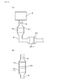
- FIG. 1 is a perspective view of the exhaust gas purification filter according to the first embodiment.
- FIG. 2 is an enlarged cross-sectional view of the exhaust gas purification filter in the axial direction according to the first embodiment.
- FIG. 3 is an enlarged schematic cross-sectional view of the partition wall in the first embodiment.
- FIG. 4 is an enlarged schematic cross-sectional view of the pore wall on which the NOx purification catalyst is supported according to the first embodiment.
- FIG. 5A is a schematic view showing a simplified cross section of the partition wall in the first embodiment
- FIG. 5B is a simplified view of the cross section of the partition wall carrying the NOx purification catalyst in the first embodiment.
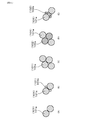
- FIG. 6 is a schematic view showing the arrangement pattern of the raw material particles in the first embodiment.
- FIG. 7A is a schematic diagram showing a simplified cross section of the partition wall on which a small amount of HC purification catalyst is supported in Comparative Form 1
- FIG. 7B is a schematic view showing a large amount of HC purification catalyst in Comparative Form 1.
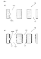
- FIG. 8 (a) is a schematic view showing the outer shape of the exhaust gas purification filter in Experimental Example 1
- FIG. 8 (b) shows the sampling position of the measurement sample in the radial direction of the exhaust gas purification filter in Experimental Example 1. It is the schematic diagram shown (specifically, the sectional view taken along the line VIIIb-VIIIb of FIG. 8C), and FIG.
- FIG. 8C is the measurement in the axial direction and the radial direction of the exhaust gas purification filter in Experimental Example 1. It is a schematic diagram which showed the sampling position of a sample.
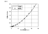
- FIG. 9 is a graph showing an example of the relationship between the gas flow velocity and the pressure loss ⁇ P in Experimental Example 1.
- FIG. 10 is a diagram showing the threshold value of the binarization process in the 3D modeling in Experimental Example 1.
- FIG. 11 is a schematic view showing the configuration of the NOx purification rate measuring device in Experimental Example 1.
- FIG. 12 is a schematic view showing the configuration of the PM collection rate measuring device in Experimental Example 1.
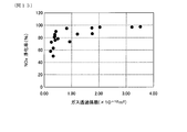
- FIG. 13 is a graph showing the relationship between the gas permeability coefficient and the NOx purification rate in Experimental Example 1.
- FIG. 14 is a graph showing the relationship between the floor area ratio of pores having a pore diameter of 9 ⁇ m or less and the NOx purification rate in Experimental Example 1.
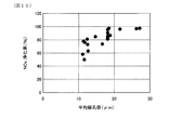
- FIG. 15 is a graph showing the relationship between the average pore size and the NOx purification rate in Experimental Example 1.
- FIG. 16A is a schematic view showing an example of the arrangement configuration of the exhaust gas purification filter in the second embodiment
- FIG. 16B is another example of the arrangement configuration of the exhaust gas purification filter in the second embodiment. It is a schematic diagram which shows.
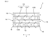
- the exhaust gas purification filter 1 has a honeycomb structure portion 10 and a sealing portion 16.
- the honeycomb structure portion 10 is made of ceramics such as cordierite, and has an outer skin 11, a partition wall 12, and a cell 13.
- the exodermis 11 is, for example, a tubular body.
- the specific shape of the outer skin 11 is, for example, a cylindrical shape having a circular cross-sectional shape in a direction orthogonal to the axial direction Y of the outer skin 11, but a polygonal tubular shape having a polygonal cross-sectional shape such as a quadrangle. May be good.
- the axial direction Y of the tubular outer skin 11 will be described as the axial direction Y of the exhaust gas purification filter 1.
- the axial direction Y of the exhaust gas purification filter is appropriately referred to as the filter axial direction Y.
- the arrow in FIG. 2 indicates the flow of the exhaust gas G when the exhaust gas purification filter 1 is arranged in the path of the exhaust gas G such as an exhaust pipe.
- the partition wall 12 divides the inside of the outer skin 11 into a large number of cells 13.
- the partition wall 12 is also generally referred to as a cell wall.
- the partition walls 12 are provided, for example, in a grid pattern.
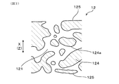
- the exhaust gas purification filter 1 is a porous body, and as shown in FIG. 3, a large number of pores 121 are formed in the partition wall 12. Therefore, the exhaust gas purification filter 1 can accumulate and collect PM contained in the exhaust gas G on the surface of the partition wall 12 or in the pores 121.
- the pores 121 are also commonly referred to as pores.
- PM is a fine particle called a particulate matter, a particulate matter, a particulate, or the like.
- the outer skin 11 and the partition wall 12 are integrally formed.
- the exhaust gas purification filter 1 has a large number of cells 13.
- the cell 13 is surrounded by the partition wall 12 and forms a flow path for the exhaust gas G.
- the extension direction of the cell 13 usually coincides with the filter axial direction Y.
- the cell shape in the filter cross section in the direction orthogonal to the filter axial direction Y is, for example, a quadrangular shape, but the cell shape is not limited to this.
- the cell shape may be a polygon such as a triangle, a quadrangle, a hexagon, or a circle. Further, the cell shape may be a combination of two or more different shapes.
- the exhaust gas purification filter 1 is used by supporting a NOx purification catalyst. That is, the exhaust gas purification filter 1 before supporting the catalyst can be a base material for supporting the NOx purification catalyst.
- the NOx purification catalyst is supported on at least the partition wall 12. It can be said that the exhaust gas purification filter 1 has a supporting surface for supporting the NOx purification catalyst on the partition wall 12.
- the supporting surface is, for example, the flow path surface 125 and the pore wall surface 124a shown in FIGS. 2 to 5.
- the flow path surface 125 is a portion where the partition wall 12 faces the cell 13.
- the pore wall surface 124a is a portion where the pore wall 124 faces the pore 121.
- the NOx purification catalyst is supported on the partition wall 12 as a catalyst layer 17.
- the exhaust gas purification filter 1 is, for example, a columnar body such as a columnar body, and its dimensions can be changed as appropriate.
- the exhaust gas purification filter 1 has an inflow end face 14 and an outflow end face 15 at both ends in the filter axial direction Y.
- the inflow end face 14 is an end face on the side where the exhaust gas G flows in with the exhaust gas purification filter 1 arranged in the flow of the exhaust gas G
- the outflow end face 15 is an end face on the side where the exhaust gas G flows out.
- the inflow end surface 14 and the outflow end surface 15 mean relative surfaces in the filter axial direction Y.
- the inflow end face 14 when one of the end faces is the inflow end face 14, the other is the outflow end face 15.
- the inflow end face 14 can be referred to as a first end face
- the outflow end face 15 can be referred to as a second end face.
- the exhaust gas purification filter 1 has a mesh sealing portion 16.
- the sealing portion 16 closes the inflow end face 14 or the outflow end face 15 of the cell 13 in a staggered manner, for example.
- the mesh sealing portion 16 is made of, for example, ceramics such as cordierite, but may be made of other materials.
- the plug-shaped eye-sealing portion 16 is formed, but the shape of the eye-sealing portion 16 is not particularly limited as long as the inflow end face 14 or the outflow end face 15 can be sealed.
- the cell 13 has, for example, a first cell 131 and a second cell 132.
- the first cell 131 is opened to, for example, the inflow end surface 14 on the inflow side of the exhaust gas G, and the outflow end surface 15 is closed by the sealing portion 16.
- the second cell 132 is opened to, for example, the outflow end surface 15 on the outflow side of the exhaust gas G, and the inflow end surface 14 is closed by the sealing portion 16.
- the first cell 131 and the second cell 132 are adjacent to each other, for example, in the horizontal direction X orthogonal to the filter axial direction Y and in the vertical direction Z orthogonal to both the filter axial direction Y and the horizontal direction X. , Formed alternately side by side. That is, when the inflow end surface 14 or the outflow end surface 15 of the exhaust gas purification filter 1 is viewed from the filter axial direction Y, the first cell 131 and the second cell 132 are arranged in a check pattern, for example.
- the partition wall 12 separates the first cell 131 and the second cell 132 adjacent to each other.
- the pores 121 include communication holes 121c that communicate between the first cell 131 and the second cell 132, and non-communication holes that do not communicate with each other and are not shown.
- the communication hole 121c can be confirmed by observation with an electron microscope such as a scanning electron microscope having a cross section of the partition wall.
- the pores 121 are simplified in two dimensions, but it is considered that most of the pores 121 intersect in three dimensions.
- the pore 121 serves as a path for the exhaust gas G in the partition wall 12.
- the cell 13 also serves as a path for the exhaust gas G like the pores 121, PM is also collected on the flow path surface 125 of the partition wall 12, and NOx is purified on the flow path surface 125 by supporting the NOx purification catalyst on the flow path surface 125.
- the catalyst layer 17 is formed on, for example, the pore wall surface 124a of the partition wall 12.
- the catalyst layer 17 may be formed continuously or discontinuously.
- the catalyst layer 17 is also formed on the flow path surface 125 of the partition wall 12, for example.
- the pressure loss is hereinafter appropriately referred to as "pressure loss”.
- the number and shape of the communication holes can be adjusted by using the porosity, the average pore diameter, and the like as indexes. From the viewpoint of appropriately increasing the number of communication holes and maintaining the strength of the exhaust gas purification filter 1, the porosity is preferably 50 to 70%, more preferably 55 to 65%, and 60 to 65. It is more preferably%. The porosity is measured based on the principle of the mercury intrusion method as shown in the experimental example.
- the catalyst layer 17 contains a NOx purification catalyst.
- a NOx purification catalyst a three-way catalyst made of a precious metal such as Pt, Rh, or Pd can be used.
- the NOx purification catalyst can further purify harmful gas components such as CO and HC in addition to NOx.
- the catalyst layer 17 may further contain alumina, a co-catalyst, and the like. Examples of the co-catalyst include ceria, zirconia, and ceria-zirconia solid solution.
- the method for forming the catalyst layer 17 is not particularly limited, but for example, a method of impregnating the partition wall 12 with a fluid containing a catalyst such as a precious metal and baking the catalyst layer 17 is common.
- the fluid is, for example, a liquid such as a catalytic slurry.
- the NOx purification rate is improved by forming the catalyst layer 17 thinly and widely on the pore wall surface 124a or the like. This is for the following reasons.
- a predetermined amount of the catalyst layer 17 is formed on the exhaust gas purification filter 1
- the catalyst layer 17 is formed thinly so that the catalyst layer 17 is formed in a wide range of the pore wall 124. Therefore, in the exhaust gas purification filter 1, the frequency of contact between the catalyst layer 17 and NOx increases, and NOx is easily purified.
- the pores 121 form a flow path of the fluid such as the catalyst slurry, and by reducing the flow path resistance thereof, the fluid can easily flow and the catalyst layer 17 is formed thin and wide.
- it is effective to increase the pore diameter in the narrow portion 127 of the pore 121, increase the average pore diameter, or increase the pore 121 having a large pore diameter. ..
- the narrow portion 127 is a portion where the pore diameter is smaller than the periphery, and is, for example, a constricted portion of the pore 121 in the partition wall cross section in the wall thickness direction.
- the gas permeability coefficient of the partition wall 12 can be increased.
- the pores 121 having a small pore diameter can be increased.
- the gas permeability coefficient of the partition wall 12 is increased to a predetermined value or more, the average pore diameter is increased to a predetermined value or more, and the pore diameter is increased. It is effective to reduce the small pores 121 to a predetermined value or less.
- the NOx purification rate should be sufficiently increased by setting the gas permeability coefficient to 0.35 ⁇ 10 -12 m 2 or more, the average pore diameter of 12 ⁇ m or more, and the pore volume ratio of 9 ⁇ m or less to 25% or less. Can be done.
- the catalyst layer 17 can be formed thin over a wide range even with the same coating amount, so that the NOx purification rate is improved without increasing the coating amount of the catalyst layer 17. Therefore, the NOx purification rate can be increased while suppressing the increase in pressure loss. Further, by controlling the pores of the exhaust gas purification filter 1 serving as a carrier of the NOx purification catalyst, the NOx purification performance after the catalyst is supported can be improved.
- the catalyst layer 17 is formed thinly and widely on the pore wall surface 124a or the like by the above-mentioned general forming method using the catalyst slurry, and the exhaust gas purification filter 1 after the catalyst is supported exhibits excellent NOx purification performance.
- the methods for measuring and calculating the gas permeability coefficient, average pore diameter, and pore floor area ratio are shown in Experimental Examples.
- the pore volume ratio means the ratio of the volume of pores 121 having a predetermined pore diameter to the total pore volume, and is calculated from the pore diameter distribution measured based on the principle of the mercury intrusion method as shown in the experimental example. Will be done.
- the gas permeability coefficient is preferably 3.0 ⁇ 10 -12 m 2 or less, and preferably 2.5 ⁇ 10 -12 m 2 or less. More preferably, it is 2.0 ⁇ 10 -12 m 2 or less. If the gas permeability coefficient becomes too high, the exhaust gas easily slips through the partition wall 12, and the PM contained in the exhaust gas G also slips through, so that the collection rate is considered to deteriorate.
- the average pore diameter is preferably 25 ⁇ m or less, more preferably 23 ⁇ m or less, and even more preferably 20 ⁇ m or less. Even if the average pore diameter becomes too large, PM slips through easily, and it is considered that the collection rate deteriorates.
- the pore wall area per unit volume of the partition wall 12 is preferably 70,000 ⁇ m 2 / ⁇ m 3 or more.
- the area of the pore wall surface 124a which is the supporting surface on which the catalyst layer is formed, becomes sufficiently large. Therefore, for example, when the same amount of catalyst is supported, the catalyst layer is formed thinner and wider. Therefore, NOx having a slow diffusion rate is efficiently purified in the catalyst layer, and the purification rate is improved.
- the pore wall area per unit volume of the partition wall 12 is more preferably at 85000 ⁇ m 2 / ⁇ m 3 or more, more preferably 90000 ⁇ m 2 / ⁇ m 3 or more.
- the pore wall area per unit volume of the partition wall 12 is 200000 ⁇ m 2 / ⁇ m 3 or less, more preferably 190000 ⁇ m 2 / ⁇ m 3 or less , 180,000 ⁇ m 2 / ⁇ m 3 or less, more preferably.
- the catalyst layer thin and wide as described above in order to improve the NOx purification rate, but from the viewpoint of sufficiently maintaining the NOx diffusion distance (specifically, the reaction time), to some extent. It is considered that this is because it is advantageous to have the thickness of.
- the pore wall area is the area of the pore wall surface 124a, and is the area of the portion where the pore wall 124 forming the pore 121 faces the pore 121.
- the pore wall area can also be, for example, the geometric surface area within the partition wall 12.
- the pore wall area is appropriately referred to as "GSA" below. The measurement method of GSA is shown in an experimental example.
- a catalyst layer 17 is formed on the exhaust gas purification filter 1.
- the supported amount of the catalyst layer 17 is preferably 30 to 150 g / L. In this case, clogging of the pores 121 by the catalyst layer 17 is suppressed while ensuring the required purification performance.
- the average thickness of the catalyst layer 17 is preferably 6 ⁇ m or less.
- NOx purification is performed more efficiently in the catalyst layer 17. This is because, for example, when a predetermined amount of the catalyst layer 17 is formed, the pore wall surface 124a is formed with a small thickness of, for example, 6 ⁇ m or less, as compared with the case where the catalyst layer 17 is formed with a large thickness. This is because the catalyst layer 17 is formed in a wider range of the above.
- it is advantageous that the catalyst layer 17 is formed thin and wide rather than thick and narrow.
- the average thickness of the catalyst layer 17 is 6 ⁇ m or less, NOx purification is sufficiently efficiently performed, so that the NOx purification performance is further improved.
- the average thickness of the catalyst layer 17 is more preferably 5.5 ⁇ m or less. Further, if the thickness of the catalyst layer 17 is too thin, the average thickness of the catalyst layer 17 is preferably 2 ⁇ m or more from the viewpoint that the NOx purification performance may be deteriorated.
- the average thickness of the catalyst layer 7 can be adjusted, for example, by adjusting the amount of the catalyst slurry used when forming the catalyst layer 17.
- the exhaust gas purification filter 1 of this embodiment is manufactured as follows, for example. First, a clay containing a raw material for forming cordierite is prepared.
- the clay is prepared by adjusting silica, talc, aluminum hydroxide, etc. so as to have a cordierite composition, and further adding a binder such as methyl cellulose, a pore-forming material such as graphite, a lubricating oil, water, etc. as appropriate and mixing them. Will be done.
- Alumina and kaolin may be blended so as to have a cordierite composition.
- Porous silica can be used as the silica.
- silica and talc can be the pore forming raw material 101.
- the pore-forming raw material 101 is a material that forms pores 121.
- the pore-forming raw material 101 produces a liquid phase component at the time of firing, whereby pores 121 are formed.
- aluminum hydroxide, alumina, and kaolin can be the aggregate raw material 102.
- the aggregate raw material 102 is a material for forming a ceramic portion other than the pores 121.
- the honeycomb structure portion 10 is a portion composed of an outer skin 11, a partition wall 12, and a cell 13.
- the mesh sealing portion 16 is formed after firing the honeycomb structure portion 10 or before firing. Specifically, for example, using a slurry for forming a sealing portion, the end faces of the honeycomb structure portion 10 after firing or the cell 13 of the molded body having a honeycomb structure before firing are alternately sealed and fired.
- the mesh sealing portion 16 is formed by the above.
- the catalyst layer 17 is formed on the honeycomb structure portion 10 before the formation of the eye seal portion 16 or the honeycomb structure portion 10 after the formation of the eye seal portion 16.
- the catalyst layer 17 is formed by impregnating the partition wall 12 with a catalyst slurry containing a noble metal, alumina, a co-catalyst, etc., and baking the solid component of the slurry onto the partition wall 12. At the time of impregnation, for example, suction can be performed.
- the gas permeability coefficient of the partition wall 12, the average pore diameter, and the pore floor area ratio of 9 ⁇ m or less are adjusted within a predetermined range, so that the flow path resistance of the catalyst slurry becomes small. Therefore, the catalyst layer 17 is formed thin and wide without changing the amount of catalyst. As a result, NOx having a slow diffusion rate is efficiently purified.
- the narrow portion 127 may be increased as follows.
- Pattern A and pattern C are cases where a plurality of pore-forming raw materials 101a having a large particle size are close to each other.
- Pattern B is a case where the pore-forming raw material 101a having a large particle size and the pore-forming raw material 101b having a small particle size are in contact with each other.
- Patterns D and E are cases where the pore-forming raw materials 101 are not in contact with each other and the aggregate raw material 102 is arranged between the pore-forming raw materials 101.
- pattern D an aggregate raw material 102a having a large particle size is arranged between the pore-forming raw materials 101.
- the aggregate raw material 102b having a small particle size is arranged between the pore-forming raw materials 101.
- the size of the narrow portion 127 is as follows. By bringing the pore-forming raw materials 101 into contact with each other as in patterns A to C, the narrow portion 127 can be expanded and a large narrow portion 127 can be formed. On the other hand, when the pore-forming raw material 101 and the aggregate raw material 102 come into contact with each other as in the patterns D and E, the narrow portion 127 becomes smaller. For example, pattern D forms a medium-sized narrow portion 127, and pattern E forms a small-sized narrow portion 127. Therefore, the size of the narrow portion 127 can be adjusted by controlling the contact pattern between the pore-forming raw material 101 and the aggregate raw material 102.
- the pore-forming raw materials 101 are likely to come into contact with each other as in patterns A to C. Therefore, the narrow portion 127 can be enlarged.
- examples of the pore-forming raw material 101 include silica and talc, which may be given a positive charge to silica and a negative charge to talc. Plus and minus may be interchanged. Alternatively, a positive charge may be applied to a part of the mixture of silica and talc, and a negative charge may be applied to the remaining part or all. All the pore-forming raw materials 101 used in the production of the exhaust gas purification filter 1 may be charged, or some pore-forming raw materials 101 may be charged.
- an anionic dispersant and a cationic dispersant can be used to impart the electric charge.
- the pore-forming raw material 101 and the dispersant are mixed in advance. Mixing the pore-forming raw material 101 and the dispersant is called pre-kneading.
- pre-kneading a dispersant is attached to the pore-forming raw material 101 and charged to obtain a positively charged pore-forming raw material 101 and a negatively charged pore-forming raw material 101.
- the pore-forming raw material 101 to which the dispersant is attached, the aggregate raw material 102, and other raw materials are further mixed.
- the pre-kneading time is too long, the communication of the pores 121 may be impaired, so it is preferable to adjust the pre-kneading time appropriately. Further, if the particle size of the aggregate raw material 102 around the pore-forming raw material 101 becomes large, the communication of the pores 121 may be impaired. Therefore, the particle size ratio between the pore-forming raw material 101 and the aggregate raw material 102 It is also preferable to adjust it appropriately.
- the gas permeability coefficient, average pore diameter, and pore volume ratio of pore diameter of 9 ⁇ m or less are the particle size ratio between the pore-forming raw material 101 and the aggregate raw material 102, the type of dispersant, the amount of dispersant added, the pre-kneading time, and the like.
- the above-mentioned desired range can be controlled by adjusting the number of rotations at the time of extrusion, the drying time of clay, and the like.
- FIG. 7 shows a partition wall 92 of the exhaust gas purification filter of this embodiment.
- 7 (a) to 7 (c) simplify the shape of the communication holes (that is, the pores 911, 912, 913) of the partition wall 92, and schematically show the communication holes.
- various pores 911, 912, and 913 having different pore diameters are formed on the partition wall 92 of the exhaust gas purification filter.
- the pores have a constricted pore 911 having a narrow portion 917 having a large pore diameter and a small pore diameter, a pore 912 having a medium pore diameter, and a pore diameter of 912. It will be described by classifying it into three small-sized pores 913.
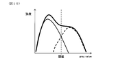
- the catalyst layer in the narrow portion 917 having high flow path resistance is partially thicker than the surroundings. 97 is formed.
- the flow path resistance is high, so that the catalyst slurry does not easily enter the pores 913 and the catalyst layer 97 is difficult to form. Since pores 913 having a small pore diameter are advantageous for collecting PM, the PM collection rate is improved by increasing the number of small pores 913, but the NOx purification performance after the catalyst layer 97 is supported is lowered. To do.
- the catalyst layer 97 in the pores 913 having a small pore diameter by increasing the amount of the catalyst supported.
- the manufacturing cost increases by the amount of the catalyst increase.
- the narrow portion 917 and the medium-sized pores 912 are at least partially blocked by the catalyst layer 97, so that the pressure loss increases.
- Example 1 In this example, as shown in Table 1, a plurality of exhaust gas purification filters 1 having different average pore diameters, gas permeability coefficients, pore floor area ratios with pore diameters of 9 ⁇ m or less, and the like are manufactured. Then, a catalyst layer 17 containing a NOx purification catalyst is formed on the partition wall 12 of the exhaust gas purification filter 1, and the NOx purification rate, PM collection rate, and the like are comparatively evaluated.
- the same codes as those used in the above-mentioned embodiments represent the same components and the like as those in the above-mentioned embodiments, unless otherwise specified.
- the exhaust gas purification filter 1 is a cylinder having a diameter of 118 mm and a length of 120 mm in the filter axial direction Y, and contains cordierite as a main component.
- the exhaust gas purification filter 1 of this example has a thickness of 300 cpsi, and the thickness of the partition wall 12 is 0.216 mm.
- the supported amount of the catalyst layer 17 is 65 g / L.
- silica, talc, and aluminum hydroxide were prepared as raw materials for forming cordierite.
- Silica and talc are the pore-forming raw materials 101
- aluminum hydroxide is the aggregate raw material 102.
- the mixed powder of silica and talc was divided into two parts, one of which was mixed with an anionic dispersant and water, and the other of which was mixed with a cationic dispersant and water. In this way, a slurry-like first mixture containing the-charged pore-forming raw material 101 and a slurry-like second mixture containing the positively-charged pore-forming raw material 101 were obtained. ..
- the amount of the anionic dispersant added in the first mixture is 2 to 15 wt% with respect to the total amount of silica and talc of 100 wt%, and the amount of water added is the amount required to prepare the clay. It is half the amount.
- the anionic dispersant "Nopcos Perth 44-C” manufactured by Sanyo Chemical Industries, Ltd. was used.
- the amount of the cationic dispersant added to the second mixture is 2 to 15 wt% with respect to 100 wt% of the total amount of silica and talc.
- the amount of water added is half the amount required to make clay.
- As the cationic dispersant "Nopcos Perth 092" manufactured by Sanyo Chemical Industries, Ltd. was used.
- the clay was prepared.
- the dispersant polyoxyethylene polyoxypropylene glycerel ether having an average molecular weight of 4550 was used.
- porous silica is used as the silica of the cordierite forming raw material, and this porous silica functions as a pore-forming material.
- graphite may be added as a pore-forming material at the time of preparing the clay.
- the pore-forming material has a function of improving the porosity of the exhaust gas purification filter 1.
- the exhaust gas purification filter 1 was obtained by extruding the clay and firing it at 1410 ° C. to form the sealing portion 16. Further, the catalyst layer 17 was formed on the exhaust gas purification filter 1 by the same method as in the first embodiment. Mixtures of silica and talc (i.e., pore forming material) by changing the D 50 particle size in the range of 5 [mu] m ⁇ 35 [mu] m, is possible to adjust the average pore diameter of the exhaust gas purifying filter 1 in the desired range of, for example, 12 ⁇ m or more it can.
- silica and talc i.e., pore forming material
- the gas permeability coefficient of the exhaust gas purification filter 1 is in a desired range of, for example, 0.35 ⁇ 10 -12 m 2 or more. Can be adjusted to.
- the stirring time of the first mixture and the second mixture and the kneading time of the clay in the range of 5 minutes to 150 minutes, the pore volume ratio of the exhaust gas purification filter having a pore diameter of 9 ⁇ m or less can be reduced to 25% or less, for example. It can be adjusted to the desired range.
- 10 types of exhaust gas purification filters 1 were obtained as shown in Table 1.
- each measured value shown in Table 1 was examined by the method shown below.
- Each measured value is a value for a measurement sample collected from the exhaust gas purification filter 1. The measurement sample was taken from the following sampling position of the exhaust gas purification filter 1.
- FIGS. 8A to 8C The sampling positions are shown in FIGS. 8A to 8C.
- the sampling position is the sealing portion 16 on the inflow end surface 14 side of the central portion 1a in the filter axial direction Y passing through the central portion of the diameter of the exhaust gas purification filter 1.
- a measurement sample is taken from the center of the exhaust gas purification filter 1 in the direction orthogonal to the filter axial direction (specifically, the radial direction). This is because the gas flow velocity is high at the center and NOx blow-through is likely to occur.
- the gas permeability coefficient, the average pore diameter, the pore volume ratio of the pore diameter of 9 ⁇ m or less, etc. are adjusted to the above-mentioned predetermined ranges. This is because the effect of improving the NOx purification rate is sufficiently exhibited.
- Each measured value shown in Table 1 is an arithmetic mean value of the measured values at the above-mentioned three places.
- the state in which the catalyst layer 17 was not formed, specifically, the exhaust gas purification filter 1 before the catalyst layer was formed was measured.
- a measurement sample was taken from the partition wall 12 of the exhaust gas purification filter 1, and the porosity and the average pore diameter of the measurement sample were measured by a mercury porosimeter using the principle of the mercury intrusion method.
- the measurement sample is a substantially cube having a length of 1 cm in the filter axial direction Y, a length of 1 cm in the wall thickness direction, and a length of 1 cm orthogonal to the filter axial direction and the wall thickness direction.
- the average pore size is also called the average pore size.
- As the mercury porosimeter Autopore IV9500 manufactured by Shimadzu Corporation was used.
- the measurement sample was stored in the measurement cell of the mercury porosimeter, and the inside of the measurement cell was depressurized. Then, mercury was introduced into the measurement cell and pressurized, and the pore diameter and the pore volume were measured from the pressure at the time of pressurization and the volume of mercury introduced into the pores of the measurement sample.
- the measurement was performed in the pressure range of 0.5 to 20000 psia.
- 0.5 psia corresponds to 0.35 ⁇ 10 -3 kg / mm 2
- 20000 psia corresponds to 14 kg / mm 2 .
- the range of the pore diameter corresponding to this pressure range is 0.01 to 420 ⁇ m.
- a contact angle of 140 ° and a surface tension of 480 dyn / cm were used as constants when calculating the pore diameter from the pressure.
- the average pore diameter is the pore diameter at an integrated value of 50% of the pore volume.
- the porosity was calculated from the following relational expression.
- the true specific gravity of cordierite is 2.52.
- Porosity (%) total pore volume / (total pore volume + 1 / true specific gravity of cordierite) x 100
- the gas permeability coefficient is obtained from the relationship between the gas flow velocity and the pressure loss.
- the relationship between the gas flow velocity and the pressure loss is measured, for example, by preparing a measurement sample from the exhaust gas purification filter 1 and measuring based on the measurement sample.
- a measurement sample having a diameter of 30 mm, a length of 25 mm in the filter axial direction Y, and a partition wall 12 having a thickness of 200 ⁇ m was used.
- the measurement sample is, for example, an exhaust gas purification filter 1 having an outer size smaller than that of an actual vehicle-mounted product, and is obtained by hollowing out a filter having a desired size from the actual product.
- the measurement sample collection positions are the above-mentioned three locations.
- the hollowed out filter skin can be formed, for example, by cementing.
- polyester tapes are attached to both end faces of the measurement sample in the filter axial direction Y, and the polyester tapes form, for example, a soldering iron so as to form the eye-sealing portions 16 that alternately close the end faces as described above.
- the polyester tape can be partially removed by soldering iron. That is, here, the eye-sealing portion 16 simulated by the polyester tape is formed.
- FIG. 9 shows an example of a relationship diagram between the gas flow velocity (X-axis) and the pressure loss ⁇ P (Y-axis) in the cell 13.
- This relationship diagram shows the measured values (plot points) by the palm poromometer and the calculated values (for example, broken lines) obtained by the following equations (i) to (viii). The equations (i) to (viii) will be described below.
- ⁇ P inlet / exit the opening area A open (unit: m 2 ) of the cell 13
- the opening area A in (unit: m 2 ) of the cell 13 at the inflow end surface 14 of the exhaust gas and the gas flow velocity V channel in the cell 13.
- (Unit: m / s) and air density ⁇ (unit: kg / m 3 ) satisfy the relationship of the following equation (ii).
- ⁇ P channel + ⁇ P wall a gas permeation coefficient k (unit: m 2 ), a length L (unit: m) of the exhaust gas purification filter 1 in the filter axial direction Y, and a hydraulic diameter a 1 (unit: m) of the cell 13. m), the thickness w (unit: m) of the partition wall 12, the friction coefficient F (unit: dimensionless) in the cell 13, the Reynolds number (unit: dimensionless), and the gas viscosity ⁇ (unit: Pa ⁇ s). ) And the gas flow velocity V channel (unit: m / s) in the cell 13 satisfy the relationship of the following equations (iii) to (viii). In equation (iii), e is an exponential function exp.
- the pressure drop value is calculated based on the above formulas (i) to (viii).
- the broken line of the calculated value shown in the relationship diagram between the gas flow velocity (X-axis) and the pressure loss (Y-axis) illustrated in FIG. 9 is the pressure loss value obtained by calculation.
- the pressure drop value is the filter length L, the opening area A open of the cell 13, the hydraulic diameter a 1 , and the thickness w of the partition wall 12, excluding the gas permeability coefficient k. It is calculated by measurement, and these values do not change even if the gas flow velocity is changed. Therefore, by inputting an arbitrary value to the gas permeability coefficient, the calculated value in the relationship diagram between the gas flow velocity (X-axis) and the pressure loss (Y-axis) can be derived.
- the gas permeability coefficient k is a value obtained by back-calculating the gas permeability coefficient from the measured values of the pressure loss measured by the palm polo meter from the equations (i) to (viii).
- the state in which the catalyst layer 17 was not formed, specifically, the exhaust gas purification filter 1 before the catalyst layer was formed was measured.
- a continuous tomographic image of the partition wall 12 of the measurement sample collected from the exhaust gas purification filter 1 was acquired.
- the measurement sample collection positions are the above-mentioned three locations.
- An X-ray CT apparatus "Versa XRM-500" manufactured by Xradia was used for taking continuous tomographic images.
- the imaging conditions are voltage: 80 kV, step: 0.1 °, resolution: 0.684787 ⁇ m / pixel.
- the continuous tomographic image is, for example, in TIF format.
- the continuous tomographic image cross section was read under the condition of 0.6874787 ⁇ m / voxel using the importGeo-Vol function, which is one of the interfaces of the microstructure simulation software “GeoDict” manufactured by Math2Market. Then, in order to separate the bone part (specifically, the ceramic part) and the space part of the read image, the gray value (the intersection when separated into two peaks in the gray value diagram as illustrated in FIG. 10 is used as the threshold value. , The partition wall 12 was modeled in 3D. After that, noise was removed, and unnecessary parts were removed so as to have a desired size (actually, 900 voxel x 600 voxel x partition wall thickness voxel).
- the geometric surface area in the partition wall 12 was Among the Podic functions, which is one of the modules of GrayDic, Estitimate Surface Area is used, and the analysis details are described in J. Ohser and F. Mucklic, Static Analysis Microstraits in Series, Series, and Steel. Introduced from the "Esitimate of real space area", the above-mentioned “F. Mucklic” should be correctly written with the umlaut symbol on the "u”. In the book, it is shown without the umlaut symbol. Table 1 shows the average value of the measured values at the above three locations as GSA.
- the average value of 10 exhaust gas purification filters is adopted for each average pore diameter, and the measurement sample collection positions from each exhaust gas purification filter are three as shown in FIG. The results are shown in Table 1.
- the state in which the catalyst layer 17 was formed, specifically, the exhaust gas purification filter 1 after the catalyst layer was formed was measured.
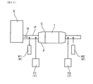
- the exhaust gas purification filter 1 was installed in the exhaust pipe P of the gasoline direct injection engine E having a displacement of 2.0 L, naturally aspirated, and four cylinders.
- a ceramic mat (not shown) was wound around the exhaust gas purification filter 1 and inserted into the filter case C.
- the filter case C was connected to the exhaust pipe P of the engine E via the fitting cone F, and the exhaust gas G from the engine E was passed through the exhaust gas purification filter 1.
- the gas concentration meter 7 includes a first gas concentration meter 71 for measuring the NOx concentration on the entry side before flowing into the exhaust gas purification filter 1, and a NOx concentration on the exit side for measuring the NOx concentration on the exit side from the exhaust gas purification filter 1. No. 2 gas densitometer 72 was used.
- the first gas concentration meter 71 and the second gas concentration meter 72 are both "MEXA-7500" manufactured by HORIBA, Ltd.
- the A / F sensor 8 includes a first A / F sensor 81 for measuring the A / F concentration on the entry side before flowing into the exhaust gas purification filter 1, and an exit side flowing out from the exhaust gas purification filter 1.
- a second A / F sensor 82 was used to measure the A / F concentration of.
- a / F: 14.4 is an A / F value that appears most frequently in WLTC (World-harmonized Light Vehicles Test Cycle) mode driving.
- the conditions of the intake air amount of 50 g / s and the engine speed of 3500 rpm simulate the operating conditions during high-load driving, and the exhaust gas temperature is in a high temperature region of, for example, 750 ° C. or higher.
- the state in which the catalyst layer 17 was formed, specifically, the exhaust gas purification filter 1 after the catalyst layer was formed was measured.
- the exhaust gas purification filter 1 was installed in the exhaust pipe P of the gasoline direct injection engine E having a displacement of 2.0 L, naturally aspirated, and four cylinders, as in the measurement of the NOx purification rate.
- the exhaust gas G from the engine E was passed through the exhaust gas purification filter 1.
- the PM sensor 6 measured the PM concentration on the entry side before flowing into the exhaust gas purification filter 1 and the PM concentration on the exit side flowing out from the exhaust gas purification filter 1.
- the measurement conditions were a temperature of 720 ° C. and an exhaust gas flow rate of 11.0 m 3 / min.
- PM concentration on the entry side is measured by the first PM sensor 61
- PM concentration on the exit side is measured by the second PM sensor 62.
- the collection rate of PM is calculated from the PM concentration on the entry side and the PM concentration on the exit side based on the following formula.
- PM collection rate 100 x (PM concentration on the entry side-PM concentration on the exit side) / PM concentration on the entry side
- the exhaust gas purification filter 1 of the embodiment has a gas permeability coefficient of 0.35 ⁇ 10 -12 m 2 or more and a pore floor area ratio of 9 ⁇ m or less. It is 25% or less and has an average pore diameter of 12 ⁇ m or more. Therefore, the NOx purification rate is high in the examples. From the viewpoint of satisfying the purification rate required for a U / F catalytic converter in a general direct injection engine, the NOx purification rate is preferably 80% or more.
- the U / F catalyst converter is also called an underfloor catalyst, and the U / F catalyst converter will be described in the second embodiment.
- the gas permeability coefficient is 0.35 ⁇ 10 -12 m 2 or more from the viewpoint of improving the NOx purification rate, but from the viewpoint of further improving the NOx purification rate.
- the gas permeability coefficient is preferably 0.40 ⁇ 10 -12 m 2 or more, and more preferably 0.80 ⁇ 10 -12 m 2 or more.
- the average pore diameter is 12 ⁇ m or more from the viewpoint of improving the NOx purification rate, but the average pore diameter is 14 ⁇ m or more from the viewpoint of further improving the NOx purification rate. Is more preferable.
- the pore floor area ratio of the pore diameter of 9 ⁇ m or less is 25% or less, but from the viewpoint of further improving the NOx purification rate. Therefore, the floor area ratio of pores having a pore diameter of 9 ⁇ m or less is more preferably 20% or less, and even more preferably 15% or less. It is considered that this is because when the floor area ratio of pores having a pore diameter of 9 ⁇ m or less is reduced, the number of pores 121 having a pore diameter exceeding 9 ⁇ m increases, and the catalyst layer 17 is formed thin and wide by supporting the catalyst.
- the pore floor area ratio of the pore diameter of 9 ⁇ m or less is preferably 3% or more, and is preferably 10% or more. Is more preferable, and 15% or more is further preferable.
- the pores 121 having a pore diameter of 9 ⁇ m or less greatly contribute to the improvement of the PM collection rate. Therefore, if the number of pores 121 having a pore diameter of 9 ⁇ m or less is too small, the PM collection performance may deteriorate.
- GSA pore wall area per unit volume of the partition wall 12
- the NOx purification rate is further improved.
- GSA is more preferably 85000 ⁇ m 2 / ⁇ m 3 or more, further preferably 90000 ⁇ m 2 / ⁇ m 3 or more.
- any one of the conditions of a gas transmittance of 0.35 ⁇ 10 -12 m 2 or more, a pore floor area ratio of 25% or less with a pore diameter of 9 ⁇ m or less, and an average pore diameter of 12 ⁇ m or more was satisfied. Not. Therefore, in the comparative example, the NOx purification rate is low.
- the S / C catalyst 1A is, for example, a honeycomb structure formed of cordierite. Although the configuration of the S / C catalyst 1A is not shown, the S / C catalyst 1A has the same shape as the honeycomb structure portion 10 in the first embodiment. Specifically, the S / C catalyst 1A has an outer skin 11, a partition wall 12, and a cell 13, and does not have a sealing portion.
- the honeycomb structure used for the S / C catalyst 1A is also called a monolith carrier, and a three-way catalyst is supported on the partition wall 12. It is also possible to use the exhaust gas purification filter 1 having the honeycomb structure portion 10 and the sealing portion 16 as the S / C catalyst.
- the U / F catalyst converter 1B (that is, the under floor catalyst) is located at the U / F position (that is, the under floor position) that is under the floor of the vehicle downstream of the S / C catalyst 1A. Converter) is placed.
- the U / F catalytic converter 1B for example, the exhaust gas purification filter 1 of the first embodiment can be used.
- the U / F catalytic converter 1B is also generally referred to as a second converter.
- the S / C catalyst 1A and the U / F catalyst converter 1B are inserted into different cases C1 and C2, and the cases C1 and C2 are connected to the exhaust pipe P. In the path of the exhaust pipe P, the S / C catalyst 1A and the U / F catalyst converter 1B are arranged at a predetermined distance.
- the exhaust gas purification filter 1 may be used to form a tandem type catalyst unit. Specifically, as shown in FIG. 15B, the S / C catalyst 1A and the rear catalyst 1C are inserted into the same case C3, and this case C3 is connected to the exhaust pipe P. As the rear catalyst 1C, for example, the exhaust gas purification filter 1 of the first embodiment can be used.
- the exhaust gas purification filter 1 is used as a U / F catalyst converter 1B, a rear catalyst 1C of a tandem type catalyst unit, etc., and is used on the downstream side of an S / C catalyst 1A on which a three-way catalyst is supported.
- an S / C catalyst 1A arranged on the upstream side, harmful gas components such as CO, HC, and NOx are purified by the three-way catalyst.
- harmful gas components such as CO, HC, and NOx are purified by the three-way catalyst.
- CO and HC are sufficiently purified.
- the exhaust gas purification filter 1 is used for purifying the exhaust gas G of an internal combustion engine such as a diesel engine or a gasoline engine, and is suitable for applications discharged from a gasoline engine. That is, the exhaust gas purification filter 1 is preferably a gasoline particulate filter.
- the gasoline particulate filter is called a GPF. In GPF, not only the purification performance of PM but also the purification catalyst for harmful gas components such as NOx is coated, and the purification of harmful gas components is also required.
Abstract
Provided is an exhaust gas purification filter (1) that is used with a NOx purification catalyst supported therein. The exhaust gas purification filter (1) comprises honeycomb structure portions (10) and sealed portions (16). The honeycomb structure portions (10) have partitions (12) and cells (13). Multiple pores are formed in the partitions (12). The cells (13) are divided by the partitions (12) and form an exhaust gas channel. The sealed portion (16) blocks an exhaust gas inflow end face (14) or outflow end face (15) of a cell (13). The partition (12) has a gas permeability coefficient of 0.35×10⁻¹² or greater, a pore volume percent for pore sizes of 9 μm or less of 25% or less, and an average pore size of 12 μm or greater.
Description
本出願は、2019年4月26日に出願された日本出願番号2019-086489号に基づくもので、ここにその記載内容を援用する。
This application is based on Japanese Application No. 2019-086489 filed on April 26, 2019, and the contents of the description are incorporated herein by reference.
本開示は、NOx浄化触媒を担持して用いられる排ガス浄化フィルタに関する。
The present disclosure relates to an exhaust gas purification filter used by supporting a NOx purification catalyst.
ディーゼルエンジン、ガソリンエンジン等の内燃機関、ボイラー等の熱機関から排出される排ガス中には、パティキュレートと呼ばれる粒子状物質が含まれる。パティキュレートのことを以下適宜「PM」という。排ガス中のPMを捕集するために排ガス浄化フィルタが用いられている。
Exhaust gas emitted from internal combustion engines such as diesel engines and gasoline engines, and heat engines such as boilers contains particulate matter called particulate matter. Particulate is hereinafter appropriately referred to as "PM". An exhaust gas purification filter is used to collect PM in the exhaust gas.
排ガス浄化フィルタは、一般に、多孔質の隔壁によって区画されて形成された複数のセルを有すると共に、セルの両端のうち一方を封止する目封止部とを有する。排ガス浄化フィルタには、圧力損失を低減しつつ、排ガス中に含まれるPMを隔壁の細孔内に捕集することが求められている。なお、圧力損失のことを以下適宜「圧損」という。
The exhaust gas purification filter generally has a plurality of cells formed by being partitioned by a porous partition wall, and also has a mesh sealing portion for sealing one of both ends of the cell. The exhaust gas purification filter is required to collect PM contained in the exhaust gas into the pores of the partition wall while reducing the pressure loss. The pressure loss is hereinafter appropriately referred to as "pressure loss".
例えば、特許文献1には、気孔率が45~70%であり、所定の平均細孔径差率が35%以下であり、平均細孔径が15~30μmであり、かつ、バブルポイント法で測定される最大細孔径が150μm以下であるフィルタが開示されている。特許文献1によれば、上記構成を採用することにより、PM堆積時における圧損を低減できるとしている。
For example, in Patent Document 1, the porosity is 45 to 70%, the predetermined average pore diameter difference ratio is 35% or less, the average pore diameter is 15 to 30 μm, and the measurement is performed by the bubble point method. A filter having a maximum pore diameter of 150 μm or less is disclosed. According to Patent Document 1, by adopting the above configuration, the pressure loss at the time of PM deposition can be reduced.
近年、排ガス浄化フィルタに、NOx等の有害物質に対する浄化性能を付与する要求があり、例えばNOx浄化触媒が排ガス浄化フィルタに担持される。NOxは、触媒層での拡散速度が遅いため、触媒層が厚く形成されるよりも、同じ量の触媒層が薄く広く形成される方が効率的に浄化される。しかし、特許文献1に記載のような従来の排ガス浄化フィルタでは、触媒が担持される気孔に狭小部分が形成され、触媒スラリーの流路抵抗が高くなり、触媒の担持により触媒層が部分的に厚く形成されやすい。したがって、従来の排ガス浄化フィルタには、触媒層でのNOxの浄化性能に更なる改良の余地がある。
In recent years, there has been a demand for exhaust gas purification filters to be provided with purification performance for harmful substances such as NOx. For example, NOx purification catalysts are supported on exhaust gas purification filters. Since the diffusion rate of NOx in the catalyst layer is slow, it is more efficiently purified when the same amount of catalyst layer is formed thin and wide than when the catalyst layer is formed thick. However, in the conventional exhaust gas purification filter as described in Patent Document 1, narrow portions are formed in the pores on which the catalyst is supported, the flow path resistance of the catalyst slurry increases, and the catalyst layer is partially supported by the catalyst. It is easy to be formed thick. Therefore, there is room for further improvement in the NOx purification performance in the catalyst layer of the conventional exhaust gas purification filter.
本開示は、触媒の担持により優れたNOxの浄化性能を示すことができる排ガス浄化フィルタを提供しようとするものである。
The present disclosure is intended to provide an exhaust gas purification filter capable of exhibiting excellent NOx purification performance by supporting a catalyst.
本開示の一態様は、NOx浄化触媒を担持して用いられる排ガス浄化フィルタであって、
多数の細孔が形成された隔壁と、該隔壁によって区画され、排ガスの流路を形成する複数のセルとを有するハニカム構造部と、
上記セルにおける上記排ガスの流入端面又は流出端面を互い違いに閉塞する目封止部と、を備え、
上記隔壁は、ガス透過係数が0.35×10⁻¹²m2以上であり、細孔径9μm以下の細孔容積率が25%以下であり、平均細孔径が12μm以上である、排ガス浄化フィルタにある。 One aspect of the present disclosure is an exhaust gas purification filter used by supporting a NOx purification catalyst.
A honeycomb structure having a partition wall in which a large number of pores are formed, and a plurality of cells partitioned by the partition wall and forming an exhaust gas flow path.
A mesh sealing portion for alternately closing the inflow end face or the outflow end face of the exhaust gas in the cell is provided.
The partition wall is used as an exhaust gas purification filter having a gas permeability coefficient of 0.35 × 10 -12 m 2 or more, a pore floor area ratio of 9 μm or less of 25% or less, and an average pore diameter of 12 μm or more. is there.
上記排ガス浄化フィルタは、隔壁のガス透過係数、隔壁における細孔径9μm以下の細孔容積率、及び隔壁の平均細孔径が上記のように調整されている。このような隔壁では、細孔の流路抵抗が小いため、NOx浄化触媒の担持により触媒層が薄く広く形成される。その結果、拡散速度の遅いNOxが効率的に浄化される。したがって、排ガス浄化フィルタは、NOx浄化触媒の担持により、高いNOx浄化率を示す。
In the exhaust gas purification filter, the gas permeability coefficient of the partition wall, the floor area ratio of pores having a pore diameter of 9 μm or less in the partition wall, and the average pore diameter of the partition wall are adjusted as described above. In such a partition wall, since the flow path resistance of the pores is small, the catalyst layer is formed thin and wide by supporting the NOx purification catalyst. As a result, NOx having a slow diffusion rate is efficiently purified. Therefore, the exhaust gas purification filter exhibits a high NOx purification rate due to the support of the NOx purification catalyst.
以上のごとく、上記態様によれば、触媒の担持により優れたNOxの浄化性能を示すことができる排ガス浄化フィルタを提供することができる。
なお、請求の範囲に記載した括弧内の符号は、後述する実施形態に記載の具体的手段との対応関係を示すものであり、本開示の技術的範囲を限定するものではない。 As described above, according to the above aspect, it is possible to provide an exhaust gas purification filter capable of exhibiting excellent NOx purification performance by supporting a catalyst.
The reference numerals in parentheses described in the claims indicate the correspondence with the specific means described in the embodiments described later, and do not limit the technical scope of the present disclosure.
(実施形態1)
排ガス浄化フィルタ1に係る実施形態について、図1~図6を参照して説明する。図1に示されるように、排ガス浄化フィルタ1は、ハニカム構造部10と目封止部16とを有する。ハニカム構造部10は、例えば、コージェライトなどのセラミックスから構成され、外皮11、隔壁12、セル13を有する。 (Embodiment 1)
An embodiment according to the exhaustgas purification filter 1 will be described with reference to FIGS. 1 to 6. As shown in FIG. 1, the exhaust gas purification filter 1 has a honeycomb structure portion 10 and a sealing portion 16. The honeycomb structure portion 10 is made of ceramics such as cordierite, and has an outer skin 11, a partition wall 12, and a cell 13.
排ガス浄化フィルタ1に係る実施形態について、図1~図6を参照して説明する。図1に示されるように、排ガス浄化フィルタ1は、ハニカム構造部10と目封止部16とを有する。ハニカム構造部10は、例えば、コージェライトなどのセラミックスから構成され、外皮11、隔壁12、セル13を有する。 (Embodiment 1)
An embodiment according to the exhaust
図1及び図2に示されるように、外皮11は例えば筒状体である。外皮11の具体的な形状は、例えば、外皮11の軸方向Yと直交方向での断面形状が円形となる円筒状であるが、断面形状が四角形などの多角形となる多角筒状であってもよい。本実施形態では、この筒状の外皮11の軸方向Yを排ガス浄化フィルタ1の軸方向Yとして説明する。排ガス浄化フィルタの軸方向Yのことを適宜、フィルタ軸方向Yという。また、図2における矢印は、排ガス浄化フィルタ1を排気管などの排ガスGの通り道に配置した際の排ガスGの流れを示す。
As shown in FIGS. 1 and 2, the exodermis 11 is, for example, a tubular body. The specific shape of the outer skin 11 is, for example, a cylindrical shape having a circular cross-sectional shape in a direction orthogonal to the axial direction Y of the outer skin 11, but a polygonal tubular shape having a polygonal cross-sectional shape such as a quadrangle. May be good. In the present embodiment, the axial direction Y of the tubular outer skin 11 will be described as the axial direction Y of the exhaust gas purification filter 1. The axial direction Y of the exhaust gas purification filter is appropriately referred to as the filter axial direction Y. Further, the arrow in FIG. 2 indicates the flow of the exhaust gas G when the exhaust gas purification filter 1 is arranged in the path of the exhaust gas G such as an exhaust pipe.
隔壁12は、外皮11の内側を多数のセル13に区画する。隔壁12は、一般に、セル壁とも呼ばれる。隔壁12は、例えば格子状に設けられる。排ガス浄化フィルタ1は多孔体であり、図3に示されるように、隔壁12には多数の細孔121が形成されている。したがって、排ガス浄化フィルタ1は、隔壁12の表面や細孔121内に排ガスG中に含まれるPMを堆積させて捕集することができる。細孔121は、一般に、気孔とも呼ばれる。PMは、粒子状物質、パティキュレートマター、パティキュレートなどと呼ばれる微小粒子である。外皮11と隔壁12とは一体的に形成されている。
The partition wall 12 divides the inside of the outer skin 11 into a large number of cells 13. The partition wall 12 is also generally referred to as a cell wall. The partition walls 12 are provided, for example, in a grid pattern. The exhaust gas purification filter 1 is a porous body, and as shown in FIG. 3, a large number of pores 121 are formed in the partition wall 12. Therefore, the exhaust gas purification filter 1 can accumulate and collect PM contained in the exhaust gas G on the surface of the partition wall 12 or in the pores 121. The pores 121 are also commonly referred to as pores. PM is a fine particle called a particulate matter, a particulate matter, a particulate, or the like. The outer skin 11 and the partition wall 12 are integrally formed.
図1及び図2に示されるように、排ガス浄化フィルタ1は、多数のセル13を有する。セル13は、隔壁12に囲まれて排ガスGの流路を形成する。セル13の伸長方向は、通常、フィルタ軸方向Yと一致する。
As shown in FIGS. 1 and 2, the exhaust gas purification filter 1 has a large number of cells 13. The cell 13 is surrounded by the partition wall 12 and forms a flow path for the exhaust gas G. The extension direction of the cell 13 usually coincides with the filter axial direction Y.
フィルタ軸方向Yと直交方向のフィルタ断面におけるセル形状は、例えば、四角形状であるが、これに限定されない。セル形状は、三角形状、四角形状、六角形状などの多角形や円形状などであってもよい。また、セル形状は、2種以上の異なる形状の組み合わせであってもよい。
The cell shape in the filter cross section in the direction orthogonal to the filter axial direction Y is, for example, a quadrangular shape, but the cell shape is not limited to this. The cell shape may be a polygon such as a triangle, a quadrangle, a hexagon, or a circle. Further, the cell shape may be a combination of two or more different shapes.
排ガス浄化フィルタ1は、NOx浄化触媒を担持して用いられる。つまり、触媒担持前の排ガス浄化フィルタ1は、NOx浄化触媒を担持するための基材となりうる。NOx浄化触媒は、少なくとも隔壁12に担持される。排ガス浄化フィルタ1は、隔壁12に、NOx浄化触媒を担持するための担持面を有するということができる。担持面は、例えば、図2~図5に示される流路面125、細孔壁面124aである。流路面125は、隔壁12がセル13に面する部分である。細孔壁面124aは、細孔壁124が細孔121に面する部分である。NOx浄化触媒は、触媒層17として隔壁12に担持される。
The exhaust gas purification filter 1 is used by supporting a NOx purification catalyst. That is, the exhaust gas purification filter 1 before supporting the catalyst can be a base material for supporting the NOx purification catalyst. The NOx purification catalyst is supported on at least the partition wall 12. It can be said that the exhaust gas purification filter 1 has a supporting surface for supporting the NOx purification catalyst on the partition wall 12. The supporting surface is, for example, the flow path surface 125 and the pore wall surface 124a shown in FIGS. 2 to 5. The flow path surface 125 is a portion where the partition wall 12 faces the cell 13. The pore wall surface 124a is a portion where the pore wall 124 faces the pore 121. The NOx purification catalyst is supported on the partition wall 12 as a catalyst layer 17.
排ガス浄化フィルタ1は、例えば、円柱状等の柱状体であり、その寸法は適宜変更可能である。排ガス浄化フィルタ1は、フィルタ軸方向Yの両端に流入端面14、流出端面15を有する。流入端面14は、排ガス浄化フィルタ1が排ガスGの流れに配置された状態で排ガスGが流入する側の端面であり、流出端面15は、排ガスGが流出する側の端面である。排ガス浄化フィルタ1が排ガスGの流れに配置されていない状態では、流入端面14及び流出端面15は、フィルタ軸方向Yでの相対的な面を意味する。つまり、いずれか一方の端面が流入端面14である場合に、他方が流出端面15となる。例えば、流入端面14のことを第1端面、流出端面15のことを第2端面ということもできる。
The exhaust gas purification filter 1 is, for example, a columnar body such as a columnar body, and its dimensions can be changed as appropriate. The exhaust gas purification filter 1 has an inflow end face 14 and an outflow end face 15 at both ends in the filter axial direction Y. The inflow end face 14 is an end face on the side where the exhaust gas G flows in with the exhaust gas purification filter 1 arranged in the flow of the exhaust gas G, and the outflow end face 15 is an end face on the side where the exhaust gas G flows out. In a state where the exhaust gas purification filter 1 is not arranged in the flow of the exhaust gas G, the inflow end surface 14 and the outflow end surface 15 mean relative surfaces in the filter axial direction Y. That is, when one of the end faces is the inflow end face 14, the other is the outflow end face 15. For example, the inflow end face 14 can be referred to as a first end face, and the outflow end face 15 can be referred to as a second end face.
排ガス浄化フィルタ1は、目封止部16を有する。目封止部16は、セル13の流入端面14又は流出端面15を例えば互い違いに閉塞する。目封止部16は、例えば、コージェライト等のセラミックスにより構成されるが、その他の材質であってもよい。図2では、プラグ状の目封止部16が形成されているが、目封止部16の形状は、流入端面14又は流出端面15を封止できれば特に限定されない。なお、構成の図示を省略するが、例えば流入端面14又は流出端面15において隔壁12の一部を変形させることにより、目封止部16を形成することも可能である。この場合には、隔壁12の一部によって目封止部16が形成されるため、隔壁12と目封止部16とが一体的、連続的に形成される。
The exhaust gas purification filter 1 has a mesh sealing portion 16. The sealing portion 16 closes the inflow end face 14 or the outflow end face 15 of the cell 13 in a staggered manner, for example. The mesh sealing portion 16 is made of, for example, ceramics such as cordierite, but may be made of other materials. In FIG. 2, the plug-shaped eye-sealing portion 16 is formed, but the shape of the eye-sealing portion 16 is not particularly limited as long as the inflow end face 14 or the outflow end face 15 can be sealed. Although the configuration is not shown, it is also possible to form the sealing portion 16 by deforming a part of the partition wall 12 on the inflow end face 14 or the outflow end face 15, for example. In this case, since the sealing portion 16 is formed by a part of the partition wall 12, the partition wall 12 and the sealing portion 16 are integrally and continuously formed.
セル13としては、例えば第1セル131と第2セル132とを有する。図2に示されるように、第1セル131は、例えば排ガスGの流入側となる流入端面14に開口し、流出端面15では目封止部16により閉塞されている。第2セル132は、例えば排ガスGの流出側となる流出端面15に開口し、流入端面14では目封止部16により閉塞されている。
The cell 13 has, for example, a first cell 131 and a second cell 132. As shown in FIG. 2, the first cell 131 is opened to, for example, the inflow end surface 14 on the inflow side of the exhaust gas G, and the outflow end surface 15 is closed by the sealing portion 16. The second cell 132 is opened to, for example, the outflow end surface 15 on the outflow side of the exhaust gas G, and the inflow end surface 14 is closed by the sealing portion 16.
第1セル131と第2セル132とは、フィルタ軸方向Yに直交する横方向Xにおいても、フィルタ軸方向Yおよび横方向Xの双方に直交する縦方向Zにおいても、例えば、互いに隣り合うよう、交互に並んで形成される。つまり、フィルタ軸方向Yから排ガス浄化フィルタ1の流入端面14または流出端面15を見たとき、第1セル131と第2セル132とが、例えば、チェック模様状に配される。
The first cell 131 and the second cell 132 are adjacent to each other, for example, in the horizontal direction X orthogonal to the filter axial direction Y and in the vertical direction Z orthogonal to both the filter axial direction Y and the horizontal direction X. , Formed alternately side by side. That is, when the inflow end surface 14 or the outflow end surface 15 of the exhaust gas purification filter 1 is viewed from the filter axial direction Y, the first cell 131 and the second cell 132 are arranged in a check pattern, for example.
隔壁12は、図2に示されるように、互いに隣り合う第1セル131、第2セル132を隔てている。隔壁12内では、図3に示されるように、細孔壁124により多数の細孔121が形成されている。細孔121には、第1セル131と第2セル132との間を連通させる連通孔121cと、連通させない、図示を省略する非連通孔とが含まれる。連通孔121cは、例えば、隔壁断面の走査型電子顕微鏡などの電子顕微鏡観察にて確認できる。図3においては細孔121を二次元に簡略化して示してあるが、細孔121は三次元に交差するものが大半を占めると考えられる。細孔121は、隔壁12内での排ガスGの経路となる。排ガスGが細孔121内を通過することにより、排ガスG中のPMが細孔壁面124aに捕集される。また、細孔壁124にNOx浄化触媒を担持させることにより、細孔121内を通過する排ガスG中に含まれるNOx等の有害ガス成分が、NOx浄化触媒により浄化される。セル13も、細孔121と同様に排ガスGの経路となり、PMは隔壁12の流路面125でも捕集され、流路面125にNOx浄化触媒を担持することにより、NOxが流路面125でも浄化される。
As shown in FIG. 2, the partition wall 12 separates the first cell 131 and the second cell 132 adjacent to each other. In the partition wall 12, as shown in FIG. 3, a large number of pores 121 are formed by the pore walls 124. The pores 121 include communication holes 121c that communicate between the first cell 131 and the second cell 132, and non-communication holes that do not communicate with each other and are not shown. The communication hole 121c can be confirmed by observation with an electron microscope such as a scanning electron microscope having a cross section of the partition wall. In FIG. 3, the pores 121 are simplified in two dimensions, but it is considered that most of the pores 121 intersect in three dimensions. The pore 121 serves as a path for the exhaust gas G in the partition wall 12. As the exhaust gas G passes through the pores 121, PM in the exhaust gas G is collected on the pore wall surface 124a. Further, by supporting the NOx purification catalyst on the pore wall 124, harmful gas components such as NOx contained in the exhaust gas G passing through the pores 121 are purified by the NOx purification catalyst. The cell 13 also serves as a path for the exhaust gas G like the pores 121, PM is also collected on the flow path surface 125 of the partition wall 12, and NOx is purified on the flow path surface 125 by supporting the NOx purification catalyst on the flow path surface 125. To.
図4に示されるように、触媒層17は、例えば隔壁12の細孔壁面124aに形成される。触媒層17は連続的に形成されても、不連続的に形成されてもよい。触媒層17は、例えば、隔壁12の流路面125にも形成される。
As shown in FIG. 4, the catalyst layer 17 is formed on, for example, the pore wall surface 124a of the partition wall 12. The catalyst layer 17 may be formed continuously or discontinuously. The catalyst layer 17 is also formed on the flow path surface 125 of the partition wall 12, for example.
連通孔を適度に増やすことにより、圧力損失の低減とPM捕集率の向上との両立化がはかれる。圧力損失のことを、以下適宜「圧損」という。連通孔の数、形状などは、気孔率、平均細孔径などを指標として調整することができる。連通孔を適度に増やすという観点、排ガス浄化フィルタ1の強度を維持するという観点から、気孔率は、50~70%であることが好ましく、55~65%であることがより好ましく、60~65%であることがさらに好ましい。気孔率は、実験例にて示すように水銀圧入法の原理に基づいて測定される。
By appropriately increasing the number of communication holes, it is possible to achieve both reduction of pressure loss and improvement of PM collection rate. The pressure loss is hereinafter appropriately referred to as "pressure loss". The number and shape of the communication holes can be adjusted by using the porosity, the average pore diameter, and the like as indexes. From the viewpoint of appropriately increasing the number of communication holes and maintaining the strength of the exhaust gas purification filter 1, the porosity is preferably 50 to 70%, more preferably 55 to 65%, and 60 to 65. It is more preferably%. The porosity is measured based on the principle of the mercury intrusion method as shown in the experimental example.
触媒層17は、NOx浄化触媒を含む。NOx浄化触媒としては、Pt、Rh、Pdなどの貴金属からなる三元触媒を用いることができる。この場合には、NOx浄化触媒が、NOxの他に、さらにCO、HCなどの有害ガス成分を浄化できる。触媒層17は、さらにアルミナ、助触媒などを含有していてもよい。助触媒としては、セリア、ジルコニア、セリア-ジルコニア固溶体などが例示される。
The catalyst layer 17 contains a NOx purification catalyst. As the NOx purification catalyst, a three-way catalyst made of a precious metal such as Pt, Rh, or Pd can be used. In this case, the NOx purification catalyst can further purify harmful gas components such as CO and HC in addition to NOx. The catalyst layer 17 may further contain alumina, a co-catalyst, and the like. Examples of the co-catalyst include ceria, zirconia, and ceria-zirconia solid solution.
触媒層17の形成方法は、特に限定されるものではないが、例えば、貴金属などの触媒を含む流体を隔壁12に含浸させ、焼き付ける方法が一般的である。流体は例えば触媒スラリーなどの液体である。
The method for forming the catalyst layer 17 is not particularly limited, but for example, a method of impregnating the partition wall 12 with a fluid containing a catalyst such as a precious metal and baking the catalyst layer 17 is common. The fluid is, for example, a liquid such as a catalytic slurry.
NOxは触媒層での拡散速度が遅いため、触媒層が厚いと触媒層でのNOxの拡散が不十分となる。触媒層17が細孔壁面124a等に薄く広く形成されることにより、NOx浄化率が向上する。これは、次のような理由からである。排ガス浄化フィルタ1に例えば所定量の触媒層17を形成する場合、触媒層17が薄く形成されることにより、触媒層17が細孔壁124の広い範囲に形成されることとなる。そのため、排ガス浄化フィルタ1では、触媒層17とNOxとの接触頻度が増加し、NOxが浄化されやすい。また、NOxは、触媒層17での拡散速度が遅いため、触媒層17の厚みが小さくても十分に浄化される。触媒層形成時には、細孔121が触媒スラリーなどの流体の流路を形成し、その流路抵抗を小さくすることにより、流体が流れ易くなり、触媒層17が薄く広く形成される。流路抵抗を小さくするためには、例えば、細孔121の狭小部127での細孔径を大きくしたり、平均細孔径を大きくしたり、細孔径の大きな細孔121を増やすことが有効である。狭小部127は、細孔径が周囲よりも小さくなる部分であり、例えば、壁厚方向での隔壁断面における細孔121のくびれ部分である。狭小部127を大きくすることにより、隔壁12のガス透過係数を大きくすることができる。また、細孔径の小さな細孔121を減らすことにより、細孔径の大きな細孔121を増やすことができる。
Since NOx has a slow diffusion rate in the catalyst layer, if the catalyst layer is thick, the diffusion of NOx in the catalyst layer will be insufficient. The NOx purification rate is improved by forming the catalyst layer 17 thinly and widely on the pore wall surface 124a or the like. This is for the following reasons. When, for example, a predetermined amount of the catalyst layer 17 is formed on the exhaust gas purification filter 1, the catalyst layer 17 is formed thinly so that the catalyst layer 17 is formed in a wide range of the pore wall 124. Therefore, in the exhaust gas purification filter 1, the frequency of contact between the catalyst layer 17 and NOx increases, and NOx is easily purified. Further, since NOx has a slow diffusion rate in the catalyst layer 17, even if the thickness of the catalyst layer 17 is small, NOx is sufficiently purified. At the time of forming the catalyst layer, the pores 121 form a flow path of the fluid such as the catalyst slurry, and by reducing the flow path resistance thereof, the fluid can easily flow and the catalyst layer 17 is formed thin and wide. In order to reduce the flow path resistance, for example, it is effective to increase the pore diameter in the narrow portion 127 of the pore 121, increase the average pore diameter, or increase the pore 121 having a large pore diameter. .. The narrow portion 127 is a portion where the pore diameter is smaller than the periphery, and is, for example, a constricted portion of the pore 121 in the partition wall cross section in the wall thickness direction. By increasing the narrow portion 127, the gas permeability coefficient of the partition wall 12 can be increased. Further, by reducing the pores 121 having a small pore diameter, the pores 121 having a large pore diameter can be increased.
触媒層17を薄く広く形成させてNOx浄化率を十分向上させるためには、隔壁12のガス透過係数を所定値以上にまで高くし、平均細孔径を所定値以上にまで大きくし、細孔径の小さな細孔121を所定値以下にまで減らすことが有効である。具体的には、ガス透過係数0.35×10⁻¹²m2以上、平均細孔径12μm以上、細孔径9μm以下の細孔容積率25%以下とすることにより、NOx浄化率を十分高くすることができる。また、流路抵抗を小さくすることで、同一のコート量であっても、触媒層17を広範囲に薄く形成することができるため、触媒層17のコート量を増やすことなくNOx浄化率を向上させることができるため、圧損上昇を抑制しつつ、NOx浄化率を高くすることができる。また、NOx浄化触媒の担体となる排ガス浄化フィルタ1の細孔制御により、触媒担持後のNOx浄化性能を向上させることができる。例えば、触媒スラリーを用いた上述の一般的な形成方法により、触媒層17が細孔壁面124aなどに薄く広く形成され、触媒担持後の排ガス浄化フィルタ1は、優れたNOx浄化性能を示す。ガス透過係数、平均細孔径、細孔容積率の測定、算出方法は、実験例にて示す。細孔容積率は、全細孔容積に対する所定細孔径の細孔121の容積が占める割合を意味し、実験例にて示すように水銀圧入法の原理に基づいて測定される細孔径分布から算出される。
In order to form the catalyst layer 17 thin and wide and sufficiently improve the NOx purification rate, the gas permeability coefficient of the partition wall 12 is increased to a predetermined value or more, the average pore diameter is increased to a predetermined value or more, and the pore diameter is increased. It is effective to reduce the small pores 121 to a predetermined value or less. Specifically, the NOx purification rate should be sufficiently increased by setting the gas permeability coefficient to 0.35 × 10 -12 m 2 or more, the average pore diameter of 12 μm or more, and the pore volume ratio of 9 μm or less to 25% or less. Can be done. Further, by reducing the flow path resistance, the catalyst layer 17 can be formed thin over a wide range even with the same coating amount, so that the NOx purification rate is improved without increasing the coating amount of the catalyst layer 17. Therefore, the NOx purification rate can be increased while suppressing the increase in pressure loss. Further, by controlling the pores of the exhaust gas purification filter 1 serving as a carrier of the NOx purification catalyst, the NOx purification performance after the catalyst is supported can be improved. For example, the catalyst layer 17 is formed thinly and widely on the pore wall surface 124a or the like by the above-mentioned general forming method using the catalyst slurry, and the exhaust gas purification filter 1 after the catalyst is supported exhibits excellent NOx purification performance. The methods for measuring and calculating the gas permeability coefficient, average pore diameter, and pore floor area ratio are shown in Experimental Examples. The pore volume ratio means the ratio of the volume of pores 121 having a predetermined pore diameter to the total pore volume, and is calculated from the pore diameter distribution measured based on the principle of the mercury intrusion method as shown in the experimental example. Will be done.
PMの捕集率の悪化を抑制するという観点からは、ガス透過係数は、3.0×10⁻¹²m2以下であることが好ましく、2.5×10⁻¹²m2以下であることがより好ましく、2.0×10⁻¹²m2以下であることがさらに好ましい。ガス透過係数が高くなりすぎると、隔壁12内で排ガスがすり抜けやすく、排ガスG中に含まれるPMのすり抜けも多くなるために捕集率が悪化すると考えられる。同様の観点から、平均細孔径は25μm以下であることが好ましく、23μm以下であることがより好ましく、20μm以下であることがさらに好ましい。平均細孔径が大きくなりすぎても、PMのすり抜けが起こり易くなるため、捕集率が悪化すると考えられる。
From the viewpoint of suppressing deterioration of the PM collection rate, the gas permeability coefficient is preferably 3.0 × 10 -12 m 2 or less, and preferably 2.5 × 10 -12 m 2 or less. More preferably, it is 2.0 × 10 -12 m 2 or less. If the gas permeability coefficient becomes too high, the exhaust gas easily slips through the partition wall 12, and the PM contained in the exhaust gas G also slips through, so that the collection rate is considered to deteriorate. From the same viewpoint, the average pore diameter is preferably 25 μm or less, more preferably 23 μm or less, and even more preferably 20 μm or less. Even if the average pore diameter becomes too large, PM slips through easily, and it is considered that the collection rate deteriorates.
隔壁12の単位体積当たりの細孔壁面積は70000μm2/μm3以上であることが好ましい。この場合には、触媒層が形成される担持面となる細孔壁面124aの面積が十分に大きくなる。そのため、例えば同じ量の触媒を担持するとき、触媒層がより薄く、広く形成される。したがって、拡散速度の遅いNOxが触媒層にて効率的に浄化され、浄化率が向上する。NOx浄化率をより向上させるという観点から、隔壁12の単位体積当たりの細孔壁面積は85000μm2/μm3以上であることがより好ましく、90000μm2/μm3以上であることがさらに好ましい。一方、NOx浄化率をさらに向上させるという観点からは、隔壁12の単位体積当たりの細孔壁面積は200000μm2/μm3以下であることが好ましく、190000μm2/μm3以下であることがより好ましく、180000μm2/μm3以下であることがさらに好ましい。これは、NOx浄化率の向上には上記のごとく触媒層を薄く広く形成させることが有利であるが、NOxの拡散距離(具体的には、反応時間)を十分に維持するという観点から、ある程度の厚みを有している方が有利なためであると考えられる。細孔壁面積は、細孔壁面124aの面積であり、細孔121を形成する細孔壁124が細孔121に面する部分の面積である。細孔壁面積は、例えば隔壁12内での幾何学表面積ということもできる。細孔壁面積のことを、以下適宜「GSA」という。GSAの測定方法は実験例にて示す。
The pore wall area per unit volume of the partition wall 12 is preferably 70,000 μm 2 / μm 3 or more. In this case, the area of the pore wall surface 124a, which is the supporting surface on which the catalyst layer is formed, becomes sufficiently large. Therefore, for example, when the same amount of catalyst is supported, the catalyst layer is formed thinner and wider. Therefore, NOx having a slow diffusion rate is efficiently purified in the catalyst layer, and the purification rate is improved. From the viewpoint of further improving the NOx purification rate, the pore wall area per unit volume of the partition wall 12 is more preferably at 85000μm 2 / μm 3 or more, more preferably 90000μm 2 / μm 3 or more. On the other hand, from the viewpoint of further improving the NOx purification ratio, it is preferable that the pore wall area per unit volume of the partition wall 12 is 200000μm 2 / μm 3 or less, more preferably 190000μm 2 / μm 3 or less , 180,000 μm 2 / μm 3 or less, more preferably. This is because it is advantageous to form the catalyst layer thin and wide as described above in order to improve the NOx purification rate, but from the viewpoint of sufficiently maintaining the NOx diffusion distance (specifically, the reaction time), to some extent. It is considered that this is because it is advantageous to have the thickness of. The pore wall area is the area of the pore wall surface 124a, and is the area of the portion where the pore wall 124 forming the pore 121 faces the pore 121. The pore wall area can also be, for example, the geometric surface area within the partition wall 12. The pore wall area is appropriately referred to as "GSA" below. The measurement method of GSA is shown in an experimental example.
排ガス浄化フィルタ1には、例えば触媒層17が形成される。触媒層17の担持量は30~150g/Lであることが好ましい。この場合には、必要な浄化性能を確保しつつ、触媒層17による細孔121の閉塞が抑えられる。
For example, a catalyst layer 17 is formed on the exhaust gas purification filter 1. The supported amount of the catalyst layer 17 is preferably 30 to 150 g / L. In this case, clogging of the pores 121 by the catalyst layer 17 is suppressed while ensuring the required purification performance.
触媒層17の平均厚さは6μm以下であることが好ましい。この場合には、触媒層17にてNOx浄化がより効率的に行われる。これは、例えば所定量の触媒層17が形成されている場合において、大きな厚みで触媒層17が形成されているよりも、例えば6μm以下という小さな厚みで形成されている方が、細孔壁面124aのより広い範囲に触媒層17が形成されるためである。拡散速度の遅いNOxの浄化には、触媒層17が、厚く狭く形成されているよりも薄く広く形成されている方が有利である。上記のごとく、触媒層17の平均厚さが6μm以下であることにより、NOx浄化が十分に効率的に行われるため、NOx浄化性能がより向上する。NOx浄化性能をさらに向上させる観点から、触媒層17の平均厚さは5.5μm以下であることがより好ましい。また、触媒層17の厚さが薄すぎる場合には、NOx浄化性能が低下するおそれがあるという観点からは、触媒層17の平均厚さは2μm以上であることが好ましい。触媒層7の平均厚さは、例えば、触媒層17の形成時に使用する触媒スラリーの量により調整することができる。
The average thickness of the catalyst layer 17 is preferably 6 μm or less. In this case, NOx purification is performed more efficiently in the catalyst layer 17. This is because, for example, when a predetermined amount of the catalyst layer 17 is formed, the pore wall surface 124a is formed with a small thickness of, for example, 6 μm or less, as compared with the case where the catalyst layer 17 is formed with a large thickness. This is because the catalyst layer 17 is formed in a wider range of the above. For purification of NOx having a slow diffusion rate, it is advantageous that the catalyst layer 17 is formed thin and wide rather than thick and narrow. As described above, when the average thickness of the catalyst layer 17 is 6 μm or less, NOx purification is sufficiently efficiently performed, so that the NOx purification performance is further improved. From the viewpoint of further improving the NOx purification performance, the average thickness of the catalyst layer 17 is more preferably 5.5 μm or less. Further, if the thickness of the catalyst layer 17 is too thin, the average thickness of the catalyst layer 17 is preferably 2 μm or more from the viewpoint that the NOx purification performance may be deteriorated. The average thickness of the catalyst layer 7 can be adjusted, for example, by adjusting the amount of the catalyst slurry used when forming the catalyst layer 17.
本形態の排ガス浄化フィルタ1は、例えば、以下のようにして製造される。まず、コージェライト形成原料を含む坏土を作製する。坏土は、シリカ、タルク、水酸化アルミニウムなどをコージェライト組成となるように調整し、さらにメチルセルロースなどのバインダ、グラファイトなどの造孔材、潤滑油、水等を適宜加えて混合することにより作製される。コージェライト組成となるように、アルミナ、カオリンを配合してもよい。シリカとしては、多孔質シリカを用いることができる。コージェライト形成原料において、シリカ、タルクは、細孔形成原料101となりうる。細孔形成原料101は、細孔121を形成する材料である。細孔形成原料101は、焼成時に液相成分を生成し、これにより細孔121が形成される。一方、コージェライト形成原料において、水酸化アルミニウム、アルミナ、カオリンは、骨材原料102となりうる。骨材原料102は、細孔121以外のセラミックス部分を形成する材料である。
The exhaust gas purification filter 1 of this embodiment is manufactured as follows, for example. First, a clay containing a raw material for forming cordierite is prepared. The clay is prepared by adjusting silica, talc, aluminum hydroxide, etc. so as to have a cordierite composition, and further adding a binder such as methyl cellulose, a pore-forming material such as graphite, a lubricating oil, water, etc. as appropriate and mixing them. Will be done. Alumina and kaolin may be blended so as to have a cordierite composition. Porous silica can be used as the silica. In the cordierite forming raw material, silica and talc can be the pore forming raw material 101. The pore-forming raw material 101 is a material that forms pores 121. The pore-forming raw material 101 produces a liquid phase component at the time of firing, whereby pores 121 are formed. On the other hand, in the cordierite forming raw material, aluminum hydroxide, alumina, and kaolin can be the aggregate raw material 102. The aggregate raw material 102 is a material for forming a ceramic portion other than the pores 121.
次いで、坏土を成形、乾燥、焼成する。これにより、ハニカム構造部10が形成される。ハニカム構造部10は、外皮11と隔壁12とセル13とから構成される部分である。目封止部16は、ハニカム構造部10の焼成後に形成されるか、又は焼成前に形成される。具体的には、例えば、目封止部形成用のスラリーを用いて、焼成後のハニカム構造部10あるいは焼成前のハニカム構造の成形体のセル13の端面を交互に封止し、焼成することにより目封止部16が形成される。
Next, the clay is molded, dried, and fired. As a result, the honeycomb structure portion 10 is formed. The honeycomb structure portion 10 is a portion composed of an outer skin 11, a partition wall 12, and a cell 13. The mesh sealing portion 16 is formed after firing the honeycomb structure portion 10 or before firing. Specifically, for example, using a slurry for forming a sealing portion, the end faces of the honeycomb structure portion 10 after firing or the cell 13 of the molded body having a honeycomb structure before firing are alternately sealed and fired. The mesh sealing portion 16 is formed by the above.
触媒層17は、目封止部16の形成前のハニカム構造部10、又は目封止部16の形成後のハニカム構造部10に対して形成される。触媒層17は、貴金属、アルミナ、助触媒などを含む触媒スラリーを隔壁12に含浸させ、スラリーの固形成分を、隔壁12に焼き付けることにより形成される。含浸時には、例えば吸引を行うことができる。本形態では、隔壁12のガス透過係数、平均細孔径、細孔径9μm以下の細孔容積率が所定の範囲に調整されているため、触媒スラリーの流路抵抗が小さくなる。したがって、触媒量を変更しなくとも、触媒層17が薄く広く形成される。これにより、拡散速度の遅いNOxが効率的に浄化される。流路抵抗を小さくするためには、例えば以下のようにして狭小部127を大きくすればよい。
The catalyst layer 17 is formed on the honeycomb structure portion 10 before the formation of the eye seal portion 16 or the honeycomb structure portion 10 after the formation of the eye seal portion 16. The catalyst layer 17 is formed by impregnating the partition wall 12 with a catalyst slurry containing a noble metal, alumina, a co-catalyst, etc., and baking the solid component of the slurry onto the partition wall 12. At the time of impregnation, for example, suction can be performed. In the present embodiment, the gas permeability coefficient of the partition wall 12, the average pore diameter, and the pore floor area ratio of 9 μm or less are adjusted within a predetermined range, so that the flow path resistance of the catalyst slurry becomes small. Therefore, the catalyst layer 17 is formed thin and wide without changing the amount of catalyst. As a result, NOx having a slow diffusion rate is efficiently purified. In order to reduce the flow path resistance, for example, the narrow portion 127 may be increased as follows.
焼成時における成形体では、細孔形成原料101と骨材原料102とが、例えば、図6のA~Eに示されるパターンにて配置される部分があると考えられる。パターンA、パターンCは、粒径の大きな細孔形成原料101aが複数相互に近接している場合である。パターンBは、粒径の大きな細孔形成原料101aと、粒径の小さな細孔形成原料101bが接触している場合である。パターンD、パターンEは、細孔形成原料101同士は接触しておらず、細孔形成原料101の間に、骨材原料102が配置されている場合である。パターンDでは、細孔形成原料101の間に粒径の大きな骨材原料102aが配置されている。パターンEでは、細孔形成原料101の間に粒径の小さな骨材原料102bが配置されている。
In the molded product at the time of firing, it is considered that there is a portion where the pore-forming raw material 101 and the aggregate raw material 102 are arranged in the pattern shown in FIGS. 6A to 6E, for example. Pattern A and pattern C are cases where a plurality of pore-forming raw materials 101a having a large particle size are close to each other. Pattern B is a case where the pore-forming raw material 101a having a large particle size and the pore-forming raw material 101b having a small particle size are in contact with each other. Patterns D and E are cases where the pore-forming raw materials 101 are not in contact with each other and the aggregate raw material 102 is arranged between the pore-forming raw materials 101. In pattern D, an aggregate raw material 102a having a large particle size is arranged between the pore-forming raw materials 101. In the pattern E, the aggregate raw material 102b having a small particle size is arranged between the pore-forming raw materials 101.
図6に例示される原料配置の各パターンにより、狭小部127が形成された場合を想定すると、狭小部127のサイズは次のようになる。パターンA~Cのように、細孔形成原料101を相互に接触させることにより、狭小部127が拡大し、大きな狭小部127を形成することができる。一方、パターンD、Eのように、細孔形成原料101と骨材原料102とが接触すると、狭小部127が小さくなる。例えば、パターンDでは中サイズ、パターンEでは小サイズの狭小部127が形成される。したがって、細孔形成原料101と骨材原料102との接触パターンを制御することにより、狭小部127のサイズを調整することができる。具体的には、プラスとマイナスとが相互に逆の電荷を有する少なくとも2種の細孔形成原料101を用いることにより、パターンA~Cのように細孔形成原料101」が相互に接触しやすくなるため、狭小部127を大きくすることができる。より具体的には、細孔形成原料101としては例えばシリカ、タルクがあり、シリカに+電荷を付与し、タルクに-電荷を付与すればよい。プラスとマイナスが相互に入れ替わってもよい。また、シリカとタルクとの混合物の一部に+電荷を付与し、残りの一部又は全部に-電荷を付与してもよい。排ガス浄化フィルタ1の製造に使用する全ての細孔形成原料101に電荷を付与してもよく、一部の細孔形成原料101に電荷を付与してもよい。
Assuming that the narrow portion 127 is formed by each pattern of the raw material arrangement illustrated in FIG. 6, the size of the narrow portion 127 is as follows. By bringing the pore-forming raw materials 101 into contact with each other as in patterns A to C, the narrow portion 127 can be expanded and a large narrow portion 127 can be formed. On the other hand, when the pore-forming raw material 101 and the aggregate raw material 102 come into contact with each other as in the patterns D and E, the narrow portion 127 becomes smaller. For example, pattern D forms a medium-sized narrow portion 127, and pattern E forms a small-sized narrow portion 127. Therefore, the size of the narrow portion 127 can be adjusted by controlling the contact pattern between the pore-forming raw material 101 and the aggregate raw material 102. Specifically, by using at least two types of pore-forming raw materials 101 having positive and negative charges opposite to each other, the pore-forming raw materials 101 ”are likely to come into contact with each other as in patterns A to C. Therefore, the narrow portion 127 can be enlarged. More specifically, examples of the pore-forming raw material 101 include silica and talc, which may be given a positive charge to silica and a negative charge to talc. Plus and minus may be interchanged. Alternatively, a positive charge may be applied to a part of the mixture of silica and talc, and a negative charge may be applied to the remaining part or all. All the pore-forming raw materials 101 used in the production of the exhaust gas purification filter 1 may be charged, or some pore-forming raw materials 101 may be charged.
電荷の付与には、例えば、アニオン性の分散剤、カチオン性の分散剤を用いることができる。具体的には、予め、細孔形成原料101と分散剤を混合する。細孔形成原料101と分散剤との混合を予混練という。予混練により、細孔形成原料101に分散剤を付着させて帯電させ、プラスに帯電した細孔形成原料101と、マイナスに帯電した細孔形成原料101とを得る。予混練後に、分散剤が付着した細孔形成原料101と骨材原料102と、その他の原料をさらに混合する。
For example, an anionic dispersant and a cationic dispersant can be used to impart the electric charge. Specifically, the pore-forming raw material 101 and the dispersant are mixed in advance. Mixing the pore-forming raw material 101 and the dispersant is called pre-kneading. By pre-kneading, a dispersant is attached to the pore-forming raw material 101 and charged to obtain a positively charged pore-forming raw material 101 and a negatively charged pore-forming raw material 101. After the pre-kneading, the pore-forming raw material 101 to which the dispersant is attached, the aggregate raw material 102, and other raw materials are further mixed.
予混練の時間を長くしすぎると、細孔121の連通性が損なわれるおそれがあるため、予混練の時間を適正に調整することが好ましい。また、細孔形成原料101の周囲の骨材原料102の粒径が大きくなると、細孔121の連通性が損なわれるおそれがあるため、細孔形成原料101と骨材原料102との粒径比も適正に調整することが好ましい。
If the pre-kneading time is too long, the communication of the pores 121 may be impaired, so it is preferable to adjust the pre-kneading time appropriately. Further, if the particle size of the aggregate raw material 102 around the pore-forming raw material 101 becomes large, the communication of the pores 121 may be impaired. Therefore, the particle size ratio between the pore-forming raw material 101 and the aggregate raw material 102 It is also preferable to adjust it appropriately.
ガス透過係数、平均細孔径、細孔径9μm以下の細孔容積率は、細孔形成原料101と骨材原料102との粒径比、分散剤の種類、分散剤の添加量、予混練時間、押し出し時の回転数、粘土の乾燥時間などを調整することにより上述の所望の範囲に制御できる。
The gas permeability coefficient, average pore diameter, and pore volume ratio of pore diameter of 9 μm or less are the particle size ratio between the pore-forming raw material 101 and the aggregate raw material 102, the type of dispersant, the amount of dispersant added, the pre-kneading time, and the like. The above-mentioned desired range can be controlled by adjusting the number of rotations at the time of extrusion, the drying time of clay, and the like.
(比較形態1)
次に、細孔径の小さな狭小部を有する排ガス浄化フィルタについて図7を参照しながら説明する。図7には、本形態の排ガス浄化フィルタの隔壁92を示す。図7(a)~(c)は、隔壁92の連通孔(つまり、細孔911、912、913)の形状を簡略化し、連通孔を模式的に示すものである。図7(a)に示されるように、排ガス浄化フィルタの隔壁92には、細孔径の異なる様々な細孔911、912、913が形成されている。本形態では、説明の便宜のため、細孔を、細孔径が大きく、細孔径の小さな狭小部917を有するくびれ型の細孔911と、細孔径が中サイズの細孔912と、細孔径が小サイズの細孔913の3つに分類して説明する。 (Comparison form 1)
Next, an exhaust gas purification filter having a narrow portion having a small pore diameter will be described with reference to FIG. 7. FIG. 7 shows apartition wall 92 of the exhaust gas purification filter of this embodiment. 7 (a) to 7 (c) simplify the shape of the communication holes (that is, the pores 911, 912, 913) of the partition wall 92, and schematically show the communication holes. As shown in FIG. 7A, various pores 911, 912, and 913 having different pore diameters are formed on the partition wall 92 of the exhaust gas purification filter. In this embodiment, for convenience of explanation, the pores have a constricted pore 911 having a narrow portion 917 having a large pore diameter and a small pore diameter, a pore 912 having a medium pore diameter, and a pore diameter of 912. It will be described by classifying it into three small-sized pores 913.
次に、細孔径の小さな狭小部を有する排ガス浄化フィルタについて図7を参照しながら説明する。図7には、本形態の排ガス浄化フィルタの隔壁92を示す。図7(a)~(c)は、隔壁92の連通孔(つまり、細孔911、912、913)の形状を簡略化し、連通孔を模式的に示すものである。図7(a)に示されるように、排ガス浄化フィルタの隔壁92には、細孔径の異なる様々な細孔911、912、913が形成されている。本形態では、説明の便宜のため、細孔を、細孔径が大きく、細孔径の小さな狭小部917を有するくびれ型の細孔911と、細孔径が中サイズの細孔912と、細孔径が小サイズの細孔913の3つに分類して説明する。 (Comparison form 1)
Next, an exhaust gas purification filter having a narrow portion having a small pore diameter will be described with reference to FIG. 7. FIG. 7 shows a
例えば触媒スラリーを用いて、隔壁92に所定量の触媒層97を形成すると、図7(b)に示されるように、流路抵抗の高い狭小部917では、周囲よりも部分的に厚い触媒層97が形成される。一方、細孔径が小さい細孔913では、流路抵抗が高くなるため、触媒スラリーが細孔913内に入り込みにくく、触媒層97が形成され難い。細孔径の小さい細孔913はPMの捕集に有利であるため、小サイズの細孔913を増やすことによりPM捕集率は向上するが、触媒層97の担持後のNOxの浄化性能は低下する。
For example, when a predetermined amount of catalyst layer 97 is formed on the partition wall 92 using a catalyst slurry, as shown in FIG. 7B, the catalyst layer in the narrow portion 917 having high flow path resistance is partially thicker than the surroundings. 97 is formed. On the other hand, in the pores 913 having a small pore diameter, the flow path resistance is high, so that the catalyst slurry does not easily enter the pores 913 and the catalyst layer 97 is difficult to form. Since pores 913 having a small pore diameter are advantageous for collecting PM, the PM collection rate is improved by increasing the number of small pores 913, but the NOx purification performance after the catalyst layer 97 is supported is lowered. To do.
また、図7(c)に示されるように、触媒の担持量を増やすことにより、細孔径の小さい細孔913に触媒層97を形成させることも可能である。しかし、この場合には、触媒増加分だけ、製造コストが高くなる。さらに、この場合には、狭小部917や中サイズの細孔912が触媒層97により少なくとも部分的に閉塞するため、圧損が増加する。
Further, as shown in FIG. 7C, it is also possible to form the catalyst layer 97 in the pores 913 having a small pore diameter by increasing the amount of the catalyst supported. However, in this case, the manufacturing cost increases by the amount of the catalyst increase. Further, in this case, the narrow portion 917 and the medium-sized pores 912 are at least partially blocked by the catalyst layer 97, so that the pressure loss increases.
(実験例1)
本例では、表1に示すように、平均細孔径、ガス透過係数、細孔径9μm以下の細孔容積率などが異なる、複数の排ガス浄化フィルタ1を製造する。そして、排ガス浄化フィルタ1の隔壁12に、NOx浄化触媒を含む触媒層17を形成し、NOx浄化率、PMの捕集率などを比較評価する。なお、実験例1以降において用いた符号のうち、既出の実施形態において用いた符号と同一のものは、特に示さない限り、既出の実施形態におけるものと同様の構成要素等を表す。 (Experimental Example 1)
In this example, as shown in Table 1, a plurality of exhaustgas purification filters 1 having different average pore diameters, gas permeability coefficients, pore floor area ratios with pore diameters of 9 μm or less, and the like are manufactured. Then, a catalyst layer 17 containing a NOx purification catalyst is formed on the partition wall 12 of the exhaust gas purification filter 1, and the NOx purification rate, PM collection rate, and the like are comparatively evaluated. In addition, among the symbols used in Experimental Example 1 and subsequent examples, the same codes as those used in the above-mentioned embodiments represent the same components and the like as those in the above-mentioned embodiments, unless otherwise specified.
本例では、表1に示すように、平均細孔径、ガス透過係数、細孔径9μm以下の細孔容積率などが異なる、複数の排ガス浄化フィルタ1を製造する。そして、排ガス浄化フィルタ1の隔壁12に、NOx浄化触媒を含む触媒層17を形成し、NOx浄化率、PMの捕集率などを比較評価する。なお、実験例1以降において用いた符号のうち、既出の実施形態において用いた符号と同一のものは、特に示さない限り、既出の実施形態におけるものと同様の構成要素等を表す。 (Experimental Example 1)
In this example, as shown in Table 1, a plurality of exhaust
排ガス浄化フィルタ1は、直径118mm、フィルタ軸方向Yの長さ120mmの円柱状であり、コージェライトを主成分とする。本例の排ガス浄化フィルタ1は、300cpsiであり、隔壁12の厚みは、0.216mmである。触媒層17の担持量は65g/Lである。
The exhaust gas purification filter 1 is a cylinder having a diameter of 118 mm and a length of 120 mm in the filter axial direction Y, and contains cordierite as a main component. The exhaust gas purification filter 1 of this example has a thickness of 300 cpsi, and the thickness of the partition wall 12 is 0.216 mm. The supported amount of the catalyst layer 17 is 65 g / L.
まず、コージェライト形成原料として、シリカ、タルク、水酸化アルミニウムを準備した。シリカ、タルクが細孔形成原料101であり、水酸化アルミニウムが骨材原料102である。
First, silica, talc, and aluminum hydroxide were prepared as raw materials for forming cordierite. Silica and talc are the pore-forming raw materials 101, and aluminum hydroxide is the aggregate raw material 102.
シリカとタルクとの混合粉を2分割し、一方にはアニオン性の分散剤と水を添加して混合し、もう一方には、カチオン性の分散剤と水を添加して混合した。このようにして、-電荷が付与された細孔形成原料101を含有するスラリー状の第1混合物と、+電荷が付与された細孔形成原料101を含有するスラリー状の第2混合物を得た。第1混合物におけるアニオン性の分散剤の添加量は、シリカとタルクとの合計量100wt%に対して2~15wt%であり、水の添加量は、坏土を作製するために必要な量の半量である。アニオン性の分散剤としては、三洋化成工業(株)製の「ノプコスパース44-C」を用いた。また、第2混合物におけるカチオン性の分散剤の添加量は、シリカとタルクとの合計量100wt%に対して2~15wt%である。水の添加量は、坏土を作製するために必要な量の半量である。カチオン性の分散剤としては、三洋化成工業(株)製の「ノプコスパース092」を用いた。
The mixed powder of silica and talc was divided into two parts, one of which was mixed with an anionic dispersant and water, and the other of which was mixed with a cationic dispersant and water. In this way, a slurry-like first mixture containing the-charged pore-forming raw material 101 and a slurry-like second mixture containing the positively-charged pore-forming raw material 101 were obtained. .. The amount of the anionic dispersant added in the first mixture is 2 to 15 wt% with respect to the total amount of silica and talc of 100 wt%, and the amount of water added is the amount required to prepare the clay. It is half the amount. As the anionic dispersant, "Nopcos Perth 44-C" manufactured by Sanyo Chemical Industries, Ltd. was used. The amount of the cationic dispersant added to the second mixture is 2 to 15 wt% with respect to 100 wt% of the total amount of silica and talc. The amount of water added is half the amount required to make clay. As the cationic dispersant, "Nopcos Perth 092" manufactured by Sanyo Chemical Industries, Ltd. was used.
次に、第1混合物と第2混合物と水酸化アルミニウムと分散剤と潤滑油とを混合し、混錬した。このようにして、坏土を作製した。分散剤としては、平均分子量が4550であるポリオキシエチレンポリオキシプロピレングリセルエーテルを用いた。本例では、コージェライト形成原料のシリカとして多孔質シリカを用いており、この多孔質シリカが造孔材として機能する。坏土の作製時に、造孔材として例えばグラファイトを添加してもよい。造孔材は、排ガス浄化フィルタ1の気孔率を向上させるという機能を有する。
Next, the first mixture, the second mixture, aluminum hydroxide, the dispersant, and the lubricating oil were mixed and kneaded. In this way, the clay was prepared. As the dispersant, polyoxyethylene polyoxypropylene glycerel ether having an average molecular weight of 4550 was used. In this example, porous silica is used as the silica of the cordierite forming raw material, and this porous silica functions as a pore-forming material. For example, graphite may be added as a pore-forming material at the time of preparing the clay. The pore-forming material has a function of improving the porosity of the exhaust gas purification filter 1.
坏土を押出成形し、1410℃で焼成した後、目封止部16を形成することにより、排ガス浄化フィルタ1を得た。また、実施形態1と同様の方法により排ガス浄化フィルタ1に触媒層17を形成した。シリカとタルクの混合物(つまり、細孔形成原料)のD50粒子径を5μm~35μmの範囲で変更することにより、排ガス浄化フィルタ1の平均細孔径を例えば12μm以上という所望範囲に調整することができる。また、カチオン性及びアニオン性の分散材の添加量を2~15wt%の範囲で変更することにより、排ガス浄化フィルタ1のガス透過係数を例えば0.35×10⁻¹²m2以上という所望の範囲に調整することができる。第1混合物及び第2混合物の撹拌時間及び坏土の混錬時間をそれぞれ5分~150分の範囲で調整することにより、排ガス浄化フィルタの細孔径9μm以下の細孔容積率を例えば25%以下という所望の範囲に調整することができる。本例では、これらの調整の組み合わせにより、表1に示されるように10種類の排ガス浄化フィルタ1を得た。
The exhaust gas purification filter 1 was obtained by extruding the clay and firing it at 1410 ° C. to form the sealing portion 16. Further, the catalyst layer 17 was formed on the exhaust gas purification filter 1 by the same method as in the first embodiment. Mixtures of silica and talc (i.e., pore forming material) by changing the D 50 particle size in the range of 5 [mu] m ~ 35 [mu] m, is possible to adjust the average pore diameter of the exhaust gas purifying filter 1 in the desired range of, for example, 12μm or more it can. Further, by changing the addition amount of the cationic and anionic dispersants in the range of 2 to 15 wt%, the gas permeability coefficient of the exhaust gas purification filter 1 is in a desired range of, for example, 0.35 × 10 -12 m 2 or more. Can be adjusted to. By adjusting the stirring time of the first mixture and the second mixture and the kneading time of the clay in the range of 5 minutes to 150 minutes, the pore volume ratio of the exhaust gas purification filter having a pore diameter of 9 μm or less can be reduced to 25% or less, for example. It can be adjusted to the desired range. In this example, by combining these adjustments, 10 types of exhaust gas purification filters 1 were obtained as shown in Table 1.
次に、各排ガス浄化フィルタ1について、表1に示す各測定値を以下に示す方法により調べた。各測定値は、排ガス浄化フィルタ1から採取した測定サンプルについての値である。測定サンプルは、排ガス浄化フィルタ1の下記の採取位置から採取した。
Next, for each exhaust gas purification filter 1, each measured value shown in Table 1 was examined by the method shown below. Each measured value is a value for a measurement sample collected from the exhaust gas purification filter 1. The measurement sample was taken from the following sampling position of the exhaust gas purification filter 1.
(測定サンプルの採取位置)
採取位置を図8(a)~(c)に示す。図8(a)~(c)に示されるように、採取位置は、排ガス浄化フィルタ1における直径の中心部を通るフィルタ軸方向Yの、中央部分1a、流入端面14側の目封止部16の直ぐ内側部分1b、流出端面15側の目封止部16の直ぐ内側部分1cの3か所である。図8(a)~(c)に示すように、フィルタ軸方向と直交方向(具体的には径方向)での排ガス浄化フィルタ1の中心から測定サンプルを採取している。これは、中心ではガス流速が速く、NOxの吹き抜けが起こりやすいため、少なくともこの中心において、ガス透過係数、平均細孔径、細孔径9μm以下の細孔容積率などを上述の所定の範囲に調整することにより、NOx浄化率の向上効果が十分に発現するからである。表1に示す各測定値は、上述の3か所での測定値の算術平均値である。 (Measurement sample collection position)
The sampling positions are shown in FIGS. 8A to 8C. As shown in FIGS. 8A to 8C, the sampling position is the sealingportion 16 on the inflow end surface 14 side of the central portion 1a in the filter axial direction Y passing through the central portion of the diameter of the exhaust gas purification filter 1. There are three locations, the immediate inner portion 1b of the above and the immediate inner portion 1c of the sealing portion 16 on the outflow end surface 15 side. As shown in FIGS. 8A to 8C, a measurement sample is taken from the center of the exhaust gas purification filter 1 in the direction orthogonal to the filter axial direction (specifically, the radial direction). This is because the gas flow velocity is high at the center and NOx blow-through is likely to occur. Therefore, at least at this center, the gas permeability coefficient, the average pore diameter, the pore volume ratio of the pore diameter of 9 μm or less, etc. are adjusted to the above-mentioned predetermined ranges. This is because the effect of improving the NOx purification rate is sufficiently exhibited. Each measured value shown in Table 1 is an arithmetic mean value of the measured values at the above-mentioned three places.
採取位置を図8(a)~(c)に示す。図8(a)~(c)に示されるように、採取位置は、排ガス浄化フィルタ1における直径の中心部を通るフィルタ軸方向Yの、中央部分1a、流入端面14側の目封止部16の直ぐ内側部分1b、流出端面15側の目封止部16の直ぐ内側部分1cの3か所である。図8(a)~(c)に示すように、フィルタ軸方向と直交方向(具体的には径方向)での排ガス浄化フィルタ1の中心から測定サンプルを採取している。これは、中心ではガス流速が速く、NOxの吹き抜けが起こりやすいため、少なくともこの中心において、ガス透過係数、平均細孔径、細孔径9μm以下の細孔容積率などを上述の所定の範囲に調整することにより、NOx浄化率の向上効果が十分に発現するからである。表1に示す各測定値は、上述の3か所での測定値の算術平均値である。 (Measurement sample collection position)
The sampling positions are shown in FIGS. 8A to 8C. As shown in FIGS. 8A to 8C, the sampling position is the sealing
(気孔率、平均細孔径)
触媒層17が形成されていない状態、具体的には触媒層形成前の排ガス浄化フィルタ1について測定した。排ガス浄化フィルタ1の隔壁12から測定サンプルを採取し、その測定サンプルの気孔率および平均細孔径を、水銀圧入法の原理を用いた水銀ポロシメータにより測定した。測定サンプルは、フィルタ軸方向Yの長さが1cm、壁厚方向の長さが1cm、フィルタ軸方向と壁厚方向に直交する長さが1cmの略立方体である。平均細孔径は、平均気孔径とも呼ばれる。水銀ポロシメータとしては、島津製作所社製のオートポアIV9500を用いた。 (Porosity, average pore diameter)
The state in which thecatalyst layer 17 was not formed, specifically, the exhaust gas purification filter 1 before the catalyst layer was formed was measured. A measurement sample was taken from the partition wall 12 of the exhaust gas purification filter 1, and the porosity and the average pore diameter of the measurement sample were measured by a mercury porosimeter using the principle of the mercury intrusion method. The measurement sample is a substantially cube having a length of 1 cm in the filter axial direction Y, a length of 1 cm in the wall thickness direction, and a length of 1 cm orthogonal to the filter axial direction and the wall thickness direction. The average pore size is also called the average pore size. As the mercury porosimeter, Autopore IV9500 manufactured by Shimadzu Corporation was used.
触媒層17が形成されていない状態、具体的には触媒層形成前の排ガス浄化フィルタ1について測定した。排ガス浄化フィルタ1の隔壁12から測定サンプルを採取し、その測定サンプルの気孔率および平均細孔径を、水銀圧入法の原理を用いた水銀ポロシメータにより測定した。測定サンプルは、フィルタ軸方向Yの長さが1cm、壁厚方向の長さが1cm、フィルタ軸方向と壁厚方向に直交する長さが1cmの略立方体である。平均細孔径は、平均気孔径とも呼ばれる。水銀ポロシメータとしては、島津製作所社製のオートポアIV9500を用いた。 (Porosity, average pore diameter)
The state in which the
具体的には、まず、測定サンプルを、水銀ポロシメータの測定セル内を収納し、測定セル内を減圧した。その後、測定セル内に水銀を導入して加圧し、加圧時の圧力と測定サンプルの細孔内に導入された水銀の体積より、細孔径と細孔容積とを測定した。
Specifically, first, the measurement sample was stored in the measurement cell of the mercury porosimeter, and the inside of the measurement cell was depressurized. Then, mercury was introduced into the measurement cell and pressurized, and the pore diameter and the pore volume were measured from the pressure at the time of pressurization and the volume of mercury introduced into the pores of the measurement sample.
測定は、圧力0.5~20000psiaの範囲で行った。なお、0.5psiaは、0.35×10⁻³kg/mm2に相当し、20000psiaは14kg/mm2に相当する。この圧力範囲に相当する細孔径の範囲は0.01~420μmである。圧力から細孔径を算出する際の常数として、接触角140°および表面張力480dyn/cmを使用した。平均細孔径は、細孔容積の積算値50%での細孔径のことである。気孔率は、次の関係式より算出した。なお、コージェライトの真比重は2.52である。
気孔率(%)=総細孔容積/(総細孔容積+1/コージェライトの真比重)×100 The measurement was performed in the pressure range of 0.5 to 20000 psia. In addition, 0.5 psia corresponds to 0.35 × 10 -3 kg / mm 2 , and 20000 psia corresponds to 14 kg / mm 2 . The range of the pore diameter corresponding to this pressure range is 0.01 to 420 μm. A contact angle of 140 ° and a surface tension of 480 dyn / cm were used as constants when calculating the pore diameter from the pressure. The average pore diameter is the pore diameter at an integrated value of 50% of the pore volume. The porosity was calculated from the following relational expression. The true specific gravity of cordierite is 2.52.
Porosity (%) = total pore volume / (total pore volume + 1 / true specific gravity of cordierite) x 100
(細孔径9μm以下の細孔容積率)
触媒層17が形成されていない状態、具体的には触媒層形成前の排ガス浄化フィルタ1について測定した。水銀圧入法の原理を用いた水銀ポロシメータにより、各測定サンプルの細孔径分布を調べた。測定は、上述の気孔率、平均細孔径と同様の方法、条件で行った。細孔径分布から、細孔径が9μm以下の細孔121の容積率を求めた。 (Pore volume ratio of pore diameter 9 μm or less)
The state in which thecatalyst layer 17 was not formed, specifically, the exhaust gas purification filter 1 before the catalyst layer was formed was measured. The pore size distribution of each measurement sample was examined by a mercury porosimeter using the principle of the mercury injection method. The measurement was carried out under the same method and conditions as the above-mentioned porosity and average pore diameter. From the pore size distribution, the floor area ratio of the pores 121 having a pore size of 9 μm or less was determined.
触媒層17が形成されていない状態、具体的には触媒層形成前の排ガス浄化フィルタ1について測定した。水銀圧入法の原理を用いた水銀ポロシメータにより、各測定サンプルの細孔径分布を調べた。測定は、上述の気孔率、平均細孔径と同様の方法、条件で行った。細孔径分布から、細孔径が9μm以下の細孔121の容積率を求めた。 (Pore volume ratio of pore diameter 9 μm or less)
The state in which the
(ガス透過係数)
ガス透過係数は、ガス流速と圧損との関係から求められる。ガス流速と圧損との関係は、例えば、排ガス浄化フィルタ1から測定サンプルを作製し、その測定サンプルに基づいて測定される。ガス透過係数の測定には、直径30mm、フィルタ軸方向Yの長さ25mmの円柱形状であり、隔壁12の厚み200μmの測定サンプルを用いた。測定サンプルは、例えば車載用の実製品よりも外形寸法の小さな排ガス浄化フィルタ1であり、実製品から所望寸法のフィルタをくり抜くことによって得られる。測定サンプルの採取位置は、上述の3か所である。くり抜かれたフィルタの外皮は、例えばセメンティングにより形成することが可能である。 (Gas permeability coefficient)
The gas permeability coefficient is obtained from the relationship between the gas flow velocity and the pressure loss. The relationship between the gas flow velocity and the pressure loss is measured, for example, by preparing a measurement sample from the exhaustgas purification filter 1 and measuring based on the measurement sample. For the measurement of the gas permeability coefficient, a measurement sample having a diameter of 30 mm, a length of 25 mm in the filter axial direction Y, and a partition wall 12 having a thickness of 200 μm was used. The measurement sample is, for example, an exhaust gas purification filter 1 having an outer size smaller than that of an actual vehicle-mounted product, and is obtained by hollowing out a filter having a desired size from the actual product. The measurement sample collection positions are the above-mentioned three locations. The hollowed out filter skin can be formed, for example, by cementing.
ガス透過係数は、ガス流速と圧損との関係から求められる。ガス流速と圧損との関係は、例えば、排ガス浄化フィルタ1から測定サンプルを作製し、その測定サンプルに基づいて測定される。ガス透過係数の測定には、直径30mm、フィルタ軸方向Yの長さ25mmの円柱形状であり、隔壁12の厚み200μmの測定サンプルを用いた。測定サンプルは、例えば車載用の実製品よりも外形寸法の小さな排ガス浄化フィルタ1であり、実製品から所望寸法のフィルタをくり抜くことによって得られる。測定サンプルの採取位置は、上述の3か所である。くり抜かれたフィルタの外皮は、例えばセメンティングにより形成することが可能である。 (Gas permeability coefficient)
The gas permeability coefficient is obtained from the relationship between the gas flow velocity and the pressure loss. The relationship between the gas flow velocity and the pressure loss is measured, for example, by preparing a measurement sample from the exhaust
次いで、測定サンプルのフィルタ軸方向Yにおける両端面にそれぞれポリエステルテープを貼り付け、ポリエステルテープによって、上述のように端面を互い違いに閉塞する目封止部16が形成されるように、例えば、半田ごてなどによってポリエステルテープを部分的に消失せる。つまり、ここでは、ポリエステルテープにより模擬した目封止部16を形成する。
Next, polyester tapes are attached to both end faces of the measurement sample in the filter axial direction Y, and the polyester tapes form, for example, a soldering iron so as to form the eye-sealing portions 16 that alternately close the end faces as described above. The polyester tape can be partially removed by soldering iron. That is, here, the eye-sealing portion 16 simulated by the polyester tape is formed.
次いで、測定サンプルにおける流入端面14から流出端面15に向けてガスを流し、パームポロメータにより、ガス流速と圧損との関係を測定する。パームポロメータとしては、例えば、PorousMaterial社製のCEP-1100AXSHJを用いる。具体的には、パームポロメータによりガス流速を変更した際の圧損を測定する。そしてガス流速(X軸)と圧損(Y軸)との関係図を求める。図9に、セル13内のガス流速(X軸)と圧損ΔP(Y軸)との関係図の一例を示す。この関係図にはパームポロメータによる実測値(プロット点)と、以下の式(i)~(viii)により求めた計算値(例えば、破線)が示される。以下、式(i)~(viii)について説明する。
Next, gas is flowed from the inflow end face 14 to the outflow end face 15 in the measurement sample, and the relationship between the gas flow velocity and the pressure loss is measured by a palm polo meter. As the palm poromometer, for example, CEP-1100AXSHJ manufactured by Porous Material is used. Specifically, the pressure loss when the gas flow velocity is changed by the palm poromometer is measured. Then, the relationship diagram between the gas flow velocity (X-axis) and the pressure loss (Y-axis) is obtained. FIG. 9 shows an example of a relationship diagram between the gas flow velocity (X-axis) and the pressure loss ΔP (Y-axis) in the cell 13. This relationship diagram shows the measured values (plot points) by the palm poromometer and the calculated values (for example, broken lines) obtained by the following equations (i) to (viii). The equations (i) to (viii) will be described below.
排ガス浄化フィルタ1の圧損ΔP(単位:Pa)と、セル13にガスが流入する際の縮合圧損ΔPinletとセル13からガスが流出する際の拡大圧損ΔPexitとの和ΔPinlet/exit(単位:Pa)と、セル13内のガス通過における圧損ΔPchannel(単位:Pa)と、隔壁12のガス通過における圧損ΔPwall(単位:Pa)とは、下記の式(i)の関係を満たす。
ΔP=ΔPinlet/exit+ΔPchannel+ΔPwall ・・・(i) The sum of the pressure loss ΔP (unit: Pa) of the exhaustgas purification filter 1 and the condensed pressure loss ΔP inlet when the gas flows into the cell 13 and the expanded pressure loss ΔP exit when the gas flows out from the cell 13 ΔP inlet / exit (unit: unit). : Pa), the pressure loss ΔP channel (unit: Pa) in the gas passage in the cell 13, and the pressure loss ΔP wall (unit: Pa) in the gas passage of the partition wall 12 satisfy the relationship of the following formula (i).
ΔP = ΔP inlet / exit + ΔP channel + ΔP wall ... (i)
ΔP=ΔPinlet/exit+ΔPchannel+ΔPwall ・・・(i) The sum of the pressure loss ΔP (unit: Pa) of the exhaust
ΔP = ΔP inlet / exit + ΔP channel + ΔP wall ... (i)
また、ΔPinlet/exitと、セル13の開口面積Aopen(単位:m2)、排ガスの流入端面14におけるセル13の開口面積Ain(単位:m2)、セル13内のガス流速Vchannel(単位:m/s)、空気密度ρ(単位:kg/m3)とは、下記の式(ii)の関係を満たす。
Further, ΔP inlet / exit , the opening area A open (unit: m 2 ) of the cell 13, the opening area A in (unit: m 2 ) of the cell 13 at the inflow end surface 14 of the exhaust gas, and the gas flow velocity V channel in the cell 13. (Unit: m / s) and air density ρ (unit: kg / m 3 ) satisfy the relationship of the following equation (ii).

また、ΔPchannel+ΔPwallと、ガス透過係数k(単位:m2)と、排ガス浄化フィルタ1のフィルタ軸方向Yの長さL(単位:m)と、セル13の水力直径a1(単位:m)と、隔壁12の厚みw(単位:m)と、セル13内の摩擦係数F(単位:無次元)と、レイノルズ数(単位:無次元)と、ガス粘度μ(単位:Pa・s)と、セル13内のガス流速Vchannel(単位:m/s)とは、下記の式(iii)~式(viii)の関係を満たす。なお、式(iii)において、eは指数関数expのことである。
Further, ΔP channel + ΔP wall , a gas permeation coefficient k (unit: m 2 ), a length L (unit: m) of the exhaust gas purification filter 1 in the filter axial direction Y, and a hydraulic diameter a 1 (unit: m) of the cell 13. m), the thickness w (unit: m) of the partition wall 12, the friction coefficient F (unit: dimensionless) in the cell 13, the Reynolds number (unit: dimensionless), and the gas viscosity μ (unit: Pa · s). ) And the gas flow velocity V channel (unit: m / s) in the cell 13 satisfy the relationship of the following equations (iii) to (viii). In equation (iii), e is an exponential function exp.


上記式(i)~(viii)に基づいて、圧損値を算出する。図9に例示したガス流速(X軸)と圧損(Y軸)との関係図に示す計算値による破線は、計算によって求めた圧損値である。式(i)~(viii)から理解されるように、圧損値は、ガス透過係数kを除き、フィルタ長さL、セル13の開口面積Aopen、水力直径a1、隔壁12の厚みwを測定することにより算出され、ガス流速を変更してもこれらの値は変わらない。したがって、ガス透過係数に任意の値を入力することにより、ガス流速(X軸)と圧損(Y軸)との関係図における計算値を導出することができる。
The pressure drop value is calculated based on the above formulas (i) to (viii). The broken line of the calculated value shown in the relationship diagram between the gas flow velocity (X-axis) and the pressure loss (Y-axis) illustrated in FIG. 9 is the pressure loss value obtained by calculation. As can be understood from the formulas (i) to (viii), the pressure drop value is the filter length L, the opening area A open of the cell 13, the hydraulic diameter a 1 , and the thickness w of the partition wall 12, excluding the gas permeability coefficient k. It is calculated by measurement, and these values do not change even if the gas flow velocity is changed. Therefore, by inputting an arbitrary value to the gas permeability coefficient, the calculated value in the relationship diagram between the gas flow velocity (X-axis) and the pressure loss (Y-axis) can be derived.
例えば、ガス透過係数の大きい値を入力すれば、実測値よりも圧損値が低くなり、計算値が実測値を下回る。一方、ガス透過係数の小さい値を入力すれば、計算値が実測値を上回る。そこで、計算値が実測値に最も近くなるように近似させるために、最小二乗法にて計算値と実測値の差が最小となるガス透過係数kを算出する。この算出値がガス透過係数kとなる。つまり、ガス透過係数kは、パームポロメータにて測定した圧損の実測値から、式(i)~(viii)よりガス透過係数を逆算した値である。
For example, if a value with a large gas permeability coefficient is input, the pressure loss value will be lower than the measured value, and the calculated value will be lower than the measured value. On the other hand, if a value with a small gas permeability coefficient is input, the calculated value exceeds the measured value. Therefore, in order to approximate the calculated value so as to be closest to the measured value, the gas permeability coefficient k that minimizes the difference between the calculated value and the measured value is calculated by the least squares method. This calculated value is the gas permeability coefficient k. That is, the gas permeability coefficient k is a value obtained by back-calculating the gas permeability coefficient from the measured values of the pressure loss measured by the palm polo meter from the equations (i) to (viii).
(GSA)
触媒層17が形成されていない状態、具体的には触媒層形成前の排ガス浄化フィルタ1について測定した。排ガス浄化フィルタ1から採取した測定サンプルの隔壁12の連続断層画像を取得した。測定サンプルの採取位置は上述の3か所である。連続断層画像の撮影には、Xradia社製のX線CT装置「Versa XRM-500」を用いた。撮像条件は、電圧:80kV、ステップ:0.1°、分解能:0.684787μm/pixelである。連続断層画像は、例えばTIF形式である。連続断層画像断面を、Math2Market社製のミクロ構造シミュレーションソフト「GeoDict」のインターフェースの1つであるimportGeo-Vol機能を用いて、0.6874787μm/voxelの条件で読み込んだ。そして、読み込み画像の骨部(具体的にはセラミックス部分)と空間部を分離すべく、図10に例示するようなグレー値(gray value図における2つの山に分離した際の交差部を閾値として、隔壁12を3Dモデル化した。その後、ノイズを除去し、所望サイズ(実際には、900voxel×600voxel×隔壁厚さvoxel)となるように不要部分を除去した。隔壁12中の幾何学表面積はGeoDictのモジュールの一つである、Porodict機能の内、Esitimate Surface Areaを用い、その解析詳細はJ.Ohser and F.Mucklich,Statistical Analysis Microstructures in Materials Science, Wiley and Sons, 2000, p.115に記載されている、「Esitimate of real surface area」から導入した。なお、上述の「F.Mucklich」は、正しくは「u」の上にウムラウト記号が付されて表記されるべきであるが、本明細書では、ウムラウト記号を付けずに表記する。上述の3か所での測定値の平均値をGSAとして表1に示す。 (GSA)
The state in which thecatalyst layer 17 was not formed, specifically, the exhaust gas purification filter 1 before the catalyst layer was formed was measured. A continuous tomographic image of the partition wall 12 of the measurement sample collected from the exhaust gas purification filter 1 was acquired. The measurement sample collection positions are the above-mentioned three locations. An X-ray CT apparatus "Versa XRM-500" manufactured by Xradia was used for taking continuous tomographic images. The imaging conditions are voltage: 80 kV, step: 0.1 °, resolution: 0.684787 μm / pixel. The continuous tomographic image is, for example, in TIF format. The continuous tomographic image cross section was read under the condition of 0.6874787 μm / voxel using the importGeo-Vol function, which is one of the interfaces of the microstructure simulation software “GeoDict” manufactured by Math2Market. Then, in order to separate the bone part (specifically, the ceramic part) and the space part of the read image, the gray value (the intersection when separated into two peaks in the gray value diagram as illustrated in FIG. 10 is used as the threshold value. , The partition wall 12 was modeled in 3D. After that, noise was removed, and unnecessary parts were removed so as to have a desired size (actually, 900 voxel x 600 voxel x partition wall thickness voxel). The geometric surface area in the partition wall 12 was Among the Podic functions, which is one of the modules of GrayDic, Estitimate Surface Area is used, and the analysis details are described in J. Ohser and F. Mucklic, Static Analysis Microstraits in Series, Series, and Steel. Introduced from the "Esitimate of real space area", the above-mentioned "F. Mucklic" should be correctly written with the umlaut symbol on the "u". In the book, it is shown without the umlaut symbol. Table 1 shows the average value of the measured values at the above three locations as GSA.
触媒層17が形成されていない状態、具体的には触媒層形成前の排ガス浄化フィルタ1について測定した。排ガス浄化フィルタ1から採取した測定サンプルの隔壁12の連続断層画像を取得した。測定サンプルの採取位置は上述の3か所である。連続断層画像の撮影には、Xradia社製のX線CT装置「Versa XRM-500」を用いた。撮像条件は、電圧:80kV、ステップ:0.1°、分解能:0.684787μm/pixelである。連続断層画像は、例えばTIF形式である。連続断層画像断面を、Math2Market社製のミクロ構造シミュレーションソフト「GeoDict」のインターフェースの1つであるimportGeo-Vol機能を用いて、0.6874787μm/voxelの条件で読み込んだ。そして、読み込み画像の骨部(具体的にはセラミックス部分)と空間部を分離すべく、図10に例示するようなグレー値(gray value図における2つの山に分離した際の交差部を閾値として、隔壁12を3Dモデル化した。その後、ノイズを除去し、所望サイズ(実際には、900voxel×600voxel×隔壁厚さvoxel)となるように不要部分を除去した。隔壁12中の幾何学表面積はGeoDictのモジュールの一つである、Porodict機能の内、Esitimate Surface Areaを用い、その解析詳細はJ.Ohser and F.Mucklich,Statistical Analysis Microstructures in Materials Science, Wiley and Sons, 2000, p.115に記載されている、「Esitimate of real surface area」から導入した。なお、上述の「F.Mucklich」は、正しくは「u」の上にウムラウト記号が付されて表記されるべきであるが、本明細書では、ウムラウト記号を付けずに表記する。上述の3か所での測定値の平均値をGSAとして表1に示す。 (GSA)
The state in which the
(触媒層の平均厚さ)
触媒層の平均厚さは、触媒担持前後の排ガス浄化フィルタの平均細孔径から算出される。具体的には、触媒層の平均厚さ=(触媒担持前の排ガス浄化フィルタの平均細孔径-触媒担持後の排ガス浄化フィルタの平均細孔径)÷2という式から算出される。各平均細孔径は10個の排ガス浄化フィルタの平均値を採用しており、各排ガス浄化フィルタからの測定サンプルの採取位置は、図8に示す通りの3か所である。その結果を表1に示す。 (Average thickness of catalyst layer)
The average thickness of the catalyst layer is calculated from the average pore diameter of the exhaust gas purification filter before and after the catalyst is supported. Specifically, it is calculated from the formula: average thickness of the catalyst layer = (average pore diameter of the exhaust gas purification filter before the catalyst is supported-average pore diameter of the exhaust gas purification filter after the catalyst is supported) / 2. The average value of 10 exhaust gas purification filters is adopted for each average pore diameter, and the measurement sample collection positions from each exhaust gas purification filter are three as shown in FIG. The results are shown in Table 1.
(NOx浄化率)
触媒層17が形成された状態、具体的には触媒層形成後の排ガス浄化フィルタ1について測定した。図11に示されるように、排ガス浄化フィルタ1を排気量2.0L、自然吸気、4気筒のガソリン直噴エンジンEの排気管P内に取り付けた。具体的には、排ガス浄化フィルタ1に図示しないセラミックマットを巻き付けて、フィルタケースC内に挿入した。次いで、エンジンEの排気管PにフィッティングコーンFを介してフィルタケースCを連結し、排ガス浄化フィルタ1にエンジンEからの排ガスGを流した。次いで、A/Fセンサ8によりA/F(つまり空燃比:空気/燃料)をモニタしながらその値を14.4にコントロールし、吸入空気量10g/s、エンジンEの回転数1500rpmという条件にて、ガス濃度計7により排ガスG中のNOx濃度を測定した。ガス濃度計7としては、排ガス浄化フィルタ1に流入する前の入り側のNOx濃度を測定するための第1ガス濃度計71と、排ガス浄化フィルタ1から流出する出側のNOx濃度を測定するための第2ガス濃度計72を用いた。第1ガス濃度計71、第2ガス濃度計72は、いずれも(株)堀場製作所製の「MEXA-7500」である。また、A/Fセンサ8としては、排ガス浄化フィルタ1に流入する前の入り側のA/F濃度を測定するための第1のA/Fセンサ81と、排ガス浄化フィルタ1から流出する出側のA/F濃度を測定するための第2のA/Fセンサ82を用いた。A/F:14.4は、WLTC(Worldwide-harmonized Light vehicles Test Cycle)モード走行で最頻出するA/F値である。吸入空気量50g/s、エンジン回転数3500rpmという条件は、高負荷走行時の運転条件を模擬したものであり、排ガス温度が例えば750℃以上という高温度領域になる。NOx浄化率は、第1ガス濃度計71にて測定される入り側のNOx濃度と、第2ガス濃度計72にて測定される出側のNOx濃度とから、下記の式に基づいて算出される。
NOx浄化率=100×(入り側のNOx濃度-出側のNOx濃度)/入り側のNOx濃度 (NOx purification rate)
The state in which thecatalyst layer 17 was formed, specifically, the exhaust gas purification filter 1 after the catalyst layer was formed was measured. As shown in FIG. 11, the exhaust gas purification filter 1 was installed in the exhaust pipe P of the gasoline direct injection engine E having a displacement of 2.0 L, naturally aspirated, and four cylinders. Specifically, a ceramic mat (not shown) was wound around the exhaust gas purification filter 1 and inserted into the filter case C. Next, the filter case C was connected to the exhaust pipe P of the engine E via the fitting cone F, and the exhaust gas G from the engine E was passed through the exhaust gas purification filter 1. Next, while monitoring the A / F (that is, the air-fuel ratio: air / fuel) with the A / F sensor 8, the value is controlled to 14.4, and the conditions are that the intake air amount is 10 g / s and the engine E rotation speed is 1500 rpm. Then, the NOx concentration in the exhaust gas G was measured by the gas concentration meter 7. The gas concentration meter 7 includes a first gas concentration meter 71 for measuring the NOx concentration on the entry side before flowing into the exhaust gas purification filter 1, and a NOx concentration on the exit side for measuring the NOx concentration on the exit side from the exhaust gas purification filter 1. No. 2 gas densitometer 72 was used. The first gas concentration meter 71 and the second gas concentration meter 72 are both "MEXA-7500" manufactured by HORIBA, Ltd. Further, the A / F sensor 8 includes a first A / F sensor 81 for measuring the A / F concentration on the entry side before flowing into the exhaust gas purification filter 1, and an exit side flowing out from the exhaust gas purification filter 1. A second A / F sensor 82 was used to measure the A / F concentration of. A / F: 14.4 is an A / F value that appears most frequently in WLTC (World-harmonized Light Vehicles Test Cycle) mode driving. The conditions of the intake air amount of 50 g / s and the engine speed of 3500 rpm simulate the operating conditions during high-load driving, and the exhaust gas temperature is in a high temperature region of, for example, 750 ° C. or higher. The NOx purification rate is calculated based on the following formula from the NOx concentration on the entry side measured by the first gas concentration meter 71 and the NOx concentration on the exit side measured by the second gas concentration meter 72. To.
NOx purification rate = 100 x (NOx concentration on the entry side-NOx concentration on the exit side) / NOx concentration on the entry side
触媒層17が形成された状態、具体的には触媒層形成後の排ガス浄化フィルタ1について測定した。図11に示されるように、排ガス浄化フィルタ1を排気量2.0L、自然吸気、4気筒のガソリン直噴エンジンEの排気管P内に取り付けた。具体的には、排ガス浄化フィルタ1に図示しないセラミックマットを巻き付けて、フィルタケースC内に挿入した。次いで、エンジンEの排気管PにフィッティングコーンFを介してフィルタケースCを連結し、排ガス浄化フィルタ1にエンジンEからの排ガスGを流した。次いで、A/Fセンサ8によりA/F(つまり空燃比:空気/燃料)をモニタしながらその値を14.4にコントロールし、吸入空気量10g/s、エンジンEの回転数1500rpmという条件にて、ガス濃度計7により排ガスG中のNOx濃度を測定した。ガス濃度計7としては、排ガス浄化フィルタ1に流入する前の入り側のNOx濃度を測定するための第1ガス濃度計71と、排ガス浄化フィルタ1から流出する出側のNOx濃度を測定するための第2ガス濃度計72を用いた。第1ガス濃度計71、第2ガス濃度計72は、いずれも(株)堀場製作所製の「MEXA-7500」である。また、A/Fセンサ8としては、排ガス浄化フィルタ1に流入する前の入り側のA/F濃度を測定するための第1のA/Fセンサ81と、排ガス浄化フィルタ1から流出する出側のA/F濃度を測定するための第2のA/Fセンサ82を用いた。A/F:14.4は、WLTC(Worldwide-harmonized Light vehicles Test Cycle)モード走行で最頻出するA/F値である。吸入空気量50g/s、エンジン回転数3500rpmという条件は、高負荷走行時の運転条件を模擬したものであり、排ガス温度が例えば750℃以上という高温度領域になる。NOx浄化率は、第1ガス濃度計71にて測定される入り側のNOx濃度と、第2ガス濃度計72にて測定される出側のNOx濃度とから、下記の式に基づいて算出される。
NOx浄化率=100×(入り側のNOx濃度-出側のNOx濃度)/入り側のNOx濃度 (NOx purification rate)
The state in which the
NOx purification rate = 100 x (NOx concentration on the entry side-NOx concentration on the exit side) / NOx concentration on the entry side
(PM捕集率)
触媒層17が形成された状態、具体的には触媒層形成後の排ガス浄化フィルタ1について測定した。図12に示されるように、NOx浄化率の測定と同様に、排ガス浄化フィルタ1を排気量2.0L、自然吸気、4気筒のガソリン直噴エンジンEの排気管P内に取り付けた。そして、エンジンEからの排ガスGを排ガス浄化フィルタ1に流した。PMセンサ6により排ガス浄化フィルタ1に流入する前の入り側のPM濃度と、排ガス浄化フィルタ1から流出する出側のPM濃度とを測定した。測定条件は、温度720℃、排ガス流量11.0m3/minとした。いずれの測定も、排ガス浄化フィルタ1内にPMが堆積していない初期状態について行った。入り側のPM濃度は、第1PMセンサ61により測定され、出側のPM濃度は、第2PMセンサ62により測定される。PMの捕集率は、入り側のPM濃度と出側のPM濃度から下記の式に基づいて算出される。
PM捕集率=100×(入り側のPM濃度-出側のPM濃度)/入り側のPM濃度 (PM collection rate)
The state in which thecatalyst layer 17 was formed, specifically, the exhaust gas purification filter 1 after the catalyst layer was formed was measured. As shown in FIG. 12, the exhaust gas purification filter 1 was installed in the exhaust pipe P of the gasoline direct injection engine E having a displacement of 2.0 L, naturally aspirated, and four cylinders, as in the measurement of the NOx purification rate. Then, the exhaust gas G from the engine E was passed through the exhaust gas purification filter 1. The PM sensor 6 measured the PM concentration on the entry side before flowing into the exhaust gas purification filter 1 and the PM concentration on the exit side flowing out from the exhaust gas purification filter 1. The measurement conditions were a temperature of 720 ° C. and an exhaust gas flow rate of 11.0 m 3 / min. All measurements were performed in the initial state in which PM was not accumulated in the exhaust gas purification filter 1. The PM concentration on the entry side is measured by the first PM sensor 61, and the PM concentration on the exit side is measured by the second PM sensor 62. The collection rate of PM is calculated from the PM concentration on the entry side and the PM concentration on the exit side based on the following formula.
PM collection rate = 100 x (PM concentration on the entry side-PM concentration on the exit side) / PM concentration on the entry side
触媒層17が形成された状態、具体的には触媒層形成後の排ガス浄化フィルタ1について測定した。図12に示されるように、NOx浄化率の測定と同様に、排ガス浄化フィルタ1を排気量2.0L、自然吸気、4気筒のガソリン直噴エンジンEの排気管P内に取り付けた。そして、エンジンEからの排ガスGを排ガス浄化フィルタ1に流した。PMセンサ6により排ガス浄化フィルタ1に流入する前の入り側のPM濃度と、排ガス浄化フィルタ1から流出する出側のPM濃度とを測定した。測定条件は、温度720℃、排ガス流量11.0m3/minとした。いずれの測定も、排ガス浄化フィルタ1内にPMが堆積していない初期状態について行った。入り側のPM濃度は、第1PMセンサ61により測定され、出側のPM濃度は、第2PMセンサ62により測定される。PMの捕集率は、入り側のPM濃度と出側のPM濃度から下記の式に基づいて算出される。
PM捕集率=100×(入り側のPM濃度-出側のPM濃度)/入り側のPM濃度 (PM collection rate)
The state in which the
PM collection rate = 100 x (PM concentration on the entry side-PM concentration on the exit side) / PM concentration on the entry side

表1、図13、図14より知られるように、実施例の排ガス浄化フィルタ1は、ガス透過係数が0.35×10⁻¹²m2以上であり、細孔径9μm以下の細孔容積率が25%以下であり、平均細孔径が12μm以上である。そのため、実施例ではNOx浄化率が高い。一般的な直噴エンジンにおける、U/F触媒コンバータとして必要な浄化率を満たすという観点から、NOx浄化率は80%以上であることが好ましい。U/F触媒コンバータは、床下触媒とも呼ばれ、U/F触媒コンバータについては実施形態2にて説明する。
As is known from Tables 1, 13 and 14, the exhaust gas purification filter 1 of the embodiment has a gas permeability coefficient of 0.35 × 10 -12 m 2 or more and a pore floor area ratio of 9 μm or less. It is 25% or less and has an average pore diameter of 12 μm or more. Therefore, the NOx purification rate is high in the examples. From the viewpoint of satisfying the purification rate required for a U / F catalytic converter in a general direct injection engine, the NOx purification rate is preferably 80% or more. The U / F catalyst converter is also called an underfloor catalyst, and the U / F catalyst converter will be described in the second embodiment.
表1、図13より知られるように、NOx浄化率を向上させるという観点から、ガス透過係数は0.35×10⁻¹²m2以上であるが、NOx浄化率をさらに向上させるという観点から、ガス透過係数は、0.40×10⁻¹²m2以上であることが好ましく、0.80×10⁻¹²m2以上であることがより好ましい。また、表1、図15より知られるように、NOx浄化率を向上させるという観点から、平均細孔径は12μm以上であるが、NOx浄化率をさらに向上させるという観点から、平均細孔径は14μm以上であることがより好ましい。
As is known from Table 1 and FIG. 13, the gas permeability coefficient is 0.35 × 10 -12 m 2 or more from the viewpoint of improving the NOx purification rate, but from the viewpoint of further improving the NOx purification rate. The gas permeability coefficient is preferably 0.40 × 10 -12 m 2 or more, and more preferably 0.80 × 10 -12 m 2 or more. Further, as is known from Table 1 and FIG. 15, the average pore diameter is 12 μm or more from the viewpoint of improving the NOx purification rate, but the average pore diameter is 14 μm or more from the viewpoint of further improving the NOx purification rate. Is more preferable.
また、表1、図14より知られるように、NOx浄化率を向上させるという観点から、細孔径9μm以下の細孔容積率は、25%以下であるが、NOx浄化率をさらに向上させるという観点から、細孔径9μm以下の細孔容積率は、20%以下であることがより好ましく、15%以下であることがさらに好ましい。これは、細孔径9μm以下の細孔容積率を小さくすると、細孔径9μmを超える細孔121が増え、触媒担持により、触媒層17が薄く広く形成されるためであると考えられる。
Further, as is known from Table 1 and FIG. 14, from the viewpoint of improving the NOx purification rate, the pore floor area ratio of the pore diameter of 9 μm or less is 25% or less, but from the viewpoint of further improving the NOx purification rate. Therefore, the floor area ratio of pores having a pore diameter of 9 μm or less is more preferably 20% or less, and even more preferably 15% or less. It is considered that this is because when the floor area ratio of pores having a pore diameter of 9 μm or less is reduced, the number of pores 121 having a pore diameter exceeding 9 μm increases, and the catalyst layer 17 is formed thin and wide by supporting the catalyst.
また、表1より知られるように、PMの捕集率の悪化を抑制するという観点から、細孔径9μm以下の細孔容積率は、3%以上であることが好ましく、10%以上であることがより好ましく、15%以上であることがさらに好ましい。細孔径9μm以下の細孔121は、PMの捕集率の向上に対する寄与が大きい。したがって、細孔径9μm以下の細孔121が少なくなりすぎると、PM捕集性能が低下するおそれがある。
Further, as is known from Table 1, from the viewpoint of suppressing deterioration of the PM collection rate, the pore floor area ratio of the pore diameter of 9 μm or less is preferably 3% or more, and is preferably 10% or more. Is more preferable, and 15% or more is further preferable. The pores 121 having a pore diameter of 9 μm or less greatly contribute to the improvement of the PM collection rate. Therefore, if the number of pores 121 having a pore diameter of 9 μm or less is too small, the PM collection performance may deteriorate.
表1より知られるように、隔壁12の単位体積当たりの細孔壁面積(つまり、GSA)が70000μm2/μm3以上では、NOx浄化率がより向上する。NOx浄化率がさらに向上するという観点から、GSAは、85000μm2/μm3以上であることがより好ましく、90000μm2/μm3以上であることがさらに好ましい。
As is known from Table 1, when the pore wall area (that is, GSA) per unit volume of the partition wall 12 is 70,000 μm 2 / μm 3 or more, the NOx purification rate is further improved. From the viewpoint of NOx purification rate can be further improved, GSA is more preferably 85000μm 2 / μm 3 or more, further preferably 90000μm 2 / μm 3 or more.
これに対し、比較例では、ガス透過率0.35×10⁻¹²m2以上、細孔径9μm以下の細孔容積率25%以下、平均細孔径12μm以上という条件のうちのいずれかを満足してない。そのため、比較例では、NOx浄化率が低い。
On the other hand, in the comparative example, any one of the conditions of a gas transmittance of 0.35 × 10 -12 m 2 or more, a pore floor area ratio of 25% or less with a pore diameter of 9 μm or less, and an average pore diameter of 12 μm or more was satisfied. Not. Therefore, in the comparative example, the NOx purification rate is low.
(実施形態2)
次に、排ガス浄化フィルタ1の配置例について説明する。本形態では、排ガス浄化フィルタ1が車両に搭載される場合の配置例を示す。図15(a)に示されるように、排気管P内には、エンジンEから排出される排ガスGの流れ方向における上流側に、S/C触媒1A(すなわち、start catalyst触媒)が配置される。 (Embodiment 2)
Next, an arrangement example of the exhaustgas purification filter 1 will be described. In this embodiment, an arrangement example when the exhaust gas purification filter 1 is mounted on a vehicle is shown. As shown in FIG. 15A, the S / C catalyst 1A (that is, the start catalyst catalyst) is arranged in the exhaust pipe P on the upstream side in the flow direction of the exhaust gas G discharged from the engine E. ..
次に、排ガス浄化フィルタ1の配置例について説明する。本形態では、排ガス浄化フィルタ1が車両に搭載される場合の配置例を示す。図15(a)に示されるように、排気管P内には、エンジンEから排出される排ガスGの流れ方向における上流側に、S/C触媒1A(すなわち、start catalyst触媒)が配置される。 (Embodiment 2)
Next, an arrangement example of the exhaust
S/C触媒1Aは、例えば、コージェライトから形成されたハニカム構造体である。S/C触媒1Aの構成の図示は省略するが、S/C触媒1Aは、実施形態1におけるハニカム構造部10と同様の形状である。具体的には、S/C触媒1Aは、外皮11、隔壁12、及びセル13を有し、目封止部を有していない。S/C触媒1Aに用いられるハニカム構造体は、モノリス担体とも呼ばれ、隔壁12には三元触媒が担持されている。なお、S/C触媒として、ハニカム構造部10と目封止部16とを有する排ガス浄化フィルタ1を用いることも可能である。
The S / C catalyst 1A is, for example, a honeycomb structure formed of cordierite. Although the configuration of the S / C catalyst 1A is not shown, the S / C catalyst 1A has the same shape as the honeycomb structure portion 10 in the first embodiment. Specifically, the S / C catalyst 1A has an outer skin 11, a partition wall 12, and a cell 13, and does not have a sealing portion. The honeycomb structure used for the S / C catalyst 1A is also called a monolith carrier, and a three-way catalyst is supported on the partition wall 12. It is also possible to use the exhaust gas purification filter 1 having the honeycomb structure portion 10 and the sealing portion 16 as the S / C catalyst.
図15(a)に示されるように、S/C触媒1Aの下流の車両の床下となるU/F位置(すなわち、under floor位置)には、U/F触媒コンバータ1B(すなわち、under floor触媒コンバータ)が配置される。U/F触媒コンバータ1Bとして、例えば、実施形態1の排ガス浄化フィルタ1を用いることができる。U/F触媒コンバータ1Bは、一般にセカンドコンバータとも呼ばれる。
As shown in FIG. 15A, the U / F catalyst converter 1B (that is, the under floor catalyst) is located at the U / F position (that is, the under floor position) that is under the floor of the vehicle downstream of the S / C catalyst 1A. Converter) is placed. As the U / F catalytic converter 1B, for example, the exhaust gas purification filter 1 of the first embodiment can be used. The U / F catalytic converter 1B is also generally referred to as a second converter.
S/C触媒1Aと、U/F触媒コンバータ1Bとは、それぞれが異なるケースC1、C2に挿入されており、ケースC1、C2が排気管Pに連結されている。排気管Pの経路において、S/C触媒1AとU/F触媒コンバータ1Bとは、所定の距離を空けて配置されている。
The S / C catalyst 1A and the U / F catalyst converter 1B are inserted into different cases C1 and C2, and the cases C1 and C2 are connected to the exhaust pipe P. In the path of the exhaust pipe P, the S / C catalyst 1A and the U / F catalyst converter 1B are arranged at a predetermined distance.
また、排ガス浄化フィルタ1を用いて、タンデム型触媒ユニットを構成してもよい。具体的には、図15(b)に示されるように、S/C触媒1Aと、リア触媒1Cとを同じケースC3内に挿入し、このケースC3を排気管Pに連結する。リア触媒1Cとして、例えば、実施形態1の排ガス浄化フィルタ1を用いることができる。
Further, the exhaust gas purification filter 1 may be used to form a tandem type catalyst unit. Specifically, as shown in FIG. 15B, the S / C catalyst 1A and the rear catalyst 1C are inserted into the same case C3, and this case C3 is connected to the exhaust pipe P. As the rear catalyst 1C, for example, the exhaust gas purification filter 1 of the first embodiment can be used.
排ガス浄化フィルタ1は、U/F触媒コンバータ1B、タンデム型触媒ユニットのリア触媒1C等として用いられ、三元触媒が担持されたS/C触媒1Aの下流側で用いられる。上流側に配置されたS/C触媒1Aでは、三元触媒により、CO、HC、NOxなどの有害ガス成分が浄化される。S/C触媒1Aでは、排ガス温度が高いため、CO、HCが十分に浄化される。一方、S/C触媒1Aの下流に配置されるU/F触媒コンバータ1B、タンデム型触媒ユニットのリア触媒1Cでは、S/C触媒1Aで十分に浄化しきれなかったNOxが主に浄化される。実施形態1の排ガス浄化フィルタ1は、NOxの浄化性能に優れるため、S/C触媒1Aの下流側に配置される、U/F触媒コンバータ1B、タンデム型触媒ユニットのリア触媒1Cに好適である。
The exhaust gas purification filter 1 is used as a U / F catalyst converter 1B, a rear catalyst 1C of a tandem type catalyst unit, etc., and is used on the downstream side of an S / C catalyst 1A on which a three-way catalyst is supported. In the S / C catalyst 1A arranged on the upstream side, harmful gas components such as CO, HC, and NOx are purified by the three-way catalyst. In the S / C catalyst 1A, since the exhaust gas temperature is high, CO and HC are sufficiently purified. On the other hand, in the U / F catalyst converter 1B arranged downstream of the S / C catalyst 1A and the rear catalyst 1C of the tandem type catalyst unit, NOx that could not be sufficiently purified by the S / C catalyst 1A is mainly purified. .. Since the exhaust gas purification filter 1 of the first embodiment is excellent in NOx purification performance, it is suitable for the U / F catalyst converter 1B and the rear catalyst 1C of the tandem type catalyst unit, which are arranged on the downstream side of the S / C catalyst 1A. ..
本開示は上記各実施形態に限定されるものではなく、その要旨を逸脱しない範囲において種々の実施形態に適用することが可能である。例えば、排ガス浄化フィルタ1は、ディーゼルエンジン、ガソリンエンジン等の内燃機関の排ガスGの浄化に用いられるが、ガソリンエンジンから排出される用途に好適である。つまり、排ガス浄化フィルタ1は、ガソリンパティキュレートフィルタであることが好ましい。ガソリンパティキュレートフィルタは、GPFと呼ばれる。GPFでは、PMの浄化性能だけでなく、NOx等の有害ガス成分に対する浄化触媒がコートされ、有害ガス成分の浄化も求められる。
The present disclosure is not limited to each of the above embodiments, and can be applied to various embodiments without departing from the gist thereof. For example, the exhaust gas purification filter 1 is used for purifying the exhaust gas G of an internal combustion engine such as a diesel engine or a gasoline engine, and is suitable for applications discharged from a gasoline engine. That is, the exhaust gas purification filter 1 is preferably a gasoline particulate filter. The gasoline particulate filter is called a GPF. In GPF, not only the purification performance of PM but also the purification catalyst for harmful gas components such as NOx is coated, and the purification of harmful gas components is also required.
本開示は、実施形態に準拠して記述されたが、本開示は当該実施形態や構造に限定されるものではないと理解される。本開示は、様々な変形例や均等範囲内の変形をも包含する。加えて、様々な組み合わせや形態、さらには、それらに一要素のみ、それ以上、あるいはそれ以下、を含む他の組み合わせや形態をも、本開示の範疇や思想範囲に入るものである。
Although this disclosure has been described in accordance with an embodiment, it is understood that this disclosure is not limited to that embodiment or structure. The present disclosure also includes various modifications and modifications within an equal range. In addition, various combinations and forms, as well as other combinations and forms that include only one element, more, or less, are also within the scope of the present disclosure.
Claims (6)
- NOx浄化触媒を担持して用いられる排ガス浄化フィルタ(1)であって、
多数の細孔(121)が形成された隔壁(12)と、該隔壁によって区画され、排ガス(G)の流路を形成する複数のセル(13)とを有するハニカム構造部(10)と、
上記セルにおける上記排ガスの流入端面(14)又は流出端面(15)を互い違いに閉塞する目封止部(16)と、を備え、
上記隔壁は、ガス透過係数が0.35×10⁻¹²m2以上であり、細孔径9μm以下の細孔容積率が25%以下であり、平均細孔径が12μm以上である、排ガス浄化フィルタ。 An exhaust gas purification filter (1) used by supporting a NOx purification catalyst.
A honeycomb structure portion (10) having a partition wall (12) in which a large number of pores (121) are formed, and a plurality of cells (13) partitioned by the partition wall and forming a flow path for exhaust gas (G).
A mesh sealing portion (16) that alternately closes the inflow end face (14) or the outflow end face (15) of the exhaust gas in the cell is provided.
The partition wall is an exhaust gas purification filter having a gas permeability coefficient of 0.35 × 10 -12 m 2 or more, a pore floor area ratio of 9 μm or less of 25% or less, and an average pore diameter of 12 μm or more. - 上記隔壁のガス透過係数が3.0×10⁻¹²m2以下である、請求項1に記載の排ガス浄化フィルタ。 The exhaust gas purification filter according to claim 1, wherein the gas permeability coefficient of the partition wall is 3.0 × 10 -12 m 2 or less.
- 上記隔壁の細孔径9μm以下の細孔容積率が10%以上、請求項1又は2に記載の排ガス浄化フィルタ。 The exhaust gas purification filter according to claim 1 or 2, wherein the pore volume ratio of the partition wall having a pore diameter of 9 μm or less is 10% or more.
- 上記隔壁の平均細孔径が25μm以下である、請求項1~3のいずれか1項に記載の排ガス浄化フィルタ。 The exhaust gas purification filter according to any one of claims 1 to 3, wherein the average pore diameter of the partition wall is 25 μm or less.
- 上記隔壁の単位体積当たりの細孔壁面積が70000μm2/μm3以上である、請求項1~4のいずれか1項に記載の排ガス浄化フィルタ。 The exhaust gas purification filter according to any one of claims 1 to 4, wherein the pore wall area per unit volume of the partition wall is 70,000 μm 2 / μm 3 or more.
- さらに、上記隔壁に担持された、上記NOx浄化触媒を含有する触媒層(17)を有し、
上記触媒層の担持量が30~150g/Lであり、
上記触媒層の平均厚さが6μm以下である、請求項1~5のいずれか1項に記載の排ガス浄化フィルタ。 Further, the catalyst layer (17) containing the NOx purification catalyst supported on the partition wall is provided.
The supported amount of the catalyst layer is 30 to 150 g / L.
The exhaust gas purification filter according to any one of claims 1 to 5, wherein the average thickness of the catalyst layer is 6 μm or less.
Priority Applications (3)
| Application Number | Priority Date | Filing Date | Title |
|---|---|---|---|
| CN202080031519.XA CN113766974B (en) | 2019-04-26 | 2020-03-16 | Exhaust gas purifying filter |
| EP20794914.0A EP3960289B8 (en) | 2019-04-26 | 2020-03-16 | Exhaust gas purification filter |
| US17/451,826 US20220042436A1 (en) | 2019-04-26 | 2021-10-22 | Exhaust gas purification filter |
Applications Claiming Priority (2)
| Application Number | Priority Date | Filing Date | Title |
|---|---|---|---|
| JP2019086489A JP7230671B2 (en) | 2019-04-26 | 2019-04-26 | Exhaust gas purification filter |
| JP2019-086489 | 2019-04-26 |
Related Child Applications (1)
| Application Number | Title | Priority Date | Filing Date |
|---|---|---|---|
| US17/451,826 Continuation US20220042436A1 (en) | 2019-04-26 | 2021-10-22 | Exhaust gas purification filter |
Publications (1)
| Publication Number | Publication Date |
|---|---|
| WO2020217776A1 true WO2020217776A1 (en) | 2020-10-29 |
Family
ID=72942583
Family Applications (1)
| Application Number | Title | Priority Date | Filing Date |
|---|---|---|---|
| PCT/JP2020/011409 WO2020217776A1 (en) | 2019-04-26 | 2020-03-16 | Exhaust gas purification filter |
Country Status (5)
| Country | Link |
|---|---|
| US (1) | US20220042436A1 (en) |
| EP (1) | EP3960289B8 (en) |
| JP (1) | JP7230671B2 (en) |
| CN (1) | CN113766974B (en) |
| WO (1) | WO2020217776A1 (en) |
Citations (8)
| Publication number | Priority date | Publication date | Assignee | Title |
|---|---|---|---|---|
| JP2002219319A (en) * | 2000-11-24 | 2002-08-06 | Ngk Insulators Ltd | Porous honeycomb filter and method for manufacturing the same |
| WO2007097056A1 (en) * | 2006-02-23 | 2007-08-30 | Ibiden Co., Ltd. | Honeycomb structure and exhaust gas purifier |
| JP4473693B2 (en) | 2004-09-28 | 2010-06-02 | 日本碍子株式会社 | Honeycomb filter |
| JP2010221154A (en) * | 2009-03-24 | 2010-10-07 | Ngk Insulators Ltd | Honeycomb catalyst |
| JP5673665B2 (en) * | 2010-02-22 | 2015-02-18 | 日立金属株式会社 | Ceramic honeycomb structure and manufacturing method thereof |
| JP2018149510A (en) * | 2017-03-14 | 2018-09-27 | 日本碍子株式会社 | Plugged Honeycomb Structure |
| JP2019002298A (en) * | 2017-06-13 | 2019-01-10 | 株式会社デンソー | Exhaust emission control filter |
| JP2019086489A (en) | 2017-11-10 | 2019-06-06 | 横河電機株式会社 | Spectroscopic analyzer |
Family Cites Families (4)
| Publication number | Priority date | Publication date | Assignee | Title |
|---|---|---|---|---|
| JPH08150340A (en) * | 1994-11-30 | 1996-06-11 | Hino Motors Ltd | Catalytic converter for purification of exhaust gas |
| US8119075B2 (en) * | 2005-11-10 | 2012-02-21 | Basf Corporation | Diesel particulate filters having ultra-thin catalyzed oxidation coatings |
| WO2017051459A1 (en) * | 2015-09-24 | 2017-03-30 | 本田技研工業株式会社 | Exhaust purification filter |
| JP6787715B2 (en) * | 2016-07-25 | 2020-11-18 | 株式会社ナノメンブレン | Gas permeable membrane |
-
2019
- 2019-04-26 JP JP2019086489A patent/JP7230671B2/en active Active
-
2020
- 2020-03-16 WO PCT/JP2020/011409 patent/WO2020217776A1/en unknown
- 2020-03-16 CN CN202080031519.XA patent/CN113766974B/en active Active
- 2020-03-16 EP EP20794914.0A patent/EP3960289B8/en active Active
-
2021
- 2021-10-22 US US17/451,826 patent/US20220042436A1/en active Pending
Patent Citations (8)
| Publication number | Priority date | Publication date | Assignee | Title |
|---|---|---|---|---|
| JP2002219319A (en) * | 2000-11-24 | 2002-08-06 | Ngk Insulators Ltd | Porous honeycomb filter and method for manufacturing the same |
| JP4473693B2 (en) | 2004-09-28 | 2010-06-02 | 日本碍子株式会社 | Honeycomb filter |
| WO2007097056A1 (en) * | 2006-02-23 | 2007-08-30 | Ibiden Co., Ltd. | Honeycomb structure and exhaust gas purifier |
| JP2010221154A (en) * | 2009-03-24 | 2010-10-07 | Ngk Insulators Ltd | Honeycomb catalyst |
| JP5673665B2 (en) * | 2010-02-22 | 2015-02-18 | 日立金属株式会社 | Ceramic honeycomb structure and manufacturing method thereof |
| JP2018149510A (en) * | 2017-03-14 | 2018-09-27 | 日本碍子株式会社 | Plugged Honeycomb Structure |
| JP2019002298A (en) * | 2017-06-13 | 2019-01-10 | 株式会社デンソー | Exhaust emission control filter |
| JP2019086489A (en) | 2017-11-10 | 2019-06-06 | 横河電機株式会社 | Spectroscopic analyzer |
Non-Patent Citations (1)
| Title |
|---|
| J. OHSERF. MUCKLICH: "Statistical Analysis Microstructures in Materials Science", 2000, WILEY AND SONS, article "Esitimate of real surface area", pages: 115 |
Also Published As
| Publication number | Publication date |
|---|---|
| JP2020182887A (en) | 2020-11-12 |
| CN113766974B (en) | 2023-05-09 |
| CN113766974A (en) | 2021-12-07 |
| US20220042436A1 (en) | 2022-02-10 |
| JP7230671B2 (en) | 2023-03-01 |
| EP3960289B1 (en) | 2023-09-13 |
| EP3960289A4 (en) | 2022-07-20 |
| EP3960289B8 (en) | 2023-11-15 |
| EP3960289A1 (en) | 2022-03-02 |
Similar Documents
| Publication | Publication Date | Title |
|---|---|---|
| JP6564637B2 (en) | Exhaust gas purification device | |
| US7867598B2 (en) | Honeycomb structure and honeycomb catalytic body | |
| JP5964564B2 (en) | Wall flow type exhaust gas purification filter | |
| CN109973176B (en) | Exhaust gas purifying filter | |
| JPWO2007026805A1 (en) | Honeycomb structure and honeycomb catalyst body | |
| WO2016056573A1 (en) | Exhaust gas purification device | |
| WO2021020100A1 (en) | Exhaust gas purification filter | |
| WO2020217776A1 (en) | Exhaust gas purification filter | |
| CN113646511B (en) | Exhaust gas purifying filter | |
| JP7097327B2 (en) | Exhaust gas purification filter | |
| JP6956139B2 (en) | Exhaust gas purification filter | |
| JP6091282B2 (en) | Catalyst coated filter and carrier for catalyst coated filter | |
| CN218934533U (en) | Honeycomb filter | |
| CN113507974B (en) | Exhaust gas purifying filter | |
| CN113557352A (en) | Exhaust gas purifying filter | |
| JP2019177362A (en) | Catalyst-carrying honeycomb structure |
Legal Events
| Date | Code | Title | Description |
|---|---|---|---|
| 121 | Ep: the epo has been informed by wipo that ep was designated in this application |
Ref document number: 20794914 Country of ref document: EP Kind code of ref document: A1 |
|
| NENP | Non-entry into the national phase |
Ref country code: DE |
|
| ENP | Entry into the national phase |
Ref document number: 2020794914 Country of ref document: EP Effective date: 20211126 |