EP3960289A1 - Exhaust gas purification filter - Google Patents
Exhaust gas purification filter Download PDFInfo
- Publication number
- EP3960289A1 EP3960289A1 EP20794914.0A EP20794914A EP3960289A1 EP 3960289 A1 EP3960289 A1 EP 3960289A1 EP 20794914 A EP20794914 A EP 20794914A EP 3960289 A1 EP3960289 A1 EP 3960289A1
- Authority
- EP
- European Patent Office
- Prior art keywords
- exhaust gas
- pore
- purification filter
- gas purification
- catalyst
- Prior art date
- Legal status (The legal status is an assumption and is not a legal conclusion. Google has not performed a legal analysis and makes no representation as to the accuracy of the status listed.)
- Granted
Links
- 238000000746 purification Methods 0.000 title claims abstract description 158
- 239000011148 porous material Substances 0.000 claims abstract description 230
- 239000003054 catalyst Substances 0.000 claims abstract description 162
- 238000005192 partition Methods 0.000 claims abstract description 78
- 230000035699 permeability Effects 0.000 claims abstract description 34
- 239000007789 gas Substances 0.000 claims description 211
- MWUXSHHQAYIFBG-UHFFFAOYSA-N Nitric oxide Chemical compound O=[N] MWUXSHHQAYIFBG-UHFFFAOYSA-N 0.000 claims 6
- 239000002994 raw material Substances 0.000 description 53
- 238000005259 measurement Methods 0.000 description 51
- 230000015572 biosynthetic process Effects 0.000 description 50
- 210000004027 cell Anatomy 0.000 description 46
- 230000009467 reduction Effects 0.000 description 34
- VYPSYNLAJGMNEJ-UHFFFAOYSA-N Silicium dioxide Chemical compound O=[Si]=O VYPSYNLAJGMNEJ-UHFFFAOYSA-N 0.000 description 31
- 238000010586 diagram Methods 0.000 description 19
- 239000002270 dispersing agent Substances 0.000 description 17
- 230000003197 catalytic effect Effects 0.000 description 16
- 238000002474 experimental method Methods 0.000 description 16
- 239000000377 silicon dioxide Substances 0.000 description 15
- 230000000052 comparative effect Effects 0.000 description 13
- 229910052878 cordierite Inorganic materials 0.000 description 13
- JSKIRARMQDRGJZ-UHFFFAOYSA-N dimagnesium dioxido-bis[(1-oxido-3-oxo-2,4,6,8,9-pentaoxa-1,3-disila-5,7-dialuminabicyclo[3.3.1]nonan-7-yl)oxy]silane Chemical compound [Mg++].[Mg++].[O-][Si]([O-])(O[Al]1O[Al]2O[Si](=O)O[Si]([O-])(O1)O2)O[Al]1O[Al]2O[Si](=O)O[Si]([O-])(O1)O2 JSKIRARMQDRGJZ-UHFFFAOYSA-N 0.000 description 13
- 230000014509 gene expression Effects 0.000 description 13
- 239000000203 mixture Substances 0.000 description 13
- 238000000034 method Methods 0.000 description 12
- 238000004364 calculation method Methods 0.000 description 11
- 239000002002 slurry Substances 0.000 description 11
- 239000000454 talc Substances 0.000 description 11
- 229910052623 talc Inorganic materials 0.000 description 11
- QSHDDOUJBYECFT-UHFFFAOYSA-N mercury Chemical compound [Hg] QSHDDOUJBYECFT-UHFFFAOYSA-N 0.000 description 10
- 229910052753 mercury Inorganic materials 0.000 description 10
- 238000009792 diffusion process Methods 0.000 description 9
- 239000000463 material Substances 0.000 description 9
- 238000005070 sampling Methods 0.000 description 9
- 238000002347 injection Methods 0.000 description 7
- 239000007924 injection Substances 0.000 description 7
- 238000004898 kneading Methods 0.000 description 7
- 238000010304 firing Methods 0.000 description 6
- WNROFYMDJYEPJX-UHFFFAOYSA-K aluminium hydroxide Chemical compound [OH-].[OH-].[OH-].[Al+3] WNROFYMDJYEPJX-UHFFFAOYSA-K 0.000 description 5
- 125000000129 anionic group Chemical group 0.000 description 5
- 125000002091 cationic group Chemical group 0.000 description 5
- 239000000919 ceramic Substances 0.000 description 5
- 239000002341 toxic gas Substances 0.000 description 5
- XLYOFNOQVPJJNP-UHFFFAOYSA-N water Substances O XLYOFNOQVPJJNP-UHFFFAOYSA-N 0.000 description 5
- PNEYBMLMFCGWSK-UHFFFAOYSA-N aluminium oxide Inorganic materials [O-2].[O-2].[O-2].[Al+3].[Al+3] PNEYBMLMFCGWSK-UHFFFAOYSA-N 0.000 description 4
- 230000007423 decrease Effects 0.000 description 4
- 239000012530 fluid Substances 0.000 description 4
- 230000006872 improvement Effects 0.000 description 4
- 229920000728 polyester Polymers 0.000 description 4
- 239000000126 substance Substances 0.000 description 4
- MCMNRKCIXSYSNV-UHFFFAOYSA-N Zirconium dioxide Chemical compound O=[Zr]=O MCMNRKCIXSYSNV-UHFFFAOYSA-N 0.000 description 3
- 238000009826 distribution Methods 0.000 description 3
- 238000004519 manufacturing process Methods 0.000 description 3
- 239000005995 Aluminium silicate Substances 0.000 description 2
- OKTJSMMVPCPJKN-UHFFFAOYSA-N Carbon Chemical compound [C] OKTJSMMVPCPJKN-UHFFFAOYSA-N 0.000 description 2
- XEEYBQQBJWHFJM-UHFFFAOYSA-N Iron Chemical compound [Fe] XEEYBQQBJWHFJM-UHFFFAOYSA-N 0.000 description 2
- 235000012211 aluminium silicate Nutrition 0.000 description 2
- 239000011248 coating agent Substances 0.000 description 2
- 238000000576 coating method Methods 0.000 description 2
- 238000002485 combustion reaction Methods 0.000 description 2
- 238000002591 computed tomography Methods 0.000 description 2
- 230000001747 exhibiting effect Effects 0.000 description 2
- 239000000446 fuel Substances 0.000 description 2
- 239000010439 graphite Substances 0.000 description 2
- 229910002804 graphite Inorganic materials 0.000 description 2
- 230000005484 gravity Effects 0.000 description 2
- NLYAJNPCOHFWQQ-UHFFFAOYSA-N kaolin Chemical compound O.O.O=[Al]O[Si](=O)O[Si](=O)O[Al]=O NLYAJNPCOHFWQQ-UHFFFAOYSA-N 0.000 description 2
- 239000010687 lubricating oil Substances 0.000 description 2
- 238000000691 measurement method Methods 0.000 description 2
- 230000004048 modification Effects 0.000 description 2
- 238000012986 modification Methods 0.000 description 2
- 229910000510 noble metal Inorganic materials 0.000 description 2
- 239000013618 particulate matter Substances 0.000 description 2
- 238000011144 upstream manufacturing Methods 0.000 description 2
- 238000009825 accumulation Methods 0.000 description 1
- 238000004458 analytical method Methods 0.000 description 1
- -1 and the like Substances 0.000 description 1
- 230000008901 benefit Effects 0.000 description 1
- 239000011230 binding agent Substances 0.000 description 1
- 210000002421 cell wall Anatomy 0.000 description 1
- CETPSERCERDGAM-UHFFFAOYSA-N ceric oxide Chemical compound O=[Ce]=O CETPSERCERDGAM-UHFFFAOYSA-N 0.000 description 1
- 229910000422 cerium(IV) oxide Inorganic materials 0.000 description 1
- 230000008859 change Effects 0.000 description 1
- 239000004927 clay Substances 0.000 description 1
- 239000000470 constituent Substances 0.000 description 1
- 238000010276 construction Methods 0.000 description 1
- 238000001035 drying Methods 0.000 description 1
- 230000000694 effects Effects 0.000 description 1
- RTZKZFJDLAIYFH-UHFFFAOYSA-N ether Substances CCOCC RTZKZFJDLAIYFH-UHFFFAOYSA-N 0.000 description 1
- 238000001125 extrusion Methods 0.000 description 1
- 239000010419 fine particle Substances 0.000 description 1
- 238000003384 imaging method Methods 0.000 description 1
- 238000005470 impregnation Methods 0.000 description 1
- 229910052742 iron Inorganic materials 0.000 description 1
- 239000007788 liquid Substances 0.000 description 1
- 239000007791 liquid phase Substances 0.000 description 1
- 239000002075 main ingredient Substances 0.000 description 1
- 229920000609 methyl cellulose Polymers 0.000 description 1
- 239000001923 methylcellulose Substances 0.000 description 1
- 235000010981 methylcellulose Nutrition 0.000 description 1
- 239000011812 mixed powder Substances 0.000 description 1
- 238000002156 mixing Methods 0.000 description 1
- 229910052763 palladium Inorganic materials 0.000 description 1
- 239000002245 particle Substances 0.000 description 1
- 229910052697 platinum Inorganic materials 0.000 description 1
- 231100000614 poison Toxicity 0.000 description 1
- 229920002503 polyoxyethylene-polyoxypropylene Polymers 0.000 description 1
- 239000010970 precious metal Substances 0.000 description 1
- 230000008569 process Effects 0.000 description 1
- 230000035484 reaction time Effects 0.000 description 1
- 229910052703 rhodium Inorganic materials 0.000 description 1
- 238000007789 sealing Methods 0.000 description 1
- 238000009751 slip forming Methods 0.000 description 1
- 238000005476 soldering Methods 0.000 description 1
- 239000007787 solid Substances 0.000 description 1
- 239000006104 solid solution Substances 0.000 description 1
- 238000007619 statistical method Methods 0.000 description 1
- 238000003756 stirring Methods 0.000 description 1
- 239000000758 substrate Substances 0.000 description 1
- 238000012360 testing method Methods 0.000 description 1
- 239000003440 toxic substance Substances 0.000 description 1
Images


Classifications
-
- B—PERFORMING OPERATIONS; TRANSPORTING
- B01—PHYSICAL OR CHEMICAL PROCESSES OR APPARATUS IN GENERAL
- B01J—CHEMICAL OR PHYSICAL PROCESSES, e.g. CATALYSIS OR COLLOID CHEMISTRY; THEIR RELEVANT APPARATUS
- B01J35/00—Catalysts, in general, characterised by their form or physical properties
- B01J35/60—Catalysts, in general, characterised by their form or physical properties characterised by their surface properties or porosity
- B01J35/63—Pore volume
-
- F—MECHANICAL ENGINEERING; LIGHTING; HEATING; WEAPONS; BLASTING
- F01—MACHINES OR ENGINES IN GENERAL; ENGINE PLANTS IN GENERAL; STEAM ENGINES
- F01N—GAS-FLOW SILENCERS OR EXHAUST APPARATUS FOR MACHINES OR ENGINES IN GENERAL; GAS-FLOW SILENCERS OR EXHAUST APPARATUS FOR INTERNAL COMBUSTION ENGINES
- F01N3/00—Exhaust or silencing apparatus having means for purifying, rendering innocuous, or otherwise treating exhaust
- F01N3/02—Exhaust or silencing apparatus having means for purifying, rendering innocuous, or otherwise treating exhaust for cooling, or for removing solid constituents of, exhaust
- F01N3/021—Exhaust or silencing apparatus having means for purifying, rendering innocuous, or otherwise treating exhaust for cooling, or for removing solid constituents of, exhaust by means of filters
- F01N3/033—Exhaust or silencing apparatus having means for purifying, rendering innocuous, or otherwise treating exhaust for cooling, or for removing solid constituents of, exhaust by means of filters in combination with other devices
- F01N3/035—Exhaust or silencing apparatus having means for purifying, rendering innocuous, or otherwise treating exhaust for cooling, or for removing solid constituents of, exhaust by means of filters in combination with other devices with catalytic reactors, e.g. catalysed diesel particulate filters
-
- B—PERFORMING OPERATIONS; TRANSPORTING
- B01—PHYSICAL OR CHEMICAL PROCESSES OR APPARATUS IN GENERAL
- B01D—SEPARATION
- B01D46/00—Filters or filtering processes specially modified for separating dispersed particles from gases or vapours
- B01D46/24—Particle separators, e.g. dust precipitators, using rigid hollow filter bodies
- B01D46/2403—Particle separators, e.g. dust precipitators, using rigid hollow filter bodies characterised by the physical shape or structure of the filtering element
- B01D46/2418—Honeycomb filters
- B01D46/2425—Honeycomb filters characterized by parameters related to the physical properties of the honeycomb structure material
- B01D46/2429—Honeycomb filters characterized by parameters related to the physical properties of the honeycomb structure material of the honeycomb walls or cells
-
- B—PERFORMING OPERATIONS; TRANSPORTING
- B01—PHYSICAL OR CHEMICAL PROCESSES OR APPARATUS IN GENERAL
- B01D—SEPARATION
- B01D46/00—Filters or filtering processes specially modified for separating dispersed particles from gases or vapours
- B01D46/24—Particle separators, e.g. dust precipitators, using rigid hollow filter bodies
- B01D46/2403—Particle separators, e.g. dust precipitators, using rigid hollow filter bodies characterised by the physical shape or structure of the filtering element
- B01D46/2418—Honeycomb filters
- B01D46/2425—Honeycomb filters characterized by parameters related to the physical properties of the honeycomb structure material
- B01D46/24492—Pore diameter
-
- B—PERFORMING OPERATIONS; TRANSPORTING
- B01—PHYSICAL OR CHEMICAL PROCESSES OR APPARATUS IN GENERAL
- B01D—SEPARATION
- B01D53/00—Separation of gases or vapours; Recovering vapours of volatile solvents from gases; Chemical or biological purification of waste gases, e.g. engine exhaust gases, smoke, fumes, flue gases, aerosols
- B01D53/34—Chemical or biological purification of waste gases
- B01D53/92—Chemical or biological purification of waste gases of engine exhaust gases
- B01D53/94—Chemical or biological purification of waste gases of engine exhaust gases by catalytic processes
- B01D53/9445—Simultaneously removing carbon monoxide, hydrocarbons or nitrogen oxides making use of three-way catalysts [TWC] or four-way-catalysts [FWC]
- B01D53/9454—Simultaneously removing carbon monoxide, hydrocarbons or nitrogen oxides making use of three-way catalysts [TWC] or four-way-catalysts [FWC] characterised by a specific device
-
- B—PERFORMING OPERATIONS; TRANSPORTING
- B01—PHYSICAL OR CHEMICAL PROCESSES OR APPARATUS IN GENERAL
- B01J—CHEMICAL OR PHYSICAL PROCESSES, e.g. CATALYSIS OR COLLOID CHEMISTRY; THEIR RELEVANT APPARATUS
- B01J23/00—Catalysts comprising metals or metal oxides or hydroxides, not provided for in group B01J21/00
- B01J23/38—Catalysts comprising metals or metal oxides or hydroxides, not provided for in group B01J21/00 of noble metals
- B01J23/40—Catalysts comprising metals or metal oxides or hydroxides, not provided for in group B01J21/00 of noble metals of the platinum group metals
- B01J23/42—Platinum
-
- B—PERFORMING OPERATIONS; TRANSPORTING
- B01—PHYSICAL OR CHEMICAL PROCESSES OR APPARATUS IN GENERAL
- B01J—CHEMICAL OR PHYSICAL PROCESSES, e.g. CATALYSIS OR COLLOID CHEMISTRY; THEIR RELEVANT APPARATUS
- B01J23/00—Catalysts comprising metals or metal oxides or hydroxides, not provided for in group B01J21/00
- B01J23/38—Catalysts comprising metals or metal oxides or hydroxides, not provided for in group B01J21/00 of noble metals
- B01J23/40—Catalysts comprising metals or metal oxides or hydroxides, not provided for in group B01J21/00 of noble metals of the platinum group metals
- B01J23/44—Palladium
-
- B—PERFORMING OPERATIONS; TRANSPORTING
- B01—PHYSICAL OR CHEMICAL PROCESSES OR APPARATUS IN GENERAL
- B01J—CHEMICAL OR PHYSICAL PROCESSES, e.g. CATALYSIS OR COLLOID CHEMISTRY; THEIR RELEVANT APPARATUS
- B01J23/00—Catalysts comprising metals or metal oxides or hydroxides, not provided for in group B01J21/00
- B01J23/38—Catalysts comprising metals or metal oxides or hydroxides, not provided for in group B01J21/00 of noble metals
- B01J23/40—Catalysts comprising metals or metal oxides or hydroxides, not provided for in group B01J21/00 of noble metals of the platinum group metals
- B01J23/46—Ruthenium, rhodium, osmium or iridium
- B01J23/464—Rhodium
-
- B—PERFORMING OPERATIONS; TRANSPORTING
- B01—PHYSICAL OR CHEMICAL PROCESSES OR APPARATUS IN GENERAL
- B01J—CHEMICAL OR PHYSICAL PROCESSES, e.g. CATALYSIS OR COLLOID CHEMISTRY; THEIR RELEVANT APPARATUS
- B01J23/00—Catalysts comprising metals or metal oxides or hydroxides, not provided for in group B01J21/00
- B01J23/38—Catalysts comprising metals or metal oxides or hydroxides, not provided for in group B01J21/00 of noble metals
- B01J23/54—Catalysts comprising metals or metal oxides or hydroxides, not provided for in group B01J21/00 of noble metals combined with metals, oxides or hydroxides provided for in groups B01J23/02 - B01J23/36
- B01J23/56—Platinum group metals
- B01J23/63—Platinum group metals with rare earths or actinides
-
- B—PERFORMING OPERATIONS; TRANSPORTING
- B01—PHYSICAL OR CHEMICAL PROCESSES OR APPARATUS IN GENERAL
- B01J—CHEMICAL OR PHYSICAL PROCESSES, e.g. CATALYSIS OR COLLOID CHEMISTRY; THEIR RELEVANT APPARATUS
- B01J35/00—Catalysts, in general, characterised by their form or physical properties
- B01J35/50—Catalysts, in general, characterised by their form or physical properties characterised by their shape or configuration
- B01J35/56—Foraminous structures having flow-through passages or channels, e.g. grids or three-dimensional monoliths
-
- B—PERFORMING OPERATIONS; TRANSPORTING
- B01—PHYSICAL OR CHEMICAL PROCESSES OR APPARATUS IN GENERAL
- B01J—CHEMICAL OR PHYSICAL PROCESSES, e.g. CATALYSIS OR COLLOID CHEMISTRY; THEIR RELEVANT APPARATUS
- B01J35/00—Catalysts, in general, characterised by their form or physical properties
- B01J35/60—Catalysts, in general, characterised by their form or physical properties characterised by their surface properties or porosity
- B01J35/64—Pore diameter
- B01J35/657—Pore diameter larger than 1000 nm
-
- B—PERFORMING OPERATIONS; TRANSPORTING
- B01—PHYSICAL OR CHEMICAL PROCESSES OR APPARATUS IN GENERAL
- B01J—CHEMICAL OR PHYSICAL PROCESSES, e.g. CATALYSIS OR COLLOID CHEMISTRY; THEIR RELEVANT APPARATUS
- B01J35/00—Catalysts, in general, characterised by their form or physical properties
- B01J35/60—Catalysts, in general, characterised by their form or physical properties characterised by their surface properties or porosity
- B01J35/66—Pore distribution
-
- B—PERFORMING OPERATIONS; TRANSPORTING
- B01—PHYSICAL OR CHEMICAL PROCESSES OR APPARATUS IN GENERAL
- B01J—CHEMICAL OR PHYSICAL PROCESSES, e.g. CATALYSIS OR COLLOID CHEMISTRY; THEIR RELEVANT APPARATUS
- B01J37/00—Processes, in general, for preparing catalysts; Processes, in general, for activation of catalysts
- B01J37/02—Impregnation, coating or precipitation
- B01J37/0215—Coating
-
- C—CHEMISTRY; METALLURGY
- C04—CEMENTS; CONCRETE; ARTIFICIAL STONE; CERAMICS; REFRACTORIES
- C04B—LIME, MAGNESIA; SLAG; CEMENTS; COMPOSITIONS THEREOF, e.g. MORTARS, CONCRETE OR LIKE BUILDING MATERIALS; ARTIFICIAL STONE; CERAMICS; REFRACTORIES; TREATMENT OF NATURAL STONE
- C04B35/00—Shaped ceramic products characterised by their composition; Ceramics compositions; Processing powders of inorganic compounds preparatory to the manufacturing of ceramic products
- C04B35/01—Shaped ceramic products characterised by their composition; Ceramics compositions; Processing powders of inorganic compounds preparatory to the manufacturing of ceramic products based on oxide ceramics
- C04B35/16—Shaped ceramic products characterised by their composition; Ceramics compositions; Processing powders of inorganic compounds preparatory to the manufacturing of ceramic products based on oxide ceramics based on silicates other than clay
- C04B35/18—Shaped ceramic products characterised by their composition; Ceramics compositions; Processing powders of inorganic compounds preparatory to the manufacturing of ceramic products based on oxide ceramics based on silicates other than clay rich in aluminium oxide
- C04B35/195—Alkaline earth aluminosilicates, e.g. cordierite or anorthite
-
- C—CHEMISTRY; METALLURGY
- C04—CEMENTS; CONCRETE; ARTIFICIAL STONE; CERAMICS; REFRACTORIES
- C04B—LIME, MAGNESIA; SLAG; CEMENTS; COMPOSITIONS THEREOF, e.g. MORTARS, CONCRETE OR LIKE BUILDING MATERIALS; ARTIFICIAL STONE; CERAMICS; REFRACTORIES; TREATMENT OF NATURAL STONE
- C04B35/00—Shaped ceramic products characterised by their composition; Ceramics compositions; Processing powders of inorganic compounds preparatory to the manufacturing of ceramic products
- C04B35/622—Forming processes; Processing powders of inorganic compounds preparatory to the manufacturing of ceramic products
- C04B35/626—Preparing or treating the powders individually or as batches ; preparing or treating macroscopic reinforcing agents for ceramic products, e.g. fibres; mechanical aspects section B
- C04B35/63—Preparing or treating the powders individually or as batches ; preparing or treating macroscopic reinforcing agents for ceramic products, e.g. fibres; mechanical aspects section B using additives specially adapted for forming the products, e.g.. binder binders
- C04B35/632—Organic additives
- C04B35/634—Polymers
- C04B35/63448—Polymers obtained otherwise than by reactions only involving carbon-to-carbon unsaturated bonds
- C04B35/63488—Polyethers, e.g. alkylphenol polyglycolether, polyethylene glycol [PEG], polyethylene oxide [PEO]
-
- C—CHEMISTRY; METALLURGY
- C04—CEMENTS; CONCRETE; ARTIFICIAL STONE; CERAMICS; REFRACTORIES
- C04B—LIME, MAGNESIA; SLAG; CEMENTS; COMPOSITIONS THEREOF, e.g. MORTARS, CONCRETE OR LIKE BUILDING MATERIALS; ARTIFICIAL STONE; CERAMICS; REFRACTORIES; TREATMENT OF NATURAL STONE
- C04B35/00—Shaped ceramic products characterised by their composition; Ceramics compositions; Processing powders of inorganic compounds preparatory to the manufacturing of ceramic products
- C04B35/622—Forming processes; Processing powders of inorganic compounds preparatory to the manufacturing of ceramic products
- C04B35/64—Burning or sintering processes
-
- F—MECHANICAL ENGINEERING; LIGHTING; HEATING; WEAPONS; BLASTING
- F01—MACHINES OR ENGINES IN GENERAL; ENGINE PLANTS IN GENERAL; STEAM ENGINES
- F01N—GAS-FLOW SILENCERS OR EXHAUST APPARATUS FOR MACHINES OR ENGINES IN GENERAL; GAS-FLOW SILENCERS OR EXHAUST APPARATUS FOR INTERNAL COMBUSTION ENGINES
- F01N3/00—Exhaust or silencing apparatus having means for purifying, rendering innocuous, or otherwise treating exhaust
- F01N3/02—Exhaust or silencing apparatus having means for purifying, rendering innocuous, or otherwise treating exhaust for cooling, or for removing solid constituents of, exhaust
- F01N3/021—Exhaust or silencing apparatus having means for purifying, rendering innocuous, or otherwise treating exhaust for cooling, or for removing solid constituents of, exhaust by means of filters
- F01N3/022—Exhaust or silencing apparatus having means for purifying, rendering innocuous, or otherwise treating exhaust for cooling, or for removing solid constituents of, exhaust by means of filters characterised by specially adapted filtering structure, e.g. honeycomb, mesh or fibrous
-
- F—MECHANICAL ENGINEERING; LIGHTING; HEATING; WEAPONS; BLASTING
- F01—MACHINES OR ENGINES IN GENERAL; ENGINE PLANTS IN GENERAL; STEAM ENGINES
- F01N—GAS-FLOW SILENCERS OR EXHAUST APPARATUS FOR MACHINES OR ENGINES IN GENERAL; GAS-FLOW SILENCERS OR EXHAUST APPARATUS FOR INTERNAL COMBUSTION ENGINES
- F01N3/00—Exhaust or silencing apparatus having means for purifying, rendering innocuous, or otherwise treating exhaust
- F01N3/08—Exhaust or silencing apparatus having means for purifying, rendering innocuous, or otherwise treating exhaust for rendering innocuous
- F01N3/10—Exhaust or silencing apparatus having means for purifying, rendering innocuous, or otherwise treating exhaust for rendering innocuous by thermal or catalytic conversion of noxious components of exhaust
- F01N3/101—Three-way catalysts
-
- B—PERFORMING OPERATIONS; TRANSPORTING
- B01—PHYSICAL OR CHEMICAL PROCESSES OR APPARATUS IN GENERAL
- B01D—SEPARATION
- B01D2255/00—Catalysts
- B01D2255/10—Noble metals or compounds thereof
- B01D2255/102—Platinum group metals
- B01D2255/1021—Platinum
-
- B—PERFORMING OPERATIONS; TRANSPORTING
- B01—PHYSICAL OR CHEMICAL PROCESSES OR APPARATUS IN GENERAL
- B01D—SEPARATION
- B01D2255/00—Catalysts
- B01D2255/10—Noble metals or compounds thereof
- B01D2255/102—Platinum group metals
- B01D2255/1023—Palladium
-
- B—PERFORMING OPERATIONS; TRANSPORTING
- B01—PHYSICAL OR CHEMICAL PROCESSES OR APPARATUS IN GENERAL
- B01D—SEPARATION
- B01D2255/00—Catalysts
- B01D2255/10—Noble metals or compounds thereof
- B01D2255/102—Platinum group metals
- B01D2255/1025—Rhodium
-
- B—PERFORMING OPERATIONS; TRANSPORTING
- B01—PHYSICAL OR CHEMICAL PROCESSES OR APPARATUS IN GENERAL
- B01D—SEPARATION
- B01D2255/00—Catalysts
- B01D2255/20—Metals or compounds thereof
- B01D2255/206—Rare earth metals
- B01D2255/2065—Cerium
-
- B—PERFORMING OPERATIONS; TRANSPORTING
- B01—PHYSICAL OR CHEMICAL PROCESSES OR APPARATUS IN GENERAL
- B01D—SEPARATION
- B01D2255/00—Catalysts
- B01D2255/20—Metals or compounds thereof
- B01D2255/207—Transition metals
- B01D2255/20715—Zirconium
-
- B—PERFORMING OPERATIONS; TRANSPORTING
- B01—PHYSICAL OR CHEMICAL PROCESSES OR APPARATUS IN GENERAL
- B01D—SEPARATION
- B01D2255/00—Catalysts
- B01D2255/40—Mixed oxides
- B01D2255/407—Zr-Ce mixed oxides
-
- B—PERFORMING OPERATIONS; TRANSPORTING
- B01—PHYSICAL OR CHEMICAL PROCESSES OR APPARATUS IN GENERAL
- B01D—SEPARATION
- B01D2255/00—Catalysts
- B01D2255/90—Physical characteristics of catalysts
- B01D2255/92—Dimensions
- B01D2255/9205—Porosity
-
- B—PERFORMING OPERATIONS; TRANSPORTING
- B01—PHYSICAL OR CHEMICAL PROCESSES OR APPARATUS IN GENERAL
- B01D—SEPARATION
- B01D2258/00—Sources of waste gases
- B01D2258/01—Engine exhaust gases
- B01D2258/012—Diesel engines and lean burn gasoline engines
-
- C—CHEMISTRY; METALLURGY
- C04—CEMENTS; CONCRETE; ARTIFICIAL STONE; CERAMICS; REFRACTORIES
- C04B—LIME, MAGNESIA; SLAG; CEMENTS; COMPOSITIONS THEREOF, e.g. MORTARS, CONCRETE OR LIKE BUILDING MATERIALS; ARTIFICIAL STONE; CERAMICS; REFRACTORIES; TREATMENT OF NATURAL STONE
- C04B2235/00—Aspects relating to ceramic starting mixtures or sintered ceramic products
- C04B2235/02—Composition of constituents of the starting material or of secondary phases of the final product
- C04B2235/30—Constituents and secondary phases not being of a fibrous nature
- C04B2235/32—Metal oxides, mixed metal oxides, or oxide-forming salts thereof, e.g. carbonates, nitrates, (oxy)hydroxides, chlorides
- C04B2235/3217—Aluminum oxide or oxide forming salts thereof, e.g. bauxite, alpha-alumina
- C04B2235/3218—Aluminium (oxy)hydroxides, e.g. boehmite, gibbsite, alumina sol
-
- C—CHEMISTRY; METALLURGY
- C04—CEMENTS; CONCRETE; ARTIFICIAL STONE; CERAMICS; REFRACTORIES
- C04B—LIME, MAGNESIA; SLAG; CEMENTS; COMPOSITIONS THEREOF, e.g. MORTARS, CONCRETE OR LIKE BUILDING MATERIALS; ARTIFICIAL STONE; CERAMICS; REFRACTORIES; TREATMENT OF NATURAL STONE
- C04B2235/00—Aspects relating to ceramic starting mixtures or sintered ceramic products
- C04B2235/02—Composition of constituents of the starting material or of secondary phases of the final product
- C04B2235/30—Constituents and secondary phases not being of a fibrous nature
- C04B2235/34—Non-metal oxides, non-metal mixed oxides, or salts thereof that form the non-metal oxides upon heating, e.g. carbonates, nitrates, (oxy)hydroxides, chlorides
- C04B2235/3427—Silicates other than clay, e.g. water glass
- C04B2235/3436—Alkaline earth metal silicates, e.g. barium silicate
- C04B2235/3445—Magnesium silicates, e.g. forsterite
-
- C—CHEMISTRY; METALLURGY
- C04—CEMENTS; CONCRETE; ARTIFICIAL STONE; CERAMICS; REFRACTORIES
- C04B—LIME, MAGNESIA; SLAG; CEMENTS; COMPOSITIONS THEREOF, e.g. MORTARS, CONCRETE OR LIKE BUILDING MATERIALS; ARTIFICIAL STONE; CERAMICS; REFRACTORIES; TREATMENT OF NATURAL STONE
- C04B2235/00—Aspects relating to ceramic starting mixtures or sintered ceramic products
- C04B2235/60—Aspects relating to the preparation, properties or mechanical treatment of green bodies or pre-forms
- C04B2235/602—Making the green bodies or pre-forms by moulding
- C04B2235/6021—Extrusion moulding
-
- F—MECHANICAL ENGINEERING; LIGHTING; HEATING; WEAPONS; BLASTING
- F01—MACHINES OR ENGINES IN GENERAL; ENGINE PLANTS IN GENERAL; STEAM ENGINES
- F01N—GAS-FLOW SILENCERS OR EXHAUST APPARATUS FOR MACHINES OR ENGINES IN GENERAL; GAS-FLOW SILENCERS OR EXHAUST APPARATUS FOR INTERNAL COMBUSTION ENGINES
- F01N2330/00—Structure of catalyst support or particle filter
- F01N2330/06—Ceramic, e.g. monoliths
-
- F—MECHANICAL ENGINEERING; LIGHTING; HEATING; WEAPONS; BLASTING
- F01—MACHINES OR ENGINES IN GENERAL; ENGINE PLANTS IN GENERAL; STEAM ENGINES
- F01N—GAS-FLOW SILENCERS OR EXHAUST APPARATUS FOR MACHINES OR ENGINES IN GENERAL; GAS-FLOW SILENCERS OR EXHAUST APPARATUS FOR INTERNAL COMBUSTION ENGINES
- F01N2570/00—Exhaust treating apparatus eliminating, absorbing or adsorbing specific elements or compounds
- F01N2570/14—Nitrogen oxides
-
- Y—GENERAL TAGGING OF NEW TECHNOLOGICAL DEVELOPMENTS; GENERAL TAGGING OF CROSS-SECTIONAL TECHNOLOGIES SPANNING OVER SEVERAL SECTIONS OF THE IPC; TECHNICAL SUBJECTS COVERED BY FORMER USPC CROSS-REFERENCE ART COLLECTIONS [XRACs] AND DIGESTS
- Y02—TECHNOLOGIES OR APPLICATIONS FOR MITIGATION OR ADAPTATION AGAINST CLIMATE CHANGE
- Y02T—CLIMATE CHANGE MITIGATION TECHNOLOGIES RELATED TO TRANSPORTATION
- Y02T10/00—Road transport of goods or passengers
- Y02T10/10—Internal combustion engine [ICE] based vehicles
- Y02T10/12—Improving ICE efficiencies
Definitions
- the present disclosure relates to an exhaust gas purification filter that is used so as to support a NOx purification catalyst.
- the particulates are referred to, hereafter, as "PM", as appropriate.
- An exhaust gas purification filter is used to collect the PM in the exhaust gas.
- the exhaust gas purification filter typically has a plurality of cells that are formed so as to be partitioned by porous partition walls and a plug portion that seals either of both ends of the cell.
- the exhaust gas purification filter is required to collect the PM that is contained in the exhaust gas inside pores in the partition walls, while reducing pressure loss.
- pressure loss is referred to hereafter, as "pressure loss”, as appropriate.
- PTL 1 discloses a filter that has a porosity of 45 to 70%, a predetermined average pore diameter difference rate of 35% or less, an average pore diameter of 15 to 30 ⁇ m, and a maximum pore diameter of 150 ⁇ m or less, measured by a bubble point method. Based on PTL 1, pressure loss during PM accumulation can be reduced through use of the above-described configuration.
- the exhaust gas purification filter may support a NOx purification catalyst.
- NOx has a slow diffusion rate in a catalyst layer. Therefore, rather than a catalyst layer being thickly formed, the amount of NOx is more effectively reduced by the same amount of the catalyst layer being thinly and widely formed.
- a conventional exhaust gas purification filter such as that described in PTL 1
- a narrow portion is formed in a pore in which the catalyst is supported. Flow path resistance of a catalyst slurry increases, and the catalyst layer tends to be formed so as to be partially thick as a result of the catalyst being supported. Therefore, there is room for further improvement in purification performance regarding NOx in the catalyst layer of the conventional exhaust gas purification filter.
- the present disclosure provides an exhaust gas purification filter that is capable of exhibiting excellent NOx purification performance by supporting a catalyst.
- An aspect of the present disclosure is an exhaust gas purification filter that is used so as to support a NOx purification catalyst.
- the exhaust gas purification filter includes: a honeycomb structure portion that includes a partition wall in which numerous pores are formed, and a plurality of cells that are partitioned by the partition walls and form a flow path for an exhaust gas; and a plug portion that alternately seals an inflow end surface or an outflow end surface for the exhaust gas in the cells.
- the partition wall has a gas permeability coefficient that is equal to or greater than 0.35 ⁇ 10 -12 m 2 , a pore volume ratio of pore diameters of 9 ⁇ m or less that is equal to or less than 25%, and an average pore diameter that is equal to or greater than 12 ⁇ m.
- the gas permeability coefficient of the partition wall, the pore volume ratio of pore diameters of 9 ⁇ m or less of the partition wall, and the average pore diameter of the partition wall are adjusted as described above.
- a catalyst layer is thinly and widely formed by the NOx purification catalyst being supported.
- NOx that has a slow diffusion rate is efficiently reduced. Consequently, high NOx reduction efficiency is exhibited by the NOx purification catalyst being supported.
- the exhaust gas purification filter that is capable of exhibiting excellent NOx purification performance by supporting a catalyst can be provided.
- the exhaust gas purification filter 1 includes a honeycomb structure portion 10 and a plug portion 16.
- the honeycomb structure portion 10 may be made of by a ceramic, such as cordierite, and includes an outer shell 11, a partition wall 12, and a cell 13.
- the outer shell 11 may be a cylindrical body.
- a specific shape of the outer shell 11 may be a circular cylinder of which a cross-sectional shape in a direction orthogonal to an axial direction Y of the outer shell 11 is a circle.
- the shape of the outer shell 11 may be a polygonal cylinder of which the cross-sectional shape is a polygon, such as a square.
- the axial direction Y of this cylindrical outer shell 11 is described as the axial direction Y of the exhaust gas purification filter 1.
- the axial direction Y of the exhaust gas purification filter is referred to, as appropriate, as a filter axial direction Y.
- arrows in Fig. 2 indicate a flow of exhaust gas G when the exhaust gas purification filter 1 is arranged on a path of the exhaust gas G, such as in an exhaust pipe.
- the partition walls 12 partition an interior of the outer shell 11 into numerous cells 13.
- the partition wall 12 is also commonly referred to as a cell wall.
- the partition walls 12 may be provided in a lattice shape.
- the exhaust gas purification filter 1 is a porous body. As shown in Fig. 3 , numerous pores 121 are formed in the partition wall 12. Therefore, the exhaust gas purification filter 1 is capable of accumulating and collecting PM that is contained in the exhaust gas G on a surface of the partition wall 12 and inside the pore 121.
- the pore 121 is also commonly referred to as a pore.
- the PM is fine particles that are referred to as particulate substance, particulate matter, particulates, and the like.
- the outer shell 11 and the partition wall 12 are integrally formed.
- the exhaust gas purification filter 1 includes numerous cells 13.
- the cell 13 is surrounded by the partition walls 12 and forms a flow path for the exhaust gas G.
- An extending direction of the cell 12 ordinarily coincides with the filter axial direction Y.
- a cell shape on a filter cross-section in a direction orthogonal to the filter axial direction Y may be a square.
- the cell shape may be a polygon such as a triangle, a square, or a hexagon, a circle, or the like.
- the cell shape may be a combination of two or more differing types of shapes.
- the exhaust gas purification filter 1 is used so as to support (carry) a NOx purification catalyst. That is, the exhaust gas purification filter 1 before a catalyst is supported may be a substrate for supporting the NOx purification catalyst.
- the NOx purification catalyst is supported on at least the partition wall 12.
- the exhaust gas purification filter 1 may have a support surface for supporting the NOx purification catalyst on the partition wall 12.
- the support surface may be a flow path surface 125 and a pore wall surface 124a shown in Figs. 2 to 5 .
- the flow path surface 125 is a portion in which the partition wall 12 faces the cell 13.
- the pore wall surface 124a is a portion in which a pore wall 124 faces the pore 121.
- the NOx purification catalyst is supported on the partition wall 12 as a catalyst layer 17.
- the exhaust gas purification filter 1 may be a columnar body that has a circular columnar shape or the like, and dimensions thereof can be changed as appropriate.
- the exhaust gas purification filter 1 has an inflow end surface 14 and an outflow end surface 15 on both ends in the filter axial direction Y.
- the inflow end surface 14 is an end surface on a side on which the exhaust gas G flows in in a state in which the exhaust gas purification filter 1 is arranged in the flow of the exhaust gas G
- the outflow end surface 15 is an end surface on a side on which the exhaust gas G flows out.
- the inflow end surface 14 and the outflow end surface 15 refer to relative surfaces in the filter axial direction Y. That is, when either of the end surface is the inflow end surface 14, the other is the outflow end surface 14.
- the inflow end surface 14 can also be referred to as a first end surface and the outflow end surface 15 may be referred to as a second end surface.
- the exhaust gas purification filter 1 includes a plug portion 16.
- the plug portions 16 may seal the inflow end surface 14 or the outflow end surface 15 of the cells 13 in an alternating manner.
- the plug portion 16 may be made of a ceramic, such as cordierite. However, other materials are also possible.
- a plug-shaped plug portion 16 is formed.
- the shape of the plug portion 16 is not particularly limited as long as the inflow end surface 14 or the outflow end surface 15 can be sealed.
- the plug portion 16 can also be formed by a portion of the partition wall 12 being deformed on the inflow end surface 14 or the outflow end surface 15. In this case, because the plug portion 16 is formed by a portion of the partition wall 12, the partition wall 12 and the plug portion 16 are integrally and continuously formed.
- a first cell 131 and a second cell 132 may be provided as the cells 13, a first cell 131 and a second cell 132 may be provided.
- the inflow end surface 14 that serves as an inflow side for the exhaust gas G may be open and the outflow end surface 15 may be sealed by the plug portion 16.
- the outflow end surface 15 that serves as an outflow side for the exhaust gas G may be open and the inflow end surface 14 may be sealed by the plug portion 16.
- the first cells 131 and the second cells 132 may be formed in an alternately arrayed manner, so as to be adjacent to each other in a lateral direction X that is orthogonal to the filter axial direction Y and a vertical direction Z that is orthogonal to both the filter axial direction Y and the lateral direction X. That is, when the inflow end surface 14 or the outflow end surface 15 of the exhaust gas purification filter 1 is viewed from the filter axial direction Y, for example, the first cells 131 and the second cells 132 may be arranged in a checkered pattern.
- the partition walls 12 separate the first cell 131 and the second cell 132 that are adjacent to each other.
- numerous pores 121 are formed by the pore walls 124.
- the pores 121 include a communicating pore 121c that communicates between the first cell 131 and the second cell 132, and a non-communicating pore (not shown) that does not communicate therebetween.
- the communicating pore 121c may be confirmed through electron microscope observation of a partition wall cross-section by a scanning electron microscope or the like.
- the pores 121 are shown so as to be simplified into a two-dimensional form. However, it is though that most of the pores 121 intersect in a three-dimensional manner.
- the pores 121 serve as paths for the exhaust gas G inside the partition wall 12.
- the PM in the exhaust gas G is collected on the pore wall surfaces 124a.
- toxic gas components such as NOx that are contained in the exhaust gas G that passes through the pores 121 are reduced by the NOx purification catalyst.
- the cells 13 also serve as paths for the exhaust gas G in a manner similar to the pores 121.
- the PM is also collected on the flow path surfaces 125 of the partition walls 12. As a result of the flow path surfaces 125 supporting the NOx purification catalyst, the NOx is also reduced on the flow path surfaces 125.
- the catalyst layer 17 may be formed on the pore wall surface 124a of the partition wall 12.
- the catalyst layer 17 may be formed in a continuous manner or a non-continuous manner.
- the catalyst layer 17 may be also formed on the flow path surface 125 of the partition wall 12.
- pressure loss is referred to, hereafter, as "pressure loss", as appropriate.
- a quantity, shape, and the like of the communicating pores can be adjusted with porosity, average pore diameter, and the like as indicators. From a perspective of appropriately increasing the communicating pores and from a perspective of maintaining strength of the exhaust gas purification filter 1, the porosity is preferably 50 to 70%, more preferably 55 to 65%, and even more preferably 60 to 65%. The porosity is measured based on principles of a mercury injection method, as described in an experiment example.
- the catalyst layer 17 contains the NOx purification catalyst.
- the NOx purification catalyst a three-way catalyst that is composed of precious metals, such as Pt, Rh, and Pd may be used.
- the NOx purification catalyst can further purify toxic gas components such as CO and HC, in addition to NOx.
- the catalyst layer 17 may also further contain alumina, an auxiliary catalyst, and the like.
- auxiliary catalyst ceria, zirconia, a ceria-zirconia solid solution, and the like may be used as examples.
- a formation method for the catalyst layer 17 is not particularly limited. However, for example, a method in which the partition wall 12 is impregnated with a fluid that contains a catalyst such as a noble metal and baked may be common.
- the fluid may be a liquid such as a catalyst slurry.
- the catalyst layer 17 is formed in a wide area of the pore walls 124. Therefore, in the exhaust gas purification filter 1, contact frequency between the catalyst layer 17 and the NOx increases, and the NOx is more easily reduced.
- the diffusion rate of NOx in the catalyst layer 17 is slow, purification may be sufficiently performed even when thickness of the catalyst layer 17 is small.
- the pore 121 forms flow paths for a fluid such as the catalyst slurry. As a result of the flow path resistance thereof being reduced, the fluid flows more easily, and the catalyst layer 17 is thinly and widely formed.
- the narrow portion 127 is a portion in which the pore diameter is smaller than that in the periphery.
- the narrow portion 127 may be a narrowed portion of the pore 121 on a partition wall cross-section in a wall thickness direction.
- a gas permeability coefficient of the partition wall 12 can be increased.
- the pores 121 that have a small pore diameter being reduced, the pores 121 that have a large pore diameter can be increased.
- the NOx reduction efficiency can be sufficiently increased.
- the catalyst layer 17 can be thinly formed in a wider area even with the same coating amount. Therefore, because the NOx reduction efficiency can be improved without the coating amount of the catalyst layer 17 being increased, the NOx reduction efficiency can be improved while increase in pressure loss is suppressed.
- the NOx purification performance after a catalyst is supported can be improved by pore control of the exhaust gas purification filter 1 that serves as a carrier for the NOx purification catalyst.
- the catalyst layer 17 may be thinly and widely formed on the pore wall surfaces 124a and the like by the above-described common formation method using a catalyst slurry, and the exhaust gas purification filter 1 after a catalyst is supported exhibits excellent NOx purification performance.
- Measurement and calculation methods for the gas permeability coefficient, the average pore diameter, and the pore volume ratio are described in the experiment example.
- the pore volume ratio refers to a proportion of a volume of the pores 121 that have a predetermined pore diameter in relation to an overall pore volume, and is calculated from a pore diameter distribution that is measured based on the principles of the mercury injection method as described in the experiment example.
- the gas permeability coefficient is preferably equal to or less than 3.0 ⁇ 10 -12 m 2 , more preferably equal to or less than 2.5 ⁇ 10 -12 m 2 , and even more preferably equal to or less than 2.0 ⁇ 10 -12 m 2 .
- the average pore diameter is preferably equal to or less than 25 ⁇ m, more preferably equal to or less than 23 ⁇ m, and even more preferably equal to or less than 20 ⁇ m. Because the PM more easily slips through when the average pore diameter is too large as well, the collection efficiency is thought to worsen.
- a pore wall area per unit volume of the partition wall 12 is preferably equal to or greater than 70000 ⁇ m 2 / ⁇ m 3 .
- an area of the pore wall surface 124a that serves as the support surface on which the catalyst layer is formed is sufficiently large. Therefore, for example, when the same amount of catalyst is supported, the catalyst layer may be more thinly and widely formed. Consequently, the NOx that has a slow diffusion rate is efficiently reduced in the catalyst layer and the reduction efficiency is improved.
- the pore wall area per unit volume of the partition wall 12 is more preferably equal to or greater than 85000 ⁇ m 2 / ⁇ m 3 , and even more preferably equal to or greater than 90000 ⁇ m 2 / ⁇ m 3 .
- the pore wall area per unit volume of the partition wall 12 is preferably equal to or less than 200000 ⁇ m 2 / ⁇ m 3 , more preferably equal to or less than 190000 ⁇ m 2 / ⁇ m 3 , and even more preferably equal to or less than 180000 ⁇ m 2 / ⁇ m 3 .
- the pore wall area is an area of the pore wall surface 124a and is an area of a portion in which the pore wall 124 that forms the pore 121 faces the pore 121.
- the pore wall area may also be referred to as a geometric surface area inside the partition wall 12.
- the pore wall area is referred to, hereafter, as "GSA", as appropriate. A measurement method for the GSA is described in the experiment example.
- the catalyst layer 17 may be formed in the exhaust gas purification filter 1.
- a supported amount of the catalyst layer 17 is preferably 30 to 150 g/L. In this case, sealing of the pores 121 by the catalyst layer 17 is suppressed while required purification performance is ensured.
- An average thickness of the catalyst layer 17 is preferably equal to or less than 6 ⁇ m. In this case, NOx purification is more efficiently performed in the catalyst layer 17.
- a reason for this is that, for example, when a predetermined amount of the catalyst layer 17 is formed, the catalyst layer 17 may be formed in a wider area of the pore wall surface 124a when the catalyst layer 17 is formed with a small thickness, such as 6 ⁇ m, than when the catalyst layer 17 is formed with a large thickness. In the purification of NOx of which the diffusion speed is slow, the catalyst layer 17 being thinly and widely formed, rather than thickly and narrowly formed, is more advantageous.
- the average thickness of the catalyst layer 17 is more preferably equal to or less than 5 ⁇ m.
- the average thickness of the catalyst layer 17 is preferably equal to or greater than 2 ⁇ m.
- the average thickness of the catalyst layer 17 can be adjusted by an amount of the catalyst slurry that is used during formation of the catalyst layer 17.
- the exhaust gas purification filter 1 may be manufactured in the following manner. First, a green body that contains cordierite formation raw materials is fabricated.
- the green body is fabricated by silica, talc, aluminum hydroxide, and the like being adjusted to form a cordierite composition, a binder such as methyl cellulose, a pore-forming material such as graphite, a lubricating oil, water, and the like being added as appropriate and mixed.
- Alumina and kaolin may be added to form the cordierite composition.
- silica porous silica may be used.
- silica and talc may be pore formation raw materials 101.
- the pore formation raw material 101 is a material that forms the pores 121.
- the pore formation raw materials 101 produce a liquid phase component during firing, and the pores 121 are formed as a result.
- aluminum hydroxide, alumina, and kaolin may be aggregate raw materials 102.
- the aggregate raw material 102 is a material that forms a ceramic portion other than the pores 121.
- the honeycomb structure portion 10 is a portion that is configured by the outer shell 11, the partition walls 12, and the cells 13.
- the plug portions 16 are formed after firing of the honeycomb structure portion 10 or before firing.
- the plug portions 16 may be formed by the end surfaces of the cells 13 in the honeycomb structure portion 10 after firing or a honeycomb-structured molded body before firing being alternately sealed using a slurry for formation of the plug portion and fired.
- the catalyst layer 17 is formed in the honeycomb structure portion 10 before the formation of the plug portions 16 or the honeycomb structure portion 10 after the formation of the plug portions 16.
- the catalyst layer 17 is formed by the partition walls 12 being impregnated with the catalyst slurry that contains a noble metal, alumina, an auxiliary catalyst, and the like, and a solid component of the slurry being burned into the partition walls 12. During impregnation, for example, suction may be applied.
- the flow path resistance of the catalyst slurry decreases. Therefore, the catalyst layer 17 is thinly and widely formed without the amount of catalyst being changed. As a result, the NOx that has a slow diffusion rate is efficiently reduced.
- the narrow portion 127 may be made larger in the following manner.
- Pattern A and pattern C are cases in which a plurality of pore formation raw materials 101a that have a large grain size are close to each other.
- Pattern B is a case in which the pore formation raw materials 101a that have a large grain size and pore formation raw materials 101b that gave a small grain size are in contact.
- Pattern D and pattern E are cases in which the pore formation raw materials 101 are not in contact with each other, and the aggregate raw materials 102 are arranged between the pore formation raw materials 101.
- pattern D aggregate raw materials 102a that have a large grain size are arranged between the pore formation raw materials 101.
- pattern E aggregate raw materials 102b that have a small grain size are arranged between the pore formation raw materials 101.
- a size of the narrow portion 127 is as follows. As a result of the pore formation raw materials 101 being placed in contact with each other as shown in patterns A to C, the narrow portion 127 is enlarged and the large narrow portion 127 can be formed. Meanwhile, when the pore formation raw materials 101 and the aggregate raw materials 102 are placed in contact as shown in patterns D and E, the narrow portion 127 becomes small. For example, a medium-sized narrow portion 127 may be formed in pattern D and a small-sized narrow portion 127 is formed in pattern E.
- the size of the narrow portion 127 can be adjusted. Specifically, through use of at least two types of pore formation raw materials 101 that have opposite positive and negative electric charges from each other, the pore formation materials 101 are more easily placed in contact with each other as in patterns A to C.
- the narrow portion 127 can be made larger.
- the pore formation raw materials 101 may be silica and talc.
- Silica can be imparted a positive (+) charge and talc can be imparted a negative (-) charge. The positive and negative may be interchanged therebetween.
- a portion of a mixture of silica and talc may be imparted a positive (+) charge and a portion or an entirety of the remaining mixture may be imparted a negative (-) charge.
- Electric charge may be imparted to all pore formation raw materials 101 used in the manufacture of the exhaust gas purification filter 1. Alternatively, a portion of the pore formation raw materials 101 may be imparted electric charge.
- an anionic dispersant or a cationic dispersant may be used.
- the pore formation raw material 101 and the dispersant are mixed in advance. Mixing of the pore formation raw material 101 and the dispersant is referred to as pre-kneading.
- pre-kneading the dispersant is attached to the pore formation raw material 101 and the pore formation raw material 101 is charged. A positively charged pore formation raw material 101 and a negatively charged pore formation raw material 101 are obtained.
- the pore formation raw material 101 to which the dispersant is attached, the aggregate raw material 102, and other raw materials are further mixed.
- the pre-kneading time is preferably appropriately adjusted.
- the grain size of the aggregate raw materials 102 surrounding the pore formation raw materials 101 increases, connectivity between the pores 121 may be lost. Therefore, a grain size ratio between the pore formation raw materials 101 and the aggregate raw materials 102 is also preferably appropriately adjusted.
- the gas permeability coefficient, the average pore diameter, and the pore volume ratio of pore diameters of 9 ⁇ m or less can be controlled to the above-described desired ranges by the grain size ratio of the pore formation raw materials 101 and the aggregate raw materials 102, a type of the dispersant, an added amount of the dispersant, the pre-kneading time, rotation speed during extrusion, a drying time of clay, and the like being adjusted.
- FIG. 7 shows a partition wall 92 of the exhaust gas filter of the present example.
- Figs. 7(a) to (c) schematically shows communicating pores (that is, pores 911, 912, and 913) of the partition wall 92 with simplified shapes.
- the pores 911, 912, and 913 that have differing pore diameters are formed in the partition wall 92 of the exhaust gas purification filter.
- the pores are described so as to be classified into three types: an hourglass-type pore 911 that has a large pore diameter and a narrow portion 917 that has a small pore diameter; a pore 912 that has a medium-sized pore diameter, and a pore 913 that has a small-sized pore diameter.
- the catalyst layer 97 that is partially thicker than that in the periphery may be formed.
- the catalyst slurry does not easily enter the pore 913, and the catalyst layer 97 is difficult to form. Because the pore 913 that has a small pore diameter is advantageous for collection of PM, the PM collection efficiency increases by the small-sized pores being increased. However, the NOx purification performance after the catalyst layer 97 is supported decreases.
- the catalyst layer 97 can be formed in the pore 913 that has a small pore diameter.
- manufacturing cost increases by an amount of increase in the catalyst.
- the narrow portions 917 and the medium-sized pores 912 are at least partially sealed by the catalyst layer 97, pressure loss increases.
- a plurality of exhaust gas purification filters 1 that have differing average pore diameters, gas permeability coefficients, and pore volume ratios of pore diameters of 9 ⁇ m or less are manufactured.
- the catalyst layer 17 that contains the NOx purification catalyst is formed on the partition walls 12 of the exhaust gas purification filters 1, and the NOx reduction efficiency, the PM collection efficiency, and the like are compared and evaluated.
- the exhaust gas purification filter 1 has a circular columnar shape with a diameter of 118 mm and a length in the filter axial direction Y of 120 mm.
- a main ingredient of the exhaust gas purification filter 1 is cordierite.
- the exhaust gas purification filter 1 of the present example has 300 cpsi.
- a thickness of the partition wall 12 is 0.216 mm.
- the supported amount of the catalyst layer 17 is 65 g/L.
- silica, talc, and aluminum hydroxide were prepared as the cordierite formation raw materials.
- the silica and the talc are the pore formation raw material 101, and the aluminum hydroxide is the aggregate raw material 102.
- a mixed powder of silica and talc was divided into two parts. An anionic dispersant and water were added to one part and mixed, and a cationic dispersant and water were added to the other part and mixed. In this manner, a slurry-like first mixture that contains the pore formation raw material 101 to which a negative (-) charge is imparted and a slurry-like second mixture that contains the pore formation raw material 101 to which a positive (+) charge is imparted were obtained.
- An added amount of the anionic dispersant in the first mixture is 2 to 15 wt% in relation to a total amount of 100 wt% of silica and talc.
- An added amount of water is half an amount required to fabricate the green body.
- As the anionic dispersant "NOPCOSPERSE 44-C” manufactured by Sanyo Chemical, Ltd. was used.
- an added amount of the cationic dispersant in the second mixture is 2 to 15 wt% in relation to a total amount of 100 wt% of silica and talc. The added amount of water is half the amount required to fabricate the green body.
- As the cationic dispersant "NOPCOSPERSE 092" manufactured by Sanyo Chemical, Ltd. was used.
- the first mixture, the second mixture, aluminum hydroxide, a dispersant, and a lubricating oil were mixed and kneaded.
- the green body was fabricated.
- the dispersant polyoxyethylene polyoxypropylene glyceryl ether that has an average molecular weight of 4550 was used.
- porous silica was used as the silica in the cordierite formation raw material.
- the porous silica functions as a pore forming material.
- graphite may be added as the pore forming material.
- the pore forming material provides a function for improving the porosity of the exhaust gas purification filter 1.
- the plug portions 16 were formed, and the exhaust gas purification filter 1 was thereby obtained.
- the catalyst layer 17 was formed in the exhaust gas purification filter 1 in a manner similar to that according to the first embodiment.
- a D 50 grain size of the mixture of silica and talc that is, the pore formation raw material
- the average pore diameter of the exhaust gas purification filter 1 can be adjusted to a desired range that is equal to or greater than 12 ⁇ m.
- the gas permeability coefficient of the exhaust gas purification filter 1 can be adjusted to a desired range that is equal to or greater than 0.35 ⁇ 10 -12 m 2 .
- the pore volume ratio of pore diameters of 9 ⁇ m or less can be adjusted to a desired range that is equal to or less than 25%.
- ten types of exhaust gas purification filters 1 were obtained as shown in Table 1 through combinations of these adjustments.
- the measurement value is a value of a measurement sample that is taken from the exhaust gas purification filter 1.
- the measurement sample is taken from a sampling position in the exhaust gas purification filter 1 described below.
- the sampling positions are shown in Figs. 8(a) to (c) .
- the sampling positions are three sites: a center portion 1a in the filter axial direction Y that passes through a center portion of a diameter of the exhaust gas purification filter 1; a portion 1b just on an inner side of the plug portion 16 on the inflow end surface 14 side; and a portion 1c just on an inner side of the plug portion 16 on the outflow end surface 15 side.
- the measurement samples are taken from the center of the exhaust gas purification filter 1 in a direction (specifically, the radial direction) orthogonal to the filter axial direction.
- a reason for this is that, because a gas flow rate is fast and the NOx easily blows through at the center, as a result of the gas permeability coefficient, the average pore diameter, the pore volume ratio of pore diameters of 9 ⁇ m or less, and the like being adjusted to the above-described predetermined ranges at at least the center, an improvement effect on the NOx reduction efficiency can be sufficiently exhibited.
- the measurement value shown in Table 1 is an arithmetic mean of the measurements at the three sites described above.
- Measurement was performed in a state in which the catalyst layer 17 is not formed, or specifically, on the exhaust gas purification filter 1 before catalyst layer formation.
- the measurement sample was taken from the partition wall 12 of the exhaust gas purification filter 1, and the porosity and the average pore diameter of the measurement sample were measured by a mercury porosimeter using the principles of the mercury injection method.
- the measurement sample is substantially a cube that has a length of 1 cm in the filter axial direction Y, a length of 1 cm in the wall thickness direction, and a length of 1 cm orthogonal to the filter axial direction and the wall thickness direction.
- the average pore diameter is also referred to as an average pore diameter.
- AutoPore IV9500 manufactured by Shimadzu Corporation was used as the mercury porosimeter.
- the measurement sample was housed inside a measurement cell of the mercury porosimeter, and an interior of the measurement cell was depressurized. Then, mercury was introduced into the measurement cell, and the measurement cell was pressurized. The pore diameter and the pore volume was measured based on pressure during pressurization and a volume of mercury that is introduced into the pores in the measurement sample.
- the measurement was performed within a pressure range of 0.5 to 20000 psia.
- 0.5 psia corresponds to 0.35 ⁇ 10 -3 kg/mm 2 .
- 20000 psia corresponds to 14 kg/mm 2 .
- a range of pore diameters that corresponds to this pressure range is 0.01 to 420 ⁇ m.
- a contact angle of 140° and a surface tension of 480 dyn/cm were used.
- the average pore diameter is the pore diameter at 50% of an integrated pore volume.
- Measurement was performed in a state in which the catalyst layer 17 is not formed, or specifically, on the exhaust gas purification filter 1 before catalyst layer formation.
- the pore diameter distribution of each measurement sample was examined by a mercury porosimeter using the principles of the mercury injection method. The measurement was performed based on methods and conditions similar to those for the above-described porosity and average pore diameter.
- the volume ratio of the pores 121 that have pore diameters of 9 ⁇ m or less was determined from the pore diameter distribution.
- the gas permeability coefficient is determined from a relationship between gas flow rate and pressure loss.
- the relationship between the gas flow rate and pressure loss may be measured by a measurement sample being fabricated from the exhaust gas purification filter 1 and measurement being performed based on the measurement sample.
- a measurement sample that has a circular columnar shape that has a diameter of 30 mm and a length in the filter axial direction Y of 25 mm, and a thickness of the partition wall 12 of 200 ⁇ m was used.
- the measurement sample may be the exhaust gas purification filter 1 that has a smaller outer dimension than an actual product for in-vehicle use and may be obtained by a filter of a desired dimension being cut out from an actual product.
- the sampling positions of the measurement samples are the three sites described above.
- an outer shell of the filter that is cut out may be formed by cementing.
- polyester tape is attached to both end surfaces in the filter axial direction Y of the measurement sample.
- the polyester tape may be partially removed by a soldering iron or the like such that the plug portions 16 that alternately seal the end surfaces as described above are formed by the polyester tape. That is, here, the plug portion 16 that is simulated by the polyester tape is formed.
- a gas is sent from the inflow end surface 14 to the outflow end surface 15 of the measurement sample, and the relationship between the gas flow rate and pressure loss is measured by a perm porometer.
- a perm porometer for example, a CEP-1100AXSHJ manufactured by Porous Materials, Inc. may be used.
- the pressure loss when the gas flow rate is changed is measured by the perm porometer.
- a relationship diagram of the gas flow rate (X-axis) and the pressure loss (Y-axis) is determined.
- Fig. 9 shows an example of the relationship diagram of the gas flow rate (X-axis) and a pressure loss ⁇ P (Y-axis) within the cell 13.
- the relationship diagram indicates an actual measurement value (plot point) of the prem porometer and a calculation value (such as a broken line) determined by the following expressions (i) to (viii). Expressions (i) to (viii) will be described below.
- the pressure loss ⁇ P (unit: Pa) in the exhaust gas purification filter 1 a sum ⁇ P inlet/exit (unit: Pa) of condensed pressure loss ⁇ P inlet when the gas flows into the cell 13 and expanded pressure loss ⁇ P exit when the gas flows out of the cell 13, pressure loss ⁇ P channel (unit: Pa) during passage of gas inside the cell 13, and pressure loss ⁇ P wall (unit: Pa) during passage of gas in the partition wall 13 satisfy a relationship in the following expression (i).
- ⁇ P ⁇ P inlet/exit + ⁇ P channel + ⁇ P wall
- ⁇ P inlet/exit an opening area A open (unit: m 2 ) of the cell 13, an opening area A in (unit: m 2 ) of the cell 13 on the inflow end surface 14 of the exhaust gas, a gas flow rate V channel (unit: m/s) inside the cell 13, and air density ⁇ (unit: kg/m 3 ) satisfy a relationship in the following expression (ii).
- ⁇ P channel + ⁇ P wall a gas permeability coefficient k (unit: m 2 ), a length L (unit: m) in the filter axial direction Y of the exhaust gas purification filter 1, a hydraulic diameter a 1 (unit: m) of the cell 13, a thickness w (unit: m) of the partition wall 12, a coefficient of friction F (unit: dimensionless) inside the cell 13, Reynold's number (unit: dimensionless), gas viscosity ⁇ (unit: Pa ⁇ s), and the gas flow rate V channel (unit: m/s) inside the cell 13 satisfy relationships expressed by the following expressions (iii) to (viii).
- expression (iii) e is an exponential function exp.
- a pressure loss value is calculated based on expressions (i) to (viii) above.
- the broken line formed by the calculation values shown in the relationship diagram of the gas flow rate (X-axis) and pressure loss (Y-axis) shown as an example in Fig. 9 is the pressure loss value determined by calculation.
- the pressure loss value is calculated by measuring the filter length L, the opening area A open of the cell 13, the hydraulic diameter a 1 , and the thickness w of the partition wall 12, excluding the gas permeability coefficient k. These values do not change even when the gas flow rate is changed. Therefore, as a result of an arbitrary value being inputted to the gas permeability coefficient, the calculation values in the relationship drawing of the gas flow rate (X-axis) and pressure loss (Y-axis) can be derived.
- the pressure loss value becomes lower than an actual measurement value.
- the calculation value falls below the actual measurement value.
- the calculation value exceeds the actual measurement value.
- the gas permeability coefficient k at which the difference between the calculation value and the actual measurement value is minimum is calculated by a least-squares method such that the calculation value is approximated to be closest to the actual measurement value.
- the calculation value is the gas permeability coefficient k. That is, the gas permeability coefficient k is a value that is the gas permeability coefficient calculated back by expressions (i) to (viii) from the actual measurement value of the pressure loss measured by the perm porometer.
- Measurement was performed in a state in which the catalyst layer 17 is not formed, or specifically, on the exhaust gas purification filter 1 before catalyst layer formation. Continuous tomographic images of the partition wall 12 of the measurement sample taken from the exhaust gas purification filter 1 were acquired. The samplings positions are the three sites described above.
- CT computed tomography
- Versa XRM-500 manufactured by Xradia, Inc. was used to capture the continuous tomographic images.
- Imaging conditions are voltage: 80 kV, step: 0.1°, and resolution: 0.684787 ⁇ m/pixel.
- the continuous tomographic image may be in Tag Image File (TIF) format.
- TIF Tag Image File
- the continuous tomographic images were loaded under a condition of 0.687478 ⁇ m/voxel using an importGeo-Vol function that is an interface of a micro-structure simulation software "GeoDict" manufactured by Math2Market GmbH.
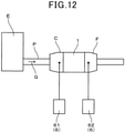
- the exhaust gas purification filter 1 was attached inside an exhaust pipe P of a 2.0 L, naturally aspirated, four-cylinder, gasoline direct-injection engine E. Specifically, a ceramic mat (not shown) was wrapped around the exhaust gas purification filter 1, and the exhaust gas purification filter 1 was inserted into a filter case C.
- the filter case C was connected to the exhaust pipe P of the engine E with a fitting cone F therebetween, and the exhaust gas G was sent to the exhaust gas purification filter 1 from the engine E.
- a value of A/F that is, an air-fuel ratio: air / fuel
- a NOx concentration in the exhaust gas G was measured by a gas concentration meter 7 under conditions that an intake air amount is 10 g/s and a rotation speed of the engine E is 1500 rpm.
- a first gas concentration meter 71 for measuring the NOx concentration on an entrance side before the exhaust gas G flows into the exhaust gas purification filter 1 and a second gas concentration meter 72 for measuring the NOx concentration on an exit side on which the exhaust gas G flows out from the exhaust gas purification filter 1 were used.
- the first gas concentration meter 71 and the second gas concentration meter 72 are both "MEXA-7500" manufactured by Horiba, Ltd.
- A/F sensor 8 a first A/F sensor 81 for measuring an A/F concentration on the entrance side before the exhaust gas G flows into the exhaust gas purification filter 1 and a second A/F sensor 82 for measuring the A/F concentration on the exit side on which the exhaust gas G flows out from the exhaust gas purification filter 1 were used.
- A/F: 14.4 is an A/F value that is most frequent in Worldwide-harmonized Light vehicles Test Cycle (WLTC) mode traveling.
- WLTC Worldwide-harmonized Light vehicles Test Cycle
- an exhaust gas temperature may reach a high-temperature region of 750°C or higher.
- the exhaust G was sent to the exhaust gas purification filter 1 from the engine E.
- a PM concentration on the entrance side before the exhaust gas G flows into the exhaust gas purification filter 1 and a PM concentration on the exit side on which the exhaust gas G flows out from the exhaust gas purification filter 1 were measured by a PM sensor 6.
- Measurement conditions were a temperature of 720°C and an exhaust-gas flow amount of 11.0 m 3 /min.
- Example 1 Average pore diameter ( ⁇ m) Gas permeability coefficient ( ⁇ 10 12 m 2 ) Pore volume ratio of pore diameters of 9 ⁇ m or less (%) GSA ( ⁇ m 2 / ⁇ m 3 ) Average thickness of catalyst layer ( ⁇ m) NOx reduction efficiency (%) Collection efficiency (%)
- Example 1 64 21.4 1.73 13 108056 5.0 96.2 73.0
- Example 2 64 27.0 3.50 12 95962 5.2 97.6 65.0
- Example 3 64 18.4 3.20 14 130945 5.2 97.4 69.2
- Example 4 64 26.0 2.02 20 93016 5.1 97.2 67.2
- Example 5 64 18.0 1.20 4 98132 5.4 86.0 73.0
- Example 6 64 18.0 0.80 12 88245 5.0 95.6 75.2
- Example 7 64 18.0 0.41 16 86849 3.9 90.8 81.6
- Example 8 64 12.2 0.35 17 85437 5.8
- Example 9 64 14.6 0.37 19 71004 4.4 85.3 77.4
- the exhaust gas purification filters 1 of the examples have a gas permeability coefficient that is equal to or greater than 0.35 ⁇ 10 -12 m 2 , a pore volume ratio of pore diameters of 9 ⁇ m or less that is equal to or less than 25%, and an average pore diameter that is equal to or greater than 12 ⁇ m. Therefore, the NOx reduction efficiency is high in the examples. From a perspective of satisfying a reduction efficiency required as a U/F catalytic converter in a typical direct-injection engine, the NOx reduction efficiency is preferably equal to or greater than 80%.
- the U/F catalytic converter is also referred to as an under-floor catalyst. The U/F catalytic converter will be described according to a second embodiment.
- the gas permeability coefficient is equal to or greater than 0.35 ⁇ 10 -12 m 2 .
- the gas permeability coefficient is preferably equal to or greater than 0.40 ⁇ 10 -12 m 2 and more preferably equal to or greater than 0.80 ⁇ 10 -12 m 2 .
- the average pore diameter is equal to or greater than 12 ⁇ m.
- the average pore diameter is more preferably equal to or greater than 14 ⁇ m.
- the pore volume ratio of pore diameters of 9 ⁇ m or less is equal to or less than 25%.
- the pore volume ratio of pore diameters of 9 ⁇ m or less is preferably equal to or less than 20% and more preferably equal to or less than 15%.
- a reason for this is thought to be that, when the pore volume ratio of pore diameters of 9 ⁇ m or less is reduced, the pores 121 that exceed the pore diameter of 9 ⁇ m increase, and the catalyst layer 17 is thinly and widely formed by the catalyst being supported.
- the pore volume ratio of pore diameters of 9 ⁇ m or less is preferably equal to or greater than 3%, more preferably equal to or greater than 10%, and even more preferably equal to or greater than 15%.
- the pores 121 that have a pore diameter of 9 ⁇ m or less contribute greatly to the improvement of PM collection efficiency. Therefore, when the pores 121 that have a pore diameter of 9 ⁇ m or less are too few, PM collection performance may decrease.
- the NOx reduction efficiency further improves when the pore wall area per unit volume (that is, the GSA) of the partition wall 12 is equal to or greater than 70000 ⁇ m 2 / ⁇ m 3 .
- the GSA is more preferably equal to or greater than 85000 ⁇ m 2 / ⁇ m 3 , and even more preferably equal to or greater than 90000 ⁇ m 2 / ⁇ m 3 .
- an S/C catalyst 1A (that is, a start catalyst) is arranged inside the exhaust pipe P, on an upstream side in a flow direction of the exhaust gas G that is discharged from the engine E.
- the S/C catalyst 1A may be a honeycomb structure that is formed from cordierite. Although an illustration of the configuration of the S/C catalyst 1A is omitted, the S/C catalyst 1A has a shape that is similar to the honeycomb structure portion 10 according to the first embodiment. Specifically, the S/C catalyst 1A includes the outer shell 11, the partition walls 12, and the cells 13, but does not include the plug portions.
- the honeycomb structure used in the S/C catalyst 1A is also referred to as a monolithic carrier. A three-way catalyst is supported in partition walls 12.
- the exhaust gas purification filter 1 that includes the honeycomb structure portion 10 and the plug portions 16 can also be used.
- a U/F catalytic converter IB (that is, an under-floor catalytic converter) is arranged in a U/F position (that is, an under-floor position) that is under a floor of the vehicle downstream of the S/C catalyst 1A.
- a U/F position that is, an under-floor position
- the U/F catalytic converter IB is also commonly referred to as a second converter.
- the S/C catalyst 1A and the U/F catalytic converter IB are respectively inserted into differing cases C1 and C2, and the cases C1 and C2 are connected to the exhaust pipe P. On a path of the exhaust pipe P, the S/C catalyst 1A and the U/F catalytic converter IB are arranged a predetermined distance apart.
- a tandem-type catalytic unit may be configured using the exhaust gas purification filter 1.
- the S/C catalyst 1A and a rear catalyst 1C are inserted into the same case C3, and the case C3 is connected to the exhaust pipe P.
- the exhaust gas purification filter 1 according to the first embodiment may be used as the rear catalyst 1C.
- the exhaust gas purification filter 1 is used as the U/F catalytic converter 1B, the rear catalyst 1C of the tandem-type catalytic unit, and the like, and is used on the downstream side of the S/C catalyst 1A that supports a three-way catalyst.
- toxic gas components such as CO, HC, and NOx are reduced by the three-way catalyst. Because the exhaust gas temperature is high, CO and HC are sufficiently reduced in the S/C catalyst 1A.
- the NOx that had not been sufficiently reduced by the S/C catalyst 1A is mainly reduced.
- the exhaust gas purification filter 1 according to the first embodiment has excellent NOx purification performance, the exhaust gas purification filter 1 is suitable for the U/F catalytic converter 1B and the rear catalyst 1C of the tandem-type catalytic unit that are arranged on the downstream side of the S/C catalyst 1A.
- the exhaust gas purification filter 1 is used to purify the exhaust gas G of an internal combustion engine such as a diesel engine or a gasoline engine
- the exhaust gas purification filter 1 may be suitable for application regarding emissions from a gasoline engine. That is, the exhaust gas purification filter 1 is preferably a gasoline particulate filter.
- the gasoline particulate filter is referred to as a GPF.
- the GPF requires not only PM purification performance, but also purification of toxic gas substances by being coated with a purification catalyst for toxic gas components such as NOx.
Landscapes
- Chemical & Material Sciences (AREA)
- Engineering & Computer Science (AREA)
- Chemical Kinetics & Catalysis (AREA)
- Materials Engineering (AREA)
- Organic Chemistry (AREA)
- Ceramic Engineering (AREA)
- Manufacturing & Machinery (AREA)
- Combustion & Propulsion (AREA)
- Structural Engineering (AREA)
- Mechanical Engineering (AREA)
- General Engineering & Computer Science (AREA)
- Geometry (AREA)
- Physics & Mathematics (AREA)
- Inorganic Chemistry (AREA)
- Health & Medical Sciences (AREA)
- Toxicology (AREA)
- Oil, Petroleum & Natural Gas (AREA)
- General Chemical & Material Sciences (AREA)
- Analytical Chemistry (AREA)
- Environmental & Geological Engineering (AREA)
- Biomedical Technology (AREA)
- Exhaust Gas Treatment By Means Of Catalyst (AREA)
- Catalysts (AREA)
- Processes For Solid Components From Exhaust (AREA)
- Exhaust Gas After Treatment (AREA)
- Nanotechnology (AREA)
Abstract
Description
- The present application is based on and claims the benefit of priority from
Japanese Patent Application No. 2019-086489, filed on April 26, 2019 - The present disclosure relates to an exhaust gas purification filter that is used so as to support a NOx purification catalyst.
- Exhaust gas that is discharged from internal combustion engines, such as diesel engines and gasoline engines, and heat engines, such as boilers, contains particulate matter referred to as particulates. The particulates are referred to, hereafter, as "PM", as appropriate. An exhaust gas purification filter is used to collect the PM in the exhaust gas.
- The exhaust gas purification filter typically has a plurality of cells that are formed so as to be partitioned by porous partition walls and a plug portion that seals either of both ends of the cell. The exhaust gas purification filter is required to collect the PM that is contained in the exhaust gas inside pores in the partition walls, while reducing pressure loss. Here, pressure loss is referred to hereafter, as "pressure loss", as appropriate.
- For example,
PTL 1 discloses a filter that has a porosity of 45 to 70%, a predetermined average pore diameter difference rate of 35% or less, an average pore diameter of 15 to 30 µm, and a maximum pore diameter of 150 µm or less, measured by a bubble point method. Based onPTL 1, pressure loss during PM accumulation can be reduced through use of the above-described configuration. - [PTL 1]
Japanese Patent Publication No. 4473693 - In recent years, there has been demand for the exhaust gas purification filter to be provided with purification performance regarding toxic substances such as NOx. For example, the exhaust gas purification filter may support a NOx purification catalyst. NOx has a slow diffusion rate in a catalyst layer. Therefore, rather than a catalyst layer being thickly formed, the amount of NOx is more effectively reduced by the same amount of the catalyst layer being thinly and widely formed. However, in a conventional exhaust gas purification filter such as that described in
PTL 1, a narrow portion is formed in a pore in which the catalyst is supported. Flow path resistance of a catalyst slurry increases, and the catalyst layer tends to be formed so as to be partially thick as a result of the catalyst being supported. Therefore, there is room for further improvement in purification performance regarding NOx in the catalyst layer of the conventional exhaust gas purification filter. - The present disclosure provides an exhaust gas purification filter that is capable of exhibiting excellent NOx purification performance by supporting a catalyst.
- An aspect of the present disclosure is an exhaust gas purification filter that is used so as to support a NOx purification catalyst. The exhaust gas purification filter includes: a honeycomb structure portion that includes a partition wall in which numerous pores are formed, and a plurality of cells that are partitioned by the partition walls and form a flow path for an exhaust gas; and a plug portion that alternately seals an inflow end surface or an outflow end surface for the exhaust gas in the cells. The partition wall has a gas permeability coefficient that is equal to or greater than 0.35 × 10⁻¹² m2, a pore volume ratio of pore diameters of 9 µm or less that is equal to or less than 25%, and an average pore diameter that is equal to or greater than 12 µm.
- In the above-described exhaust gas purification filter, the gas permeability coefficient of the partition wall, the pore volume ratio of pore diameters of 9 µm or less of the partition wall, and the average pore diameter of the partition wall are adjusted as described above. In such a partition wall, because flow path resistance of the pores is small, a catalyst layer is thinly and widely formed by the NOx purification catalyst being supported. As a result, NOx that has a slow diffusion rate is efficiently reduced. Consequently, high NOx reduction efficiency is exhibited by the NOx purification catalyst being supported.
- As described above, according to the above-described aspect, the exhaust gas purification filter that is capable of exhibiting excellent NOx purification performance by supporting a catalyst can be provided.
- Reference numbers within the parentheses in the scope of claims indicate corresponding relationships with specific means according to embodiments described hereafter, and do not limit the technical scope of the present disclosure.
-
-
Fig. 1 is a perspective view of an exhaust gas purification filter according to a first embodiment; -
Fig. 2 is an enlarged cross-sectional view in an axial direction of the exhaust gas purification filter according to the first embodiment; -
Fig. 3 is an enlarged cross-sectional schematic diagram of a partition wall according to the first embodiment; -
Fig. 4 is an enlarged cross-sectional schematic diagram of a pore wall on which a NOx purification catalyst is supported according to the first embodiment; -
Fig. 5(a) is a schematic diagram of a simplified cross-section of the partition wall according to the first embodiment, andFig. 5(b) is a schematic diagram of a simplified cross-section of the partition wall on which the NOx purification catalyst is supported according to the first embodiment; -
Fig. 6 is a schematic diagram of arrangement patterns of raw material particles according to the first embodiment; -
Fig. 7(a) is a schematic diagram of a simplified cross-section of a partition wall on which a small amount of an HC purification catalyst is supported in a comparative example 1, andFig. 7(b) is a schematic diagram of a simplified cross-section of a partition wall on which a large amount of the HC purification catalyst is supported in the comparative example 1; -
Fig. 8(a) is a schematic diagram of an outer shape of the exhaust gas purification filter in an experiment example 1,Fig. 8(b) is a schematic diagram (specifically, a cross-sectional view taken along line VIIIb-VIIIb inFig. 8(c) ) of a sampling position of a measurement sample in a radial direction of the exhaust gas purification filter in the experiment example 1, andFig. 8(c) is a schematic diagram of sampling positions of measurement samples in an axial direction and the radial direction of the exhaust gas purification filter in the experiment example 1; -
Fig. 9 is a graph of an example of a relationship between gas flow rate and pressure loss ΔP in the experiment example 1; -
Fig. 10 is a diagram of a threshold for a binarization process in 3D modeling in the experiment example 1; -
Fig. 11 is a schematic diagram of a configuration of a measurement apparatus for NOx reduction efficiency in the experiment example 1; -
Fig. 12 is a schematic diagram of a configuration of a measurement apparatus for PM collection efficiency in the experiment example 1; -
Fig. 13 is a graph of a relationship between a gas permeability coefficient and NOx reduction efficiency in the experiment example 1; -
Fig. 14 is a graph of a relationship between pore volume ratio of pore diameters of 9 µm or less and NOx reduction efficiency in the experiment example 1; -
Fig. 15 is a graph of a relationship between average pore diameter and NOx reduction efficiency in the experiment example 1; and -
Fig. 16(a) is a schematic diagram of an example of an arrangement configuration of an exhaust gas purification filter according to a second embodiment andFig. 16(b) is a schematic diagram of another example of the arrangement configuration of the exhaust gas purification filter according to the second embodiment. - An embodiment of an exhaust
gas purification filter 1 will be described with reference toFigs. 1 to 6 . As shown inFig. 1 , the exhaustgas purification filter 1 includes ahoneycomb structure portion 10 and aplug portion 16. For example, thehoneycomb structure portion 10 may be made of by a ceramic, such as cordierite, and includes anouter shell 11, apartition wall 12, and acell 13. - As shown in
Figs. 1 and 2 , for example, theouter shell 11 may be a cylindrical body. For example, a specific shape of theouter shell 11 may be a circular cylinder of which a cross-sectional shape in a direction orthogonal to an axial direction Y of theouter shell 11 is a circle. However, the shape of theouter shell 11 may be a polygonal cylinder of which the cross-sectional shape is a polygon, such as a square. According to the present embodiment, the axial direction Y of this cylindricalouter shell 11 is described as the axial direction Y of the exhaustgas purification filter 1. The axial direction Y of the exhaust gas purification filter is referred to, as appropriate, as a filter axial direction Y. In addition, arrows inFig. 2 indicate a flow of exhaust gas G when the exhaustgas purification filter 1 is arranged on a path of the exhaust gas G, such as in an exhaust pipe. - The
partition walls 12 partition an interior of theouter shell 11 intonumerous cells 13. Thepartition wall 12 is also commonly referred to as a cell wall. For example, thepartition walls 12 may be provided in a lattice shape. The exhaustgas purification filter 1 is a porous body. As shown inFig. 3 ,numerous pores 121 are formed in thepartition wall 12. Therefore, the exhaustgas purification filter 1 is capable of accumulating and collecting PM that is contained in the exhaust gas G on a surface of thepartition wall 12 and inside thepore 121. Thepore 121 is also commonly referred to as a pore. The PM is fine particles that are referred to as particulate substance, particulate matter, particulates, and the like. Theouter shell 11 and thepartition wall 12 are integrally formed. - As shown in
Figs. 1 and 2 , the exhaustgas purification filter 1 includesnumerous cells 13. Thecell 13 is surrounded by thepartition walls 12 and forms a flow path for the exhaust gas G. An extending direction of thecell 12 ordinarily coincides with the filter axial direction Y. - For example, a cell shape on a filter cross-section in a direction orthogonal to the filter axial direction Y may be a square. However, this is not limited thereto. The cell shape may be a polygon such as a triangle, a square, or a hexagon, a circle, or the like. In addition, the cell shape may be a combination of two or more differing types of shapes.
- The exhaust
gas purification filter 1 is used so as to support (carry) a NOx purification catalyst. That is, the exhaustgas purification filter 1 before a catalyst is supported may be a substrate for supporting the NOx purification catalyst. The NOx purification catalyst is supported on at least thepartition wall 12. The exhaustgas purification filter 1 may have a support surface for supporting the NOx purification catalyst on thepartition wall 12. For example, the support surface may be a flow path surface 125 and apore wall surface 124a shown inFigs. 2 to 5 . The flow path surface 125 is a portion in which thepartition wall 12 faces thecell 13. Thepore wall surface 124a is a portion in which apore wall 124 faces thepore 121. The NOx purification catalyst is supported on thepartition wall 12 as acatalyst layer 17. - For example, the exhaust
gas purification filter 1 may be a columnar body that has a circular columnar shape or the like, and dimensions thereof can be changed as appropriate. The exhaustgas purification filter 1 has aninflow end surface 14 and anoutflow end surface 15 on both ends in the filter axial direction Y. Theinflow end surface 14 is an end surface on a side on which the exhaust gas G flows in in a state in which the exhaustgas purification filter 1 is arranged in the flow of the exhaust gas G, and theoutflow end surface 15 is an end surface on a side on which the exhaust gas G flows out. - In a state in which the exhaust
gas purification filter 1 is not arranged in the flow of the exhaust gas G, theinflow end surface 14 and theoutflow end surface 15 refer to relative surfaces in the filter axial direction Y. That is, when either of the end surface is theinflow end surface 14, the other is theoutflow end surface 14. For example, theinflow end surface 14 can also be referred to as a first end surface and theoutflow end surface 15 may be referred to as a second end surface. - The exhaust
gas purification filter 1 includes aplug portion 16. For example, theplug portions 16 may seal theinflow end surface 14 or theoutflow end surface 15 of thecells 13 in an alternating manner. For example, theplug portion 16 may be made of a ceramic, such as cordierite. However, other materials are also possible. - In
Fig. 2 , a plug-shapedplug portion 16 is formed. However, the shape of theplug portion 16 is not particularly limited as long as theinflow end surface 14 or theoutflow end surface 15 can be sealed. Here, although an illustration of a configuration is omitted, for example, theplug portion 16 can also be formed by a portion of thepartition wall 12 being deformed on theinflow end surface 14 or theoutflow end surface 15. In this case, because theplug portion 16 is formed by a portion of thepartition wall 12, thepartition wall 12 and theplug portion 16 are integrally and continuously formed. - For example, as the
cells 13, afirst cell 131 and asecond cell 132 may be provided. As shown inFig. 2 , for example, in thefirst cell 131, theinflow end surface 14 that serves as an inflow side for the exhaust gas G may be open and theoutflow end surface 15 may be sealed by theplug portion 16. For example, in thesecond cell 132, theoutflow end surface 15 that serves as an outflow side for the exhaust gas G may be open and theinflow end surface 14 may be sealed by theplug portion 16. - For example, the
first cells 131 and thesecond cells 132 may be formed in an alternately arrayed manner, so as to be adjacent to each other in a lateral direction X that is orthogonal to the filter axial direction Y and a vertical direction Z that is orthogonal to both the filter axial direction Y and the lateral direction X. That is, when theinflow end surface 14 or theoutflow end surface 15 of the exhaustgas purification filter 1 is viewed from the filter axial direction Y, for example, thefirst cells 131 and thesecond cells 132 may be arranged in a checkered pattern. - As shown in
Fig. 2 , thepartition walls 12 separate thefirst cell 131 and thesecond cell 132 that are adjacent to each other. As shown inFig. 3 , inside thepartition wall 12,numerous pores 121 are formed by thepore walls 124. Thepores 121 include a communicating pore 121c that communicates between thefirst cell 131 and thesecond cell 132, and a non-communicating pore (not shown) that does not communicate therebetween. For example, the communicating pore 121c may be confirmed through electron microscope observation of a partition wall cross-section by a scanning electron microscope or the like. - In
Fig. 3 , thepores 121 are shown so as to be simplified into a two-dimensional form. However, it is though that most of thepores 121 intersect in a three-dimensional manner. Thepores 121 serve as paths for the exhaust gas G inside thepartition wall 12. As a result of the exhaust gas G passing through thepores 121, the PM in the exhaust gas G is collected on thepore wall surfaces 124a. In addition, as a result of thepore walls 124 supporting the NOx purification catalyst, toxic gas components such as NOx that are contained in the exhaust gas G that passes through thepores 121 are reduced by the NOx purification catalyst. Thecells 13 also serve as paths for the exhaust gas G in a manner similar to thepores 121. The PM is also collected on the flow path surfaces 125 of thepartition walls 12. As a result of the flow path surfaces 125 supporting the NOx purification catalyst, the NOx is also reduced on the flow path surfaces 125. - As shown in
Fig. 4 , for example, thecatalyst layer 17 may be formed on thepore wall surface 124a of thepartition wall 12. Thecatalyst layer 17 may be formed in a continuous manner or a non-continuous manner. For example, thecatalyst layer 17 may be also formed on the flow path surface 125 of thepartition wall 12. - As a result of the communicating pores being increased as appropriate, reduction of pressure loss and improvement in PM collection efficiency can both be achieved. Pressure loss is referred to, hereafter, as "pressure loss", as appropriate. A quantity, shape, and the like of the communicating pores can be adjusted with porosity, average pore diameter, and the like as indicators. From a perspective of appropriately increasing the communicating pores and from a perspective of maintaining strength of the exhaust
gas purification filter 1, the porosity is preferably 50 to 70%, more preferably 55 to 65%, and even more preferably 60 to 65%. The porosity is measured based on principles of a mercury injection method, as described in an experiment example. - The
catalyst layer 17 contains the NOx purification catalyst. As the NOx purification catalyst, a three-way catalyst that is composed of precious metals, such as Pt, Rh, and Pd may be used. In this case, the NOx purification catalyst can further purify toxic gas components such as CO and HC, in addition to NOx. Thecatalyst layer 17 may also further contain alumina, an auxiliary catalyst, and the like. As the auxiliary catalyst, ceria, zirconia, a ceria-zirconia solid solution, and the like may be used as examples. - A formation method for the
catalyst layer 17 is not particularly limited. However, for example, a method in which thepartition wall 12 is impregnated with a fluid that contains a catalyst such as a noble metal and baked may be common. For example, the fluid may be a liquid such as a catalyst slurry. - Because the diffusion rate of NOx in the catalyst layer is slow, when the catalyst layer is thick, diffusion of NOx in the catalyst layer is insufficient. NOx reduction efficiency increases by the
catalyst layer 17 being thinly and widely formed on thepore wall surfaces 124a and the like. A reason for this is as follows. - For example, when a predetermined amount of the
catalyst layer 17 is formed in the exhaustgas purification filter 1, as a result of thecatalyst layer 17 being thinly formed, thecatalyst layer 17 is formed in a wide area of thepore walls 124. Therefore, in the exhaustgas purification filter 1, contact frequency between thecatalyst layer 17 and the NOx increases, and the NOx is more easily reduced. - In addition, because the diffusion rate of NOx in the
catalyst layer 17 is slow, purification may be sufficiently performed even when thickness of thecatalyst layer 17 is small. During catalyst layer formation, thepore 121 forms flow paths for a fluid such as the catalyst slurry. As a result of the flow path resistance thereof being reduced, the fluid flows more easily, and thecatalyst layer 17 is thinly and widely formed. - For example, to reduce the flow path resistance, increasing the pore diameter in the
narrow portion 127 of thepore 121, increasing an average pore diameter, or increasingpores 121 that have a large pore diameter is effective. Thenarrow portion 127 is a portion in which the pore diameter is smaller than that in the periphery. For example, thenarrow portion 127 may be a narrowed portion of thepore 121 on a partition wall cross-section in a wall thickness direction. As a result of thenarrow portion 127 being increased, a gas permeability coefficient of thepartition wall 12 can be increased. In addition, as a result of thepores 121 that have a small pore diameter being reduced, thepores 121 that have a large pore diameter can be increased. - To sufficiently improve the NOx reduction efficiency by thinly and widely forming the
catalyst layer 17, it is effective to increase the gas permeability coefficient of thepartition wall 12 to be equal to or greater than a predetermined value, increase the average pore diameter to be equal to or greater than a predetermined value, and reduce thepores 121 that have a small pore diameter to be equal to or less than a predetermined value. Specifically, as a result of the gas permeability coefficient being equal to or greater than 0.35 × 10⁻¹² m2, the average pore diameter being equal to or greater than 12 µm, and a pore volume ratio of pore diameters of 9 µm or less than being equal to or less than 25%, the NOx reduction efficiency can be sufficiently increased. - In addition, as a result of the flow path resistance being reduced, the
catalyst layer 17 can be thinly formed in a wider area even with the same coating amount. Therefore, because the NOx reduction efficiency can be improved without the coating amount of thecatalyst layer 17 being increased, the NOx reduction efficiency can be improved while increase in pressure loss is suppressed. In addition, the NOx purification performance after a catalyst is supported can be improved by pore control of the exhaustgas purification filter 1 that serves as a carrier for the NOx purification catalyst. - For example, the
catalyst layer 17 may be thinly and widely formed on thepore wall surfaces 124a and the like by the above-described common formation method using a catalyst slurry, and the exhaustgas purification filter 1 after a catalyst is supported exhibits excellent NOx purification performance. Measurement and calculation methods for the gas permeability coefficient, the average pore diameter, and the pore volume ratio are described in the experiment example. The pore volume ratio refers to a proportion of a volume of thepores 121 that have a predetermined pore diameter in relation to an overall pore volume, and is calculated from a pore diameter distribution that is measured based on the principles of the mercury injection method as described in the experiment example. - From a perspective of suppressing worsening of the PM collection efficiency, the gas permeability coefficient is preferably equal to or less than 3.0 × 10⁻¹² m2, more preferably equal to or less than 2.5 × 10⁻¹² m2, and even more preferably equal to or less than 2.0 × 10⁻¹² m2, When the gas permeability coefficient is too high, the exhaust gas easily slips through inside the
partition wall 12, and the collection efficiency is thought to become worse because more PM contained in the exhaust gas also slips through. From a similar perspective, the average pore diameter is preferably equal to or less than 25 µm, more preferably equal to or less than 23 µm, and even more preferably equal to or less than 20 µm. Because the PM more easily slips through when the average pore diameter is too large as well, the collection efficiency is thought to worsen. - A pore wall area per unit volume of the
partition wall 12 is preferably equal to or greater than 70000 µm2/µm3. In this case, an area of thepore wall surface 124a that serves as the support surface on which the catalyst layer is formed is sufficiently large. Therefore, for example, when the same amount of catalyst is supported, the catalyst layer may be more thinly and widely formed. Consequently, the NOx that has a slow diffusion rate is efficiently reduced in the catalyst layer and the reduction efficiency is improved. - From a perspective of improving the NOx reduction efficiency, the pore wall area per unit volume of the
partition wall 12 is more preferably equal to or greater than 85000 µm2/µm3, and even more preferably equal to or greater than 90000 µm2/µm3. Meanwhile, from a perspective of further improving the NOx reduction efficiency, the pore wall area per unit volume of thepartition wall 12 is preferably equal to or less than 200000 µm2/µm3, more preferably equal to or less than 190000 µm2/µm3, and even more preferably equal to or less than 180000 µm2/µm3. - A reason for this is that, although the catalyst layer being thinly and widely formed as described above is advantageous in improving the NOx reduction efficiency, from a perspective of sufficiently maintaining a diffusion distance (specifically, a reaction time) of the NOx, having a certain degree of thickness is thought to be advantageous. The pore wall area is an area of the
pore wall surface 124a and is an area of a portion in which thepore wall 124 that forms thepore 121 faces thepore 121. For example, the pore wall area may also be referred to as a geometric surface area inside thepartition wall 12. The pore wall area is referred to, hereafter, as "GSA", as appropriate. A measurement method for the GSA is described in the experiment example. - For example, the
catalyst layer 17 may be formed in the exhaustgas purification filter 1. A supported amount of thecatalyst layer 17 is preferably 30 to 150 g/L. In this case, sealing of thepores 121 by thecatalyst layer 17 is suppressed while required purification performance is ensured. - An average thickness of the
catalyst layer 17 is preferably equal to or less than 6 µm. In this case, NOx purification is more efficiently performed in thecatalyst layer 17. A reason for this is that, for example, when a predetermined amount of thecatalyst layer 17 is formed, thecatalyst layer 17 may be formed in a wider area of thepore wall surface 124a when thecatalyst layer 17 is formed with a small thickness, such as 6 µm, than when thecatalyst layer 17 is formed with a large thickness. In the purification of NOx of which the diffusion speed is slow, thecatalyst layer 17 being thinly and widely formed, rather than thickly and narrowly formed, is more advantageous. - As described above, NOx purification can be sufficiently efficiently performed as a result of the average thickness of the
catalyst layer 17 being equal to or less than 6 µm. Therefore, the NOx purification performance further improves. From a perspective of further improving the NOx purification performance, the average thickness of thecatalyst layer 17 is more preferably equal to or less than 5 µm. In addition, when the thickness of thecatalyst layer 17 is too thin, from a perspective of risk of decrease in the NOx purification performance, the average thickness of thecatalyst layer 17 is preferably equal to or greater than 2 µm. For example, the average thickness of thecatalyst layer 17 can be adjusted by an amount of the catalyst slurry that is used during formation of thecatalyst layer 17. - For example, the exhaust
gas purification filter 1 according to the present embodiment may be manufactured in the following manner. First, a green body that contains cordierite formation raw materials is fabricated. The green body is fabricated by silica, talc, aluminum hydroxide, and the like being adjusted to form a cordierite composition, a binder such as methyl cellulose, a pore-forming material such as graphite, a lubricating oil, water, and the like being added as appropriate and mixed. Alumina and kaolin may be added to form the cordierite composition. As the silica, porous silica may be used. - In the cordierite formation raw materials, silica and talc may be pore formation
raw materials 101. The pore formationraw material 101 is a material that forms thepores 121. The pore formationraw materials 101 produce a liquid phase component during firing, and thepores 121 are formed as a result. Meanwhile, in the cordierite formation raw materials, aluminum hydroxide, alumina, and kaolin may be aggregateraw materials 102. The aggregateraw material 102 is a material that forms a ceramic portion other than thepores 121. - Next, the green body is molded, dried, and fired. As a result, the
honeycomb structure portion 10 is formed. Thehoneycomb structure portion 10 is a portion that is configured by theouter shell 11, thepartition walls 12, and thecells 13. Theplug portions 16 are formed after firing of thehoneycomb structure portion 10 or before firing. Specifically, for example, theplug portions 16 may be formed by the end surfaces of thecells 13 in thehoneycomb structure portion 10 after firing or a honeycomb-structured molded body before firing being alternately sealed using a slurry for formation of the plug portion and fired. - The
catalyst layer 17 is formed in thehoneycomb structure portion 10 before the formation of theplug portions 16 or thehoneycomb structure portion 10 after the formation of theplug portions 16. Thecatalyst layer 17 is formed by thepartition walls 12 being impregnated with the catalyst slurry that contains a noble metal, alumina, an auxiliary catalyst, and the like, and a solid component of the slurry being burned into thepartition walls 12. During impregnation, for example, suction may be applied. - According to the present embodiment, because the gas permeability coefficient, the average pore diameter, and the pore volume ratio of pore diameters of 9 µm or less are adjusted to predetermined ranges, the flow path resistance of the catalyst slurry decreases. Therefore, the
catalyst layer 17 is thinly and widely formed without the amount of catalyst being changed. As a result, the NOx that has a slow diffusion rate is efficiently reduced. To reduce the flow path resistance, for example, thenarrow portion 127 may be made larger in the following manner. - In the molded body during firing, for example, it may be thought that there are portions in which the pore formation
raw materials 101 and the aggregateraw materials 102 are arranged in patterns shown in A to E inFig. 6 . - Pattern A and pattern C are cases in which a plurality of pore formation
raw materials 101a that have a large grain size are close to each other. Pattern B is a case in which the pore formationraw materials 101a that have a large grain size and pore formationraw materials 101b that gave a small grain size are in contact. Pattern D and pattern E are cases in which the pore formationraw materials 101 are not in contact with each other, and the aggregateraw materials 102 are arranged between the pore formationraw materials 101. In pattern D, aggregateraw materials 102a that have a large grain size are arranged between the pore formationraw materials 101. In pattern E, aggregateraw materials 102b that have a small grain size are arranged between the pore formationraw materials 101. - When cases in which the
narrow portion 127 is formed by the patterns of raw material arrangement shown as examples inFig. 6 are assumed, a size of thenarrow portion 127 is as follows. As a result of the pore formationraw materials 101 being placed in contact with each other as shown in patterns A to C, thenarrow portion 127 is enlarged and the largenarrow portion 127 can be formed. Meanwhile, when the pore formationraw materials 101 and the aggregateraw materials 102 are placed in contact as shown in patterns D and E, thenarrow portion 127 becomes small. For example, a medium-sizednarrow portion 127 may be formed in pattern D and a small-sizednarrow portion 127 is formed in pattern E. - Therefore, as a result of a contact pattern between the pore formation
raw materials 101 and the aggregateraw materials 102 being controlled, the size of thenarrow portion 127 can be adjusted. Specifically, through use of at least two types of pore formationraw materials 101 that have opposite positive and negative electric charges from each other, thepore formation materials 101 are more easily placed in contact with each other as in patterns A to C. - Therefore, the
narrow portion 127 can be made larger. More specifically, for example, the pore formationraw materials 101 may be silica and talc. Silica can be imparted a positive (+) charge and talc can be imparted a negative (-) charge. The positive and negative may be interchanged therebetween. In addition, a portion of a mixture of silica and talc may be imparted a positive (+) charge and a portion or an entirety of the remaining mixture may be imparted a negative (-) charge. Electric charge may be imparted to all pore formationraw materials 101 used in the manufacture of the exhaustgas purification filter 1. Alternatively, a portion of the pore formationraw materials 101 may be imparted electric charge. - For example, to impart electric charge, an anionic dispersant or a cationic dispersant may be used. Specifically, the pore formation
raw material 101 and the dispersant are mixed in advance. Mixing of the pore formationraw material 101 and the dispersant is referred to as pre-kneading. As a result of pre-kneading, the dispersant is attached to the pore formationraw material 101 and the pore formationraw material 101 is charged. A positively charged pore formationraw material 101 and a negatively charged pore formationraw material 101 are obtained. After pre-kneading, the pore formationraw material 101 to which the dispersant is attached, the aggregateraw material 102, and other raw materials are further mixed. - When a pre-kneading time is too long, connectivity between the
pores 121 may be lost. Therefore, the pre-kneading time is preferably appropriately adjusted. In addition, when the grain size of the aggregateraw materials 102 surrounding the pore formationraw materials 101 increases, connectivity between thepores 121 may be lost. Therefore, a grain size ratio between the pore formationraw materials 101 and the aggregateraw materials 102 is also preferably appropriately adjusted. - The gas permeability coefficient, the average pore diameter, and the pore volume ratio of pore diameters of 9 µm or less can be controlled to the above-described desired ranges by the grain size ratio of the pore formation
raw materials 101 and the aggregateraw materials 102, a type of the dispersant, an added amount of the dispersant, the pre-kneading time, rotation speed during extrusion, a drying time of clay, and the like being adjusted. - Next, an exhaust gas purification filter that has a narrow portion that has a small pore diameter will be described with reference to
Fig. 7. Fig. 7 shows apartition wall 92 of the exhaust gas filter of the present example.Figs. 7(a) to (c) schematically shows communicating pores (that is, pores 911, 912, and 913) of thepartition wall 92 with simplified shapes. - As shown in
Fig. 7(a) , in thepartition wall 92 of the exhaust gas purification filter,various pores type pore 911 that has a large pore diameter and anarrow portion 917 that has a small pore diameter; apore 912 that has a medium-sized pore diameter, and apore 913 that has a small-sized pore diameter. - For example, when a predetermined amount of a
catalyst layer 97 is formed on thepartition wall 92 using a catalyst slurry, as shown inFig. 7(b) , in thenarrow portion 917 that has a high flow path resistance, thecatalyst layer 97 that is partially thicker than that in the periphery may be formed. Meanwhile, in thepore 913 that has a small pore diameter, because the flow path resistance is high, the catalyst slurry does not easily enter thepore 913, and thecatalyst layer 97 is difficult to form. Because thepore 913 that has a small pore diameter is advantageous for collection of PM, the PM collection efficiency increases by the small-sized pores being increased. However, the NOx purification performance after thecatalyst layer 97 is supported decreases. - In addition, as shown in
Fig. 7(c) , as a result of the supported amount of the catalyst being increased, thecatalyst layer 97 can be formed in thepore 913 that has a small pore diameter. However, in this case, manufacturing cost increases by an amount of increase in the catalyst. Furthermore, in this case, because thenarrow portions 917 and the medium-sized pores 912 are at least partially sealed by thecatalyst layer 97, pressure loss increases. - In a present example, as shown in Table 1, a plurality of exhaust
gas purification filters 1 that have differing average pore diameters, gas permeability coefficients, and pore volume ratios of pore diameters of 9 µm or less are manufactured. In addition, thecatalyst layer 17 that contains the NOx purification catalyst is formed on thepartition walls 12 of the exhaustgas purification filters 1, and the NOx reduction efficiency, the PM collection efficiency, and the like are compared and evaluated. - Here, reference numbers used in the experiment example 1 and subsequent thereto that are the same as those used in earlier embodiments indicate constituent elements and the like that are similar to those according to the earlier embodiments unless otherwise stated.
- The exhaust
gas purification filter 1 has a circular columnar shape with a diameter of 118 mm and a length in the filter axial direction Y of 120 mm. A main ingredient of the exhaustgas purification filter 1 is cordierite. The exhaustgas purification filter 1 of the present example has 300 cpsi. A thickness of thepartition wall 12 is 0.216 mm. The supported amount of thecatalyst layer 17 is 65 g/L. - First, as the cordierite formation raw materials, silica, talc, and aluminum hydroxide were prepared. The silica and the talc are the pore formation
raw material 101, and the aluminum hydroxide is the aggregateraw material 102. - A mixed powder of silica and talc was divided into two parts. An anionic dispersant and water were added to one part and mixed, and a cationic dispersant and water were added to the other part and mixed. In this manner, a slurry-like first mixture that contains the pore formation
raw material 101 to which a negative (-) charge is imparted and a slurry-like second mixture that contains the pore formationraw material 101 to which a positive (+) charge is imparted were obtained. - An added amount of the anionic dispersant in the first mixture is 2 to 15 wt% in relation to a total amount of 100 wt% of silica and talc. An added amount of water is half an amount required to fabricate the green body. As the anionic dispersant, "NOPCOSPERSE 44-C" manufactured by Sanyo Chemical, Ltd. was used. In addition, an added amount of the cationic dispersant in the second mixture is 2 to 15 wt% in relation to a total amount of 100 wt% of silica and talc. The added amount of water is half the amount required to fabricate the green body. As the cationic dispersant, "NOPCOSPERSE 092" manufactured by Sanyo Chemical, Ltd. was used.
- Next, the first mixture, the second mixture, aluminum hydroxide, a dispersant, and a lubricating oil were mixed and kneaded. In this manner, the green body was fabricated. As the dispersant, polyoxyethylene polyoxypropylene glyceryl ether that has an average molecular weight of 4550 was used. In the present example, porous silica was used as the silica in the cordierite formation raw material. The porous silica functions as a pore forming material. During fabrication of the green body, for example, graphite may be added as the pore forming material. The pore forming material provides a function for improving the porosity of the exhaust
gas purification filter 1. - After the green body was extrusion-molded and fired at 1410°C, the
plug portions 16 were formed, and the exhaustgas purification filter 1 was thereby obtained. In addition, thecatalyst layer 17 was formed in the exhaustgas purification filter 1 in a manner similar to that according to the first embodiment. As a result of a D50 grain size of the mixture of silica and talc (that is, the pore formation raw material) being changed within a range of 5 µm to 35 µm, for example, the average pore diameter of the exhaustgas purification filter 1 can be adjusted to a desired range that is equal to or greater than 12 µm. - In addition, as a result of the added amounts of the cationic and anionic dispersants being changed within a range of 1 to 15 wt%, for example, the gas permeability coefficient of the exhaust
gas purification filter 1 can be adjusted to a desired range that is equal to or greater than 0.35 × 10⁻¹² m2. - As a result of a stirring time of the first mixture and the second mixture, and the kneading time of the green body being respectively adjusted within a range of 5 minutes to 150 minutes, for example, the pore volume ratio of pore diameters of 9 µm or less can be adjusted to a desired range that is equal to or less than 25%. In the present example, ten types of exhaust
gas purification filters 1 were obtained as shown in Table 1 through combinations of these adjustments. - Next, measurement values shown in Table 1 were examined by methods described hereafter for each exhaust
gas purification filter 1. The measurement value is a value of a measurement sample that is taken from the exhaustgas purification filter 1. The measurement sample is taken from a sampling position in the exhaustgas purification filter 1 described below. - The sampling positions are shown in
Figs. 8(a) to (c) . As shown inFigs. 8(a) to (c) , the sampling positions are three sites: acenter portion 1a in the filter axial direction Y that passes through a center portion of a diameter of the exhaustgas purification filter 1; aportion 1b just on an inner side of theplug portion 16 on theinflow end surface 14 side; and aportion 1c just on an inner side of theplug portion 16 on theoutflow end surface 15 side. As shown inFigs. 8(a) to (c) , the measurement samples are taken from the center of the exhaustgas purification filter 1 in a direction (specifically, the radial direction) orthogonal to the filter axial direction. A reason for this is that, because a gas flow rate is fast and the NOx easily blows through at the center, as a result of the gas permeability coefficient, the average pore diameter, the pore volume ratio of pore diameters of 9 µm or less, and the like being adjusted to the above-described predetermined ranges at at least the center, an improvement effect on the NOx reduction efficiency can be sufficiently exhibited. The measurement value shown in Table 1 is an arithmetic mean of the measurements at the three sites described above. - Measurement was performed in a state in which the
catalyst layer 17 is not formed, or specifically, on the exhaustgas purification filter 1 before catalyst layer formation. The measurement sample was taken from thepartition wall 12 of the exhaustgas purification filter 1, and the porosity and the average pore diameter of the measurement sample were measured by a mercury porosimeter using the principles of the mercury injection method. The measurement sample is substantially a cube that has a length of 1 cm in the filter axial direction Y, a length of 1 cm in the wall thickness direction, and a length of 1 cm orthogonal to the filter axial direction and the wall thickness direction. The average pore diameter is also referred to as an average pore diameter. AutoPore IV9500 manufactured by Shimadzu Corporation was used as the mercury porosimeter. - Specifically, first, the measurement sample was housed inside a measurement cell of the mercury porosimeter, and an interior of the measurement cell was depressurized. Then, mercury was introduced into the measurement cell, and the measurement cell was pressurized. The pore diameter and the pore volume was measured based on pressure during pressurization and a volume of mercury that is introduced into the pores in the measurement sample.
- The measurement was performed within a pressure range of 0.5 to 20000 psia. Here, 0.5 psia corresponds to 0.35 × 10⁻³ kg/mm2. 20000 psia corresponds to 14 kg/mm2. A range of pore diameters that corresponds to this pressure range is 0.01 to 420 µm. As normal numbers for calculating the pore diameter from pressure, a contact angle of 140° and a surface tension of 480 dyn/cm were used. The average pore diameter is the pore diameter at 50% of an integrated pore volume. The porosity was calculated by the following relational expression.

- Here, a true specific gravity of cordierite is 2.52.
- Measurement was performed in a state in which the
catalyst layer 17 is not formed, or specifically, on the exhaustgas purification filter 1 before catalyst layer formation. The pore diameter distribution of each measurement sample was examined by a mercury porosimeter using the principles of the mercury injection method. The measurement was performed based on methods and conditions similar to those for the above-described porosity and average pore diameter. The volume ratio of thepores 121 that have pore diameters of 9 µm or less was determined from the pore diameter distribution. - The gas permeability coefficient is determined from a relationship between gas flow rate and pressure loss. For example, the relationship between the gas flow rate and pressure loss may be measured by a measurement sample being fabricated from the exhaust
gas purification filter 1 and measurement being performed based on the measurement sample. For measurement of the gas permeability coefficient, a measurement sample that has a circular columnar shape that has a diameter of 30 mm and a length in the filter axial direction Y of 25 mm, and a thickness of thepartition wall 12 of 200 µm was used. - For example, the measurement sample may be the exhaust
gas purification filter 1 that has a smaller outer dimension than an actual product for in-vehicle use and may be obtained by a filter of a desired dimension being cut out from an actual product. The sampling positions of the measurement samples are the three sites described above. For example, an outer shell of the filter that is cut out may be formed by cementing. - Next, polyester tape is attached to both end surfaces in the filter axial direction Y of the measurement sample. For example, the polyester tape may be partially removed by a soldering iron or the like such that the
plug portions 16 that alternately seal the end surfaces as described above are formed by the polyester tape. That is, here, theplug portion 16 that is simulated by the polyester tape is formed. - Next, a gas is sent from the
inflow end surface 14 to theoutflow end surface 15 of the measurement sample, and the relationship between the gas flow rate and pressure loss is measured by a perm porometer. As the perm porometer, for example, a CEP-1100AXSHJ manufactured by Porous Materials, Inc. may be used. Specifically, the pressure loss when the gas flow rate is changed is measured by the perm porometer. Then, a relationship diagram of the gas flow rate (X-axis) and the pressure loss (Y-axis) is determined. -
Fig. 9 shows an example of the relationship diagram of the gas flow rate (X-axis) and a pressure loss ΔP (Y-axis) within thecell 13. The relationship diagram indicates an actual measurement value (plot point) of the prem porometer and a calculation value (such as a broken line) determined by the following expressions (i) to (viii). Expressions (i) to (viii) will be described below. - The pressure loss ΔP (unit: Pa) in the exhaust
gas purification filter 1, a sum ΔPinlet/exit (unit: Pa) of condensed pressure loss ΔPinlet when the gas flows into thecell 13 and expanded pressure loss ΔPexit when the gas flows out of thecell 13, pressure loss ΔPchannel (unit: Pa) during passage of gas inside thecell 13, and pressure loss ΔPwall (unit: Pa) during passage of gas in thepartition wall 13 satisfy a relationship in the following expression (i).
- In addition, ΔPinlet/exit , an opening area Aopen (unit: m2) of the
cell 13, an opening area Ain (unit: m2) of thecell 13 on theinflow end surface 14 of the exhaust gas, a gas flow rate Vchannel (unit: m/s) inside thecell 13, and air density ρ (unit: kg/m3) satisfy a relationship in the following expression (ii). - [Formula 1]

- Furthermore, ΔPchannel + ΔPwall, a gas permeability coefficient k (unit: m2), a length L (unit: m) in the filter axial direction Y of the exhaust
gas purification filter 1, a hydraulic diameter a1 (unit: m) of thecell 13, a thickness w (unit: m) of thepartition wall 12, a coefficient of friction F (unit: dimensionless) inside thecell 13, Reynold's number (unit: dimensionless), gas viscosity µ (unit: Pa·s), and the gas flow rate Vchannel (unit: m/s) inside thecell 13 satisfy relationships expressed by the following expressions (iii) to (viii). Here, in expression (iii), e is an exponential function exp. - [Formula 2]

- [Formula 3]

- [Formula 4]

- [Formula 5]

- [Formula 6]

- [Formula 7]

- A pressure loss value is calculated based on expressions (i) to (viii) above. The broken line formed by the calculation values shown in the relationship diagram of the gas flow rate (X-axis) and pressure loss (Y-axis) shown as an example in
Fig. 9 is the pressure loss value determined by calculation. As is understood from expressions (i) to (viii), the pressure loss value is calculated by measuring the filter length L, the opening area Aopen of thecell 13, the hydraulic diameter a1, and the thickness w of thepartition wall 12, excluding the gas permeability coefficient k. These values do not change even when the gas flow rate is changed. Therefore, as a result of an arbitrary value being inputted to the gas permeability coefficient, the calculation values in the relationship drawing of the gas flow rate (X-axis) and pressure loss (Y-axis) can be derived. - For example, when a value that has a large gas permeability coefficient is inputted, the pressure loss value becomes lower than an actual measurement value. The calculation value falls below the actual measurement value. Meanwhile, when a value that has a small gas permeability coefficient is inputted, the calculation value exceeds the actual measurement value. Here, the gas permeability coefficient k at which the difference between the calculation value and the actual measurement value is minimum is calculated by a least-squares method such that the calculation value is approximated to be closest to the actual measurement value. The calculation value is the gas permeability coefficient k. That is, the gas permeability coefficient k is a value that is the gas permeability coefficient calculated back by expressions (i) to (viii) from the actual measurement value of the pressure loss measured by the perm porometer.
- Measurement was performed in a state in which the
catalyst layer 17 is not formed, or specifically, on the exhaustgas purification filter 1 before catalyst layer formation. Continuous tomographic images of thepartition wall 12 of the measurement sample taken from the exhaustgas purification filter 1 were acquired. The samplings positions are the three sites described above. - An X-ray computed tomography (CT) apparatus "Versa XRM-500" manufactured by Xradia, Inc. was used to capture the continuous tomographic images. Imaging conditions are voltage: 80 kV, step: 0.1°, and resolution: 0.684787 µm/pixel. For example, the continuous tomographic image may be in Tag Image File (TIF) format. The continuous tomographic images were loaded under a condition of 0.687478 µm/voxel using an importGeo-Vol function that is an interface of a micro-structure simulation software "GeoDict" manufactured by Math2Market GmbH.
- In addition, in order to separate an aggregate portion (specifically, the ceramic portion) and a space portion in the loaded image, three-dimensional (3D) modeling of the
partition wall 12 was performed using, as a threshold, an intersecting portion between two separated peaks in a graph of gray values as illustrated inFig. 10 . Subsequently, noise was removed, and unnecessary portions were removed to achieve a desired size (in actuality, 900 voxel × 600 voxel × partition-wall thickness voxel). - For a geometric surface area of the
partition wall 12, Estimate Surface Area in a Porodict function that is a module of GeoDict was used, and analysis details were introduced from "Esitimate of real surface area" in J. Ohser and F. Mücklich, Statistical Analysis Microstructures in Materials Science, Wiley and Sons, 2000, p. 115. Here, F. Mücklich above should correctly be written with an umlaut symbol above the "u". However, in the present specification, the name is written without the umlaut symbol. An average value of the measurement values at the three sites described above is given in Table 1 as the GSA. - The average thickness of the catalyst layer is calculated from the average pore diameters of the exhaust gas purification filter before and after the catalyst is supported. Specifically, the average thickness of the catalyst layer is calculated from the following expression:
average thickness of the catalyst layer = (average pore diameter of the exhaust gas purification filter before the catalyst is supported - average pore diameter of the exhaust gas purification filter after the catalyst is supported) ÷ 2. - An average value of ten exhaust gas purification filters was used as the average pore diameter. The sampling positions of the measurement samples of each exhaust gas purification filter are the three sites as shown in
Fig. 8 . Results of the calculation are shown in Table 1. - Measurement was performed in a state in which the
catalyst layer 17 is not formed, or specifically, on the exhaustgas purification filter 1 before catalyst layer formation. As shown inFig. 11 , the exhaustgas purification filter 1 was attached inside an exhaust pipe P of a 2.0 L, naturally aspirated, four-cylinder, gasoline direct-injection engine E. Specifically, a ceramic mat (not shown) was wrapped around the exhaustgas purification filter 1, and the exhaustgas purification filter 1 was inserted into a filter case C. - Next, the filter case C was connected to the exhaust pipe P of the engine E with a fitting cone F therebetween, and the exhaust gas G was sent to the exhaust
gas purification filter 1 from the engine E. Next, a value of A/F (that is, an air-fuel ratio: air / fuel) was controlled to 14.4 while being monitored by an A/F sensor 8, and a NOx concentration in the exhaust gas G was measured by a gas concentration meter 7 under conditions that an intake air amount is 10 g/s and a rotation speed of the engine E is 1500 rpm. - As the gas concentration meter 7, a first
gas concentration meter 71 for measuring the NOx concentration on an entrance side before the exhaust gas G flows into the exhaustgas purification filter 1 and a secondgas concentration meter 72 for measuring the NOx concentration on an exit side on which the exhaust gas G flows out from the exhaustgas purification filter 1 were used. The firstgas concentration meter 71 and the secondgas concentration meter 72 are both "MEXA-7500" manufactured by Horiba, Ltd. - In addition, as the A/
F sensor 8, a first A/F sensor 81 for measuring an A/F concentration on the entrance side before the exhaust gas G flows into the exhaustgas purification filter 1 and a second A/F sensor 82 for measuring the A/F concentration on the exit side on which the exhaust gas G flows out from the exhaustgas purification filter 1 were used. A/F: 14.4 is an A/F value that is most frequent in Worldwide-harmonized Light vehicles Test Cycle (WLTC) mode traveling. The condition that the intake air amount is 50 g/s and the rotation speed of the engine E is 3500 rpm simulates driving conditions during high-load traveling. - For example, an exhaust gas temperature may reach a high-temperature region of 750°C or higher. The NOx reduction efficiency is calculated from the NOx concentration on the entrance side measured by the first
gas concentration meter 71 and the NOx concentration on the exit side measured by the secondgas concentration meter 72, based on the following expression:
- Measurement was performed in a state in which the
catalyst layer 17 is not formed, or specifically, on the exhaustgas purification filter 1 before catalyst layer formation. As shown inFig. 12 , in a manner similar to that in the measurement of the NOx reduction efficiency, the exhaustgas purification filter 1 was attached inside the exhaust pipe P of the 2.0 L, naturally aspirated, four-cylinder, gasoline direct-injection engine E. - In addition, the exhaust G was sent to the exhaust
gas purification filter 1 from the engine E. A PM concentration on the entrance side before the exhaust gas G flows into the exhaustgas purification filter 1 and a PM concentration on the exit side on which the exhaust gas G flows out from the exhaustgas purification filter 1 were measured by aPM sensor 6. Measurement conditions were a temperature of 720°C and an exhaust-gas flow amount of 11.0 m3/min. - Both measurements were performed in an initial state in which the PM is not accumulated in the exhaust
gas purification filter 1. The PM concentration on the entrance side was measured by afirst PM sensor 61. The PM concentration on the exit side was measured by asecond PM sensor 62. The PM collection efficiency is calculated from the PM concentration on the entrance side and the PM concentration on the exit side, based on the following expression:
[Table 1] Example/ comparative example No. Porosity (%) Average pore diameter (µm) Gas permeability coefficient (×1012m2) Pore volume ratio of pore diameters of 9 µm or less (%) GSA (µm2/µm3) Average thickness of catalyst layer (µm) NOx reduction efficiency (%) Collection efficiency (%) Example 1 64 21.4 1.73 13 108056 5.0 96.2 73.0 Example 2 64 27.0 3.50 12 95962 5.2 97.6 65.0 Example 3 64 18.4 3.20 14 130945 5.2 97.4 69.2 Example 4 64 26.0 2.02 20 93016 5.1 97.2 67.2 Example 5 64 18.0 1.20 4 98132 5.4 86.0 73.0 Example 6 64 18.0 0.80 12 88245 5.0 95.6 75.2 Example 7 64 18.0 0.41 16 86849 3.9 90.8 81.6 Example 8 64 12.2 0.35 17 85437 5.8 81.2 76.8 Example 9 64 14.6 0.37 19 71004 4.4 85.3 77.4 Example 10 64 18.0 0.35 17 70563 5.7 81.4 74.5 Example 11 64 18.0 0.37 24 86784 5.4 82.4 78.9 Example 12 64 18.7 1.74 13 130785 2.2 86.8 73.4 comparative example 1 64 11.5 0.32 27 80945 8.2 50.3 76.5 comparative example 2 64 11.0 0.22 21 77851 7.6 58.4 78.6 comparative example 3 64 12.5 0.31 26 71004 7.2 63.2 77.4 comparative example 4 64 11.6 0.38 28 68759 6.2 76.4 77.4 comparative example 5 64 16.5 1.56 27 55647 6.5 74.1 77.4 comparative example 6 64 11.2 0.48 24 94578 6.6 78.6 77.4 comparative example 7 64 12.4 0.24 21 57843 6.3 73.3 77.4 - As is clear from Table 1 and
Figs. 13 and 14 , the exhaustgas purification filters 1 of the examples have a gas permeability coefficient that is equal to or greater than 0.35 × 10⁻¹² m2, a pore volume ratio of pore diameters of 9 µm or less that is equal to or less than 25%, and an average pore diameter that is equal to or greater than 12 µm. Therefore, the NOx reduction efficiency is high in the examples. From a perspective of satisfying a reduction efficiency required as a U/F catalytic converter in a typical direct-injection engine, the NOx reduction efficiency is preferably equal to or greater than 80%. The U/F catalytic converter is also referred to as an under-floor catalyst. The U/F catalytic converter will be described according to a second embodiment. - As is clear from Table 1 and
Fig. 13 , from the perspective of improving the NOx reduction efficiency, the gas permeability coefficient is equal to or greater than 0.35 ×10⁻¹² m2. However, from the perspective of further improving the NOx reduction efficiency, the gas permeability coefficient is preferably equal to or greater than 0.40 × 10⁻¹² m2 and more preferably equal to or greater than 0.80 × 10⁻¹² m2. In addition, as is clear from Table 1 andFig. 15 , from the perspective of improving the NOx reduction efficiency, the average pore diameter is equal to or greater than 12 µm. However, from the perspective of further improving the NOx reduction efficiency, the average pore diameter is more preferably equal to or greater than 14 µm. - Furthermore, as is clear from Table 1 and
Fig. 14 , from the perspective of improving the NOx reduction efficiency, the pore volume ratio of pore diameters of 9 µm or less is equal to or less than 25%. However, from the perspective of further improving the NOx reduction efficiency, the pore volume ratio of pore diameters of 9 µm or less is preferably equal to or less than 20% and more preferably equal to or less than 15%. A reason for this is thought to be that, when the pore volume ratio of pore diameters of 9 µm or less is reduced, thepores 121 that exceed the pore diameter of 9 µm increase, and thecatalyst layer 17 is thinly and widely formed by the catalyst being supported. - Moreover, as is clear from Table 1, from the perspective of suppressing the worsening of PM collection efficiency, the pore volume ratio of pore diameters of 9 µm or less is preferably equal to or greater than 3%, more preferably equal to or greater than 10%, and even more preferably equal to or greater than 15%. The
pores 121 that have a pore diameter of 9 µm or less contribute greatly to the improvement of PM collection efficiency. Therefore, when thepores 121 that have a pore diameter of 9 µm or less are too few, PM collection performance may decrease. - As is clear from Table 1, the NOx reduction efficiency further improves when the pore wall area per unit volume (that is, the GSA) of the
partition wall 12 is equal to or greater than 70000 µm2/µm3. From the perspective of further improving the NOx reduction efficiency, the GSA is more preferably equal to or greater than 85000 µm2/µm3, and even more preferably equal to or greater than 90000 µm2/µm3. - In contrast, in the comparative examples, a condition among the conditions that the gas permeability coefficient is equal to or greater than 0.35 × 10⁻¹² m2, a pore volume ratio of pore diameters of 9 µm or less is equal to or less than 25%, and an average pore diameter is equal to or greater than 12 µm is not met. Therefore, the NOx reduction efficiency is low in the comparative examples.
- Next, arrangement examples of the exhaust
gas purification filter 1 will be described. According to a present embodiment, an arrangement example in a case in which the exhaustgas purification filter 1 is mounted in a vehicle is given. As shown in Fig. 15(a), an S/C catalyst 1A (that is, a start catalyst) is arranged inside the exhaust pipe P, on an upstream side in a flow direction of the exhaust gas G that is discharged from the engine E. - For example, the S/
C catalyst 1A may be a honeycomb structure that is formed from cordierite. Although an illustration of the configuration of the S/C catalyst 1A is omitted, the S/C catalyst 1A has a shape that is similar to thehoneycomb structure portion 10 according to the first embodiment. Specifically, the S/C catalyst 1A includes theouter shell 11, thepartition walls 12, and thecells 13, but does not include the plug portions. The honeycomb structure used in the S/C catalyst 1A is also referred to as a monolithic carrier. A three-way catalyst is supported inpartition walls 12. Here, as the S/C catalyst, the exhaustgas purification filter 1 that includes thehoneycomb structure portion 10 and theplug portions 16 can also be used. - As shown in Fig. 15(a), a U/F catalytic converter IB (that is, an under-floor catalytic converter) is arranged in a U/F position (that is, an under-floor position) that is under a floor of the vehicle downstream of the S/
C catalyst 1A. For example, as the U/Fcatalytic converter 1B, the exhaustgas purification filter 1 according to the first embodiment may be used. The U/F catalytic converter IB is also commonly referred to as a second converter. - The S/
C catalyst 1A and the U/F catalytic converter IB are respectively inserted into differing cases C1 and C2, and the cases C1 and C2 are connected to the exhaust pipe P. On a path of the exhaust pipe P, the S/C catalyst 1A and the U/F catalytic converter IB are arranged a predetermined distance apart. - In addition, a tandem-type catalytic unit may be configured using the exhaust
gas purification filter 1. Specifically, as shown in Fig. 15(b), the S/C catalyst 1A and arear catalyst 1C are inserted into the same case C3, and the case C3 is connected to the exhaust pipe P. For example, as therear catalyst 1C, the exhaustgas purification filter 1 according to the first embodiment may be used. - The exhaust
gas purification filter 1 is used as the U/Fcatalytic converter 1B, therear catalyst 1C of the tandem-type catalytic unit, and the like, and is used on the downstream side of the S/C catalyst 1A that supports a three-way catalyst. In the S/C catalyst 1A that is arranged on the upstream side, toxic gas components such as CO, HC, and NOx are reduced by the three-way catalyst. Because the exhaust gas temperature is high, CO and HC are sufficiently reduced in the S/C catalyst 1A. - Meanwhile, in the U/F
catalytic converter 1B or therear catalyst 1C of the tandem-type catalytic unit that is arranged downstream of the S/C catalyst 1A, the NOx that had not been sufficiently reduced by the S/C catalyst 1A is mainly reduced. Because the exhaustgas purification filter 1 according to the first embodiment has excellent NOx purification performance, the exhaustgas purification filter 1 is suitable for the U/Fcatalytic converter 1B and therear catalyst 1C of the tandem-type catalytic unit that are arranged on the downstream side of the S/C catalyst 1A. - The present disclosure is not limited to the above-described embodiments. Various embodiments are applicable without departing from the spirit of the invention. For example, although the exhaust
gas purification filter 1 is used to purify the exhaust gas G of an internal combustion engine such as a diesel engine or a gasoline engine, the exhaustgas purification filter 1 may be suitable for application regarding emissions from a gasoline engine. That is, the exhaustgas purification filter 1 is preferably a gasoline particulate filter. The gasoline particulate filter is referred to as a GPF. The GPF requires not only PM purification performance, but also purification of toxic gas substances by being coated with a purification catalyst for toxic gas components such as NOx. - While the present disclosure has been described with reference to embodiments thereof, it is to be understood that the disclosure is not limited to the embodiments and constructions. The present disclosure is intended to cover various modification examples and modifications within the range of equivalency. In addition, various combinations and configurations, and further, other combinations and configurations including more, less, or only a single element thereof are also within the spirit and scope of the present disclosure.
Claims (6)
- An exhaust gas purification filter (1) that is used so as to support a nitrogen oxide purification catalyst, the exhaust gas purification filter comprising:a honeycomb structure portion (10) that includes a partition wall (12) in which numerous pores (121) are formed, and a plurality of cells (13) that are partitioned by the partition walls and form a flow path for an exhaust gas (G); anda plug portion (16) that alternately seals an inflow end surface (14) or an outflow end surface (15) for the exhaust gas in the cells, whereinthe partition wall has a gas permeability coefficient that is equal to or greater than 0.35 × 10⁻¹² m2, a pore volume ratio of pore diameters of 9 µm or less that is equal to or less than 25%, and an average pore diameter that is equal to or greater than 12 µm.
- The exhaust gas purification filter according to claim 1, wherein:
the gas permeability coefficient of the partition wall is equal to or less than 3.0 ×10⁻¹² m2. - The exhaust gas purification filter according to claim 1 or 2, wherein:
the pore volume ratio of pore diameters of 9 µm or less of the partition wall is equal to or greater than 10%. - The exhaust gas purification filter according to any one of claims 1 to 3, wherein:
the average pore diameter of the partition wall is equal to or less than 25 µm. - The exhaust gas purification filter according to any one of claims 1 to 4, wherein:
a pore wall area per unit volume of the partition wall is equal to or greater than 70000 µm2/µm3. - The exhaust gas filter according to any one of claims 1 to 5, further comprising:a catalyst layer (17) that contains the nitrogen oxide purification catalyst and is supported in the partition wall, whereina supported amount of the catalyst layer is 30 to 150 g/L, andan average thickness of the catalyst layer is equal to or less than 6 µm.
Applications Claiming Priority (2)
| Application Number | Priority Date | Filing Date | Title |
|---|---|---|---|
| JP2019086489A JP7230671B2 (en) | 2019-04-26 | 2019-04-26 | Exhaust gas purification filter |
| PCT/JP2020/011409 WO2020217776A1 (en) | 2019-04-26 | 2020-03-16 | Exhaust gas purification filter |
Publications (4)
| Publication Number | Publication Date |
|---|---|
| EP3960289A1 true EP3960289A1 (en) | 2022-03-02 |
| EP3960289A4 EP3960289A4 (en) | 2022-07-20 |
| EP3960289B1 EP3960289B1 (en) | 2023-09-13 |
| EP3960289B8 EP3960289B8 (en) | 2023-11-15 |
Family
ID=72942583
Family Applications (1)
| Application Number | Title | Priority Date | Filing Date |
|---|---|---|---|
| EP20794914.0A Active EP3960289B8 (en) | 2019-04-26 | 2020-03-16 | Exhaust gas purification filter |
Country Status (5)
| Country | Link |
|---|---|
| US (1) | US20220042436A1 (en) |
| EP (1) | EP3960289B8 (en) |
| JP (1) | JP7230671B2 (en) |
| CN (1) | CN113766974B (en) |
| WO (1) | WO2020217776A1 (en) |
Families Citing this family (1)
| Publication number | Priority date | Publication date | Assignee | Title |
|---|---|---|---|---|
| JP2022111085A (en) * | 2021-01-19 | 2022-07-29 | 本田技研工業株式会社 | Exhaust gas purification filter |
Family Cites Families (17)
| Publication number | Priority date | Publication date | Assignee | Title |
|---|---|---|---|---|
| JPH08150340A (en) * | 1994-11-30 | 1996-06-11 | Hino Motors Ltd | Catalytic converter for purification of exhaust gas |
| JP4094830B2 (en) * | 2000-11-24 | 2008-06-04 | 日本碍子株式会社 | Porous honeycomb filter and manufacturing method thereof |
| JP4473693B2 (en) | 2004-09-28 | 2010-06-02 | 日本碍子株式会社 | Honeycomb filter |
| JP4971166B2 (en) * | 2005-08-31 | 2012-07-11 | 日本碍子株式会社 | Honeycomb catalyst body, precoat carrier for manufacturing honeycomb catalyst body, and method for manufacturing honeycomb catalyst body |
| US8119075B2 (en) * | 2005-11-10 | 2012-02-21 | Basf Corporation | Diesel particulate filters having ultra-thin catalyzed oxidation coatings |
| JPWO2007097056A1 (en) * | 2006-02-23 | 2009-07-09 | イビデン株式会社 | Honeycomb structure and exhaust gas purification device |
| JP5064432B2 (en) * | 2009-03-24 | 2012-10-31 | 日本碍子株式会社 | Honeycomb catalyst body |
| JP5524179B2 (en) * | 2009-03-26 | 2014-06-18 | 日本碍子株式会社 | Honeycomb filter and method for manufacturing honeycomb filter |
| CN102762273B (en) * | 2010-02-22 | 2016-06-15 | 日立金属株式会社 | Ceramic honeycomb structural body and manufacture method thereof |
| JP6219796B2 (en) * | 2014-09-04 | 2017-10-25 | 日本碍子株式会社 | Honeycomb filter |
| CN108138617B (en) * | 2015-09-24 | 2020-11-06 | 本田技研工业株式会社 | Exhaust gas purifying filter |
| DE102017106374A1 (en) * | 2016-04-01 | 2017-10-05 | Johnson Matthey Public Limited Company | exhaust gas purifying filter |
| JP6787715B2 (en) * | 2016-07-25 | 2020-11-18 | 株式会社ナノメンブレン | Gas permeable membrane |
| WO2018037637A1 (en) * | 2016-08-26 | 2018-03-01 | エヌ・イーケムキャット株式会社 | Honeycomb structure body, honeycomb structure type catalyst, and manufacturing methods therefor |
| JP6802096B2 (en) * | 2017-03-14 | 2020-12-16 | 日本碍子株式会社 | Sealed honeycomb structure |
| JP6693477B2 (en) * | 2017-06-13 | 2020-05-13 | 株式会社デンソー | Exhaust gas purification filter |
| JP6708197B2 (en) | 2017-11-10 | 2020-06-10 | 横河電機株式会社 | Spectroscopic analyzer |
-
2019
- 2019-04-26 JP JP2019086489A patent/JP7230671B2/en active Active
-
2020
- 2020-03-16 CN CN202080031519.XA patent/CN113766974B/en active Active
- 2020-03-16 EP EP20794914.0A patent/EP3960289B8/en active Active
- 2020-03-16 WO PCT/JP2020/011409 patent/WO2020217776A1/en unknown
-
2021
- 2021-10-22 US US17/451,826 patent/US20220042436A1/en active Pending
Also Published As
| Publication number | Publication date |
|---|---|
| EP3960289B8 (en) | 2023-11-15 |
| US20220042436A1 (en) | 2022-02-10 |
| WO2020217776A1 (en) | 2020-10-29 |
| JP7230671B2 (en) | 2023-03-01 |
| JP2020182887A (en) | 2020-11-12 |
| CN113766974A (en) | 2021-12-07 |
| EP3960289B1 (en) | 2023-09-13 |
| CN113766974B (en) | 2023-05-09 |
| EP3960289A4 (en) | 2022-07-20 |
Similar Documents
| Publication | Publication Date | Title |
|---|---|---|
| EP2502661B1 (en) | Honeycomb filter and manufacturing method of the same | |
| EP2737945B1 (en) | Honeycomb Catalyst Body | |
| CN109973176B (en) | Exhaust gas purifying filter | |
| EP3070066B1 (en) | Plugged honeycomb structure | |
| EP2862611A1 (en) | Honeycomb filter | |
| EP2905058B1 (en) | Honeycomb filter | |
| CN111801163B (en) | Exhaust gas purifying catalyst | |
| EP3505229A1 (en) | Exhaust gas purification catalyst | |
| WO2016056573A1 (en) | Exhaust gas purification device | |
| EP3173138B1 (en) | Honeycomb filter | |
| US20220042436A1 (en) | Exhaust gas purification filter | |
| WO2023013207A1 (en) | Porous composite | |
| EP3919168B1 (en) | Exhaust gas purification filter | |
| CN110966065A (en) | Exhaust gas purifying filter and method for manufacturing same | |
| WO2018180705A1 (en) | Exhaust gas purifying catalyst | |
| JP2023148833A (en) | honeycomb filter | |
| EP3919169A1 (en) | Exhaust gas purification filter | |
| JP7097327B2 (en) | Exhaust gas purification filter | |
| EP3919167B1 (en) | Exhaust gas purifying filter | |
| JP2020006359A (en) | Honeycomb structure and exhaust gas purification filter | |
| EP3919153A1 (en) | Exhaust gas purification filter | |
| JP2023148837A (en) | honeycomb filter | |
| CN113557352A (en) | Exhaust gas purifying filter | |
| CN112512687A (en) | Exhaust gas purifying catalyst and method for producing same |
Legal Events
| Date | Code | Title | Description |
|---|---|---|---|
| STAA | Information on the status of an ep patent application or granted ep patent |
Free format text: STATUS: THE INTERNATIONAL PUBLICATION HAS BEEN MADE |
|
| PUAI | Public reference made under article 153(3) epc to a published international application that has entered the european phase |
Free format text: ORIGINAL CODE: 0009012 |
|
| STAA | Information on the status of an ep patent application or granted ep patent |
Free format text: STATUS: REQUEST FOR EXAMINATION WAS MADE |
|
| 17P | Request for examination filed |
Effective date: 20211111 |
|
| AK | Designated contracting states |
Kind code of ref document: A1 Designated state(s): AL AT BE BG CH CY CZ DE DK EE ES FI FR GB GR HR HU IE IS IT LI LT LU LV MC MK MT NL NO PL PT RO RS SE SI SK SM TR |
|
| STAA | Information on the status of an ep patent application or granted ep patent |
Free format text: STATUS: EXAMINATION IS IN PROGRESS |
|
| A4 | Supplementary search report drawn up and despatched |
Effective date: 20220620 |
|
| RIC1 | Information provided on ipc code assigned before grant |
Ipc: B01D 46/24 20060101ALI20220614BHEP Ipc: F01N 3/10 20060101ALI20220614BHEP Ipc: F01N 3/28 20060101ALI20220614BHEP Ipc: F01N 3/24 20060101ALI20220614BHEP Ipc: F01N 3/035 20060101ALI20220614BHEP Ipc: F01N 3/022 20060101ALI20220614BHEP Ipc: B01D 53/94 20060101ALI20220614BHEP Ipc: B01J 35/10 20060101ALI20220614BHEP Ipc: B01J 35/04 20060101AFI20220614BHEP |
|
| 17Q | First examination report despatched |
Effective date: 20220701 |
|
| DAV | Request for validation of the european patent (deleted) | ||
| DAX | Request for extension of the european patent (deleted) | ||
| REG | Reference to a national code |
Ref legal event code: R079 Ref document number: 602020017729 Country of ref document: DE Free format text: PREVIOUS MAIN CLASS: B01J0035040000 Ref country code: DE Ipc: B01D0046240000 |
|
| GRAP | Despatch of communication of intention to grant a patent |
Free format text: ORIGINAL CODE: EPIDOSNIGR1 |
|
| STAA | Information on the status of an ep patent application or granted ep patent |
Free format text: STATUS: GRANT OF PATENT IS INTENDED |
|
| RIC1 | Information provided on ipc code assigned before grant |
Ipc: F01N 3/035 20060101ALI20230224BHEP Ipc: F01N 3/24 20060101ALI20230224BHEP Ipc: F01N 3/022 20060101ALI20230224BHEP Ipc: B01J 37/02 20060101ALI20230224BHEP Ipc: B01J 35/04 20060101ALI20230224BHEP Ipc: B01D 53/94 20060101ALI20230224BHEP Ipc: C04B 35/195 20060101ALI20230224BHEP Ipc: C04B 35/64 20060101ALI20230224BHEP Ipc: C04B 35/63 20060101ALI20230224BHEP Ipc: B01D 46/24 20060101AFI20230224BHEP |
|
| INTG | Intention to grant announced |
Effective date: 20230329 |
|
| GRAS | Grant fee paid |
Free format text: ORIGINAL CODE: EPIDOSNIGR3 |
|
| GRAA | (expected) grant |
Free format text: ORIGINAL CODE: 0009210 |
|
| STAA | Information on the status of an ep patent application or granted ep patent |
Free format text: STATUS: THE PATENT HAS BEEN GRANTED |
|
| AK | Designated contracting states |
Kind code of ref document: B1 Designated state(s): AL AT BE BG CH CY CZ DE DK EE ES FI FR GB GR HR HU IE IS IT LI LT LU LV MC MK MT NL NO PL PT RO RS SE SI SK SM TR |
|
| REG | Reference to a national code |
Ref country code: CH Ref legal event code: EP |
|
| REG | Reference to a national code |
Ref country code: DE Ref legal event code: R096 Ref document number: 602020017729 Country of ref document: DE |
|
| REG | Reference to a national code |
Ref country code: IE Ref legal event code: FG4D |
|
| REG | Reference to a national code |
Ref country code: CH Ref legal event code: PK Free format text: BERICHTIGUNG B8 |
|
| RAP4 | Party data changed (patent owner data changed or rights of a patent transferred) |
Owner name: DENSO CORPORATION |
|
| REG | Reference to a national code |
Ref country code: LT Ref legal event code: MG9D |
|
| REG | Reference to a national code |
Ref country code: NL Ref legal event code: MP Effective date: 20230913 |
|
| PG25 | Lapsed in a contracting state [announced via postgrant information from national office to epo] |
Ref country code: GR Free format text: LAPSE BECAUSE OF FAILURE TO SUBMIT A TRANSLATION OF THE DESCRIPTION OR TO PAY THE FEE WITHIN THE PRESCRIBED TIME-LIMIT Effective date: 20231214 |
|
| PG25 | Lapsed in a contracting state [announced via postgrant information from national office to epo] |
Ref country code: SE Free format text: LAPSE BECAUSE OF FAILURE TO SUBMIT A TRANSLATION OF THE DESCRIPTION OR TO PAY THE FEE WITHIN THE PRESCRIBED TIME-LIMIT Effective date: 20230913 Ref country code: RS Free format text: LAPSE BECAUSE OF FAILURE TO SUBMIT A TRANSLATION OF THE DESCRIPTION OR TO PAY THE FEE WITHIN THE PRESCRIBED TIME-LIMIT Effective date: 20230913 Ref country code: NO Free format text: LAPSE BECAUSE OF FAILURE TO SUBMIT A TRANSLATION OF THE DESCRIPTION OR TO PAY THE FEE WITHIN THE PRESCRIBED TIME-LIMIT Effective date: 20231213 Ref country code: LV Free format text: LAPSE BECAUSE OF FAILURE TO SUBMIT A TRANSLATION OF THE DESCRIPTION OR TO PAY THE FEE WITHIN THE PRESCRIBED TIME-LIMIT Effective date: 20230913 Ref country code: LT Free format text: LAPSE BECAUSE OF FAILURE TO SUBMIT A TRANSLATION OF THE DESCRIPTION OR TO PAY THE FEE WITHIN THE PRESCRIBED TIME-LIMIT Effective date: 20230913 Ref country code: HR Free format text: LAPSE BECAUSE OF FAILURE TO SUBMIT A TRANSLATION OF THE DESCRIPTION OR TO PAY THE FEE WITHIN THE PRESCRIBED TIME-LIMIT Effective date: 20230913 Ref country code: GR Free format text: LAPSE BECAUSE OF FAILURE TO SUBMIT A TRANSLATION OF THE DESCRIPTION OR TO PAY THE FEE WITHIN THE PRESCRIBED TIME-LIMIT Effective date: 20231214 Ref country code: FI Free format text: LAPSE BECAUSE OF FAILURE TO SUBMIT A TRANSLATION OF THE DESCRIPTION OR TO PAY THE FEE WITHIN THE PRESCRIBED TIME-LIMIT Effective date: 20230913 |
|
| REG | Reference to a national code |
Ref country code: AT Ref legal event code: MK05 Ref document number: 1610700 Country of ref document: AT Kind code of ref document: T Effective date: 20230913 |
|
| PG25 | Lapsed in a contracting state [announced via postgrant information from national office to epo] |
Ref country code: NL Free format text: LAPSE BECAUSE OF FAILURE TO SUBMIT A TRANSLATION OF THE DESCRIPTION OR TO PAY THE FEE WITHIN THE PRESCRIBED TIME-LIMIT Effective date: 20230913 |
|
| PG25 | Lapsed in a contracting state [announced via postgrant information from national office to epo] |
Ref country code: IS Free format text: LAPSE BECAUSE OF FAILURE TO SUBMIT A TRANSLATION OF THE DESCRIPTION OR TO PAY THE FEE WITHIN THE PRESCRIBED TIME-LIMIT Effective date: 20240113 |
|
| PG25 | Lapsed in a contracting state [announced via postgrant information from national office to epo] |
Ref country code: AT Free format text: LAPSE BECAUSE OF FAILURE TO SUBMIT A TRANSLATION OF THE DESCRIPTION OR TO PAY THE FEE WITHIN THE PRESCRIBED TIME-LIMIT Effective date: 20230913 |
|
| PG25 | Lapsed in a contracting state [announced via postgrant information from national office to epo] |
Ref country code: ES Free format text: LAPSE BECAUSE OF FAILURE TO SUBMIT A TRANSLATION OF THE DESCRIPTION OR TO PAY THE FEE WITHIN THE PRESCRIBED TIME-LIMIT Effective date: 20230913 |
|
| PG25 | Lapsed in a contracting state [announced via postgrant information from national office to epo] |
Ref country code: SM Free format text: LAPSE BECAUSE OF FAILURE TO SUBMIT A TRANSLATION OF THE DESCRIPTION OR TO PAY THE FEE WITHIN THE PRESCRIBED TIME-LIMIT Effective date: 20230913 Ref country code: RO Free format text: LAPSE BECAUSE OF FAILURE TO SUBMIT A TRANSLATION OF THE DESCRIPTION OR TO PAY THE FEE WITHIN THE PRESCRIBED TIME-LIMIT Effective date: 20230913 Ref country code: IS Free format text: LAPSE BECAUSE OF FAILURE TO SUBMIT A TRANSLATION OF THE DESCRIPTION OR TO PAY THE FEE WITHIN THE PRESCRIBED TIME-LIMIT Effective date: 20240113 Ref country code: ES Free format text: LAPSE BECAUSE OF FAILURE TO SUBMIT A TRANSLATION OF THE DESCRIPTION OR TO PAY THE FEE WITHIN THE PRESCRIBED TIME-LIMIT Effective date: 20230913 Ref country code: EE Free format text: LAPSE BECAUSE OF FAILURE TO SUBMIT A TRANSLATION OF THE DESCRIPTION OR TO PAY THE FEE WITHIN THE PRESCRIBED TIME-LIMIT Effective date: 20230913 Ref country code: CZ Free format text: LAPSE BECAUSE OF FAILURE TO SUBMIT A TRANSLATION OF THE DESCRIPTION OR TO PAY THE FEE WITHIN THE PRESCRIBED TIME-LIMIT Effective date: 20230913 Ref country code: AT Free format text: LAPSE BECAUSE OF FAILURE TO SUBMIT A TRANSLATION OF THE DESCRIPTION OR TO PAY THE FEE WITHIN THE PRESCRIBED TIME-LIMIT Effective date: 20230913 Ref country code: SK Free format text: LAPSE BECAUSE OF FAILURE TO SUBMIT A TRANSLATION OF THE DESCRIPTION OR TO PAY THE FEE WITHIN THE PRESCRIBED TIME-LIMIT Effective date: 20230913 Ref country code: PT Free format text: LAPSE BECAUSE OF FAILURE TO SUBMIT A TRANSLATION OF THE DESCRIPTION OR TO PAY THE FEE WITHIN THE PRESCRIBED TIME-LIMIT Effective date: 20240115 |
|
| PGFP | Annual fee paid to national office [announced via postgrant information from national office to epo] |
Ref country code: DE Payment date: 20240320 Year of fee payment: 5 |
|
| PG25 | Lapsed in a contracting state [announced via postgrant information from national office to epo] |
Ref country code: PL Free format text: LAPSE BECAUSE OF FAILURE TO SUBMIT A TRANSLATION OF THE DESCRIPTION OR TO PAY THE FEE WITHIN THE PRESCRIBED TIME-LIMIT Effective date: 20230913 Ref country code: IT Free format text: LAPSE BECAUSE OF FAILURE TO SUBMIT A TRANSLATION OF THE DESCRIPTION OR TO PAY THE FEE WITHIN THE PRESCRIBED TIME-LIMIT Effective date: 20230913 |
|
| REG | Reference to a national code |
Ref country code: DE Ref legal event code: R097 Ref document number: 602020017729 Country of ref document: DE |
|
| PG25 | Lapsed in a contracting state [announced via postgrant information from national office to epo] |
Ref country code: DK Free format text: LAPSE BECAUSE OF FAILURE TO SUBMIT A TRANSLATION OF THE DESCRIPTION OR TO PAY THE FEE WITHIN THE PRESCRIBED TIME-LIMIT Effective date: 20230913 |
|
| PLBE | No opposition filed within time limit |
Free format text: ORIGINAL CODE: 0009261 |
|
| STAA | Information on the status of an ep patent application or granted ep patent |
Free format text: STATUS: NO OPPOSITION FILED WITHIN TIME LIMIT |
|
| PG25 | Lapsed in a contracting state [announced via postgrant information from national office to epo] |
Ref country code: DK Free format text: LAPSE BECAUSE OF FAILURE TO SUBMIT A TRANSLATION OF THE DESCRIPTION OR TO PAY THE FEE WITHIN THE PRESCRIBED TIME-LIMIT Effective date: 20230913 |
|
| 26N | No opposition filed |
Effective date: 20240614 |