WO2020209174A1 - 製鋼スラグの蒸気処理方法 - Google Patents
製鋼スラグの蒸気処理方法 Download PDFInfo
- Publication number
- WO2020209174A1 WO2020209174A1 PCT/JP2020/015197 JP2020015197W WO2020209174A1 WO 2020209174 A1 WO2020209174 A1 WO 2020209174A1 JP 2020015197 W JP2020015197 W JP 2020015197W WO 2020209174 A1 WO2020209174 A1 WO 2020209174A1
- Authority
- WO
- WIPO (PCT)
- Prior art keywords
- steam
- steelmaking slag
- bed
- slag
- temperature
- Prior art date
- Legal status (The legal status is an assumption and is not a legal conclusion. Google has not performed a legal analysis and makes no representation as to the accuracy of the status listed.)
- Ceased
Links
Images


Classifications
-
- G—PHYSICS
- G01—MEASURING; TESTING
- G01J—MEASUREMENT OF INTENSITY, VELOCITY, SPECTRAL CONTENT, POLARISATION, PHASE OR PULSE CHARACTERISTICS OF INFRARED, VISIBLE OR ULTRAVIOLET LIGHT; COLORIMETRY; RADIATION PYROMETRY
- G01J5/00—Radiation pyrometry, e.g. infrared or optical thermometry
-
- C—CHEMISTRY; METALLURGY
- C04—CEMENTS; CONCRETE; ARTIFICIAL STONE; CERAMICS; REFRACTORIES
- C04B—LIME, MAGNESIA; SLAG; CEMENTS; COMPOSITIONS THEREOF, e.g. MORTARS, CONCRETE OR LIKE BUILDING MATERIALS; ARTIFICIAL STONE; CERAMICS; REFRACTORIES; TREATMENT OF NATURAL STONE
- C04B5/00—Treatment of metallurgical slag ; Artificial stone from molten metallurgical slag
-
- F—MECHANICAL ENGINEERING; LIGHTING; HEATING; WEAPONS; BLASTING
- F27—FURNACES; KILNS; OVENS; RETORTS
- F27D—DETAILS OR ACCESSORIES OF FURNACES, KILNS, OVENS OR RETORTS, IN SO FAR AS THEY ARE OF KINDS OCCURRING IN MORE THAN ONE KIND OF FURNACE
- F27D15/00—Handling or treating discharged material; Supports or receiving chambers therefor
-
- G—PHYSICS
- G01—MEASURING; TESTING
- G01J—MEASUREMENT OF INTENSITY, VELOCITY, SPECTRAL CONTENT, POLARISATION, PHASE OR PULSE CHARACTERISTICS OF INFRARED, VISIBLE OR ULTRAVIOLET LIGHT; COLORIMETRY; RADIATION PYROMETRY
- G01J5/00—Radiation pyrometry, e.g. infrared or optical thermometry
- G01J5/48—Thermography; Techniques using wholly visual means
Definitions
- the present invention relates to a steam treatment method for steelmaking slag capable of rational steam flow rate control in the operation of a steam treatment facility for steam treatment of steelmaking slag.
- Steelmaking slag is dense and hard, and can support a large load when compacted, so it is used as a roadbed material.
- steelmaking slag such as converter slag has the property of exhibiting expandability over a long period of time. Therefore, it is usual to carry out an aging treatment in which the reaction of the expansion source is promoted in advance and most of the reaction is carried out before shipping as the roadbed material.
- Non-Patent Document 1 can be used as a method for measuring the coefficient of expansion.
- thermometers are inserted into steelmaking slag in the bed and provided, and the steam flow rate of the steam supply pipe is controlled according to the temperature measurement result of the thermometer.
- thermometer As in the method disclosed in Patent Document 1, there is a numerical limit to inserting the thermometer into the steelmaking slag, and the distance between the thermometers must be increased, resulting in a portion where the temperature is not measured. Therefore, it is not possible to accurately grasp which part of the steelmaking slag in the bed is scattered due to poor temperature rise. The part where the temperature has not risen sufficiently may not be found and remains, and the water immersion expansion ratio varies in size within one bed.
- An object of the present invention is to solve the above-mentioned problems of the prior art, and in a steam treatment method for steam-treating steelmaking slag, rational steam flow control can be performed regardless of the state of the steelmaking slag in the bed. It is an object of the present invention to provide a steam processing method for steelmaking slag, which can perform steam treatment for steelmaking slag with a reduced amount of steam used.
- the entire surface of the steelmaking slag in the bed can be measured in temperature
- the distribution of the steam flow rate in the entire steelmaking slag in the bed can be grasped, and the steam supplied based on the distribution of the steam flow rate.
- the present invention divides the surface of the steelmaking slag in the bed into a plurality of sections in the steammaking method of the steelmaking slag in which the steelmaking slag is stacked on the bed and steam is blown from below the bed to steam the steelmaking slag. , Measure the temperature-time transition of the steelmaking slag surface in each divided section, estimate the distribution of steam flow rate in each section of steelmaking slag based on the measured temperature-time transition, and steelmaking based on the estimated distribution of steam flow rate. It is a steam treatment method for steelmaking slag, which is characterized in that the amount of steam blown into each section of the slag is controlled.
- thermometers inserted from the surface of the steelmaking slag and the upper surface of the steelmaking slag stacked on the bed from above the bed.
- the surface of the steelmaking slag in the bed is divided into a plurality of sections, and the temperature and time transition of the entire surface of each section is measured over time in each of the divided sections, and the temperature is measured.
- FIGS. 1 and (b) are perspective views and cross-sectional views for explaining the steam treatment method of the steelmaking slag which is the object of the present invention, respectively. It is a figure for demonstrating an example of the method of dividing the surface of the steelmaking slag in a bed into a plurality of sections in the steam processing method of the steelmaking slag which concerns on this invention.
- the steelmaking slag steam treatment method according to the present invention when the surface of the steelmaking slag is divided into a plurality of sections, the range of the length of one side of the rectangle is set to the steelmaking slag. It is a figure for demonstrating the example which determines by the ratio to the stacking height of.
- 1 (a) and 1 (b) are perspective views and cross-sectional views for explaining a steam treatment method for steelmaking slag, which is the subject of the present invention, respectively.
- 1 is a slag treatment tank
- 2 is a steam supply pipe
- 3 is a steam-treated steelmaking slag.
- the steelmaking slag 3 is stacked on the bed of the slag treatment tank 1 and steam is transferred to the bed via the steam supply pipe 2.
- the steelmaking slag 3 is steam-treated by blowing it from below.
- the steam supply pipe 2 may be embedded in a packed layer of relatively coarse-grained slag called an underlay. In that case, the steelmaking slag 3 is piled up on the floor.
- the purpose of providing the bedding is to disperse and blow steam into the steelmaking slag 3 in a place other than directly above the steam supply pipe 2, and to provide steam when loading and unloading the steelmaking slag 3 by a heavy machine or the like. This is to prevent the supply pipe 2 from being damaged.
- the surface of the steelmaking slag 3 stacked on the bed of the slag treatment tank 1 has an upper surface facing upward and a slope whose thickness gradually decreases at the end, both of which are the steelmaking slags referred to in the present invention. Included in the concept of surface.
- the surface of the steelmaking slag 3 in the bed of the slag treatment tank 1 is divided into a plurality of sections, and each of the divided sections is divided.
- the temperature-time transition of the surface of the steelmaking slag is measured
- the distribution of the steam flow rate in each section of the steelmaking slag is estimated based on the measured temperature-time transition
- each section of the steelmaking slag is based on the estimated distribution of the steam flow rate. It is characterized in that it controls the amount of steam blown into the slag.
- FIG. 2 is a diagram for explaining an example of a method of dividing the surface of the steelmaking slag in the bed into a plurality of sections in the steam treatment method of the steelmaking slag according to the present invention.
- the surface of the steelmaking slag 3 in the bed of the slag treatment tank 1 is divided into 5 parts with the same width in the width direction, 3 parts with the same width in the depth direction, and 15 parts in total. ing.
- the number of divisions is an example, and other divisions can be used.
- 3A and 3B show the range of the length of one side of the rectangle when the surface of the steelmaking slag is divided into a plurality of sections in the steam treatment method for steelmaking slag according to the present invention, respectively. It is a figure for demonstrating the example which determines by the ratio to the stacking height of a steelmaking slag.
- the appropriate size of the surface section differs depending on the height of slag loading (H).
- H height of slag loading
- the length (a or b) of one side of the section on the surface of the steelmaking slag is a rectangle of halves or more and 2 or less of the height of the stacked beds, and the steam treatment is performed.
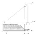
- FIG. 4 is a diagram for explaining an example of a method of measuring the temperature-time transition of the surface of the steelmaking slag in the steam treatment method of the steelmaking slag according to the present invention.
- the thermography 11 is provided on the bed of the slag treatment tank 1 in order to measure the temperature of the surface of the steelmaking slag 3. Then, the temperature transition of each section of the surface and the slope of the steelmaking slag 3 on the bed is measured by the thermal image image by the thermography 11.
- thermography 11 it is possible to measure the temperature of the surface of the steelmaking slag 3 by arranging optical fibers that can measure the temperature at each position in the length direction at close intervals.
- the optical fibers may be arranged like a mesh, but since the temperature can be measured by dividing the optical fibers in the length direction, the optical fibers may be arranged in parallel in either direction.
- the slag treatment tank 1 it is necessary to arrange the slag treatment tank 1 up to the edge of the bed.
- the interval for arranging the optical fibers is 0.5 m or less, and it is desirable to narrow the interval to about 0.2 m.
- thermography 11 when the thermography 11 is used, the digital image of the thermal image is observed a plurality of times in a certain period (several tens of seconds), and each pixel (bed) in the digital image of the thermal image in the compartment is observed.
- the maximum temperature within the period (corresponding to the coordinate points of) is calculated as the temperature of each pixel.
- the temperature distribution of each section is obtained from the maximum temperature of each pixel within a certain period.
- the steam flow rate distribution of each section on the surface of the steelmaking slag 3 can be estimated.
- the estimated steam flow rate distribution of each section is reflected in the steam amount control for each section.
- the distribution of steam flow rate in each section is estimated by measuring the temperature of each section on the surface of the steelmaking slag 3 over time. Then, by reflecting the distribution of the obtained steam flow rate in each section in the control of the steam flow rate in each section, it was found that the section where the steam injection can be reduced and the section where the steam blowing needs to be increased can be found. Steam can be rationally blown. As a result, the steelmaking slag 3 can be heated and kept warm more constantly, and steam treatment can be performed while suppressing the amount of steam used.
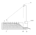
- FIG. 5 is a diagram for explaining another example of a method of measuring the temperature-time transition of the surface of the steelmaking slag in the steam treatment method of the steelmaking slag according to the present invention.
- the surface temperature of each section is measured by the thermometer 12.
- the distribution of the steam flow rate can be obtained from an earlier stage in which the temperature is raised downward in the process of raising the temperature of the steelmaking slag. Is possible. Further, it is preferable that the distribution of steam flow rate can be estimated based on the measurement data of more depths, the measurement system is increased, and more rational steam flow rate control becomes possible.
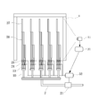
- FIG. 6 is a diagram for explaining an example of a method of controlling the amount of steam blown into each section of the steelmaking slag based on the estimated distribution of the steam flow rate in the steam treatment method of the steelmaking slag according to the present invention.
- the structure of the back surface of the bed of the slag treatment tank 1 is shown.
- the steam supply pipe 2 is provided with a main flow rate adjusting valve 21 on the upstream side thereof, and is provided with five first branch pipes 22 on the downstream side thereof.
- Each first branch pipe 22 is provided with three second branch pipes 23.
- Each second branch pipe 23 includes a flow rate adjusting valve 24 and a flow meter 25 from the upstream side, a piping portion 26 having no steam ejection hole, and a piping portion 27 having a steam ejection hole.
- the surface compartments of the steelmaking slag are examples of 15 compartments in total.
- the control of the main flow rate adjusting valve 21 and the flow rate adjusting valve 24 is carried out as follows. First, the thermography 11 captures a thermal image of each section of the surface of the steelmaking slag (not shown) stacked on the slag processing tank 1. Next, the image processing unit 31 estimates the distribution of the steam flow rate of each section from the captured thermal image, and determines the amount of steam blown into each section based on the estimated steam flow rate distribution of each section. Then, the main flow rate adjusting valve 21 and the flow rate adjusting valve 24 are controlled by the valve control unit 32 according to the determined amount of steam blown in each section, and steam is blown individually in each of the 15 sections. To do.
- the opening degree of each of the main flow rate adjusting valve 21 and the flow rate adjusting valve 24 is automatically adjusted at regular intervals, and a large amount of steam flows in a section where the steam flow rate is lower than the others, and conversely, the steam flow rate is different. Suppress steam flow in more or more compartments.
- the steam flow rate in the entire bed is suppressed by selecting a group of sections that are easy to flow. Can be reduced as compared to the case where there is no control for each part.
- the steam pipes such as the steam supply pipe 2, the first branch pipe 22, and the second branch pipe 23 are separated from the temperature measurement point. Therefore, it should be noted that there is a time lag between changing the steam flow rate and changing the measured temperature.
- the steam flow rate is controlled by the height of the distribution of the steam flow rate estimated based on the temperature measurement, it is necessary to control in consideration of the above-mentioned time difference. For example, in PID control, it is desirable to measure the steam flow rate and temperature in advance to determine each parameter.
- the particle size distribution and filling condition of the slag are not always constant, the optimum values of the parameters change for each treatment. Therefore, it is desirable to set the P time and the I time to be 1.2 to 1.5 times longer than the parameters determined from the prior measurement to prevent overshoot.
- the converter slag having a particle size range of 0 to 40 mm was steam-treated, and the lower layer roadbed material of CS-40 was produced from the steam-treated converter slag.
- the prepared converter slag was loaded at a height of 2.5 m above the bed of the slag treatment tank.
- the slope of the stacked converter slag on the slag processing tank inlet side was about 40 °.
- the surface of the converter slag was divided into 15 compartments having the same area, and the amount of steam blown into each of the 15 compartments was controlled according to the steam treatment method of the present invention to carry out steam treatment of the converter slag.
- thermometer thermocouple
Landscapes
- Engineering & Computer Science (AREA)
- Chemical & Material Sciences (AREA)
- Physics & Mathematics (AREA)
- General Physics & Mathematics (AREA)
- Spectroscopy & Molecular Physics (AREA)
- Ceramic Engineering (AREA)
- Materials Engineering (AREA)
- General Engineering & Computer Science (AREA)
- Mechanical Engineering (AREA)
- Structural Engineering (AREA)
- Organic Chemistry (AREA)
- Curing Cements, Concrete, And Artificial Stone (AREA)
- Furnace Details (AREA)
- Radiation Pyrometers (AREA)
- Waste-Gas Treatment And Other Accessory Devices For Furnaces (AREA)
Abstract
ベッド中の製鋼スラグの状態によらず合理的な蒸気流量制御が可能で、蒸気使用量を抑制した製鋼スラグの蒸気処理ができる、製鋼スラグの蒸気処理方法を提供する。製鋼スラグをベッド上に積み、蒸気をベッドの下方から吹き込んで製鋼スラグを蒸気処理する製鋼スラグの蒸気処理方法において、ベッド中の製鋼スラグの表面を一定条件の大きさの複数の区画に分割し、分割した各区画で、製鋼スラグ表面の温度時間推移を計測し、計測した温度時間推移に基づき、製鋼スラグの各区画における蒸気流量の分布を推定し、推定した蒸気流量の分布に基づき、製鋼スラグの各区画の蒸気吹込み量を制御する。
Description
本発明は、製鋼スラグを蒸気処理する蒸気処理設備の操業において、合理的な蒸気流量制御が可能な製鋼スラグの蒸気処理方法に関する。
製鋼スラグは、緻密で固く、締め固めれば大きな荷重を支持できるため、道路の路盤材として用いられる。しかし、たとえば転炉スラグをはじめとする製鋼スラグは長時間を経て膨張性を示す性質がある。そのため、路盤材として出荷する前に膨張源の反応を予め促進して大部分を反応させておくエージング処理を実施するのが通常である。
製鋼スラグは破砕して鉄鋼スラグ路盤材として加工される。製鋼スラグ中に含まれるフリーライム(f-CaO)は水分と反応して消石灰(Ca(OH)2)となり、製鋼スラグは2倍強に膨張する。未処理で用いると数年の内に路盤を破壊する恐れがあるので、製造工程の中で蒸気により水分との反応を促進する「蒸気エージング」処理を行う。膨張率の測定方法は、非特許文献1を用いることができる。
蒸気エージング処理においては、大気圧と平衡する飽和蒸気温度近傍で処理することが、多く実施されている。処理にあたっては、数100~数1000tの製鋼スラグをほぼ平らに積み上げたベッドにする。多くの場合、壁で仕切られたピットの中に製鋼スラグを積み上げる。その後、ピット中の製鋼スラグの下に配置された蒸気供給管から蒸気を吹き込んでベッド内の製鋼スラグを約100℃に昇温し、その後蒸気量を絞って100℃近傍で製鋼スラグを数日保持する。ここで、f-CaOが水分と反応して製鋼スラグの膨張性は大きく低減する。
そのような蒸気エージング処理の方法として、複数の温度計をベッド内の製鋼スラグに挿入して設け、温度計の測温結果に応じて蒸気供給管の蒸気流量を制御する方法が提案されている(特許文献1参照)。
従来の蒸気エージング処理方法では、作業工数や蒸気使用量の合理化の観点からは処理設備は大型であるほどよい。しかしながら、処理設備を大型化すると、一つのピットに様々な履歴の製鋼スラグが入ることとなり、また、製鋼スラグをベッドに積み付ける重機での作業も積込みパターンを一定に持続することが困難である。そのため、箇所ごとの粗密差を内包する製鋼スラグベッドとなる。このため、下から蒸気を吹込み昇温する際に、製鋼スラグの粗密により蒸気の偏流が起きて、いずれの部分をも一定ペースで昇温して時間の過不足なく高温で保持することが困難になる。
このとき、製鋼スラグの昇温が遅い部分に合わせて、蒸気供給管のバルブ制御によりベッド全体の蒸気吹込み時間を延長すると、多くの蒸気が既に100℃以上に保持された製鋼スラグの部分に更に吹き込むこととなり不合理である。全体の総量を増減しても相対的に流れにくい箇所は、結局他の箇所より少ない蒸気流量のまま変化していく。すなわち、昇温の済んだ大量の蒸気が必要でない部分にも余剰に流れることになる。こうして蒸気を無駄に使っているのに、蒸気が不十分なままの部分が残り、もっとも重要な膨脹の安定化がばらついたまま残ることとなる。
また、特許文献1に開示された方法のように、温度計を製鋼スラグに挿入するのは数的に限界があり、温度計間の距離を広げざるを得ず、測温されない部分が生じる。そのため、ベッドの中の製鋼スラグにおいて、どの箇所が昇温不良でばらついているのか正確に把握できない。温度が十分に上がっていない箇所が見つけられずに残ってしまうことがあり、水浸膨張比は1ベッドの中で大小ばらついてしまう。
本発明の目的は、従来技術の抱えている上述した課題を解決して、製鋼スラグを蒸気処理する蒸気処理方法において、ベッド中の製鋼スラグの状態によらず合理的な蒸気流量制御が可能で、蒸気使用量を抑制した製鋼スラグの蒸気処理ができる、製鋼スラグの蒸気処理方法を提供することにある。
前記の目的を実現するため、本発明は、ベッド内の製鋼スラグの全面を測温できれば、ベッド内の製鋼スラグ全体での蒸気流量の分布が把握でき、その蒸気流量の分布に基づき供給する蒸気量を制御することを突き止め、以下に述べる新規な製鋼スラグの蒸気処理方法を開発するに至った。
即ち、本発明は、製鋼スラグをベッド上に積み、蒸気をベッドの下方から吹き込んで製鋼スラグを蒸気処理する製鋼スラグの蒸気処理方法において、ベッド中の製鋼スラグの表面を複数の区画に分割し、分割した各区画で、製鋼スラグ表面の温度時間推移を計測し、計測した温度時間推移に基づき、製鋼スラグの各区画における蒸気流量の分布を推定し、推定した蒸気流量の分布に基づき、製鋼スラグの各区画の蒸気吹込み量を制御する、ことを特徴とする製鋼スラグの蒸気処理方法である。
なお、前記のように構成される本発明に係る製鋼スラグの蒸気処理方法においては、
(1)前記製鋼スラグ表面の各区画における温度時間推移の計測を、ベッドの上方からベッド上に積まれた製鋼スラグの上面を熱画像観測することで行うこと、
(2)前記製鋼スラグ表面の各区画における温度時間推移の計測を、製鋼スラグの表面から挿入された複数の温度計と、ベッドの上方からベッド上に積まれた製鋼スラグの上面を熱画像観測することと、の両者による計測結果に基づき行うこと、
(3)前記熱画像観測を、サーモグラフィを用いて行うこと、
(4)前記製鋼スラグ表面の区画の1辺の長さが、積まれたベッド高さの2分の1以上、2以下の長方形として、蒸気処理を行うこと、
がより好ましい解決手段となるものと考えられる。
(1)前記製鋼スラグ表面の各区画における温度時間推移の計測を、ベッドの上方からベッド上に積まれた製鋼スラグの上面を熱画像観測することで行うこと、
(2)前記製鋼スラグ表面の各区画における温度時間推移の計測を、製鋼スラグの表面から挿入された複数の温度計と、ベッドの上方からベッド上に積まれた製鋼スラグの上面を熱画像観測することと、の両者による計測結果に基づき行うこと、
(3)前記熱画像観測を、サーモグラフィを用いて行うこと、
(4)前記製鋼スラグ表面の区画の1辺の長さが、積まれたベッド高さの2分の1以上、2以下の長方形として、蒸気処理を行うこと、
がより好ましい解決手段となるものと考えられる。
本発明に係る製鋼スラグの蒸気処理方法によれば、ベッド中の製鋼スラグの表面を複数の区画に分割し、分割した各区画で経時的に区画ごとの全面の温度時間推移を計測し、温度時間推移に基づき各区画での蒸気流量の分布を推定し、推定した蒸気流量の分布を各区画の蒸気流量制御に反映させることで、より一定な昇温、保温が可能となる。その結果、1ベッドの中での温度保持が均一化され、水浸膨張比のばらつきが低減し、大きい水浸膨張比で残留する部分がなくなり、その平均値も低下する。そのため、合理的な蒸気流量制御が可能となり、蒸気使用量を抑制しての蒸気処理が可能となる。
<一般的な製鋼スラグの蒸気処理方法について>
図1(a)、(b)は、それぞれ、本発明の対象となる製鋼スラグの蒸気処理方法を説明するための斜視図および断面図である。図1(a)、(b)に示す例において、1はスラグ処理槽、2は蒸気供給管、3は蒸気処理される製鋼スラグ、である。図1(a)、(b)に示すように、本発明に係る製鋼スラグの蒸気処理方法では、製鋼スラグ3をスラグ処理槽1のベッド上に積み、蒸気供給管2を介して蒸気をベッドの下方から吹き込んで製鋼スラグ3を蒸気処理している。蒸気供給管2は、床敷と呼ばれる比較的粗粒のスラグの充填層の中に埋設されることがある。その場合は、床敷の上に製鋼スラグ3を積む。床敷を設ける目的は、蒸気供給管2の直上以外の場所の製鋼スラグ3にも蒸気が分散して吹き込まれるようにすることと、重機などによる製鋼スラグ3の積み付けと搬出の際に蒸気供給管2が破損しないようにすることである。前者の目的のためには、床敷には例えば目開き5mmの篩の篩上を用いて通気性を向上させることが望ましい。なお、スラグ処理槽1のベッド上に積まれた製鋼スラグ3の表面には、上方を向く上面と端部で徐々に厚みが薄くなる斜面とがあるが、その両者が本発明でいう製鋼スラグの表面の概念に含まれる。
図1(a)、(b)は、それぞれ、本発明の対象となる製鋼スラグの蒸気処理方法を説明するための斜視図および断面図である。図1(a)、(b)に示す例において、1はスラグ処理槽、2は蒸気供給管、3は蒸気処理される製鋼スラグ、である。図1(a)、(b)に示すように、本発明に係る製鋼スラグの蒸気処理方法では、製鋼スラグ3をスラグ処理槽1のベッド上に積み、蒸気供給管2を介して蒸気をベッドの下方から吹き込んで製鋼スラグ3を蒸気処理している。蒸気供給管2は、床敷と呼ばれる比較的粗粒のスラグの充填層の中に埋設されることがある。その場合は、床敷の上に製鋼スラグ3を積む。床敷を設ける目的は、蒸気供給管2の直上以外の場所の製鋼スラグ3にも蒸気が分散して吹き込まれるようにすることと、重機などによる製鋼スラグ3の積み付けと搬出の際に蒸気供給管2が破損しないようにすることである。前者の目的のためには、床敷には例えば目開き5mmの篩の篩上を用いて通気性を向上させることが望ましい。なお、スラグ処理槽1のベッド上に積まれた製鋼スラグ3の表面には、上方を向く上面と端部で徐々に厚みが薄くなる斜面とがあるが、その両者が本発明でいう製鋼スラグの表面の概念に含まれる。
本発明に係る製鋼スラグの蒸気処理方法は、図1(a)、(b)に示す例において、スラグ処理槽1のベッド中の製鋼スラグ3の表面を複数の区画に分割し、分割した各区画で、製鋼スラグ表面の温度時間推移を計測し、計測した温度時間推移に基づき、製鋼スラグの各区画における蒸気流量の分布を推定し、推定した蒸気流量の分布に基づき、製鋼スラグの各区画の蒸気吹込み量を制御する点に特徴がある。
<製鋼スラグ表面を複数の区画に分割する工程について>
図2は、本発明に係る製鋼スラグの蒸気処理方法において、ベッド中の製鋼スラグの表面を複数の区画に分割する方法の一例を説明するための図である。図2に示す例においては、スラグ処理槽1のベッド中の製鋼スラグ3の表面を、幅方向に同じ幅で5分割し、奥行き方向に同じ幅で3分割し、全体で15区画に分割している。本発明において、上記分割数は一例であり、他の分割数とすることもできる。
図2は、本発明に係る製鋼スラグの蒸気処理方法において、ベッド中の製鋼スラグの表面を複数の区画に分割する方法の一例を説明するための図である。図2に示す例においては、スラグ処理槽1のベッド中の製鋼スラグ3の表面を、幅方向に同じ幅で5分割し、奥行き方向に同じ幅で3分割し、全体で15区画に分割している。本発明において、上記分割数は一例であり、他の分割数とすることもできる。
図3(a)、(b)は、それぞれ、本発明に係る製鋼スラグの蒸気処理方法において、製鋼スラグの表面を複数の区画に分割する際に、矩形の1辺の長さの範囲を、製鋼スラグの積み付け高さに対する比率で決定する例を説明するための図である。ここで、図3(a)、(b)に示す例において、表面の区画の適正な大きさは、スラグ積み付けの高さ(Hとする)により異なる。各区画を矩形とした場合、1辺の長さが2分の1H未満では、幅が狭すぎ、蒸気の拡散の影響を受け、区画直下にある蒸気供給管と、隣接する蒸気供給配管のどこに問題があるか判断が困難となる場合がある。1辺の長さが2H超だと、区画が大きすぎ、区画の内部で蒸気ばらつきが生じうるため、区画全体の蒸気量制御では問題解消が困難になる場合がある。そのため、製鋼スラグ表面の区画の1辺の長さ(aまたはb)が、積まれたベッド高さの2分の1以上、2以下の長方形として、蒸気処理を行うことが好ましい。
<製鋼スラグ表面の温度時間推移を計測する工程について>
図4は、本発明に係る製鋼スラグの蒸気処理方法において、製鋼スラグ表面の温度時間推移を計測する方法の一例を説明するための図である。図4に示す例では、製鋼スラグ3の表面の温度を計測するために、サーモグラフィ11をスラグ処理槽1のベッド上に設けている。そして、ベッド上の製鋼スラグ3の表面および斜面の各区画の温度推移を、サーモグラフィ11による熱画像イメージにより測定している。
図4は、本発明に係る製鋼スラグの蒸気処理方法において、製鋼スラグ表面の温度時間推移を計測する方法の一例を説明するための図である。図4に示す例では、製鋼スラグ3の表面の温度を計測するために、サーモグラフィ11をスラグ処理槽1のベッド上に設けている。そして、ベッド上の製鋼スラグ3の表面および斜面の各区画の温度推移を、サーモグラフィ11による熱画像イメージにより測定している。
本例では、サーモグラフィ11の代わりに、1本で長さ方向の位置毎に測温が可能な光ファイバを緊密な間隔で並べて、製鋼スラグ3の表面の温度を計測することもできる。光ファイバは、網の目のように並べても良いが、長さ方向は分割して測温できるので、いずれかの方向に光ファイバを平行に並べれば良い。製鋼スラグ3の表面全面を計測するためには、スラグ処理槽1のベッドの端にまで並べる必要がある。光ファイバを並べる間隔は0.5m以下で、0.2m程度まで間隔を狭めることが望ましい。
図4に示す例のように、サーモグラフィ11を使用する場合、熱画像のデジタルイメージを一定期間(数10秒)の間に複数回観測し、区画内の熱画像のデジタルイメージにおける各画素(ベッドの座標点に相当)の期間内の最高温度を各画素の温度として求める。これにより、ベッドから立ち上がる湯気の観測干渉を回避することができ、製鋼スラグ3の表面の各区画の温度分布を正確に測定できる。このように、一定期間内の各画素の最高温度から、各区画の温度分布を求める。そして、温度分布の変化を経時的に計測することで、製鋼スラグ3の表面における各区画の蒸気流量分布を推定することができる。推定した各区画の蒸気流量分布を、区画ごとの蒸気量制御に反映させる。
本例では、製鋼スラグ3の表面の各区画の温度を経時的に計測することで、各区画の蒸気流量の分布が推算される。そして、得られた各区画の蒸気流量の分布を各区画の蒸気流量の制御に反映させることで、蒸気吹込みを減量して構わない区画と蒸気吹込みの増量が必要な区画とがわかり、合理的に蒸気を吹込むことができる。その結果、製鋼スラグ3に対し、より一定な昇温、保温が可能となり、蒸気使用量を抑制しての蒸気処理が可能となる。
図5は、本発明に係る製鋼スラグの蒸気処理方法において、製鋼スラグ表面の温度時間推移を計測する方法の他の例を説明するための図である。図5に示す例では、サーモグラフィ11による各区画の製鋼スラグの表面温度の計測に加えて、温度計12により各区画の表面温度を測温している。この例によれば、温度計12による各区画の表面温度の測定を併用することで、製鋼スラグの昇温過程で下方の昇温が行われているより早い段階から蒸気流量の分布を求めることが可能となる。また、蒸気流量の分布の推定をより多くの深度の測定データに基づき行うことができ、測定の制度を増し、より合理的な蒸気流量制御が可能となるため好ましい。
<蒸気吹込み量を制御する工程について>
図6は、本発明に係る製鋼スラグの蒸気処理方法において、推定した蒸気流量の分布に基づき、製鋼スラグの各区画の蒸気吹込み量を制御する方法の一例を説明するための図である。図6に示す例では、スラグ処理槽1のベッドの裏面の構造を示している。図6示す例において、蒸気供給管2は、その上流側に主流量調整バルブ21を備えるとともに、その下流側に5つの第1の枝管22を備えている。各第1の枝管22には、3つの第2の枝管23が設けられている。各第2の枝管23は、上流側から流量調整バルブ24と流量計25と、蒸気噴出孔のない配管部26と、蒸気噴出孔のある配管部27と、を備えている。製鋼スラグの表面の区画は、全部で15区画の例となっている。
図6は、本発明に係る製鋼スラグの蒸気処理方法において、推定した蒸気流量の分布に基づき、製鋼スラグの各区画の蒸気吹込み量を制御する方法の一例を説明するための図である。図6に示す例では、スラグ処理槽1のベッドの裏面の構造を示している。図6示す例において、蒸気供給管2は、その上流側に主流量調整バルブ21を備えるとともに、その下流側に5つの第1の枝管22を備えている。各第1の枝管22には、3つの第2の枝管23が設けられている。各第2の枝管23は、上流側から流量調整バルブ24と流量計25と、蒸気噴出孔のない配管部26と、蒸気噴出孔のある配管部27と、を備えている。製鋼スラグの表面の区画は、全部で15区画の例となっている。
主流量調整バルブ21および流量調整バルブ24の制御は、以下のようにして実施されている。まず、スラグ処理槽1上に積まれた製鋼スラグ(図示せず)の表面の各区画の熱画像イメージを、サーモグラフィ11で撮像する。次に、画像処理部31により、撮像した熱画像イメージから、各区画の蒸気流量の分布を推定するとともに、推定した各区画の蒸気流量分布に基づき各区画の蒸気吹込み量を決定する。そして、決定された各区画の蒸気吹込み量に応じて、バルブ制御部32により、主流量調整バルブ21および流量調整バルブ24を制御し、15区画のそれぞれの区画で個別に蒸気吹込みを実施する。
以上の構成により、主流量調整バルブ21および流量調整バルブ24のそれぞれの開度を一定時間ごとに自動調節して、蒸気流量が他より低い区画では蒸気を多量に流し、反対に蒸気流量が他よりも多いあるいは過剰な区画では蒸気流量を抑制する。ベッド全体での製鋼スラグの昇温速度均衡のため、単純に昇温が悪い区画の蒸気量を増やすだけでなく、流れやすい区画群を選んで蒸気流量を抑制することで、ベッド全体の蒸気流量を、部分ごとの制御のない場合に比べて低下させることができる。
蒸気供給管2、第1の枝管22、第2の枝管23などの蒸気配管と測温箇所とは離れている。そのため、蒸気流量を変化させてから測定される温度が変化するまでには時間差が生じるので、注意が必要である。測温に基づいて推定した蒸気流量の分布の高低によって蒸気流量を制御する場合には、上述した時間差を考慮した制御が必要である。例えば、PID制御においては事前に蒸気流量と温度とを測定して各パラメータを決定することが望ましい。しかし、スラグの粒径分布や充填状況は必ずしも一定でないため、パラメータの最適値は処理毎に変化する。そのため、事前の測定から決定したパラメータに対して、P時間とI時間とを1.2~1.5倍程度長く設定してオーバーシュートを防ぐことが望ましい。
図1(a)、(b)に示す蒸気処理方法に従って、粒度範囲0~40mmの転炉スラグを蒸気処理し、蒸気処理した転炉スラグからCS-40の下層路盤材を製造した。転炉スラグの蒸気処理にあたっては、準備した転炉スラグをスラグ処理槽のベッド上2.5mの高さに積んだ。積まれた転炉スラグのスラグ処理槽入口側の斜面は約40°であった。転炉スラグの表面を、同一面積の15区画に分割し、15区画の各区画に対し本発明の蒸気処理方法に従って蒸気吹込み量を制御して、転炉スラグの蒸気処理を実施した。なお、区画の大きさは図3(a)、(b)に示すa、bにつき、a=1.8H、b=1.6Hとした。
発明例1は、図3に示すように、サーモグラフィのみで転炉スラグの表面温度を測定した。発明例2は、図4に示すように、サーモグラフィに加えて温度計(熱電対)を転炉スラグ上部から1m深度に四方1.5m間隔で挿入して、サーモグラフィと温度計とにより転炉スラグの表面温度を測定した。比較例は、従来のように、上記発明例2と同様に配置した温度計のみで転炉スラグの表面温度を測定し、蒸気吹き込み量の15区画個別の調整はおこなわず、全区画合計の調整をおこなった。
発明例1、発明例2および比較例において、昇温期間は、初期0.6kg/t-スラグで開始し、全点(発明例1、2では全座標)が100℃に達するまでとした。ここで、発明例1および発明例2では、測温結果から中途で100℃に到達した区画では100℃を保つように蒸気吹き込み量を減らした。また、保温期間は、初期0.6kg/t-スラグで開始し、48時間保持とした。ここで、発明例1および発明例2では、中途で100℃に到達した区画では100℃を保つように蒸気吹き込み量を減らした。蒸気処理終了後、各区画の転炉スラグから10点の試料を採取し、水浸膨張比を非特許文献1に記載の方法に従って求めた。結果を、以下の表1に示す。

表1の結果から、発明例1および発明例2と比較例とを比較すると、昇温期間中に転炉スラグの表面での昇温状況に応じて蒸気量を変化させるため、昇温の遅れやバラツキを緩和でき、発明例1および発明例2では比較例と比較して、100℃到達時間が短縮し、蒸気原単位も低下することがわかった。また、発明例1と発明例2とを比較すると、発明例2では発明例1と比べて、昇温のさらに早い時期から蒸気量制御に入るため、昇温時間や蒸気原単位がさらに低減できることがわかった。その結果、発明例1および発明例2では比較例にくらべて、より信頼性の高い路盤材製品の製造が可能となることがわかった。
本発明の製鋼スラグの蒸気処理方法によれば、製鋼スラグだけでなく、蒸気処理を必要とするその他の塊状または粉状の粒体の処理においても、合理的な蒸気流量制御が可能で、蒸気使用量を抑制した蒸気処理ができる。
1 スラグ処理槽
2 蒸気供給管
3 製鋼スラグ
11 サーモグラフィ
12 温度計
21 主流量調整バルブ
22 第1の枝管
23 第2の枝管
24 流量調整バルブ
25 流量計
26 蒸気噴出孔のない配管部
27 蒸気噴出孔のある配管部
31 画像処理部
32 バルブ制御部
2 蒸気供給管
3 製鋼スラグ
11 サーモグラフィ
12 温度計
21 主流量調整バルブ
22 第1の枝管
23 第2の枝管
24 流量調整バルブ
25 流量計
26 蒸気噴出孔のない配管部
27 蒸気噴出孔のある配管部
31 画像処理部
32 バルブ制御部
Claims (5)
- 製鋼スラグをベッド上に積み、蒸気をベッドの下方から吹き込んで製鋼スラグを蒸気処理する製鋼スラグの蒸気処理方法において、
ベッド中の製鋼スラグの表面を複数の区画に分割し、
分割した各区画で、製鋼スラグ表面の温度時間推移を計測し、
計測した温度時間推移に基づき、製鋼スラグの各区画における蒸気流量の分布を推定し、
推定した蒸気流量の分布に基づき、製鋼スラグの各区画の蒸気吹込み量を制御する、
ことを特徴とする製鋼スラグの蒸気処理方法。 - 前記製鋼スラグ表面の各区画における温度時間推移の計測を、
ベッドの上方からベッド上に積まれた製鋼スラグの上面を熱画像観測することで行うことを特徴とする請求項1に記載の製鋼スラグの蒸気処理方法。 - 前記製鋼スラグ表面の各区画における温度時間推移の計測を、
製鋼スラグの表面から挿入された複数の温度計と、ベッドの上方からベッド上に積まれた製鋼スラグの上面を熱画像観測することと、の両者による計測結果に基づき行うことを特徴とする請求項1に記載の製鋼スラグの蒸気処理方法。 - 前記熱画像観測を、サーモグラフィを用いて行うことを特徴とする請求項2または3に記載の製鋼スラグの蒸気処理方法。
- 前記製鋼スラグ表面の区画の1辺の長さが、積まれたベッド高さの2分の1以上、2以下の長方形として、蒸気処理を行うことを特徴とする請求項1~4のいずれか1項に記載の製鋼スラグの蒸気処理方法。
Priority Applications (1)
| Application Number | Priority Date | Filing Date | Title |
|---|---|---|---|
| JP2021513603A JP7248106B2 (ja) | 2019-04-10 | 2020-04-02 | 製鋼スラグの蒸気処理方法 |
Applications Claiming Priority (2)
| Application Number | Priority Date | Filing Date | Title |
|---|---|---|---|
| JP2019074905 | 2019-04-10 | ||
| JP2019-074905 | 2019-04-10 |
Publications (1)
| Publication Number | Publication Date |
|---|---|
| WO2020209174A1 true WO2020209174A1 (ja) | 2020-10-15 |
Family
ID=72751655
Family Applications (1)
| Application Number | Title | Priority Date | Filing Date |
|---|---|---|---|
| PCT/JP2020/015197 Ceased WO2020209174A1 (ja) | 2019-04-10 | 2020-04-02 | 製鋼スラグの蒸気処理方法 |
Country Status (2)
| Country | Link |
|---|---|
| JP (1) | JP7248106B2 (ja) |
| WO (1) | WO2020209174A1 (ja) |
Cited By (2)
| Publication number | Priority date | Publication date | Assignee | Title |
|---|---|---|---|---|
| JP2024072303A (ja) * | 2022-11-16 | 2024-05-28 | Jfeスチール株式会社 | スラグの蒸気エージング方法 |
| JP2024088480A (ja) * | 2022-12-20 | 2024-07-02 | Jfeスチール株式会社 | 通気処理設備、及び、通気処理設備の設計方法 |
Citations (4)
| Publication number | Priority date | Publication date | Assignee | Title |
|---|---|---|---|---|
| JPH04175250A (ja) * | 1990-11-06 | 1992-06-23 | Sumitomo Metal Ind Ltd | 製鋼スラグのエージング処理方法およびその装置 |
| JPH05311213A (ja) * | 1992-05-08 | 1993-11-22 | Nkk Corp | 水砕スラグの製造方法 |
| JPH07196343A (ja) * | 1993-12-29 | 1995-08-01 | Nippon Steel Corp | 製鋼スラグのエージング方法 |
| JP2017081814A (ja) * | 2015-10-29 | 2017-05-18 | Jfeスチール株式会社 | スラグ材の製造方法 |
Family Cites Families (2)
| Publication number | Priority date | Publication date | Assignee | Title |
|---|---|---|---|---|
| US5463222A (en) * | 1994-01-24 | 1995-10-31 | Colorado Seminary | Thermal imaging system for internal combustion engines |
| JP2012057369A (ja) | 2010-09-09 | 2012-03-22 | Yokogawa Bridge Corp | 熱画像を利用したコンクリートの施工方法 |
-
2020
- 2020-04-02 WO PCT/JP2020/015197 patent/WO2020209174A1/ja not_active Ceased
- 2020-04-02 JP JP2021513603A patent/JP7248106B2/ja active Active
Patent Citations (4)
| Publication number | Priority date | Publication date | Assignee | Title |
|---|---|---|---|---|
| JPH04175250A (ja) * | 1990-11-06 | 1992-06-23 | Sumitomo Metal Ind Ltd | 製鋼スラグのエージング処理方法およびその装置 |
| JPH05311213A (ja) * | 1992-05-08 | 1993-11-22 | Nkk Corp | 水砕スラグの製造方法 |
| JPH07196343A (ja) * | 1993-12-29 | 1995-08-01 | Nippon Steel Corp | 製鋼スラグのエージング方法 |
| JP2017081814A (ja) * | 2015-10-29 | 2017-05-18 | Jfeスチール株式会社 | スラグ材の製造方法 |
Cited By (4)
| Publication number | Priority date | Publication date | Assignee | Title |
|---|---|---|---|---|
| JP2024072303A (ja) * | 2022-11-16 | 2024-05-28 | Jfeスチール株式会社 | スラグの蒸気エージング方法 |
| JP7722338B2 (ja) | 2022-11-16 | 2025-08-13 | Jfeスチール株式会社 | スラグの蒸気エージング方法 |
| JP2024088480A (ja) * | 2022-12-20 | 2024-07-02 | Jfeスチール株式会社 | 通気処理設備、及び、通気処理設備の設計方法 |
| JP7754078B2 (ja) | 2022-12-20 | 2025-10-15 | Jfeスチール株式会社 | 通気処理設備、及び、通気処理設備の設計方法 |
Also Published As
| Publication number | Publication date |
|---|---|
| JPWO2020209174A1 (ja) | 2020-10-15 |
| JP7248106B2 (ja) | 2023-03-29 |
Similar Documents
| Publication | Publication Date | Title |
|---|---|---|
| Nassar et al. | Intra-layer closed-loop control of build plan during directed energy additive manufacturing of Ti–6Al–4V | |
| Kapoor et al. | Softening of Al during multi-axial forging in a channel die | |
| JP7248106B2 (ja) | 製鋼スラグの蒸気処理方法 | |
| KR101376565B1 (ko) | 연속 소둔라인 급냉대의 스트립 온도제어 방법 및 장치 | |
| EP1987291B1 (en) | Control of a system with a large thermal capacity | |
| JP2006113724A (ja) | 制御方法、温度制御方法、温度調節器、熱処理装置、プログラムおよび記録媒体 | |
| Ding et al. | A design of crucible susceptor for the seeds preservation during a seeded directional solidification process | |
| JP2016156612A (ja) | 熱処理炉及び熱処理方法 | |
| JP5862872B2 (ja) | 焼結機および気体燃料供給方法 | |
| Burns et al. | Two dimensional phase field crystal study of thermo-density coupling: Thermal expansion, recalescence, and plasticity | |
| US20190144961A1 (en) | Real-time control of the heating of a part by a steel furnace or heat treatment furnace | |
| CN108407063B (zh) | 一种隔墙板蒸汽养护方法及混凝土制品的蒸汽养护方法 | |
| CN109136491B (zh) | 一种含铌钢加热工艺动态控制方法 | |
| TWI853478B (zh) | 高爐之熔鐵溫度預測方法、高爐之熔鐵溫度預測模型之學習方法、高爐之操作方法、高爐之熔鐵溫度預測裝置、熔鐵溫度預測系統以及終端裝置 | |
| JP7337769B2 (ja) | 蒸気エージング方法 | |
| KR101108285B1 (ko) | 가변 압력하에서의 소결밀도 실시간 모니터링 방법 | |
| CN115786692A (zh) | 基于在线过程模拟的球团焙烧温度控制方法 | |
| Bott et al. | Theoretical and experimental analysis of selective oxide and nitride formation in Fe–Al alloys | |
| JP7252523B2 (ja) | 製鋼スラグの蒸気処理操業方法 | |
| Roy et al. | An exclusion distance controls the efflorescence pattern distribution on porous media during salt solution evaporation | |
| JP7722338B2 (ja) | スラグの蒸気エージング方法 | |
| Dmitriev et al. | The estimation of the thermal properties of refractory materials according to the temperatures acceleration curve at the blast furnace blowing-in | |
| EP1984156A1 (en) | A process for manufacturing ceramic tiles | |
| JP2003293030A (ja) | 鋼板の冷却方法 | |
| JP2009228071A (ja) | 焼結層内のヒートパターン測定方法 |
Legal Events
| Date | Code | Title | Description |
|---|---|---|---|
| 121 | Ep: the epo has been informed by wipo that ep was designated in this application |
Ref document number: 20787372 Country of ref document: EP Kind code of ref document: A1 |
|
| ENP | Entry into the national phase |
Ref document number: 2021513603 Country of ref document: JP Kind code of ref document: A |
|
| NENP | Non-entry into the national phase |
Ref country code: DE |
|
| 122 | Ep: pct application non-entry in european phase |
Ref document number: 20787372 Country of ref document: EP Kind code of ref document: A1 |