WO2020209103A1 - Dispositif et procédé de traitement d'informations, dispositif et procédé de reproduction, et programme - Google Patents
Dispositif et procédé de traitement d'informations, dispositif et procédé de reproduction, et programme Download PDFInfo
- Publication number
- WO2020209103A1 WO2020209103A1 PCT/JP2020/014120 JP2020014120W WO2020209103A1 WO 2020209103 A1 WO2020209103 A1 WO 2020209103A1 JP 2020014120 W JP2020014120 W JP 2020014120W WO 2020209103 A1 WO2020209103 A1 WO 2020209103A1
- Authority
- WO
- WIPO (PCT)
- Prior art keywords
- gain
- value
- correction value
- gain correction
- listener
- Prior art date
Links
Images


Classifications
-
- H—ELECTRICITY
- H04—ELECTRIC COMMUNICATION TECHNIQUE
- H04R—LOUDSPEAKERS, MICROPHONES, GRAMOPHONE PICK-UPS OR LIKE ACOUSTIC ELECTROMECHANICAL TRANSDUCERS; DEAF-AID SETS; PUBLIC ADDRESS SYSTEMS
- H04R3/00—Circuits for transducers, loudspeakers or microphones
-
- H—ELECTRICITY
- H04—ELECTRIC COMMUNICATION TECHNIQUE
- H04S—STEREOPHONIC SYSTEMS
- H04S7/00—Indicating arrangements; Control arrangements, e.g. balance control
- H04S7/30—Control circuits for electronic adaptation of the sound field
- H04S7/302—Electronic adaptation of stereophonic sound system to listener position or orientation
- H04S7/303—Tracking of listener position or orientation
-
- H—ELECTRICITY
- H04—ELECTRIC COMMUNICATION TECHNIQUE
- H04S—STEREOPHONIC SYSTEMS
- H04S3/00—Systems employing more than two channels, e.g. quadraphonic
- H04S3/008—Systems employing more than two channels, e.g. quadraphonic in which the audio signals are in digital form, i.e. employing more than two discrete digital channels
-
- H—ELECTRICITY
- H04—ELECTRIC COMMUNICATION TECHNIQUE
- H04S—STEREOPHONIC SYSTEMS
- H04S5/00—Pseudo-stereo systems, e.g. in which additional channel signals are derived from monophonic signals by means of phase shifting, time delay or reverberation
-
- H—ELECTRICITY
- H04—ELECTRIC COMMUNICATION TECHNIQUE
- H04S—STEREOPHONIC SYSTEMS
- H04S7/00—Indicating arrangements; Control arrangements, e.g. balance control
-
- H—ELECTRICITY
- H04—ELECTRIC COMMUNICATION TECHNIQUE
- H04S—STEREOPHONIC SYSTEMS
- H04S2400/00—Details of stereophonic systems covered by H04S but not provided for in its groups
- H04S2400/01—Multi-channel, i.e. more than two input channels, sound reproduction with two speakers wherein the multi-channel information is substantially preserved
-
- H—ELECTRICITY
- H04—ELECTRIC COMMUNICATION TECHNIQUE
- H04S—STEREOPHONIC SYSTEMS
- H04S2400/00—Details of stereophonic systems covered by H04S but not provided for in its groups
- H04S2400/11—Positioning of individual sound objects, e.g. moving airplane, within a sound field
-
- H—ELECTRICITY
- H04—ELECTRIC COMMUNICATION TECHNIQUE
- H04S—STEREOPHONIC SYSTEMS
- H04S2400/00—Details of stereophonic systems covered by H04S but not provided for in its groups
- H04S2400/13—Aspects of volume control, not necessarily automatic, in stereophonic sound systems
Definitions
- the present technology relates to information processing devices and methods, playback devices and methods, and programs, and more particularly to information processing devices and methods, playback devices and methods, and programs that enable easier gain correction.
- Non-Patent Document 1 the MPEG (Moving Picture Experts Group) -H3D Audio standard is known (see, for example, Non-Patent Document 1 and Non-Patent Document 2).
- 3D Audio which is handled by the MPEG-H 3D Audio standard, etc., it is possible to reproduce the direction, distance, and spread of three-dimensional sound, making it possible to reproduce audio with a more realistic feeling than conventional stereo playback. Become.
- the number of dimensions of the position information of the object is higher than that of stereo (3D Audio is 3D and stereo is 2D). Therefore, in 3D Audio, the time cost is high especially in the work of determining the parameters that compose the metadata for each object such as the horizontal angle and vertical angle indicating the position of the object, the distance, and the gain about the object. ..
- gain correction can be performed more easily so that 3D Audio content of sufficient quality can be produced in a short time.
- This technology was made in view of such a situation, and makes it easier to perform gain correction.
- the information processing device of the first aspect of the present technology determines a gain correction value for determining a gain value correction value for gain-correcting the audio signal of the audio object according to the direction of the audio object as seen by the listener. It has a part.
- the information processing method or program of the first aspect of the present technology steps to determine a gain value correction value for gain-correcting the audio signal of the audio object according to the direction of the audio object as seen by the listener. Including.
- a gain value correction value for gain-correcting the audio signal of the audio object is determined according to the direction of the audio object as seen by the listener.
- the playback device of the second aspect of the present technology is a correction value of a gain value for gain-correcting the audio signal of the audio object based on the position information indicating the position of the audio object, and is a correction value of the gain value seen from the listener.
- a gain correction unit that determines a correction value according to the direction of the audio object and corrects the gain of the audio signal based on the gain value corrected by the correction value, and the audio obtained by the gain correction. It includes a renderer processing unit that performs rendering processing based on the signal and generates reproduction signals of a plurality of channels for reproducing the sound of the audio object.
- the reproduction method or program of the second aspect of the present technology is a correction value of a gain value for gain-correcting the audio signal of the audio object based on the position information indicating the position of the audio object, and is a correction value of the gain value from the listener.
- a correction value according to the direction of the viewed audio object is determined, the gain correction of the audio signal is performed based on the gain value corrected by the correction value, and the audio signal obtained by the gain correction is obtained.
- a rendering process is performed, and a step of generating playback signals of a plurality of channels for reproducing the sound of the audio object is included.
- it is a correction value of a gain value for gain-correcting the audio signal of the audio object based on the position information indicating the position of the audio object, and the audio as seen by the listener.
- a correction value according to the direction of the object is determined, the gain correction of the audio signal is performed based on the gain value corrected by the correction value, and rendering is performed based on the audio signal obtained by the gain correction.
- Processing is performed to generate playback signals of a plurality of channels for reproducing the sound of the audio object.
- the present technology makes it easier to perform gain correction by determining the gain correction value according to the orientation of the object as seen by the listener, which makes it easier, that is, sufficiently high in a short time. It enables you to produce quality 3D Audio content.
- this technology has the following features (F1) to (F5).
- Feature (F1) Determines the gain correction value of the object according to the three-dimensional auditory characteristic with respect to the localization position of the sound image.
- Feature (F2) Gain correction value for the localization position without data when the auditory characteristic is given by a table or the like. Is calculated by interpolation processing based on the gain correction value of the adjacent position.
- Feature (F3) Gain information is determined from separately determined position information in automatic mixing.
- FIG. 1 shows that when the same pink noise is reproduced from different directions, the audible loudness is the same, based on the audible loudness when a certain pink noise is reproduced directly in front of the listener. The amount of gain correction when the pink noise gain is corrected is shown. In other words, FIG. 1 shows a person's horizontal auditory characteristics.
- the vertical axis represents the gain correction amount
- the horizontal axis represents the Azimuth value (horizontal angle), which is a horizontal angle indicating the sound source position as seen by the listener.
- the Azimuth value which indicates the direction directly in front of the listener
- the Azimuth value which indicates the direction directly beside the listener, that is, the side
- ⁇ 90 degrees which is behind the listener, that is, directly behind the listener.
- the Azimuth value indicating the direction of is 180 degrees.
- the left direction when viewed from the listener is the positive direction of the Azimuth value.
- the vertical position during reproduction of pink noise is the same height as the listener. That is, assuming that the vertical angle indicating the position of the sound source in the vertical direction (elevation angle direction) as seen from the listener is the Elevation value, FIG. 1 shows an example in which the Elevation value is 0 degrees. The upward direction from the listener's point of view is the positive direction of the Elevation value.
- the average value of the gain correction amount for each Azimuth value obtained from the results of experiments conducted on multiple listeners is shown.
- the range represented by the dotted line in each Azimuth value is 95. It shows the confidence interval of%.
- the object sound source when the localization position of the object sound source is on the side of the listener, the gain of the sound of the object sound source is slightly lowered, and when the localization position of the object sound source is behind the listener, the object sound source Increasing the sound gain a little can make the listener feel as if they are hearing the same loudness.
- the vertical axis represents the gain correction amount
- the horizontal axis represents the Azimuth value (horizontal angle) indicating the sound source position as seen by the listener.
- the range represented by the dotted line in each Azimuth value shows a 95% confidence interval.
- FIG. 2 shows the gain correction amount at each Azimuth value when the Elevation value is 30 degrees.
- FIG. 3 shows the gain correction amount at each Azimuth value when the Elevation value is -30 degrees.
- the gain correction amount for the object sound source is determined based on the position information indicating the position of the object sound source and the auditory characteristics of the listener from the auditory characteristics with respect to the arrival direction of the sound as described above, it is easier to obtain an appropriate gain. It can be seen that the correction can be made.
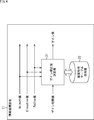
- FIG. 4 is a diagram showing a configuration example of an embodiment of an information processing device to which the present technology is applied.
- the information processing device 11 shown in FIG. 4 serves as a gain determining device for determining a gain value for gain correction of an audio signal for reproducing the sound of an audio object (hereinafter, simply referred to as an object) constituting the 3D Audio content. Function.
- Such an information processing device 11 is provided in, for example, an editing device that mixes audio signals constituting 3D Audio content.
- the information processing device 11 has a gain correction value determining unit 21 and an auditory characteristic table holding unit 22.
- Position information and initial gain values are supplied to the gain correction value determination unit 21 as metadata of objects constituting the 3D Audio content.
- the position information of the object is information indicating the position of the object as seen from the reference position in the three-dimensional space, and here the position information consists of the Azimuth value, the Elevation value, and the Radius value.
- the position of the listener is the reference position.
- the Azimuth value and the Elevation value are angles indicating the horizontal and vertical positions of the object as seen by the listener (user) at the reference position, and these Azimuth values and the Elevation values are the cases in FIGS. 1 to 3. Is similar to.
- the Radius value is the distance (radius) from the listener at the reference position in the three-dimensional space to the object.
- the position information consisting of the Azimuth value, the Elevation value, and the Radius value indicates the localization position of the sound image of the sound of the object.
- the initial gain value included in the metadata supplied to the gain correction value determining unit 21 is a gain value for gain correction of the audio signal of the object, that is, an initial value of gain information, and this gain initial value is For example, it is determined by the creator of 3D Audio content.
- the initial gain value is assumed to be 1.0.
- the gain correction value determination unit 21 corrects the gain correction amount for correcting the initial gain value of the object based on the position information as the supplied metadata and the auditory characteristic table held in the auditory characteristic table holding unit 22. Determine the gain correction value to be shown.
- the gain correction value determining unit 21 corrects the supplied initial gain value based on the determined gain correction value, and the gain value obtained as a result is finally used to gain-correct the audio signal of the object.
- the information indicates the amount of gain correction.
- the gain correction value determining unit 21 determines the gain value of the audio signal by determining the gain correction value according to the direction of the object (sound arrival direction) as seen by the listener, which is indicated by the position information. To do.
- the gain value determined in this way and the supplied position information are output to the subsequent stage as the final metadata of the object.
- the auditory characteristic table holding unit 22 holds the auditory characteristic table, and supplies the gain correction value indicated by the auditory characteristic table to the gain correction value determining unit 21 as needed.
- the auditory characteristic table is a table in which the direction of arrival of sound from the object that is the sound source to the listener, that is, the direction of the sound source as seen by the listener, and the gain correction value according to the direction are associated with each other. is there.
- the auditory characteristic table is a table in which the relative positional relationship between the sound source and the listener and the gain correction value according to the positional relationship are associated with each other.
- the gain correction value shown by the auditory characteristic table is determined according to the auditory characteristics of a person with respect to the arrival direction of the sound as shown in FIGS. 1 to 3, and is particularly audible regardless of the arrival direction of the sound.
- the gain correction amount is such that the loudness of the upper sound is constant.
- the audio signal of the object is gain-corrected using the gain value obtained by correcting the initial gain value with the gain correction value indicated by the auditory characteristic table, the sound of the same object is the same regardless of the position of the object. You will be able to hear it in size.
- FIG. 5 shows an example of an auditory characteristic table.
- the gain correction value is associated with the position of the object determined by the Azimuth value, the Elevation value, and the Radius value, that is, the direction of the object.
- Elevation and Radius values are 0 and 1.0, the vertical position of the object is at the same height as the listener, and the distance from the listener to the object is always constant. Is supposed to be.
- the object that is the sound source when the object that is the sound source is behind the listener, for example, when the Azimuth value is 180 degrees, the object is the listener, such as when the Azimuth value is 0 degrees or 30 degrees.
- the gain correction value is larger than when it is in front.
- the gain correction value is smaller than when the object is in front of the listener. There is.
- the gain correction value corresponding to the position of the object is -0.52 dB from FIG.
- the gain correction value determining unit 21 calculates the following equation (1) based on the gain correction value “-0.52 dB” read from the auditory characteristic table and the gain initial value “1.0”, and gain value “0.94”. To get.
- the gain correction value corresponding to the position of the object is 0.51 dB from FIG. Become.
- the gain correction value determining unit 21 calculates the following equation (2) based on the gain correction value “0.51 dB” read from the auditory characteristic table and the gain initial value “1.0”, and gain value “1.06”. To get.
- FIG. 5 has described an example of using a gain correction value determined based on a two-dimensional auditory characteristic in which only the horizontal direction is considered. That is, an example of using an auditory characteristic table (hereinafter, also referred to as a two-dimensional auditory characteristic table) generated based on two-dimensional auditory characteristics has been described.
- an auditory characteristic table hereinafter, also referred to as a two-dimensional auditory characteristic table
- the initial gain value may be corrected by using the gain correction value determined based on the three-dimensional auditory characteristics in consideration of not only the horizontal direction but also the vertical direction characteristics.
- the auditory characteristic table shown in FIG. 6 can be used.
- the gain correction value is associated with the position of the object determined by the Azimuth value, the Elevation value, and the Radius value, that is, the direction of the object.
- the Radius value is 1.0 for all combinations of Azimuth and Elevation values.
- the auditory characteristic table generated based on the three-dimensional auditory characteristics with respect to the arrival direction of the sound will be referred to as a particularly three-dimensional auditory characteristic table.
- the gain correction value corresponding to the position of the object is -0.07 dB from FIG.
- the gain correction value determining unit 21 calculates the following equation (3) based on the gain correction value “-0.07 dB” read from the auditory characteristic table and the gain initial value “1.0”, and gain value “0.99”. To get.
- a gain correction value based on auditory characteristics determined with respect to the position (direction) of the object was prepared in advance. That is, an example in which the gain correction value corresponding to the position information of the object is stored in the auditory characteristic table has been described.
- the position of the object is not always the position where the corresponding gain correction value is stored in the auditory characteristic table.
- the auditory characteristic table holding unit 22 holds the auditory characteristic table shown in FIG. 6, and the Azimuth value, the Elevation value, and the Radius value as position information are -120 degrees, 15 degrees, and 1.0. Suppose it is m.
- the gain correction value corresponding to the Azimuth value "-120", the Elevation value "15”, and the Radius value "1.0" is not stored in the auditory characteristic table of FIG.
- the data of a plurality of positions adjacent to the position indicated by the position information and having the corresponding gain correction value may be used so that the gain correction value determining unit 21 calculates the gain correction value at a desired position by interpolation processing or the like.
- the gain correction value corresponding to the direction (position) of the object as seen by the listener is not stored in the auditory characteristic table, the gain correction value is used in the other direction of the object as seen by the listener. It may be obtained by interpolation processing or the like based on the gain correction value corresponding to.
- VBAP Vector Base Amplitude Panning
- VBAP is for obtaining the gain values of multiple speakers in the playback environment from the metadata of the object for each object.
- the gain correction value at a desired position can be calculated by replacing the plurality of speakers in the playback environment with a plurality of gain correction values.
- the mesh is divided at a plurality of positions where gain correction values are prepared in the three-dimensional space. That is, for example, assuming that gain correction values for each of the three positions in the three-dimensional space are prepared, one triangular region having those three positions as vertices is regarded as one mesh.
- the desired position for obtaining the gain correction value is set as the attention position, and the mesh including the attention position is specified.
- a coefficient to be multiplied by the position vector indicating each of the three vertex positions when the position vector indicating the position of interest is obtained by multiplying and adding the position vectors indicating the three vertex positions constituting the specified mesh is obtained.
- each of the three coefficients thus obtained is multiplied by each of the gain correction values of the three vertex positions of the mesh including the attention position, and the sum of the gain correction values obtained by multiplying the coefficients is noticeable. It is calculated as the gain correction value of the position.
- the position vectors indicating the positions of the three vertices of the mesh including the position of interest are P 1 to P 3
- the gain correction values of the respective vertex positions are G 1 to G 3 .
- the position vector indicating the position of interest is represented by g 1 P 1 + g 2 P 2 + g 3 P 3 .
- the gain correction value of the attention position is g 1 G 1 + g 2 G 2 + g 3 G 3 .
- the gain correction value interpolation method is not limited to VBAP interpolation, and may be any other method.
- the gain correction value at the position closest to the attention position may be used as the gain correction value at the attention position.
- the gain correction value may be obtained by the linear value.
- the gain correction value at an arbitrary position can be obtained by the same calculation as in the case of the decibel value described above.
- this technology can also be applied to determine the position information as metadata of an object, that is, the Azimuth value, Elevation value, and Radius value, based on the type and priority of the object, sound pressure, pitch, etc. Is.
- the gain correction value is determined based on the position information determined based on the type and priority of the object and the three-dimensional auditory characteristic table prepared in advance.
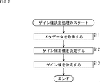
- step S11 the gain correction value determination unit 21 acquires metadata from the outside.
- the gain correction value determination unit 21 acquires the position information consisting of the Azimuth value, the Elevation value, and the Radius value and the initial gain value as metadata.
- step S12 the gain correction value determining unit 21 determines the gain correction value based on the position information acquired in step S11 and the auditory characteristic table held in the auditory characteristic table holding unit 22.
- the gain correction value determining unit 21 reads the gain correction value associated with the Azimuth value, the Elevation value, and the Radius value constituting the acquired position information from the auditory characteristic table, and determines the read gain correction value.
- the gain correction value is used.
- step S13 the gain correction value determining unit 21 determines the gain value based on the gain initial value acquired in step S11 and the gain correction value determined in step S12.
- the gain correction value determining unit 21 obtains the gain value by performing the same calculation as in the equation (1) based on the gain initial value and the gain correction value and correcting the gain initial value with the gain correction value.
- the gain correction value determining unit 21 outputs the determined gain value to the subsequent stage, and the gain value determining process ends.
- the output gain value is used for gain correction (gain adjustment) of the audio signal in the subsequent stage.
- the information processing apparatus 11 determines the gain correction value using the auditory characteristic table, and determines the gain value by correcting the initial gain value based on the gain correction value.
- gain correction can be performed more easily. This makes it possible, for example, to produce sufficiently high quality 3D Audio content more easily, that is, in a short time.
- this technology can be applied to a 3D audio content creation tool that determines the position of an object, etc., either by user input or automatically.
- the user interface (display screen) shown in FIG. 8 is used to set or adjust a gain correction value (gain value) based on the auditory characteristics with respect to the direction of the object as seen by the listener. Can be done.
- a gain correction value gain value
- the display screen of the 3D audio content creation tool is provided with a pull-down box BX11 for selecting a desired auditory characteristic from a plurality of preset auditory characteristics that are different from each other.
- a plurality of two-dimensional auditory characteristics such as male auditory characteristics, female auditory characteristics, and individual user auditory characteristics are prepared in advance, and the user operates the pull-down box BX11 to obtain desired auditory characteristics. You can choose the characteristics.
- the gain correction value at each Azimuth value according to the auditory characteristic selected by the user is displayed in the gain correction value display area R11 provided below the pull-down box BX11 in the figure. Is displayed.
- the vertical axis shows the gain correction value
- the horizontal axis shows the Azimuth value
- the curve L11 shows a negative value of the Azimuth value, that is, the gain correction value at each Azimuth value in the right direction when viewed from the listener, and the curve L12 shows the gain correction value in each Azimuth value in the left direction when viewed from the listener.
- the gain correction value is shown.
- a slider display area R12 in which a slider or the like for adjusting the gain correction value displayed in the gain correction value display area R11 is displayed is provided on the lower side. ..
- a number indicating the Azimuth value, a scale indicating the gain correction value, and a slider for adjusting the gain correction value are displayed. ..
- the slider SD11 is for adjusting the gain correction value when the Azimuth value is 30 degrees, and the user can specify a desired value as the adjusted gain correction value by moving the slider SD11 up and down. it can.
- the display of the gain correction value display area R11 is updated according to the adjustment. That is, here, the curve L12 changes according to the operation on the slider SD11.
- the gain correction value according to the desired auditory characteristic that is, the auditory characteristic table
- the gain correction value according to the selected auditory characteristic can be further adjusted.
- the user can adjust the gain correction value so as to match the individual auditory characteristics of the user by operating the slider.
- the gain correction value is adjusted by operating the slider, it is possible to make adjustments according to the user's intention, such as making a large gain correction to emphasize the object behind.
- the gain correction value in each Azimuth value is set and adjusted in this way, for example, when a save button (not shown) is operated, the gain correction value displayed in the gain correction value display area R11 and each Azimuth value are changed.
- the associated two-dimensional auditory characteristic table is generated.
- FIG. 8 has described an example in which the gain correction value is different in each direction on the right side and the left side as seen from the listener, that is, an example in which the gain correction value is asymmetrical.
- the gain correction value may be symmetrical.
- the gain correction value is set or adjusted as shown in FIG.
- the parts corresponding to those in FIG. 8 are designated by the same reference numerals, and the description thereof will be omitted as appropriate.
- FIG. 9 shows a display screen of a 3D audio content creation tool.
- a pull-down box BX11, a gain correction value display area R21, and a slider display area R22 are displayed on the display screen.
- the gain correction value at each Azimuth value is displayed as in the gain correction value display area R11 in FIG. 8, but since the gain correction values in the left and right directions are common here. , Only one curve showing the gain correction value is displayed.
- the average value of the gain correction values in each of the left and right directions can be set as the gain correction value common to the left and right.
- the average value of each gain correction value having an Azimuth value of 90 degrees and ⁇ 90 degrees in the example of FIG. 8 is a common gain correction value having an Azimuth value of ⁇ 90 degrees in the example of FIG.
- a slider or the like for adjusting the gain correction value displayed in the gain correction value display area R21 is displayed.
- the user can adjust the common gain correction value with an Azimuth value of ⁇ 30 degrees by moving the slider SD21 up and down.
- the gain correction value at each Azimuth value may be adjusted for each Elevation value.
- the same reference numerals are given to the portions corresponding to those in FIG. 8, and the description thereof will be omitted as appropriate.
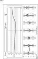
- FIG. 10 shows a display screen of a 3D audio content creation tool.
- the display screen includes a pull-down box BX11, a gain correction value display area R31 to a gain correction value display area R33, and a slider display area R34 to a slider display.
- Area R36 is displayed.
- the gain correction value is symmetrical as in the example shown in FIG. 10.
- the gain correction value at each Azimuth value when the Elevation value is 30 degrees is displayed, and the user can operate the slider etc. displayed in the slider display area R34.
- the gain correction values can be adjusted.
- the gain correction value for each Azimuth value when the Elevation value is 0 degrees is displayed in the gain correction value display area R32, and the user operates the slider or the like displayed in the slider display area R35. Therefore, those gain correction values can be adjusted.
- the gain correction value display area R33 the gain correction value at each Azimuth value when the Elevation value is -30 degrees is displayed, and the user operates the slider or the like displayed in the slider display area R36. Therefore, those gain correction values can be adjusted.
- the gain correction value for each Azimuth value is set and adjusted.
- a save button (not shown) is operated, a three-dimensional auditory characteristic table in which the gain correction value is associated with the Elevation value and the Azimuth value Is generated.
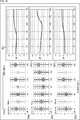
- a radar chart type gain correction value display area may be provided as shown in FIG. In FIG. 11, the parts corresponding to those in FIG. 10 are designated by the same reference numerals, and the description thereof will be omitted as appropriate.
- the pull-down box BX11, the gain correction value display area R41 to the gain correction value display area R43, and the slider display area R34 to the slider display area R36 are displayed on the display screen.
- the gain correction value is symmetrical as in the example shown in FIG.
- the gain correction value at each Azimuth value when the Elevation value is 30 degrees is displayed, and the user can operate the slider or the like displayed in the slider display area R34.
- the gain correction values can be adjusted.
- each item of the radar chart is an Azimuth value, so that the user can use not only the gain correction value in each direction (Azimuth value) and those directions but also the gain correction value between each direction. The relative difference between the two can be grasped instantly.
- the gain correction value at each Azimuth value when the Elevation value is 0 degrees is displayed in the gain correction value display area R42. Further, in the gain correction value display area R43, the gain correction value at each Azimuth value when the Elevation value is -30 degrees is displayed.
- Such an information processing device is configured as shown in FIG. 12, for example.
- the information processing device 51 shown in FIG. 12 realizes a content production tool, and displays the display screen of the content production tool on the display device 52.
- the information processing device 51 has an input unit 61, an auditory characteristic table generation unit 62, an auditory characteristic table holding unit 63, and a display control unit 64.
- the input unit 61 is composed of, for example, a mouse, a keyboard, switches, buttons, a touch panel, etc., and supplies an input signal according to the user's operation to the auditory characteristic table generation unit 62.
- the auditory characteristic table generation unit 62 generates a new auditory characteristic table based on the input signal supplied from the input unit 61 and the preset auditory characteristic table held in the auditory characteristic table holding unit 63. , Supply to the auditory characteristic table holding unit 63.
- the auditory characteristic table generation unit 62 instructs the display control unit 64 to update the display of the display screen on the display device 52 as appropriate when the auditory characteristic table is generated.
- the auditory characteristic table holding unit 63 holds a preset auditory characteristic table of auditory characteristics, and supplies the auditory characteristic table to the auditory characteristic table generation unit 62 and supplies the auditory characteristic table from the auditory characteristic table generation unit 62 as appropriate. Hold the auditory characteristics table.
- the display control unit 64 controls the display of the display screen by the display device 52 according to the instruction of the auditory characteristic table generation unit 62.
- the input unit 61, the auditory characteristic table generation unit 62, and the display control unit 64 shown in FIG. 12 may be provided in the information processing device 11 shown in FIG.
- step S41 the display control unit 64 causes the display device 52 to display the display screen of the content creation tool in response to the instruction of the auditory characteristic table generation unit 62.
- the display control unit 64 causes the display device 52 to display the display screens shown in FIGS. 8, 9, 10, 11, and the like.
- the auditory characteristic table generation unit 62 is selected by the user according to the input signal supplied from the input unit 61.
- the auditory characteristic table corresponding to the auditory characteristic is read from the auditory characteristic table holding unit 63.
- the auditory characteristic table generation unit 62 instructs the display control unit 64 to display the gain correction value display area so that the gain correction value of each Azimuth value indicated by the read auditory characteristic table is displayed on the display device 52. ..
- the display control unit 64 displays the gain correction value display area on the display screen of the display device 52 in response to the instruction of the auditory characteristic table generation unit 62.
- the user When the display screen of the content creation tool is displayed on the display device 52, the user appropriately operates the input unit 61 to change (adjust) the gain correction value by operating the slider or the like displayed in the slider display area. ) Is instructed.
- step S42 the auditory characteristic table generation unit 62 generates the auditory characteristic table according to the input signal supplied from the input unit 61.
- the auditory characteristic table generation unit 62 generates a new auditory characteristic table by changing the auditory characteristic table read from the auditory characteristic table holding unit 63 according to the input signal supplied from the input unit 61. That is, the preset auditory characteristic table is changed (updated) according to the operation of the slider or the like displayed in the slider display area.
- the auditory characteristic table generation unit 62 uses the new auditory characteristic table.
- the display control unit 64 is instructed to update the display of the gain correction value display area according to the above.
- step S43 the display control unit 64 controls the display device 52 according to the instruction of the auditory characteristic table generation unit 62, and displays according to the newly generated auditory characteristic table.
- the display control unit 64 updates the display of the gain correction value display area on the display screen of the display device 52 according to the newly generated auditory characteristic table.
- step S44 the auditory characteristic table generation unit 62 determines whether or not to end the process based on the input signal supplied from the input unit 61.
- the auditory characteristic table generation unit 62 is a signal to instruct the user to save the auditory characteristic table as an input signal by operating the input unit 61 and operating the save button or the like displayed on the display device 52. Is supplied, it is determined that the processing is completed.
- step S44 If it is determined in step S44 that the process has not yet been completed, the process returns to step S42, and the above-described process is repeated.
- step S44 determines whether the process is completed. If it is determined in step S44 that the process is completed, the process proceeds to step S45.
- step S45 the auditory characteristic table generation unit 62 supplies and holds the auditory characteristic table obtained in the last step S42 to the auditory characteristic table holding unit 63 as a newly generated auditory characteristic table.
- the information processing device 51 causes the display device 52 to display the display screen of the content creation tool, and adjusts the gain correction value according to the user's operation to generate a new auditory characteristic table.
- the user can easily and intuitively obtain an auditory characteristic table according to the desired auditory characteristic. Therefore, the user can produce sufficiently high quality 3D Audio content more easily, that is, in a short time.
- ⁇ Third embodiment> ⁇ Configuration example of audio processing device> Further, for example, in the content of a free viewpoint, the position of the listener in the three-dimensional space can be freely moved, so that the relative positional relationship between the object and the listener in the three-dimensional space changes as the listener moves. To do.
- This technology can also be applied to a playback device that reproduces such free-viewpoint content.
- the gain correction is performed using not only the correction position information but also the above-mentioned three-dimensional auditory characteristics.
- FIG. 14 is a diagram showing a configuration example of an embodiment of an audio processing device that functions as a playback device that reproduces content from a free viewpoint to which the present technology is applied.
- the parts corresponding to those in FIG. 4 are designated by the same reference numerals, and the description thereof will be omitted as appropriate.
- the audio processing device 91 shown in FIG. 14 includes an input unit 121, a position information correction unit 122, a gain / frequency characteristic correction unit 123, an auditory characteristic table holding unit 22, a spatial acoustic characteristic addition unit 124, a renderer processing unit 125, and a convolution process. It has a part 126.
- the audio processing device 91 is supplied with the audio signal of the object and the metadata of the audio signal for each object as the audio information of the content to be reproduced. Note that FIG. 14 describes an example in which audio signals and metadata of two objects are supplied to the information processing device 91, but the number of objects may be any number.
- the metadata supplied to the voice processing device 91 is the position information of the object and the initial gain value.
- the position information consists of the above-mentioned Azimuth value, Elevation value, and Radius value, and is information indicating the position of the object as seen from the reference position in the three-dimensional space, that is, the localization position of the sound of the object.
- the reference position in the three-dimensional space will also be referred to as a standard listening position.
- the input unit 121 includes a mouse, a button, a touch panel, etc., and when operated by the user, outputs a signal corresponding to the operation.
- the input unit 121 accepts the input of the assumed listening position by the user, and supplies the assumed listening position information indicating the assumed listening position input by the user to the position information correction unit 122 and the spatial acoustic characteristic addition unit 124.
- the assumed listening position is the listening position of the sound constituting the content in the virtual sound field to be reproduced. Therefore, it can be said that the assumed listening position indicates the changed position when the predetermined standard listening position is changed (corrected).
- the position information correction unit 122 is a position as metadata of an object supplied from the outside based on the assumed listening position information supplied from the input unit 121 and the direction information indicating the direction of the listener supplied from the outside. Correct the information.
- the position information correction unit 122 supplies the correction position information obtained by correcting the position information to the gain / frequency characteristic correction unit 123 and the renderer processing unit 125.
- the direction information can be obtained from, for example, a gyro sensor provided on the head of the user (listener).
- the correction position information is information indicating the position of the object as seen by the listener who is in the assumed listening position and is facing the direction indicated by the direction information, that is, the localization position of the sound of the object.
- the gain / frequency characteristic correction unit 123 is based on the correction position information supplied from the position information correction unit 122, the audio characteristic table held in the audio characteristic table holding unit 22, and the metadata supplied from the outside. , Gain correction and frequency characteristic correction of the audio signal of the object supplied from the outside.
- the gain / frequency characteristic correction unit 123 supplies the audio signal obtained by the gain correction and the frequency characteristic correction to the spatial acoustic characteristic addition unit 124.
- the spatial acoustic characteristic addition unit 124 spatially supplies the audio signal supplied from the gain / frequency characteristic correction unit 123 based on the assumed listening position information supplied from the input unit 121 and the position information of the object supplied from the outside. Acoustic characteristics are added and supplied to the renderer processing unit 125.
- the renderer processing unit 125 performs rendering processing, that is, mapping processing, on the audio signal supplied from the spatial acoustic characteristic addition unit 124 based on the correction position information supplied from the position information correction unit 122, and M pieces of 2 or more. Generates a playback signal for the channel.
- an M channel reproduction signal is generated from the audio signal of each object.
- the renderer processing unit 125 supplies the generated M channel reproduction signal to the convolution processing unit 126.
- the M channel reproduction signal obtained in this way is reproduced by virtual M speakers (M channel speakers), and each object is heard at the assumed listening position of the virtual sound field to be reproduced. It is an audio signal that reproduces the sound output from.
- the convolution processing unit 126 performs convolution processing on the reproduction signal of the M channel supplied from the renderer processing unit 125, generates a reproduction signal of two channels, and outputs the signal.
- the device on the content reproduction side is headphones, and the convolution processing unit 126 generates and outputs a reproduction signal to be reproduced by two speakers (drivers) provided in the headphones.
- step S71 the input unit 121 receives the input of the assumed listening position.
- the input unit 121 supplies the assumed listening position information indicating the assumed listening position to the position information correction unit 122 and the spatial acoustic characteristic addition unit 124.
- step S72 the position information correction unit 122 calculates the correction position information based on the assumed listening position information supplied from the input unit 121 and the position information and direction information of the object supplied from the outside.
- the position information correction unit 122 supplies the correction position information obtained for each object to the gain / frequency characteristic correction unit 123 and the renderer processing unit 125.
- the gain / frequency characteristic correction unit 123 includes the correction position information supplied from the position information correction unit 122, the metadata supplied from the outside, and the audio characteristic table held in the audio characteristic table holding unit 22. Based on the above, the gain correction and frequency characteristic correction of the audio signal of the object supplied from the outside are performed.
- the gain / frequency characteristic correction unit 123 reads out the gain correction value associated with the Azimuth value, the Elevation value, and the Radius value that constitute the correction position information from the auditory characteristic table.
- the gain / frequency characteristic correction unit 123 corrects the gain correction value by multiplying the gain correction value by the ratio of the Radius value of the position information supplied as metadata and the Radius value of the correction position information.
- the initial gain value is corrected by the gain correction value obtained as a result to obtain the gain value.
- the gain correction according to the direction of the object viewed from the assumed listening position and the gain correction according to the distance from the assumed listening position to the object are realized by the gain correction based on the gain value.
- the gain / frequency characteristic correction unit 123 selects a filter coefficient based on the Radius value of the position information supplied as metadata and the Radius value of the correction position information.
- the filter coefficient selected in this way is used for the filter processing for realizing the desired frequency characteristic correction. More specifically, for example, the filter coefficient reproduces the characteristic that the high frequency component of the sound from the object is attenuated by the wall or ceiling of the virtual sound field to be reproduced according to the distance from the assumed listening position to the object. It is for.
- the gain / frequency characteristic correction unit 123 realizes gain correction and frequency characteristic correction by performing gain correction and filter processing on the audio signal of the object based on the filter coefficient and the gain value obtained as described above. ..
- the gain / frequency characteristic correction unit 123 supplies the audio signal of each object obtained by the gain correction and the frequency characteristic correction to the spatial acoustic characteristic addition unit 124.
- the spatial acoustic characteristic addition unit 124 is the audio supplied from the gain / frequency characteristic correction unit 123 based on the assumed listening position information supplied from the input unit 121 and the position information of the object supplied from the outside. Spatial acoustic characteristics are added to the signal and supplied to the renderer processing unit 125.
- the spatial acoustic characteristic addition unit 124 performs multi-tap delay processing, comb filter processing, and all-pass filter processing on the audio signal based on the delay amount and gain amount determined from the position information of the object and the assumed listening position information. Then, the spatial acoustic characteristics are added. As a result, for example, initial reflection and reverberation characteristics are added to the audio signal as spatial acoustic characteristics.
- step S75 the renderer processing unit 125 performs mapping processing on the audio signal supplied from the spatial acoustic characteristic addition unit 124 based on the correction position information supplied from the position information correction unit 122, thereby performing the M channel reproduction signal. Is generated and supplied to the convolution processing unit 126.
- the reproduction signal is generated by VBAP, but any other method may be used to generate the reproduction signal of the M channel.
- step S76 the convolution processing unit 126 generates and outputs a two-channel reproduction signal by performing a convolution process on the reproduction signal of the M channel supplied from the renderer processing unit 125.
- BRIR Binary Room Impulse Response
- the audio processing device 91 calculates the correction position information based on the assumed listening position information, and also corrects the gain of the audio signal of each object based on the obtained correction position information and the assumed listening position information. It corrects frequency characteristics and adds spatial acoustic characteristics.
- step S73 in addition to gain correction and frequency characteristic correction according to the distance from the assumed listening position to the object based on the correction position information, the auditory characteristic table is used to perform three-dimensional auditory characteristics. Gain correction based on is also performed.
- the auditory characteristic table used in step S73 is, for example, the one shown in FIG.
- the auditory characteristic table shown in FIG. 16 is obtained by inverting the sign of the gain correction value in the auditory characteristic table shown in FIG.
- the initial gain value is corrected using such an auditory characteristic table, the phenomenon that the loudness of the audible sound changes depending on the direction of arrival of the sound from the same object (sound source) is gained. It can be reproduced by correction. As a result, it is possible to realize a more realistic sound field reproduction.
- the reproduction signal of the M channel obtained by the renderer processing unit 125 is supplied to the speakers corresponding to each of the M channels, and the sound of the content is reproduced.
- the sound source that is, the sound of the object is actually played back at the position of the object as seen from the assumed listening position.
- the gain correction value may be determined using the auditory characteristic table shown in FIG. 6 in step S73, and the gain initial value may be corrected using the gain correction value. Then, the gain correction is performed so that the loudness of the audible sound becomes constant regardless of the direction of the object.
- ⁇ Modification 1 of the third embodiment> ⁇ About code transmission of gain auditory characteristic information>
- an audio signal, metadata, or the like may be encoded and transmitted by an encoded bit stream.
- the gain / frequency characteristic correction unit 123 may transmit gain auditory characteristic information including flag information as to whether or not to perform gain correction using the auditory characteristic table by a coded bit stream. it can.
- the gain auditory characteristic information can include not only the flag information but also the auditory characteristic table and the index information indicating the auditory characteristic table used for the gain correction among the plurality of auditory characteristic tables.
- the syntax of such gain auditory characteristic information can be, for example, as shown in FIG.
- the character "numGainAuditoryPropertyTables" indicates the number of auditory characteristic tables transmitted by the coded bit stream, that is, the number of auditory characteristic tables included in the gain auditory characteristic information.
- the letter “numElements [i]” indicates the number of elements that make up the i-th auditory characteristic table included in the gain auditory characteristic information.
- the elements mentioned here are the Azimuth value, the Elevation value, the Radius value, and the gain correction value associated with each other.
- the letters "azimuth [i] [n]”, “elevation [i] [n]”, and “radius [i] [n]” are the Azimuth values that make up the nth element of the i-th auditory trait table. , Elevation value, and Radius value are shown.
- azimuth [i] [n], elevation [i] [n], and radius [i] [n] are the directions of arrival of the sound of the object that is the sound source, that is, the horizontal angle and vertical that indicate the position of the object. Shows the angle and distance (radius).
- gainCompensValue [i] [n] is the gain correction value that constitutes the nth element of the i-th auditory characteristic table, that is, azimuth [i] [n], elevation [i] [n], and The gain correction value for the position (direction) indicated by radius [i] [n] is shown.
- the character "hasGainCompensObjects" is flag information indicating whether or not there is an object that performs gain correction using the auditory characteristic table.
- the character "num_objects" indicates the number of objects (the number of objects) that compose the content, and this number of objects num_objects is transmitted to the device on the playback side of the content, that is, the audio processing device, separately from the gain auditory characteristic information. It is assumed that it has been done.
- the flag information hasGainCompensObjects is a value indicating that there is an object for gain correction using the auditory characteristic table
- the flag information isGainCompensObject [o] indicates whether or not to perform gain correction using the auditory characteristic table for the o-th object.
- the gain auditory characteristic information includes the index indicated by the character "applyTableIndex [o]". There is.
- This index applyTableIndex [o] is information indicating the auditory characteristic table used when gain correction is performed on the o-th object.
- the auditory characteristic table is not transmitted and the gain auditory characteristic information does not include the index applyTableIndex [o]. That is, the index applyTableIndex [o] is not transmitted.
- the auditory characteristic table held in the auditory characteristic table holding unit 22 may be used to perform the gain correction, or the gain correction may not be performed.
- the speech processing device When the gain auditory characteristic information as described above is transmitted by the coded bit stream, the speech processing device is configured as shown in FIG. 18, for example.
- FIG. 18 the same reference numerals are given to the portions corresponding to those in FIG. 14, and the description thereof will be omitted as appropriate.
- the audio processing device 151 shown in FIG. 18 includes an input unit 121, a position information correction unit 122, a gain / frequency characteristic correction unit 123, an auditory characteristic table holding unit 22, a spatial acoustic characteristic addition unit 124, a renderer processing unit 125, and a convolution processing. It has a part 126.
- the configuration of the audio processing device 151 is the same as the configuration of the audio processing device 91 shown in FIG. 14, but the gain / frequency of the auditory characteristic table or the like read from the gain auditory characteristic information extracted from the coded bit stream is obtained. It differs from the voice processing device 91 in that it is supplied to the characteristic correction unit 123.
- the gain / frequency characteristic correction unit 123 is supplied with the auditory characteristic table read from the gain auditory characteristic information, the flag information hasGainCompensObjects, the flag information isGainCompensObject [o], the index applyTableIndex [o], and the like.
- the reproduction signal generation process described with reference to FIG. 15 is basically performed.
- step S73 the gain / frequency characteristic correction unit 123 is held by the auditory characteristic table holding unit 22 when the number of auditory characteristic tables numGainAuditoryPropertyTables is 0, that is, when the auditory characteristic table is not supplied from the outside. Gain correction is performed using the auditory characteristic table.
- the gain / frequency characteristic correction unit 123 corrects the gain by using the supplied auditory characteristic table.
- the gain / frequency characteristic correction unit 123 uses the auditory characteristic table indicated by the index applyTableIndex [o] among the plurality of auditory characteristic tables supplied from the outside to correct the gain for the o-th object. Do.
- the gain / frequency characteristic correction unit 123 does not perform gain correction using the auditory characteristic table for an object in which the value of the flag information isGainCompensObject [o] is a value indicating that the gain correction using the auditory characteristic table is not performed. Not performed.
- the gain / frequency characteristic correction unit 123 when the gain / frequency characteristic correction unit 123 is supplied with the flag information isGainCompensObject [o] of the value indicating that the gain correction is performed using the auditory characteristic table, the auditory characteristic table indicated by the index applyTableIndex [o] is used. The gain correction that was used is performed.
- the gain / frequency characteristic correction unit 123 when the value of the flag information hasGainCompensObjects is a value indicating that there is no object for gain correction using the auditory characteristic table, the gain using the auditory characteristic table for the object is used. No correction is made.
- the gain information of each object that is, the gain value can be easily determined in 3D mixing of object audio and reproduction of content from a free viewpoint. As a result, the gain correction can be performed more easily.
- the series of processes described above can be executed by hardware or software.
- the programs that make up the software are installed on the computer.
- the computer includes a computer embedded in dedicated hardware and, for example, a general-purpose personal computer capable of executing various functions by installing various programs.
- FIG. 19 is a block diagram showing a configuration example of computer hardware that executes the above-mentioned series of processes programmatically.
- the CPU Central Processing Unit
- the ROM ReadOnly Memory
- the RAM RandomAccessMemory
- An input / output interface 505 is further connected to the bus 504.
- An input unit 506, an output unit 507, a recording unit 508, a communication unit 509, and a drive 510 are connected to the input / output interface 505.
- the input unit 506 includes a keyboard, a mouse, a microphone, an image sensor, and the like.
- the output unit 507 includes a display, a speaker, and the like.
- the recording unit 508 includes a hard disk, a non-volatile memory, and the like.
- the communication unit 509 includes a network interface and the like.
- the drive 510 drives a removable recording medium 511 such as a magnetic disk, an optical disk, a magneto-optical disk, or a semiconductor memory.
- the CPU 501 loads the program recorded in the recording unit 508 into the RAM 503 via the input / output interface 505 and the bus 504 and executes the above-described series. Is processed.
- the program executed by the computer (CPU501) can be recorded and provided on a removable recording medium 511 as a package medium or the like, for example. Programs can also be provided via wired or wireless transmission media such as local area networks, the Internet, and digital satellite broadcasting.
- the program can be installed in the recording unit 508 via the input / output interface 505 by mounting the removable recording medium 511 in the drive 510. Further, the program can be received by the communication unit 509 and installed in the recording unit 508 via a wired or wireless transmission medium. In addition, the program can be pre-installed in the ROM 502 or the recording unit 508.
- the program executed by the computer may be a program in which processing is performed in chronological order in the order described in this specification, or in parallel or at a necessary timing such as when a call is made. It may be a program in which processing is performed.
- the embodiment of the present technology is not limited to the above-described embodiment, and various changes can be made without departing from the gist of the present technology.
- this technology can have a cloud computing configuration in which one function is shared by a plurality of devices via a network and processed jointly.
- each step described in the above flowchart can be executed by one device or shared by a plurality of devices.
- one step includes a plurality of processes
- the plurality of processes included in the one step can be executed by one device or shared by a plurality of devices.
- this technology can also have the following configurations.
- An information processing device including a gain correction value determining unit that determines a gain value correction value for gain-correcting an audio signal of the audio object according to the direction of the audio object as seen by the listener.
- a gain correction value determining unit determines the correction value based on the three-dimensional auditory characteristics of the listener with respect to the direction of arrival of sound.
- the gain correction value determining unit determines the correction value based on the orientation of the listener.
- the gain correction value determining unit determines the correction value so that when the audio object is behind the listener, the correction value is larger than when the audio object is in front of the listener ().
- the information processing apparatus according to any one of 1) to (3).
- the gain correction value determining unit determines the correction value so that when the audio object is on the side of the listener, the correction value is smaller than when the audio object is in front of the listener.
- the information processing apparatus according to any one of (1) to (4).
- the gain correction value determining unit obtains the correction value according to the predetermined direction by an information processing process based on the correction value according to the other direction, thereby obtaining the correction value according to the predetermined direction.
- the information processing apparatus obtains the correction value by a linear value or a decibel value.
- Information processing device An information processing method for determining a gain value correction value for gain correction of an audio signal of the audio object according to the direction of the audio object as seen by the listener.
- (11) Based on the position information indicating the position of the audio object, the correction value of the gain value for gain-correcting the audio signal of the audio object, and the correction value according to the direction of the audio object as seen by the listener is determined.
- a gain correction unit that corrects the gain of the audio signal based on the gain value corrected by the correction value, and a gain correction unit.
- a playback device including a renderer processing unit that performs rendering processing based on the audio signal obtained by the gain correction and generates playback signals of a plurality of channels for reproducing the sound of the audio object. (12) The reproduction device according to (11), wherein the gain correction unit corrects the gain value included in the metadata of the audio signal by the correction value. (13) The reproduction device according to (11) or (12), wherein the gain correction unit corrects the gain value according to the correction value when a flag for correcting the gain value is supplied.
- the gain correction unit uses the table indicated by the supplied index among a plurality of tables in which the direction of the audio object as seen by the listener and the correction value are associated with each other to obtain the correction value.
- a position information correction unit that corrects the position information included in the metadata of the audio signal based on the information indicating the position of the listener is further provided.
- the position information correction unit corrects the position information based on the information indicating the position of the listener and the direction information indicating the direction of the listener.
- the playback device Based on the position information indicating the position of the audio object, the correction value of the gain value for gain-correcting the audio signal of the audio object is determined according to the direction of the audio object as seen by the listener. And The gain correction of the audio signal is performed based on the gain value corrected by the correction value. A reproduction method in which rendering processing is performed based on the audio signal obtained by the gain correction to generate reproduction signals of a plurality of channels for reproducing the sound of the audio object. (18) Based on the position information indicating the position of the audio object, the correction value of the gain value for gain-correcting the audio signal of the audio object is determined according to the direction of the audio object as seen by the listener.
- the gain correction of the audio signal is performed based on the gain value corrected by the correction value.
- a program that causes a computer to perform processing including a step of performing rendering processing based on the audio signal obtained by the gain correction and generating reproduction signals of a plurality of channels for reproducing the sound of the audio object.
- 11 information processing device 21 gain correction value determination unit, 22 auditory characteristic table holding unit, 62 auditory characteristic table generation unit, 64 display control unit, 122 position information correction unit, 123 gain / frequency characteristic correction unit
Abstract
Priority Applications (6)
| Application Number | Priority Date | Filing Date | Title |
|---|---|---|---|
| EP20787741.6A EP3955590A4 (fr) | 2019-04-11 | 2020-03-27 | Dispositif et procédé de traitement d'informations, dispositif et procédé de reproduction, et programme |
| BR112021019942A BR112021019942A2 (pt) | 2019-04-11 | 2020-03-27 | Dispositivos e métodos de processamento de informações e reprodução, e, programa |
| CN202080024775.6A CN113632501A (zh) | 2019-04-11 | 2020-03-27 | 信息处理装置和方法、再现装置和方法、以及程序 |
| JP2021513568A JPWO2020209103A1 (fr) | 2019-04-11 | 2020-03-27 | |
| US17/601,410 US11974117B2 (en) | 2019-04-11 | 2020-03-27 | Information processing device and method, reproduction device and method, and program |
| KR1020217030454A KR20210151792A (ko) | 2019-04-11 | 2020-03-27 | 정보 처리 장치 및 방법, 재생 장치 및 방법, 그리고 프로그램 |
Applications Claiming Priority (2)
| Application Number | Priority Date | Filing Date | Title |
|---|---|---|---|
| JP2019-075369 | 2019-04-11 | ||
| JP2019075369 | 2019-04-11 |
Publications (1)
| Publication Number | Publication Date |
|---|---|
| WO2020209103A1 true WO2020209103A1 (fr) | 2020-10-15 |
Family
ID=72751102
Family Applications (1)
| Application Number | Title | Priority Date | Filing Date |
|---|---|---|---|
| PCT/JP2020/014120 WO2020209103A1 (fr) | 2019-04-11 | 2020-03-27 | Dispositif et procédé de traitement d'informations, dispositif et procédé de reproduction, et programme |
Country Status (7)
| Country | Link |
|---|---|
| US (1) | US11974117B2 (fr) |
| EP (1) | EP3955590A4 (fr) |
| JP (1) | JPWO2020209103A1 (fr) |
| KR (1) | KR20210151792A (fr) |
| CN (1) | CN113632501A (fr) |
| BR (1) | BR112021019942A2 (fr) |
| WO (1) | WO2020209103A1 (fr) |
Cited By (1)
| Publication number | Priority date | Publication date | Assignee | Title |
|---|---|---|---|---|
| WO2024024468A1 (fr) * | 2022-07-25 | 2024-02-01 | ソニーグループ株式会社 | Dispositif et procédé de traitement d'informations, dispositif de codage, dispositif de lecture audio et programme |
Citations (4)
| Publication number | Priority date | Publication date | Assignee | Title |
|---|---|---|---|---|
| JP2015126359A (ja) * | 2013-12-26 | 2015-07-06 | ヤマハ株式会社 | スピーカ装置 |
| WO2015107926A1 (fr) | 2014-01-16 | 2015-07-23 | ソニー株式会社 | Dispositif et procédé de traitement de son, et programme associé |
| WO2018096954A1 (fr) * | 2016-11-25 | 2018-05-31 | ソニー株式会社 | Dispositif de reproduction, procédé de reproduction, dispositif de traitement d'informations, procédé de traitement d'informations, et programme |
| JP2018116299A (ja) * | 2015-06-17 | 2018-07-26 | ソニー株式会社 | 送信装置、送信方法、受信装置および受信方法 |
Family Cites Families (2)
| Publication number | Priority date | Publication date | Assignee | Title |
|---|---|---|---|---|
| WO2012144227A1 (fr) * | 2011-04-22 | 2012-10-26 | パナソニック株式会社 | Dispositif de lecture de signaux audio, procédé de lecture de signaux audio |
| CN104641659B (zh) | 2013-08-19 | 2017-12-05 | 雅马哈株式会社 | 扬声器设备和音频信号处理方法 |
-
2020
- 2020-03-27 KR KR1020217030454A patent/KR20210151792A/ko not_active Application Discontinuation
- 2020-03-27 BR BR112021019942A patent/BR112021019942A2/pt unknown
- 2020-03-27 JP JP2021513568A patent/JPWO2020209103A1/ja active Pending
- 2020-03-27 CN CN202080024775.6A patent/CN113632501A/zh active Pending
- 2020-03-27 EP EP20787741.6A patent/EP3955590A4/fr active Pending
- 2020-03-27 US US17/601,410 patent/US11974117B2/en active Active
- 2020-03-27 WO PCT/JP2020/014120 patent/WO2020209103A1/fr unknown
Patent Citations (4)
| Publication number | Priority date | Publication date | Assignee | Title |
|---|---|---|---|---|
| JP2015126359A (ja) * | 2013-12-26 | 2015-07-06 | ヤマハ株式会社 | スピーカ装置 |
| WO2015107926A1 (fr) | 2014-01-16 | 2015-07-23 | ソニー株式会社 | Dispositif et procédé de traitement de son, et programme associé |
| JP2018116299A (ja) * | 2015-06-17 | 2018-07-26 | ソニー株式会社 | 送信装置、送信方法、受信装置および受信方法 |
| WO2018096954A1 (fr) * | 2016-11-25 | 2018-05-31 | ソニー株式会社 | Dispositif de reproduction, procédé de reproduction, dispositif de traitement d'informations, procédé de traitement d'informations, et programme |
Non-Patent Citations (1)
| Title |
|---|
| See also references of EP3955590A4 |
Cited By (1)
| Publication number | Priority date | Publication date | Assignee | Title |
|---|---|---|---|---|
| WO2024024468A1 (fr) * | 2022-07-25 | 2024-02-01 | ソニーグループ株式会社 | Dispositif et procédé de traitement d'informations, dispositif de codage, dispositif de lecture audio et programme |
Also Published As
| Publication number | Publication date |
|---|---|
| US20220210597A1 (en) | 2022-06-30 |
| JPWO2020209103A1 (fr) | 2020-10-15 |
| EP3955590A1 (fr) | 2022-02-16 |
| EP3955590A4 (fr) | 2022-06-08 |
| US11974117B2 (en) | 2024-04-30 |
| KR20210151792A (ko) | 2021-12-14 |
| CN113632501A (zh) | 2021-11-09 |
| BR112021019942A2 (pt) | 2021-12-07 |
Similar Documents
| Publication | Publication Date | Title |
|---|---|---|
| CN106954172B (zh) | 用于回放更高阶立体混响音频信号的方法和设备 | |
| US8699731B2 (en) | Apparatus and method for generating a low-frequency channel | |
| US8509454B2 (en) | Focusing on a portion of an audio scene for an audio signal | |
| JP2023165864A (ja) | 音声処理装置および方法、並びにプログラム | |
| EP2848009B1 (fr) | Procédé et appareil de reproduction sonore 3d ne dépendant pas de la configuration ni du format | |
| CN109891503B (zh) | 声学场景回放方法和装置 | |
| KR101381396B1 (ko) | 입체음향 조절기를 내포한 멀티 뷰어 영상 및 3d 입체음향 플레이어 시스템 및 그 방법 | |
| JP2009501462A (ja) | グラフィカル・ユーザ・インタフェースを使って複数のスピーカを制御するための装置及び方法 | |
| JP2019506058A (ja) | 没入型オーディオ再生のための信号合成 | |
| US20230336935A1 (en) | Signal processing apparatus and method, and program | |
| US10848890B2 (en) | Binaural audio signal processing method and apparatus for determining rendering method according to position of listener and object | |
| US11221821B2 (en) | Audio scene processing | |
| JP2024028526A (ja) | 音場関連レンダリング | |
| US10708679B2 (en) | Distributed audio capture and mixing | |
| WO2020209103A1 (fr) | Dispositif et procédé de traitement d'informations, dispositif et procédé de reproduction, et programme | |
| JP2956125B2 (ja) | 音源情報制御装置 | |
| KR20190060464A (ko) | 오디오 신호 처리 방법 및 장치 | |
| KR20160113036A (ko) | 3차원 사운드를 편집 및 제공하는 방법 및 장치 | |
| US20230005464A1 (en) | Live data distribution method, live data distribution system, and live data distribution apparatus | |
| WO2024080001A1 (fr) | Procédé de traitement sonore, dispositif de traitement sonore, et programme de traitement sonore | |
| EP4369739A2 (fr) | Rotation de scène sonore adaptative | |
| US20230007421A1 (en) | Live data distribution method, live data distribution system, and live data distribution apparatus | |
| JP2022128177A (ja) | 音声生成装置、音声再生装置、音声再生方法、及び音声信号処理プログラム | |
| KR20160113035A (ko) | 음상 외재화에서 3차원 사운드 이미지를 재생하는 장치 및 방법 |
Legal Events
| Date | Code | Title | Description |
|---|---|---|---|
| 121 | Ep: the epo has been informed by wipo that ep was designated in this application |
Ref document number: 20787741 Country of ref document: EP Kind code of ref document: A1 |
|
| ENP | Entry into the national phase |
Ref document number: 2021513568 Country of ref document: JP Kind code of ref document: A |
|
| NENP | Non-entry into the national phase |
Ref country code: DE |
|
| REG | Reference to national code |
Ref country code: BR Ref legal event code: B01A Ref document number: 112021019942 Country of ref document: BR |
|
| ENP | Entry into the national phase |
Ref document number: 2020787741 Country of ref document: EP Effective date: 20211111 |
|
| ENP | Entry into the national phase |
Ref document number: 112021019942 Country of ref document: BR Kind code of ref document: A2 Effective date: 20211004 |