WO2020204203A1 - ボイラシステム - Google Patents
ボイラシステム Download PDFInfo
- Publication number
- WO2020204203A1 WO2020204203A1 PCT/JP2020/015475 JP2020015475W WO2020204203A1 WO 2020204203 A1 WO2020204203 A1 WO 2020204203A1 JP 2020015475 W JP2020015475 W JP 2020015475W WO 2020204203 A1 WO2020204203 A1 WO 2020204203A1
- Authority
- WO
- WIPO (PCT)
- Prior art keywords
- steam
- boiler
- facility
- amount
- supply
- Prior art date
- Legal status (The legal status is an assumption and is not a legal conclusion. Google has not performed a legal analysis and makes no representation as to the accuracy of the status listed.)
- Ceased
Links
Images

Classifications
-
- F—MECHANICAL ENGINEERING; LIGHTING; HEATING; WEAPONS; BLASTING
- F22—STEAM GENERATION
- F22B—METHODS OF STEAM GENERATION; STEAM BOILERS
- F22B33/00—Steam-generation plants, e.g. comprising steam boilers of different types in mutual association
- F22B33/18—Combinations of steam boilers with other apparatus
-
- F—MECHANICAL ENGINEERING; LIGHTING; HEATING; WEAPONS; BLASTING
- F22—STEAM GENERATION
- F22B—METHODS OF STEAM GENERATION; STEAM BOILERS
- F22B35/00—Control systems for steam boilers
Definitions
- the present invention relates to a boiler system including a boiler that produces steam.
- crude oil is separated into a plurality of types of fractions (for example, naphtha, gasoline, light oil, heavy oil, etc.) that differ depending on the boiling point using an atmospheric distillation apparatus.
- fractions for example, naphtha, gasoline, light oil, heavy oil, etc.
- heavy oil is used as fuel for boilers or ships, but since heavy oil contains impurities such as sulfur and nitrogen, there is an environmental load that may cause emissions of SOx or NOx during combustion. It can be said that it is a large fuel. Therefore, it is expected that heavy oil will not be used as fuel as it is in the future, and the demand for heavy oil will decrease.
- petroleum residue-fired boiler As a mode of use of petroleum residue, a dedicated-fired boiler using this as fuel (hereinafter, petroleum residue-fired boiler) is known (see, for example, Patent Document 2 below).
- petroleum residue-fired boilers are often installed in petroleum refining facilities where petroleum residues are discharged, and the steam required for the decomposition treatment (reform treatment) of heavy oil is also installed in petroleum refining facilities. Supplied at.
- the petroleum residue-fired boiler should be placed in another area separated from the area where the petroleum refining facility is installed, such as a petrochemical factory or a steel mill. It is conceivable to install it in an area including a factory facility that uses a large amount of steam (a facility that uses petroleum residues). In this case, in order to stably generate steam using the petroleum residue-fired boiler in the petroleum residue utilization facility, it is necessary to stably supply the petroleum residue as the fuel to the petroleum residue utilization facility.
- an object of the present invention is to provide a boiler system capable of stably supplying petroleum residues to an oil residue utilization facility.
- the first boiler provided in the petroleum residue supply facility for producing petroleum residue and the petroleum residue utilization facility separated from the petroleum residue supply facility are provided.
- a second boiler using the petroleum residue as fuel and transported from the petroleum residue supply facility, and a steam supply line for supplying the steam generated by the second boiler to the petroleum residue supply facility. Is equipped with.
- the oil residue supply facility is provided in an oil residue utilization facility separated from the oil residue supply facility, and steam generated by the second boiler using the oil residue as fuel can be supplied through the steam supply line.
- steam generated by the second boiler using the oil residue as fuel can be supplied through the steam supply line.
- the first boiler installed in the petroleum residue supply facility is stopped or operated with limited output due to a failure, repair, disaster, etc.
- steam is sent to the petroleum residue generator that produces petroleum residue.
- the petroleum residue is stably generated, and the petroleum residue as fuel is stably supplied to the second boiler provided in the petroleum residue utilization facility.
- the boiler system includes a management device for acquiring steam supply / demand information at the oil residue supply facility, and the management device obtains the steam demand at the oil residue supply facility from the steam supply at the oil residue supply facility.
- a steam request signal is transmitted to the second oil boiler, and when the second boiler receives the steam request signal, steam is sent to the oil residue supply facility. May be operated so as to make it possible to supply.
- the steam generated in the second boiler can be supplied to the petroleum residue supply facility when the supply-demand balance in the petroleum residue supply facility becomes excessive or is likely to become excessive.
- the boiler system includes a first control device that controls the first boiler, and the first control device refers to the second boiler when the amount of steam generated in the first boiler becomes a predetermined value or less.
- the second boiler may be operated so as to be able to supply steam to the oil residue supply facility when the steam request signal is received. As a result, when the amount of steam produced in the first boiler decreases, the steam generated in the second boiler can be supplied to the petroleum residue supply facility.
- the boiler system includes a second control device that controls the second boiler, and when the second control device receives the steam request signal, the second control device is compared with that before receiving the steam request signal. It may be controlled to increase the amount of steam produced in the boiler. By increasing the amount of steam produced in the second boiler, steam can be supplied from the second boiler provided in the petroleum residue utilization facility to the petroleum residue supply facility without suppressing the amount of steam used in the petroleum residue utilization facility.
- the second control device sets a first steam production amount smaller than the maximum amount of steam that can be generated by the second boiler as the steam production amount in the second boiler when the steam request signal is not received. Then, when the steam request signal is received, a second steam production amount larger than the first steam production amount may be set as the steam production amount in the second boiler.
- the amount of steam generated by the second boiler is less than the maximum amount of steam that can be generated by the boiler, and by leaving a surplus capacity, steam to the oil residue supply facility. It is possible to prevent the amount of steam supplied to the facility that uses the steam generated in the petroleum residue utilization facility from becoming insufficient even before the supply of the oil is started.
- the boiler system includes a power generation device that generates power using steam generated by the second boiler and a second control device that controls the second boiler, and the second control device is the second control device.
- the supply amount of steam from the second boiler to the power generation device is controlled so as to supply a predetermined amount of the steam generation amount generated by the boiler to the power generation device, and the steam request signal is received, It may be controlled so as to reduce the amount of steam supplied from the second boiler to the power generation device.
- the boiler system includes a power generation device that generates power using steam generated by the second boiler and a second control device that controls the second boiler, and the second control device includes the steam request.
- the amount of steam generated in the second boiler is controlled to be increased as compared with the case before the steam request signal is received, and the amount of steam generated in the second boiler is increased. Further, when it becomes necessary to supply steam to the oil residue supply facility, control may be performed so as to reduce the amount of steam supplied from the second boiler to the power generation device.
- the boiler system comprises a plurality of steam generation facilities each provided at a distance from each other and provided with a steam-producing boiler, and steam generated by the boiler in one steam generation facility. It is equipped with a steam supply line for supplying to other steam generation facilities.
- petroleum residues can be stably supplied to petroleum residue utilization facilities.
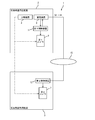
- FIG. 1 is a block diagram showing a schematic configuration of an oil residue-fired boiler system according to an embodiment of the present invention.
- FIG. 2 is a block diagram showing a configuration of a control system in the petroleum residue-fired boiler system shown in FIG.
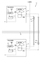
- FIG. 3 is a block diagram showing a schematic configuration of a petroleum residue-fired boiler system according to a modified example of the embodiment of the present invention.
- FIG. 1 is a block diagram showing a schematic configuration of an oil residue-fired boiler system according to an embodiment of the present invention.
- the fuel flow of crude oil or petroleum residue is indicated by a dashed arrow
- the flow of steam generated by the oil residue-fired boiler described later is indicated by a broken line arrow
- the control flow is indicated by a solid arrow. It is shown by.
- the petroleum residue-fired boiler system 1 includes a first boiler 9 provided in the petroleum residue supply facility 2 and a second boiler 7 provided in the petroleum residue utilization facility 3.
- the petroleum residue supply facility 2 is, for example, a refinery equipped with an oil refinery.
- the petroleum residue supply facility 2 includes a cracking device 4 that decomposes heavy oil to produce petroleum residues.
- the petroleum residue supply facility 2 is further provided with an atmospheric distillation apparatus 5.
- the atmospheric distillation apparatus 5 is configured to separate crude oil into a plurality of types of fractions (for example, naphtha, gasoline, light oil, heavy oil, etc.) that differ depending on the boiling point.
- the heavy oil separated by the atmospheric distillation apparatus 5 is supplied to the decomposition apparatus 4.
- the atmospheric distillation apparatus 5 discharges the atmospheric residual oil which is the residual residue after separating each fraction.
- the decomposition device 4 is configured to decompose heavy oil to extract a fraction having a lower boiling point such as gasoline. At this time, the decomposition apparatus 4 discharges the residual residue obtained by extracting the low boiling point fraction from the heavy oil as petroleum residue.
- the petroleum residue supply facility 2 may be provided with a vacuum distillation apparatus (not shown).
- the vacuum distillation apparatus further distills and separates the atmospheric residual oil separated by the atmospheric distillation apparatus 5 to take out the reduced pressure light oil.
- the vacuum distillation apparatus discharges the reduced pressure residual oil, which is the residue remaining after separating the reduced pressure gas oil.
- the petroleum refining apparatus includes at least one of the atmospheric distillation apparatus 5, the decomposition apparatus 4, and the vacuum distillation apparatus as described above.
- the petroleum residue supply facility 2 is equipped with a management device 6.
- the management device 6 is configured as a computer provided with an arithmetic unit, a storage device, and the like (not shown).
- the management device 6 acquires and manages data on the type, composition or properties (hereinafter, properties, etc.) of crude oil or petroleum residue.
- the petroleum residue supply facility 2 performs component analysis for each lot of crude oil to be supplied, and stores the properties and the like in the management device 6 together with the lot number.
- component analysis may be performed on crude oil or petroleum residues at different crude oil mining sites.
- the petroleum residue utilization facility 3 is equipped with a boiler (second boiler) 7 that generates steam.
- the second boiler 7 is an oil residue-fired boiler that uses petroleum residue as fuel.
- the second boiler 7 produces steam by burning the petroleum residue as fuel.
- the petroleum residue utilization facility 3 includes a steam utilization plant 8 that manufactures products using the steam generated by the second boiler 7.
- the petroleum residue utilization facility 3 is provided separately from the petroleum residue supply facility 2. That is, the petroleum residue supply facility 2 and the petroleum residue utilization facility 3 are clearly partitioned as different sections from each other. In the example of FIG. 1, the petroleum residue supply facility 2 and the petroleum residue utilization facility 3 are separated by at least one public road R1. The mode of the compartment is not limited to this. For example, the petroleum residue supply facility 2 and the petroleum residue utilization facility 3 may be separated by at least one fence and at least one private road. Further, the petroleum residue supply facility 2 and the petroleum residue utilization facility 3 may have different owners or businesses or users in the facilities 2 and 3.
- the petroleum residue utilization facility 3 is a factory facility that uses a large amount of steam, such as a petrochemical factory, a steel mill, a paper mill, and a power plant. For example, the petroleum residue utilization facility 3 is provided in the factory area.
- the oil residue supply facility 2 is also provided with a boiler (first boiler) 9.
- the first boiler 9 is also a petroleum residue-fired boiler.
- the petroleum residue supply facility 2 includes a steam utilization plant 10 that refines petroleum using the steam generated in the first boiler 9.
- the steam utilization plant 10 is shown as a separate facility from the decomposition device 4 and the atmospheric distillation apparatus 5 in FIG. 1, the steam utilization plant 10 also includes the decomposition apparatus 4 and the atmospheric distillation apparatus 5. included.
- the vacuum distillation apparatus is also included in the steam utilization plant 10.
- the decomposition device 4 and the atmospheric distillation device 5 steam is used to heat the raw material or the extracted fraction. Also in vacuum distillation equipment, steam is used to heat the raw material or the removed fraction. Further, the decomposition device 4 is provided with a stripper that blows steam into heavy oil to extract low boiling point components. The steam generated in the first boiler 9 is supplied to the decomposition apparatus 4 as steam (stripping steam) blown into heavy oil. Thus, in the decomposition apparatus 4 and the atmospheric distillation apparatus 5, steam is required to produce petroleum residues.
- the petroleum residue generated in the decomposition device 4 of the petroleum residue supply facility 2 is transported to the first boiler 9 in the facility and also to the second boiler 7 of the petroleum residue utilization facility 3.
- the transportation of the petroleum residue to the first boiler 9 or the second boiler 7 is performed when the petroleum residue is solid, for example, by a belt conveyor (not shown), and when the petroleum residue is liquid, for example, a residue supply pipe (shown). It may be done through.
- a truck equipped with a predetermined container for accommodating the petroleum residue or a predetermined container is loaded. It may be transported by truck or the like.
- the petroleum residue supply facility 2 is provided with a control device (first control device) 11 for controlling the first boiler 9.
- the petroleum residue utilization facility 3 is provided with a control device (second control device) 12 for controlling the second boiler 7.
- control devices 11 and 12 include a microcontroller, a storage device, an operation input device, and the like.
- the petroleum residue supply facility 2 can supply the steam generated by the first boiler 9 to an external steam utilization facility (not shown).
- the petroleum residue utilization facility 3 can supply the steam generated by the second boiler 7 to an external steam utilization facility (not shown). It should be noted that one or more external steam utilization facilities may or may not be provided. Further, there may be an external steam utilization facility capable of supplying steam from any of the petroleum residue supply facility 2 and the petroleum residue utilization facility 3.
- the oil residue supply facility 2 and the oil residue utilization facility 3 are provided with power generation devices (steam power generation devices) 41 and 42 that generate power using the steam generated by the boilers 9 and 7, respectively.
- the power generation devices 41 and 42 may be provided in the petroleum residue supply facility 2 or the petroleum residue utilization facility 3, or may be provided outside the facility.
- the steam supplied to the power generation devices 41 and 42 is exhausted after being used for power generation. This exhaust gas may be supplied to the steam utilization plants 10 and 8.
- FIG. 1 shows a configuration including one petroleum residue supply facility 2 and one petroleum residue utilization facility 3 as the petroleum residue burning boiler system 1.
- one petroleum residue supply facility 2 and a plurality of petroleum residue utilization facilities 3 may be provided.
- the configuration of the plurality of petroleum residue utilization facilities 3 may have the same configuration as the configuration of the petroleum residue utilization facility 3 described above, or the configuration other than the boiler 7 may be different.
- the second boiler 7 in the factory facility that uses a large amount of steam as the petroleum residue utilization facility 3, it is possible to realize a stable supply of steam in the factory facility (petroleum residue utilization facility 3). it can. Further, by making it possible to supply the steam generated in the petroleum residue utilization facility 3 to the petroleum residue supply facility 2, it is possible to exchange the steam between the petroleum residue supply facility 2 and the petroleum residue utilization facility 3. Further, of the steam generated by the second boiler 7, the ratio used in the factory facility and the ratio supplied to the power generation by the power generation device 42 can be planned and set more directly.
- the petroleum residue-fired boiler system 1 includes a steam supply line (steam return line) 18 for supplying the steam generated by the second boiler 7 to the petroleum residue supply facility 2.
- the steam return line 18 is composed of a steam supply pipe or the like connected to a steam discharge port (not shown) of the second boiler 7.
- steam is supplied to the oil residue supply facility 2 by steam generated by the second boiler 7, which is an oil residue burning boiler provided in the oil residue utilization facility 3 separated from the oil residue supply facility 2. It can be supplied through the line (steam return line) 18.
- the line (steam return line) 18 As a result, even if the first boiler 9 provided in the petroleum residue supply facility 2 is stopped or operated with the output limited due to a failure, repair, disaster, etc., an oil residue generator that produces petroleum residue.
- Steam can be supplied to the decomposition apparatus 4 or the atmospheric distillation apparatus 5 which is the above.
- the steam return line 18 is provided with an on-off valve 20 at least on the second boiler 7 side (downstream side in the steam flow direction), and is configured to be able to switch the flow or shutoff of steam through the steam return line 18.
- an on-off valve may be provided on the oil residue supply transfer 2 side (downstream side in the steam flow direction) of the steam return line 18.
- the second control device 12 may control the opening and closing of the on-off valve 20 when the steam generated by the second boiler 7 is conveyed through the steam return line 18. Instead of this, the on-off valve 20 may be manually opened and closed.
- the steam generated in the first boiler 9 can be supplied to the petroleum residue utilization facility 3.
- the oil residue-fired boiler system 1 may include a steam supply line (steam distribution line) for supplying the steam generated by the first boiler 9 to the petroleum residue utilization facility 3.
- a steam distribution line is composed of a steam supply pipe or the like connected to a steam discharge port (not shown) of the first boiler 9.
- the steam distribution line is provided with an on-off valve (not shown) at least on the first boiler 9 side (upstream side in the steam flow direction), and is configured to be able to switch the flow or shutoff of steam through the steam distribution line.
- the steam generated by the first boiler 9 can be supplied to the steam utilization plant 8 and the like of the petroleum residue utilization facility 3.
- the steam distribution line may be provided between the first boiler 9 and a steam utilization facility other than the petroleum residue utilization facility 3.
- the steam generated in the first boiler 9 can be supplied to the steam utilization facility without the oil residue utilization facility 3.
- the management device 6 of the petroleum residue supply facility 2 is configured to acquire the supply and demand information of steam in the petroleum residue supply facility 2.
- the management device 6 requests the petroleum residue utilization facility 3 to supply steam via the steam return line 18 based on the steam supply / demand information in the petroleum residue supply facility 2.
- the management device 6 is communicably connected to the steam utilization plant 10 including the atmospheric distillation apparatus 5 and the decomposition apparatus 4, and is configured to be able to acquire information on the amount of steam demand from the steam utilization plant 10.
- the management device 6 stores the amount of steam required by the steam amount plant 10 as the amount of steam demand in the petroleum residue supply facility 2.
- the management device 6 is communicably connected to an external steam utilization facility capable of supplying steam from the first boiler 9, and is configured to be able to acquire information on the amount of steam demand from the external steam utilization facility. May be good.
- the management device 6 stores the amount of steam obtained by adding the amount of steam required by the external steam utilization facility to the amount of steam required by the steam utilization plant 10 as the amount of steam demand in the petroleum residue supply facility 2. ..
- FIG. 2 is a block diagram showing a configuration of a control system in the oil residue-fired boiler system shown in FIG.
- the management device 6 of the petroleum residue supply facility 2 is communicably connected to the first control device 11 that controls the first boiler 9 in the petroleum residue supply facility 2.
- the management device 6 and the first control device 11 may be connected by a LAN or the like, or may be connected via the following predetermined communication network 15.
- the first control device 11 acquires information on the amount of steam generated by the first boiler 9 at a predetermined timing, and transmits the information to the management device 6.
- the management device 6 stores the steam production amount of the first boiler 9 acquired from the first control device 11 as the steam supply amount (the amount of steam that can be supplied from the first boiler 9) in the petroleum residue supply facility 2.
- management device 6 is communicably connected to the second control device 12 that controls the second boiler 7 in the petroleum residue utilization facility 3 via a predetermined communication network 15 such as the Internet.
- the steam request signal Sd is transmitted to the second boiler 7 (the second control device 12).
- the second boiler 7 controls the second boiler 7 so as to perform an operation so as to enable the oil residue supply facility 2 to supply steam. A part of the steam generated in the second boiler 7 is supplied to the petroleum residue supply facility 2 through the steam return line 18.
- the predetermined value Vth which is a reference for transmitting the steam request signal Sd, may be 0 or a positive value. That is, when the steam supply amount VS and the demand amount VD match, or when it is determined that the steam supply amount VS is larger than the demand amount VD but the steam demand amount VD may exceed the supply amount VS.
- the steam request signal Sd is transmitted to.
- the steam generated in the second boiler 7 can be supplied to the petroleum residue supply facility 2 when the supply-demand balance in the petroleum residue supply facility 2 becomes excessive demand or is likely to become excessive demand.
- the operation is such that the oil residue supply facility 2 can be supplied with steam, as compared with the operation before receiving the steam request signal Sd. Therefore, the amount of steam generated in the second boiler 7 is controlled to be increased.
- steam is supplied from the second boiler 7 provided in the petroleum residue utilization facility 3 to the oil residue supply facility 2 without suppressing the amount of steam used in the petroleum residue utilization facility 3. can do.
- the amount of steam supplied from the second boiler 7 to the oil residue supply facility 2 in one steam request signal Sd may be the amount of steam (insufficient amount) required in the oil residue supply facility 2.
- the steam request signal Sd includes information on the amount of steam shortage.
- the steam request signal Sd includes a shortage level
- the amount of steam supplied to the petroleum residue supply facility 2 corresponding to each of the plurality of shortage levels is stored in advance in the second control device 12.
- the second control device 12 reads out the shortage level included in the steam request signal Sd, and supplies the corresponding steam to the petroleum residue supply facility 2.
- the amount of steam supplied from the second boiler 7 to the petroleum residue supply facility 2 in one steam request signal Sd may be a predetermined amount regardless of the above difference ⁇ V.
- the steam request signal Sd may not include information about the amount of steam to be supplied to the petroleum residue supply facility 2.
- the second control device 12 is configured to control the second boiler 7 with different loads before and after receiving the steam request signal.
- the second boiler 7 produces a first steam amount V1 that is less than the maximum amount of steam that can be generated by the second boiler 7, and the amount of steam generated in the second boiler 7 ( Set as the first load).
- the first steam production amount V1 is set to 80% of the maximum amount VM.
- the second steam generation amount V2 which is larger than the first steam generation amount V1 is set as the steam generation amount (second load) in the second boiler 7.
- the second steam production amount V2 is set to the maximum amount of steam VM (100%) that the second boiler 7 can generate.
- the amount of steam produced by the second boiler 7 is not supplied to the oil residue supply facility 2, the amount of steam produced by the second boiler 7 is less than the maximum amount of steam that can be generated by the second boiler 7, and the remaining capacity is left.
- the amount of steam used in the oil residue utilization facility 3 and the steam generated in the oil residue utilization facility 3 are supplied (supplied) to the external facility using the steam before the start of the supply of steam to the oil residue supply facility 2. It is possible to prevent the amount of steam (possible) from becoming insufficient.
- the management device 6 can continue to acquire steam supply / demand information at the petroleum residue supply facility 2 even when steam is supplied from the second boiler 7. For example, when the steam return line 18 is laid between the petroleum residue supply facility 2 and the plurality of petroleum residue utilization facilities 3, the management device 6 uses the oil of any one of the plurality of petroleum residue utilization facilities 3. The steam request signal Sd is transmitted to the second boiler 7 provided in the residue utilization facility 3.
- the steam request signal Sd is transmitted to the second boiler 7 provided in the other petroleum residue utilization facility 3 among the plurality of oil residue utilization facilities 3.
- the steam supply amount VS also includes the steam amount already supplied from the petroleum residue utilization facility 3 (second boiler 7).
- the management device 6 transmits a steam request signal Sd to all of the plurality of second control devices 12 that control the plurality of second boilers 7 capable of supplying steam to the oil residue supply facility 2, and each second control device.
- the second boiler 7 which is configured to receive the reply of the steam supply availability signal from 12 and supplies steam may be determined based on the information contained in the steam supply availability signal.
- the distance between the oil residue supply facility 2 and the oil residue utilization facility 3 (the length of the steam return line 18). May be used to set the priority for selecting the petroleum residue utilization facility 3 in ascending order of distance.
- the supply and demand information at each petroleum residue utilization facility 3 when the steam request signal Sd is transmitted is used, and the order in which the steam supply is available (for example, the order in which the amount obtained by subtracting the demand amount from the supply amount is large) is used.
- the priority for selecting the petroleum residue utilization facility 3 may be set.
- the operating status of the second boiler 7 provided in each petroleum residue utilization facility 3 when transmitting the steam request signal Sd (the ratio of the current steam production amount to the maximum amount of steam that can be generated VM ( %)) May be used to set the priority for selecting the petroleum residue utilization facility 3 in ascending order of load (lower ratio).
- the steam supply availability signal includes information on the supply and demand status of the oil residue utilization facility 3.
- the steam supply availability signal includes information on the operating status of the second boiler 7.
- the steam request signal Sd may be transmitted to all the petroleum residue utilization facilities 3 and steam may be supplied from all the second boilers 7 that have received the steam request signal Sd without setting a priority.
- the amount of steam supplied to the petroleum residue supply facility 2 or the ratio thereof may be preset for each second boiler 7.
- the first control device 11 transmits a steam request signal Sd to the second boiler 7 when the amount of steam generated in the first boiler 9 becomes a predetermined value VG or less. Therefore, the second control device 12 of the second boiler 7 enables the second boiler 7 to supply steam to the petroleum residue supply facility 2 when the amount of steam generated in the first boiler 9 becomes a predetermined value VG or less. Such an operation is performed to supply steam to the petroleum residue supply facility 2.
- the steam generated in the second boiler 7 can be supplied to the petroleum residue supply facility 2. Therefore, for example, if the first boiler 9 is stopped due to a failure, or if the first boiler 9 cannot be operated due to the repair work, a disaster or the like occurs in the oil residue supply facility 2, and the first boiler 9 is stopped or output. Even when restricted operation such as restriction is performed, it is possible to secure the steam supply amount VS in the petroleum residue supply facility 2.
- the second control device 12 transfers a predetermined amount of the steam generated by the second boiler 7 from the second boiler 7 to the power generation device 42 so as to supply the power generation device 42. It controls the amount of steam supplied.
- the predetermined amount of steam supplied to the power generation device 42 may be an absolute amount or an amount based on a predetermined ratio with respect to the amount of steam generated in the second boiler 7.
- the second control device 12 reduces the amount of steam supplied from the second boiler 7 to the power generation device 42 as an operation that enables the oil residue supply facility 2 to be supplied with steam. It may be controlled to do so.
- the reduced amount of steam is supplied to the petroleum residue supply facility 2.
- 50% of the steam generated in the petroleum residue utilization facility 3 is supplied to the power generation device 42, and steam is supplied to the petroleum residue supply facility 2.
- 30% of the amount of steam generated in the second boiler 7 may be supplied to the power generation device 42, and 20% of the difference may be supplied to the petroleum residue supply facility 2.
- the control for reducing the amount of steam supplied to the power generation device 42 may be executed independently (in parallel) with the control for increasing the amount of steam generated by the second boiler 7.
- the second control device 12 preferentially executes control for increasing the amount of steam generated in the second boiler 7, and generates electricity when it becomes necessary to supply steam to the petroleum residue supply facility 2.
- Control may be performed to reduce the supply of steam to the device 42.
- the second control device 12 sends the second control device 12 to the power generation device 42. Controls may be performed to reduce the supply of steam.
- the second control device 12 reduces the amount of steam supplied to the power generation device 42. Control may be performed.
- the oil residue-fired boiler is exemplified as the first boiler 9 provided in the petroleum residue supply facility 2, but the first boiler 9 may be a boiler other than the petroleum residue-fired boiler.
- the first boiler 9 applies various boilers such as a gas-fired boiler that uses a predetermined gas as fuel, a boiler that uses fossil fuel such as a coal-fired boiler, and an exhaust heat boiler that utilizes exhaust heat from an incinerator or the like. It is possible.
- the petroleum residue-fired boiler used as the second boiler 7 any boiler may be used as long as the petroleum residue is used as fuel, such as a staged combustion type dedicated combustion boiler.
- the petroleum residue supply facility 2 may be provided with a steam generator other than the boiler using a gas turbine or the like instead of the first boiler 9.
- the petroleum residue supply facility 2 is configured as a petroleum refining facility provided with an atmospheric distillation apparatus 5 and a cracking apparatus 4.
- the cracking device 4 is configured as a petroleum residue generating device that produces petroleum residues. Therefore, the petroleum residue supply facility 2 does not have to be equipped with a petroleum refining facility such as an atmospheric distillation apparatus 5. That is, the petroleum residue supply facility 2 may be configured as a facility separate from the petroleum refining facility. On the contrary, the petroleum residue supply facility 2 may be provided with the atmospheric distillation apparatus 5 and may not be provided with the decomposition apparatus 4. In this case, the atmospheric residual oil or the like generated by the atmospheric distillation apparatus 5 may be transported to the petroleum residue utilization facility 3 as petroleum residue.
- the petroleum residue producing apparatus may be an atmospheric distillation apparatus 5.
- the petroleum residue supply facility 2 is equipped with a vacuum distillation apparatus
- the reduced pressure residual oil or the like generated by the vacuum distillation apparatus may be transported to the petroleum residue utilization facility 3 as petroleum residues.
- the petroleum residue producing apparatus may be a vacuum distillation apparatus.
- the petroleum residue in the present specification and claims includes residual oil or flame-retardant oil produced in various devices such as a distillation device, a decomposition device or a solvent removal device in a petroleum refining process.
- the mode in which the steam supply is requested to the second boiler 7 of the petroleum residue utilization facility 3 based on the amount is described, the mode in which only one of the modes is performed may be executed.
- the mode in which the amount of steam generated by the second boiler 7 is reduced in the case where the steam is not supplied to the petroleum residue supply facility 2 as compared with the case where the steam is supplied has been described. 2
- the amount of steam produced by the boiler 7 may not change depending on whether or not steam is supplied to the petroleum residue supply facility 2. For example, when supplying steam to the petroleum residue supply facility 2, the steam supply to the predetermined steam utilization plant 8 or the steam utilization facility 14 may be stopped or the steam supply amount may be reduced.
- the mode in which the steam generated by the second boiler 7 is supplied to the petroleum residue supply facility 2 through the steam return line 18 has been described, but the steam generated by the first boiler 9 is steamed.
- the control mode described in the above embodiment can be applied to the case of supplying the petroleum residue utilization facility 3 through the distribution line.
- FIG. 3 is a block diagram showing a schematic configuration of a petroleum residue-fired boiler system according to a modified example of the embodiment of the present invention.
- the same components as those of FIG. 1 are designated by the same reference numerals, and the description thereof will be omitted.
- the first steam generation facility 31 provided with the steam generating boiler 71 and the first steam generation facility 31 are provided apart from each other, and the steam generating boiler 72 is provided. It is equipped with a second steam generation facility 32.
- the boilers 71 and 72 are configured as petroleum residue-fired boilers. Therefore, the steam generation facilities 31 and 32 correspond to the petroleum residue utilization facility 3 in the above embodiment.
- the petroleum residue boiler system 1B includes a first steam supply line 51 for supplying the steam generated by the boiler 71 in the first steam generation facility 31 to the second steam generation facility 32. Further, the petroleum residue-fired boiler system 1B includes a second steam supply line 52 for supplying the steam generated by the boiler 72 in the second steam generation facility 32 to the first steam generation facility 31.
- the control mode described in the above embodiment can be similarly applied to the steam transfer control through the steam supply lines 51 and 52.
- the steam generated by the boiler 71 of the first steam generation facility 31 is supplied to the second steam generation facility 32 by opening the on-off valve 53 provided in the first steam supply line 51. can do.
- the on-off valve 54 provided in the steam supply line 52 the steam generated by the boiler 72 of the second steam generation facility 32 can be supplied to the first steam generation facility 31.
- steam can be interchanged between the plurality of steam generation facilities 31 and 32 provided with the boilers 71 and 72 through the steam supply lines 51 and 52.
- the steam generation facilities 31 and 32 generate the steam used in the steam generation facilities 31 and 32 and supply the steam
- the oil residue used as the fuel for the boilers 71 and 72 may be insufficient, or If the boilers 71 and 72 are stopped or operated with limited output due to a failure, repair or disaster, the steam supply at the steam generation facilities 31 and 32 will be delayed, and various processing processes using steam will be delayed. There will be an effect such as
- the description is based on the case where the boilers 71 and 72 are oil residue-fired boilers.
- the boilers 71 and 72 are , Boilers other than oil residue-fired boilers (for example, the above-mentioned gas-fired boilers, boilers using fossil fuels, exhaust heat boilers, etc.) may be used.
- steam supply lines 51 and 52 in the same manner in three or more steam generation facilities.
- it may be a common steam supply line 52 in some steam generation facilities.
- there may be a steam generation facility in which steam is not supplied from another steam generation facility, or a steam supply facility in which steam is not supplied to the other steam generation facility.
- FIG. 3 a configuration in which the steam supply direction is constant in the steam supply lines 51 and 52 is illustrated. That is, a first steam supply line 51 that supplies steam to the second steam generation facility 32 and a second steam supply line 52 that supplies steam to the first steam generation facility 31 are individually provided.
- the steam supply lines 51 and 52 may be configured as a common line, and the steam supply direction may be switched depending on the case.
- the mode in which the management device 6 for acquiring the supply and demand information of steam in the petroleum residue supply facility 2 is provided in the petroleum residue supply facility 2 has been described. That is, according to the above embodiment, when the oil residue supply facility 2 acquires the supply and demand information of steam in the oil residue supply facility 2, and the supply and demand balance in the oil residue supply facility 2 becomes excessive or excessive demand. In the case of such a situation, the second boiler 7 in the petroleum residue utilization facility 3 is notified to request steam, and the steam is supplied from the second boiler 7 to the petroleum residue supply facility 2. From a different standpoint, in the oil residue utilization facility 3, when the supply and demand balance in the oil residue supply facility 2 becomes excessive or is likely to become excessive based on the steam supply and demand information in the oil residue supply facility 2. The amount of steam produced in the second boiler 7 is increased, and steam is supplied to the petroleum residue supply facility 2 through the steam return line 18.
- the management device 6 may be provided in the petroleum residue utilization facility 3.
- the management device 6 in the petroleum residue utilization facility 3 acquires the steam supply / demand information in the petroleum residue supply facility 2, and the steam request signal is sent to the second control device 12 of the petroleum residue supply facility 2 provided with the control device 6. Sd may be transmitted. That is, in the petroleum residue supply facility 2, the supply and demand information of steam in the petroleum residue supply facility 2 may be notified to the petroleum residue utilization facility 3, and the steam may be supplied from the second boiler 7 to the petroleum residue supply facility 2.
- the oil residue utilization facility 3 acquires the steam supply and demand information in the oil residue supply facility 2, and whether or not the supply and demand balance in the oil residue supply facility 2 has become excessive or is likely to become excessive. If the supply-demand balance in the oil residue supply facility 2 becomes excessive or is likely to become excessive, the amount of steam generated in the second boiler 7 is increased, and oil is produced through the steam return line 18. Steam may be supplied to the residue supply facility 2.
- the mode in which the first control device 11 transmits the steam request signal Sd to the second boiler 7 when the amount of steam generated in the first boiler 9 becomes equal to or less than a predetermined value will be described. did. That is, according to the above embodiment, in the oil residue supply facility 2, it is determined whether or not the amount of steam generated in the first boiler 9 is equal to or less than a predetermined value, and if it is equal to or less than a predetermined value, the oil residue is used. The second boiler 7 in the facility 3 is notified to request steam, and the steam is supplied from the second boiler 7 to the petroleum residue supply facility 2. From a different standpoint, when the amount of steam produced in the first boiler 9 falls below a predetermined value in the oil residue utilization facility 3, the amount of steam produced in the second boiler 7 is increased and the oil residue is supplied through the steam return line 18. Supply steam to facility 2.
- the management device or the second control device 12 provided in the petroleum residue utilization facility 3 may determine whether or not the amount of steam generated in the first boiler 9 is equal to or less than a predetermined value.
- the first boiler 9 periodically transmits information on the amount of steam generated in the first boiler 9 to the petroleum residue utilization facility 3, and the management device or the second control device 12 of the oil residue utilization facility 3 periodically transmits the information. It is determined whether or not the amount of steam generated is equal to or less than a predetermined value based on. That is, in the petroleum residue supply facility 2, the information on the amount of steam produced in the first boiler 9 may be notified to the petroleum residue utilization facility 3, and the steam may be supplied from the second boiler 7 to the petroleum residue supply facility 2.
- the oil residue utilization facility 3 acquires information on the amount of steam produced in the first boiler 9, determines whether or not the amount of steam produced in the first boiler 9 is below a predetermined value, and determines whether or not the amount of steam produced in the first boiler 9 is equal to or less than a predetermined value.
- the amount of steam produced in No. 9 becomes equal to or less than a predetermined value
- the amount of steam produced in the second boiler 7 may be increased to supply steam to the oil residue supply facility 2 through the steam return line 18.
- the management device 6 may be provided in a facility other than the petroleum residue supply facility 2 and the petroleum residue utilization facility 3.
- the management device 6 may be provided in the petroleum residue supply facility 2 or the petroleum residue utilization facility 3, or may be provided in a facility other than these facilities 2 and 3.
- the management device 6 acquires information on the supply and demand of steam in the oil residue supply facility 2 and / or information on the amount of steam produced in the first boiler 9, and determines the necessity of steam.
- the management device 6 notifies the second boiler 7 (the second control device 12) of the petroleum residue utilization facility 3 to request steam when it is determined that steam is required at the petroleum residue supply facility 2. By doing so (for example, transmitting a steam request signal), the steam of the second boiler 7 is supplied to the first boiler 9. In this way, the above-mentioned exchange between the petroleum residue supply facility 2 and the petroleum residue utilization facility 3 may be performed via another facility (or device).
- management device 6 and / or the first control device 11 provided in the petroleum residue supply facility 2 may be configured as the equipment of the petroleum residue utilization facility 3.
- the second control device 12 when the second control device 12 receives the steam request signal Sd, the mode of controlling the second boiler 7 to increase the amount of steam generated has been described.
- the worker of the oil residue utilization facility 3 operates the second boiler 7 so as to increase the amount of steam generated in the second boiler 7 when the amount of steam in the oil residue supply facility 2 is insufficient.
- the steam generated in the second boiler 7 may be supplied to the oil residue supply facility 2 through the steam return line 18 (opening operation of the on-off valve 20).
- the petroleum residue supply facility 2 may notify the petroleum residue utilization facility 3 of the steam supply request by telephone or the like.
- the present invention is useful for stably supplying petroleum residues to petroleum residue utilization facilities.
Landscapes
- Engineering & Computer Science (AREA)
- Physics & Mathematics (AREA)
- Thermal Sciences (AREA)
- Mechanical Engineering (AREA)
- General Engineering & Computer Science (AREA)
- Chemical & Material Sciences (AREA)
- Combustion & Propulsion (AREA)
- Control Of Steam Boilers And Waste-Gas Boilers (AREA)
- Fluidized-Bed Combustion And Resonant Combustion (AREA)
- Feeding And Controlling Fuel (AREA)
Abstract
Description
2 石油残渣供給施設
3 石油残渣利用施設
31,32 蒸気生成施設
6 管理装置
7 第2ボイラ
9 第1ボイラ
11 第1制御装置
12 第2制御装置
18 蒸気戻りライン(蒸気供給ライン)
Claims (8)
- 石油残渣を生成する石油残渣供給施設に設けられた第1ボイラと、
前記石油残渣供給施設とは離隔した石油残渣利用施設に設けられ、前記石油残渣供給施設から搬送された前記石油残渣を燃料とする第2ボイラと、
前記第2ボイラで生成される蒸気を前記石油残渣供給施設に供給するための蒸気供給ラインと、を備えた、ボイラシステム。 - 前記石油残渣供給施設における蒸気の需給情報を取得する管理装置を備え、
前記管理装置は、前記石油残渣供給施設における蒸気の供給量から前記石油残渣供給施設における蒸気の需要量を差し引いた差が所定値以下となった場合に、前記第2ボイラに対して蒸気要求信号を送信し、
前記第2ボイラは、前記蒸気要求信号を受信した場合、前記石油残渣供給施設に蒸気を供給可能にさせるような運転を行う、請求項1に記載のボイラシステム。 - 前記第1ボイラを制御する第1制御装置を備え、
前記第1制御装置は、前記第1ボイラにおける蒸気生成量が所定値以下となった場合に、前記第2ボイラに対して蒸気要求信号を送信し、
前記第2ボイラは、前記蒸気要求信号を受信した場合、前記石油残渣供給施設に蒸気を供給可能にさせるような運転を行う、請求項1または2に記載のボイラシステム。 - 前記第2ボイラを制御する第2制御装置を備え、
前記第2制御装置は、前記蒸気要求信号を受信した場合に、前記蒸気要求信号を受信する前に比べて前記第2ボイラにおける蒸気生成量を増大させるように制御する、請求項2または3に記載のボイラシステム。 - 前記第2制御装置は、前記蒸気要求信号を受信していない場合に、前記第2ボイラが生成可能な蒸気の最大量より少ない第1蒸気生成量を、前記第2ボイラにおける蒸気生成量として設定し、前記蒸気要求信号を受信した場合に、前記第1蒸気生成量より多い第2蒸気生成量を、前記第2ボイラにおける蒸気生成量として設定する、請求項4に記載のボイラシステム。
- 前記第2ボイラで生成された蒸気を用いて発電を行う発電装置と、
前記第2ボイラを制御する第2制御装置と、を備え、
前記第2制御装置は、前記第2ボイラで生成される蒸気生成量のうちの所定量を前記発電装置に供給するように前記第2ボイラから前記発電装置への蒸気の供給量を制御し、前記蒸気要求信号を受信した場合に、前記第2ボイラから前記発電装置への蒸気の供給量を低減するように制御する、請求項2から5の何れかに記載のボイラシステム。 - 前記第2ボイラで生成された蒸気を用いて発電を行う発電装置と、
前記第2ボイラを制御する第2制御装置と、を備え、
前記第2制御装置は、
前記蒸気要求信号を受信した場合に、前記蒸気要求信号を受信する前に比べて前記第2ボイラにおける蒸気生成量を増大させるように制御し、
前記第2ボイラにおける蒸気生成量を増大している状態で、さらに前記石油残渣供給施設への蒸気の供給が必要となった場合に、前記第2ボイラから前記発電装置への蒸気の供給量を低減するように制御する、請求項2または3に記載のボイラシステム。 - それぞれが互いに離隔して設けられ、蒸気を生成するボイラを備えた複数の蒸気生成施設と、
一の蒸気生成施設における前記ボイラで生成される蒸気を他の蒸気生成施設に供給するための蒸気供給ラインと、を備えた、ボイラシステム。
Priority Applications (2)
| Application Number | Priority Date | Filing Date | Title |
|---|---|---|---|
| BR112021019868-7A BR112021019868B1 (pt) | 2019-04-05 | 2020-04-06 | Sistema de caldeira |
| SA521430455A SA521430455B1 (ar) | 2019-04-05 | 2021-09-29 | نظام غلاية |
Applications Claiming Priority (2)
| Application Number | Priority Date | Filing Date | Title |
|---|---|---|---|
| JP2019-073133 | 2019-04-05 | ||
| JP2019073133A JP7330612B2 (ja) | 2019-04-05 | 2019-04-05 | ボイラシステム |
Publications (1)
| Publication Number | Publication Date |
|---|---|
| WO2020204203A1 true WO2020204203A1 (ja) | 2020-10-08 |
Family
ID=72669073
Family Applications (1)
| Application Number | Title | Priority Date | Filing Date |
|---|---|---|---|
| PCT/JP2020/015475 Ceased WO2020204203A1 (ja) | 2019-04-05 | 2020-04-06 | ボイラシステム |
Country Status (3)
| Country | Link |
|---|---|
| JP (1) | JP7330612B2 (ja) |
| SA (1) | SA521430455B1 (ja) |
| WO (1) | WO2020204203A1 (ja) |
Citations (12)
| Publication number | Priority date | Publication date | Assignee | Title |
|---|---|---|---|---|
| JPS63117107A (ja) * | 1986-11-05 | 1988-05-21 | Hitachi Ltd | 補助蒸気装置 |
| JPH11270354A (ja) * | 1998-03-20 | 1999-10-05 | Mitsubishi Heavy Ind Ltd | 火力発電所 |
| JPH11270355A (ja) * | 1998-03-20 | 1999-10-05 | Mitsubishi Heavy Ind Ltd | 排気再燃火力発電設備 |
| JP2000273467A (ja) * | 1998-10-30 | 2000-10-03 | Jgc Corp | ガスタ−ビン燃料油及びその製造方法並びに発電方法 |
| JP2009300054A (ja) * | 2008-06-17 | 2009-12-24 | Ihi Corp | 石油残渣の燃料供給方法及び装置 |
| JP2012215340A (ja) * | 2011-03-31 | 2012-11-08 | Mitsubishi Heavy Ind Ltd | 蒸気送気システム及び蒸気送気方法 |
| JP2014156936A (ja) * | 2013-02-14 | 2014-08-28 | Miura Co Ltd | ボイラシステム |
| JP2015017713A (ja) * | 2013-07-08 | 2015-01-29 | 有限会社庄野環境デザインラボ | 熱媒供給方法、熱媒製造システム、コジェネレーション装置の導入方法、およびコジェネレーションシステム |
| JP2017031859A (ja) * | 2015-07-31 | 2017-02-09 | 三菱日立パワーシステムズ株式会社 | 複合サイクル発電プラント及びその制御方法 |
| JP2017138014A (ja) * | 2016-02-01 | 2017-08-10 | 三菱日立パワーシステムズ株式会社 | 石油残渣の混合油生成方法、混合油生成装置及びボイラシステム |
| WO2018065919A1 (en) * | 2016-10-07 | 2018-04-12 | Sabic Global Technologies B.V. | Process and a system for hydrocarbon steam cracking |
| WO2018065922A1 (en) * | 2016-10-07 | 2018-04-12 | Sabic Global Technologies B.V. | Process and a system for generating hydrocarbon vapor |
Family Cites Families (4)
| Publication number | Priority date | Publication date | Assignee | Title |
|---|---|---|---|---|
| JPH1119504A (ja) * | 1997-07-07 | 1999-01-26 | Jgc Corp | 異業種複合基盤産業プラント集合体 |
| JP2001050011A (ja) | 1999-08-04 | 2001-02-23 | Jgc Corp | 石油燃料燃焼コンバインドサイクル発電施設及びその発電施設の運転方法。 |
| JP2002063245A (ja) | 2000-08-22 | 2002-02-28 | Idemitsu Kosan Co Ltd | コンビナート、コンビナートの運営方法、蒸気管理システムおよび記録媒体 |
| JP4634538B1 (ja) | 2010-05-27 | 2011-02-16 | 住友商事株式会社 | ハイブリッド火力発電システム及びその建造方法 |
-
2019
- 2019-04-05 JP JP2019073133A patent/JP7330612B2/ja active Active
-
2020
- 2020-04-06 WO PCT/JP2020/015475 patent/WO2020204203A1/ja not_active Ceased
-
2021
- 2021-09-29 SA SA521430455A patent/SA521430455B1/ar unknown
Patent Citations (12)
| Publication number | Priority date | Publication date | Assignee | Title |
|---|---|---|---|---|
| JPS63117107A (ja) * | 1986-11-05 | 1988-05-21 | Hitachi Ltd | 補助蒸気装置 |
| JPH11270354A (ja) * | 1998-03-20 | 1999-10-05 | Mitsubishi Heavy Ind Ltd | 火力発電所 |
| JPH11270355A (ja) * | 1998-03-20 | 1999-10-05 | Mitsubishi Heavy Ind Ltd | 排気再燃火力発電設備 |
| JP2000273467A (ja) * | 1998-10-30 | 2000-10-03 | Jgc Corp | ガスタ−ビン燃料油及びその製造方法並びに発電方法 |
| JP2009300054A (ja) * | 2008-06-17 | 2009-12-24 | Ihi Corp | 石油残渣の燃料供給方法及び装置 |
| JP2012215340A (ja) * | 2011-03-31 | 2012-11-08 | Mitsubishi Heavy Ind Ltd | 蒸気送気システム及び蒸気送気方法 |
| JP2014156936A (ja) * | 2013-02-14 | 2014-08-28 | Miura Co Ltd | ボイラシステム |
| JP2015017713A (ja) * | 2013-07-08 | 2015-01-29 | 有限会社庄野環境デザインラボ | 熱媒供給方法、熱媒製造システム、コジェネレーション装置の導入方法、およびコジェネレーションシステム |
| JP2017031859A (ja) * | 2015-07-31 | 2017-02-09 | 三菱日立パワーシステムズ株式会社 | 複合サイクル発電プラント及びその制御方法 |
| JP2017138014A (ja) * | 2016-02-01 | 2017-08-10 | 三菱日立パワーシステムズ株式会社 | 石油残渣の混合油生成方法、混合油生成装置及びボイラシステム |
| WO2018065919A1 (en) * | 2016-10-07 | 2018-04-12 | Sabic Global Technologies B.V. | Process and a system for hydrocarbon steam cracking |
| WO2018065922A1 (en) * | 2016-10-07 | 2018-04-12 | Sabic Global Technologies B.V. | Process and a system for generating hydrocarbon vapor |
Also Published As
| Publication number | Publication date |
|---|---|
| JP7330612B2 (ja) | 2023-08-22 |
| BR112021019868A2 (pt) | 2021-12-07 |
| JP2020169793A (ja) | 2020-10-15 |
| SA521430455B1 (ar) | 2024-08-08 |
Similar Documents
| Publication | Publication Date | Title |
|---|---|---|
| US12450671B2 (en) | Blockchain mining system with load modulation | |
| RU2018140018A (ru) | Экологичное судовое топливо | |
| US20160344186A1 (en) | Generator management system that selectively activates generators based on an operating parameter | |
| JP5167158B2 (ja) | 液化燃料運搬船およびその推進システム | |
| US20230285920A1 (en) | Method and device for recycling waste materials containing valuable metals | |
| JP7330612B2 (ja) | ボイラシステム | |
| KR20130091135A (ko) | 부유식 구조물 | |
| US8021537B2 (en) | Steam generation apparatus and method | |
| Gray | Decrease in fly ash spurring innovation within construction materials industry | |
| CN100504054C (zh) | 烧重质油改质燃料的燃气轮机系统及其运转方法 | |
| US5911875A (en) | Method and system for generating power from residual fuel oil | |
| JP5442469B2 (ja) | 余剰bogの有効活用方法 | |
| CN105264293A (zh) | 用于处理重质渣油的系统和方法 | |
| KR101694437B1 (ko) | 연료 공급장치, 연료 공급방법 및 발전 시스템 | |
| JP7284618B2 (ja) | 石油残渣焚きボイラシステムの制御装置 | |
| WO2020204204A1 (ja) | 石油残渣焚きボイラシステムおよび石油残渣焚きボイラを用いた石油残渣の燃焼制御方法 | |
| Soliman | Beyond Zero Flaring & Monetization Strategies in Global Circular Carbon Economy | |
| KR20130070855A (ko) | 선박용 비상발전기 전원공급방법 | |
| US20240318087A1 (en) | Mobile hydrocarbon refineries and related methods | |
| Nalinakshan et al. | Simulation, optimisation and analysis of energy saving in crude oil distillation unit | |
| Ba-Shammakh | Generalized mathematical model for SO2 reduction in an oil refinery based on Arabian light crude oil | |
| JPH11270354A (ja) | 火力発電所 | |
| JPH06207530A (ja) | コンバインド・サイクル発電方法 | |
| JP4402531B2 (ja) | 重質油改質装置と改質方法、ガスタービン発電装置および石油精製装置 | |
| WO2008049201A1 (en) | Steam generation apparatus and method |
Legal Events
| Date | Code | Title | Description |
|---|---|---|---|
| 121 | Ep: the epo has been informed by wipo that ep was designated in this application |
Ref document number: 20784577 Country of ref document: EP Kind code of ref document: A1 |
|
| NENP | Non-entry into the national phase |
Ref country code: DE |
|
| REG | Reference to national code |
Ref country code: BR Ref legal event code: B01A Ref document number: 112021019868 Country of ref document: BR |
|
| ENP | Entry into the national phase |
Ref document number: 112021019868 Country of ref document: BR Kind code of ref document: A2 Effective date: 20211004 |
|
| 122 | Ep: pct application non-entry in european phase |
Ref document number: 20784577 Country of ref document: EP Kind code of ref document: A1 |
|
| WWE | Wipo information: entry into national phase |
Ref document number: 521430455 Country of ref document: SA |
|
| WWE | Wipo information: entry into national phase |
Ref document number: 521430455 Country of ref document: SA |
|
| WWG | Wipo information: grant in national office |
Ref document number: 521430455 Country of ref document: SA |