WO2020204080A1 - テザー及び人工天体 - Google Patents
テザー及び人工天体 Download PDFInfo
- Publication number
- WO2020204080A1 WO2020204080A1 PCT/JP2020/015045 JP2020015045W WO2020204080A1 WO 2020204080 A1 WO2020204080 A1 WO 2020204080A1 JP 2020015045 W JP2020015045 W JP 2020015045W WO 2020204080 A1 WO2020204080 A1 WO 2020204080A1
- Authority
- WO
- WIPO (PCT)
- Prior art keywords
- tether
- atomic oxygen
- tether according
- carbon
- spun yarn
- Prior art date
- Legal status (The legal status is an assumption and is not a legal conclusion. Google has not performed a legal analysis and makes no representation as to the accuracy of the status listed.)
- Ceased
Links
- 0 CC*1ClCC(CC)=C1 Chemical compound CC*1ClCC(CC)=C1 0.000 description 1
Images


Classifications
-
- B—PERFORMING OPERATIONS; TRANSPORTING
- B64—AIRCRAFT; AVIATION; COSMONAUTICS
- B64G—COSMONAUTICS; VEHICLES OR EQUIPMENT THEREFOR
- B64G1/00—Cosmonautic vehicles
- B64G1/22—Parts of, or equipment specially adapted for fitting in or to, cosmonautic vehicles
-
- C—CHEMISTRY; METALLURGY
- C01—INORGANIC CHEMISTRY
- C01B—NON-METALLIC ELEMENTS; COMPOUNDS THEREOF; METALLOIDS OR COMPOUNDS THEREOF NOT COVERED BY SUBCLASS C01C
- C01B32/00—Carbon; Compounds thereof
- C01B32/15—Nano-sized carbon materials
- C01B32/158—Carbon nanotubes
- C01B32/168—After-treatment
-
- D—TEXTILES; PAPER
- D04—BRAIDING; LACE-MAKING; KNITTING; TRIMMINGS; NON-WOVEN FABRICS
- D04C—BRAIDING OR MANUFACTURE OF LACE, INCLUDING BOBBIN-NET OR CARBONISED LACE; BRAIDING MACHINES; BRAID; LACE
- D04C1/00—Braid or lace, e.g. pillow-lace; Processes for the manufacture thereof
- D04C1/02—Braid or lace, e.g. pillow-lace; Processes for the manufacture thereof made from particular materials
-
- D—TEXTILES; PAPER
- D04—BRAIDING; LACE-MAKING; KNITTING; TRIMMINGS; NON-WOVEN FABRICS
- D04C—BRAIDING OR MANUFACTURE OF LACE, INCLUDING BOBBIN-NET OR CARBONISED LACE; BRAIDING MACHINES; BRAID; LACE
- D04C1/00—Braid or lace, e.g. pillow-lace; Processes for the manufacture thereof
- D04C1/06—Braid or lace serving particular purposes
Definitions
- the present invention relates to, for example, tethers and artificial celestial bodies used to remove debris in outer space.
- a tether with a length of several hundred meters to several tens of kilometers has been demonstrated in outer space.
- the tether is launched into outer space in a wound state, and is extended by releasing the end mass attached to one end of the tether at a speed of several m / s per second with a spring or the like (see Non-Patent Document 1).
- the present inventors have proposed a lightweight, space-saving, and high-strength tether for space (see Patent Document 1).
- conductive tethers generate thrust (Lorentz force) by interacting with the earth's magnetic field while passing an electric current through an induced electromotive force or an external power source, and are promising because they can reduce costs. There is.
- the conductive tether was expected to be able to lower the orbital altitude of debris and remove debris in operation for several months to one year.
- the present inventors have proposed a technique related to a tether that kinks and deforms autonomously when tension is released, that is, focuses when tension is lost.
- the long tether will be in a focused state to reduce the burden of collision avoidance and the risk of collision with operational satellites. Can be done.
- An object of the present invention is to provide a tether and an artificial celestial body that can further reduce the burden of avoiding collisions with operating satellites and the risk of collisions.
- the tether according to one embodiment of the present invention is composed of a member in which at least a part of a region in the length direction is disintegrated or disappears by exposure to atomic oxygen.
- the entire tether consists of the members.
- a part of the tether in the length direction is made of the member.
- the region made up of the members is typically located close to the spacecraft.
- the member typically has conductivity.
- Tether collides with atomic oxygen at orbital speed in outer space.
- the region that collapses or disappears due to exposure to atomic oxygen and is composed of a conductive member constitutes part or all of the tether and exerts a function as a tether, but the atomic oxygen Since it is gasified and disappears due to exposure, even if the tether remains in outer space with a length of several hundred meters to several tens of kilometers, such as when the tether is cut or malfunctions, it will eventually disappear.
- it can be decomposed into fine fragments that fall from the orbit quickly under the influence of atmospheric resistance, or descend from the orbit together with the end mass and the like so that they do not remain in outer space.
- the burden of avoiding collisions with operational satellites and the risk of collisions can be further reduced.
- the member is preferably made of a nanocarbon material made of SP2-bonded carbon.
- a nanocarbon material made of SP2-bonded carbon carbon nanotubes, graphene, carbon nanofivers, or carbon nanocoils are suitable.
- the member may be defective or damaged.
- a member originally having many defects may be used.
- the defect may be macroscopic damage to the spun yarn or small yarn constituting the tether, or may be nano-level damage to the crystal structure of the nanocarbon material itself.
- after the tether body is manufactured it may be damaged with a chemical or a laser.
- the life of the tether in orbit can be controlled by using a member having a defect or damage.
- the surface of the member may be coated with a film resistant to atomic oxygen.
- a film resistant to atomic oxygen for example, metal, silicone, or the like can be used.
- the life of the tether in orbit can be controlled by causing the member to disappear due to atomic oxygen after the coated film disappears due to another factor such as heat or ultraviolet rays.
- the member may be composed of a spun yarn that is disintegrated or disappears by exposure to atomic oxygen and is conductive.
- a spun yarn that is disintegrated or disappears by exposure to atomic oxygen and is conductive.
- it can be knitted in a net shape or a ribbon shape, for example. Further, it is possible to secure sufficient conductivity and the density is low, so that a tether having high performance with respect to weight can be configured. In addition, since the density is low, even if it collides with another object, the damage to the opponent can be reduced.
- the member may be formed by collecting thin spun yarns in a so-called fur shape.
- the natural extinction effect of the tether due to the collision of atomic oxygen can be enhanced.
- the ability to collect electrons from the space plasma is also increased, so the current flowing through the tether can be increased and the orbital descent force can be increased.
- the surface of the member may be subjected to a treatment such as raising to enhance the electron emission effect.
- a treatment such as raising to enhance the electron emission effect.
- the artificial celestial body according to one embodiment of the present invention is an artificial celestial body that orbits in outer space, and when it is damaged and becomes fragments, the part where the residue in outer space becomes a problem is exposed to atomic oxygen. It is composed of members that collapse or disappear due to. The member is typically conductive.
- the burden of avoiding collisions with operational satellites and the risk of collisions can be further reduced.
- FIG. 1 is a diagram showing a configuration of a debris removal system according to an embodiment of the present invention.
- the debris removal system 1 includes a tether 10 for space, a spacecraft 20 equipped with a tether accommodating device for accommodating the tether 10, and an end mass 30 attached to one end of the tether 10.
- An electron emission source is provided on the end mass 30 side.
- the electron emission source is described in, for example, Non-Patent Document 1.
- FIG. 1 shows a state in which the spacecraft 20 is attached to the debris 2.
- the tether 10 is constructed by knitting a spun yarn made of carbon nanotubes (hereinafter referred to as "CNT") into, for example, a net or a ribbon.
- CNT carbon nanotubes
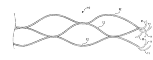
- An example of the tether 10 knitted in a net shape is shown in FIG.
- the tether 10 forms a network by connecting three spun yarns 12 to adjacent spun yarns 12 at predetermined intervals or random intervals.
- Reference numeral 11 indicates a small thread.
- the tether 10 by manufacturing the tether 10 with the spun yarn 12 made of CNT, it is possible to realize a tether that is lightweight and has good electronic collection performance. Further, in the unlikely event that the tether 10 stays in the orbit for a long time such as in the event of a failure, the CNT deteriorates due to the orbital environment such as atomic oxygen, so that the tether 10 can be made to disappear after a certain period of time. Therefore, it is possible to relax the reliability requirement so that the deorbit does not fail after the mission is completed.
- the tether 10 may be intentionally used with CNTs that originally have many defects, or may be damaged by chemicals, a laser, or the like after the tether body is manufactured. If the tether 10 has a relatively short mission period, the life of the tether 10 in orbit can be shortened, and the burden of avoiding collision with an operating satellite and the risk of collision can be further reduced.
- the surface of the tether body may be coated with a film resistant to atomic oxygen.
- a film resistant to atomic oxygen By allowing the tether body to disappear due to atomic oxygen after the coated film disappears due to another factor such as heat or ultraviolet rays, for example, the life of the tether 10 in orbit can be extended.
- the tether 10 may be formed by collecting fine spun yarns in a fur shape. As a result, the natural extinction effect of the tether 10 due to the collision of atomic oxygen can be enhanced, and the electron collecting ability from the space plasma is also enhanced, so that the current flowing through the tether 10 can be increased and the orbital descent force can be enhanced. ..
- the surface of the tether 10 may be subjected to a treatment such as raising to enhance the electron emission effect. As a result, more electrons can be emitted from the surface of the tether 10, the current flowing through the tether 10 can be increased, and the orbital descent force can be increased.
- a large current is intentionally passed through the tether 10 to raise the temperature of the tether 10 made of CNT by Joule heating, thereby promoting material deterioration due to atomic oxygen and shortening the life of the tether 10 in orbit.
- This makes it possible to further reduce the burden of avoiding collisions with operational satellites and the risk of collisions.
- the mission period of the tether 10 does not have to be short.
- the means for passing a large current through the tether 10 may be provided in, for example, the spacecraft 20.
- FIG. 3 is a diagram showing a configuration of a debris removal system according to another embodiment.
- a very small part region 111 in the length direction of the tether 110 is CNT. It is constructed by knitting a spun yarn made of, for example, in a net shape or a ribbon shape. This region 111 is provided at a position close to the spacecraft 20. Most regions 112 other than region 111 are constructed by knitting ordinary tether materials such as aluminum wire and stainless steel fibers.
- the spacecraft 20 has a shutter member 121 for preventing collision of atomic oxygen with the region 111.
- the shutter member 121 can be opened and closed. When the shutter member 121 is closed, the passage of atomic oxygen to the region 111 is restricted, and when the shutter member 121 is opened, the atomic oxygen passes through the region 111.
- the opening and closing of the shutter member 121 may be controlled according to a predetermined sequence, for example, by a timer, or by an operation from the ground side or the like.
- the life of the tether 110 can be freely controlled according to the mission period by closing the shutter member 121 during the mission and opening the shutter member 121 just before the end of the mission.
- the region 111 may have a defect or damage, may be coated with an atomic oxygen resistant coating, and further. Other configurations may be adopted. Further, the debris removal system 100 does not have to have the shutter member 121.
- the spun yarn by lashing with a spun yarn made of CNT, if the spacecraft breaks down during the mission, the spun yarn that is released from the lashing after a certain period of time is automatically bound by a spring or the like.
- the spun yarn may function as a conductive tether by being configured to be stretched. This allows the spacecraft to then automatically descend into orbit.
- the present invention can be applied to applications other than tethers.
- a large space structure such as a space elevator is damaged and generates fragments
- fragments can be formed by making a part of the large space structure that can become such fragments a member made of CNT. It will soon disappear and will not orbit in outer space for a long period of time.
- CNTs are used as a conductive member that collapses or disappears due to exposure to atomic oxygen
- the member is a nanocarbon material made of SP2-bonded carbon.
- CNTs for example, graphene, carbon nanofivers or carbon nanocoils can be used.
Landscapes
- Engineering & Computer Science (AREA)
- Chemical & Material Sciences (AREA)
- Organic Chemistry (AREA)
- Manufacturing & Machinery (AREA)
- Textile Engineering (AREA)
- Materials Engineering (AREA)
- Nanotechnology (AREA)
- Inorganic Chemistry (AREA)
- Remote Sensing (AREA)
- Aviation & Aerospace Engineering (AREA)
- Carbon And Carbon Compounds (AREA)
- Braiding, Manufacturing Of Bobbin-Net Or Lace, And Manufacturing Of Nets By Knotting (AREA)
- Woven Fabrics (AREA)
Abstract
【課題】運用衛星などへ衝突回避の負担や衝突のリスクをより低減することができるテザー及び人工天体を提供すること。 【解決手段】テザー10は、長さ方向の少なくとも一部の領域が、原子状酸素の暴露によって崩壊又は消失する部材からなる。例えば、テザー10は、カーボンナノチューブからなる紡績糸を網状やリボン状に編んで構成される。
Description
本発明は、例えば宇宙空間のデブリを除去するために用いられるテザー及び人工天体に関する。
数百m~数十kmの長さのテザーが宇宙空間で実証されている。テザーは、巻き取られた状態で宇宙空間に打ち上げられ、テザーの一端に取り付けられたエンドマスをバネなどで秒速数m/sで放出することなどで伸展される(非特許文献1参照)。本発明者らは、軽量、省占有面積、かつ、高強度の宇宙用のテザーを提案した(特許文献1参照)。
テザーのうち導電性テザーは、誘導起電力または外部電源により電流を流しながら地磁場との相互作用によって推力(ローレンツ力)を発生させるもので、低コスト化が可能であることから有望視されている。導電性テザーは、数ヶ月から1年程度の運用でデブリの軌道高度を降下させ、デブリを除去することができると期待されていた。
http://www.kenkai.jaxa.jp/research/debris/deb-edt.html
しかし、この種のテザーが切断したり、テザーを運用していたテザー端の宇宙機が故障して、テザー衛星の推進力や衝突回避能力が失われた場合などに、テザーが伸展した状態で長期間宇宙空間の軌道上を周回することになり、運用衛星などに衝突回避の負担を与えたり、衝突のリスクを与えていた。
そこで、本発明者らは、張力解放時にキンクして自律的に変形する、すなわち張力が失われると集束するテザーに関する技術を提案した。
この技術によれば、テザーが長期間宇宙空間の軌道上を周回することになっても、長いテザーが集束した状態となって運用衛星などへの衝突回避の負担や衝突のリスクを低減することができる。
本発明の目的は、運用衛星などへの衝突回避の負担や衝突のリスクをより低減することができるテザー及び人工天体を提供することにある。
上記目的を達成するため、本発明の一形態に係るテザーは、長さ方向の少なくとも一部の領域が、原子状酸素の暴露によって崩壊又は消失する部材からなる。典型的には、テザー全体が前記部材からなる。或いは、テザーの長さ方向の一部の領域が前記部材からなる。前記部材からなる領域は、典型的には、宇宙機に近い位置である。また、前記部材は、典型的には、導電性を有する。
テザーは、宇宙空間では原子状酸素と軌道速度で衝突する。原子状酸素の暴露によって崩壊又は消失し、かつ、導電性の部材からなる領域は、それまではテザーの一部又は全部を構成し、テザーとしての機能を発揮しているが、原子状酸素の暴露によって例えばガス化して消失していくため、テザーの切断時や故障時等、テザーが宇宙空間に数百m~数十kmの長さで展開して残存している場合でも、やがて消失していき、或いは、分解して細かい破片となって大気抵抗の影響を受けて早く軌道から落下し、或いは、エンドマス等とともに軌道から下降していき、宇宙空間に残らないようにすることができる。これにより、運用衛星などへの衝突回避の負担や衝突のリスクをより低減することができる。
前記部材は、SP2結合の炭素からなるナノカーボン材料からなることが好ましい。前記SP2結合の炭素からなるナノカーボン材料としては、カーボンナノチューブ、グラフィン、カーボンナノフィバー又はカーボンナノコイルが好適である。
前記部材は、欠損又はダメージを有してもよい。この場合、元々欠損の多い部材を使用してもよい。ここで、欠損とは、テザーを構成する紡績糸や小糸に対するマクロな損傷でも良いし、あるいは、ナノカーボン材料の結晶構造自体のナノレベルの損傷でも良い。また、テザー本体の製作後に、薬品やレーザーなどでダメージを与えてもよい。欠損やダメージを有する部材を用いることで、軌道上でのテザーの寿命をコントロールすることができる。
前記部材の表面は、原子状酸素耐性のある皮膜がコーティングされてもよい。原子状酸素耐性のあるコーティング材としては、例えば金属やシリコーン等を用いることができる。コーティングされた皮膜が熱や紫外線等の別の要因で消失した後に、前記部材が原子状酸素により消失するようにすることで、軌道上でのテザーの寿命をコントロールすることができる。
前記部材は、原子状酸素の暴露によって崩壊又は消失し、かつ、導電性の紡績糸から構成されてもよい。部材を紡績糸により構成することで、例えば網状やリボン状に編むことができる。また、十分な導電性を確保することも可能となり、かつ、密度も低いため、重量に対する性能の高いテザーを構成できる。また、密度が低いため、万が一他の物体に衝突した場合でも相手に与えるダメージを小さくできる。
ここで、前記部材は、細い紡績糸をいわばファー状に集めて構成してもよい。このような構成とすることで、典型的には、原子状酸素の衝突によるテザーの自然消滅効果を高めることができる。同時に、宇宙プラズマからの電子収集能力も高まるため、テザーに流れる電流が増加し、軌道降下力を高めることができる。
また、前記部材の表面に電子放出効果を高めるような起毛等の処理を施してもよい。これにより、前記部材の表面からより多くの電子を放出させて、テザーに流れる電流を増やし、軌道降下力を高めることができる。
本発明の一形態に係る人工天体は、宇宙空間の軌道上を周回する人工天体であって、損傷を受け破片となった場合に宇宙空間に残存が問題となる部位を、原子状酸素の暴露によって崩壊又は消失する部材からなる構成したものである。前記部材は、典型的には、導電性を有する。
本発明により、運用衛星などへの衝突回避の負担や衝突のリスクをより低減することができる。
以下、図面を参照しながら、本発明の実施形態を説明する。
図1は、本発明の一実施形態に係るデブリ除去システムの構成を示す図である。
図1に示すように、デブリ除去システム1は、宇宙用のテザー10と、テザー10を収容するテザー収容装置を搭載する宇宙機20と、テザー10の一端に取り付けられたエンドマス30とを有する。エンドマス30側には、電子放出源が設けられている。電子放出源については、例えば非特許文献1に記載されている。図1では、宇宙機20がデブリ2に取り付けられた状態を示した。
図1は、本発明の一実施形態に係るデブリ除去システムの構成を示す図である。
図1に示すように、デブリ除去システム1は、宇宙用のテザー10と、テザー10を収容するテザー収容装置を搭載する宇宙機20と、テザー10の一端に取り付けられたエンドマス30とを有する。エンドマス30側には、電子放出源が設けられている。電子放出源については、例えば非特許文献1に記載されている。図1では、宇宙機20がデブリ2に取り付けられた状態を示した。
テザー10は、カーボンナノチューブ(以下、これを「CNT」と呼ぶ。)からなる紡績糸を例えば網状やリボン状に編んで構成される。網状に編んだテザー10の一例を図2に示す。テザー10は、3本の紡績糸12がそれぞれ隣接する紡績糸12と所定の間隔或いはランダム間隔で結ぶことで網状を構成している。符号11は小糸を示している。網状とすることで、微小デブリが衝突しても切断されにくくすることができるが、本発明に係るテザーは、このような網状の構成に限定されるものではない。
本実施形態では、テザー10をCNTからなる紡績糸12で製作することにより、軽量で電子収集性能のよいテザーを実現できる。また、万が一故障時等、テザー10が軌道上に長時間留まってしまう場合には、原子状酸素等の軌道上の環境によってCNTは劣化するため一定期間後に消失するようにできる。従って、ミッション終了後にデオービットに失敗しないようにする信頼性要求等を緩和できる。
なお、テザー10は、元々欠損の多いCNTをあえて使用してもよく、またテザー本体の製作後に、薬品やレーザーなどでダメージを与えてもよい。ミッション期間の比較的短いテザー10であれば、軌道上でのテザー10の寿命をより短くすることができ、運用衛星などへの衝突回避の負担や衝突のリスクをさらに低減することができる。
また、テザー本体の表面に、原子状酸素耐性のある皮膜をコーティングしてもよい。コーティングされた皮膜が熱や紫外線等の別の要因で消失した後に、テザー本体が原子状酸素により消失するようにすることで、例えば軌道上でのテザー10の寿命を長くすることができる。
さらに、テザー10は、細い紡績糸をファー状に集めて構成してもよい。これにより、原子状酸素の衝突によるテザー10の自然消滅効果を高めることができ、また宇宙プラズマからの電子収集能力も高まるため、テザー10に流れる電流が増加し、軌道降下力を高めることができる。
また、テザー10の表面に電子放出効果を高めるような起毛等の処理を施してもよい。これにより、テザー10の表面からより多くの電子を放出させて、テザー10に流れる電流を増やし、軌道降下力を高めることができる。
さらに、ミッション終了間際に、テザー10にあえて大きな電流を流してジュール加熱によりCNTからなるテザー10を高温化することで原子状酸素による材料劣化を促し、軌道上でのテザー10の寿命をより短くすることができ、運用衛星などへの衝突回避の負担や衝突のリスクをさらに低減することができる。この場合に、テザー10のミッション期間は短くなくてもよい。また、テザー10に大きな電流を流す手段は、例えば宇宙機20に設ければよい。
次に、本発明の他の実施形態を説明する。
図3は、他の実施形態に係るデブリ除去システムの構成を示す図であり、同図に示すデブリ除去システム100では、テザー110の長さ方向の例えばごく僅かな一部の領域111が、CNTからなる紡績糸を例えば網状やリボン状に編んで構成される。この領域111は、宇宙機20に近い位置に設けられている。領域111以外の大半の領域112は、通常のテザーの材料、例えばアルミニウムワイヤとステンレス繊維とを編んで構成される。
図3は、他の実施形態に係るデブリ除去システムの構成を示す図であり、同図に示すデブリ除去システム100では、テザー110の長さ方向の例えばごく僅かな一部の領域111が、CNTからなる紡績糸を例えば網状やリボン状に編んで構成される。この領域111は、宇宙機20に近い位置に設けられている。領域111以外の大半の領域112は、通常のテザーの材料、例えばアルミニウムワイヤとステンレス繊維とを編んで構成される。
宇宙機20は、領域111への原子状酸素の衝突を防ぐためのシャッター部材121を有する。このシャッター部材121は、開閉が可能であり、シャッター部材121を閉じると原子状酸素の領域111への通過を規制し、シャッター部材121を開くと原子状酸素が領域111を通過する。シャッター部材121の開閉の制御は、例えば所定のシーケンスに従って行ってもよいし、タイマーによって行ってもよいし、地上側等からの操作によって行ってもよい。
このデブリ除去システム100では、ミッション中はシャッター部材121を閉じておき、ミッション終了間際にシャッター部材121を開くことで、テザー110の寿命をミッション期間に合致させて自在にコントロールすることができる。
なお、この実施形態におけるテザー110では、最初に示した実施形態と同様に、領域111は、欠損又はダメージを有していてもよく、原子状酸素耐性のあるコーティングがされていてもよく、さらにその他の構成を採用してもよい。また、このデブリ除去システム100は、シャッター部材121を持たなくてもよい。
なお、この実施形態におけるテザー110では、最初に示した実施形態と同様に、領域111は、欠損又はダメージを有していてもよく、原子状酸素耐性のあるコーティングがされていてもよく、さらにその他の構成を採用してもよい。また、このデブリ除去システム100は、シャッター部材121を持たなくてもよい。
また、さらに別の実施形態として、CNTからなる紡績糸で固縛しておくことにより、宇宙機がミッション中に故障した場合には、一定時間後に固縛から外れた紡績糸をバネ等で自動的に伸展するように構成することで、紡績糸を導電性テザーとして機能させるようにしてもよい。これにより、宇宙機は、その後、自動的に軌道を降下できる。
さらに、本発明は、テザー以外の用途にも適用できる。
例えば、宇宙用エレベータ等、大型宇宙構造が万が一損傷を受けて破片を発生させた場合でも、大型宇宙構造のうちそのような破片となり得る部位をCNTからなる部材とすることで、そのような破片はやがて消失し、長期間宇宙空間の軌道上を周回するようなことはなくなる。
例えば、宇宙用エレベータ等、大型宇宙構造が万が一損傷を受けて破片を発生させた場合でも、大型宇宙構造のうちそのような破片となり得る部位をCNTからなる部材とすることで、そのような破片はやがて消失し、長期間宇宙空間の軌道上を周回するようなことはなくなる。
以上の実施形態では、原子状酸素の暴露によって崩壊又は消失し、かつ、導電性の部材としてCNTを用いた例を説明したが、当該部材は、SP2結合の炭素からなるナノカーボン材料であればよく、CNT以外に例えばグラフィン、カーボンナノフィバー又はカーボンナノコイルを用いることができる。
10、110 :テザー
12 :紡績糸
111 :領域
12 :紡績糸
111 :領域
Claims (11)
- 長さ方向の少なくとも一部の領域が、原子状酸素の暴露によって崩壊又は消失する部材からなるテザー。
- 前記部材は、SP2結合の炭素からなるナノカーボン材料からなる、請求項1に記載のテザー。
- 前記SP2結合の炭素からなるナノカーボン材料は、カーボンナノチューブ、グラフィン、カーボンナノフィバー又はカーボンナノコイルである、請求項2に記載のテザー。
- 前記部材は、欠損又はダメージを有する、請求項1乃至3のいずれかに記載のテザー。
- 前記部材の表面は、原子状酸素耐性のある皮膜がコーティングされている、請求項1乃至4のいずれかに記載のテザー。
- 前記部材は、原子状酸素の暴露によって崩壊又は消失し、かつ、導電性の紡績糸から構成される、請求項1乃至5のいずれかに記載のテザー。
- 前記部材は、前記紡績糸を編んで構成される、請求項6に記載のテザー。
- 前記部材は、細い前記紡績糸をファー状に集めて構成される、請求項6に記載のテザー。
- 前記紡績糸の表面は、電子放出効果を高める処理が施されている、請求項6乃至8のいずれかに記載のテザー。
- 前記電子放出効果を高める処理は、起毛処理である、請求項9に記載のテザー。
- 宇宙空間の軌道上を周回する人工天体であって、
損傷を受け破片となった場合に宇宙空間に残存が問題となる部位を、原子状酸素の暴露によって崩壊又は消失する部材からなる構成した
人工天体。
Applications Claiming Priority (2)
| Application Number | Priority Date | Filing Date | Title |
|---|---|---|---|
| JP2019-072824 | 2019-04-05 | ||
| JP2019072824A JP2020168995A (ja) | 2019-04-05 | 2019-04-05 | テザー及び人工天体 |
Publications (1)
| Publication Number | Publication Date |
|---|---|
| WO2020204080A1 true WO2020204080A1 (ja) | 2020-10-08 |
Family
ID=72668966
Family Applications (1)
| Application Number | Title | Priority Date | Filing Date |
|---|---|---|---|
| PCT/JP2020/015045 Ceased WO2020204080A1 (ja) | 2019-04-05 | 2020-04-01 | テザー及び人工天体 |
Country Status (2)
| Country | Link |
|---|---|
| JP (1) | JP2020168995A (ja) |
| WO (1) | WO2020204080A1 (ja) |
Families Citing this family (1)
| Publication number | Priority date | Publication date | Assignee | Title |
|---|---|---|---|---|
| EP4682063A1 (en) * | 2023-03-17 | 2026-01-21 | Carbon Fly, Inc. | Ribbon, tether material, tether, method for manufacturing ribbon, method for manufacturing tether material, and method for manufacturing tether |
Citations (8)
| Publication number | Priority date | Publication date | Assignee | Title |
|---|---|---|---|---|
| US6419191B1 (en) * | 1997-09-12 | 2002-07-16 | Robert P. Hoyt | Electrodynamic tether control |
| US6431497B1 (en) * | 2000-09-08 | 2002-08-13 | Robert P. Hoyt | Failure resistant multiline tether |
| US20040149485A1 (en) * | 2002-08-08 | 2004-08-05 | Edwards Bradley C | Cable for a space elevator |
| US7118074B1 (en) * | 2003-10-17 | 2006-10-10 | The United States Of America As Represented By The Administrator Of The National Aeronautics And Space Administration | Electrodynamic tether |
| JP2007131124A (ja) * | 2005-11-10 | 2007-05-31 | Japan Aerospace Exploration Agency | 宇宙用テザー |
| JP2016002813A (ja) * | 2014-06-13 | 2016-01-12 | 国立研究開発法人宇宙航空研究開発機構 | スペースデブリの軌道降下方法、軌道降下システム、及び、人工衛星の軌道変換方法、軌道変換システム |
| EP3375714A1 (en) * | 2015-11-13 | 2018-09-19 | Universidad Carlos III de Madrid | System for in-orbit propulsion via floating conductor cables |
| JP2019090146A (ja) * | 2017-11-13 | 2019-06-13 | 国立研究開発法人宇宙航空研究開発機構 | 網、テザー収容装置及び網の製造方法 |
-
2019
- 2019-04-05 JP JP2019072824A patent/JP2020168995A/ja active Pending
-
2020
- 2020-04-01 WO PCT/JP2020/015045 patent/WO2020204080A1/ja not_active Ceased
Patent Citations (8)
| Publication number | Priority date | Publication date | Assignee | Title |
|---|---|---|---|---|
| US6419191B1 (en) * | 1997-09-12 | 2002-07-16 | Robert P. Hoyt | Electrodynamic tether control |
| US6431497B1 (en) * | 2000-09-08 | 2002-08-13 | Robert P. Hoyt | Failure resistant multiline tether |
| US20040149485A1 (en) * | 2002-08-08 | 2004-08-05 | Edwards Bradley C | Cable for a space elevator |
| US7118074B1 (en) * | 2003-10-17 | 2006-10-10 | The United States Of America As Represented By The Administrator Of The National Aeronautics And Space Administration | Electrodynamic tether |
| JP2007131124A (ja) * | 2005-11-10 | 2007-05-31 | Japan Aerospace Exploration Agency | 宇宙用テザー |
| JP2016002813A (ja) * | 2014-06-13 | 2016-01-12 | 国立研究開発法人宇宙航空研究開発機構 | スペースデブリの軌道降下方法、軌道降下システム、及び、人工衛星の軌道変換方法、軌道変換システム |
| EP3375714A1 (en) * | 2015-11-13 | 2018-09-19 | Universidad Carlos III de Madrid | System for in-orbit propulsion via floating conductor cables |
| JP2019090146A (ja) * | 2017-11-13 | 2019-06-13 | 国立研究開発法人宇宙航空研究開発機構 | 網、テザー収容装置及び網の製造方法 |
Also Published As
| Publication number | Publication date |
|---|---|
| JP2020168995A (ja) | 2020-10-15 |
Similar Documents
| Publication | Publication Date | Title |
|---|---|---|
| EP3712312B1 (en) | Net, tether accommodating device, and method for producing net | |
| DE202020005922U1 (de) | NV-Zentren basierender Quantencomputer mit einer Steuervorrichtung und Elektron-Elektron-Kopplung zwischen Quantenpunkten | |
| WO2020204080A1 (ja) | テザー及び人工天体 | |
| JP5139457B2 (ja) | カーボンナノチューブ構造体の製造方法 | |
| US8229074B2 (en) | Carbon nanotube array for focused field emission | |
| Banhart | Irradiation of carbon nanotubes with a focused electron beam in the electron microscope | |
| US6431497B1 (en) | Failure resistant multiline tether | |
| Gasdaska et al. | Testing of carbon nanotube field emission cathodes | |
| EP2834831B1 (de) | Röntgenstrahlungsquelle, verfahren zum erzeugen von röntgenstrahlung sowie verwendung einer monochromatische röntgenstrahlung aussendenden röntgenstrahlungsquelle | |
| Ohkawa et al. | Field emission cathodes for an electrodynamic tether experiment on the H-II transfer vehicle | |
| Kemnitz et al. | Characterization of simulated low earth orbit space environment effects on acid-spun carbon nanotube yarns | |
| US11476075B2 (en) | Electron source and electron source unit | |
| JP4543203B2 (ja) | 宇宙用テザー | |
| Zieliński | Dark-bright excitons mixing in alloyed InGaAs self-assembled quantum dots | |
| Biryukov et al. | Channeling technique to make nanoscale ion beams | |
| JP7432187B2 (ja) | スペースデブリ除去装置 | |
| DE102011007828A1 (de) | Füllgase mit optischer Wirkung für EUV-Lithographieanlagen | |
| JP4538591B2 (ja) | 電子放出装置 | |
| Ohkawa et al. | Research and Development of Electrodynamic Tethers for Space Debris Mitigation | |
| WO2019093520A1 (ja) | 網、テザー収容装置及び網の製造方法 | |
| US20260018364A1 (en) | X-ray tube with field effect emitter | |
| Guo et al. | Spontaneously formed closed rings of single-wall carbon nanotube bundles and their physical mechanism | |
| DE102008026633A1 (de) | Röntgenröhre | |
| DE102022103408A1 (de) | Elektronenemitter für Raumfahrtanwendungen | |
| JP2005326299A (ja) | 低速陽電子生成のための減速材およびその製造方法 |
Legal Events
| Date | Code | Title | Description |
|---|---|---|---|
| 121 | Ep: the epo has been informed by wipo that ep was designated in this application |
Ref document number: 20784573 Country of ref document: EP Kind code of ref document: A1 |
|
| NENP | Non-entry into the national phase |
Ref country code: DE |
|
| 122 | Ep: pct application non-entry in european phase |
Ref document number: 20784573 Country of ref document: EP Kind code of ref document: A1 |