WO2020203565A1 - 水中ビークル用冷却システム - Google Patents
水中ビークル用冷却システム Download PDFInfo
- Publication number
- WO2020203565A1 WO2020203565A1 PCT/JP2020/013377 JP2020013377W WO2020203565A1 WO 2020203565 A1 WO2020203565 A1 WO 2020203565A1 JP 2020013377 W JP2020013377 W JP 2020013377W WO 2020203565 A1 WO2020203565 A1 WO 2020203565A1
- Authority
- WO
- WIPO (PCT)
- Prior art keywords
- refrigerant
- heat exchanger
- tank
- cooling system
- circulation path
- Prior art date
- Legal status (The legal status is an assumption and is not a legal conclusion. Google has not performed a legal analysis and makes no representation as to the accuracy of the status listed.)
- Ceased
Links
Images
Classifications
-
- B—PERFORMING OPERATIONS; TRANSPORTING
- B60—VEHICLES IN GENERAL
- B60H—ARRANGEMENTS OF HEATING, COOLING, VENTILATING OR OTHER AIR-TREATING DEVICES SPECIALLY ADAPTED FOR PASSENGER OR GOODS SPACES OF VEHICLES
- B60H1/00—Heating, cooling or ventilating devices
- B60H1/22—Heating, cooling or ventilating devices the heat source being other than the propulsion plant
-
- B—PERFORMING OPERATIONS; TRANSPORTING
- B63—SHIPS OR OTHER WATERBORNE VESSELS; RELATED EQUIPMENT
- B63C—LAUNCHING, HAULING-OUT, OR DRY-DOCKING OF VESSELS; LIFE-SAVING IN WATER; EQUIPMENT FOR DWELLING OR WORKING UNDER WATER; MEANS FOR SALVAGING OR SEARCHING FOR UNDERWATER OBJECTS
- B63C11/00—Equipment for dwelling or working underwater; Means for searching for underwater objects
- B63C11/48—Means for searching for underwater objects
-
- B—PERFORMING OPERATIONS; TRANSPORTING
- B63—SHIPS OR OTHER WATERBORNE VESSELS; RELATED EQUIPMENT
- B63G—OFFENSIVE OR DEFENSIVE ARRANGEMENTS ON VESSELS; MINE-LAYING; MINE-SWEEPING; SUBMARINES; AIRCRAFT CARRIERS
- B63G8/00—Underwater vessels, e.g. submarines; Equipment specially adapted therefor
- B63G8/36—Adaptations of ventilation, e.g. schnorkels, cooling, heating, or air-conditioning
-
- B—PERFORMING OPERATIONS; TRANSPORTING
- B63—SHIPS OR OTHER WATERBORNE VESSELS; RELATED EQUIPMENT
- B63J—AUXILIARIES ON VESSELS
- B63J2/00—Arrangements of ventilation, heating, cooling, or air-conditioning
- B63J2/12—Heating; Cooling
-
- F—MECHANICAL ENGINEERING; LIGHTING; HEATING; WEAPONS; BLASTING
- F25—REFRIGERATION OR COOLING; COMBINED HEATING AND REFRIGERATION SYSTEMS; HEAT PUMP SYSTEMS; MANUFACTURE OR STORAGE OF ICE; LIQUEFACTION SOLIDIFICATION OF GASES
- F25D—REFRIGERATORS; COLD ROOMS; ICE-BOXES; COOLING OR FREEZING APPARATUS NOT OTHERWISE PROVIDED FOR
- F25D11/00—Self-contained movable devices, e.g. domestic refrigerators
-
- F—MECHANICAL ENGINEERING; LIGHTING; HEATING; WEAPONS; BLASTING
- F25—REFRIGERATION OR COOLING; COMBINED HEATING AND REFRIGERATION SYSTEMS; HEAT PUMP SYSTEMS; MANUFACTURE OR STORAGE OF ICE; LIQUEFACTION SOLIDIFICATION OF GASES
- F25D—REFRIGERATORS; COLD ROOMS; ICE-BOXES; COOLING OR FREEZING APPARATUS NOT OTHERWISE PROVIDED FOR
- F25D13/00—Stationary devices, e.g. cold-rooms
-
- F—MECHANICAL ENGINEERING; LIGHTING; HEATING; WEAPONS; BLASTING
- F25—REFRIGERATION OR COOLING; COMBINED HEATING AND REFRIGERATION SYSTEMS; HEAT PUMP SYSTEMS; MANUFACTURE OR STORAGE OF ICE; LIQUEFACTION SOLIDIFICATION OF GASES
- F25D—REFRIGERATORS; COLD ROOMS; ICE-BOXES; COOLING OR FREEZING APPARATUS NOT OTHERWISE PROVIDED FOR
- F25D9/00—Devices not associated with refrigerating machinery and not covered by groups F25D1/00 - F25D7/00; Combinations of devices covered by two or more of the groups F25D1/00 - F25D7/00
Definitions
- the present invention relates to a cooling system mounted on an underwater vehicle.
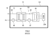
- FIG. 3 is a block diagram showing an example of a conventional cooling system 102 mounted on the underwater vehicle 101.
- the conventional underwater vehicle 101 has a refrigerator 81 that uses seawater and an FCU85 (fan coil unit) that sends out cold air using cold water generated by the refrigerator 81 inside the pressure hull 10.
- the heating element 20A arranged inside the pressure hull 10 is air-cooled by the cold air sent from the FCU 85.
- the refrigerator 81 has a seawater flow path 82, a chilled water circuit 84, and a refrigerating circuit 83 that mediates heat exchange between the seawater flow path 82 and the chilled water circuit 84.
- Patent Document 1 discloses a submarine provided with a refrigerating device that uses seawater as described above.
- the refrigeration system includes a refrigeration circuit including a condenser located inside the hull shell, and a closed circulation path including a water lid of the condenser and a cooler located outside the hull shell.
- the cooling fluid that circulates in the closed circulation path by natural circulation or forced circulation is cooled by seawater in the cooler and exchanges heat with the refrigerant that circulates in the refrigeration circuit at the lid of the condenser.
- the condenser is indirectly cooled by seawater.
- the heat load inside the underwater vehicle will increase as the performance of electronic devices (for example, batteries, inverters, servers, etc.) mounted on the underwater vehicle increases.
- electronic devices for example, batteries, inverters, servers, etc.
- the size of the seawater pump 86 that sends seawater to the refrigerator 81, the size of the cold water pump 87 that sends cold water to the FCU85, and the size of the cold water pump 87 are increased. Due to the increase in size of the blower of FCU85, the size of the entire system and the increase in energy consumption are accompanied.
- the present invention has been made in view of the above circumstances, and an object of the present invention is to propose a technique for improving the cooling capacity of a cooling system mounted on an underwater vehicle while suppressing an increase in the size of the system. ..
- the cooling system for an underwater vehicle is A liquid immersion tank arranged inside the pressure-resistant shell of the submersible vehicle, an external heat exchanger arranged outside the pressure-resistant shell, an outward pipe connecting the tank outlet of the liquid immersion tank and the inlet of the external heat exchanger, A closed refrigerant circulation path having a return pipe connecting the outlet of the external heat exchanger and the tank inlet of the immersion tank is provided, and the heating element is immersed in the refrigerant in the immersion tank to obtain the external heat.
- the heating element is cooled by heat exchange between the refrigerant and the water around the pressure-resistant shell in the exchanger.
- the heating element is cooled by the liquid permeation liquid cooling method, and the refrigerant directly exchanges heat with the water around the pressure hull. Since the liquid phase refrigerant comes into direct contact with the heating element to remove heat, the cooling capacity is significantly improved as compared with the conventional air cooling method. Further, by improving the cooling capacity, the installation density of the heating element can be increased, and the increase in size of the system can be suppressed.
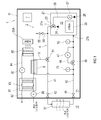
- FIG. 1 is a block diagram showing an overall configuration of a cooling system mounted on an underwater vehicle according to an embodiment of the present invention.
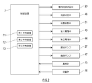
- FIG. 2 is a diagram showing a configuration of a control system of a cooling system.
- FIG. 3 is a block diagram showing the overall configuration of a cooling system mounted on a conventional underwater vehicle.
- FIG. 1 is a block diagram showing an overall configuration of a cooling system 2 mounted on an underwater vehicle 1 according to an embodiment of the present invention.
- the underwater vehicle 1 shown in FIG. 1 has a pressure hull 10 for navigating underwater and on water and withstanding water pressure.
- the inside of the pressure hull 10 is referred to as “inside the vehicle 11”, and the outside of the pressure hull 10 is referred to as “outside the vehicle 12”.
- the pressure-resistant shell 10 is composed of two layers, an outer shell having a non-pressure-resistant structure and an inner shell having a pressure-resistant structure, the inside 11 of the vehicle represents the inside of the inner shell, and the outer 12 of the vehicle represents the outside of the inner shell (inner shell). (Including between and the outer shell).
- the cooling system 2 mounted on the underwater vehicle 1 includes an immersion tank 21 provided in the vehicle 11.
- the immersion tank 21 is filled with the refrigerant 22.
- the refrigerant in the immersion tank 21 is a liquid phase in the lower part of the tank and a gas-liquid two-phase (or gas phase) in the upper part of the tank.
- the entire heating element 20 is submerged in the liquid phase refrigerant 22.
- an inert liquid that can be operated by immersing an electronic device including a power source is used.
- An external heat exchanger 31 is provided on the outside of the vehicle 12.
- the tank outlet 21a provided at the top of the immersion tank 21 and the inlet of the external heat exchanger 31 are connected by an outward pipe 41.
- the tank inlet 21b provided at the bottom of the immersion tank 21 and the outlet of the external heat exchanger 31 are connected by a return pipe 42.
- the outward pipe 41 is above the return pipe 42. To position.
- a sealed refrigerant circulation path 4 including the immersion tank 21 and the external heat exchanger 31 is formed.
- the inside of the refrigerant circulation path 4 is at atmospheric pressure or is depressurized more than atmospheric pressure.
- the degree of vacuum in the refrigerant circulation path 4 may be adjusted so that the phase change of the refrigerant 22 occurs in the refrigerant system.
- the external heat exchanger 31 cools the refrigerant 22 by exchanging heat between the water around the pressure hull 10 and the refrigerant 22 flowing through the refrigerant circulation path 4.
- the underwater vehicle 1 sails in the sea, and the water around the pressure hull 10 is seawater.
- the water around the pressure hull 10 is fresh water.
- An in-tank flow path switching valve 23 is provided at the tank outlet 21a of the immersion tank 21.
- An upper outlet 24, which is an outlet for a gas-liquid two-phase or gas-phase refrigerant 22, is provided in the upper part of the immersion tank 21.
- the upper outlet 24 is connected to the in-tank flow path switching valve 23 via a pipe or the like.
- a lower outlet 25, which is an outlet of the liquid phase refrigerant 22, is provided in the lower portion of the immersion tank 21.
- the lower outlet 25 and the in-tank flow path switching valve 23 are connected by a pumping pipe 26, and the pumping pipe 26 is provided with a pumping pump 27 for pumping the refrigerant 22.
- the in-tank flow path switching valve 23 has a first state in which the tank outlet 21a and the upper outlet 24 are connected, and the tank outlet 21a and the lower outlet 25. Selectively switches between the second state to which is connected.
- a first on-off valve 43 is provided immediately upstream of the external heat exchanger 31.
- a second on-off valve 44 is provided immediately downstream of the external heat exchanger 31.
- the refrigerant 22 flows to the external heat exchanger 31.
- the first on-off valve 43 and the second on-off valve 44 are closed, the refrigerant 22 does not flow to the external heat exchanger 31.
- the first on-off valve 43 and the second on-off valve 44 switch the opening and closing of the valves under the control of the control device 7.
- a fire extinguishing flow path 55 is connected to the outbound pipe 41.
- the fire extinguishing flow path 55 is provided with a fire extinguishing on-off valve 56.
- the fire extinguishing on-off valve 56 is opened, the refrigerant 22 is sent to the fire site, and the refrigerant 22 is used for extinguishing the fire.
- the upstream end and the downstream end of the forced circulation path 48 are connected to the downstream side of the connection portion of the return pipe 42 with the internal heat exchange path 5.
- the forced circulation path 48 is provided with a refrigerant pump 47 that pumps the refrigerant 22.
- a flow path switching valve 46 is provided at the connection portion between the return pipe 42 and the upstream end of the forced circulation path 48. Under the control of the control device 7, the flow path switching valve 46 flows the refrigerant 22 flowing through the return pipe 42 into the forced circulation path 48 in the first state in which the refrigerant 22 flowing through the return pipe 42 does not flow into the forced circulation path 48. Selectively switch to the second state.
- the flow path switching valve 46 By switching the flow path switching valve 46, the refrigerant 22 flowing through the refrigerant circulation path 4 passes through the forced circulation path 48, and the refrigerant 22 flowing through the refrigerant circulation path 4 does not pass through the forced circulation path 48. Is switched.
- the refrigerant circulation path 4 is connected to an internal heat exchange path 5 that allows the refrigerant 22 flowing through the outward path pipe 41 to flow to the return path pipe 42 without passing through the external heat exchanger 31.
- the upstream end of the internal heat exchange path 5 is connected to the outward pipe 41, and the downstream end of the internal heat exchange path 5 is connected to the return pipe 42.
- a flow rate adjusting valve 51 is provided at a connection portion between the upstream end of the internal heat exchange path 5 and the outward path pipe 41. The flow rate adjusting valve 51 adjusts the flow rate of the refrigerant flowing to the internal heat exchange path 5 by changing the opening degree in the range of 0 to 100% under the control of the control device 7.
- An internal heat exchanger 6 is provided in the internal heat exchange path 5.
- the internal heat exchanger 6 is provided in the vehicle 11.
- the internal heat exchanger 6 cools the refrigerant 22 by exchanging heat between the chilled water flowing through the chilled water circuit 84 and the refrigerant 22.
- the cold water flowing through the cold water circuit 84 is cooled by the refrigerator 81 provided in the vehicle 11.
- a refrigerator 81 that uses seawater and an FCU85 (fan coil unit) that sends out cold air using the cold water generated by the refrigerator 81 are provided inside the pressure hull 10.
- the heating element 20A arranged inside the pressure hull 10 is air-cooled by the cold air sent from the FCU 85.
- the refrigerator 81 has a seawater flow path 82, a chilled water circuit 84, and a refrigerating circuit 83 that mediates heat exchange between the seawater flow path 82 and the chilled water circuit 84.
- the seawater flow path 82 is provided with a seawater pump 86 for pumping seawater.
- the chilled water circuit 84 is provided with a chilled water pump 87 that forcibly circulates chilled water.
- Seawater is taken into the seawater flow path 82 from outside the vehicle 12.
- the refrigerant is cooled by heat exchange between the seawater flowing through the seawater flow path 82 and the refrigerant flowing through the refrigerating circuit 83.
- the warmed seawater is discharged to the outside of the vehicle 12.
- the cold water is cooled by heat exchange between the cooled refrigerant and the cold water flowing through the cold water circuit 84. That is, the refrigerator 81 indirectly cools the cold water flowing through the cold water circuit 84 using seawater.
- the chilled water circuit 84 may flow through the FCU (fan coil unit) 85 provided in the vehicle 11 in addition to the internal heat exchanger 6.
- the heating element 20A arranged in the vehicle 11 is air-cooled by the cold air sent from the FCU 85.
- FIG. 2 is a diagram showing a configuration of a control system of the cooling system 2.
- a thermometer 75 and a flow meter 76 are electrically connected to the control device 7 by wire or wirelessly, and the detected values thereof are acquired.
- the thermometer 75 is provided in the return pipe 42 and detects the circulating refrigerant temperature T, which is the temperature of the refrigerant 22 flowing into the immersion tank 21.
- the thermometer 75 is provided on the return pipe 42 immediately upstream of the flow path switching valve 46.
- the flow meter 76 is provided in the return pipe 42 and detects the circulating refrigerant amount F, which is the flow rate of the refrigerant 22 flowing into the immersion tank 21.
- the flow meter 76 is provided in the return pipe 42 immediately upstream of the tank inlet 21b of the immersion tank 21.
- the control device 7 is electrically connected to the in-tank flow path switching valve 23, the flow rate adjusting valve 51, the flow rate switching valve 46, the first on-off valve 43, and the second on-off valve 44, and these valves Control the operation.
- the control device 7 controls the operation of the first valve control unit 71 that controls the operation of the flow rate adjusting valve 51, the second valve control unit 72 that controls the operation of the flow path switching valve 46, and the flow path switching valve 23 in the tank. It includes a function as a third valve control unit 73.
- the control device 7 is electrically connected to the pump 27 and the refrigerant pump 47, and controls the operation of these pumps.
- the control device 7 is a so-called computer, for example, an arithmetic processing device (processor) such as a microcontroller, CPU, MPU, PLC, DSP, ASIC or FPGA, and a volatile and non-volatile storage device such as ROM and RAM. (Neither is shown).
- the storage device stores programs executed by the arithmetic processing unit, various fixed data, and the like.
- processing for operating the cooling system 2 is performed by the arithmetic processing unit reading and executing software such as a program stored in the storage device.
- the operation control of the cooling system 2 by the control device 7 will be described.
- the liquid phase refrigerant 22 warmed by the heating element 20 in the immersion tank 21 boils to generate bubbles.
- the gas-liquid two-phase or gas-phase refrigerant 22 flows out from the immersion tank 21 to the outbound pipe 41 through the upper outlet 24.
- the gas phase refrigerant 22 that has flowed to the external heat exchanger 31 through the outbound pipe 41 is cooled by seawater in the external heat exchanger 31 and condensed into a liquid phase.
- the liquid phase refrigerant 22 flows out from the external heat exchanger 31 to the return pipe 42, and returns to the immersion tank 21 from the tank inlet 21b.
- the control device 7 constantly monitors the circulating refrigerant temperature T detected by the thermometer 75 and the circulating refrigerant amount F detected by the flow meter 76.
- the circulating refrigerant temperature T is detected by the thermometer 75, but the circulating refrigerant temperature T is indirectly determined based on the pressure of the refrigerant 22 detected by the thermometer and the flow rate of the refrigerant 22 detected by the flow meter. May be detected.
- the circulating refrigerant amount F is detected by the flow meter 76, but the circulating refrigerant amount F is indirectly detected based on the temperature of the refrigerant 22 detected by the thermometer and the pressure of the refrigerant 22 detected by the pressure gauge. May be detected.
- the seawater temperature around the pressure hull 10 changes depending on the depth of the underwater vehicle 1. Due to such a change in seawater temperature, the heat exchange capacity of the external heat exchanger 31 fluctuates. Further, the underwater vehicle 1 may sail not only underwater but also on water. If the external heat exchanger 31 is no longer submerged in seawater during water cruising, the external heat exchanger 31 using seawater cannot be used. As described above, the heat exchange capacity of the external heat exchanger 31 may decrease due to causes such as an increase in seawater temperature, a failure of the external heat exchanger 31, and water navigation. The decrease in the heat exchange capacity of the external heat exchanger 31 can be estimated based on the circulating refrigerant temperature T. Further, when the heat load of the heating element 20 rises, the cooling capacity may be insufficient in the natural circulation of the refrigerant 22. The lack of cooling capacity of the cooling system 2 can be estimated based on the amount of circulating refrigerant F.
- the control device 7 detects the lack of heat exchange capacity of the external heat exchanger 31 based on the circulating refrigerant temperature T, and controls the flow rate adjusting valve 51 so that the refrigerant flows into the internal heat exchange path 5. Further, the control device 7 detects insufficient cooling capacity for the heat load of the heating element 20 based on the circulating refrigerant amount F, and controls the flow path switching valve 46 so that the refrigerant flows to the forced circulation path 48. The control device 7 switches the operation method according to the combination of the detected circulating refrigerant temperature T and the circulating refrigerant amount F, as described below.
- the control device 7 when the circulating refrigerant temperature T is equal to or lower than the predetermined temperature threshold T0 and the circulating refrigerant amount F is equal to or higher than the predetermined flow threshold F0, the control device 7 operates the cooling system 2 in a steady operation. I do.
- the control device 7 When the circulating refrigerant temperature T exceeds the temperature threshold T0 and the circulating refrigerant amount F is equal to or higher than the flow threshold F0, the control device 7 performs the “heat exchange combined operation” of the cooling system 2.
- the control device 7 When the circulating refrigerant temperature T is equal to or lower than the temperature threshold T0 and the circulating refrigerant amount F is less than the flow threshold F0, the control device 7 performs the “forced circulation operation” of the cooling system 2.
- the control device 7 When the circulating refrigerant temperature T exceeds the temperature threshold T0 and the circulating refrigerant amount F is less than the flow threshold F0, the control device 7 performs the “forced circulation / heat exchange
- the first on-off valve 43 and the second on-off valve 44 are opened, and the refrigerant 22 flows through the external heat exchanger 31.
- the in-tank flow path switching valve 23 is in the first state, and the upper outlet 24 is connected to the outbound pipe 41 via the tank outlet 21a.
- the flow rate adjusting valve 51 is open, and the refrigerant 22 flows through the internal heat exchange path 5.
- the flow rate adjusting valve 51 may adjust the flow rate of the refrigerant 22 flowing through the internal heat exchange path 5.
- the flow path switching valve 46 is in the first state, and the refrigerant 22 does not flow through the forced circulation path 48.
- the liquid phase refrigerant 22 heated by the heating element 20 in the liquid immersion tank 21 evaporates to become a gas-liquid two-phase (or gas phase), and the liquid immersion tank 21 passes through the upper outlet 24.
- a part of the refrigerant 22 that has flowed out to the outward pipe 41 is cooled by seawater in the external heat exchanger 31, condenses into a liquid phase, and flows into the return pipe 42.
- the rest of the refrigerant 22 that has flowed out to the outbound pipe 41 is cooled by cold water in the internal heat exchanger 6 through the internal heat exchange passage 5, condenses into a liquid phase, and flows into the inbound pipe 42.
- the refrigerant 22 that has flowed into the return pipe 42 returns to the immersion tank 21 from the tank inlet 21b.
- the refrigerant 22 naturally circulates in the refrigerant circulation path 4 including the internal heat exchange path 5 due to the phase change of the refrigerant 22.
- the external heat exchanger 31 and the internal heat exchanger 6 are used together, but only the internal heat exchanger 6 may be used.
- the first on-off valve 43 and the second on-off valve 44 are closed in the cooling system 2 operated in combination with heat exchange.
- the liquid phase refrigerant 22 heated by the heating element 20 in the liquid immersion tank 21 evaporates to become a gas phase, and the gas-liquid two-phase (or gas phase) refrigerant 22 is the upper outlet 24. It flows out from the liquid immersion tank 21 to the outward pipe 41 through.
- the refrigerant 22 that has flowed out to the outward pipe 41 is cooled by seawater in the external heat exchanger 31, condenses into a liquid phase, and flows into the return pipe 42.
- the refrigerant 22 that has flowed into the return pipe 42 returns from the tank inlet 21b to the immersion tank 21 via the forced circulation path 48.
- the refrigerant 22 is forcibly circulated by the operation of the refrigerant pump 47.
- the liquid phase (or gas-liquid two-phase) refrigerant 22 may be circulated.
- the in-tank flow path switching valve 23 is in the second state, the lower outlet 25 is connected to the outbound pipe 41 via the tank outlet 21a, and the pump 27 operates. Will be done.
- the liquid phase refrigerant 22 warmed by the heating element 20 in the immersion tank 21 is pressure-fed from the immersion tank 21 to the outbound pipe 41 through the lower outlet 25.
- the refrigerant 22 that has flowed out to the outward pipe 41 is cooled by seawater in the external heat exchanger 31 and flows into the return pipe 42.
- the refrigerant 22 that has flowed into the return pipe 42 returns from the tank inlet 21b to the immersion tank 21 via the forced circulation path 48.
- the liquid phase (or gas-liquid two-phase) refrigerant 22 is forcibly circulated by the operation of the pump 27 and the refrigerant pump 47.
- the first on-off valve 43 and the second on-off valve 44 are opened, and the refrigerant 22 flows through the external heat exchanger 31.
- the in-tank flow path switching valve 23 is in the second state, the lower outlet 25 is connected to the outbound pipe 41 via the tank outlet 21a, and the pump 27 is operated.
- the flow rate adjusting valve 51 is open, and the refrigerant 22 flows through the internal heat exchange path 5 and the internal heat exchanger 6.
- the flow rate adjusting valve 51 may adjust the flow rate of the refrigerant 22 flowing through the internal heat exchange path 5.
- the flow path switching valve 46 is in the second state, the refrigerant pump 47 is operated, and the refrigerant 22 flows through the forced circulation path 48.
- the liquid phase (or gas-liquid two-phase) refrigerant 22 warmed by the heating element 20 in the immersion tank 21 flows from the immersion tank 21 through the lower outlet 25. It is pumped to the pipe 41. A part of the refrigerant 22 that has flowed out to the outward pipe 41 is cooled by seawater by the external heat exchanger 31 and flows into the return pipe 42. The rest of the refrigerant 22 that has flowed out to the outward pipe 41 is cooled by cold water in the internal heat exchanger 6 through the internal heat exchange passage 5 and flows into the return pipe 42.
- the refrigerant 22 that has flowed into the return pipe 42 returns from the tank inlet 21b to the immersion tank 21 via the forced circulation path 48.
- the liquid phase (or gas-liquid two-phase) refrigerant 22 is forcibly circulated by the operation of the pump 27 and the refrigerant pump 47.
- the external heat exchanger 31 and the internal heat exchanger 6 are used in combination to cool the refrigerant 22.
- the cooling capacity of the cooling system 2 is significantly amplified as compared with the steady operation.
- the submersible vehicle cooling system 2 has a liquid immersion tank 21 arranged inside the pressure-resistant shell 10 of the underwater vehicle 1 and an external heat exchange arranged outside the pressure-resistant shell 10.
- the outbound pipe 41 connecting the vessel 31, the tank outlet 21a of the immersion tank 21 and the inlet of the external heat exchanger 31, and the return pipe connecting the outlet of the external heat exchanger 31 and the tank inlet 21b of the immersion tank 21.
- a closed refrigerant circulation path 4 having 42 is provided. Then, the heating element 20 is immersed in the refrigerant 22 in the immersion tank 21, and the heating element 20 is cooled by heat exchange between the refrigerant 22 and the water around the pressure-resistant shell 10 in the external heat exchanger 31. ..
- the heating element 20 is cooled by a liquid permeation (liquid immersion) liquid cooling method in which the heating element 20 is immersed in the refrigerant 22, and the refrigerant 22 is around the pressure-resistant shell 10. It exchanges heat directly with water. Since the liquid phase refrigerant 22 comes into direct contact with the heating element to remove heat, the cooling capacity is significantly improved as compared with the conventional air cooling method. Further, by improving the cooling capacity, the installation density of the heating element 20 can be increased, and the increase in size of the system can be suppressed. Further, the cooling system 2 is quieter than the air-cooled type, and is suitable for cooling the heating element 20 in the vehicle 11 which is a closed space.
- the underwater vehicle 1 includes an internal heat exchanger 6 arranged inside the pressure-resistant shell 10, and the upstream end and the downstream end are connected to the refrigerant circulation path 4 and pass through the internal heat exchanger 6. Further, an internal heat exchange path 5 through which the refrigerant flows, and a flow rate adjusting valve 51 provided at a connection portion between the refrigerant circulation path 4 and the internal heat exchange path 5 are further provided.
- the internal heat exchange path 5 may bypass the external heat exchanger 31 and allow the refrigerant 22 to flow from the outbound pipe 41 through the internal heat exchanger 6 to the return pipe 42.
- the cooling system 2 has insufficient heat exchange capacity of the first detector (for example, a thermometer 75) for detecting the circulating refrigerant temperature T of the refrigerant circulation path 4 and the external heat exchanger 31 based on the circulating refrigerant temperature T.
- a first valve control unit 71 that detects and controls the flow rate adjusting valve 51 so that the refrigerant flows to the internal heat exchange path 5 may be further provided.
- the cooling system 2 includes a refrigerant pump 47 for pumping the refrigerant 22, a forced circulation path 48 in which the upstream end and the downstream end are connected to the refrigerant circulation path 4, and an upstream end of the forced circulation path 48.
- a flow path switching valve 46 provided at a connection portion between the refrigerant and the refrigerant circulation path 4 is further provided.
- the refrigerant 22 can be forcibly circulated and the cooling capacity can be amplified.
- the cooling system 2 has a second detector (for example, a flow meter 76) that detects the amount of circulating refrigerant F in the refrigerant circulation path 4, and a lack of cooling capacity for the heat load of the heating element 20 based on the amount of circulating refrigerant F.
- a second valve control unit 72 that detects and controls the flow path switching valve 46 so that the refrigerant flows to the forced circulation path 48 may be further provided.
- the refrigerant 22 can be forcibly circulated automatically to amplify the cooling capacity.
- the immersion tank 21 has an upper outlet 24 provided in the upper part of the tank, a lower outlet 25 provided in the lower part of the tank, and an upper outlet 24 and a lower outlet 25. Further, it has an in-tank flow path switching valve 23 that is selectively connected to the tank outlet 21a of the immersion tank 21.
- the gas phase refrigerant 22 flows out from the refrigerant circulation path 4 to the outbound pipe 41 (first state), and the liquid phase (or gas-liquid two-phase) refrigerant 22 flows out (second state). And can be switched.
- first state since the refrigerant 22 naturally circulates in the refrigerant circulation path 4 by utilizing the phase change of the refrigerant 22, energy for forcibly circulating the refrigerant 22 becomes unnecessary.
- second state the liquid phase (or gas-liquid two-phase) refrigerant 22 can be circulated in the refrigerant circulation path 4, so that the cooling capacity of the cooling system 2 can be further enhanced.
Landscapes
- Engineering & Computer Science (AREA)
- Mechanical Engineering (AREA)
- Physics & Mathematics (AREA)
- Chemical & Material Sciences (AREA)
- Combustion & Propulsion (AREA)
- Thermal Sciences (AREA)
- Ocean & Marine Engineering (AREA)
- General Engineering & Computer Science (AREA)
- Acoustics & Sound (AREA)
- Aviation & Aerospace Engineering (AREA)
- Devices That Are Associated With Refrigeration Equipment (AREA)
- Air-Conditioning For Vehicles (AREA)
Abstract
水中ビークル用冷却システムは、水中ビークルの耐圧殻の内部に配置された液浸槽、耐圧殻の外部に配置された外部熱交換器、液浸槽の槽出口と外部熱交換器の入口とを接続する往路管、及び、外部熱交換器の出口と液浸槽の槽入口とを接続する復路管を有する密閉された冷媒循環路を備える。液浸槽内において発熱体を冷媒に浸し、外部熱交換器で冷媒と耐圧殻の周囲の水との熱交換が行われることにより、発熱体が冷却される。
Description
本発明は、水中ビークルに搭載される冷却システムに関する。
従来から、水中ビークルに搭載された発熱体(例えば、電池、インバータ、サーバーなどの電子機器)を、海水を利用して冷却する技術が知られている。図3は、水中ビークル101に搭載された従来の冷却システム102の一例を示すブロック図である。図3に示すように、従来の水中ビークル101は、海水を用いる冷凍機81と、冷凍機81で生成された冷水を用いて冷風を送り出すFCU85(ファンコイルユニット)とを、耐圧殻10の内部に備える。FCU85から送り出された冷風によって、耐圧殻10の内部に配置された発熱体20Aが空冷される。冷凍機81は、海水流路82と、冷水回路84と、海水流路82と冷水回路84の熱交換を仲介する冷凍回路83とを有する。
特許文献1は、上記のように海水を利用する冷凍装置を備えた潜水艦を開示する。この冷凍装置は、艦体内殻の内部に配置された凝縮器を含む冷凍回路と、凝縮器の水蓋と艦体内殻の外部に配置された冷却器とを含む密閉循環路とを備える。密閉循環路を自然循環式又は強制循環式で循環する冷却流体は、冷却器において海水で冷却されて、凝縮器の水蓋で冷凍回路を循環する冷媒と熱交換する。この冷凍装置では、凝縮器が海水によって間接的に冷却される。
水中ビークルに搭載される電子機器(例えば、電池、インバータ、サーバーなど)の高性能化に伴い、水中ビークル内の熱負荷の上昇が予想される。熱負荷の上昇に対応するため、水中ビークルに搭載される冷却システムの冷却能力の更なる向上が要求される。しかし、例えば、図3に示す従来の冷却システムで冷却能力を向上させる場合には、冷凍機81へ海水を送る海水ポンプ86の大型化、FCU85へ冷水を送る冷水ポンプ87の大型化、及び、FCU85の送風機の大型化などによって、システム全体の大型化や消費エネルギーの増加が伴う。
本発明は以上の事情に鑑みてされたものであり、その目的は、水中ビークルに搭載される冷却システムにおいて、システムの大型化を抑制しつつ、冷却能力を向上させる技術を提案することにある。
本発明の一態様に係る水中ビークル用冷却システムは、
水中ビークルの耐圧殻の内部に配置された液浸槽、前記耐圧殻の外部に配置された外部熱交換器、前記液浸槽の槽出口と前記外部熱交換器の入口を接続する往路管、及び、前記外部熱交換器の出口と前記液浸槽の槽入口とを接続する復路管を有する密閉された冷媒循環路を備え、前記液浸槽内において発熱体を冷媒に浸し、前記外部熱交換器で前記冷媒と前記耐圧殻の周囲の水との熱交換が行われることにより、前記発熱体が冷却されるものである。
水中ビークルの耐圧殻の内部に配置された液浸槽、前記耐圧殻の外部に配置された外部熱交換器、前記液浸槽の槽出口と前記外部熱交換器の入口を接続する往路管、及び、前記外部熱交換器の出口と前記液浸槽の槽入口とを接続する復路管を有する密閉された冷媒循環路を備え、前記液浸槽内において発熱体を冷媒に浸し、前記外部熱交換器で前記冷媒と前記耐圧殻の周囲の水との熱交換が行われることにより、前記発熱体が冷却されるものである。
上記構成の水中ビークル用冷却システムによれば、発熱体が液浸透液冷方式により冷却されるうえ、冷媒が耐圧殻の周囲の水と直接的に熱交換される。液相の冷媒が発熱体に直接的に接触して熱を除去するため、従来の空冷方式と比較して、冷却能力が格段に向上する。また、冷却能力の向上により、発熱体の設置密度を高めることができ、システムの大型化を抑制することができる。
本発明によれば、水中ビークルに搭載される冷却システムにおいて、システムの大型化を抑制しつつ、冷却能力を向上させる技術を提案することができる。
次に、図面を参照して本発明の実施の形態を説明する。図1は、本発明の一実施形態に係る水中ビークル1に搭載された冷却システム2の全体的な構成を示すブロック図である。
図1に示す水中ビークル1は、水中及び水上を航走し、水圧に耐えるための耐圧殻10を有する。以下、耐圧殻10の内部を「ビークル内11」と表し、耐圧殻10の外部を「ビークル外12」と表す。なお、耐圧殻10が非耐圧構造の外殻と耐圧構造の内殻の二層からなる場合は、ビークル内11とは内殻の内部を表し、ビークル外12とは内殻の外部(内殻と外殻との間を含む)を表す。
水中ビークル1に搭載された冷却システム2は、ビークル内11に設けられた液浸槽21を備える。液浸槽21内には冷媒22が充填されている。液浸槽21の冷媒は、槽内下部においては液相であり、槽内上部においては気液二相(又は気相)である。液相の冷媒22に発熱体20が丸ごと沈められている。冷媒22としては、電源を含む電子機器を浸して稼働させることが可能な不活性液体が用いられる。
ビークル外12には、外部熱交換器31が設けられている。液浸槽21の頂部に設けられた槽出口21aと外部熱交換器31の入口とが往路管41で接続されている。液浸槽21の下部に設けられた槽入口21bと外部熱交換器31の出口とが復路管42で接続されている。水中ビークル1が深度一定で航走している姿勢、水中ビークル1が水上航走している姿勢、及び、水中ビークル1が停留している姿勢において、往路管41は復路管42よりも上方に位置する。
液浸槽21と外部熱交換器31とが往路管41及び復路管42で接続されることによって、液浸槽21と外部熱交換器31とを含む密閉された冷媒循環路4が形成されている。冷媒循環路4内は、大気圧である、又は、大気圧よりも減圧されている。冷媒系内で冷媒22の相変化が生じるように、冷媒循環路4内の真空度が調整されてよい。冷媒22の相変化で生じる潜熱を利用することにより、冷媒系内の熱輸送効率を更に向上させることができる。
外部熱交換器31は、耐圧殻10の周囲の水と冷媒循環路4を流れる冷媒22とを熱交換させることにより、冷媒22を冷却する。本実施形態では、水中ビークル1は海を航走し、耐圧殻10の周囲の水は海水である。但し、水中ビークル1が湖沼を航走する場合には、耐圧殻10の周囲の水は真水である。
液浸槽21の槽出口21aには、槽内流路切替弁23が設けられている。液浸槽21内の上部には、気液二相又は気相の冷媒22の出口である上部出口24が設けられている。上部出口24は配管等を介して槽内流路切替弁23と接続されている。また、液浸槽21内の下部には、液相の冷媒22の出口である下部出口25が設けられている。下部出口25と槽内流路切替弁23とは揚液管26で接続されており、揚液管26には冷媒22を圧送する揚液ポンプ27が設けられている。
槽内流路切替弁23は、ビークル内11に設けられた制御装置7の制御を受けて、槽出口21aと上部出口24とが接続された第1状態と、槽出口21aと下部出口25とが接続された第2状態とを、選択的に切り替える。
往路管41において、外部熱交換器31の直ぐ上流側には第1開閉弁43が設けられている。また、復路管42において、外部熱交換器31の直ぐ下流側には第2開閉弁44が設けられている。第1開閉弁43及び第2開閉弁44が開放されているとき、外部熱交換器31へ冷媒22が流れる。第1開閉弁43及び第2開閉弁44が閉止されているとき、外部熱交換器31へ冷媒22が流れない。第1開閉弁43及び第2開閉弁44は、制御装置7の制御を受けて、弁の開閉を切り替える。
往路管41には、消火流路55が接続されている。消火流路55には、消火用開閉弁56が設けられている。ビークル内11で火災が生じたときには、消火用開閉弁56が開放されて火災現場へ冷媒22が送られ、冷媒22が消火に利用される。
復路管42の内部熱交換路5との接続部よりも下流側には、強制循環経路48の上流端と下流端とが接続されている。強制循環経路48には、冷媒22を圧送する冷媒ポンプ47が設けられている。復路管42と強制循環経路48の上流端との接続部には、流路切替弁46が設けられている。流路切替弁46は、制御装置7の制御を受けて、復路管42を流れる冷媒22を強制循環経路48に流さない第1状態と、復路管42を流れる冷媒22を強制循環経路48に流す第2状態とに、選択的に切り替える。流路切替弁46の切り替えによって、冷媒循環路4を流れる冷媒22が強制循環経路48を経由する強制循環式と、冷媒循環路4を流れる冷媒22が強制循環経路48を経由しない自然循環式とが切り替わる。
冷媒循環路4には、往路管41を流れる冷媒22を外部熱交換器31を介さずに復路管42へ流す内部熱交換路5が接続されている。内部熱交換路5の上流端は往路管41と接続され、内部熱交換路5の下流端は復路管42と接続されている。内部熱交換路5の上流端と往路管41との接続部には、流量調整弁51が設けられている。流量調整弁51は、制御装置7の制御を受けて0~100%の範囲で開度を変化させることにより、内部熱交換路5へ流れる冷媒の流量を調整する。
内部熱交換路5には、内部熱交換器6が設けられている。内部熱交換器6は、ビークル内11に設けられている。内部熱交換器6は、冷水回路84を流れる冷水と冷媒22とを熱交換させることにより、冷媒22を冷却する。冷水回路84を流れる冷水は、ビークル内11に設けられた冷凍機81によって冷却される。
海水を用いる冷凍機81と、冷凍機81で生成された冷水を用いて冷風を送り出すFCU85(ファンコイルユニット)とを、耐圧殻10の内部に備える。FCU85から送り出された冷風によって、耐圧殻10の内部に配置された発熱体20Aが空冷される。冷凍機81は、海水流路82と、冷水回路84と、海水流路82と冷水回路84の熱交換を仲介する冷凍回路83とを有する。海水流路82には、海水を圧送する海水ポンプ86が設けられている。冷水回路84には、冷水を強制的に循環させる冷水ポンプ87が設けられている。
海水流路82にはビークル外12から海水が取り込まれる。冷凍機81において、海水流路82を流れる海水と冷凍回路83を流れる冷媒との熱交換によって、冷媒が冷却される。暖められた海水は、ビークル外12へ排出される。また、冷凍機81において、冷却された冷媒と冷水回路84を流れる冷水との熱交換によって冷水が冷却される。つまり、冷凍機81は、海水を用いて冷水回路84を流れる冷水を間接的に冷却する。冷水回路84は、内部熱交換器6の他、ビークル内11に設けられたFCU(ファンコイルユニット)85を流れてもよい。FCU85から送り出された冷風によって、ビークル内11に配置された発熱体20Aが空冷される。
図2は、冷却システム2の制御系統の構成を示す図である。図1及び図2に示すように、制御装置7には、温度計75、及び、流量計76が有線又は無線で電気的に接続されており、これらの検出値を取得する。温度計75は、復路管42に設けられて、液浸槽21へ流入する冷媒22の温度である循環冷媒温度Tを検出する。本実施形態において、温度計75は復路管42において流路切替弁46の直ぐ上流側に設けられている。流量計76は、復路管42に設けられて、液浸槽21へ流入する冷媒22の流量である循環冷媒量Fを検出する。本実施形態において、流量計76は、復路管42において、液浸槽21の槽入口21bの直ぐ上流側に設けられている。
制御装置7は、槽内流路切替弁23、流量調整弁51、流路切替弁46、第1開閉弁43、及び、第2開閉弁44と電気的に接続されており、これらの弁の動作を制御する。制御装置7は、流量調整弁51の動作を制御する第1弁制御部71、流路切替弁46の動作を制御する第2弁制御部72、槽内流路切替弁23の動作を制御する第3弁制御部73としての機能を含む。また、制御装置7は、揚液ポンプ27、及び、冷媒ポンプ47と電気的に接続されており、これらのポンプの動作を制御する。
制御装置7は、いわゆるコンピュータであって、例えば、マイクロコントローラ、CPU、MPU、PLC、DSP、ASIC又はFPGA等の演算処理装置(プロセッサ)と、ROM、RAM等の揮発性及び不揮発性の記憶装置とを有する(いずれも図示せず)。記憶装置には、演算処理装置が実行するプログラム、各種固定データ等が記憶されている。制御装置では、記憶装置に記憶されたプログラム等のソフトウェアを演算処理装置が読み出して実行することにより、冷却システム2を運転するための処理が行われる。以下、制御装置7による冷却システム2の運転制御について説明する。
〔定常運転〕
先ず、冷却システム2の定常運転について説明する。定常運転において、第1開閉弁43及び第2開閉弁44は開放されて、冷媒22は外部熱交換器31を流れる。槽内流路切替弁23は、上部出口24が槽出口21aを介して往路管41と接続された第1状態にある。流量調整弁51は閉止されており、内部熱交換路5に冷媒22は流れない。流路切替弁46は、冷媒22を強制循環経路48に流さない第1状態にある。
先ず、冷却システム2の定常運転について説明する。定常運転において、第1開閉弁43及び第2開閉弁44は開放されて、冷媒22は外部熱交換器31を流れる。槽内流路切替弁23は、上部出口24が槽出口21aを介して往路管41と接続された第1状態にある。流量調整弁51は閉止されており、内部熱交換路5に冷媒22は流れない。流路切替弁46は、冷媒22を強制循環経路48に流さない第1状態にある。
定常運転時の冷却システム2では、液浸槽21において発熱体20によって温められた液相の冷媒22が沸騰して気泡が生じる。気液二相又は気相の冷媒22が上部出口24を通じて液浸槽21から往路管41へ流出する。往路管41を通じて外部熱交換器31へ流れた気相の冷媒22は、外部熱交換器31で海水により冷却されて、凝縮して液相となる。液相の冷媒22は、外部熱交換器31から復路管42へ流れ出て、槽入口21bから液浸槽21へ戻る。このように、定常運転時の冷却システム2では、冷媒22の相変化によって、冷媒22に密度の差が生じ、冷媒22が冷媒循環路4を自然循環する。つまり、定常運転時の冷却システム2では、二相自然循環ループが形成されている。
制御装置7は、温度計75で検出される循環冷媒温度Tと、流量計76で検出される循環冷媒量Fを常時監視している。なお、本実施形態において、循環冷媒温度Tは温度計75で検出するが、圧力計で検出された冷媒22の圧力や流量計で検出された冷媒22の流量に基づいて循環冷媒温度Tを間接的に検出してもよい。また、本実施形態において、循環冷媒量Fを流量計76で検出するが、温度計で検出された冷媒22の温度や圧力計で検出された冷媒22の圧力に基づいて循環冷媒量Fを間接的に検出してもよい。
耐圧殻10の周囲の海水温度は、水中ビークル1の深度によって変化する。このような海水温度の変化により、外部熱交換器31の熱交換能力が変動する。また、水中ビークル1は、水中だけではなく、水上を航走することがある。水上航走時に、外部熱交換器31が海水に浸からなくなると、海水を利用した外部熱交換器31を利用することができない。このように、海水温の上昇、外部熱交換器31の故障、水上航走などの原因によって、外部熱交換器31の熱交換能力が低下することがある。外部熱交換器31の熱交換能力の低下は、循環冷媒温度Tに基づいて推定することができる。また、発熱体20の熱負荷の上昇時には、冷媒22の自然循環では、冷却能力が不足することがある。冷却システム2の冷却能力の不足は、循環冷媒量Fに基づいて推定することができる。
制御装置7は、循環冷媒温度Tに基づいて外部熱交換器31の熱交換能力の不足を検知し、内部熱交換路5へ冷媒が流れるように流量調整弁51を制御する。また、制御装置7は、循環冷媒量Fに基づいて発熱体20の熱負荷に対する冷却能力の不足を検知し、強制循環経路48へ冷媒が流れるように流路切替弁46を制御する。制御装置7は、検出された循環冷媒温度Tと循環冷媒量Fとの組み合わせに応じて、以下に説明するように、運転方法を切り替える。
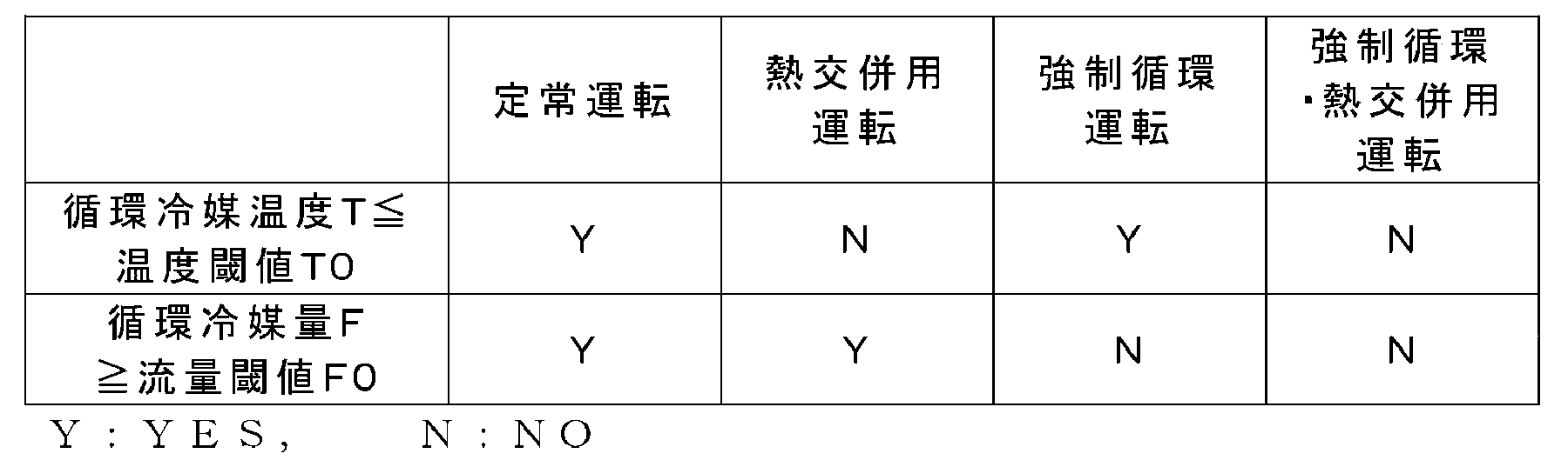
表1に示すように、循環冷媒温度Tが所定の温度閾値T0以下であり、且つ、循環冷媒量Fが所定の流量閾値F0以上である場合には、制御装置7は冷却システム2の定常運転を行う。循環冷媒温度Tが温度閾値T0を上回り、且つ、循環冷媒量Fが流量閾値F0以上である場合には、制御装置7は冷却システム2の「熱交併用運転」を行う。循環冷媒温度Tが温度閾値T0以下であり、且つ、循環冷媒量Fが流量閾値F0未満である場合には、制御装置7は冷却システム2の「強制循環運転」を行う。循環冷媒温度Tが温度閾値T0を上回り、且つ、循環冷媒量Fが流量閾値F0未満である場合には、制御装置7は冷却システム2の「強制循環・熱交併用運転」を行う。
〔熱交併用運転〕
熱交併用運転の冷却システム2では、第1開閉弁43及び第2開閉弁44は開放されて、冷媒22は外部熱交換器31を流れる。槽内流路切替弁23は第1状態にあり、上部出口24が槽出口21aを介して往路管41と接続されている。流量調整弁51は開放されており、冷媒22は内部熱交換路5を流れる。流量調整弁51によって、内部熱交換路5を流れる冷媒22の流量が調整されてもよい。流路切替弁46は第1状態にあり、冷媒22は強制循環経路48を流れない。
熱交併用運転の冷却システム2では、第1開閉弁43及び第2開閉弁44は開放されて、冷媒22は外部熱交換器31を流れる。槽内流路切替弁23は第1状態にあり、上部出口24が槽出口21aを介して往路管41と接続されている。流量調整弁51は開放されており、冷媒22は内部熱交換路5を流れる。流量調整弁51によって、内部熱交換路5を流れる冷媒22の流量が調整されてもよい。流路切替弁46は第1状態にあり、冷媒22は強制循環経路48を流れない。
熱交併用運転の冷却システム2では、液浸槽21において発熱体20によって温められた液相の冷媒22は蒸発して気液二相(又は気相)となり、上部出口24を通じて液浸槽21から往路管41へ流出する。往路管41へ流れ出た冷媒22の一部は、外部熱交換器31で海水により冷却されて、凝縮して液相となって復路管42へ流入する。往路管41へ流れ出た冷媒22の残部は、内部熱交換路5を通って内部熱交換器6で冷水により冷却されて、凝縮して液相となって復路管42へ流入する。復路管42へ流入した冷媒22は、槽入口21bから液浸槽21へ戻る。このように、熱交併用運転の冷却システム2では、冷媒22の相変化によって、冷媒22が内部熱交換路5を含む冷媒循環路4を自然循環する。
熱交併用運転では、原則として外部熱交換器31と内部熱交換器6とが併用されるが、内部熱交換器6のみが使用されてもよい。この場合、上記の熱交併用運転の冷却システム2において、第1開閉弁43及び第2開閉弁44が閉止される。
〔強制循環運転〕
強制循環運転の冷却システム2では、第1開閉弁43及び第2開閉弁44は開放されて、冷媒22は外部熱交換器31を流れる。槽内流路切替弁23は第1状態にあり、上部出口24が槽出口21aを介して往路管41とが接続されている。流量調整弁51は閉止されており、冷媒22は内部熱交換路5を流れない。流路切替弁46は第2状態にあり、冷媒ポンプ47が稼働されて、冷媒22は強制循環経路48を流れる。
強制循環運転の冷却システム2では、第1開閉弁43及び第2開閉弁44は開放されて、冷媒22は外部熱交換器31を流れる。槽内流路切替弁23は第1状態にあり、上部出口24が槽出口21aを介して往路管41とが接続されている。流量調整弁51は閉止されており、冷媒22は内部熱交換路5を流れない。流路切替弁46は第2状態にあり、冷媒ポンプ47が稼働されて、冷媒22は強制循環経路48を流れる。
強制循環運転の冷却システム2では、液浸槽21において発熱体20によって温められた液相の冷媒22は蒸発して気相となり、気液二相(又は気相)の冷媒22は上部出口24を通じて液浸槽21から往路管41へ流出する。往路管41へ流れ出た冷媒22は、外部熱交換器31で海水により冷却されて、凝縮して液相となって復路管42へ流入する。復路管42へ流入した冷媒22は、強制循環経路48を経由して、槽入口21bから液浸槽21へ戻る。このように、熱交併用運転の冷却システム2では、冷媒ポンプ47の稼働により、冷媒22が強制的に循環させられる。
強制循環運転の冷却システム2において、液相(又は、気液二相)の冷媒22を循環させてもよい。この場合、上記強制循環運転の冷却システム2において、槽内流路切替弁23は第2状態にあり、下部出口25が槽出口21aを介して往路管41と接続され、揚液ポンプ27が稼働される。
このような強制循環運転の冷却システム2では、液浸槽21において発熱体20によって温められた液相の冷媒22は、下部出口25を通じて液浸槽21から往路管41へ圧送される。往路管41へ流れ出た冷媒22は、外部熱交換器31で海水により冷却されて、復路管42へ流入する。復路管42へ流入した冷媒22は、強制循環経路48を経由して、槽入口21bから液浸槽21へ戻る。このように、熱交併用運転の冷却システム2では、揚液ポンプ27及び冷媒ポンプ47の稼働により、液相(又は、気液二相)の冷媒22が強制的に循環させられる。
〔強制循環・熱交併用運転〕
強制循環・熱交併用運転の冷却システム2では、第1開閉弁43及び第2開閉弁44は開放されて、冷媒22は外部熱交換器31を流れる。槽内流路切替弁23は第2状態にあり、下部出口25が槽出口21aを介して往路管41と接続されて、揚液ポンプ27が稼働される。流量調整弁51は開放されており、冷媒22は内部熱交換路5及び内部熱交換器6を流れる。流量調整弁51によって、内部熱交換路5を流れる冷媒22の流量が調整されてもよい。流路切替弁46は第2状態にあり、冷媒ポンプ47が稼働され、冷媒22が強制循環経路48を流れる。
強制循環・熱交併用運転の冷却システム2では、第1開閉弁43及び第2開閉弁44は開放されて、冷媒22は外部熱交換器31を流れる。槽内流路切替弁23は第2状態にあり、下部出口25が槽出口21aを介して往路管41と接続されて、揚液ポンプ27が稼働される。流量調整弁51は開放されており、冷媒22は内部熱交換路5及び内部熱交換器6を流れる。流量調整弁51によって、内部熱交換路5を流れる冷媒22の流量が調整されてもよい。流路切替弁46は第2状態にあり、冷媒ポンプ47が稼働され、冷媒22が強制循環経路48を流れる。
強制循環・熱交併用運転の冷却システム2では、液浸槽21において発熱体20によって温められた液相(又は、気液二相)の冷媒22は、下部出口25を通じて液浸槽21から往路管41へ圧送される。往路管41へ流れ出た冷媒22の一部は、外部熱交換器31で海水により冷却されて、復路管42へ流入する。往路管41へ流れ出た冷媒22の残部は、内部熱交換路5を通って内部熱交換器6で冷水により冷却されて、復路管42へ流入する。復路管42へ流入した冷媒22は、強制循環経路48を経由して、槽入口21bから液浸槽21へ戻る。このように、強制循環・熱交併用運転の冷却システム2では、揚液ポンプ27及び冷媒ポンプ47の稼働により、液相(又は、気液二相)の冷媒22が強制的に循環させられる。そのうえ、強制循環・熱交併用運転の冷却システム2では、冷媒22の冷却に外部熱交換器31と内部熱交換器6とが併用される。これにより、強制循環・熱交併用運転の冷却システム2では、冷却システム2の冷却能力が定常運転時と比較して大幅に増幅される。
以上に説明したように、本実施形態に係る水中ビークル用冷却システム2は、水中ビークル1の耐圧殻10の内部に配置された液浸槽21、耐圧殻10の外部に配置された外部熱交換器31、液浸槽21の槽出口21aと外部熱交換器31の入口を接続する往路管41、及び、外部熱交換器31の出口と液浸槽21の槽入口21bとを接続する復路管42を有する密閉された冷媒循環路4を備える。そして、液浸槽21内において発熱体20を冷媒22に浸し、外部熱交換器31で冷媒22と耐圧殻10の周囲の水との熱交換が行われることにより、発熱体20が冷却される。
上記構成の水中ビークル用冷却システム2によれば、発熱体20を冷媒22に浸漬する液浸透(液浸漬)液冷方式により発熱体20が冷却されるうえ、冷媒22が耐圧殻10の周囲の水と直接的に熱交換される。液相の冷媒22が発熱体に直接的に接触して熱を除去するため、従来の空冷方式と比較して、冷却能力が格段に向上する。また、冷却能力の向上により、発熱体20の設置密度を高めることができ、システムの大型化を抑制することができる。また、冷却システム2は、空冷式と比較して静音であり、閉じられた空間であるビークル内11での発熱体20の冷却に好適である。
また、本実施形態に係る水中ビークル1は、耐圧殻10の内部に配置された内部熱交換器6を含み、上流端及び下流端が冷媒循環路4に接続され、内部熱交換器6を通って冷媒を流す内部熱交換路5と、冷媒循環路4と内部熱交換路5との接続部に設けられた流量調整弁51とを、更に備える。
これにより、外部熱交換器31の熱交換能力が低下したときには、外部熱交換器31と内部熱交換路5とを併用する、又は、熱交換器を外部熱交換器31から内部熱交換路5へ切り替えることにより、冷却システム2の冷却性能を維持することができる。
上記において、内部熱交換路5は、外部熱交換器31をバイパスして、往路管41から内部熱交換器6を通って復路管42へ冷媒22を流すものであってよい。
これにより、外部熱交換器31の熱交換能力が低下したときには、冷媒22を冷却するための熱交換器を外部熱交換器31から内部熱交換路5へ切り替えて、冷却システム2の冷却性能を維持することができる。
上記冷却システム2が、冷媒循環路4の循環冷媒温度Tを検出する第1検出器(例えば、温度計75)と、循環冷媒温度Tに基づいて外部熱交換器31の熱交換能力の不足を検知し、内部熱交換路5へ冷媒が流れるように流量調整弁51を制御する第1弁制御部71とを、更に備えてもよい。
これにより、外部熱交換器31の熱交換能力が低下したときに、自動的に冷媒22が内部熱交換路5を流れるように切り替わり、熱交換能力が低下を補うことができる。
また、本実施形態に係る冷却システム2は、冷媒22を圧送する冷媒ポンプ47を含み、上流端及び下流端が冷媒循環路4に接続された強制循環経路48と、強制循環経路48の上流端と冷媒循環路4との接続部に設けられた流路切替弁46とを、更に備える。
これにより、冷却システム2の冷却能力が不足する際には、冷媒22を強制的に循環させて、冷却能力を増幅させることができる。
上記冷却システム2が、冷媒循環路4の循環冷媒量Fを検出する第2検出器(例えば、流量計76)と、循環冷媒量Fに基づいて発熱体20の熱負荷に対する冷却能力の不足を検知し、強制循環経路48へ冷媒が流れるように流路切替弁46を制御する第2弁制御部72とを、更に備えてよい。
これにより、冷却システム2の冷却能力が不足する際には、自動的に冷媒22を強制的に循環させて、冷却能力を増幅させることができる。
また、本実施形態に係る冷却システム2において、液浸槽21が、槽内上部に設けられた上部出口24と、槽内下部に設けられた下部出口25と、上部出口24及び下部出口25を液浸槽21の槽出口21aと選択的に接続する槽内流路切替弁23とを、更に有する。
これにより、冷媒循環路4から往路管41へ気相の冷媒22が流出する状態(第1状態)と、液相(又は、気液二相)の冷媒22が流出する状態(第2状態)とを切り替えることができる。第1状態では、冷媒22の相変化を利用して冷媒22が冷媒循環路4を自然循環するので、冷媒22を強制的に循環させるためのエネルギーが不要となる。また、第2状態では、冷媒循環路4に液相(又は、気液二相)の冷媒22を循環させることができるので、冷却システム2の冷却能力をより高めることができる。
以上に本発明の好適な実施の形態を説明したが、本発明の要旨を逸脱しない範囲で、上記実施形態の具体的な構造及び/又は機能の詳細を変更したものも本発明に含まれ得る。
1 :水中ビークル
2 :冷却システム
4 :循環路
5 :内部熱交換路
6 :内部熱交換器
7 :制御装置
10 :耐圧殻
11 :ビークル内
12 :ビークル外
20,20A:発熱体
21 :液浸槽
21a :槽出口
21b :槽入口
22 :冷媒
23 :槽内流路切替弁
24 :上部出口
25 :下部出口
26 :揚液管
27 :揚液ポンプ
31 :外部熱交換器
41 :往路管
42 :復路管
43 :第1開閉弁
44 :第2開閉弁
46 :流路切替弁
47 :冷媒ポンプ
48 :強制循環経路
51 :流量調整弁
55 :消火流路
56 :消火用開閉弁
71 :演算処理装置
72 :記憶装置
75 :温度計
76 :流量計
81 :冷凍機
82 :海水流路
83 :冷凍回路
84 :冷水回路
85 :FCU
86 :海水ポンプ
87 :冷水ポンプ
F :循環冷媒量
F0 :流量閾値
T :循環冷媒温度
T0 :温度閾値
Claims (7)
- 水中ビークルの耐圧殻の内部に配置された液浸槽、前記耐圧殻の外部に配置された外部熱交換器、前記液浸槽の槽出口と前記外部熱交換器の入口とを接続する往路管、及び、前記外部熱交換器の出口と前記液浸槽の槽入口とを接続する復路管を有する密閉された冷媒循環路を備え、
前記液浸槽内において発熱体を冷媒に浸し、前記外部熱交換器で前記冷媒と前記耐圧殻の周囲の水との熱交換が行われることにより、前記発熱体が冷却される、
水中ビークル用冷却システム。 - 前記耐圧殻の内部に配置された内部熱交換器を含み、上流端及び下流端が前記冷媒循環路に接続され、前記内部熱交換器を通って前記冷媒を流す内部熱交換路と、
前記冷媒循環路と前記内部熱交換路との接続部に設けられた流量調整弁とを、更に備える、
請求項1に記載の水中ビークル用冷却システム。 - 前記内部熱交換路は、前記外部熱交換器をバイパスして、前記往路管から前記内部熱交換器を通って前記復路管へ前記冷媒を流すことを特徴とする、
請求項2に記載の水中ビークル用冷却システム。 - 前記冷媒循環路の循環冷媒温度を検出する第1検出器と、
前記循環冷媒温度に基づいて前記外部熱交換器の熱交換能力の不足を検知し、前記内部熱交換路へ前記冷媒が流れるように前記流量調整弁を制御する第1弁制御部とを、更に備える、
請求項2~3のいずれか一項に記載の水中ビークル用冷却システム。 - 前記冷媒を圧送する冷媒ポンプを含み、上流端及び下流端が前記冷媒循環路に接続された強制循環経路と、
前記強制循環経路の前記上流端と前記冷媒循環路との接続部に設けられた流路切替弁とを、更に備える、
請求項1~4のいずれか一項に記載の水中ビークル用冷却システム。 - 前記冷媒循環路の循環冷媒量を検出する第2検出器と、
前記循環冷媒量に基づいて前記発熱体の熱負荷に対する冷却能力の不足を検知し、前記強制循環経路へ前記冷媒が流れるように前記流路切替弁を制御する第2弁制御部とを、更に備える、
請求項5に記載の水中ビークル用冷却システム。 - 前記液浸槽が、槽内上部に設けられた上部出口と、槽内下部に設けられた下部出口と、前記上部出口及び前記下部出口を前記液浸槽の前記槽出口と選択的に接続する槽内流路切替弁とを、更に有する、
請求項1~6のいずれか一項に記載の水中ビークル用冷却システム。
Applications Claiming Priority (2)
| Application Number | Priority Date | Filing Date | Title |
|---|---|---|---|
| JP2019067108A JP7189065B2 (ja) | 2019-03-29 | 2019-03-29 | 水中ビークル用冷却システム |
| JP2019-067108 | 2019-03-29 |
Publications (1)
| Publication Number | Publication Date |
|---|---|
| WO2020203565A1 true WO2020203565A1 (ja) | 2020-10-08 |
Family
ID=72668985
Family Applications (1)
| Application Number | Title | Priority Date | Filing Date |
|---|---|---|---|
| PCT/JP2020/013377 Ceased WO2020203565A1 (ja) | 2019-03-29 | 2020-03-25 | 水中ビークル用冷却システム |
Country Status (2)
| Country | Link |
|---|---|
| JP (1) | JP7189065B2 (ja) |
| WO (1) | WO2020203565A1 (ja) |
Cited By (3)
| Publication number | Priority date | Publication date | Assignee | Title |
|---|---|---|---|---|
| CN114162301A (zh) * | 2021-12-17 | 2022-03-11 | 深圳市酷凌时代科技有限公司 | 水上散热系统 |
| CN116331465A (zh) * | 2023-03-15 | 2023-06-27 | 深海技术科学太湖实验室 | 一种原位载人平台温湿度控制系统 |
| WO2024107143A1 (en) * | 2022-11-14 | 2024-05-23 | Akkoc Teknoloji Limited Sirketi | An underwater vehicle with a cooling installation |
Families Citing this family (3)
| Publication number | Priority date | Publication date | Assignee | Title |
|---|---|---|---|---|
| CN112810747B (zh) | 2021-02-19 | 2024-12-03 | 中船(上海)节能技术有限公司 | 一种适用于气层减阻船舶的供气系统及船舶 |
| JP2023159767A (ja) * | 2022-04-20 | 2023-11-01 | 川崎重工業株式会社 | 冷却システム及び水中ビークル |
| JP2025124335A (ja) * | 2024-02-14 | 2025-08-26 | 三菱重工業株式会社 | 冷却システム |
Citations (4)
| Publication number | Priority date | Publication date | Assignee | Title |
|---|---|---|---|---|
| US4224804A (en) * | 1978-01-14 | 1980-09-30 | Bruker-Physik Ag | Hot-water supply for submarines and the like |
| US4474228A (en) * | 1982-08-24 | 1984-10-02 | The United States Of America As Represented By The Secretary Of The Navy | Closed cycle vaporization cooling system for underwater vehicle inner-to-outer hull heat transfer |
| US5979354A (en) * | 1996-12-30 | 1999-11-09 | Arzola; Javier Silvano | Submarine |
| WO2003022675A1 (en) * | 2001-09-10 | 2003-03-20 | Strachan & Henshaw Limited | Torpedo launch system |
-
2019
- 2019-03-29 JP JP2019067108A patent/JP7189065B2/ja active Active
-
2020
- 2020-03-25 WO PCT/JP2020/013377 patent/WO2020203565A1/ja not_active Ceased
Patent Citations (4)
| Publication number | Priority date | Publication date | Assignee | Title |
|---|---|---|---|---|
| US4224804A (en) * | 1978-01-14 | 1980-09-30 | Bruker-Physik Ag | Hot-water supply for submarines and the like |
| US4474228A (en) * | 1982-08-24 | 1984-10-02 | The United States Of America As Represented By The Secretary Of The Navy | Closed cycle vaporization cooling system for underwater vehicle inner-to-outer hull heat transfer |
| US5979354A (en) * | 1996-12-30 | 1999-11-09 | Arzola; Javier Silvano | Submarine |
| WO2003022675A1 (en) * | 2001-09-10 | 2003-03-20 | Strachan & Henshaw Limited | Torpedo launch system |
Cited By (4)
| Publication number | Priority date | Publication date | Assignee | Title |
|---|---|---|---|---|
| CN114162301A (zh) * | 2021-12-17 | 2022-03-11 | 深圳市酷凌时代科技有限公司 | 水上散热系统 |
| WO2024107143A1 (en) * | 2022-11-14 | 2024-05-23 | Akkoc Teknoloji Limited Sirketi | An underwater vehicle with a cooling installation |
| CN116331465A (zh) * | 2023-03-15 | 2023-06-27 | 深海技术科学太湖实验室 | 一种原位载人平台温湿度控制系统 |
| CN116331465B (zh) * | 2023-03-15 | 2024-01-26 | 深海技术科学太湖实验室 | 一种原位载人平台温湿度控制系统 |
Also Published As
| Publication number | Publication date |
|---|---|
| JP7189065B2 (ja) | 2022-12-13 |
| JP2020164054A (ja) | 2020-10-08 |
Similar Documents
| Publication | Publication Date | Title |
|---|---|---|
| JP7189065B2 (ja) | 水中ビークル用冷却システム | |
| JP6828821B2 (ja) | 相変化冷却装置および相変化冷却方法 | |
| JP5268317B2 (ja) | 油冷式空気圧縮機 | |
| JP6992411B2 (ja) | 機器冷却装置 | |
| KR100955036B1 (ko) | 선박의 냉각 시스템 | |
| JP2007071505A (ja) | 冷凍装置 | |
| CN110118493A (zh) | 用于具有冷却塔的冷却系统的热虹吸冷却器 | |
| JP6870621B2 (ja) | 燃料電池システム | |
| JP6335859B2 (ja) | 熱エネルギー回収システム | |
| JP5967315B2 (ja) | 蒸気生成装置及び蒸気生成ヒートポンプ | |
| JP2020092263A (ja) | 電子部品冷却装置 | |
| US20150330262A1 (en) | Thermal energy recovery device | |
| EP2762802B1 (en) | Chilled water system and method of operating chilled water system | |
| JP2010002090A (ja) | 冷凍サイクル装置 | |
| JPWO2014155993A1 (ja) | 給湯装置 | |
| JP5881379B2 (ja) | 漁船用冷凍装置 | |
| KR101323822B1 (ko) | 선박용 공조 장치 | |
| CN117940655A (zh) | 动力回收系统 | |
| JP5034367B2 (ja) | ヒートポンプ式給湯機 | |
| US20220140363A1 (en) | Fuel cell system | |
| TW202005706A (zh) | 逆滲透處理方法及系統 | |
| JP4929692B2 (ja) | 燃料電池冷却システム | |
| WO2019054076A1 (ja) | 機器温調装置 | |
| JP6170110B2 (ja) | 冷却装置および冷媒中継装置 | |
| JP6295121B2 (ja) | ターボ冷凍機 |
Legal Events
| Date | Code | Title | Description |
|---|---|---|---|
| 121 | Ep: the epo has been informed by wipo that ep was designated in this application |
Ref document number: 20785098 Country of ref document: EP Kind code of ref document: A1 |
|
| NENP | Non-entry into the national phase |
Ref country code: DE |
|
| 122 | Ep: pct application non-entry in european phase |
Ref document number: 20785098 Country of ref document: EP Kind code of ref document: A1 |