WO2020203553A1 - ダイヤフラムおよびダイヤフラム弁 - Google Patents
ダイヤフラムおよびダイヤフラム弁 Download PDFInfo
- Publication number
- WO2020203553A1 WO2020203553A1 PCT/JP2020/013342 JP2020013342W WO2020203553A1 WO 2020203553 A1 WO2020203553 A1 WO 2020203553A1 JP 2020013342 W JP2020013342 W JP 2020013342W WO 2020203553 A1 WO2020203553 A1 WO 2020203553A1
- Authority
- WO
- WIPO (PCT)
- Prior art keywords
- diaphragm
- bolt insertion
- bolt
- hole
- insertion tube
- Prior art date
- Legal status (The legal status is an assumption and is not a legal conclusion. Google has not performed a legal analysis and makes no representation as to the accuracy of the status listed.)
- Ceased
Links
Images




Classifications
-
- F—MECHANICAL ENGINEERING; LIGHTING; HEATING; WEAPONS; BLASTING
- F16—ENGINEERING ELEMENTS AND UNITS; GENERAL MEASURES FOR PRODUCING AND MAINTAINING EFFECTIVE FUNCTIONING OF MACHINES OR INSTALLATIONS; THERMAL INSULATION IN GENERAL
- F16J—PISTONS; CYLINDERS; SEALINGS
- F16J3/00—Diaphragms; Bellows; Bellows pistons
- F16J3/02—Diaphragms
-
- F—MECHANICAL ENGINEERING; LIGHTING; HEATING; WEAPONS; BLASTING
- F16—ENGINEERING ELEMENTS AND UNITS; GENERAL MEASURES FOR PRODUCING AND MAINTAINING EFFECTIVE FUNCTIONING OF MACHINES OR INSTALLATIONS; THERMAL INSULATION IN GENERAL
- F16K—VALVES; TAPS; COCKS; ACTUATING-FLOATS; DEVICES FOR VENTING OR AERATING
- F16K7/00—Diaphragm valves or cut-off apparatus, e.g. with a member deformed, but not moved bodily, to close the passage ; Pinch valves
- F16K7/12—Diaphragm valves or cut-off apparatus, e.g. with a member deformed, but not moved bodily, to close the passage ; Pinch valves with flat, dished, or bowl-shaped diaphragm
- F16K7/126—Diaphragm valves or cut-off apparatus, e.g. with a member deformed, but not moved bodily, to close the passage ; Pinch valves with flat, dished, or bowl-shaped diaphragm the seat being formed on a rib perpendicular to the fluid line
-
- F—MECHANICAL ENGINEERING; LIGHTING; HEATING; WEAPONS; BLASTING
- F16—ENGINEERING ELEMENTS AND UNITS; GENERAL MEASURES FOR PRODUCING AND MAINTAINING EFFECTIVE FUNCTIONING OF MACHINES OR INSTALLATIONS; THERMAL INSULATION IN GENERAL
- F16K—VALVES; TAPS; COCKS; ACTUATING-FLOATS; DEVICES FOR VENTING OR AERATING
- F16K1/00—Lift valves or globe valves, i.e. cut-off apparatus with closure members having at least a component of their opening and closing motion perpendicular to the closing faces
- F16K1/32—Details
- F16K1/48—Attaching valve members to screw-spindles
-
- F—MECHANICAL ENGINEERING; LIGHTING; HEATING; WEAPONS; BLASTING
- F16—ENGINEERING ELEMENTS AND UNITS; GENERAL MEASURES FOR PRODUCING AND MAINTAINING EFFECTIVE FUNCTIONING OF MACHINES OR INSTALLATIONS; THERMAL INSULATION IN GENERAL
- F16K—VALVES; TAPS; COCKS; ACTUATING-FLOATS; DEVICES FOR VENTING OR AERATING
- F16K1/00—Lift valves or globe valves, i.e. cut-off apparatus with closure members having at least a component of their opening and closing motion perpendicular to the closing faces
- F16K1/32—Details
- F16K1/48—Attaching valve members to screw-spindles
- F16K1/487—Attaching valve members to screw-spindles by a fixing element extending in the axial direction of the spindle, e.g. a screw
-
- F—MECHANICAL ENGINEERING; LIGHTING; HEATING; WEAPONS; BLASTING
- F16—ENGINEERING ELEMENTS AND UNITS; GENERAL MEASURES FOR PRODUCING AND MAINTAINING EFFECTIVE FUNCTIONING OF MACHINES OR INSTALLATIONS; THERMAL INSULATION IN GENERAL
- F16K—VALVES; TAPS; COCKS; ACTUATING-FLOATS; DEVICES FOR VENTING OR AERATING
- F16K27/00—Construction of housing; Use of materials therefor
- F16K27/02—Construction of housing; Use of materials therefor of lift valves
- F16K27/0236—Diaphragm cut-off apparatus
Definitions
- the present invention relates to a diaphragm and a diaphragm valve used for a diaphragm valve.
- a valve seat is provided in the fluid passage, and the diaphragm is deformed to abut and separate the valve seat and the diaphragm to open and close the fluid passage.
- a diaphragm valve is known (Patent Document 1).
- the diaphragm used for such a valve is usually made of resin or rubber, is inserted between the body and the bonnet, and is fixed to the body and the bonnet with bolts.
- the regulation for fixing the diaphragm with a bolt (for example, tightening with a predetermined torque value) is set, but the regulation may not be observed. Therefore, the diaphragm is overtightened due to the bolt. There is a problem that it may be damaged.
- An object of the present invention is to solve problems such as deterioration of airtightness due to insufficient tightening of bolts and damage to the diaphragm due to overtightening of bolts, reduction of variations in performance such as durability of the diaphragm, and simplification of tightening work.
- the purpose of the present invention is to provide a diaphragm and a diaphragm valve that can be changed.
- the diaphragm according to the present invention is a diaphragm for a diaphragm valve that is sandwiched between a body and a bonnet and fixed to the body and the bonnet with bolts, and is provided with a through hole through which the bolt is inserted.
- a metal bolt insertion tube through which the bolt can be inserted is fitted therein, and the height of the bolt insertion tube is made smaller than the height of the through hole.
- the diaphragm valve according to the present invention is said to be between a body provided with a fluid passage, a diaphragm that opens and closes the fluid passage by contacting and separating from a valve seat formed in the fluid passage, and the body.
- a bonnet that holds the peripheral edge of the diaphragm, a stem that is connected to the diaphragm via a hanging bracket, and an operating mechanism for raising and lowering the stem are provided, and the diaphragm is attached to the body and the bonnet by bolts.
- the diaphragm is provided with a through hole through which the bolt is inserted, and a metal bolt insertion tube through which the bolt can be inserted is fitted in the through hole.
- the height of the bolt insertion tube is characterized in that it is made smaller than the height of the through hole.
- the material of the diaphragm is not particularly limited, but rubber materials such as natural rubber, nitrile rubber, styrene rubber, fluororubber (FPM), ethylene propylene rubber (EPDM), and silicone rubber are preferably used.
- the diaphragm may have a single-layer structure made of the above rubber material, or may have a two-layer structure in which a rubber layer made of the above rubber material and a synthetic resin layer such as polytetrafluoroethylene resin (PTFE) are laminated. It may be a thing.
- the bolt insertion tube is made of metal and may be integrated with the diaphragm by molding.
- the bolt insertion tube may be fitted into the through hole after the diaphragm is molded (vulcanized) by the same method as before, and the bolt insertion tube is first fitted into the diaphragm before vulcanization.
- Vulcanization molding may be performed, and the latter is more preferable.
- the diaphragm valve may be a wear type in which a diaphragm is provided in the fluid passage, or may be called a wearless type in which the fluid passage is not provided with a diaphragm for receiving a diaphragm.
- At least one concave portion or convex portion is provided on the outer circumference of the diaphragm bolt insertion tube.
- the fit between the through hole and the bolt insertion tube may be a gap in terms of preventing damage to the diaphragm, but from the point of view of ease of handling, it is a fitting that can prevent the bolt insertion tube from falling off. It is preferable to have.
- the diaphragm and the diaphragm valve for the diaphragm valve of the present invention proper tightening is possible without using a torque wrench, and the tightening work is simplified. Further, by eliminating the overtightening, the diaphragm is prevented from being damaged, and by performing the tightening uniformly, it is also possible to prevent the performance of the diaphragm from being deteriorated due to insufficient tightening.
- FIG. 1 is a vertical sectional view showing an overall configuration of a diaphragm for a diaphragm valve according to the present invention and a first embodiment of the diaphragm valve.
- FIG. 2 is a side view of the same.
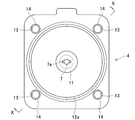
- FIG. 3 is a plan view of the diaphragm.
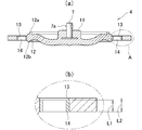
- FIG. 4A is a partial cross-sectional view taken along the line XX of FIG. 3, and
- FIG. 4B is an enlarged cross-sectional view showing the height relationship between the through hole and the bolt insertion tube.
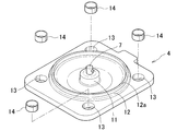
- FIG. 5 is an exploded perspective view of the diaphragm. 6A and 6B are views showing one embodiment of a bolt insertion tube, where FIG. 6A is a perspective view and FIG. 6B is a front view.
- FIG. 7A and 7B are views showing another embodiment of the bolt insertion tube, where FIG. 7A is a perspective view and FIG. 7B is a front view.
- 8A and 8B are views showing still another embodiment of the bolt insertion tube required to be realized by molding processing such as vulcanization molding, where FIG. 8A is a perspective view and FIG. 8B is a front view.
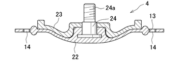
- FIG. 9 is a vertical sectional view showing an overall configuration of a diaphragm for a diaphragm valve according to the present invention and a second embodiment of the diaphragm valve.
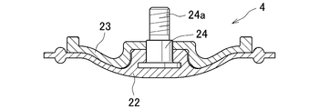
- FIG. 10 is a front sectional view showing another embodiment of the diaphragm. It is a cross-sectional view along the diagonal line of the diaphragm shown in FIG. 10, and is a diagram corresponding to FIG. 4 (a).
- FIGS. 1 to 5 The diaphragm for the diaphragm valve of the present invention and the first embodiment of the diaphragm valve are shown in FIGS. 1 to 5.
- up / down / left / right means up / down / left / right in FIG.
- the top, bottom, left and right are for convenience, and when installed, the top and bottom may be upside down or horizontal.
- the diaphragm valve 1 is wear-type and automatic, and as shown in FIG. 1, the body 2 has a fluid inflow passage 2a and a fluid outflow passage 2b extending to the left and right, and the fluid inflow passage 2a and the fluid outflow of the body 2.
- a weir 3 as a valve seat provided between the passage 2b, a diaphragm 4 that opens and closes between the fluid inflow passage 2a and the fluid outflow passage 2b by contacting and separating from the upper surface of the weir 3.
- a bonnet 5 that holds the peripheral edge of the diaphragm 4 between the body 2 and the stem 6, a stem 6 that is connected to the diaphragm 4 via a hanging metal fitting 7, a diaphragm retainer 8 that is fixed to the lower end of the stem 6, and a stem 6. It is provided with an operation mechanism 9 that moves the diaphragm 4 up and down to move the diaphragm 4 in the open or closed direction.
- the diaphragm 4 has a single-layer structure made of a rubber material, a resin, and an elastomer, has a rectangular shape when viewed from above, and is inserted between the body 2 and the bonnet 5 as shown in FIG. , Is fixed to the body 2 and the bonnet 5 with a bolt 10.
- the hanging metal fitting 7 is provided with a hook 7a that is inserted into the stem 6 to prevent it from coming off.
- the operating mechanism 9 moves the piston fixed to the stem 6 up and down by compressed air against the urging force of the compression coil spring, or simply moves up and down by compressed air. Or
- a columnar projecting portion 11 projecting upward is provided in the center of the diaphragm 4.
- the lower part of the hanging metal fitting 7 connected to the stem 6 is embedded in the protruding portion 11.
- a circular holding portion 12 is provided so as to be concentric with the protruding portion 11.
- the sandwiching portion 12 is a portion sandwiched between the body 2 and the bonnet 5, and the upper surface of the sandwiching portion 12 is provided with a protrusion 12a that fits into a recess provided on the lower surface of the bonnet 5.
- the lower surface of the body 12 is provided with a protrusion 12b that fits into a recess provided on the upper surface of the body 2.
- the diaphragm valve 1 of this embodiment is provided in the through holes 13 provided at the four corners of the square portion as shown in FIGS. 4 and 5. It differs from the conventional one in that it has a shape in which a metal bolt insertion tube 14 is fitted.
- the through hole 13 has a circular cross section and has a diameter larger than the diameter through which the bolt insertion cylinder can be inserted.
- the bolt insertion cylinder 14 is a short cylinder, and its inner diameter is set to a size that allows the bolt 10 to be inserted.
- the outer peripheral surface of the bolt insertion cylinder 14 has an appropriate shape suitable for fitting into the through hole 13. An example thereof is shown in FIGS. 6 to 8.
- the outer peripheral surface of the bolt insertion cylinder 14 is a cylindrical surface.
- the cylindrical surface may be a completely smooth cylindrical surface, but it is more preferable that the cylindrical surface is processed to increase the friction coefficient by knurling, satin finish, or the like.
- the bolt insertion cylinder 14 is assumed to be provided with an annular convex portion 16 on the outer peripheral surface of the central portion in the axial direction of the cylindrical body 15.
- the diaphragm 4 after molding is rearranged. It is a bolt insertion cylinder that is easy to insert when inserting from and is hard to fall off or come off.
- the bolt insertion cylinder 14 is provided with an annular concave portion 18 on the outer peripheral surface of the axially central portion of the cylindrical body 17, and an annular convex portion 19 is provided on the axially central portion of the concave portion 18. It is supposed to have been done. In this embodiment, by inserting the diaphragm into the diaphragm before vulcanization first, rubber flows into the recess 18 during vulcanization, and the bolt insertion tube 14 is less likely to fall off or come off.
- the tightening work is simplified. Moreover, by eliminating overtightening, damage to the diaphragm is prevented, and by tightening uniformly, variations are reduced, resulting in external leakage due to insufficient tightening and deterioration of the durability performance of the diaphragm. Is also prevented.
- FIGS. 1 and 2 show an automatic diaphragm valve 1 using compressed air
- the above-mentioned diaphragm 4 has a stem 6 by manually rotating the handle 21 as shown in FIG. It can also be applied to a manual diaphragm valve 20 that moves up and down.
- FIG. 9 the parts having the same functions as those in FIG. 1 are designated by the same reference numerals as those in FIG. 1, and the description thereof will be omitted.
- FIG. 3 shows a diaphragm 4 having a single-layer structure made of a rubber material, a resin, and an elastomer.
- a resin is attached to the side in contact with the weir 3. It may have a two-layer structure of a diaphragm.
- the diaphragm 4 may have a two-layer structure consisting of a resin layer (for example, made of PTFE) 22 on the side in contact with the weir 3 and a rubber layer 23 on the side in contact with the diaphragm retainer 8.
- a resin layer for example, made of PTFE
- FIG. 10 it becomes a part up to the laminate including the rubber material, the resin, and the elastomer part, and in the type shown in FIG. 10, the bolt insertion tube 14 is fitted as shown in FIG. A through hole 13 to be inserted is provided in the resin layer 22.
- a male screw portion 24a that can be screwed to the female screw portion provided on the sleeve 25 is provided on the upper portion of the hanging metal fitting 24 instead of the hook.
- the present invention it is possible to contribute to improving the performance of diaphragms and diaphragm valves for diaphragm valves widely used in production processes of semiconductors, biotechnology, pharmaceuticals and the like.
- Diaphragm valve 2 Body 2a: Fluid inflow passage (fluid passage) 2b: Fluid outflow passage (fluid passage) 4: Diaphragm 5: Bonnet 6: Stem 7: Hanging bracket 9: Operation mechanism 10: Bolt 13: Through hole 14: Bolt insertion cylinder 16: Convex 18: Concave 19: Convex 20: Diaphragm valve
Landscapes
- Engineering & Computer Science (AREA)
- General Engineering & Computer Science (AREA)
- Mechanical Engineering (AREA)
- Diaphragms And Bellows (AREA)
- Fluid-Driven Valves (AREA)
- Valve Housings (AREA)
Abstract
Description
2:ボディ
2a:流体流入通路(流体通路)
2b:流体流出通路(流体通路)
4:ダイヤフラム
5:ボンネット
6:ステム
7:吊り金具
9:操作機構
10:ボルト
13:貫通孔
14:ボルト挿通筒
16:凸部
18:凹部
19:凸部
20:ダイヤフラム弁
Claims (6)
- ボディ及びボンネットに挟持され、ボルトで前記ボディおよび前記ボンネットに固定されるダイヤフラム弁用のダイヤフラムであって、
前記ボルトが挿通される貫通孔が設けられており、前記貫通孔に、前記ボルトが挿通できる金属製のボルト挿通筒が嵌め入れられており、前記ボルト挿通筒の高さは、前記貫通孔の高さよりも小さくなされていることを特徴とするダイヤフラム。 - 前記ボルト挿通筒の外周に少なくとも1つの凹部または凸部が設けられていることを特徴とする請求項1のダイヤフラム。
- 前記ボルト挿通筒が金属製であり、成型によって前記ダイヤフラムと一体となっていることを特徴とする請求項1または2のダイヤフラム。
- 流体通路が設けられているボディと、前記流体通路に形成された弁座に当接・離隔することにより前記流体通路を開閉するダイヤフラムと、前記ボディとの間で前記ダイヤフラムの周縁部を保持するボンネットと、前記ダイヤフラムに対して吊り金具を介して接続されたステムと、前記ステムを昇降させるための操作機構とを備え、前記ダイヤフラムがボルトによって前記ボディおよび前記ボンネットに固定されているダイヤフラム弁において、
前記ダイヤフラムに、前記ボルトが挿通される貫通孔が設けられており、前記貫通孔に、前記ボルトが挿通できる金属製のボルト挿通筒が嵌め入れられており、前記ボルト挿通筒の高さは、前記貫通孔の高さよりも小さくなされていることを特徴とするダイヤフラム弁。 - 前記ボルト挿通筒の外周に少なくとも1つの凹部または凸部が設けられていることを特徴とする請求項4のダイヤフラム弁。
- 前記ボルト挿通筒が金属製であり、成型によって前記ダイヤフラムと一体となっていることを特徴とする請求項4または5のダイヤフラム弁。
Priority Applications (5)
| Application Number | Priority Date | Filing Date | Title |
|---|---|---|---|
| SG11202110097SA SG11202110097SA (en) | 2019-03-29 | 2020-03-25 | Diaphragm and diaphragm valve |
| KR1020217031507A KR20210134723A (ko) | 2019-03-29 | 2020-03-25 | 다이어프램 및 다이어프램 밸브 |
| CN202080024294.5A CN113646562A (zh) | 2019-03-29 | 2020-03-25 | 隔膜及隔膜阀 |
| US17/598,444 US20220186844A1 (en) | 2019-03-29 | 2020-03-25 | Diaphragm and diaphragm valve |
| JP2021511870A JPWO2020203553A1 (ja) | 2019-03-29 | 2020-03-25 |
Applications Claiming Priority (2)
| Application Number | Priority Date | Filing Date | Title |
|---|---|---|---|
| JP2019065462 | 2019-03-29 | ||
| JP2019-065462 | 2019-03-29 |
Publications (1)
| Publication Number | Publication Date |
|---|---|
| WO2020203553A1 true WO2020203553A1 (ja) | 2020-10-08 |
Family
ID=72667793
Family Applications (1)
| Application Number | Title | Priority Date | Filing Date |
|---|---|---|---|
| PCT/JP2020/013342 Ceased WO2020203553A1 (ja) | 2019-03-29 | 2020-03-25 | ダイヤフラムおよびダイヤフラム弁 |
Country Status (7)
| Country | Link |
|---|---|
| US (1) | US20220186844A1 (ja) |
| JP (1) | JPWO2020203553A1 (ja) |
| KR (1) | KR20210134723A (ja) |
| CN (1) | CN113646562A (ja) |
| SG (1) | SG11202110097SA (ja) |
| TW (1) | TW202104782A (ja) |
| WO (1) | WO2020203553A1 (ja) |
Cited By (5)
| Publication number | Priority date | Publication date | Assignee | Title |
|---|---|---|---|---|
| DE102020130652A1 (de) | 2020-11-19 | 2022-05-19 | Gemü Gebr. Müller Apparatebau Gmbh & Co. Kommanditgesellschaft | Membran für ein Membranventil, mehrteilige Membran, Membranventil, Verfahren zur Montage |
| EP4098913A1 (de) | 2021-06-01 | 2022-12-07 | Gregor Gaida | Membranventil tiefsitz |
| EP4180696A1 (de) * | 2021-11-11 | 2023-05-17 | SISTO Armaturen S.A. | Flexibles druckverteilungselement |
| GB2616460A (en) * | 2022-03-10 | 2023-09-13 | Heap And Partners Ltd | Diaphragm and diaphragm valve |
| JP2023169082A (ja) * | 2022-05-16 | 2023-11-29 | 日本ダイヤバルブ株式会社 | ダイヤフラム |
Families Citing this family (2)
| Publication number | Priority date | Publication date | Assignee | Title |
|---|---|---|---|---|
| DE102021130951A1 (de) * | 2021-11-25 | 2023-05-25 | Gemü Gebr. Müller Apparatebau Gmbh & Co. Kommanditgesellschaft | Verbindungsvorrichtung und Membranventil |
| CN121474372A (zh) * | 2026-01-08 | 2026-02-06 | 科讯工业制造(深圳)有限公司 | 一种用于半导体cmp设备的研磨液隔膜阀及其组装方法 |
Citations (3)
| Publication number | Priority date | Publication date | Assignee | Title |
|---|---|---|---|---|
| US6047953A (en) * | 1999-04-27 | 2000-04-11 | Jacob, Jr.; Eugene W. | Diaphragm compression restrainer |
| JP2000165125A (ja) * | 1998-11-27 | 2000-06-16 | Sansei Denki Kk | 携帯無線機用の複合アンテナユニット、および、その構成方法 |
| JP2000291658A (ja) * | 1999-04-05 | 2000-10-20 | Sunny Sangyo Kk | 構造部材の製造方法及び構造部材 |
Family Cites Families (7)
| Publication number | Priority date | Publication date | Assignee | Title |
|---|---|---|---|---|
| US6241213B1 (en) * | 2000-03-07 | 2001-06-05 | Itt Manufacturing Enterprises, Inc. | Diaphragm valve |
| JP5054904B2 (ja) * | 2005-08-30 | 2012-10-24 | 株式会社フジキン | ダイレクトタッチ型メタルダイヤフラム弁 |
| WO2011049705A1 (en) * | 2009-10-19 | 2011-04-28 | Parker-Hannifin Corporation | Seal assembly |
| JP5964139B2 (ja) * | 2012-05-30 | 2016-08-03 | 株式会社フジキン | ダイヤフラム及びダイヤフラム弁 |
| JP5964140B2 (ja) | 2012-05-30 | 2016-08-03 | 株式会社フジキン | ダイヤフラム及びダイヤフラム弁 |
| CN102691807A (zh) * | 2012-06-05 | 2012-09-26 | 昆山新莱洁净应用材料股份有限公司 | 可限位的隔膜阀 |
| JP6410479B2 (ja) * | 2014-05-29 | 2018-10-24 | 株式会社フジキン | ダイヤフラム弁およびその組立て方法 |
-
2020
- 2020-03-25 US US17/598,444 patent/US20220186844A1/en not_active Abandoned
- 2020-03-25 SG SG11202110097SA patent/SG11202110097SA/en unknown
- 2020-03-25 WO PCT/JP2020/013342 patent/WO2020203553A1/ja not_active Ceased
- 2020-03-25 JP JP2021511870A patent/JPWO2020203553A1/ja active Pending
- 2020-03-25 KR KR1020217031507A patent/KR20210134723A/ko not_active Ceased
- 2020-03-25 CN CN202080024294.5A patent/CN113646562A/zh active Pending
- 2020-03-27 TW TW109110440A patent/TW202104782A/zh unknown
Patent Citations (3)
| Publication number | Priority date | Publication date | Assignee | Title |
|---|---|---|---|---|
| JP2000165125A (ja) * | 1998-11-27 | 2000-06-16 | Sansei Denki Kk | 携帯無線機用の複合アンテナユニット、および、その構成方法 |
| JP2000291658A (ja) * | 1999-04-05 | 2000-10-20 | Sunny Sangyo Kk | 構造部材の製造方法及び構造部材 |
| US6047953A (en) * | 1999-04-27 | 2000-04-11 | Jacob, Jr.; Eugene W. | Diaphragm compression restrainer |
Cited By (10)
| Publication number | Priority date | Publication date | Assignee | Title |
|---|---|---|---|---|
| DE102020130652A1 (de) | 2020-11-19 | 2022-05-19 | Gemü Gebr. Müller Apparatebau Gmbh & Co. Kommanditgesellschaft | Membran für ein Membranventil, mehrteilige Membran, Membranventil, Verfahren zur Montage |
| WO2022106267A1 (de) * | 2020-11-19 | 2022-05-27 | Gemü Gebr. Müller Apparatebau Gmbh & Co. Kommanditgesellschaft | Membran für ein membranventil, mehrteilige membran, membranventil, verfahren zur montage |
| CN116601412A (zh) * | 2020-11-19 | 2023-08-15 | 盖米工业设备有限两合公司 | 用于隔膜阀的隔膜、多部件隔膜、隔膜阀、装配方法 |
| US12398813B2 (en) | 2020-11-19 | 2025-08-26 | Gemü Gebr. Müller Apparatebau Gmbh & Co. Kommanditgesellschaft | Diaphragm for a diaphragm valve, multi-part diaphragm, diaphragm valve, method for installation |
| EP4098913A1 (de) | 2021-06-01 | 2022-12-07 | Gregor Gaida | Membranventil tiefsitz |
| EP4180696A1 (de) * | 2021-11-11 | 2023-05-17 | SISTO Armaturen S.A. | Flexibles druckverteilungselement |
| GB2616460A (en) * | 2022-03-10 | 2023-09-13 | Heap And Partners Ltd | Diaphragm and diaphragm valve |
| JP2023169082A (ja) * | 2022-05-16 | 2023-11-29 | 日本ダイヤバルブ株式会社 | ダイヤフラム |
| JP7399232B2 (ja) | 2022-05-16 | 2023-12-15 | 日本ダイヤバルブ株式会社 | ダイヤフラム |
| US12055240B2 (en) | 2022-05-16 | 2024-08-06 | Nippon Daiya Valve Co., Ltd. | Diaphragm and diaphragm valve |
Also Published As
| Publication number | Publication date |
|---|---|
| CN113646562A (zh) | 2021-11-12 |
| TW202104782A (zh) | 2021-02-01 |
| SG11202110097SA (en) | 2021-10-28 |
| US20220186844A1 (en) | 2022-06-16 |
| JPWO2020203553A1 (ja) | 2020-10-08 |
| KR20210134723A (ko) | 2021-11-10 |
Similar Documents
| Publication | Publication Date | Title |
|---|---|---|
| WO2020203553A1 (ja) | ダイヤフラムおよびダイヤフラム弁 | |
| RU2461740C2 (ru) | Мембранный исполнительный механизм | |
| CN1107831C (zh) | 流量控制装置 | |
| US5261442A (en) | Diaphragm valve with leak detection | |
| CN102713380B (zh) | 隔膜和隔膜阀 | |
| US9851012B2 (en) | Vacuum valve seal | |
| CN101910697B (zh) | 控制阀内件和密封 | |
| US20070241301A1 (en) | Valve diaphragm with a fluoropolymer layer | |
| TWI485342B (zh) | 膜片閥 | |
| US7401760B2 (en) | Vacuum regulating valve | |
| JP2007534893A (ja) | 延伸ストロークバルブおよびダイアフラム | |
| JP3861206B2 (ja) | 流体制御器 | |
| US10359120B2 (en) | Fluid controller | |
| US3631882A (en) | Diaphragm valve | |
| CN1465000A (zh) | 恒压调节器 | |
| KR20210015764A (ko) | 핀치 밸브 | |
| US20060289824A1 (en) | Valve diaphragm with a compression restraining ring, and valve including same | |
| JP7377009B2 (ja) | ピンチバルブ | |
| US10247175B2 (en) | Wax-motor with high cycle life | |
| US3948480A (en) | Rotary ball valve | |
| CA2520964C (en) | O-ring forming sealing washer | |
| KR102357776B1 (ko) | 밸브 | |
| KR102928207B1 (ko) | 다이어프램 밸브와 이 밸브용 밸브시트의 교환 방법 | |
| US6155535A (en) | Diaphragm compression limit stops | |
| KR20200088806A (ko) | 다이어프램 밸브 |
Legal Events
| Date | Code | Title | Description |
|---|---|---|---|
| 121 | Ep: the epo has been informed by wipo that ep was designated in this application |
Ref document number: 20782920 Country of ref document: EP Kind code of ref document: A1 |
|
| ENP | Entry into the national phase |
Ref document number: 2021511870 Country of ref document: JP Kind code of ref document: A |
|
| ENP | Entry into the national phase |
Ref document number: 20217031507 Country of ref document: KR Kind code of ref document: A |
|
| NENP | Non-entry into the national phase |
Ref country code: DE |
|
| 122 | Ep: pct application non-entry in european phase |
Ref document number: 20782920 Country of ref document: EP Kind code of ref document: A1 |