WO2020203363A1 - サーバ、サーバ管理システム、サーバ管理方法及びサーバ管理プログラム - Google Patents
サーバ、サーバ管理システム、サーバ管理方法及びサーバ管理プログラム Download PDFInfo
- Publication number
- WO2020203363A1 WO2020203363A1 PCT/JP2020/012396 JP2020012396W WO2020203363A1 WO 2020203363 A1 WO2020203363 A1 WO 2020203363A1 JP 2020012396 W JP2020012396 W JP 2020012396W WO 2020203363 A1 WO2020203363 A1 WO 2020203363A1
- Authority
- WO
- WIPO (PCT)
- Prior art keywords
- unit
- light emitting
- server
- lamp
- identification information
- Prior art date
- Legal status (The legal status is an assumption and is not a legal conclusion. Google has not performed a legal analysis and makes no representation as to the accuracy of the status listed.)
- Ceased
Links
Images



Classifications
-
- H—ELECTRICITY
- H04—ELECTRIC COMMUNICATION TECHNIQUE
- H04L—TRANSMISSION OF DIGITAL INFORMATION, e.g. TELEGRAPHIC COMMUNICATION
- H04L43/00—Arrangements for monitoring or testing data switching networks
- H04L43/06—Generation of reports
- H04L43/065—Generation of reports related to network devices
-
- G—PHYSICS
- G06—COMPUTING OR CALCULATING; COUNTING
- G06F—ELECTRIC DIGITAL DATA PROCESSING
- G06F1/00—Details not covered by groups G06F3/00 - G06F13/00 and G06F21/00
- G06F1/26—Power supply means, e.g. regulation thereof
- G06F1/32—Means for saving power
- G06F1/3203—Power management, i.e. event-based initiation of a power-saving mode
- G06F1/3206—Monitoring of events, devices or parameters that trigger a change in power modality
- G06F1/3209—Monitoring remote activity, e.g. over telephone lines or network connections
-
- G—PHYSICS
- G06—COMPUTING OR CALCULATING; COUNTING
- G06F—ELECTRIC DIGITAL DATA PROCESSING
- G06F1/00—Details not covered by groups G06F3/00 - G06F13/00 and G06F21/00
- G06F1/26—Power supply means, e.g. regulation thereof
- G06F1/32—Means for saving power
- G06F1/3203—Power management, i.e. event-based initiation of a power-saving mode
- G06F1/3234—Power saving characterised by the action undertaken
- G06F1/3287—Power saving characterised by the action undertaken by switching off individual functional units in the computer system
-
- H—ELECTRICITY
- H04—ELECTRIC COMMUNICATION TECHNIQUE
- H04L—TRANSMISSION OF DIGITAL INFORMATION, e.g. TELEGRAPHIC COMMUNICATION
- H04L43/00—Arrangements for monitoring or testing data switching networks
- H04L43/04—Processing captured monitoring data, e.g. for logfile generation
-
- H—ELECTRICITY
- H04—ELECTRIC COMMUNICATION TECHNIQUE
- H04Q—SELECTING
- H04Q9/00—Arrangements in telecontrol or telemetry systems for selectively calling a substation from a main station, in which substation desired apparatus is selected for applying a control signal thereto or for obtaining measured values therefrom
-
- G—PHYSICS
- G08—SIGNALLING
- G08B—SIGNALLING SYSTEMS, e.g. PERSONAL CALLING SYSTEMS; ORDER TELEGRAPHS; ALARM SYSTEMS
- G08B5/00—Visible signalling systems, e.g. visible personal calling systems or remote indication of seats occupied
- G08B5/22—Visible signalling systems, e.g. visible personal calling systems or remote indication of seats occupied using electric transmission; using electromagnetic transmission
- G08B5/36—Visible signalling systems, e.g. visible personal calling systems or remote indication of seats occupied using electric transmission; using electromagnetic transmission using visible light sources
Definitions
- the present invention relates to a server, a server management system, a server management method, and a server management program.
- Patent Document 1 discloses a technique capable of turning off a lamp provided on a server by performing a predetermined operation on the server to suppress power consumption.
- the role of the lamp is to display the status of the server and individual identification. Therefore, it is difficult to operate the server by turning off the lamp.
- the server is monitored and controlled from a remote location. If the lamp is provided in such a server, the lamp can be turned off to operate the server.
- Patent Document 2 discloses a technique capable of controlling a server from a remote location.
- Patent Document 3 discloses a technique capable of confirming the display of the LED (Light Emitting Diode) of the server from a remote location.
- Patent Documents 4 and 5 disclose techniques capable of controlling the amount of light of an LED.
- the server has lamps that cannot be monitored and controlled from a remote location. For such a lamp, it was still necessary to keep the lamp lit.
- Patent Document 1 With the technique described in Patent Document 1, it is not possible to suppress the power consumption by turning off the lamp of the server from a remote location. Further, although the technique described in Patent Document 2 can control a server from a remote location, it does not control a lamp. Further, the technique described in Patent Document 3 is limited to confirming the display of the lamp, and does not control the lamp. Further, the techniques described in Patent Documents 4 and 5 are techniques for controlling the amount of light so as not to give stress to the user standing in front of the device, and do not perform power saving control of the server. .. As described above, there is no technology for controlling the light emitting state of the lamp provided in the server from a remote location.
- an object of the present invention is to provide a server, a server management system, a server management method, and a program that solve the above-mentioned problems.
- the server obtains via a communication means that communicates with another device via a network, identification information that identifies one or more functional units that perform a predetermined function, and the communication means.
- a light emitting control means for controlling the light emitting state of the light emitting member provided in the functional unit identified by the identification information based on the control information for controlling the light emitting state of the light emitting member provided in the functional unit. To be equipped.
- the server management system is one or more of a server management device connected to a network, a communication means for communicating with the server management device via the network, and a predetermined function.
- a server management device connected to a network
- a communication means for communicating with the server management device via the network
- a predetermined function Provided to the functional unit identified by the identification information based on the identification information for identifying the functional unit and the control information for controlling the light emitting state of the light emitting member provided in the functional unit acquired via the communication unit. It includes a server having a light emitting control means for controlling the light emitting state of the light emitting member.
- the server management method is acquired in the communication step with identification information that identifies one or more functional units that communicate with other devices via a network and perform a predetermined function.
- the light emitting state of the light emitting member provided in the functional unit identified by the identification information is controlled based on the control information for controlling the light emitting state of the light emitting member provided in the functional unit.
- the server management program causes a computer to communicate with another device via a network, and identifies one or more functional units that perform a predetermined function related to the server, and the above-mentioned identification information. Based on the control information for controlling the light emitting state of the light emitting member provided in the functional unit acquired in the communication step, the light emitting state of the light emitting member provided in the functional unit identified by the identification information is controlled. ..
- the effect that the power consumption of the server can be suppressed from a remote location can be obtained.
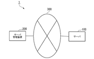
- FIG. 1 is a system configuration diagram showing a system configuration configuration of the server management system 1 according to the first embodiment.
- the server management system 1 includes a server 100 and a server management device 200, and is connected via a network 300. Further, the server management system 1 manages the lamp included in the server 100 from a remote location.
- the network 300 is a wide area communication network such as the Internet.
- the network 300 may be a network using wireless communication or a network using wired communication.
- the network 300 may be configured by combining a plurality of networks.
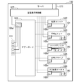
- FIG. 2 is a hardware configuration diagram showing the configuration of the server 100 of the first embodiment.
- the server 100 includes a motherboard 101, a power supply unit 102, a FAN unit 103, a hard disk 104, an optical drive 105, a PCI expansion device 106, a device display control unit 107, and a communication unit 171.
- a device including a lamp is called a unit (functional unit).
- the unit is, for example, a device such as a motherboard 101, a power supply unit 102, a FAN unit 103, a hard disk 104, an optical drive 105, and a PCI expansion device 106.
- Each unit includes a light emission control unit 108.
- the motherboard 101 includes a light emission control unit 108a.
- the power supply unit 102 includes a light emission control unit 108b.
- the FAN unit 103 includes a light emission control unit 108c.
- the hard disk 104 includes a light emission control unit 108d.
- the optical drive 105 includes a light emission control unit 108e.
- the PCI expansion device 106 includes a light emission control unit 108f.
- the light emission control unit 108 will be simply described.
- the light emission control unit 108 is connected to a lamp included in the unit.
- the lamp indicates a status or status regarding the function provided by each unit.
- the light emission control unit 108 outputs the lamp signal generated by each unit to the device display control unit 107. Further, the light emission control unit 108 receives a mode signal related to the light emission state adjustment from the device display control unit 107.
- the light emission control unit 108 controls the light emission state of the connected lamp based on the received mode signal related to the light emission state adjustment.
- the light emission control unit 108 is configured by using, for example, a processor such as a CPU (Central Processing Unit) and an integrated circuit such as a memory.
- a processor such as a CPU (Central Processing Unit)
- an integrated circuit such as a memory.
- the motherboard 101 is configured by using a processor such as a CPU and an integrated circuit such as a memory.
- the motherboard 101 performs arithmetic processing, storage processing, and control processing of the server 100.
- the motherboard 101 controls the power supply unit 102, the FAN unit 103, the hard disk 104, the optical drive 105, and the PCI expansion device 106.
- the motherboard 101 includes a light emission control unit 108a and a device status indicator lamp 111.
- the light emission control unit 108a outputs a lamp signal generated inside the motherboard 101 to the device status display lamp 111.
- the device status display lamp 111 is a lamp that displays the operating status of the server 100.
- the device status indicator lamp 111 is, for example, a light emitting member such as an LED or an organic EL (Electro Luminescence).
- the device status indicator lamp 111 emits light in response to the lamp signal.
- the device status indicator lamp 111 indicates the operating state of the server 100 according to a light emitting state such as changing the color, turning on, turning off, blinking, or changing the amount of light.
- the operating state of the server 100 may be any state as long as it indicates a state related to the operation of the server 100, such as the device status, the power supply status, or the access status of the onboard LAN (Local Area Network).
- the power supply unit 102 receives power from the outside and supplies power to the server 100.
- the power supply unit 102 converts AC power received from the outside into DC power.
- the power supply unit 102 controls to adjust the converted DC power and distribute it to the motherboard 101, the FAN unit 103, the hard disk 104, the optical drive 105, and the PCI expansion device 106.
- the power supply unit 102 includes a light emission control unit 108b and a unit status indicator lamp 121.
- the light emission control unit 108b outputs a lamp signal generated inside the power supply unit 102 to the unit status display lamp 121.
- the unit status display lamp 121 is a lamp that displays the device status of the power supply unit 102.
- the unit status indicator lamp 121 is, for example, a light emitting member such as an LED or an organic EL.
- the unit status indicator lamp 121 emits light in response to a lamp signal.
- the unit status indicator lamp 121 indicates the operating state of the power supply unit 102 depending on the light emitting state such as changing the color, turning on, turning off, blinking, or changing the amount of light.
- the unit status indicator lamp 121 indicates the operating state of the power supply unit 102 by blinking when AC power is supplied, turning on when DC power is supplied, or turning off when none of the power is supplied. ..
- the FAN unit 103 is a unit for cooling devices such as units and devices that make up the server 100.
- the FAN unit 103 is controlled to supply an appropriate air volume by a signal from an external device such as the motherboard 101.
- the FAN unit 103 includes a light emission control unit 108c and a unit status indicator lamp 131.
- the light emission control unit 108c outputs a lamp signal generated inside the FAN unit 103 to the unit status display lamp 131.
- the unit status display lamp 131 is a lamp that displays the device status of the FAN unit 103.
- the unit status indicator lamp 131 is, for example, a light emitting member such as an LED or an organic EL.
- the unit status indicator lamp 131 emits light in response to the lamp signal.
- the unit status display lamp 131 indicates the operating state of the FAN unit 103 according to a light emitting state such as changing the color, turning on, turning off, blinking, or changing the amount of light.
- the unit status indicator lamp 131 lights up when the fan provided in the FAN unit 103 is rotating normally, or blinks when the fan is not rotating normally, thereby indicating the operating state of the FAN unit 103. Shown. Further, a plurality of unit status indicator lamps 131 may be provided depending on the application.
- the hard disk 104 is an auxiliary storage device.
- the hard disk 104 stores data used by the server 100.
- the hard disk 104 includes a light emission control unit 108d and a unit status indicator lamp 141.
- the light emission control unit 108d outputs the lamp signal generated inside the hard disk 104 to the unit status indicator lamp 141.
- the unit status display lamp 141 is a lamp that displays the device status of the hard disk 104.
- the unit status indicator lamp 141 is, for example, a light emitting member such as an LED or an organic EL.
- the unit status indicator lamp 141 emits light in response to a lamp signal.
- the unit status indicator lamp 141 indicates the operating state of the hard disk 104 according to a light emitting state such as changing the color, turning on, turning off, blinking, or changing the amount of light.
- the unit status indicator lamp 141 may be turned on or off depending on the operating state, such as when writing to the hard disk 104, reading data from the hard disk 104, or when an error occurs.
- the operating state of the hard disk 104 is indicated by blinking or changing the amount of light.
- a plurality of unit status indicator lamps 141 may be provided depending on the intended use.
- the optical drive 105 is an optical disk reading device that reads data written on an optical disk such as a CD-ROM (Compact Disc Read Only Memory), a DVD-ROM (Digital Versatile Disc Read Only Memory), or a Blu-Ray Disc.
- the optical drive 105 includes a light emission control unit 108e and a unit status indicator lamp 151.
- the optical drive 105 may be an optical disk writing device that writes data to the optical disk.
- the light emission control unit 108e outputs the lamp signal generated inside the optical drive 105 to the unit status display lamp 151.
- the unit status display lamp 151 is a lamp that displays the device status of the optical drive 105.
- the unit status indicator lamp 151 is, for example, a light emitting member such as an LED or an organic EL.
- the unit status indicator lamp 151 emits light in response to a lamp signal.
- the unit status indicator lamp 151 changes the light emitting state such as changing the color, turning on, turning off, blinking, or changing the amount of light. Therefore, the operating state of the optical drive 105 is shown.
- the unit status indicator lamp 151 may be used when the optical drive 105 is reading data from an optical disc, when the optical drive 105 is writing data to an optical disc, when an error occurs in reading or writing data, and the like.
- the operating state of the optical drive 105 is indicated by turning it on, turning it off, blinking, or changing the amount of light according to the operating state.
- the PCI expansion device 106 is an expansion device connected by a PCI (Peripheral Component Interconnect) bus.
- the PCI expansion device 106 is fitted with a card conforming to the specifications of the PCI expansion device 106 according to the purpose and application.
- the card may be, for example, a graphic accelerator, a disk controller, a network card, or the like.
- the PCI expansion device 106 includes a light emission control unit 108f and a unit status indicator lamp 161.
- the PCI bus may be a device of another standard such as PCI Express.
- the light emission control unit 108f outputs a lamp signal generated inside the PCI expansion device 106 to the unit status display lamp 161.
- the unit status display lamp 161 is a lamp that displays the device status of the PCI expansion device 106.
- the unit status indicator lamp 161 is, for example, a light emitting member such as an LED or an organic EL.
- the unit status indicator lamp 161 emits light in response to a lamp signal.
- the unit status indicator lamp 161 indicates the operating state of the PCI expansion device 106 in response to a change in the light emitting state such as changing the color, turning on, turning off, blinking, or changing the amount of light. For example, a case where a network card is attached to the PCI expansion device 106 will be described.
- the unit status indicator lamp 161 turns on, off, blinks, or changes the amount of light according to the link state with the network and the operating state of the network card such as the amount of traffic in communication. By doing so, the operating state of the PCI expansion device 106 is shown. Further, a plurality of unit status indicator lamps 161 may be provided depending on the application.
- the device display control unit 107 outputs a mode signal related to the light emission state adjustment to each light emission control unit 108.
- the device display control unit 107 receives a lamp signal from the light emission control unit 108.
- the device display control unit 107 transmits the received lamp signal to the server management device 200 via the communication unit 171.
- the device display control unit 107 is configured by using a processor such as a CPU and an integrated circuit such as a memory.
- the mode signal is an aspect of control information.
- the control information is information for controlling the light emitting state of the light emitting member provided in the functional unit.
- the control information is associated with information regarding the light emitting state of the light emitting member.
- the communication unit 171 is a communication device such as a network interface.
- the communication unit 171 is communicably connected to the network 300 by a predetermined protocol.
- the communication unit 171 communicates data with the server management device 200 via the network 300 under the control of the device display control unit 107.
- FIG. 3 is a functional block diagram showing the functional configuration of the unit of the first embodiment.
- the unit 109 corresponds to the motherboard 101, the power supply unit 102, the FAN unit 103, the hard disk 104, the optical drive 105, and the PCI expansion device 106 shown in FIG.
- the unit 109 includes a light emission control unit 108, a status display lamp 191 and a unit main function control unit 192.
- the light emission control unit 108 includes a storage unit 181, an output control unit 182, a signal conversion unit 183, and a communication control unit 184.
- the unit main function control unit 192 includes a lamp signal output unit 193.
- the status display lamp 191 is an aspect of the device status display lamp 111 or the unit status display lamp.
- the unit 109 is an aspect of a functional unit.
- the functional unit is a device that constitutes the server 100.
- the functional unit performs a predetermined function related to its own device.
- the predetermined function may be, for example, power supply or cooling of other functional units.
- the unit main function control unit 192 provides the main functions of the unit 109.
- the unit main function control unit 192 receives power from the outside and supplies power to the server 100.
- the lamp signal output unit 193 generates a lamp signal based on the operating state of the unit main function control unit 192.
- the lamp signal is a signal indicating the on / off or color of the status display lamp 191.
- the lamp signal output unit 193 outputs the generated lamp signal.
- the plurality of wires extending from the lamp signal output unit 193 to the output control unit 182 correspond one-to-one with the status display lamp 191.
- the lamp signal output unit 193 outputs a lamp signal to a predetermined wiring based on the operating state of the unit main function control unit 192.
- the storage unit 181 is configured by using a storage device such as a magnetic hard disk device or a semiconductor storage device.
- the storage unit 181 stores the unit identification information.
- the unit identification information is information that uniquely identifies the unit 109 provided in the server 100.
- the unit identification information may be configured by using a plurality of letters and numbers.
- the unit identification information may be any information as long as it is different from the other units 109 provided in the server 100.
- the unit identification information is stored in the storage unit 181 in advance.
- the unit identification information is an aspect of the identification information.
- the identification information is information that uniquely identifies the functional unit.
- the output control unit 182 is connected to the status display lamp 191.
- the output control unit 182 adjusts the light emitting state of the status display lamp 191.
- the output control unit 182 receives the lamp signal from the lamp signal output unit 193.
- the output control unit 182 receives a mode signal from the communication control unit 184.
- the output control unit 182 adjusts the output current output to the status display lamp 191 based on the lamp signal and the mode signal.
- the output control unit 182 adjusts the light emitting state by outputting the adjusted output current to the status display lamp 191.
- the mode signal is a signal that determines the light emitting state of the status display lamp 191.
- the mode signal may have a plurality of types such as extinguishing, dimming, normal or enhancing (change in light intensity).
- the output current may be associated with the type of mode signal.
- the output current may be, for example, 0% when the light is turned off, 20% when the light is reduced, 50% when the light is turned off, and 80% when the light is emphasized, and is not limited thereto.
- the output control unit 182 may hold in advance a table in which the output current and the type of the mode signal are associated with each other.
- the status indicator lamp 191 is one aspect of the light emitting member.
- the light emitting member is provided in the functional unit.
- the light emitting member is a lamp that displays the status of the functional unit.
- the light emitting member is, for example, an LED or an organic EL.
- the signal conversion unit 183 receives the lamp signal output by the lamp signal output unit 193.
- the signal conversion unit 183 generates lamp display information based on the received lamp signal.
- the lamp display information is information indicating a state relating to lighting or extinguishing of the status display lamp 191.
- the lamp display information may be represented by a binary value such as 0 or 1.
- the lamp display information may indicate, for example, if it is 0, it is turned off, and if it is 1, it is turned on.
- the signal conversion unit 183 may determine the lamp display information to 0 or 1 according to the signal strength of the received lamp signal.
- the signal conversion unit 183 may generate a plurality of lamp display information according to the length of time that the lamp signal is received.
- the signal conversion unit 183 compresses the lamp display information generated from the lamp signal.
- the signal conversion unit 183 may compress the generated lamp display information by sampling it.
- the signal conversion unit 183 acquires unit identification information from the storage unit 181.
- the signal conversion unit 183 associates the compressed lamp display information with the acquired unit identification information and outputs the compressed lamp display information to the communication control unit 184.
- the lamp display information is an aspect of the display information.
- the display information is information for displaying the light emitting state of the light emitting member generated by the functional unit on another device.
- the communication control unit 184 is connected to the device display control unit 107.
- the communication control unit 184 receives information in which the lamp display information and the unit identification information are associated with each other from the signal conversion unit 183.
- the communication control unit 184 acquires the information in which the lamp display information and the unit identification information are associated with each other, the communication control unit 184 outputs the acquired information to the device display control unit 107. Further, the communication control unit 184 receives a mode signal from the device display control unit 107. The communication control unit 184 outputs the received mode signal to the output control unit 182.
- the device display control unit 107 receives information in which the mode signal and the unit identification information are associated with each other from the server management device 200 via the communication unit 171.
- the device display control unit 107 outputs a mode signal to the unit identified by the unit identification information.
- FIG. 4 is a functional block diagram showing a functional configuration of the server management device 200 of the first embodiment.
- the server management device 200 is configured by using an information processing device such as a personal computer, a smart device, or a tablet computer.
- the server management device 200 includes a communication unit 201, an input unit 202, an output unit 203, and a control unit 204.
- the communication unit 201 is a communication device such as a network interface.
- the communication unit 201 is communicably connected to the network 300 using a predetermined protocol.
- the communication unit 201 communicates data with another device via the network 300 under the control of the control unit 204.
- the input unit 202 is configured by using an existing input device such as a keyboard, a pointing device (mouse, tablet, etc.), a button, and a touch panel.
- the input unit 202 is operated when inputting an instruction from the user of the server management device 200 to the server management device 200.
- the input unit 202 may be an interface for connecting the input device to the server management device 200.
- the input unit 202 inputs the input signal generated in response to the user input of the server management device 200 to the server management device 200 in the input device.
- the user of the server management device 200 may be, for example, a person who suppresses the power consumption of the server 100 or a person who monitors and controls the server 100.
- the user of the server management device 200 may be any person who manages the server 100.
- the output unit 203 outputs data to the user of the server management device 200 via an output device (not shown) connected to the server management device 200.
- the output device may be configured by using, for example, a device that outputs an image or characters to the screen.
- the output device can be configured by using a CRT (CathodeRayTube), a liquid crystal display, an organic EL display, or the like.
- the output device may be configured by using a device that prints (prints) an image or characters on a sheet.
- the output device can be configured by using an inkjet printer, a laser printer, or the like.
- the output device may be configured by using a device that converts characters into voice and outputs the characters.
- the output device can be configured by using a voice synthesizer and a voice output device (speaker).
- the output device may be configured by using a light emitting device such as an LED.
- the output unit 203 may transmit the determination result to another information processing device via the communication device provided in the server management device 200.
- the control unit 204 is configured by using a processor such as a CPU and a memory.
- the control unit 204 functions as the server management unit 241 when the processor executes a specific program.
- the server management unit 241 communicates with the server 100 by executing a predetermined server management program. For example, the server management unit 241 transmits a mode signal to the server 100. For example, the server management unit 241 receives information in which the lamp display information and the unit identification information are associated with each other from the server 100. First, a case where the server management device 200 transmits a mode signal to the server 100 will be described.
- the server management unit 241 outputs the lighting state of the device status display lamp or the unit status display lamp provided in the server 100 to the output unit 203.
- the user of the server management device 200 operates the input unit 202 based on the lighting state output to the output unit 203.
- the user of the server management device 200 inputs the mode signal and the unit identification information to the server management device 200 by operating the input unit 202.
- the input mode signal is any one of a plurality of types of mode signals such as extinguishing, dimming, normal or enhancing (change in light intensity).
- the unit identification information to be input is the unit identification information of any one of the units provided in the server 100 such as the motherboard 101, the power supply unit 102, the FAN unit 103, the hard disk 104, the optical drive 105, or the PCI expansion device 106. ..
- the server management unit 241 associates the input mode signal with the unit identification information and transmits the unit identification information to the server 100 via the communication unit 201.
- the unit identification information to be input may be two or more. In this case, the server management unit 241 may be configured to associate the input plurality of unit identification information with the mode signal and transmit the mode signal to the server 100.
- the server management unit 241 receives information in which the lamp display information and the unit identification information are associated with each other from the server 100 via the communication unit 201.
- the server management unit 241 generates a management screen based on the lamp display information and the unit identification information.
- the management screen is a screen showing the lighting state of the lamp provided on the server 100. For example, the case where the server management unit 241 receives the information associated with the lighting as the lamp display information and the power supply unit 102 as the unit identification information will be described.
- the server management unit 241 generates a management screen indicating a state in which the status display lamp 191 provided in the unit 109 is lit.
- the server management unit 241 outputs the generated management screen to the output unit 203.
- the output unit 203 outputs the output management screen.
- the display state of the state display lamp 191 output as the management screen does not depend on the mode signal. For example, even when the extinguishing state is input as the mode signal, when the lamp display information indicates lighting, the output unit 203 outputs a management screen indicating lighting of the lighting state of the status display lamp 191.
- FIG. 5 is a sequence chart showing a specific example of the flow of processing for controlling the light emission of the status display lamp of the first embodiment.
- the sequence chart shown in FIG. 5 is executed when a mode signal is input from the user of the server management device 200.
- the output unit 203 of the server management device 200 outputs the management screen.
- the user of the server management device 200 operates the input unit 202 based on the management screen output to the output unit 203.
- the input unit 202 receives a mode signal from the user based on the operation (step S101).
- the input unit 202 receives the unit identification information together with the mode signal.
- the server management unit 241 associates the input mode signal with the unit identification information and transmits the unit identification information to the server 100 via the communication unit 201 (step S102).
- the device display control unit 107 of the server 100 receives information in which the mode signal and the unit identification information are associated with each other.
- the device display control unit 107 determines the unit 109 that outputs the received mode signal (step S103). Specifically, the device display control unit 107 determines to output a mode signal to the unit 109 identified by the unit identification information.
- the output control unit 182 controls the output current based on the mode signal (step S104). Specifically, the output control unit 182 controls the output current to the output current associated with the received mode signal.
- the unit status indicator lamp emits light in a light emitting state corresponding to the controlled output current and the lamp signal generated by the lamp signal output unit 193 (step S104).
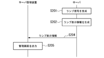
- FIG. 6 is a sequence chart showing a specific example of the flow of processing for displaying the lighting state of the status display lamp of the first embodiment.
- the sequence chart shown in FIG. 6 is executed when the lamp signal is generated by the server 100.
- the lamp signal output unit 193 generates a lamp signal based on the operating state of the unit main function control unit 192 (step S201).
- the signal conversion unit 183 receives the lamp signal output by the lamp signal output unit 193.
- the signal conversion unit 183 generates lamp display information based on the received lamp signal (step S202). Specifically, the signal conversion unit 183 determines the lamp display information to be 0 or 1 according to the signal strength of the received lamp signal.
- the signal conversion unit 183 compresses the generated lamp display information by sampling it.
- the signal conversion unit 183 acquires unit identification information from the storage unit 181.
- the signal conversion unit 183 associates the compressed lamp display information with the acquired unit identification information and outputs the compressed lamp display information to the communication control unit 184.
- the communication control unit 184 receives information in which the lamp display information and the unit identification information are associated with each other from the signal conversion unit 183.
- the communication control unit 184 acquires the information in which the lamp display information and the unit identification information are associated with each other, the communication control unit 184 outputs the acquired information to the device display control unit 107.
- the device display control unit 107 transmits information in which the lamp display information and the unit identification information are associated with each other to the server management device 200 (step S203).
- the server management unit 241 of the server management device 200 generates a management screen for displaying the lighting state of the lamp based on the lamp display information and the unit identification information.
- the output unit 203 outputs the generated management screen (step S205).
- the unit 109 includes a light emission control unit 108.
- the unit 109 is a device included in the server 100 such as the motherboard 101, the power supply unit 102, the FAN unit 103, the hard disk 104, the optical drive 105, and the PCI expansion device 106.
- the server 100 receives a mode signal that determines the state of light emission of the lamp.
- the light emission control unit 108 adjusts the light emission state of the lamp by controlling the current of the lamp according to the mode signal. Therefore, the server management system 1 can control the light emitting state of the lamp from a remote location. Therefore, the server 100 can suppress the power consumption of the server 100 by receiving the mode signal related to turning off or reducing the light.
- the server 100 receives the information in which the unit identification information for identifying the unit provided in the server 100 and the mode signal are associated with each other. With this configuration, it is possible to control the light emitting state of the lamp for each unit included in the server 100. Therefore, the server management device 200 can integrate the lamps included in the server 100 for each unit and control them from a remote location.
- the server 100 transmits the lamp display information and the unit identification information in association with each other to the server management device 200.
- the output unit 203 of the server management device 200 outputs a management screen generated based on the lamp display information and the unit identification information.
- the management screen displays the lighting status of the lamp.
- the server management device 200 can aggregate and output the lamps included in the server 100. Therefore, the status of all the lamps provided in the server 100 can be remotely monitored. Further, even when the lamp included in the server 100 is turned off, the state of the server 100 can be monitored from a remote location. Therefore, it is possible to suppress the power consumption of the server 100.
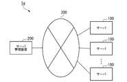
- FIG. 7 is a system configuration diagram showing a system configuration configuration of the server management system 1a according to the second embodiment.
- the server management system 1a in the second embodiment is different from the first embodiment in that it includes a plurality of servers 100, but the other configurations are the same.
- the points different from the first embodiment will be described.
- the server management system 1a in the second embodiment includes a plurality of servers 100.
- the server management device 200 of the server management system 1a aggregates the information of the server 100 via the network 300 in an environment in which a plurality of servers 100 are installed.
- An environment in which a plurality of servers 100 are installed is, for example, a server room or a data center.
- the server management device 200 controls the lamp with respect to the server 100 in the same procedure as in the first embodiment.
- the servers 100 When a plurality of servers 100 are installed in a server room or a data center, the servers 100 may be installed in the same rack at high density without gaps.
- the server 100 is operated for various reasons such as a failure or maintenance timing.
- a maintenance person enters a place such as a server room or a data center.
- the maintenance staff finds the server to be operated, finds the parts to be replaced of the server, and the adjacent similar products. It was difficult to distinguish them.
- Such installation has caused operational mistakes and identification mistakes by maintenance personnel, and has caused a decrease in work efficiency.
- FIG. 8 is a sequence chart showing the flow of maintenance for the server 100 according to the second embodiment.
- the sequence chart shown in FIG. 8 is executed when a maintenance person performs maintenance work on the server 100.
- the maintenance work is, for example, resolving a failure that has occurred in the server 100, periodic maintenance, or the like.
- the input unit 202 of the server management device 200 receives the mode signal based on the operation from the user of the server management device 200 (step S301).
- the input unit 202 accepts the extinguishing mode as a mode signal.
- the input unit 202 may receive the unit identification information together with the mode signal.
- the input unit 202 receives the unit identification information of the unit included in all the servers 100 connected to the network 300.
- the server management unit 241 of the server management device 200 associates the input extinguishing mode (mode signal) with the unit identification information and transmits the unit identification information to all the servers 100 via the communication unit 201 (step S302).
- Each server 100 turns off the lamp (step S303). Specifically, the device display control unit 107 of the server 100 receives information in which the mode signal and the unit identification information are associated with each other. The device display control unit 107 outputs a mode signal to all the units. The output control unit 182 turns off the lamp by controlling the unit output current based on the mode signal.
- the input unit 202 receives the mode signal based on the operation from the user of the server management device 200 (step S304).
- the input unit 202 accepts the lighting mode as a mode signal.
- the input unit 202 receives the unit identification information together with the mode signal.
- the input unit 202 receives the unit identification information regarding the unit included in the server 100 to be maintained.
- the input unit 202 may accept only the unit identification information regarding the unit to be maintained.
- the input unit 202 may receive different mode signals for the unit to be maintained. For example, a mode signal such as a dimming mode signal or a light-off mode may be received by a unit other than the unit to be maintained.
- the server management unit 241 associates the input lighting mode (mode signal) with the unit identification information and transmits the unit identification information to the maintenance target server 100 via the communication unit 201 (step S305).
- the server 100 to be maintained turns on the lamp (step S306).
- the device display control unit 107 receives information in which the mode signal and the unit identification information are associated with each other.
- the device display control unit 107 outputs a mode signal to the unit identified by the unit identification information.
- the output control unit 182 lights the lamp by controlling the unit output current based on the mode signal.
- the server management system 1a can turn on the lamp only for the server 100 to be maintained.
- the server 100 accepts different lighting modes (for example, dimming mode or extinguishing mode) for the unit to be maintained, the unit to be maintained can be made conspicuous.
- the maintenance staff can more easily identify the server 100 to be maintained and perform the maintenance work.
- the input unit 202 receives the mode signal based on the operation from the user of the server management device 200 (step S307).
- the input unit 202 accepts the lighting mode as a mode signal.
- the input unit 202 receives the unit identification information together with the mode signal.
- the input unit 202 receives the unit identification information of the unit included in the server 100 other than the maintenance target server 100 connected to the network 300.
- the server management unit 241 associates the input lighting mode (mode signal) with the unit identification information and transmits the unit identification information to a server 100 other than the maintenance target server 100 via the communication unit 201 (step S308).
- the server 100 turns on the lamp (step S309).
- the device display control unit 107 of the server 100 receives information in which the mode signal and the unit identification information are associated with each other.
- the device display control unit 107 outputs a mode signal to all the units.
- the output control unit 182 lights the lamp by controlling the unit output current based on the mode signal.
- the server management system 1a configured in this way, it is possible to control the status display lamp 191 for a plurality of servers 100 from a remote location. Therefore, when performing maintenance work on the server 100, it is possible to light only the server 100 to be maintained from a remote location. Therefore, even when the servers 100 are installed in the same rack at high density without gaps in a server room, data center, or the like, the server 100 to be worked can be easily found and the work efficiency can be improved. Can be done.
- the server management device 200 included in the server management system 1a allows the lighting status of the status display lamps 191 of a plurality of servers 100 to be confirmed from a remote location. Further, the server management device 200 can turn on the status display lamp 191 from a remote location as needed. Therefore, it is not necessary to keep the status indicator lamp 191 on at all times in the server room or data center where entry is restricted from the viewpoint of security.
- the status indicator lamp 191 of the server 100 installed in the server room or the data center is turned off during normal operation. This makes it possible for the server 100 to suppress power consumption.
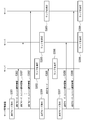
- FIG. 9 is an explanatory diagram showing the minimum configuration of the server 10 according to the present invention.
- the server 10 shown in FIG. 9 includes a communication unit 11 and a light emission control unit 12. With such a configuration, the communication unit 11 communicates with other devices via the network.
- the light emission control unit 12 is provided in the functional unit that constitutes the own device and identifies one or more functional units that perform a predetermined function related to the own device, and the functional unit acquired via the communication unit. Based on the control information for controlling the light emitting state of the light emitting member, the light emitting state of the light emitting member provided in the functional unit identified by the identification information is controlled.
- the server 10 can control the light emitting state of the light emitting member provided on the server 10 from a remote location. Therefore, when it is not necessary, the server 10 can be further reduced in power consumption by turning off the lamp, reducing the light, and the like.
- the mode signal is controlled for each unit, but the mode signal is not limited to this.
- the server management device 200 may be configured to control the lighting state for each lamp.
- the input unit 202 further receives the input of the lamp identification information in addition to the mode signal and the unit identification information.
- the lamp identification information is information that can uniquely identify the lamp provided in the unit.
- the output control unit 182 controls the output current for the lamp identified by the lamp identification information.
- the server management device 200 can control the lamp in more detail. Therefore, the server management system can suppress the power consumption of the server 100.
- the lamp identification information is an aspect of the light emitting member identification information.
- the light emitting member identification information uniquely identifies the light emitting member provided in the functional unit.
- the above-mentioned server 100 and server management device 200 have a computer system inside.
- the process of controlling the light emitting state of the lamp and remote monitoring described above is stored in a computer-readable recording medium in the form of a program, and the above processing is performed by the computer reading and executing this program.
- the computer-readable recording medium refers to a magnetic disk, a magneto-optical disk, a CD-ROM, a DVD-ROM, a semiconductor memory, or the like.
- this computer program may be distributed to a computer via a communication line, and the computer receiving the distribution may execute the program.
- a program for realizing the functions of the device display control unit 107 and the light emission control unit 108 in FIG. 3 and the functions of the control unit 204 in FIG. 4 is recorded on a computer-readable recording medium and recorded on the recording medium.
- the function of the device display control unit 107 and the light emission control unit 108 in FIG. 3 and the function of the control unit 204 in FIG. 4 may be realized by loading the program into a computer system and executing the program.
- the term "computer system” as used herein includes hardware such as an OS and peripheral devices. Further, the "computer system” shall also include a WWW system provided with a homepage providing environment (or display environment).
- the "computer-readable recording medium” refers to a portable medium such as a flexible disk, a magneto-optical disk, a ROM, or a CD-ROM, or a storage device such as a hard disk built in a computer system.
- a "computer-readable recording medium” is a volatile memory (RAM) inside a computer system that serves as a server or client when a program is transmitted via a network such as the Internet or a communication line such as a telephone line. In addition, it shall include those that hold the program for a certain period of time.
- the above program may be transmitted from a computer system in which this program is stored in a storage device or the like to another computer system via a transmission medium or by a transmission wave in the transmission medium.
- the "transmission medium” for transmitting a program refers to a medium having a function of transmitting information, such as a network (communication network) such as the Internet or a communication line (communication line) such as a telephone line.
- the above program may be for realizing a part of the above-mentioned functions.
- a so-called difference file (difference program) may be used, which can realize the above-mentioned functions in combination with a program already recorded in the computer system.
- the present invention relates to a server and a server management method applied to a server management system.
- Server management system 10 100 Server 101 Motherboard 102 Power supply unit 103 FAN unit 104 Hard disk 105 Optical drive 106 PCI expansion device 107 Device display control unit 12, 108 Light emission control unit 109 Unit 111 Device status indicator lamp 121, 131, 141, 151 , 161 Unit status indicator lamps 11, 171 and 201 Communication unit 181 Storage unit 182 Output control unit 183 Signal conversion unit 184 Communication control unit 191 Status display lamp 192 Unit main function control unit 193 Lamp signal output unit 200 Server management device 202 Input unit 203 Output unit 204 Control unit 241 Server management unit 300 Network
Landscapes
- Engineering & Computer Science (AREA)
- Theoretical Computer Science (AREA)
- Computer Networks & Wireless Communication (AREA)
- General Engineering & Computer Science (AREA)
- Signal Processing (AREA)
- Physics & Mathematics (AREA)
- General Physics & Mathematics (AREA)
- Data Mining & Analysis (AREA)
- Computing Systems (AREA)
- Computer Hardware Design (AREA)
- Circuit Arrangement For Electric Light Sources In General (AREA)
- Power Sources (AREA)
- Selective Calling Equipment (AREA)
Abstract
サーバが、ネットワークを介して他の装置と通信する通信手段と、所定の機能を実行する1つ以上の機能ユニットを識別する識別情報と通信手段を介して取得された機能ユニットに設けられた発光部材の発光状態とを制御する制御情報とに基づいて、識別情報によって識別される機能ユニットに設けられた発光部材の発光状態を制御する発光制御手段とを備える。
Description
本発明は、サーバ、サーバ管理システム、サーバ管理方法及びサーバ管理プログラムに関する。
近年、データセンターにおいても環境を重視した運営が求められている。このため、データセンターに設置されているサーバについても消費電力量を抑制することが求められている。例えば、サーバに所定の操作を行うことでサーバに設けられたランプを消灯し、消費電力量を抑制できる技術が特許文献1に開示されている。しかし、ランプの役割は、サーバの状態表示や個体識別表示を行うことである。このため、ランプを消灯してサーバを運用することは難しい。
また、サーバは、遠隔地から監視や制御することが行われている。このようなサーバに設けられたランプであれば、ランプを消灯してサーバを運用することもできる。例えば、遠隔地からサーバを制御することができる技術が、特許文献2に開示されている。また、遠隔地からサーバのLED(Light Emitting Diode)の表示を確認することができる技術が、特許文献3に開示されている。また、LEDの光量を制御することができる技術が特許文献4及び5に開示されている。しかし、サーバには、遠隔地から監視制御することができないランプがある。このようなランプについては、依然としてランプを点灯した状態を維持しておく必要があった。
また、サーバは、遠隔地から監視や制御することが行われている。このようなサーバに設けられたランプであれば、ランプを消灯してサーバを運用することもできる。例えば、遠隔地からサーバを制御することができる技術が、特許文献2に開示されている。また、遠隔地からサーバのLED(Light Emitting Diode)の表示を確認することができる技術が、特許文献3に開示されている。また、LEDの光量を制御することができる技術が特許文献4及び5に開示されている。しかし、サーバには、遠隔地から監視制御することができないランプがある。このようなランプについては、依然としてランプを点灯した状態を維持しておく必要があった。
特許文献1に記載された技術では、遠隔地からサーバのランプを消灯することで消費電力量を抑制することはできない。また、特許文献2に記載された技術は、遠隔地からサーバを制御することができるものの、ランプの制御を行うものではない。また、特許文献3に記載された技術は、ランプの表示を確認できることにとどまり、ランプの制御を行うものではない。また、特許文献4及び5に記載された技術は、装置の前面に立ったユーザに対してストレスを与えないように光量を制御するための技術であり、サーバの省電力制御を行うものではない。
このように、遠隔地からサーバに設けられたランプの発光状態を制御する技術は存在しない。
このように、遠隔地からサーバに設けられたランプの発光状態を制御する技術は存在しない。
そこでこの発明は、上述の課題を解決するサーバ、サーバ管理システム、サーバ管理方法及びプログラムを提供することを目的としている。
本発明の第1の態様によるサーバは、ネットワークを介して他の装置と通信する通信手段と、所定の機能を実行する1つ以上の機能ユニットを識別する識別情報と前記通信手段を介して取得された前記機能ユニットに設けられた発光部材の発光状態とを制御する制御情報とに基づいて、前記識別情報によって識別される機能ユニットに設けられた発光部材の発光状態を制御する発光制御手段とを備える。
また、本発明の第2の態様によるサーバ管理システムは、ネットワークに接続されたサーバ管理装置と、前記ネットワークを介して前記サーバ管理装置と通信する通信手段と所定の機能を実行する1つ以上の機能ユニットを識別する識別情報と前記通信部を介して取得された前記機能ユニットに設けられた発光部材の発光状態とを制御する制御情報とに基づいて前記識別情報によって識別される機能ユニットに設けられた発光部材の発光状態を制御する発光制御手段とを有するサーバとを備える。
また、本発明の第3の態様によるサーバ管理方法は、ネットワークを介して他の装置と通信し、所定の機能を実行する1つ以上の機能ユニットを識別する識別情報と前記通信ステップにおいて取得された前記機能ユニットに設けられた発光部材の発光状態とを制御する制御情報とに基づいて、前記識別情報によって識別される機能ユニットに設けられた発光部材の発光状態を制御する。
また、本発明の第4の態様によるサーバ管理プログラムは、コンピュータに、ネットワークを介して他の装置と通信させ、サーバに関する所定の機能を実行する1つ以上の機能ユニットを識別する識別情報と前記通信ステップにおいて取得された前記機能ユニットに設けられた発光部材の発光状態とを制御する制御情報とに基づいて、前記識別情報によって識別される機能ユニットに設けられた発光部材の発光状態を制御させる。
本発明によれば、遠隔地からサーバの消費電力を抑制することができるという効果が得られる。
(第一実施形態)
以下、本発明の第一実施形態によるサーバ管理システム1を図面を参照して説明する。
図1は、第一実施形態によるサーバ管理システム1のシステム構成構成を示すシステム構成図である。サーバ管理システム1は、サーバ100と、サーバ管理装置200と、を備え、ネットワーク300を介して接続される。また、サーバ管理システム1は、サーバ100が備えるランプを遠隔地から管理する。
以下、本発明の第一実施形態によるサーバ管理システム1を図面を参照して説明する。
図1は、第一実施形態によるサーバ管理システム1のシステム構成構成を示すシステム構成図である。サーバ管理システム1は、サーバ100と、サーバ管理装置200と、を備え、ネットワーク300を介して接続される。また、サーバ管理システム1は、サーバ100が備えるランプを遠隔地から管理する。
サーバ100及びサーバ管理装置200は、いずれもネットワーク300を介して通信可能である。ネットワーク300は、例えばインターネット等の広域通信網である。ネットワーク300は、無線通信を用いたネットワークであってもよいし、有線通信を用いたネットワークであってもよい。ネットワーク300は、複数のネットワークが組み合わされて構成されてもよい。
図2は、第一実施形態のサーバ100の構成を示したハードウェア構成図である。サーバ100は、マザーボード101、電源ユニット102、FANユニット103、ハードディスク104、光学ドライブ105、PCI拡張デバイス106、装置表示制御部107及び通信部171を備える。本実施形態では、ランプを備える装置をユニット(機能ユニット)と呼ぶ。
ユニットは、例えばマザーボード101、電源ユニット102、FANユニット103、ハードディスク104、光学ドライブ105及びPCI拡張デバイス106等の機器である。ユニットは、それぞれ発光制御部108を備える。例えば、マザーボード101は、発光制御部108aを備える。例えば、電源ユニット102は、発光制御部108bを備える。例えば、FANユニット103は、発光制御部108cを備える。例えば、ハードディスク104は、発光制御部108dを備える。例えば、光学ドライブ105は、発光制御部108eを備える。例えば、PCI拡張デバイス106は、発光制御部108fを備える。以下、いずれのユニットに設けられた発光制御部108であるかを区別しない場合は、単に発光制御部108として説明する。
ユニットは、例えばマザーボード101、電源ユニット102、FANユニット103、ハードディスク104、光学ドライブ105及びPCI拡張デバイス106等の機器である。ユニットは、それぞれ発光制御部108を備える。例えば、マザーボード101は、発光制御部108aを備える。例えば、電源ユニット102は、発光制御部108bを備える。例えば、FANユニット103は、発光制御部108cを備える。例えば、ハードディスク104は、発光制御部108dを備える。例えば、光学ドライブ105は、発光制御部108eを備える。例えば、PCI拡張デバイス106は、発光制御部108fを備える。以下、いずれのユニットに設けられた発光制御部108であるかを区別しない場合は、単に発光制御部108として説明する。
発光制御部108は、ユニットが備えるランプと接続される。ランプは、それぞれのユニットが提供する機能に関する状態又は状況を示す。発光制御部108は、それぞれのユニットで生成されたランプ信号を装置表示制御部107に出力する。また、発光制御部108は、装置表示制御部107から発光状態調整に関するモード信号を受信する。発光制御部108は、受信した発光状態調整に関するモード信号に基づいて、接続されたランプの発光状態を制御する。発光制御部108は、例えば、CPU(Central Processing Unit)等のプロセッサとメモリ等の集積回路を用いて構成される。
マザーボード101は、CPU等のプロセッサとメモリ等の集積回路を用いて構成される。マザーボード101は、サーバ100の演算処理、記憶処理及び制御処理を行う。具体的には、マザーボード101は、電源ユニット102、FANユニット103、ハードディスク104、光学ドライブ105及びPCI拡張デバイス106を制御する。マザーボード101は、発光制御部108aと装置状態表示ランプ111とを備える。
発光制御部108aは、マザーボード101内部で生成されるランプ信号を装置状態表示ランプ111に出力する。装置状態表示ランプ111は、サーバ100の動作状態を表示するランプである。装置状態表示ランプ111は、例えば、LED又は有機EL(Electro Luminescence)等の発光部材である。装置状態表示ランプ111は、ランプ信号に応じて発光する。装置状態表示ランプ111は、色を変えたり、点灯したり、消灯したり、点滅したり、光量を変化したりする等の発光状態によって、サーバ100の動作状態を示す。サーバ100の動作状態は、例えば、装置ステータス、給電状況又はオンボードLAN(Local Area Network)のアクセス状況等のサーバ100の動作に関する状態を示すのであればどのような状態を示してもよい。
電源ユニット102は、外部から電源を受けサーバ100に電力を供給する。電源ユニット102は、外部から受けた交流電力を直流電力に変換する。電源ユニット102は、変換された直流電力を調整し、マザーボード101、FANユニット103、ハードディスク104、光学ドライブ105及びPCI拡張デバイス106に分配する制御を行う。電源ユニット102は、発光制御部108bとユニット状態表示ランプ121とを備える。
発光制御部108bは、電源ユニット102内部で生成されるランプ信号をユニット状態表示ランプ121に出力する。ユニット状態表示ランプ121は、電源ユニット102の装置状態を表示するランプである。ユニット状態表示ランプ121は、例えば、LED又は有機EL等の発光部材である。ユニット状態表示ランプ121は、ランプ信号に応じて発光する。ユニット状態表示ランプ121は、色を変えたり、点灯したり、消灯したり、点滅したり、光量を変化したりする等の発光状態によって、電源ユニット102の動作状態を示す。例えば、ユニット状態表示ランプ121は、AC電力供給時には点滅したり、DC電力供給時には点灯したり、いずれの電力も供給されない場合には消灯したり、することで、電源ユニット102の動作状態を示す。
FANユニット103は、サーバ100を構成するユニット及びデバイス等の機器を冷却するためのユニットである。FANユニット103は、マザーボード101等の外部の機器からの信号によって適切な風量を供給するよう制御される。FANユニット103は、発光制御部108cとユニット状態表示ランプ131とを備える。
発光制御部108cは、FANユニット103内部で生成されるランプ信号をユニット状態表示ランプ131に出力する。ユニット状態表示ランプ131は、FANユニット103の装置状態を表示するランプである。ユニット状態表示ランプ131は、例えば、LED又は有機EL等の発光部材である。ユニット状態表示ランプ131は、ランプ信号に応じて発光する。ユニット状態表示ランプ131は、色を変えたり、点灯したり、消灯したり、点滅したり、光量を変化したりする等の発光状態によって、FANユニット103の動作状態を示す。例えば、ユニット状態表示ランプ131は、FANユニット103に設けられたファンが正常に回転している時には点灯したり、正常に回転していない時には点滅したり、することでFANユニット103の動作状態を示す。また、ユニット状態表示ランプ131は、用途に応じて複数備えられてもよい。
ハードディスク104は、補助記憶装置である。ハードディスク104は、サーバ100によって使用されるデータが格納される。ハードディスク104は、発光制御部108dとユニット状態表示ランプ141とを備える。
発光制御部108dは、ハードディスク104内部で生成されるランプ信号をユニット状態表示ランプ141に出力する。ユニット状態表示ランプ141は、ハードディスク104の装置状態を表示するランプである。ユニット状態表示ランプ141は、例えば、LED又は有機EL等の発光部材である。ユニット状態表示ランプ141は、ランプ信号に応じて発光する。ユニット状態表示ランプ141は、色を変えたり、点灯したり、消灯したり、点滅したり、光量を変化したりする等の発光状態によって、ハードディスク104の動作状態を示す。例えば、ユニット状態表示ランプ141は、ハードディスク104に書き込みされている時、ハードディスク104からデータを読み取りされている時、エラーが発生した時等の、動作状態に応じて、点灯したり、消灯したり、点滅したり、光量を変化したりすることでハードディスク104、の動作状態を示す。また、ユニット状態表示ランプ141は、用途に応じて複数備えられてもよい。
光学ドライブ105は、CD-ROM(Compact Disc Read Only Memory)、DVD-ROM(Digital Versatile Disc Read Only Memory)又はBlu-RayDisc等の光ディスクに書き込まれたデータを読み取る光ディスク読取装置である。光学ドライブ105は、発光制御部108eとユニット状態表示ランプ151とを備える。なお、光学ドライブ105は、光ディスクにデータを書き込む光ディスク書込装置であってもよい。
発光制御部108eは、光学ドライブ105内部で生成されるランプ信号をユニット状態表示ランプ151に出力する。ユニット状態表示ランプ151は、光学ドライブ105の装置状態を表示するランプである。ユニット状態表示ランプ151は、例えば、LED又は有機EL等の発光部材である。ユニット状態表示ランプ151は、ランプ信号に応じて発光するユニット状態表示ランプ151は、色を変えたり、点灯したり、消灯したり、点滅したり、光量を変化したりする等の発光状態の変化よって、光学ドライブ105の動作状態を示す。例えば、ユニット状態表示ランプ151は、光学ドライブ105が光ディスクからデータを読み取りしている時、光学ドライブ105が光ディスクにデータを書き込みしている時、データの読み取り又は書き込みにエラーが発生した時等の、動作状態に応じて、点灯したり、消灯したり、点滅したり、光量を変化したりすることで光学ドライブ105の動作状態を示す。
PCI拡張デバイス106は、PCI(Peripheral Component Interconnect)バスで接続される拡張デバイスである。PCI拡張デバイス106は、目的及び用途に応じて、PCI拡張デバイス106の仕様に準拠したカードを取り付けされる。カードは、例えばグラフィックアクセラレータ、ディスクコントローラ又はネットワークカード等であってもよい。PCI拡張デバイス106は、発光制御部108fとユニット状態表示ランプ161とを備える。なお、なお、PCIバスは、PCIExpress等の他の規格のデバイスであってもよい。
発光制御部108fは、PCI拡張デバイス106内部で生成されるランプ信号をユニット状態表示ランプ161に出力する。ユニット状態表示ランプ161は、PCI拡張デバイス106の装置状態を表示するランプである。ユニット状態表示ランプ161は、例えば、LED又は有機EL等の発光部材である。ユニット状態表示ランプ161は、ランプ信号に応じて発光する。ユニット状態表示ランプ161は、色を変えたり、点灯したり、消灯したり、点滅したり、光量を変化したりする等の発光状態の変化に応じて、PCI拡張デバイス106の動作状態を示す。例えば、PCI拡張デバイス106にネットワークカードが取り付けされた場合について説明する。この場合、ユニット状態表示ランプ161は、ネットワークとのリンク状態や、通信におけるトラフィック量等のネットワークカードの動作状態に応じて、点灯したり、消灯したり、点滅したり、、光量を変化したりすることでPCI拡張デバイス106の動作状態を示す。また、ユニット状態表示ランプ161は、用途に応じて複数備えられてもよい。
装置表示制御部107は、各発光制御部108に対して発光状態調整に関するモード信号を出力する。装置表示制御部107は、発光制御部108からランプ信号を受信する。装置表示制御部107は、受信したランプ信号を通信部171を介してサーバ管理装置200に送信する。装置表示制御部107は、CPU等のプロセッサとメモリ等の集積回路を用いて構成される。モード信号は、制御情報の一態様である。制御情報は、機能ユニットに設けられた発光部材の発光状態とを制御するための情報である。制御情報は、発光部材の発光状態に関する情報に対応付けられる。
通信部171は、ネットワークインターフェース等の通信装置である。通信部171は、所定のプロトコルでネットワーク300に通信可能に接続する。通信部171は、装置表示制御部107の制御に応じてネットワーク300を介してサーバ管理装置200との間でデータ通信する。
図3は、第一実施形態のユニットの機能構成を示した機能ブロック図である。ユニット109は、図2で示したマザーボード101、電源ユニット102、FANユニット103、ハードディスク104、光学ドライブ105及びPCI拡張デバイス106に相当する。ユニット109は、発光制御部108、状態表示ランプ191及びユニット主機能制御部192を備える。発光制御部108は、記憶部181、出力制御部182、信号変換部183及び通信制御部184を備える。ユニット主機能制御部192は、ランプ信号出力部193を備える。状態表示ランプ191は、装置状態表示ランプ111又はユニット状態表示ランプの一態様である。以下、装置状態表示ランプ111とユニット状態表示ランプとを区別しない場合は、単に状態表示ランプ191として説明する。ユニット109は、機能ユニットの一態様である。機能ユニットは、サーバ100を構成する機器である。機能ユニットは、自装置に関する所定の機能を実行する。所定の機能は、例えば、電源の供給であってもよいし、他の機能ユニットの冷却であってもよい。
ユニット主機能制御部192は、ユニット109の主要機能を提供する。例えば、ユニット109が電源ユニットである場合、ユニット主機能制御部192は、外部から電源を受けサーバ100に電力を供給する。
ランプ信号出力部193は、ユニット主機能制御部192の動作状態に基づいて、ランプ信号を生成する。ランプ信号は、状態表示ランプ191の点灯、消灯又は色を示す信号である。ランプ信号出力部193は、生成されたランプ信号を出力する。なお、ランプ信号出力部193から出力制御部182に向けて伸びる複数の配線は、状態表示ランプ191と一対一に対応する。ランプ信号出力部193は、ユニット主機能制御部192の動作状態に基づいて、所定の配線にランプ信号を出力する。
記憶部181は、磁気ハードディスク装置や半導体記憶装置等の記憶装置を用いて構成される。記憶部181は、ユニット識別情報を記憶する。ユニット識別情報は、サーバ100に設けられたユニット109を一意に識別する情報である。ユニット識別情報は、複数の文字や数字を用いて構成されてもよい。ユニット識別情報は、サーバ100に備えられた他のユニット109と異なる情報であればどのような情報であってもよい。ユニット識別情報は、予め記憶部181に記憶される。ユニット識別情報は、識別情報の一態様である。識別情報は、機能ユニットを一意に識別する情報である。
出力制御部182は状態表示ランプ191と接続される。出力制御部182は、状態表示ランプ191の発光状態を調整する。具体的には、出力制御部182は、ランプ信号出力部193からランプ信号を受信する。出力制御部182は、通信制御部184からモード信号を受信する。出力制御部182は、ランプ信号とモード信号とに基づいて状態表示ランプ191に出力される出力電流を調整する。出力制御部182は、調整された出力電流を状態表示ランプ191に出力することで発光状態を調整する。モード信号は、状態表示ランプ191の発光の状態を定める信号である。モード信号は、例えば、消灯、減灯、通常又は強調(光量変化)等の複数の種類があってもよい。出力電流は、モード信号の種類に対応付けられてもよい。出力電流は、例えば、消灯の場合0%、減灯の場合20%、通常の場合50%、強調の場合80%であってもよく、これに限定されない。出力制御部182は、出力電流とモード信号の種類とを対応付けたテーブルを予め保持していてもよい。状態表示ランプ191は、発光部材の一態様である。発光部材は、機能ユニットに設けられる。発光部材は、機能ユニットの状態を表示するランプである。発光部材は、例えば、LED又は有機EL等である。
信号変換部183は、ランプ信号出力部193によって出力されたランプ信号を受信する。信号変換部183は、受信したランプ信号に基づいてランプ表示情報を生成する。ランプ表示情報は、状態表示ランプ191の点灯又は消灯に関する状態を示す情報である。ランプ表示情報は、例えば0または1等の2値で表されてもよい。ランプ表示情報は、例えば0であれば消灯、1であれば点灯を表してもよい。信号変換部183は、受信したランプ信号の信号強度に応じて、ランプ表示情報を0又は1に決定してもよい。信号変換部183は、ランプ信号を受信した時間の長さに応じて複数のランプ表示情報を生成してもよい。信号変換部183は、ランプ信号から生成されたランプ表示情報を圧縮する。例えば、信号変換部183は、生成されたランプ表示情報をサンプリング化することで圧縮してもよい。信号変換部183は、記憶部181からユニット識別情報を取得する。信号変換部183は、圧縮されたランプ表示情報と取得されたユニット識別情報とを対応付けて通信制御部184に出力する。ランプ表示情報は、表示情報の一態様である。表示情報は、機能ユニットによって生成された発光部材の発光状態を他の装置に表示させる情報である。
通信制御部184は、装置表示制御部107に接続される。通信制御部184は、信号変換部183からランプ表示情報とユニット識別情報とを対応付けた情報を受信する。通信制御部184は、ランプ表示情報とユニット識別情報とを対応付けた情報を取得すると、取得された情報を装置表示制御部107に出力する。また、通信制御部184は、装置表示制御部107からモード信号を受信する。通信制御部184は、受信したモード信号を出力制御部182に出力する。
装置表示制御部107は、通信部171を介してサーバ管理装置200からモード信号とユニット識別情報とを対応付けた情報を受信する。装置表示制御部107は、ユニット識別情報によって識別されるユニットに対して、モード信号を出力する。
図4は、第一実施形態のサーバ管理装置200の機能構成を示す機能ブロック図である。サーバ管理装置200は、パーソナルコンピュータ、スマートデバイスやタブレットコンピュータ等の情報処理装置を用いて構成される。サーバ管理装置200は、通信部201、入力部202、出力部203及び制御部204を備える。
通信部201は、ネットワークインターフェース等の通信装置である。通信部201は、所定のプロトコルでネットワーク300に通信可能に接続する。通信部201は、制御部204の制御に応じてネットワーク300を介して他の装置との間でデータ通信する。
入力部202は、キーボード、ポインティングデバイス(マウス、タブレット等)、ボタン、タッチパネル等の既存の入力装置を用いて構成される。入力部202は、サーバ管理装置200のユーザからの指示をサーバ管理装置200に入力する際に操作される。入力部202は、入力装置をサーバ管理装置200に接続するためのインターフェースであってもよい。この場合、入力部202は、入力装置においてサーバ管理装置200のユーザの入力に応じ生成された入力信号をサーバ管理装置200に入力する。サーバ管理装置200のユーザは、例えば、サーバ100の消費電力量を抑制する者であってもよいし、サーバ100を監視制御する者であってもよい。サーバ管理装置200のユーザは、サーバ100を管理する者であればどのような者であってもよい。
出力部203は、サーバ管理装置200に接続された出力装置(図示せず)を介し、サーバ管理装置200のユーザに対してデータの出力を行う。出力装置は、例えば画像や文字を画面に出力する装置を用いて構成されても良い。例えば、出力装置は、CRT(CathodeRay Tube)や液晶ディスプレイや有機ELディスプレイ等を用いて構成できる。また、出力装置は、画像や文字をシートに印刷(印字)する装置を用いて構成されても良い。例えば、出力装置は、インクジェットプリンタやレーザープリンタ等を用いて構成できる。また、出力装置は、文字を音声に変換して出力する装置を用いて構成されても良い。この場合、出力装置は、音声合成装置及び音声出力装置(スピーカー)を用いて構成できる。出力装置は、LED等の発光装置を用いて構成されてもよい。出力部203は、サーバ管理装置200に設けられた通信装置を介して他の情報処理装置に対し判定結果を送信してもよい。
制御部204は、CPU等のプロセッサとメモリを用いて構成される。制御部204は、プロセッサが特定のプログラムを実行することによって、サーバ管理部241として機能する。
サーバ管理部241は、所定のサーバ管理プログラムを実行することによって、サーバ100と通信を行う。例えば、サーバ管理部241は、モード信号をサーバ100に送信する。例えば、サーバ管理部241は、ランプ表示情報とユニット識別情報とを対応付けた情報をサーバ100から受信する。
まず、サーバ管理装置200がモード信号をサーバ100に送信する場合について説明する。サーバ管理部241は、サーバ100に設けられた装置状態表示ランプ又はユニット状態表示ランプの点灯状態を出力部203に出力する。サーバ管理装置200のユーザは、出力部203に出力された点灯状態に基づいて、入力部202を操作する。具体的には、サーバ管理装置200のユーザは、入力部202を操作することでモード信号とユニット識別情報とをサーバ管理装置200に入力する。
入力されるモード信号は、消灯、減灯、通常又は強調(光量変化)等の複数種類のモード信号のうちいずれか1つのモード信号である。入力されるユニット識別情報は、マザーボード101、電源ユニット102、FANユニット103、ハードディスク104、光学ドライブ105又はPCI拡張デバイス106等のサーバ100に設けられたユニットのうちいずれか1つのユニット識別情報である。サーバ管理部241は、入力されたモード信号とユニット識別情報とを対応付けて、通信部201を介してサーバ100に送信する。なお、入力されるユニット識別情報は2つ以上であってもよい。この場合、サーバ管理部241は、入力された複数のユニット識別情報とモード信号とを対応付けてサーバ100に送信するように構成されてもよい。
まず、サーバ管理装置200がモード信号をサーバ100に送信する場合について説明する。サーバ管理部241は、サーバ100に設けられた装置状態表示ランプ又はユニット状態表示ランプの点灯状態を出力部203に出力する。サーバ管理装置200のユーザは、出力部203に出力された点灯状態に基づいて、入力部202を操作する。具体的には、サーバ管理装置200のユーザは、入力部202を操作することでモード信号とユニット識別情報とをサーバ管理装置200に入力する。
入力されるモード信号は、消灯、減灯、通常又は強調(光量変化)等の複数種類のモード信号のうちいずれか1つのモード信号である。入力されるユニット識別情報は、マザーボード101、電源ユニット102、FANユニット103、ハードディスク104、光学ドライブ105又はPCI拡張デバイス106等のサーバ100に設けられたユニットのうちいずれか1つのユニット識別情報である。サーバ管理部241は、入力されたモード信号とユニット識別情報とを対応付けて、通信部201を介してサーバ100に送信する。なお、入力されるユニット識別情報は2つ以上であってもよい。この場合、サーバ管理部241は、入力された複数のユニット識別情報とモード信号とを対応付けてサーバ100に送信するように構成されてもよい。
次に、サーバ管理装置200がランプ表示情報とユニット識別情報とを対応付けた情報をサーバ100から受信する場合について説明する。サーバ管理部241は、通信部201を介してサーバ100からランプ表示情報とユニット識別情報とを対応付けた情報を受信する。サーバ管理部241は、ランプ表示情報とユニット識別情報とに基づいて、管理画面を生成する。管理画面は、サーバ100に設けられたランプの点灯状態を示す画面である。例えば、サーバ管理部241が、ランプ表示情報として点灯と、ユニット識別情報として電源ユニット102と、が対応付けられた情報を受信した場合について説明する。
この場合、サーバ管理部241は、ユニット109に設けられた状態表示ランプ191が点灯した状態を示す管理画面を生成する。サーバ管理部241は、生成された管理画面を出力部203に出力する。出力部203は、出力された管理画面を出力する。なお、管理画面として出力される状態表示ランプ191の表示状態は、モード信号に依存しない。例えば、モード信号として消灯が入力された場合であっても、ランプ表示情報が点灯を示す場合、出力部203は、状態表示ランプ191の点灯状態を点灯を示す管理画面を出力する。
この場合、サーバ管理部241は、ユニット109に設けられた状態表示ランプ191が点灯した状態を示す管理画面を生成する。サーバ管理部241は、生成された管理画面を出力部203に出力する。出力部203は、出力された管理画面を出力する。なお、管理画面として出力される状態表示ランプ191の表示状態は、モード信号に依存しない。例えば、モード信号として消灯が入力された場合であっても、ランプ表示情報が点灯を示す場合、出力部203は、状態表示ランプ191の点灯状態を点灯を示す管理画面を出力する。
図5は、第一実施形態の状態表示ランプの発光を制御する処理の流れの一具体例を示すシーケンスチャートである。図5に示すシーケンスチャートは、サーバ管理装置200のユーザからモード信号が入力された場合に実行される。サーバ管理装置200の出力部203は、管理画面を出力している。サーバ管理装置200のユーザは、出力部203に出力された管理画面に基づいて、入力部202を操作する。入力部202は、ユーザに操作に基づいてモード信号を受け付ける(ステップS101)。なお、入力部202は、モード信号とともに、ユニット識別情報を受け付ける。サーバ管理部241は、入力されたモード信号とユニット識別情報とを対応付けて、通信部201を介してサーバ100に送信する(ステップS102)。
サーバ100の装置表示制御部107は、モード信号とユニット識別情報とを対応付けた情報を受信する。装置表示制御部107は、受信したモード信号を出力するユニット109を決定する(ステップS103)。具体的には、装置表示制御部107は、ユニット識別情報によって識別されるユニット109に対して、モード信号を出力することに決定する。出力制御部182は、モード信号に基づいて、出力電流を制御する(ステップS104)。具体的には、出力制御部182は、受信したモード信号に対応付けられた出力電流に、出力電流を制御する。ユニット状態表示ランプは、制御された出力電流と、ランプ信号出力部193によって生成されたランプ信号とに応じた発光状態で発光する(ステップS104)。
図6は、第一実施形態の状態表示ランプの点灯状態を表示する処理の流れの一具体例を示すシーケンスチャートである。図6に示すシーケンスチャートは、サーバ100によってランプ信号が生成された場合に実行される。ランプ信号出力部193は、ユニット主機能制御部192の動作状態に基づいて、ランプ信号を生成する(ステップS201)。信号変換部183は、ランプ信号出力部193によって出力されたランプ信号を受信する。
信号変換部183は、受信したランプ信号に基づいてランプ表示情報を生成する(ステップS202)。具体的には、信号変換部183は、受信したランプ信号の信号強度に応じて、ランプ表示情報を0又は1に決定する。信号変換部183は、生成されたランプ表示情報をサンプリング化することで圧縮する。信号変換部183は、記憶部181からユニット識別情報を取得する。信号変換部183は、圧縮されたランプ表示情報と取得されたユニット識別情報とを対応付けて通信制御部184に出力する。
信号変換部183は、受信したランプ信号に基づいてランプ表示情報を生成する(ステップS202)。具体的には、信号変換部183は、受信したランプ信号の信号強度に応じて、ランプ表示情報を0又は1に決定する。信号変換部183は、生成されたランプ表示情報をサンプリング化することで圧縮する。信号変換部183は、記憶部181からユニット識別情報を取得する。信号変換部183は、圧縮されたランプ表示情報と取得されたユニット識別情報とを対応付けて通信制御部184に出力する。
通信制御部184は、信号変換部183からランプ表示情報とユニット識別情報とを対応付けた情報を受信する。通信制御部184は、ランプ表示情報とユニット識別情報とを対応付けた情報を取得すると、取得された情報を装置表示制御部107に出力する。装置表示制御部107は、ランプ表示情報とユニット識別情報とを対応付けた情報をサーバ管理装置200に送信する(ステップS203)。サーバ管理装置200のサーバ管理部241は、ランプ表示情報とユニット識別情報とに基づいて、ランプの点灯状態を表示する管理画面を生成する。出力部203は、生成された管理画面を出力する(ステップS205)。
このように構成されたサーバ管理システム1では、ユニット109が発光制御部108を備える。ユニット109は、マザーボード101、電源ユニット102、FANユニット103、ハードディスク104、光学ドライブ105及びPCI拡張デバイス106等のサーバ100が備える機器である。また、サーバ100は、ランプの発光の状態を定めるモード信号を受信する。発光制御部108は、モード信号に応じてランプの電流を制御することで、ランプの発光状態を調整する。このため、サーバ管理システム1は、遠隔地からランプの発光状態を制御することが可能になる。このため、サーバ100は、消灯や減灯に関するモード信号を受信することで、サーバ100の消費電力を抑制することが可能になる。
また、サーバ100は、サーバ100に設けられたユニットを識別するユニット識別情報とモード信号とを対応付けた情報を受信する。このように構成されることで、サーバ100が備えるユニット毎にランプの発光状態を制御することが可能になる。このためサーバ管理装置200は、サーバ100が備えるランプをユニット毎に統合して遠隔地から制御することが可能になる。
また、サーバ100は、ランプ表示情報とユニット識別情報とを対応付けてサーバ管理装置200に送信する。サーバ管理装置200の出力部203は、ランプ表示情報とユニット識別情報とに基づいて生成された管理画面を出力する。管理画面は、ランプの点灯状態を表示する。このように、サーバ管理装置200は、サーバ100が備えるランプを集約して出力することができる。このため、サーバ100が備えるすべてのランプの状況を遠隔監視することができる。また、サーバ100が備えるランプが消灯している場合であっても、遠隔地からサーバ100の状態を監視することが可能になる。このため、サーバ100の消費電力を抑制することが可能になる。
(第二実施形態)
次に、第二実施形態におけるサーバ管理システム1aについて説明する。図7は、第二実施形態によるサーバ管理システム1aのシステム構成構成を示すシステム構成図である。第二実施形態におけるサーバ管理システム1aは、複数のサーバ100を備える点で第一実施形態とは異なるが、それ以外の構成は同じである。以下、第一実施形態と異なる点について説明する。
次に、第二実施形態におけるサーバ管理システム1aについて説明する。図7は、第二実施形態によるサーバ管理システム1aのシステム構成構成を示すシステム構成図である。第二実施形態におけるサーバ管理システム1aは、複数のサーバ100を備える点で第一実施形態とは異なるが、それ以外の構成は同じである。以下、第一実施形態と異なる点について説明する。
第二実施形態におけるサーバ管理システム1aは、サーバ100を複数台備える。サーバ管理システム1aのサーバ管理装置200は、サーバ100を複数台設置した環境において、ネットワーク300を介してサーバ100の情報を集約する。サーバ100が複数台設置された環境は、例えば、サーバルームやデータセンターである。サーバ管理装置200は、第一実施形態と同様の手順で、サーバ100に対するランプの制御を行う。
サーバルームやデータセンターに複数のサーバ100が設置される場合、サーバ100は、同一ラックに隙間なく高密度に設置されることがある。サーバ100は、障害が発生したり、保守のタイミングであったり、様々な理由で操作される。サーバ100が操作される場合には、保守員がサーバルームやデータセンター等の設置場所に入室する。しかしながら、上述のように同型のサーバ100が同一ラックに高密度に設置されている場合、保守員は、操作対象となるサーバを見つけ出すこと、サーバの交換対象部品を探し出すこと、隣接の類似品と区別すること等が難しかった。このような設置は、保守員による操作ミスや識別ミスの原因となったり、作業効率の低下の原因となっていた。
図8は、第二実施形態によるサーバ100に対する保守の流れを示すシーケンスチャートである。図8に示すシーケンスチャートは、保守員がサーバ100に対する保守作業を実施する際に実行される。保守作業とは、例えばサーバ100に発生した障害の解決や、定期メンテナンス等である。サーバ管理装置200の入力部202は、サーバ管理装置200のユーザからの操作に基づいてモード信号を受け付ける(ステップS301)。なお、入力部202は、モード信号として、消灯モードを受け付ける。ここで、入力部202は、モード信号とともに、ユニット識別情報を受け付けてもよい。この場合、入力部202は、ネットワーク300に接続された全てのサーバ100が備えるユニットのユニット識別情報を受け付ける。サーバ管理装置200のサーバ管理部241は、入力された消灯モード(モード信号)とユニット識別情報とを対応付けて、通信部201を介して全てのサーバ100に送信する(ステップS302)。
各サーバ100はランプを消灯する(ステップS303)。具体的には、サーバ100の装置表示制御部107は、モード信号とユニット識別情報とを対応付けた情報を受信する。装置表示制御部107は、全てのユニットにモード信号を出力する。出力制御部182は、モード信号に基づいて、ユニット出力電流を制御することでランプを消灯する。
次に、入力部202は、サーバ管理装置200のユーザからの操作に基づいてモード信号を受け付ける(ステップS304)。なお、入力部202は、モード信号として、点灯モードを受け付ける。ここで、入力部202は、モード信号とともに、ユニット識別情報を受け付ける。この場合、入力部202は、保守対象となるサーバ100が備えるユニットに関するユニット識別情報を受け付ける。
なお、入力部202は、保守対象となるユニットに関するユニット識別情報のみを受け付けてもよい。また、入力部202は、保守対象となるユニットについて異なるモード信号を受け付けてもよい。例えば、保守対象となるユニット以外のユニットに減灯モード信号又は消灯モード等のモード信号を受け付けてもよい。サーバ管理部241は、入力された点灯モード(モード信号)とユニット識別情報とを対応付けて、通信部201を介して保守対象のサーバ100に送信する(ステップS305)。
なお、入力部202は、保守対象となるユニットに関するユニット識別情報のみを受け付けてもよい。また、入力部202は、保守対象となるユニットについて異なるモード信号を受け付けてもよい。例えば、保守対象となるユニット以外のユニットに減灯モード信号又は消灯モード等のモード信号を受け付けてもよい。サーバ管理部241は、入力された点灯モード(モード信号)とユニット識別情報とを対応付けて、通信部201を介して保守対象のサーバ100に送信する(ステップS305)。
保守対象となるサーバ100はランプを点灯する(ステップS306)。具体的には、装置表示制御部107は、モード信号とユニット識別情報とを対応付けた情報を受信する。装置表示制御部107は、ユニット識別情報にて識別されるユニットにモード信号を出力する。出力制御部182は、モード信号に基づいて、ユニット出力電流を制御することでランプを点灯する。このように、サーバ管理システム1aは、保守対象となるサーバ100のみランプを点灯させることができる。また、サーバ100は、保守対象となるユニットについて異なる点灯モード(例えば、減灯モード又は消灯モード)を受け付けた場合、保守対象となるユニットを目立たせることができる。保守員は、より簡単に保守対象となるサーバ100を特定し、保守作業を行うことが可能になる。
保守員による保守作業が終了すると、入力部202は、サーバ管理装置200のユーザからの操作に基づいてモード信号を受け付ける(ステップS307)。なお、入力部202は、モード信号として、点灯モードを受け付ける。ここで、入力部202は、モード信号とともに、ユニット識別情報を受け付ける。この場合、入力部202は、ネットワーク300に接続された保守対象のサーバ100以外のサーバ100が備えるユニットのユニット識別情報を受け付ける。サーバ管理部241は、入力された点灯モード(モード信号)とユニット識別情報とを対応付けて、通信部201を介して保守対象のサーバ100以外のサーバ100に送信する(ステップS308)。サーバ100はランプを点灯する(ステップS309)。具体的には、サーバ100の装置表示制御部107は、モード信号とユニット識別情報とを対応付けた情報を受信する。装置表示制御部107は、全てのユニットにモード信号を出力する。出力制御部182は、モード信号に基づいて、ユニット出力電流を制御することでランプを点灯する。
このように構成されたサーバ管理システム1aでは、遠隔地から複数のサーバ100に対して、状態表示ランプ191の制御を行うことが可能になる。このため、サーバ100に対して保守作業などを行う際に、遠隔地から保守対象のサーバ100のみを点灯させることが可能になる。したがって、サーバルームやデータセンター等において、サーバ100が同一ラックに隙間なく高密度に設置された場合であっても、簡単に作業対象となるサーバ100を見つけることができ、作業効率を向上させることができる。
サーバ管理システム1aが備えるサーバ管理装置200によって、遠隔地から複数のサーバ100の状態表示ランプ191の点灯状態を確認することができる。また、サーバ管理装置200が遠隔地から必要に応じて状態表示ランプ191を点灯させることが可能になる。このため、セキュリティの観点から入室を制限されたサーバルームやデータセンターにおいて、常時状態表示ランプ191を点灯しておく必要がなくなる。サーバ管理システム1では、サーバルームやデータセンターに設置されたサーバ100の状態表示ランプ191は、通常運用時は消灯しておく。これによって、サーバ100は消費電力を抑制することが可能になる。
図9は、本発明に係るサーバ10の最小構成を示す説明図である。図9に示すサーバ10は、通信部11と、発光制御部12とを備える。かかる構成にて、通信部11は、ネットワークを介して他の装置と通信する。発光制御部12は、自装置を構成し、前記自装置に関する所定の機能を実行する1つ以上の機能ユニットを識別する識別情報と、前記通信部を介して取得された前記機能ユニットに設けられた発光部材の発光状態とを制御する制御情報と、に基づいて、前記識別情報によって識別される機能ユニットに設けられた発光部材の発光状態を制御する。これにより、サーバ10では、遠隔地からサーバ10に設けられた発光部材の発光状態を制御することができる。このため、必要のないときは、ランプを消灯したり、減灯したり、等によって、サーバ10のさらなる省電力化を行なうことが可能になる。
(変形例)
上述の第一実施形態及び第二実施形態のサーバ管理システムでは、モード信号はユニット毎に制御されたが、これに限定されない。例えば、サーバ管理装置200は、ランプ毎に点灯状態を制御するように構成されてもよい。この場合、入力部202は、モード信号と、ユニット識別情報と、に加えて、さらにランプ識別情報の入力を受け付ける。ランプ識別情報は、ユニットに設けられたランプを一意に識別可能な情報である。この場合、出力制御部182は、ランプ識別情報によって識別されるランプに対する出力電流を制御する。このように構成されることで、サーバ管理装置200は、ランプに対してより詳細な制御が可能になる。したがって、サーバ管理システムは、サーバ100の消費電力を抑制することが可能になる。ランプ識別情報は、発光部材識別情報の一態様である。発光部材識別情報は、機能ユニットに設けられた発光部材を一意に識別する。
上述の第一実施形態及び第二実施形態のサーバ管理システムでは、モード信号はユニット毎に制御されたが、これに限定されない。例えば、サーバ管理装置200は、ランプ毎に点灯状態を制御するように構成されてもよい。この場合、入力部202は、モード信号と、ユニット識別情報と、に加えて、さらにランプ識別情報の入力を受け付ける。ランプ識別情報は、ユニットに設けられたランプを一意に識別可能な情報である。この場合、出力制御部182は、ランプ識別情報によって識別されるランプに対する出力電流を制御する。このように構成されることで、サーバ管理装置200は、ランプに対してより詳細な制御が可能になる。したがって、サーバ管理システムは、サーバ100の消費電力を抑制することが可能になる。ランプ識別情報は、発光部材識別情報の一態様である。発光部材識別情報は、機能ユニットに設けられた発光部材を一意に識別する。
上述のサーバ100及びサーバ管理装置200は内部に、コンピュータシステムを有している。そして、上述したランプの発光状態の制御及び遠隔監視の過程は、プログラムの形式でコンピュータ読み取り可能な記録媒体に記憶されており、このプログラムをコンピュータが読み出して実行することによって、上記処理が行われる。ここでコンピュータ読み取り可能な記録媒体とは、磁気ディスク、光磁気ディスク、CD-ROM、DVD-ROM、半導体メモリ等をいう。また、このコンピュータプログラムを通信回線によってコンピュータに配信し、この配信を受けたコンピュータが当該プログラムを実行するようにしても良い。
なお、図3における装置表示制御部107及び発光制御部108の機能と図4における制御部204の機能とを実現するためのプログラムをコンピュータ読み取り可能な記録媒体に記録して、この記録媒体に記録されたプログラムをコンピュータシステムに読み込ませ、実行することにより図3における装置表示制御部107及び発光制御部108の機能と図4における制御部204の機能とを実現してもよい。なお、ここでいう「コンピュータシステム」とは、OSや周辺機器等のハードウェアを含むものとする。また、「コンピュータシステム」は、ホームページ提供環境(あるいは表示環境)を備えたWWWシステムも含むものとする。また、「コンピュータ読み取り可能な記録媒体」とは、フレキシブルディスク、光磁気ディスク、ROM、CD-ROM等の可搬媒体、コンピュータシステムに内蔵されるハードディスク等の記憶装置のことをいう。さらに「コンピュータ読み取り可能な記録媒体」とは、インターネット等のネットワークや電話回線等の通信回線を介してプログラムが送信された場合のサーバやクライアントとなるコンピュータシステム内部の揮発性メモリ(RAM)のように、一定時間プログラムを保持しているものも含むものとする。
また、上記プログラムは、このプログラムを記憶装置等に格納したコンピュータシステムから、伝送媒体を介して、あるいは、伝送媒体中の伝送波により他のコンピュータシステムに伝送されてもよい。ここで、プログラムを伝送する「伝送媒体」は、インターネット等のネットワーク(通信網)や電話回線等の通信回線(通信線)のように情報を伝送する機能を有する媒体のことをいう。また、上記プログラムは、前述した機能の一部を実現するためのものであっても良い。さらに、前述した機能をコンピュータシステムにすでに記録されているプログラムとの組み合わせで実現できるもの、いわゆる差分ファイル(差分プログラム)であっても良い。
本願は、2019年4月2日に、日本に出願された特願2019-70841号に基づき優先権を主張し、その内容をここに援用する。
本発明は、サーバ管理システムに適用されるサーバ及びサーバ管理方法に関する。
1 サーバ管理システム
10、100 サーバ
101 マザーボード
102 電源ユニット
103 FANユニット
104 ハードディスク
105 光学ドライブ
106 PCI拡張デバイス
107 装置表示制御部
12、108 発光制御部
109 ユニット
111 装置状態表示ランプ
121、131、141、151、161 ユニット状態表示ランプ
11、171、201 通信部
181 記憶部
182 出力制御部
183 信号変換部
184 通信制御部
191 状態表示ランプ
192 ユニット主機能制御部
193 ランプ信号出力部
200 サーバ管理装置
202 入力部
203 出力部
204 制御部
241 サーバ管理部
300 ネットワーク
10、100 サーバ
101 マザーボード
102 電源ユニット
103 FANユニット
104 ハードディスク
105 光学ドライブ
106 PCI拡張デバイス
107 装置表示制御部
12、108 発光制御部
109 ユニット
111 装置状態表示ランプ
121、131、141、151、161 ユニット状態表示ランプ
11、171、201 通信部
181 記憶部
182 出力制御部
183 信号変換部
184 通信制御部
191 状態表示ランプ
192 ユニット主機能制御部
193 ランプ信号出力部
200 サーバ管理装置
202 入力部
203 出力部
204 制御部
241 サーバ管理部
300 ネットワーク
Claims (8)
- ネットワークを介して他の装置と通信する通信手段と、
所定の機能を実行する1つ以上の機能ユニットを識別する識別情報と、前記通信部を介して取得された前記機能ユニットに設けられた発光部材の発光状態とを制御する制御情報とに基づいて、前記識別情報によって識別される前記機能ユニットに設けられた発光部材の発光状態を制御する発光制御手段と、
を備えるサーバ。 - 前記機能ユニットによって生成された前記発光部材の発光状態を前記他の装置に表示させる表示情報を前記通信手段を介して前記他の装置に送信する装置表示制御手段とをさらに備える請求項1に記載のサーバ。
- 前記発光制御手段は、前記制御情報に対応付けられた前記発光部材の発光状態に関する情報に基づいて、前記発光部材の発光状態を制御する請求項1又は2に記載のサーバ。
- 前記発光制御手段は、前記制御情報に対応付けられた出力電流に基づいて、前記発光部材に出力される電流を制御することで前記発光部材の発光状態を制御する請求項3に記載のサーバ。
- 前記機能ユニットは、1つ以上の前記発光部材を備え、
前記発光制御手段は、前記通信手段を介して取得された前記発光部材を識別する発光部材識別情報に基づいて、前記発光部材識別情報によって識別される発光部材の発光状態を制御する
請求項1から4のいずれか一項に記載のサーバ。 - ネットワークに接続されたサーバ管理装置と、
前記ネットワークを介して前記サーバ管理装置と通信する通信手段と、所定の機能を実行する1つ以上の機能ユニットを識別する識別情報と前記通信手段を介して取得された前記機能ユニットに設けられた発光部材の発光状態とを制御する制御情報とに基づいて前記識別情報によって識別される前記機能ユニットに設けられた発光部材の発光状態を制御する発光制御手段とを有するサーバと、
を備えるサーバ管理システム。 - ネットワークを介して他の装置と通信し、
所定の機能を実行する1つ以上の機能ユニットを識別する識別情報と、前記通信ステップにおいて取得された前記機能ユニットに設けられた発光部材の発光状態とを制御する制御情報とに基づいて、前記識別情報によって識別される前記機能ユニットに設けられた発光部材の発光状態を制御する、
サーバ管理方法。 - コンピュータに、
ネットワークを介して他の装置と通信させ、
所定の機能を実行する1つ以上の機能ユニットを識別する識別情報と、前記通信ステップにおいて取得された前記機能ユニットに設けられた発光部材の発光状態とを制御する制御情報とに基づいて、前記識別情報によって識別される前記機能ユニットに設けられた発光部材の発光状態を制御させる、
サーバ管理プログラム。
Priority Applications (1)
| Application Number | Priority Date | Filing Date | Title |
|---|---|---|---|
| US17/599,648 US12375374B2 (en) | 2019-04-02 | 2020-03-19 | Server, server management system, server management method, and server management program |
Applications Claiming Priority (2)
| Application Number | Priority Date | Filing Date | Title |
|---|---|---|---|
| JP2019070841A JP6849237B2 (ja) | 2019-04-02 | 2019-04-02 | サーバ、サーバ管理システム、サーバ管理方法及びプログラム |
| JP2019-070841 | 2019-04-02 |
Publications (1)
| Publication Number | Publication Date |
|---|---|
| WO2020203363A1 true WO2020203363A1 (ja) | 2020-10-08 |
Family
ID=72668000
Family Applications (1)
| Application Number | Title | Priority Date | Filing Date |
|---|---|---|---|
| PCT/JP2020/012396 Ceased WO2020203363A1 (ja) | 2019-04-02 | 2020-03-19 | サーバ、サーバ管理システム、サーバ管理方法及びサーバ管理プログラム |
Country Status (3)
| Country | Link |
|---|---|
| US (1) | US12375374B2 (ja) |
| JP (1) | JP6849237B2 (ja) |
| WO (1) | WO2020203363A1 (ja) |
Citations (3)
| Publication number | Priority date | Publication date | Assignee | Title |
|---|---|---|---|---|
| JPH0918546A (ja) * | 1995-06-26 | 1997-01-17 | Fujitsu Ltd | 伝送装置、監視装置及び監視システム |
| JP2010287256A (ja) * | 2004-04-30 | 2010-12-24 | Hitachi Ltd | サーバシステム及びサーバの配置方法 |
| JP2016057794A (ja) * | 2014-09-09 | 2016-04-21 | 村田機械株式会社 | 管理装置、制御装置、繊維機械管理システム、及び繊維機械の管理方法 |
Family Cites Families (8)
| Publication number | Priority date | Publication date | Assignee | Title |
|---|---|---|---|---|
| JP2009129418A (ja) | 2007-11-28 | 2009-06-11 | Hitachi Ltd | ディスク制御装置とストレージシステム |
| JP2009154342A (ja) | 2007-12-26 | 2009-07-16 | Kyocera Mita Corp | 画像形成装置 |
| KR101283321B1 (ko) * | 2010-02-08 | 2013-07-09 | 삼성전자주식회사 | Led 고장 검출 장치 |
| JP3170900U (ja) | 2011-07-25 | 2011-10-06 | アライドテレシスホールディングス株式会社 | ネットワーク集線装置 |
| TW201310046A (zh) * | 2011-08-31 | 2013-03-01 | Universal Scient Ind Shanghai | 漏電偵測電路與具有其之主機板 |
| JP6498396B2 (ja) * | 2014-08-11 | 2019-04-10 | シャープ株式会社 | 家電管理システム |
| JP2016116159A (ja) * | 2014-12-17 | 2016-06-23 | シャープ株式会社 | 通信アダプタおよび電気機器 |
| US9713215B2 (en) * | 2015-07-16 | 2017-07-18 | Quanta Computer Inc. | Identification of storage device for trouble shooting |
-
2019
- 2019-04-02 JP JP2019070841A patent/JP6849237B2/ja active Active
-
2020
- 2020-03-19 WO PCT/JP2020/012396 patent/WO2020203363A1/ja not_active Ceased
- 2020-03-19 US US17/599,648 patent/US12375374B2/en active Active
Patent Citations (3)
| Publication number | Priority date | Publication date | Assignee | Title |
|---|---|---|---|---|
| JPH0918546A (ja) * | 1995-06-26 | 1997-01-17 | Fujitsu Ltd | 伝送装置、監視装置及び監視システム |
| JP2010287256A (ja) * | 2004-04-30 | 2010-12-24 | Hitachi Ltd | サーバシステム及びサーバの配置方法 |
| JP2016057794A (ja) * | 2014-09-09 | 2016-04-21 | 村田機械株式会社 | 管理装置、制御装置、繊維機械管理システム、及び繊維機械の管理方法 |
Also Published As
| Publication number | Publication date |
|---|---|
| JP6849237B2 (ja) | 2021-03-24 |
| US20220200877A1 (en) | 2022-06-23 |
| JP2020170318A (ja) | 2020-10-15 |
| US12375374B2 (en) | 2025-07-29 |
Similar Documents
| Publication | Publication Date | Title |
|---|---|---|
| US20090058320A1 (en) | System and method for controlling lighting patterns of an led | |
| JP5336100B2 (ja) | 照明システム | |
| KR100885993B1 (ko) | 마스터/슬레이브 겸용 조명등 제어 장치 및 그 방법 | |
| CN102934155A (zh) | 灯箱照明方法 | |
| JP6849237B2 (ja) | サーバ、サーバ管理システム、サーバ管理方法及びプログラム | |
| US9235995B2 (en) | Panel communication via illuminated bezel | |
| CN115691397A (zh) | Led显示设备的电压调整方法、装置、led显示设备和介质 | |
| US20190179274A1 (en) | Control content management system, power control system, control content management method, and computer-readable recording medium | |
| JP6448209B2 (ja) | 映像表示システム | |
| US20230027294A1 (en) | System and method for monitoring elevator operating environment | |
| CN102577621A (zh) | 照明系统 | |
| KR100871969B1 (ko) | 전광판용 휘도 조절 장치 및 방법 | |
| JP2018060667A (ja) | 制御システム、制御装置、およびプログラム | |
| JP7754900B2 (ja) | 調光制御システム及びコンピュータープログラム | |
| JP2018037384A (ja) | 調光制御システム | |
| JP6182950B2 (ja) | 通信システム、通信端末、及びプログラム | |
| EP4600939A1 (en) | Information device for controlling a display of information | |
| JP7649622B2 (ja) | 制御ユニットおよび照明装置 | |
| JP5088467B2 (ja) | プロジェクタ、投写システムおよび通知方法 | |
| JP2020115437A (ja) | 照明システム、端末装置、及びプログラム | |
| JP5403295B2 (ja) | 投写システムおよび通知方法 | |
| TWM675036U (zh) | 電腦主機 | |
| TWM568015U (zh) | Control signal switching system | |
| JP2016066604A (ja) | 位置情報管理システム、位置管理システム、位置情報管理方法、及びプログラム | |
| JP2026020715A (ja) | 状態判定システム、状態判定方法、表示方法、及び、プログラム |
Legal Events
| Date | Code | Title | Description |
|---|---|---|---|
| 121 | Ep: the epo has been informed by wipo that ep was designated in this application |
Ref document number: 20784861 Country of ref document: EP Kind code of ref document: A1 |
|
| NENP | Non-entry into the national phase |
Ref country code: DE |
|
| 122 | Ep: pct application non-entry in european phase |
Ref document number: 20784861 Country of ref document: EP Kind code of ref document: A1 |
|
| WWG | Wipo information: grant in national office |
Ref document number: 17599648 Country of ref document: US |