WO2020202877A1 - Dispositif d'inspection d'images - Google Patents
Dispositif d'inspection d'images Download PDFInfo
- Publication number
- WO2020202877A1 WO2020202877A1 PCT/JP2020/006747 JP2020006747W WO2020202877A1 WO 2020202877 A1 WO2020202877 A1 WO 2020202877A1 JP 2020006747 W JP2020006747 W JP 2020006747W WO 2020202877 A1 WO2020202877 A1 WO 2020202877A1
- Authority
- WO
- WIPO (PCT)
- Prior art keywords
- image
- light
- retina
- imaging surface
- rays
- Prior art date
Links
Images


Classifications
-
- G—PHYSICS
- G01—MEASURING; TESTING
- G01M—TESTING STATIC OR DYNAMIC BALANCE OF MACHINES OR STRUCTURES; TESTING OF STRUCTURES OR APPARATUS, NOT OTHERWISE PROVIDED FOR
- G01M11/00—Testing of optical apparatus; Testing structures by optical methods not otherwise provided for
-
- G—PHYSICS
- G02—OPTICS
- G02B—OPTICAL ELEMENTS, SYSTEMS OR APPARATUS
- G02B13/00—Optical objectives specially designed for the purposes specified below
-
- G—PHYSICS
- G02—OPTICS
- G02B—OPTICAL ELEMENTS, SYSTEMS OR APPARATUS
- G02B27/00—Optical systems or apparatus not provided for by any of the groups G02B1/00 - G02B26/00, G02B30/00
- G02B27/02—Viewing or reading apparatus
Definitions
- the present invention relates to an image inspection device.
- Patent Document 1 An image projection device that irradiates a user's retina surface with scanning light scanned in a two-dimensional direction and directly projects an image onto the retina. Further, in order to inspect the characteristic value of the imaging lens, it is known that the characteristic value of the imaging lens is calculated by detecting the image light emitted through the imaging lens with the image sensor and performing image processing. (For example, Patent Document 2).
- JP-A-2015-11231 Japanese Unexamined Patent Publication No. 2003-279446
- the present invention has been made in view of the above problems, and an object of the present invention is to provide an image inspection device capable of satisfactorily inspecting an image projected by an image projection device that directly projects an image onto the retina.
- the present invention has a mounting portion on which an image projection device that directly projects an image onto the user's retina is mounted, and a planar imaging surface, and the image projection device mounted on the mounting portion projects onto the imaging surface.
- the plurality of first rays emitted from the image projection device at different times are provided at positions where the image pickup element for capturing the image to be imaged and the plurality of first rays emitted by the image projection device converge, and the image projection device irradiates the imaging surface.
- An optical system that focuses each of the light rays on the imaging surface or in the vicinity of the imaging surface, and an inspection unit that inspects an image captured by the imaging element are provided, and the retina is provided in the direction of the mounting portion of the imaging surface.
- the third ray near the edge of the image among the plurality of second rays emitted by the image projection device at different times and irradiating the retina is projected perpendicularly to the imaging surface.
- the position of the third ray on the imaging surface is set to the second position when the reticle is expanded in a plane and the surface of the retinal is aligned with the imaging surface.
- the optical system brings the third position where the fourth ray corresponding to the third ray of the plurality of first rays is applied to the imaging surface closer to the second position than the first position. It is an inspection device.
- the optical system can have a configuration in which the third position substantially coincides with the second position.
- the optical system when the optical system deploys the retina in a plane and aligns the surface of the retina with the imaging surface at all of the plurality of positions where the plurality of first rays are applied to the imaging surface.
- the configuration can be such that the corresponding positions of the plurality of positions of the plurality of second rays on the imaging surface of the above are substantially matched.
- the optical system can have a configuration in which the stray ratio at the center of the image captured by the image sensor is higher than the stray ratio at the ends.
- each of the plurality of first rays and each of the plurality of second rays includes red light, green light, and blue light
- the optical system includes the plurality of first rays composed of the green light.
- the difference between the trail ratio when the imaging surface is irradiated and the trail ratio when the plurality of second rays of green light are irradiated on the retina is the difference between the plurality of first rays of red light.
- the difference between the streak ratio when the imaging surface is irradiated with the trail ratio and the trail ratio when the plurality of second rays composed of the red light are irradiated on the retina, and the plurality of first rays composed of the blue light.
- the difference between the trail ratio when one light beam is applied to the imaging surface and the trail ratio when the plurality of second rays composed of the blue light is applied to the retina can be made smaller than the difference. ..
- each of the plurality of first rays and each of the plurality of second rays includes red light, green light, and blue light
- the plurality of first rays irradiate the imaging surface.
- the configuration can be the same as the direction.
- the optical system may include a first convex lens, a concave lens, and a second convex lens that are arranged in order from the side on which the plurality of first light rays are incident.
- the resolution of the image pickup device may be equal to or higher than the resolution of the image projected on the image pickup surface by the image projection device.
- the imaging region of the image pickup device can be configured to be larger than the projection region of the image projected on the imaging surface by the image projection device.
- one exposure time for the image sensor to capture an image projected on the imaging surface by the image projection device is the inverse of the frame rate of the image projected on the imaging surface by the image projection device.
- the optical system and the image pickup device can be configured to be rotatable with respect to the image projection device about a position where the plurality of first rays converge.
- an image projected by an image projection device that directly projects an image onto the retina can be satisfactorily inspected.
- FIG. 1 is a diagram showing an image inspection apparatus according to the first embodiment.
- FIG. 2 is an upper view of the image projection device.
- FIG. 3 is a diagram illustrating a light beam emitted from the image projection device to the image sensor.
- FIG. 4 is a diagram showing an image inspection apparatus according to a comparative example.
- 5 (a) and 5 (b) are diagrams for explaining the problems that occur in the image inspection apparatus according to the comparative example.
- 6 (a) and 6 (b) are diagrams for explaining the effect of the image inspection apparatus according to the first embodiment.
- FIG. 7 is a diagram showing the calculation results of the positions of the light rays radiated to the image pickup surface of the image pickup device and the positions of the light rays on the image pickup surface when the retina is developed in a plane.
- FIG. 8 (a) is a diagram showing the calculation result of the streak ratio when a light ray composed of green laser light is applied to the user's retina from the image projection device
- FIG. 8 (b) is an image pickup device via an optical system
- 8 (c) which shows the calculation result of the streak ratio when the image pickup surface of the above image is irradiated, is the streak ratio shown by the dotted lines in FIGS. 8 (a) and 8 (b).
- 9 (a) to 9 (c) are diagrams showing the calculation result of the streak ratio when a light ray consisting of red, green, or blue laser light is applied to the user's retina from the image projector, FIG. 9 (FIG. 9).
- FIGS. 9 FIGS. 9
- FIG. 11 (a) is a diagram showing the calculation result of the color shift of the light ray when the user's retina is expanded in a plane
- FIG. 11 (a) is a diagram showing the calculation result of the color shift of the light ray when the user's retina is expanded in a plane
- FIG. 11 (b) shows the light beam emitted to the image pickup surface of the image pickup device via the optical system. It is a figure which shows the calculation result of a color shift.
- FIG. 12 is a diagram showing the amount of misalignment between the green laser beam and the blue laser beam on the X-axis of FIGS. 11 (a) and 11 (b).
- 13 (a) to 13 (d) are diagrams for explaining the reason why the resolution of the image pickup device is preferably equal to or higher than the resolution of the image projected by the image projection device.
- FIG. 14 is a diagram illustrating an image projection area of the image projection device and an image pickup area of the image pickup device.
- FIG. 15 is a diagram illustrating the reason why it is preferable that one exposure time of the image pickup device is longer than the reciprocal of the frame rate of the image projected by the image projection device.
- FIG. 16 is a diagram illustrating rotation of the optical system and the image pickup unit with respect to the image projection device.
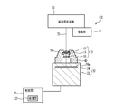
- FIG. 1 is a diagram showing an image inspection device 100 according to the first embodiment.
- the image inspection device 100 includes a mounting unit 1, an optical system 10, an imaging unit (imaging camera) 20, and a control unit 30.
- the image pickup unit 20 has an image pickup element 24 provided in the housing 22.
- the image sensor 24 is, for example, a CMOS (Complementary Metal Oxide Semiconductor) image sensor, but may be another case such as a CCD (Charge Coupled Device) image sensor.
- the optical system 10 includes a convex lens 12, a concave lens 14, and a convex lens 16.
- the convex lens 12, the concave lens 14, and the convex lens 16 are held by the holder 18.
- the holder 18 is fixed to the imaging unit 20 by the fixing member 40.
- the mounting unit 1 detachably mounts the image projection device 50, which is the inspection target of the image inspection device 100.
- the image projection device 50 is an image projection device that directly projects an image onto the retina of the user's eyeball, and is installed in the mounting unit 1 so that the emitted light rays 70 are incident on the optical system 10.
- the optical system 10 focuses the light beam 70 emitted from the image projection device 50 on the planar image pickup surface 24a or the vicinity of the image pickup surface 24a of the image pickup element 24.
- the control unit 30 is, for example, a processor such as a CPU (Central Processing Unit).
- the control unit 30 may be a circuit specially designed.
- the control unit 30 processes the image data captured by the image pickup unit 20 by a processor such as a CPU cooperating with the program to distort the image, resolution, brightness, pattern shape, gamma characteristic, contrast ratio, and aspect ratio. , And functions as an inspection unit 32 that inspects images such as hue. For these tests, commonly known methods can be used. Further, the control unit 30 may display the image data captured by the imaging unit 20 and / or the inspection data inspected by the inspection unit 32 on a display unit (for example, a liquid crystal display) (not shown).
- a display unit for example, a liquid crystal display
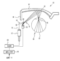
- the image projection device 50 is a retinal projection type head-mounted display that utilizes Maxwell vision in which light rays for allowing the user to visually recognize an image are directly applied to the user's retina. In Maxwell vision, the light rays forming the image converge the scanned light scanned in the two-dimensional direction near the pupil and project the image onto the retina.
- the image projection device 50 includes a light source 52, a mirror 54, a mirror 56, a scanning unit (scanner) 58, a mirror 60, a projection unit 62, a control unit 64, and an image input unit 66.
- the light source 52 and the scanning unit 58 are arranged, for example, on the vine 42 of the eyeglass-shaped frame.
- the projection unit 62 is arranged, for example, on the lens 44 of the glasses-type frame.
- the control unit 64 and the image input unit 66 may be provided on the vine 42 of the spectacle-type frame, or may be provided on an external device (for example, a mobile terminal) without being provided on the spectacle-type frame.
- Image data is input to the image input unit 66 from a camera, a recording device, and / or an image inspection device 100 (not shown).
- the control unit 64 controls the emission of the light rays 70 from the light source 52 and controls the scanning of the scanning unit 58 based on the input image data.
- the light source 52 emits light rays 70 having a single wavelength or a plurality of wavelengths under the control of the control unit 64.
- the light source 52 emits visible light such as red laser light (wavelength: about 610 nm to 660 nm), green laser light (wavelength: about 515 nm to 540 nm), and blue laser light (wavelength: about 440 nm to 480 nm).
- Examples of the light source 52 that emits red, green, and blue laser light include a light source in which RGB (red, green, and blue) laser diode chips and a three-color synthesis device are integrated.
- the control unit 64 is, for example, a processor such as a CPU (Central Processing Unit). If the camera is installed at an appropriate position of the image projection device 50 toward the user's line-of-sight direction, the image in the line-of-sight direction captured by the camera can be projected onto the retina 82 of the user's eyeball 80. In addition, a so-called Augmented Reality (AR) image is projected by projecting an image input from a recording device or the like, or superimposing a camera image and an image from a recording device or the like on the control unit 64. You can also let it.
- AR Augmented Reality
- the scanning unit 58 scans the light rays 70 emitted from the light source 52 at different times in the two-dimensional directions in the horizontal and vertical directions.
- the scanning unit 58 is, for example, a MEMS (Micro Electro Mechanical System) mirror, but may be another component such as a lithium niobate (KTN) crystal, which is an electrochemical material.
- KTN lithium niobate
- the scanning light 72 composed of the light rays 70 scanned by the scanning unit 58 is reflected by the mirror 60 toward the lens 44 of the glasses-type frame.
- the projection unit 62 is arranged on the surface of the lens 44 of the glasses-type frame on the eyeball 80 side. Therefore, the scanning light 72 is incident on the projection unit 62.
- the projection unit 62 is a free curved surface or a half mirror having a composite structure of a free curved surface and a diffractive surface.
- the scanning light 72 reflected by the projection unit 62 converges in the vicinity of the pupil 86 of the eyeball 80 and then irradiates the surface of the retina 82.
- the user can recognize the image by the afterimage effect of the scanning light 72 applied to the retina 82, and can visually recognize the external image through see-through.
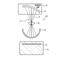
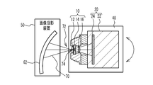
- FIG. 3 is a diagram illustrating a light beam 70 emitted from the image projection device 50 to the image sensor 24.
- the finite luminous flux diameter of the light beam 70 is illustrated, and the central portion thereof is illustrated by a broken line.
- the plurality of light rays 70 included in the scanning light 72 and emitted at different times are the image pickup surface 24a of the image pickup device 24 via the optical system 10 including the convex lens 12, the concave lens 14, and the convex lens 16. Is irradiated to.
- the plurality of light rays 70 are focused by the optical system 10 in the vicinity of the image pickup surface 24a or the image pickup surface 24a having a planar shape of the image pickup element 24.
- the light beam 70 is converted from substantially parallel light to focused light by the convex lens 12, converted from focused light to diffused light by the concave lens 14, and converted again from diffused light to focused light by the convex lens 16, and is converted to the imaging surface 24a or the imaging surface 24a or the imaging. Focus on the vicinity of the surface 24a.
- the convex lens 12 is, for example, a plano-convex lens in which the surface on the side where the light beam 70 (scanning light 72) is incident is a convex surface and the surface on the side where the light beam 70 (scanning light 72) is emitted is a flat surface.
- the concave lens 14 is, for example, a biconcave lens in which both the side where the light beam 70 is incident and the side where the light beam is emitted are concave.
- the convex lens 16 is, for example, a plano-convex lens in which the surface on the side where the light beam 70 is incident is a flat surface and the surface on the side where the light beam is emitted is a convex surface.
- the convex lens 12 and the concave lens 14 are arranged in contact with each other, for example.
- the concave lens 14 and the convex lens 16 are arranged apart, for example.
- the convex lens 12 and the concave lens 14 may be arranged at a distance narrower than the distance between the concave lens 14 and the convex lens 16.
- the scanning light 72 converges at the center of the convex surface on which the light rays 70 of the convex lens 12 are incident.
- the diameter of the light beam 70 when incident on the convex surface of the convex lens 12 is, for example, about 0.5 mm to 1 mm.
- the length dimension L from the convex surface of the convex lens 12 to the image pickup surface 24a of the image pickup element 24 is a distance obtained by correcting the length dimension from the surface of the crystalline lens of the human eyeball to the surface of the retina 82 in consideration of the refractive index of the eyeball. It corresponds to, for example, about 16 mm to 17 mm.
- the convex lenses 12 and 16 may be biconvex lenses in which both the incident side and the light emitting side of the light beam 70 are convex surfaces.
- the concave lens 14 may be a plano-concave lens in which one surface on the side where the light beam 70 is incident and the side where the light beam is emitted is a concave surface and the other surface is a flat surface.
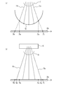
- FIG. 4 is a diagram showing an image inspection device 500 according to a comparative example.
- the image inspection device 500 of the comparative example includes a condenser lens 90, a projected unit 92, and an imaging unit (imaging camera) 94.
- the condenser lens 90 is provided on the optical path through which the light beam 70 reflected by the projection unit 62 of the image projection device 50 passes, and at a position where the scanning light 72 converges.
- the projected portion 92 is arranged near the focusing position of the light beam 70 by the condenser lens 90.
- the projected portion 92 has a hemispherical shape with the condenser lens 90 side open, and is made of a material that is translucent with respect to the light beam 70. Since the projected unit 92 is translucent with respect to the light rays 70, the projected image is displayed and the image is transmitted through the image projected by the scanning light 72.
- the condensing lens 90 that collects the light beam 70 can be regarded as the crystalline lens of the eyeball.
- the hemispherical projected portion 92 can be regarded as the retina of the eyeball. That is, a pseudo eye (dummy eye) is formed by the condenser lens 90 corresponding to the crystalline lens and the projected portion 92 corresponding to the retina. Therefore, the diameter of the projected portion 92 is the general size of the eyeball (for example, about 24 mm).
- the image pickup unit 94 has an image pickup element 96.
- the image sensor 96 is, for example, a CMOS image sensor.
- the imaging unit 94 is provided on the side opposite to the condenser lens 90 with respect to the projected unit 92.
- the imaging unit 94 captures an image projected on the projected unit 92.
- FIG. 5 (a) and 5 (b) are diagrams for explaining the problems that occur in the image inspection apparatus 500 according to the comparative example.
- FIG. 5B it is represented by the position coordinates with the center of the image projected by the image projection device 50 as the origin.
- the unit of the numerical value indicating the coordinates is mm.
- the plane expansion coordinates (circles), which are the positions of the light rays 70 when the projected portion 92 is deployed on a plane, are as shown in FIG. 5 (b).
- the light beam 70 applied to the projected portion 92 spreads outward as compared with the vertically projected coordinates (triangular marks) at which the light beam 70 is projected perpendicularly to the imaging surface 96a of the imaging element 96.
- the vertically projected coordinates (triangular marks) at which the light beam 70 is projected perpendicularly to the imaging surface 96a of the imaging element 96.
- the image inspection device 500 of the comparative example it is difficult to satisfactorily inspect the image projected on the user's retina by the image projection device 50.
- FIG. 6A and 6 (b) are diagrams for explaining the effect of the image inspection device 100 according to the first embodiment.
- the time differs depending on the image projection device 50.
- the light beam that is emitted and irradiates the retina 82 is referred to as a light ray 71.
- one of the rays near the edge of the image 76 is the ray 71a, and the ray symmetric with respect to the center of the image 76 is the ray 71b.
- the position where the light ray 71a irradiated on the retina 82 is projected perpendicularly to the imaging surface 24a is defined as the vertical projection position 73a
- the position where the light ray 71b irradiated on the retina 82 is projected perpendicularly to the imaging surface 24a is defined as the vertical projection position 75a. ..
- the position of the ray 71a on the imaging surface 24a when the retina 82 is expanded in a plane and the surface of the retina 82 is aligned with the imaging surface 24a is defined as the plane expansion position 73b
- the position of the ray 71b is defined as the plane expansion position 75b.
- Is the irradiation position 78a, and the position of the light ray 70b corresponding to the light ray 71b on the image pickup surface 24a is the irradiation position 78b.
- the irradiation position 78a is closer to the plane development position 73b than the vertical projection position 73a.
- the irradiation position 78b is made closer to the plane development position 75b than the vertical projection position 75a.
- the optical system 10 sets the irradiation position 78a at which the light ray 70a corresponding to the light ray 71a among the plurality of light rays 70 is applied to the imaging surface 24a from the retina 82 to the imaging surface 24a. It has an optical characteristic that is closer to the plane expansion position 73b when the retina 82 is plane-expanded than the vertically projected vertical projection position 73a. As a result, the image projected by the image projection device 50 can be inspected satisfactorily.
- the optical system 10 brings the irradiation position 78a closer to the plane development position 73b than the vertical projection position 73a, and the irradiation position where the light ray 70b corresponding to the light ray 71b among the plurality of light rays 70 is applied to the imaging surface 24a. It has an optical characteristic that the 78b is closer to the plane expansion position 75b when the retina 82 is plane-expanded than the vertical projection position 75a in which the light rays 71b are projected vertically from the retina 82 to the imaging surface 24a. As a result, the image projected by the image projection device 50 can be inspected satisfactorily.
- FIG. 6B shows an example in which the irradiation position 78a is located between the vertical projection position 73a and the plane expansion position 73b, and the irradiation position 78b is located between the vertical projection position 75a and the plane expansion position 75b. Is shown as an example, but it is not limited to this case.
- the irradiation position 78a may be located on the opposite side of the plane deployment position 73b from the vertical projection position 73a, or the irradiation position 78b may be located on the opposite side of the plane deployment position 75b from the vertical projection position 75a. May be good.
- the center distance between the irradiation position 78a and the plane development position 73b is preferably 1/2 or less, more preferably 1/3 or less of the center distance between the vertical projection position 73a and the plane development position 73b. It is more preferably 1/4 or less.
- the center distance between the irradiation position 78b and the plane development position 75b is preferably 1/2 or less, more preferably 1/3 or less, and further 1/4 or less of the center distance between the vertical projection position 75a and the plane development position 75b. preferable.
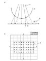
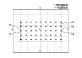
- FIG. 7 is a diagram showing calculation results of the position of the light ray 70 irradiated on the image pickup surface 24a of the image pickup element 24 and the position of the light ray 71 on the image pickup surface 24a when the retina 82 is developed in a plane.
- it is represented by the position coordinates with the center of the image projected by the image projection device 50 as the origin.
- the unit of the numerical value indicating the coordinates is mm.
- FIG. 7 is a calculation result when the convex lens 12, the concave lens 14, and the convex lens 16 having the specifications shown in Table 1 are used (note that the lenses having the same specifications are also used in FIGS. 8 to 12 shown below. It is the calculation result that was there).
- the convex lens 12 has a radius of curvature of 7.73 mm on the entrance surface, an infinite radius of curvature on the exit surface, a center thickness of 1.6 mm, a glass material of S-LAL8 manufactured by O'Hara, and a refractive index. 1.713 and the Abbe number was 53.87.
- the concave lens 14 has a radius of curvature of -12.08 mm on the entrance surface, a radius of curvature of 11.21 mm on the exit surface, a thickness of 1.0 mm at the center, a glass material of S-TIH10 manufactured by O'Hara, and a refractive index of 1.728.
- the Abbe number was set to 28.46.
- the convex lens 16 has an infinite radius of curvature on the incident surface, a radius of curvature on the exit surface of -8.43 mm, a center thickness of 1.4 mm, a glass material of S-LAM61 manufactured by O'Hara, a refractive index of 1.720, and an Abbe number. The number was 46.02. Further, the distance between the convex lens 12 and the center of the concave lens 14 is 0.39 mm, the distance between the concave lens 14 and the center of the convex lens 16 is 2.76 mm, and the distance between the center of the convex lens 16 and the imaging surface 24a is 14.79 mm. ..
- the light beam 70 covers the entire image 76 projected by the image projection device 50.
- the irradiation position coordinates (diamond mark), which is the position where the image is irradiated on the imaging surface 24a, and the plane expansion coordinates (circle mark), which is the position of the light ray 71 on the imaging surface 24a when the retina 82 is expanded in a plane, are approximately one. I am doing it.
- substantially coincidence means that 50% or more of the spot area of the light ray 70 on the image pickup surface 24a overlaps with the spot area of the light ray 71 on the image pickup surface 24a when the retina 82 is developed in a plane. is there.
- the light ray 71a on the image pickup surface 24a when the irradiation position 78a in which the light ray 70a irradiates the image pickup surface 24a expands the retina 82 in a plane so that the surface of the retina 82 coincides with the image pickup surface 24a. It is preferable to have an optical characteristic that substantially matches the plane development position 73b of. Further, in the optical system 10, the plane of the light ray 71b on the image pickup surface 24a when the irradiation position 78b in which the light ray 70b is applied to the image pickup surface 24a unfolds the retina 82 in a plane so that the surface of the retina 82 coincides with the image pickup surface 24a. It is preferable to have optical characteristics that substantially match the deployment position 75b. This makes it possible to better inspect the image projected by the image projection device 50.
- the optical system 10 has an imaging surface when the retina 82 is developed in a plane and the surface of the retina 82 is aligned with the imaging surface 24a at all of the plurality of irradiation positions where the plurality of light rays 70 are irradiated on the imaging surface 24a. It is preferable to have an optical characteristic that substantially matches the corresponding plane expansion position among the plurality of plane expansion positions of the plurality of light rays 71 in 24a. As a result, the image projected by the image projection device 50 can be inspected even better.
- the plurality of irradiation positions where the plurality of light rays 70 are irradiated on the imaging surface 24a correspond to the plurality of plane expansion positions of the plurality of rays 71 on the imaging surface 24a when the retina 82 is plane-expanded. It may be a case where the plane development position is substantially the same. More than 90% of the plurality of irradiation positions where the plurality of light rays 70 are applied to the imaging surface 24a correspond to the corresponding planes among the plurality of plane development positions of the plurality of rays 71 on the image pickup surface 24a when the retina 82 is expanded in a plane. It may be a case where the expansion position is substantially the same.
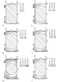
- FIG. 8A is a diagram showing the calculation result of the streak ratio when the light ray 71 composed of the green laser light is irradiated from the image projection device 50 to the user's retina 82.
- FIG. 8B is a diagram showing a calculation result of the streak ratio when a light beam 70 composed of green laser light is irradiated from the image projection device 50 to the image pickup surface 24a of the image pickup device 24 via the optical system 10.
- the streak ratio is the maximum intensity ratio of the intensity distribution of the irradiated laser.
- the wavelength is ⁇
- the RMS (root mean square) value of the wave surface aberration is W
- S It is calculated by 1- (2 ⁇ / ⁇ ) 2 ⁇ W 2 .
- FIG. 8 (c) is a dotted line ratio of FIGS. 8 (a) and 8 (b).
- the scanning angle of the scanning unit with the center of the image projected by the image projection device 50 as the origin is represented.
- the coordinate axis is the angle (°) of the scanning angle.
- the optical characteristics such as the curvature of each lens constituting the optical system 10 and the distance between the lenses are appropriately designed, and the green laser light (wavelength: 520 nm).
- the trail ratio when the image pickup surface 24a of the image pickup element 24 is irradiated is substantially the same as the trail ratio when the green laser light is irradiated to the retina 82. That is, the tendency that the stray ratio in the central portion of the image is high and the strail ratio in the peripheral portion is low is reproduced on the image pickup surface 24a of the image pickup device 24 by appropriately designing the optical system 10.
- 9 (a) to 9 (c) are diagrams showing the calculation result of the streak ratio when the light ray 71 composed of red, green, or blue laser light is irradiated from the image projection device 50 to the user's retina 82. is there.
- 9 (d) to 9 (f) show the case where the light beam 70 composed of red, green, or blue laser light is irradiated from the image projection device 50 to the image pickup surface 24a of the image pickup device 24 via the optical system 10. It is a figure which shows the calculation result of a stray ratio.
- 9 (a) to 9 (f) show the scanning angle of the scanning unit with the center of the image projected by the image projection device 50 as the origin. The coordinate axis is the angle (°) of the scanning angle.
- the green laser light is emitted from the image pickup element 24 by appropriately designing the optical characteristics such as the curvature of each lens constituting the optical system 10 and the distance between the lenses.
- the trail ratio when the imaging surface 24a is irradiated is substantially the same as the trail ratio when the green laser light is irradiated to the retina 82.
- the blue laser light (wavelength: 450 nm) is irradiated to the imaging surface 24a as shown in FIGS. 9 (a) and 9 (d).
- the trail ratio at that time shows the same tendency as the trail ratio when the blue laser light is applied to the retina 82. That is, the tendency that the stray ratio in the central portion of the image is high and the strail ratio in the peripheral portion is low is reproduced on the imaging surface 24a.
- the streak ratio when the red laser light (wavelength: 640 nm) is applied to the imaging surface 24a is such that the red laser light is applied to the retina 82. It shows the same tendency as the strare ratio at the time. That is, the tendency that the stray ratio in the central portion of the image is high and the strail ratio in the peripheral portion is low is reproduced on the imaging surface 24a.
- the optical system 10 has an optical characteristic that makes the stray ratio at the center of the image captured by the image sensor 24 higher than the stray ratio at the ends. preferable. As a result, the image projected by the image projection device 50 can be inspected satisfactorily.
- the difference between the trail ratio when the green laser light is applied to the imaging surface 24a and the trail ratio when the green laser light is applied to the retina 82 is detected on the imaging surface 24a by the blue laser light. It is preferable to have an optical characteristic that makes the difference between the strail ratio when irradiated and the stray ratio when the blue laser light is irradiated to the retina 82 smaller than the difference. Further, in the optical system 10, the difference between the trail ratio when the green laser light is applied to the imaging surface 24a and the trail ratio when the green laser light is applied to the retina 82 is detected on the imaging surface 24a by the red laser light.
- the wavelength band of the green laser light is located between the wavelength band of the blue laser light and the wavelength band of the red laser light. Therefore, by reducing the difference between the trail ratio on the imaging surface 24a with the green laser light and the trail ratio on the retina 82, the difference between the trail ratio on the imaging surface 24a with the blue and red laser light and the trail ratio on the retina 82. Can be made smaller. Therefore, the image projected by the image projection device 50 can be inspected satisfactorily.
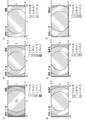
- 10 (a) to 10 (c) are diagrams showing the calculation results of RMS wave surface aberration when a ray 71 composed of red, green, or blue laser light is applied from the image projection device 50 to the user's retina 82.
- Is. 10 (d) to 10 (f) show a case where a light ray 70 composed of red, green, or blue laser light is irradiated from the image projection device 50 to the image pickup surface 24a of the image pickup device 24 via the optical system 10. It is a figure which shows the calculation result of RMS wave surface aberration.
- 10 (a) to 10 (f) show the scanning angle of the scanning unit with the center of the image projected by the image projection device 50 as the origin. The coordinate axis is the angle (°) of the scanning angle.
- the green laser light (wavelength: 520 nm) is obtained by appropriately designing the optical characteristics such as the curvature of each lens constituting the optical system 10 and the distance between the lenses. ) Approximately matches the RMS wave surface aberration when the image pickup surface 24a of the image pickup element 24 is irradiated with the RMS wave surface aberration when the green laser light is applied to the retina 82. That is, the tendency that the RMS value in the central portion of the image is small and the RMS value in the peripheral portion is large is reproduced on the image pickup surface 24a of the image pickup device 24.
- the blue laser light (wavelength: 450 nm) is transmitted to the imaging surface 24a as shown in FIGS. 10 (a) and 10 (d).
- the RMS value when irradiated shows the same tendency as the RMS value when the blue laser light irradiates the retina 82. That is, the tendency that the RMS value in the central portion of the image is small and the RMS value in the peripheral portion is large is reproduced on the imaging surface 24a.
- FIGS. 10 (a) and 10 (d) shows the same tendency as the RMS value when the blue laser light irradiates the retina 82. That is, the tendency that the RMS value in the central portion of the image is small and the RMS value in the peripheral portion is large is reproduced on the imaging surface 24a.
- the RMS value when the red laser light (wavelength: 640 nm) is applied to the imaging surface 24a is such that the red laser light is applied to the retina 82. It shows the same tendency as the RMS value at. That is, the tendency that the RMS value in the central portion of the image is small and the RMS value in the peripheral portion is large is reproduced on the imaging surface 24a.
- the optical system 10 has an optical characteristic that makes the RMS wave surface aberration at the central portion of the image captured by the image sensor 24 smaller than the RMS wave surface aberration at the end portion. You may.
- FIG. 11A is a diagram showing the calculation result of the color shift of the light beam 71 when the user's retina 82 is developed in a plane
- FIG. 11B is a diagram on the image pickup surface 24a of the image pickup device 24 via the optical system 10. It is a figure which shows the calculation result of the color shift of the light ray 70 to be irradiated.
- the scanning angle of the scanning unit with the center of the image projected by the image projection device 50 as the origin is represented.
- the coordinate axis is the angle (°) of the scanning angle.
- the image projection device 50 to the retina 82 The red laser light R, the green laser light G, and the blue laser light of the corresponding light rays are formed by the plurality of light rays 71 irradiated on the light beam 71 and the plurality of light rays 70 irradiated on the image pickup surface 24a of the image pickup element 24 from the image projection device 50.
- the tendency of the misalignment of B is matched.
- the red laser beam R is displaced outward with respect to the green laser beam G
- the blue laser beam B is displaced with respect to the green laser beam G.
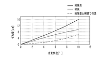
- FIG. 12 is a diagram showing the amount of misalignment between the green laser beam and the blue laser beam on the X-axis of FIGS. 11 (a) and 11 (b).
- the amount of misalignment between the green laser beam G and the blue laser beam B irradiated on the imaging surface 24a of the imaging device 24 is shown by a thick line
- the misalignment between the green laser beam G and the blue laser beam B irradiated on the retina 82 is shown by a thick line.
- the amount is indicated by a thin line.
- the difference in the amount of misalignment is shown by a broken line.
- the amount of misalignment between the green laser beam G and the blue laser beam B is the difference between the center position of the green laser beam G and the center position of the blue laser beam B.
- the difference between the amount of misalignment of the green laser light and the blue laser light on the imaging surface 24a of the imaging element 24 and the amount of misalignment of the green laser light and the blue laser light on the retina 82 as the distance from the origin increases. Is getting bigger.
- the difference between the amount of misalignment between the green laser light and the blue laser light on the image pickup surface 24a of the image sensor 24 and the amount of misalignment between the green laser light and the blue laser light on the retina 82 is 6 ⁇ m. It has become a degree.
- Table 2 shows the amount of misalignment of the green laser light and the blue laser light irradiated on the imaging surface 24a of the imaging element 24 and the retina 82 at points A to E in FIGS. 11 (a) and 11 (b). The difference between the emitted green laser light and the amount of misalignment of the blue laser light is shown. Further, Table 2 shows the amount of misalignment of the red laser light and the green laser light and the retina irradiated on the imaging surface 24a of the imaging element 24 at points A to E in FIGS. 11 (a) and 11 (b). The difference between the amount of misalignment between the red laser light and the green laser light irradiated to 82 is shown.
- the difference between the amount of misalignment between the green laser light and the blue laser light on the imaging surface 24a of the image pickup element 24 and the amount of misalignment between the green laser light and the blue laser light on the retina 82 is 12.32 ⁇ m or less. It is about 13 ⁇ m or less.
- the difference between the amount of misalignment between the red laser light and the green laser light on the imaging surface 24a of the image pickup element 24 and the amount of misalignment between the red laser light and the green laser light on the retina 82 is 12.32 ⁇ m or less, which is approximately the same. It is 13 ⁇ m or less.
- the spot diameter on the retina 82 is about 40 ⁇ m. Therefore, even if there is a difference of about 13 ⁇ m in the amount of misalignment around the projected image, the influence on inspecting the quality of the image projected by the image projection device 50 is small.
- the optical system 10 has a red laser beam and a blue laser beam with respect to the green laser beam when a plurality of light rays 70 are applied to the imaging surface 24a of the imaging device 24. It is preferable to have an optical characteristic that the misalignment direction is the same as the misalignment direction of the red laser light and the blue laser light with respect to the green laser light when the plurality of light rays 71 irradiate the user's retina 82. As a result, the image projected by the image projection device 50 can be inspected satisfactorily.
- the case where the optical system 10 includes the convex lens 12, the concave lens 14, and the convex lens 16 which are arranged in order from the side where the scanning light 72 is incident is shown as an example, but other cases may be used.
- the optical system 10 is composed of three lenses, a convex lens 12, a concave lens 14, and a convex lens 16, the configuration of the optical system 10 can be simplified.
- the case where the scanning light 72 is focused on the convex surface of the convex lens 12 is shown as an example, but other cases may be used.
- the optical system 10 may be provided at the convergence position of the scanning light 72.
- the resolution of the image sensor 24 is preferably equal to or higher than the resolution of the image projected by the image projection device 50.
- 13 (a) to 13 (d) are diagrams for explaining the reason why it is preferable that the resolution of the image pickup device 24 is equal to or higher than the resolution of the image projected by the image projection device 50.
- 13 (a) is a diagram showing an image projected on the image pickup surface 24 a of the image sensor 24 by the image projection device 50
- FIGS. 13 (b) to 13 (d) are images captured by the image sensor 24. It is a figure which shows.
- the saturation (shading) of the black-and-white image projected by the image projection device 50 is represented by the hatching density.
- the image of the black pattern 46 is projected in the image projection area 68 by the image projection device 50.
- the area between the black patterns 46 is a region where the light rays 70 are not irradiated from the image projection device 50 and the patterns are not projected.
- the resolution of the image sensor 24 is lower than the resolution of the image projected by the image projection device 50 as shown in FIG. 13B, a part of the black pattern 46 is not periodically imaged and the color of the black pattern 46 is colored.
- a black pattern 46a that does not accurately reflect the degree (shade) may be imaged. As shown in FIG.
- the resolution of the image pickup device 24 is preferably twice or more the resolution of the image projected by the image projection device 50 from the viewpoint of more accurately reflecting the shading of the image projected by the image projection device 50 for imaging. It is more preferably 3 times or more, and further preferably 4 times or more.
- FIG. 14 is a diagram illustrating an image projection area 68 of the image projection device 50 and an image pickup area 26 of the image sensor 24.
- the image pickup region 26 of the image pickup device 24 is preferably larger than the image projection area 68 of the image projection device 50.
- the length of the vertical side of the image projection region 26 is preferably 1.2 times or more, more preferably 1.5 times or more, still more preferably 1.8 times or more the length of the vertical side of the image projection area 68.
- the length of the horizontal side of the image projection region 26 is preferably 1.2 times or more, more preferably 1.5 times or more, still more preferably 1.8 times or more the length of the horizontal side of the image projection area 68.
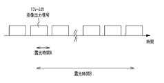
- the image sensor 24 captures an image projected by the image projection device 50 with one or a plurality of continuous exposure times, and the one continuous exposure time is the inverse of the frame rate of the image projected by the image projection device 50. Is preferably longer. For example, one continuous exposure time of the image sensor 24 is longer than 1/60 second when the frame rate of the image projected by the image projection device 50 is 60 fps, and when the frame rate of the image is 30 fps. It is preferably longer than 1/30 second.
- FIG. 15 is a diagram for explaining the reason why it is preferable that one exposure time of the image pickup device 24 is longer than the reciprocal of the frame rate of the image projected by the image projection device 50.
- one exposure time A of the image pickup device 24 is shorter than the reciprocal of the frame rate of the image projected by the image projection device 50, the entire image may not be captured.
- one exposure time B of the image sensor 24 is made longer than the inverse number of the frame rate of the image projected by the image projection device 50, the image pickup is started from the middle of the projected image and the image pickup is performed in the middle. It is possible to suppress that the entire image is not captured after finishing.
- one exposure time of the image sensor 24 is twice or more the inverse of the frame rate of the image projected by the image projection device 50. , It is more preferable that it is as long as possible.
- the image projection timing by the image projection device 50 and the image pickup timing by the image sensor 24 may be imaged by the image sensor 24 by synchronizing with (horizontal synchronization, vertical synchronization, etc.). In this case, since the image projection timing and the image pickup timing are synchronized, the image sensor 24 can capture an image of one frame or a plurality of frames.
- FIG. 16 is a diagram illustrating rotation of the optical system 10 and the image pickup unit 20 with respect to the image projection device 50.
- the optical system 10 and the optical system 10 and the convergence point 74 of the scanning light 72 projected from the projection unit 62 of the image projection device 50 the portion of the convex surface on which the light ray 70 of the convex lens 12 is incident in the first embodiment.
- the image pickup unit 20 may be rotatable with respect to the image projection device 50.
- the rotation of the optical system 10 and the imaging unit 20 with respect to the image projection device 50 may be a rotation in the left-right direction, a rotation in the up-down direction, or a rotation in the up-down-left-right direction.
- the optical system 10 and the imaging unit 20 move the image projection device 50 around the position where the scanning light 72 emitted from the image projection device 50 converges. It is preferable that the image is rotatable.
- the relative rotation of the optical system 10 and the image pickup unit 20 with respect to the image projection device 50 may be performed by placing the optical system 10 and the image pickup unit 20 on the stage 48 and rotating the stage 48, or the like. It may be done by the method of.
- the rotation of the optical system 10 and the imaging unit 20 may be performed by the inspector manually moving the stage 48, or by the inspector giving an instruction to the control unit 30 and the control unit 30 moving the stage 48. You may go.
Abstract
La présente invention concerne un dispositif d'inspection d'images qui comprend une partie de montage sur laquelle est monté un dispositif de projection d'images destiné à projeter directement une image sur une rétine, un élément imageur qui a une surface imageuse planaire et qui capture une image projetée depuis le dispositif de projection d'images sur la surface imageuse, un système optique qui est disposé en une position où converge une pluralité de premiers faisceaux de lumière émis par le dispositif de projection d'images à différents instants et qui concentre la pluralité de premiers faisceaux de lumière émis par le dispositif de projection d'images sur la surface imageuse ou dans son voisinage, et une unité d'inspection destinée à inspecter l'image capturée par l'élément imageur. En supposant qu'il y a une rétine dans la direction de la partie de montage depuis la surface imageuse et étant donné une première position où, parmi une pluralité de deuxièmes faisceaux de lumière émis par le dispositif de projection d'images à différents instants et frappant la rétine, un troisième faisceau de lumière proche du bord de l'image est projeté verticalement sur la surface imageuse, et une deuxième position qui serait la position de la surface imageuse du troisième faisceau de lumière si la rétine était étendue dans une surface plate et que l'on faisant coïncider la surface de la rétine avec la surface imageuse, le système optique fait en sorte qu'une troisième position, laquelle est la position de la surface imageuse frappée par un quatrième faisceau de lumière parmi la pluralité de premiers faisceaux de lumière qui correspond au troisième faisceau de lumière, s'approche de la deuxième position plus que de la première position.
Priority Applications (1)
| Application Number | Priority Date | Filing Date | Title |
|---|---|---|---|
| CN202080012119.4A CN113383220A (zh) | 2019-04-04 | 2020-02-20 | 图像检查装置 |
Applications Claiming Priority (2)
| Application Number | Priority Date | Filing Date | Title |
|---|---|---|---|
| JP2019072259A JP7123403B2 (ja) | 2019-04-04 | 2019-04-04 | 画像検査装置 |
| JP2019-072259 | 2019-04-04 |
Publications (1)
| Publication Number | Publication Date |
|---|---|
| WO2020202877A1 true WO2020202877A1 (fr) | 2020-10-08 |
Family
ID=72667812
Family Applications (1)
| Application Number | Title | Priority Date | Filing Date |
|---|---|---|---|
| PCT/JP2020/006747 WO2020202877A1 (fr) | 2019-04-04 | 2020-02-20 | Dispositif d'inspection d'images |
Country Status (4)
| Country | Link |
|---|---|
| JP (1) | JP7123403B2 (fr) |
| CN (1) | CN113383220A (fr) |
| TW (1) | TWI794590B (fr) |
| WO (1) | WO2020202877A1 (fr) |
Families Citing this family (1)
| Publication number | Priority date | Publication date | Assignee | Title |
|---|---|---|---|---|
| JP7089823B1 (ja) | 2022-03-28 | 2022-06-23 | 株式会社Qdレーザ | 画像投影装置、視覚検査装置、および眼底撮影装置 |
Citations (5)
| Publication number | Priority date | Publication date | Assignee | Title |
|---|---|---|---|---|
| JPH10108835A (ja) * | 1996-08-16 | 1998-04-28 | Hoya Corp | 眼光学系のシミュレーション装置 |
| JPH11249085A (ja) * | 1998-03-06 | 1999-09-17 | Hoya Corp | 疑似視覚装置 |
| JPH11249086A (ja) * | 1998-03-06 | 1999-09-17 | Hoya Corp | 疑似視覚レンズ並びにこれを用いた疑似視覚カメラ及び疑似視覚装置 |
| CN106343950A (zh) * | 2016-09-28 | 2017-01-25 | 天津工业大学 | 一种基于眼模型的眼底相机双目立体成像系统 |
| WO2018034181A1 (fr) * | 2016-08-18 | 2018-02-22 | 株式会社Qdレーザ | Dispositif d'inspection d'image, procédé d'inspection d'image et composant de dispositif d'inspection d'image |
Family Cites Families (12)
| Publication number | Priority date | Publication date | Assignee | Title |
|---|---|---|---|---|
| AU3193900A (en) * | 1999-03-18 | 2000-10-04 | Nikon Corporation | Exposure system and aberration measurement method for its projection optical system, and production method for device |
| JP2002184667A (ja) * | 2000-12-14 | 2002-06-28 | Nikon Corp | 補正部材の製造方法、投影光学系の製造方法および露光装置の調整方法 |
| JP2004172316A (ja) * | 2002-11-19 | 2004-06-17 | Nikon Corp | 投影光学系の収差計測方法及び装置、並びに露光装置 |
| EP1883354A2 (fr) | 2005-04-29 | 2008-02-06 | Novadaq Technologies Inc. | Systeme d'imagerie et de traitement de la choroide et de la retine |
| JP5462288B2 (ja) | 2009-03-04 | 2014-04-02 | パーフェクト アイピー エルエルシー | レンズを形成および修正するためのシステムならびにそれによって形成されたレンズ |
| JP6209456B2 (ja) * | 2013-05-31 | 2017-10-04 | 株式会社Qdレーザ | 画像投影装置及び投射装置 |
| WO2016035055A1 (fr) | 2014-09-05 | 2016-03-10 | Hoya Corporation | Profondeur étendue de lentilles intraocculaires à vortex de foyer et procédés associés |
| JP6231541B2 (ja) * | 2015-06-25 | 2017-11-15 | 株式会社Qdレーザ | 画像投影装置 |
| WO2016208266A1 (fr) * | 2015-06-25 | 2016-12-29 | 株式会社Qdレーザ | Dispositif de projection d'image |
| IL242895B (en) * | 2015-12-03 | 2021-04-29 | Eyeway Vision Ltd | Image projection system |
| CN109073501B (zh) * | 2016-04-14 | 2021-03-23 | Agc株式会社 | 检查装置、检查方法 |
| JP6612812B2 (ja) * | 2017-06-06 | 2019-11-27 | 株式会社Qdレーザ | 画像投影装置 |
-
2019
- 2019-04-04 JP JP2019072259A patent/JP7123403B2/ja active Active
-
2020
- 2020-02-20 CN CN202080012119.4A patent/CN113383220A/zh active Pending
- 2020-02-20 WO PCT/JP2020/006747 patent/WO2020202877A1/fr active Application Filing
- 2020-02-26 TW TW109106330A patent/TWI794590B/zh active
Patent Citations (5)
| Publication number | Priority date | Publication date | Assignee | Title |
|---|---|---|---|---|
| JPH10108835A (ja) * | 1996-08-16 | 1998-04-28 | Hoya Corp | 眼光学系のシミュレーション装置 |
| JPH11249085A (ja) * | 1998-03-06 | 1999-09-17 | Hoya Corp | 疑似視覚装置 |
| JPH11249086A (ja) * | 1998-03-06 | 1999-09-17 | Hoya Corp | 疑似視覚レンズ並びにこれを用いた疑似視覚カメラ及び疑似視覚装置 |
| WO2018034181A1 (fr) * | 2016-08-18 | 2018-02-22 | 株式会社Qdレーザ | Dispositif d'inspection d'image, procédé d'inspection d'image et composant de dispositif d'inspection d'image |
| CN106343950A (zh) * | 2016-09-28 | 2017-01-25 | 天津工业大学 | 一种基于眼模型的眼底相机双目立体成像系统 |
Also Published As
| Publication number | Publication date |
|---|---|
| TW202037893A (zh) | 2020-10-16 |
| CN113383220A (zh) | 2021-09-10 |
| JP7123403B2 (ja) | 2022-08-23 |
| JP2020170118A (ja) | 2020-10-15 |
| TWI794590B (zh) | 2023-03-01 |
Similar Documents
| Publication | Publication Date | Title |
|---|---|---|
| CN110753876B (zh) | 图像投影装置 | |
| CN110709755B (zh) | 图像投影装置 | |
| CN110192143B (zh) | 图像投影装置 | |
| CN109642848B (zh) | 图像检查装置以及图像检查方法 | |
| JP2001512994A (ja) | 広い視野をレーザ走査する検眼鏡 | |
| US20080151190A1 (en) | Corneal measurment apparatus and a method of using the same | |
| CN211270678U (zh) | 眼底相机的光学系统及眼底相机 | |
| US20200333135A1 (en) | Patterned light projection apparatus and method | |
| JP2018514802A (ja) | 単一カメラを使用して遠隔物体を2つ以上のスペクトルチャネルで同時に画像化する為の多波長ビームスプリッタシステム | |
| WO2020202877A1 (fr) | Dispositif d'inspection d'images | |
| CN112869703B (zh) | 眼底相机的光学系统及眼底相机 | |
| WO2021132588A1 (fr) | Dispositif d'imagerie de fond d'œil optique à balayage | |
| JPWO2019045094A1 (ja) | 走査型眼底撮影装置 | |
| JP2021062162A (ja) | 走査型眼底撮影装置 | |
| JP7089823B1 (ja) | 画像投影装置、視覚検査装置、および眼底撮影装置 | |
| JP6937536B1 (ja) | 眼底撮影装置 | |
| CN212346501U (zh) | 眼底相机的杂散光消除系统 | |
| US11822077B2 (en) | Virtual or augmented reality vision system with image sensor of the eye | |
| JP7435961B2 (ja) | 眼底撮影装置 | |
| WO2021049405A1 (fr) | Dispositif d'imagerie de cellules endothéliales cornéennes, procédé de commande et programme associés | |
| JP2023546873A (ja) | 光学装置のためのインライン計測システム、装置、及び方法 | |
| JPH01285242A (ja) | 前眼部断面撮影装置 |
Legal Events
| Date | Code | Title | Description |
|---|---|---|---|
| 121 | Ep: the epo has been informed by wipo that ep was designated in this application |
Ref document number: 20782536 Country of ref document: EP Kind code of ref document: A1 |
|
| NENP | Non-entry into the national phase |
Ref country code: DE |
|
| 122 | Ep: pct application non-entry in european phase |
Ref document number: 20782536 Country of ref document: EP Kind code of ref document: A1 |