WO2020202612A1 - Dispositif de traitement d'image, procédé, et programme - Google Patents
Dispositif de traitement d'image, procédé, et programme Download PDFInfo
- Publication number
- WO2020202612A1 WO2020202612A1 PCT/JP2019/041480 JP2019041480W WO2020202612A1 WO 2020202612 A1 WO2020202612 A1 WO 2020202612A1 JP 2019041480 W JP2019041480 W JP 2019041480W WO 2020202612 A1 WO2020202612 A1 WO 2020202612A1
- Authority
- WO
- WIPO (PCT)
- Prior art keywords
- specific structure
- composite
- image
- pixels
- tomographic images
- Prior art date
Links
- 238000000034 method Methods 0.000 title claims description 66
- 238000012545 processing Methods 0.000 title claims description 55
- 238000000605 extraction Methods 0.000 claims abstract description 16
- 239000000284 extract Substances 0.000 claims abstract description 8
- 239000002131 composite material Substances 0.000 claims description 95
- 230000005855 radiation Effects 0.000 claims description 76
- 238000003384 imaging method Methods 0.000 claims description 29
- 210000000481 breast Anatomy 0.000 claims description 26
- 238000001514 detection method Methods 0.000 claims description 12
- 238000009499 grossing Methods 0.000 claims description 11
- 238000012937 correction Methods 0.000 claims description 8
- 238000003672 processing method Methods 0.000 claims description 3
- 230000002194 synthesizing effect Effects 0.000 abstract description 3
- 230000000875 corresponding effect Effects 0.000 description 74
- 238000010586 diagram Methods 0.000 description 14
- 238000003860 storage Methods 0.000 description 14
- 230000015572 biosynthetic process Effects 0.000 description 13
- 238000003786 synthesis reaction Methods 0.000 description 13
- 210000005075 mammary gland Anatomy 0.000 description 7
- 230000006835 compression Effects 0.000 description 5
- 238000007906 compression Methods 0.000 description 5
- 206010028980 Neoplasm Diseases 0.000 description 4
- 230000006870 function Effects 0.000 description 4
- 230000003287 optical effect Effects 0.000 description 4
- 230000002159 abnormal effect Effects 0.000 description 3
- 238000004195 computer-aided diagnosis Methods 0.000 description 3
- 230000001678 irradiating effect Effects 0.000 description 3
- 230000003902 lesion Effects 0.000 description 3
- 208000004434 Calcinosis Diseases 0.000 description 2
- 230000002308 calcification Effects 0.000 description 2
- 239000003925 fat Substances 0.000 description 2
- 238000001914 filtration Methods 0.000 description 2
- 239000000203 mixture Substances 0.000 description 2
- 206010006187 Breast cancer Diseases 0.000 description 1
- 208000026310 Breast neoplasm Diseases 0.000 description 1
- 102100035353 Cyclin-dependent kinase 2-associated protein 1 Human genes 0.000 description 1
- 101000710013 Homo sapiens Reversion-inducing cysteine-rich protein with Kazal motifs Proteins 0.000 description 1
- 102100029860 Suppressor of tumorigenicity 20 protein Human genes 0.000 description 1
- 238000013459 approach Methods 0.000 description 1
- 238000006243 chemical reaction Methods 0.000 description 1
- 230000002596 correlated effect Effects 0.000 description 1
- 238000003745 diagnosis Methods 0.000 description 1
- 238000002059 diagnostic imaging Methods 0.000 description 1
- 238000009826 distribution Methods 0.000 description 1
- 230000005611 electricity Effects 0.000 description 1
- 230000007717 exclusion Effects 0.000 description 1
- 238000002474 experimental method Methods 0.000 description 1
- 239000004973 liquid crystal related substance Substances 0.000 description 1
- 238000009607 mammography Methods 0.000 description 1
- 238000004519 manufacturing process Methods 0.000 description 1
- 239000000463 material Substances 0.000 description 1
- 238000005070 sampling Methods 0.000 description 1
- 229920006395 saturated elastomer Polymers 0.000 description 1
- 239000004065 semiconductor Substances 0.000 description 1
- 238000004088 simulation Methods 0.000 description 1
- 239000007787 solid Substances 0.000 description 1
- 239000010409 thin film Substances 0.000 description 1
Images


Classifications
-
- A—HUMAN NECESSITIES
- A61—MEDICAL OR VETERINARY SCIENCE; HYGIENE
- A61B—DIAGNOSIS; SURGERY; IDENTIFICATION
- A61B6/00—Apparatus or devices for radiation diagnosis; Apparatus or devices for radiation diagnosis combined with radiation therapy equipment
- A61B6/50—Apparatus or devices for radiation diagnosis; Apparatus or devices for radiation diagnosis combined with radiation therapy equipment specially adapted for specific body parts; specially adapted for specific clinical applications
- A61B6/502—Apparatus or devices for radiation diagnosis; Apparatus or devices for radiation diagnosis combined with radiation therapy equipment specially adapted for specific body parts; specially adapted for specific clinical applications for diagnosis of breast, i.e. mammography
-
- G—PHYSICS
- G06—COMPUTING; CALCULATING OR COUNTING
- G06T—IMAGE DATA PROCESSING OR GENERATION, IN GENERAL
- G06T7/00—Image analysis
- G06T7/0002—Inspection of images, e.g. flaw detection
- G06T7/0012—Biomedical image inspection
-
- A—HUMAN NECESSITIES
- A61—MEDICAL OR VETERINARY SCIENCE; HYGIENE
- A61B—DIAGNOSIS; SURGERY; IDENTIFICATION
- A61B6/00—Apparatus or devices for radiation diagnosis; Apparatus or devices for radiation diagnosis combined with radiation therapy equipment
- A61B6/02—Arrangements for diagnosis sequentially in different planes; Stereoscopic radiation diagnosis
- A61B6/025—Tomosynthesis
-
- G—PHYSICS
- G06—COMPUTING; CALCULATING OR COUNTING
- G06T—IMAGE DATA PROCESSING OR GENERATION, IN GENERAL
- G06T2207/00—Indexing scheme for image analysis or image enhancement
- G06T2207/10—Image acquisition modality
- G06T2207/10072—Tomographic images
-
- G—PHYSICS
- G06—COMPUTING; CALCULATING OR COUNTING
- G06T—IMAGE DATA PROCESSING OR GENERATION, IN GENERAL
- G06T2207/00—Indexing scheme for image analysis or image enhancement
- G06T2207/10—Image acquisition modality
- G06T2207/10072—Tomographic images
- G06T2207/10081—Computed x-ray tomography [CT]
-
- G—PHYSICS
- G06—COMPUTING; CALCULATING OR COUNTING
- G06T—IMAGE DATA PROCESSING OR GENERATION, IN GENERAL
- G06T2207/00—Indexing scheme for image analysis or image enhancement
- G06T2207/30—Subject of image; Context of image processing
- G06T2207/30004—Biomedical image processing
- G06T2207/30068—Mammography; Breast
-
- G—PHYSICS
- G06—COMPUTING; CALCULATING OR COUNTING
- G06T—IMAGE DATA PROCESSING OR GENERATION, IN GENERAL
- G06T2207/00—Indexing scheme for image analysis or image enhancement
- G06T2207/30—Subject of image; Context of image processing
- G06T2207/30004—Biomedical image processing
- G06T2207/30096—Tumor; Lesion
Definitions
- This disclosure relates to image processing devices, methods and programs.
- tomosynthesis photography As a method of photographing a radiation image, so-called tomosynthesis photography is known in which radiation is sequentially irradiated from each of a plurality of irradiation positions having different irradiation angles and a plurality of projected images are taken by a radiation detector for each irradiation position. Further, there is known a technique of generating a tomographic image by a reconstruction process from a plurality of projected images acquired by tomosynthesis imaging.
- CAD Computer Aided Diagnosis
- CAD Computer Aided Diagnosis
- diagnostically important structures such as spicula and tumors are extracted from breast images using CAD.
- a method of extracting a region of interest including a lesion by CAD and synthesizing the extracted region of interest on a composite 2D image has been proposed (see US Pat. No. 8,983,156).
- a method has also been proposed in which the characteristics of common regions in a plurality of images including tomographic images are compared, the image having the best characteristics is identified, and the common regions of specially made images are combined to generate a composite two-dimensional image.
- a method has been proposed in which an edge is detected from a tomographic image, the detected edge is expanded to generate a weighted region, and a composite two-dimensional image is generated in consideration of the weight of the weighted region (US Pat. No. 1). See specification 10140715).
- a linear structure such as spicula is a structure that is important for diagnosis (hereinafter referred to as a specific structure), so it is necessary to include it in the composite two-dimensional image so as to be clear.
- a specific structure a structure that is important for diagnosis
- the extracted regions of interest or structures are linear when composited onto a composite two-dimensional image.
- the signal values of the structure are averaged. Therefore, the linear structure may be buried in other regions on the composite two-dimensional image, making it difficult to see. Further, in the method described in US Pat. No.
- edges such as normal mammary glands included in upper and lower tomographic images of a linear structure such as spicula are detected. Therefore, in a synthetic two-dimensional image, The edges of the mammary glands and the spicula overlap, making it difficult to see the spicula. Further, in the method described in US Pat. No. 10,140,715, the detected edges of the mammary glands and the like may overlap, and a structure that looks like a spicula may appear in the synthetic two-dimensional image.
- the present disclosure has been made in view of the above circumstances, and an object of the present disclosure is to make it easier to see a specific structure included in a tomographic image in a composite two-dimensional image.
- the image processing apparatus includes a structure extraction unit that extracts a specific structure from each of a plurality of tomographic images representing a plurality of tomographic surfaces of a subject. It is provided with a compositing unit that generates a composite two-dimensional image from a plurality of tomographic images by making the weight of pixels of a specific structure in each of the plurality of tomographic images larger than the weights of pixels other than the specific structure.
- the compositing unit sets the weight of the corresponding pixel corresponding to the specific structure included in the other tomographic image in the pixels other than the specific structure in each of the plurality of tomographic images. It may be smaller than the weight of the pixel of.
- the compositing unit may set the weight of the corresponding pixel to 0.
- the compositing unit may set the weight of the specific structure in each of the plurality of tomographic images to 1.
- the compositing unit may normalize the pixel value of the specific structure on the composite two-dimensional image based on the maximum value of the pixel value that the composite two-dimensional image can take.
- the compositing unit may generate a composite two-dimensional image by weighting and adding the pixel values of the corresponding pixels of a plurality of tomographic images by weights. ..
- tomosynthesis imaging is performed in which the radiation source is moved relative to the detection surface of the detection unit and the subject is irradiated with radiation at a plurality of radiation source positions due to the movement of the radiation source.
- An image acquisition unit that acquires a plurality of projected images corresponding to each of a plurality of source positions, which is generated by the operation of It further includes a reconstruction unit that generates a plurality of tomographic images by reconstructing a plurality of projected images.
- the image processing apparatus is further provided with a misalignment correction unit for correcting misalignment between a plurality of projected images.
- the reconstructing unit may generate a plurality of tomographic images by reconstructing a plurality of projected images corrected for misalignment.
- the compositing unit may perform smoothing processing on the boundary of a specific structure in the composite two-dimensional image.
- the “smoothing process” means a process of smoothly changing the pixel value near the boundary of a specific structure to match the pixel value of the background in contact with the boundary.
- the compositing unit in each of the plurality of tomographic images, has a specific structure for pixels other than the corresponding pixels corresponding to the pixels of the specific structure and the specific structure included in the other tomographic images.
- the weighting of the noise pixels, which are more affected by noise than the above, may be lowered, or the noise pixels may be excluded to generate a composite two-dimensional image.
- the subject may be a breast and the specific structure may be a spicula or a mass.
- the image processing method extracts a specific structure from each of a plurality of tomographic images representing a plurality of tomographic surfaces of a subject.
- the weight of the pixel of the specific structure in each of the plurality of tomographic images is made larger than the weight of the pixel of the non-specific structure to generate a composite two-dimensional image from the plurality of tomographic images.
- image processing devices include a memory for storing an instruction to be executed by a computer and a memory.
- the processor comprises a processor configured to execute a stored instruction.
- a specific structure is extracted from each of multiple tomographic images representing multiple tomographic surfaces of the subject.
- the weight of the pixel of the specific structure in each of the plurality of tomographic images is made larger than the weight of the pixel of the non-specific structure, and the process of generating the composite two-dimensional image from the plurality of tomographic images is executed.
- the view of the radiation imaging apparatus from the direction of arrow A in FIG. The figure which shows the schematic structure of the image processing apparatus realized by installing the image processing program in the computer in this embodiment.
- Diagram to illustrate the acquisition of projected images Diagram to explain the generation of tomographic images
- Diagram to explain the extraction of specific structures from tomographic images Diagram for explaining the generation of a composite 2D image
- Diagram to illustrate weight setting Diagram to illustrate weight setting
- the figure for demonstrating the generation of the composite 2D image by the set weight Flowchart showing processing performed in this embodiment Flowchart showing processing performed in this embodiment Flowchart showing processing performed in this embodiment
- the figure which shows the probability near a specific structure at the time of a specific structure detection The figure which shows the weight of a specific structure at the time of performing a smoothing process
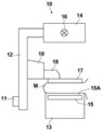
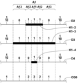
- FIG. 1 is a schematic configuration diagram of a radiation imaging device to which the image processing device according to the embodiment of the present disclosure is applied
- FIG. 2 is a view of the radiation imaging device viewed from the direction of arrow A in FIG.
- the radiographic image capturing apparatus 1 captures a breast M, which is a subject, from a plurality of radiation source positions in order to perform tomosynthesis imaging of the breast and generate a tomographic image, and acquires a plurality of radiographic images, that is, a plurality of projected images. It is a mammography imaging device.
- the radiographic image capturing apparatus 1 includes a photographing unit 10, a computer 2 connected to the photographing unit 10, a display unit 3 connected to the computer 2, and an input unit 4.
- the photographing unit 10 includes an arm unit 12 connected to a base (not shown) by a rotating shaft 11.
- An imaging table 13 is attached to one end of the arm portion 12, and an irradiation unit 14 is attached to the other end so as to face the photographing table 13.
- the arm portion 12 is configured so that only the end portion to which the radiation irradiation unit 14 is attached can be rotated, whereby the imaging table 13 can be fixed and only the radiation irradiation unit 14 can be rotated. It has become.
- the rotation of the arm portion 12 is controlled by the computer 2.
- a radiation detector 15 such as a flat panel detector is provided inside the photographing table 13.
- the radiation detector 15 has a radiation detection surface 15A. Further, inside the photographing table 13, a charge amplifier that converts the charge signal read from the radiation detector 15 into a voltage signal, a correlated double sampling circuit that samples the voltage signal output from the charge amplifier, and a voltage signal. A circuit board or the like provided with an AD (Analog Digital) conversion unit or the like for converting the voltage into a digital signal is also installed.
- the radiation detector 15 corresponds to the detection unit. Further, in the present embodiment, the radiation detector 15 is used as the detection unit, but the radiation detector 15 is not limited as long as it can detect the radiation and convert it into an image.
- the radiation detector 15 can repeatedly record and read a radiation image, and may use a so-called direct type radiation detector that directly converts radiation such as X-rays into a charge, or radiation. You may use a so-called indirect radiation detector that once converts the visible light into visible light and then converts the visible light into a charge signal. Further, as a radiation image signal reading method, a so-called TFT reading method in which a radiation image signal is read by turning on and off a TFT (Thin Film Transistor) switch, or a radiation image signal by irradiating the read light. It is desirable to use a so-called optical reading method in which
- the radiation source 16 is housed inside the radiation irradiation unit 14.
- the radiation source 16 emits X-rays as radiation, and the timing of irradiating the radiation from the radiation source 16 and the radiation generation conditions in the radiation source 16, that is, the selection of the material of the target and the filter, the tube voltage, the irradiation time, and the like are determined. It is controlled by the computer 2.
- a compression plate 17 which is arranged above the imaging table 13 and presses and presses the breast M, a support portion 18 which supports the compression plate 17, and a support portion 18 are vertically attached to FIGS. 1 and 2.
- a moving mechanism 19 for moving in a direction is provided. The distance between the compression plate 17 and the photographing table 13, that is, the compression thickness is input to the computer 2.
- the display unit 3 is a display device such as a CRT (Cathode Ray Tube) or a liquid crystal monitor, and displays a projected image, a tomographic image, a composite two-dimensional image, etc. acquired as described later, as well as a message necessary for operation. ..
- the display unit 3 may have a built-in speaker that outputs sound.
- the input unit 4 includes an input device such as a keyboard, a mouse, or a touch panel method, and receives an operation of the radiographic image capturing device 1 by an operator. It also accepts instructions for inputting various information such as shooting conditions and correcting information necessary for performing tomosynthesis shooting. In the present embodiment, each part of the radiographic imaging apparatus 1 operates according to the information input from the input unit 4 by the operator.
- the image processing program according to this embodiment is installed on the computer 2.
- the computer 2 may be a workstation or a personal computer directly operated by the operator, or may be a server computer connected to them via a network.
- the image processing program is recorded and distributed on a recording medium such as a DVD (Digital Versatile Disc) or a CD-ROM (Compact Disc Read Only Memory), and is installed in a computer from the recording medium.
- a recording medium such as a DVD (Digital Versatile Disc) or a CD-ROM (Compact Disc Read Only Memory)
- it is stored in the storage device of the server computer connected to the network or in the network storage in a state where it can be accessed from the outside, and is downloaded and installed in the computer upon request.
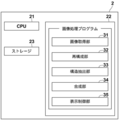
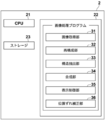
- FIG. 3 is a diagram showing a schematic configuration of an image processing apparatus realized by installing an image processing program according to the present embodiment on the computer 2.
- the image processing apparatus includes a CPU (Central Processing Unit) 21, a memory 22, and a storage 23 as a standard computer configuration.
- CPU Central Processing Unit
- the storage 23 is composed of a storage device such as a hard disk drive or an SSD (Solid State Drive), and stores various information including a program for driving each part of the radiation imaging apparatus 1 and an image processing program.
- a storage device such as a hard disk drive or an SSD (Solid State Drive)
- various information including a program for driving each part of the radiation imaging apparatus 1 and an image processing program.
- the projected image acquired by tomosynthesis imaging, the tomographic image generated as described later, and the composite two-dimensional image are also stored.
- the memory 22 temporarily stores a program or the like stored in the storage 23 in order to cause the CPU 21 to execute various processes.
- the image processing program causes the radiation image capturing apparatus 1 to perform tomosynthesis imaging, and acquires a plurality of projected images of the breast M corresponding to each of the plurality of source positions.
- Reconstruction processing that generates tomographic images at each of the multiple tomographic planes of the breast M that is the subject by reconstructing the projected image of, structure extraction processing that extracts a specific structure from each of the plurality of tomographic images, and a plurality of The weight of the pixel of the specific structure in each of the tomographic images is made larger than the weight of the pixel other than the specific structure, and the composite process of generating a composite two-dimensional image from a plurality of tomographic images, and the composite two-dimensional image display unit
- the display control process to be displayed in 3 is specified.
- the computer 2 functions as an image acquisition unit 31, a reconstruction unit 32, a structure extraction unit 33, a composition unit 34, and a display control unit 35.
- the image acquisition unit 31 moves the radiation source 16 by rotating the arm unit 12 around the rotation axis 11 when performing the image acquisition process, and is used for tomosynthesis imaging at a plurality of radiation source positions due to the movement of the radiation source 16.
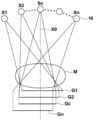
- FIG. 4 is a diagram for explaining the acquisition of the projected image Gi.
- the radiation source 16 is moved to each source position of S1, S2, ..., Sn, and the radiation source 16 is driven at each source position to irradiate the breast M with radiation, and the breast M is irradiated.
- projected images G1, G2, ..., Gn are acquired corresponding to the source positions S1 to Sn.
- the same dose of radiation is applied to the breast M.
- the acquired plurality of projected images Gi are stored in the storage 23.
- a plurality of projected images Gi may be acquired by a program separate from the image processing program and stored in the storage 23 or an external storage device. In this case, the image acquisition unit 31 reads out a plurality of projected image Gis stored in the storage 23 or the external storage device from the storage 23 or the external storage device for reconstruction processing or the like.
- the radiation source position Sc is the radiation source position where the optical axis X0 of the radiation emitted from the radiation source 16 is orthogonal to the detection surface 15A of the radiation detector 15.
- the radiation source position Sc shall be referred to as a reference radiation source position Sc.
- the structure extraction unit 33 extracts a specific structure from a plurality of tomographic images Dj.
- the spicula and the mass contained in the breast M are extracted as specific structures.
- FIG. 6 is a diagram for explaining the extraction of a specific structure.
- the detection of a specific structure from the tomographic image Dk of one of the plurality of tomographic images Dj will be described.
- the tomographic image Dk includes the spicula and the mass on the tomographic surface of the breast M from which the tomographic image Dk was acquired as specific structures K1 to K3.
- the specific structure includes spicula, which is a linear structure around the tumor.
- the structure extraction unit 33 extracts a specific structure from the tomographic image Dk by using a known computer-aided diagnosis (CAD: Computer Aided Diagnosis, hereinafter referred to as CAD) algorithm.
- CAD Computer Aided Diagnosis
- a probability indicating that a pixel in the tomographic image Dj has a specific structure is derived, and when the probability is equal to or higher than a predetermined threshold value, the pixel is detected as a specific structure. Extraction of a specific structure is not limited to those using CAD.
- the specific structure may be extracted from the tomographic image Dk by filtering processing with a filter for extracting the specific structure or the like.
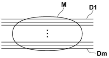
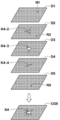
- the composite unit 34 is a composite two-dimensional image CG0 which is a pseudo two-dimensional image corresponding to a simple two-dimensional image taken by irradiating the breast M with radiation from the reference radiation source position Sc using a plurality of tomographic images Dj. To generate.
- the synthesis unit 34 shows the viewpoint direction from the reference radiation source position Sc toward the radiation detector 15, that is, FIG. 4 in a state where a plurality of tomographic images Dj are stacked.
- a composite two-dimensional image CG0 is generated by an addition method in which the pixel values of the corresponding pixels in each tomographic image Dj are weighted and added along the optical axis X0.
- the generation of the composite two-dimensional image CG0 is not limited to the addition method, and a known technique can be applied.
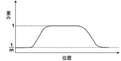
- the weight for each pixel at the time of weighting addition is basically set to 1 / m when the number of tomographic images Dj is m, and a composite two-dimensional image CG0 is generated.
- the weights of the pixels of the specific structure in each of the plurality of tomographic images Dj are made larger than the weights of the pixels other than the specific structure, and the composite two-dimensional image CG0 is generated.
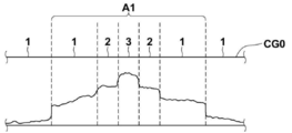
- FIG. 8 is a diagram for explaining the setting of weights in the present embodiment.
- 10 tomographic images D1 to D10 are generated for explanation, the specific structure K1 is included in the tomographic images D2 to D4, and the specific structure K2 is included in the tomographic images D3 to D6.
- the specific structure K3 is included in the tomographic image D8.
- the specific structures K1 to K3 have a thickness in FIG. 8 for the sake of explanation, they are not actually thick.
- the specific structure K1 included in each of the tomographic images D2 to D4 is designated as the specific structure K1-2, K1-3, K1-4, respectively.
- the specific structure K2 included in each of the tomographic images D3 to D6 is designated as the specific structure K2-3, K2-4, K2-5, K2-6.
- the specific structure K1 shown in FIG. 8 is included over three tomographic images D2 to D4.
- the size of the specific structure K1-3 included in the tomographic image D3 is the largest.
- the synthesizing unit 34 makes the weight of the corresponding pixel corresponding to the specific structure K1 smaller than the weight of the pixels other than the corresponding pixel.
- the weight of the corresponding pixel which is a pixel in the corresponding region A1 on the tomographic images D1, D5 to D10 corresponding to the specific structure K1 shown in FIG. 8, is larger than the weight of the pixel in the region other than the corresponding region A1. Make it smaller.
- the weight of the corresponding pixel in the corresponding region A1 on the tomographic images D1, D5 to D10 is set to 0.
- the region of the specific structure K1-2 is smaller than the corresponding region A1. Therefore, the compositing unit 34 sets the weight of the pixels in the region other than the specific structure K1-2 in the corresponding region A1 of the tomographic image D2 to 0.
- the region of the specific structure K1-4 is smaller than the corresponding region A1. Therefore, the synthesis unit 34 also sets the weight of the pixels in the region other than the specific structure K1-4 in the corresponding region A1 of the tomographic image D4 to 0. The process of setting the weight will be described later.
- the specific structure K2 shown in FIG. 8 is included over four tomographic images D3 to D6. Further, the size of the specific structure K2-5 included in the tomographic image D5 is the largest.
- the synthesis unit 34 makes the weight of the corresponding pixel corresponding to the specific structure K2 smaller than the weight of the pixels other than the corresponding pixel. Specifically, the weight of the corresponding pixel, which is the pixel in the corresponding region A2 on the tomographic images D1, D2, D7 to D10 corresponding to the specific structure K2 shown in FIG. 8, is set to 0.
- the region of the specific structure K2-3 is smaller than the corresponding region A2. Therefore, the compositing unit 34 sets the weight of the pixels in the region other than the specific structure K2-3 in the corresponding region A2 of the tomographic image D3 to 0. Further, in the tomographic image D4, the region of the specific structure K2-4 is smaller than the corresponding region A2. Therefore, the compositing unit 34 sets the weight of the pixels in the region other than the specific structure K2-4 in the corresponding region A2 of the tomographic image D4 to 0. Further, in the tomographic image D6, the region of the specific structure K2-6 is smaller than the corresponding region A2. Therefore, the compositing unit 34 sets the weight of the pixels in the region other than the specific structure K2-6 in the corresponding region A2 of the tomographic image D6 to 0.
- the specific structure K3 shown in FIG. 8 is included in only one tomographic image D8.
- the synthesis unit 34 makes the weight of the corresponding pixel corresponding to the specific structure K3 smaller than the weight of the non-corresponding pixel in the tomographic images D1 to 7, D9, and D10 that do not include the specific structure K3. That is, the weight of the corresponding pixel in the corresponding region A3 on the tomographic images D1 to 7, D9, and D10 corresponding to the specific structure K3 shown in FIG. 8 is set to 0.
- the compositing unit 34 sets the weight to 1 for the pixels of the specific structures K1 to K3 in each of the plurality of tomographic images Dj.
- the total value of the weights of the pixels of the specific structure in the composite two-dimensional image CG0 becomes the number of pixels of the specific structure included in the corresponding pixels. That is, the pixel value of the specific structure in the composite two-dimensional image CG0 is the sum of the pixel values of the specific structure in each of the tomographic images Dj.
- FIG. 9 is a diagram for explaining the setting of weights for a specific structure.
- the weight may be set for the specific structures K2 and K3 in the same manner.
- the compositing unit 34 sets the weight to 1 for the pixels in the region of the specific structure K1 in the tomographic images D2 to D4.
- the weight of the pixel in the corresponding region A1 is 0. Therefore, on the composite two-dimensional image CG0, three specific structures K1-2 and K1-3 among the pixels in the corresponding region A1 corresponding to the specific structure K1.
- the total value of the weights is 3.
- the pixels in the region A12 in which only the two specific structures K1-2 and K1-3 in the tomographic images D2 and D3 overlap are the sum of the weights.
- the value is 2.
- the total weight value is 1.
- the number of tomographic images is 10 for the pixels in the region that does not overlap with any specific structure included in the other tomographic images D1 and D5 to D10. Therefore, if the noise pixels described later are not taken into consideration, the compositing unit 34 sets the weight of the pixels in this region to 1/10. Therefore, on the composite two-dimensional image CG0, the total value of the weights is 1 for the pixels in the region that does not overlap with any specific structure.
- the weight of the pixel of the specific structure included in each tomographic image Dj becomes larger than the weight of the pixel other than the specific structure.
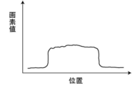
- the pixel value of the specific structure is larger than the pixel value of the structure other than the specific structure. Therefore, in the composite two-dimensional image CG0 generated by the weights set as described above, the pixel values of the pixels in the corresponding region A10 have a value larger than that of the other regions, as shown in FIG. Become.
- the synthesis unit 34 has a noise component ratio in a region having a specific structure and a region other than the corresponding region corresponding to the specific structure (hereinafter referred to as another region).
- noise pixels For pixels that are highly affected by noise (hereinafter referred to as noise pixels), the weighting of the noise pixels is lowered or the noise pixels are excluded when the composite two-dimensional image CG0 is generated.
- the exclusion of noise pixels is equivalent to setting the weight of noise pixels to 0. In this embodiment, the weight for the noise pixel is set to 0.
- the synthesis unit 34 derives the average value of the pixel values of all the pixels to be added when the composite two-dimensional image CG0 is generated for the other regions of the plurality of tomographic images Dj, and each pixel. Pixels whose absolute value obtained by dividing the average value from the value is equal to or less than a predetermined threshold Th are regarded as noise pixels, and the weight for the noise pixels is set to 0.
- the threshold value Th may be determined in advance by an experiment, a simulation, or the like according to the magnitude of the superimposed noise.
- FIG. 11 is a diagram for explaining the generation of a composite two-dimensional image.
- the tomographic images D2 to D4 of the tomographic images D1 to D5 include specific structures K4-2, K4-3, and K4-4 representing the same specific structure, respectively.
- the specific structures K4-2, K4-3, and K4-4 spicula, which is a linear structure, exists around the tumor.
- the tomographic images D1, D2, and D5 contain noises N1, N2, and N5, respectively.
- the weight of the pixels of the specific structure K4-2, K4-3, K4-4 is larger than the weight of the pixels in the region other than the specific structure K4-2, K4-3, K4-4. ..
- the weights are set to 1, respectively.
- the weights of the pixels in the corresponding region corresponding to the specific structures K4-2, K4-3, and K4-4 in the tomographic images D1 and D5 are set to 0. Therefore, the signal value of the pixel of the specific structure K4 in the composite two-dimensional image CG0 is an addition value of only the signal values of the specific structures K4-2, K4-3, and K4-4 included in the tomographic images D2 to D4. Therefore, in the composite two-dimensional image CG0, the specific structure is not buried in other regions.
- the weight is 1/5. Further, for noise pixels, the weight is set to 0 at the time of synthesis. Therefore, the regions other than the specific structure K4 in the composite two-dimensional image CG0 have substantially the same signal values as the pixels in the regions other than the specific structure in the tomographic images D1 to D5, and noise is generated. It will be removed.
- the weight at the time of addition is set based on the value obtained by subtracting the number of noise pixels from the number of tomographic images. That is, when the composite two-dimensional image CG0 is generated by adding m tomographic images, if there are d noise pixels in the tomographic image Dj corresponding to a certain pixel on the composite two-dimensional image CG0, the pixel is The weight of is 1 / (md) instead of 1 / m.
- the pixel value of the specific structure on the composite two-dimensional image CG0 is the maximum value of the pixel values that the composite two-dimensional image CG0 can take. May exceed.
- the total value of the weights is 3 for the pixels in the region A11 in which all of the specific structures K1-2, K1-3, and K1-4 overlap.
- the maximum value of the pixel values that the composite two-dimensional image CG0 can take is 1024, and the specific structures K1-2 and K1-3.
- each pixel value of K1-4 is 512
- the pixel value in the composite two-dimensional image CG0 is 1536
- the maximum value of the pixel value that the composite two-dimensional image CG0 can take is larger than 1024.
- the pixel is in a state where the pixel value is saturated. Therefore, when the pixel value of the specific structure on the composite two-dimensional image CG0 is larger than the maximum value of the pixel value that the composite two-dimensional image CG0 can take, the compositing unit 34 determines the specific structure on the composite two-dimensional image CG0.
- the pixel values of the pixels in the region are normalized by the maximum value of the pixel values that the composite two-dimensional image CG0 can take.
- the pixel value in the composite two-dimensional image CG0 is 1536 and the value becomes the maximum value of the pixel value in the specific structure
- the pixel value in the specific structure is normalized so that the pixel value 1536 becomes 1024.
- the pixel values of all the pixels in the specific structure are normalized so as to be 1024/1536 times. This makes it possible to prevent saturation of the pixel values in the specific structure included in the composite two-dimensional image CG0.
- FIG. 12 is a flowchart showing the processing performed in the present embodiment.
- the input unit 4 receives an instruction from the operator to start processing, tomosynthesis imaging is performed, and the image acquisition unit 31 acquires a plurality of projected images Gi (step ST1).
- the reconstruction unit 32 generates a plurality of tomographic images Dj on the plurality of tomographic planes of the breast M by reconstructing the plurality of projected images Gi (step ST2).
- the number of tomographic images is m.
- the structure extraction unit 33 extracts a specific structure from each of the plurality of tomographic images Dj (step ST3).
- the compositing unit 34 sets the weights for generating the composite two-dimensional image CG0 for each pixel of the plurality of tomographic images Dj (weight setting process; step ST4).
- step ST13 the compositing unit 34 determines whether or not the corresponding pixel corresponding to the pixel of interest has a pixel having a specific structure in the tomographic image other than the kth tomographic image. Step ST15). When step ST15 is affirmed, the compositing unit 34 sets the weight of the pixel of interest to 0 (step ST16) and proceeds to step ST21. If step ST15 is denied, the compositing unit 34 determines whether or not the pixel of interest is a noise pixel (step ST17). When step ST17 is affirmed, the compositing unit 34 sets the weight of the pixel of interest to 0 (step ST18), and proceeds to step ST21.
- step ST17 When step ST17 is denied, the compositing unit 34 counts the number d of tomographic images in which the corresponding pixel corresponding to the pixel of interest is a noise pixel in the tomographic image other than the kth tomographic image (step ST19). ), Set the weight of the pixel of interest to 1 / (md) (step ST20), and proceed to step ST21.
- step ST21 the compositing unit 34 determines whether or not the weights of all the pixels are set for the kth tomographic image.
- step ST21 the pixel of interest is changed to the next pixel (step ST22), the process returns to step ST13, and the processes after step ST13 are repeated.
- step ST23 the weight setting process ends.
- the compositing unit 34 generates a composite two-dimensional image CG0 from a plurality of tomographic images Dk using the set weights (step ST5). At this time, if necessary, as described above, the pixel values of the pixels of the specific structure on the composite two-dimensional image CG0 are normalized by the maximum value of the pixel values of the composite two-dimensional image CG0. Then, the display control unit 35 displays the composite two-dimensional image CG0 on the display unit 3 (step ST6), and ends the process.
- the specific structure is extracted from each of the plurality of tomographic images Dj representing the tomographic plane of the breast M, and the weights of the pixels of the specific structure in each of the plurality of tomographic images Dj are set to other than the specific structure.
- the composite two-dimensional image CG0 is generated from a plurality of tomographic images Dj by making it larger than the weight of the pixels of. Therefore, in the composite two-dimensional image CG0, the specific structure is not buried in the region other than the specific structure. Therefore, according to the present embodiment, the specific structure can be easily seen in the composite two-dimensional image CG0.
- the structures such as spicula and tumor are high-intensity (white), and the other fats are low-intensity (black).
- the signal value of the corresponding pixel position in the tomographic image when the composite two-dimensional image CG0 is generated. Is equalized, so that the fat region contained in the composite two-dimensional image CG0 becomes whitish as compared with the simple two-dimensional image. Therefore, the texture of the composite two-dimensional image CG0 is different from the texture of the simple two-dimensional image. Further, in the method described in US Pat. No.
- edges such as normal mammary glands included in upper and lower tomographic images of a linear structure such as spicula are detected, and therefore, in the synthetic two-dimensional image CG0, ,
- the edges of the mammary glands and the spicula overlap, making it difficult to see the spicula.
- the detected edges of the mammary glands and the like may overlap, and a structure that looks like a spicula may appear in the synthetic two-dimensional image CG0.
- the weight of the corresponding pixel corresponding to the specific structure included in the other tomographic image is made smaller than the weight of the pixel other than the corresponding pixel, preferably 0. ..
- the composite two-dimensional image CG0 can have the same texture as the simple two-dimensional image.
- the composite two-dimensional image CG0 it is possible to prevent the specific structure from overlapping with the structure other than the specific structure, making the specific structure difficult to see. Further, it is possible to prevent a structure different from the specific structure, which looks like the specific structure, from appearing in the composite two-dimensional image CG0.
- a plurality of tomographic images are acquired by tomosynthesis imaging.
- Tomosynthesis imaging also has a problem that the reconstructed tomographic image is blurred due to the influence of the mechanical error of the imaging device and the body movement of the subject due to the time difference of imaging at each of the multiple source positions. .. If the tomographic image is blurred in this way, it becomes difficult to detect lesions such as minute calcifications, which are useful for early detection of breast cancer.
- a misalignment correction unit for correcting misalignment due to body movement or the like between a plurality of projected images acquired by tomosynthesis imaging. 36 may be provided.
- any method such as the method described in Japanese Patent Application Laid-Open No. 2016-064119 can be used.
- the method described in Japanese Patent Application Laid-Open No. 2016-064119 is a method for correcting a positional deviation between a plurality of projected images Gi so that the positions of the plurality of projected images Gis match.
- SIFT Scale-Invariant Feature Transform
- SURF Speeded Up Robust Features
- the minute calcification contained in the breast M does not disappear in the tomographic image. Therefore, in the composite two-dimensional image CG0, the abnormal portion can be completely expressed.
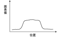
- the compositing unit may perform a smoothing process on the boundary of the specific structure when generating the composite two-dimensional image CG0.
- the smoothing process means a process of smoothly changing the pixel value near the boundary of a specific structure to match the pixel value of the background in contact with the boundary.
- the smoothing process is performed by changing the weight near the boundary of the specific structure. The weight at this time may be set based on the probability when the structure extraction unit 33 detects the specific structure.
- the distribution of the probabilities output by the structure extraction unit 33 is shown in FIG.
- the probability output by the structure extraction unit 33 becomes smaller toward the periphery of the specific structure, and the region of the probability of becoming the threshold value Th1 or more is detected as the specific structure. Therefore, as shown in FIG. 17, the compositing unit 34 sets the weight for the specific structure so as to gradually decrease from 1 to 1 / m as the pixels around the specific structure correspond to the probability of the specific structure.
- the specific structure having an unnaturally clear pixel value at the boundary with the surroundings has a pixel value at which the boundary with the surroundings changes smoothly as shown in FIG. Become.
- the boundary of the specific structure gradually approaches the pixel value of the background in which the pixel value of the specific structure is adjacent. Therefore, it is possible to generate a composite two-dimensional image CG0 in which a specific structure and its background intersect more naturally.
- the smoothing process is not limited to the method using the weight derived as described above.
- the smoothing process may be performed by filtering the boundary of the specific structure included in the composite two-dimensional image CG0 with a low-pass filter.
- the pixels in the corresponding region corresponding to the specific structure and the specific structure of the other tomographic image are noise pixels. It is not limited to.
- a value 1 / m obtained by dividing 1 by the number m of tomographic images may be set as a weight without determining whether or not the pixel is a noise pixel.
- the weight of the specific structure is set to 1 in each of the tomographic images Dj, but the weight is not limited to this.
- the weight of the pixels of the specific structure may be set to 1 / c.
- the compositing unit 34 sets the weights of the pixels having the specific structure so that the total weights are 1 when the composite two-dimensional image CG0 is generated.
- the addition method is applied as a method in which the synthesis unit 34 generates a composite two-dimensional image, but as described above, other known techniques can be applied. For example, a so-called shortest path method may be applied, which uses the minimum value in the corresponding pixel of each tomographic image.
- the radiation in the above embodiment is not particularly limited, and ⁇ rays, ⁇ rays, etc. can be applied in addition to X-rays.
- a processing unit that executes various processes such as an image acquisition unit 31, a reconstruction unit 32, a structure extraction unit 33, a composition unit 34, a display control unit 35, and a misalignment correction unit 36.
- various processors Processors
- the various processors include a CPU, which is a general-purpose processor that executes software (program) and functions as various processing units, and a circuit after manufacturing an FPGA (Field Programmable Gate Array) or the like.
- Dedicated electricity which is a processor with a circuit configuration specially designed to execute specific processing such as programmable logic device (PLD), ASIC (Application Specific Integrated Circuit), which is a processor whose configuration can be changed. Circuits and the like are included.
- One processing unit may be composed of one of these various processors, or a combination of two or more processors of the same type or different types (for example, a combination of a plurality of FPGAs or a combination of a CPU and an FPGA). ) May be configured. Further, a plurality of processing units may be configured by one processor.
- one processor is configured by combining one or more CPUs and software. There is a form in which this processor functions as a plurality of processing units.
- SoC System On Chip
- the various processing units are configured by using one or more of the various processors as a hardware structure.
- circuitry in which circuit elements such as semiconductor elements are combined can be used.
Landscapes
- Engineering & Computer Science (AREA)
- Health & Medical Sciences (AREA)
- Life Sciences & Earth Sciences (AREA)
- Medical Informatics (AREA)
- Physics & Mathematics (AREA)
- General Health & Medical Sciences (AREA)
- Nuclear Medicine, Radiotherapy & Molecular Imaging (AREA)
- Radiology & Medical Imaging (AREA)
- Molecular Biology (AREA)
- Heart & Thoracic Surgery (AREA)
- Veterinary Medicine (AREA)
- Public Health (AREA)
- Biophysics (AREA)
- High Energy & Nuclear Physics (AREA)
- Optics & Photonics (AREA)
- Pathology (AREA)
- Biomedical Technology (AREA)
- Animal Behavior & Ethology (AREA)
- Surgery (AREA)
- Quality & Reliability (AREA)
- General Physics & Mathematics (AREA)
- Computer Vision & Pattern Recognition (AREA)
- Theoretical Computer Science (AREA)
- Dentistry (AREA)
- Oral & Maxillofacial Surgery (AREA)
- Apparatus For Radiation Diagnosis (AREA)
Abstract
Dans la présente invention, une unité d'extraction de structure extrait une structure prescrite à partir de chacune d'une pluralité d'images de section transversale montrant une pluralité de surfaces de section transversale d'un sujet. Une unité de synthèse règle la pondération des pixels de la structure prescrite dans chacune de la pluralité d'images de section transversale pour être plus grande que la pondération de pixels autres que ceux de la structure prescrite, puis génère une image 2D synthétisée à partir de la pluralité d'images de section transversale.
Priority Applications (3)
| Application Number | Priority Date | Filing Date | Title |
|---|---|---|---|
| JP2021511086A JP7187678B2 (ja) | 2019-03-29 | 2019-10-23 | 画像処理装置、方法およびプログラム |
| EP19922862.8A EP3949862A4 (fr) | 2019-03-29 | 2019-10-23 | Dispositif de traitement d'image, procédé, et programme |
| US17/464,723 US20210393226A1 (en) | 2019-03-29 | 2021-09-02 | Image processing apparatus, image processing method, and image processing program |
Applications Claiming Priority (2)
| Application Number | Priority Date | Filing Date | Title |
|---|---|---|---|
| JP2019067746 | 2019-03-29 | ||
| JP2019-067746 | 2019-03-29 |
Related Child Applications (1)
| Application Number | Title | Priority Date | Filing Date |
|---|---|---|---|
| US17/464,723 Continuation US20210393226A1 (en) | 2019-03-29 | 2021-09-02 | Image processing apparatus, image processing method, and image processing program |
Publications (1)
| Publication Number | Publication Date |
|---|---|
| WO2020202612A1 true WO2020202612A1 (fr) | 2020-10-08 |
Family
ID=72667877
Family Applications (1)
| Application Number | Title | Priority Date | Filing Date |
|---|---|---|---|
| PCT/JP2019/041480 WO2020202612A1 (fr) | 2019-03-29 | 2019-10-23 | Dispositif de traitement d'image, procédé, et programme |
Country Status (4)
| Country | Link |
|---|---|
| US (1) | US20210393226A1 (fr) |
| EP (1) | EP3949862A4 (fr) |
| JP (1) | JP7187678B2 (fr) |
| WO (1) | WO2020202612A1 (fr) |
Cited By (2)
| Publication number | Priority date | Publication date | Assignee | Title |
|---|---|---|---|---|
| EP4066745A1 (fr) * | 2021-03-29 | 2022-10-05 | FUJI-FILM Corporation | Dispositif, procédé et programme de traitement d'image |
| EP4066744A1 (fr) * | 2021-03-29 | 2022-10-05 | FUJI-FILM Corporation | Dispositif, procédé et programme de traitement d'image |
Citations (8)
| Publication number | Priority date | Publication date | Assignee | Title |
|---|---|---|---|---|
| JPS5952251B2 (ja) | 1978-02-21 | 1984-12-19 | 川崎重工業株式会社 | 大型構造物沈下構築方法 |
| US20140327702A1 (en) | 2005-11-10 | 2014-11-06 | Hologic, Inc | System and method for generating a 2d image using mammography and/or tomosynthesis image data |
| US8983156B2 (en) | 2012-11-23 | 2015-03-17 | Icad, Inc. | System and method for improving workflow efficiences in reading tomosynthesis medical image data |
| JP2015205019A (ja) * | 2014-04-21 | 2015-11-19 | ジーイー・メディカル・システムズ・グローバル・テクノロジー・カンパニー・エルエルシー | 画像処理装置、放射線断層撮影装置及びプログラム |
| US20160078645A1 (en) * | 2014-09-12 | 2016-03-17 | Siemens Aktiengesellschaft | Method and apparatus for projection image generation from tomographic images |
| JP2016064119A (ja) | 2014-09-19 | 2016-04-28 | 富士フイルム株式会社 | 断層画像生成装置、方法およびプログラム |
| JP2017143943A (ja) * | 2016-02-16 | 2017-08-24 | 富士フイルム株式会社 | 放射線画像処理装置、方法およびプログラム |
| US10140715B2 (en) | 2014-07-31 | 2018-11-27 | Siemens Aktiengesellschaft | Method and system for computing digital tomosynthesis images |
Family Cites Families (5)
| Publication number | Priority date | Publication date | Assignee | Title |
|---|---|---|---|---|
| US8634622B2 (en) | 2008-10-16 | 2014-01-21 | Icad, Inc. | Computer-aided detection of regions of interest in tomographic breast imagery |
| US8885926B2 (en) * | 2009-04-15 | 2014-11-11 | Massachusetts Institute Of Technology | Image and data segmentation |
| CN105339986B (zh) | 2013-06-28 | 2020-04-07 | 皇家飞利浦有限公司 | 用于从断层合成数据生成边缘保留合成乳房摄影的方法 |
| US10692273B2 (en) * | 2017-06-01 | 2020-06-23 | Siemens Healthcare Gmbh | In-context photorealistic 3D visualization for surgical decision support |
| JP6945462B2 (ja) * | 2018-01-17 | 2021-10-06 | 富士フイルム株式会社 | 画像処理装置、画像処理方法、及び画像処理プログラム |
-
2019
- 2019-10-23 JP JP2021511086A patent/JP7187678B2/ja active Active
- 2019-10-23 WO PCT/JP2019/041480 patent/WO2020202612A1/fr unknown
- 2019-10-23 EP EP19922862.8A patent/EP3949862A4/fr active Pending
-
2021
- 2021-09-02 US US17/464,723 patent/US20210393226A1/en active Pending
Patent Citations (8)
| Publication number | Priority date | Publication date | Assignee | Title |
|---|---|---|---|---|
| JPS5952251B2 (ja) | 1978-02-21 | 1984-12-19 | 川崎重工業株式会社 | 大型構造物沈下構築方法 |
| US20140327702A1 (en) | 2005-11-10 | 2014-11-06 | Hologic, Inc | System and method for generating a 2d image using mammography and/or tomosynthesis image data |
| US8983156B2 (en) | 2012-11-23 | 2015-03-17 | Icad, Inc. | System and method for improving workflow efficiences in reading tomosynthesis medical image data |
| JP2015205019A (ja) * | 2014-04-21 | 2015-11-19 | ジーイー・メディカル・システムズ・グローバル・テクノロジー・カンパニー・エルエルシー | 画像処理装置、放射線断層撮影装置及びプログラム |
| US10140715B2 (en) | 2014-07-31 | 2018-11-27 | Siemens Aktiengesellschaft | Method and system for computing digital tomosynthesis images |
| US20160078645A1 (en) * | 2014-09-12 | 2016-03-17 | Siemens Aktiengesellschaft | Method and apparatus for projection image generation from tomographic images |
| JP2016064119A (ja) | 2014-09-19 | 2016-04-28 | 富士フイルム株式会社 | 断層画像生成装置、方法およびプログラム |
| JP2017143943A (ja) * | 2016-02-16 | 2017-08-24 | 富士フイルム株式会社 | 放射線画像処理装置、方法およびプログラム |
Non-Patent Citations (1)
| Title |
|---|
| See also references of EP3949862A4 |
Cited By (2)
| Publication number | Priority date | Publication date | Assignee | Title |
|---|---|---|---|---|
| EP4066745A1 (fr) * | 2021-03-29 | 2022-10-05 | FUJI-FILM Corporation | Dispositif, procédé et programme de traitement d'image |
| EP4066744A1 (fr) * | 2021-03-29 | 2022-10-05 | FUJI-FILM Corporation | Dispositif, procédé et programme de traitement d'image |
Also Published As
| Publication number | Publication date |
|---|---|
| EP3949862A1 (fr) | 2022-02-09 |
| JP7187678B2 (ja) | 2022-12-12 |
| EP3949862A4 (fr) | 2022-05-25 |
| JPWO2020202612A1 (fr) | 2020-10-08 |
| US20210393226A1 (en) | 2021-12-23 |
Similar Documents
| Publication | Publication Date | Title |
|---|---|---|
| US8913713B2 (en) | Radiographic image generation device and method | |
| EP3590431B1 (fr) | Dispositif, procédé et programme d'affichage d'images | |
| JP7275363B2 (ja) | 位置ずれ量導出装置、方法およびプログラム | |
| WO2020202612A1 (fr) | Dispositif de traitement d'image, procédé, et programme | |
| JP7084291B2 (ja) | トモシンセシス撮影支援装置、方法およびプログラム | |
| EP3629295B1 (fr) | Appareil, procédé et programme de génération d'image tomographique | |
| WO2021182229A1 (fr) | Dispositif et programme de génération d'image, dispositif et programme d'apprentissage, et dispositif et programme de traitement d'image | |
| JP7203705B2 (ja) | 画像処理装置、方法およびプログラム、並びに画像表示装置、方法およびプログラム | |
| JP7113790B2 (ja) | 画像処理装置、方法およびプログラム | |
| JP7209599B2 (ja) | 画像処理装置、方法およびプログラム | |
| JP7208874B2 (ja) | 撮影制御装置、方法およびプログラム | |
| WO2022018943A1 (fr) | Dispositif de traitement d'image, procédé, et programme | |
| JP7430814B2 (ja) | 画像処理装置、画像処理方法、及び画像処理プログラム | |
| JP7451748B2 (ja) | 画像処理装置、画像処理装置の作動方法、画像処理装置の作動プログラム | |
| JP7446410B2 (ja) | 画像処理装置、方法およびプログラム | |
| WO2023171073A1 (fr) | Dispositif, procédé et programme de traitement d'images | |
| WO2021186956A1 (fr) | Dispositif de traitement d'image, procédé et programme | |
| JP2022153115A (ja) | 画像処理装置、画像処理方法、及び画像処理プログラム | |
| JP2022153114A (ja) | 画像処理装置、画像処理方法、及び画像処理プログラム |
Legal Events
| Date | Code | Title | Description |
|---|---|---|---|
| 121 | Ep: the epo has been informed by wipo that ep was designated in this application |
Ref document number: 19922862 Country of ref document: EP Kind code of ref document: A1 |
|
| ENP | Entry into the national phase |
Ref document number: 2021511086 Country of ref document: JP Kind code of ref document: A |
|
| NENP | Non-entry into the national phase |
Ref country code: DE |
|
| ENP | Entry into the national phase |
Ref document number: 2019922862 Country of ref document: EP Effective date: 20211029 |