WO2020196790A1 - Fiber sheet, and layered body, circuit board and electronic board using same - Google Patents
Fiber sheet, and layered body, circuit board and electronic board using same Download PDFInfo
- Publication number
- WO2020196790A1 WO2020196790A1 PCT/JP2020/013827 JP2020013827W WO2020196790A1 WO 2020196790 A1 WO2020196790 A1 WO 2020196790A1 JP 2020013827 W JP2020013827 W JP 2020013827W WO 2020196790 A1 WO2020196790 A1 WO 2020196790A1
- Authority
- WO
- WIPO (PCT)
- Prior art keywords
- fiber
- resin
- layer
- fiber sheet
- conductive
- Prior art date
Links
Images


Classifications
-
- H—ELECTRICITY
- H05—ELECTRIC TECHNIQUES NOT OTHERWISE PROVIDED FOR
- H05K—PRINTED CIRCUITS; CASINGS OR CONSTRUCTIONAL DETAILS OF ELECTRIC APPARATUS; MANUFACTURE OF ASSEMBLAGES OF ELECTRICAL COMPONENTS
- H05K1/00—Printed circuits
- H05K1/02—Details
- H05K1/03—Use of materials for the substrate
- H05K1/0313—Organic insulating material
- H05K1/0353—Organic insulating material consisting of two or more materials, e.g. two or more polymers, polymer + filler, + reinforcement
- H05K1/036—Multilayers with layers of different types
-
- H—ELECTRICITY
- H05—ELECTRIC TECHNIQUES NOT OTHERWISE PROVIDED FOR
- H05K—PRINTED CIRCUITS; CASINGS OR CONSTRUCTIONAL DETAILS OF ELECTRIC APPARATUS; MANUFACTURE OF ASSEMBLAGES OF ELECTRICAL COMPONENTS
- H05K1/00—Printed circuits
- H05K1/02—Details
- H05K1/0277—Bendability or stretchability details
- H05K1/0283—Stretchable printed circuits
-
- B—PERFORMING OPERATIONS; TRANSPORTING
- B32—LAYERED PRODUCTS
- B32B—LAYERED PRODUCTS, i.e. PRODUCTS BUILT-UP OF STRATA OF FLAT OR NON-FLAT, e.g. CELLULAR OR HONEYCOMB, FORM
- B32B15/00—Layered products comprising a layer of metal
- B32B15/04—Layered products comprising a layer of metal comprising metal as the main or only constituent of a layer, which is next to another layer of the same or of a different material
- B32B15/08—Layered products comprising a layer of metal comprising metal as the main or only constituent of a layer, which is next to another layer of the same or of a different material of synthetic resin
-
- B—PERFORMING OPERATIONS; TRANSPORTING
- B32—LAYERED PRODUCTS
- B32B—LAYERED PRODUCTS, i.e. PRODUCTS BUILT-UP OF STRATA OF FLAT OR NON-FLAT, e.g. CELLULAR OR HONEYCOMB, FORM
- B32B27/00—Layered products comprising a layer of synthetic resin
- B32B27/12—Layered products comprising a layer of synthetic resin next to a fibrous or filamentary layer
-
- B—PERFORMING OPERATIONS; TRANSPORTING
- B32—LAYERED PRODUCTS
- B32B—LAYERED PRODUCTS, i.e. PRODUCTS BUILT-UP OF STRATA OF FLAT OR NON-FLAT, e.g. CELLULAR OR HONEYCOMB, FORM
- B32B5/00—Layered products characterised by the non- homogeneity or physical structure, i.e. comprising a fibrous, filamentary, particulate or foam layer; Layered products characterised by having a layer differing constitutionally or physically in different parts
- B32B5/02—Layered products characterised by the non- homogeneity or physical structure, i.e. comprising a fibrous, filamentary, particulate or foam layer; Layered products characterised by having a layer differing constitutionally or physically in different parts characterised by structural features of a fibrous or filamentary layer
- B32B5/024—Woven fabric
-
- H—ELECTRICITY
- H05—ELECTRIC TECHNIQUES NOT OTHERWISE PROVIDED FOR
- H05K—PRINTED CIRCUITS; CASINGS OR CONSTRUCTIONAL DETAILS OF ELECTRIC APPARATUS; MANUFACTURE OF ASSEMBLAGES OF ELECTRICAL COMPONENTS
- H05K1/00—Printed circuits
- H05K1/02—Details
- H05K1/03—Use of materials for the substrate
- H05K1/0313—Organic insulating material
- H05K1/0353—Organic insulating material consisting of two or more materials, e.g. two or more polymers, polymer + filler, + reinforcement
- H05K1/0366—Organic insulating material consisting of two or more materials, e.g. two or more polymers, polymer + filler, + reinforcement reinforced, e.g. by fibres, fabrics
-
- H—ELECTRICITY
- H05—ELECTRIC TECHNIQUES NOT OTHERWISE PROVIDED FOR
- H05K—PRINTED CIRCUITS; CASINGS OR CONSTRUCTIONAL DETAILS OF ELECTRIC APPARATUS; MANUFACTURE OF ASSEMBLAGES OF ELECTRICAL COMPONENTS
- H05K1/00—Printed circuits
- H05K1/02—Details
- H05K1/03—Use of materials for the substrate
- H05K1/0393—Flexible materials
-
- B—PERFORMING OPERATIONS; TRANSPORTING
- B32—LAYERED PRODUCTS
- B32B—LAYERED PRODUCTS, i.e. PRODUCTS BUILT-UP OF STRATA OF FLAT OR NON-FLAT, e.g. CELLULAR OR HONEYCOMB, FORM
- B32B2260/00—Layered product comprising an impregnated, embedded, or bonded layer wherein the layer comprises an impregnation, embedding, or binder material
- B32B2260/02—Composition of the impregnated, bonded or embedded layer
- B32B2260/021—Fibrous or filamentary layer
-
- B—PERFORMING OPERATIONS; TRANSPORTING
- B32—LAYERED PRODUCTS
- B32B—LAYERED PRODUCTS, i.e. PRODUCTS BUILT-UP OF STRATA OF FLAT OR NON-FLAT, e.g. CELLULAR OR HONEYCOMB, FORM
- B32B2260/00—Layered product comprising an impregnated, embedded, or bonded layer wherein the layer comprises an impregnation, embedding, or binder material
- B32B2260/04—Impregnation, embedding, or binder material
- B32B2260/046—Synthetic resin
-
- B—PERFORMING OPERATIONS; TRANSPORTING
- B32—LAYERED PRODUCTS
- B32B—LAYERED PRODUCTS, i.e. PRODUCTS BUILT-UP OF STRATA OF FLAT OR NON-FLAT, e.g. CELLULAR OR HONEYCOMB, FORM
- B32B2307/00—Properties of the layers or laminate
- B32B2307/50—Properties of the layers or laminate having particular mechanical properties
- B32B2307/51—Elastic
-
- B—PERFORMING OPERATIONS; TRANSPORTING
- B32—LAYERED PRODUCTS
- B32B—LAYERED PRODUCTS, i.e. PRODUCTS BUILT-UP OF STRATA OF FLAT OR NON-FLAT, e.g. CELLULAR OR HONEYCOMB, FORM
- B32B2457/00—Electrical equipment
- B32B2457/08—PCBs, i.e. printed circuit boards
Definitions
- the present invention relates to a fiber sheet, and a laminate, a circuit board, and an electronic board using the fiber sheet.
- Stretchable conductive sheets used in such flexible devices are already being reported.
- a stretchable conductor layer is prepared with a conductive paste containing a stretchable resin, a hot melt sheet is attached to the fabric, and the stretchable electrode sheet is manufactured by contacting the fabric with hot pressing to produce a stretchable electrode sheet for biometric information measurement. It has been reported to obtain an interface (Patent Document 1). It has also been reported that in a plastic thread improved structure, a conductive wire is wrapped in a thermosetting polymer adhesive, and the adhesive is heated to solidify and bonded to a base layer such as paper or cloth. (Patent Document 2).
- thermosetting polymer adhesive is torn.
- the thermosetting polymer adhesive is solidified by heat and bonded to the base layer, or a viscous surface is further provided on the base layer and the thermosetting polymer adhesive is bonded thereto.
- the present invention has been made in view of such circumstances, and an object of the present invention is to provide a fiber sheet having a resin layer having excellent heat resistance and elasticity, which can be used for various purposes.
- the fiber sheet according to one aspect of the present invention includes a resin layer containing a thermosetting resin and a fiber layer, can be stretched by 1% or more, and has an initial tensile elastic modulus of 1 MPa or more and 10 GPa or less. It is characterized by that.
- the laminate according to another aspect of the present invention is characterized in that two or more of the above fiber sheets are laminated.
- circuit board according to still another aspect of the present invention is characterized by using the above fiber sheet or the above laminate.
- the electronic substrate according to still another aspect of the present invention is characterized by comprising the fiber sheet or the laminate and an electronic component.
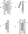
- FIG. 1 is a schematic cross-sectional view showing the structure of a fiber sheet according to an embodiment of the present invention.
- FIG. 2 is a schematic cross-sectional view showing the structure of a fiber sheet according to another embodiment of the present invention.
- FIG. 3 is a schematic cross-sectional view showing the structure of the fiber sheet according to still another embodiment of the present invention.
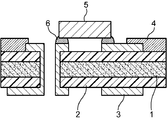
- FIG. 4 is a schematic cross-sectional view showing the configuration of an electronic substrate according to an embodiment of the present invention.
- FIG. 5 is a schematic cross-sectional view showing an example in which a conductor layer is also formed inside the fiber sheet in the fiber sheet according to the embodiment of the present invention.
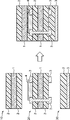
- FIG. 6 is a schematic cross-sectional view showing a manufacturing process of the fiber sheet in the embodiment.
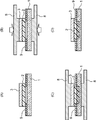
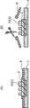
- FIG. 7 is a schematic cross-sectional view showing a manufacturing process of the fiber sheet with copper foil in the examples.
- FIG. 8 is a schematic cross-sectional view showing a manufacturing process of the circuit board 2 in the embodiment.
- the fiber sheet of the present invention can be used industrially. It is very advantageous.
- the fiber sheet according to the present embodiment includes a resin layer 2 containing a thermosetting resin and a fiber layer 1, can be stretched by 1% or more, and has an initial tensile elastic modulus of 1 MPa. It is characterized in that it is 10 GPa or less.
- the initial tensile elastic modulus means the elastic modulus when the sheet is stretched by 1%.
- the fact that the initial tensile elastic modulus is 1 MPa or more means that the fiber sheet of the present embodiment is a sheet capable of stretching at least 1% or more. More preferably, it is a sheet capable of stretching by 5% or more.
- the fiber sheet capable of stretching by 1% can be integrated with the fabric without impairing the texture of the fabric, and can provide an electronic substrate or a circuit board having high durability against expansion and contraction.
- the upper limit of extendability is not particularly limited, but 100% is sufficient.
- the restoring force is inferior and the original shape is not restored, which is not preferable. Further, if the initial tensile elastic modulus exceeds 10 GPa, the elasticity is inferior, and for example, when a fiber sheet is used for clothes, there is a problem that it is not comfortable to wear, which is not preferable.
- the more preferable initial tensile elastic modulus of the fiber sheet in the present embodiment is 5 MPa or more and 1 GPa or less, and more preferably 5 MPa or more and 500 MPa or less.
- the initial tensile elastic modulus in the present embodiment can be measured by a method of calculating the elastic modulus when the fiber sheet is cut to a predetermined size and pulled to 1% (elongation%) at a constant moving speed. it can.
- each reference numeral indicates the following: 1 fiber layer, 2 resin layer, 3 conductor layer (copper foil), 4 conductor layer (expandable positive conductive paste), 5 electronic parts, 6 solder. ..
- the resin layer of the fiber sheet in the present embodiment is not particularly limited as long as it contains a thermosetting resin and the initial tensile elastic modulus of the fiber sheet is within the above range.
- a thermosetting resin generally used as an elastic insulating layer of an electronic base material can be used as the resin layer of the present embodiment.
- thermosetting resin By including a thermosetting resin in the resin layer of the present embodiment, it exhibits high heat resistance, and for example, it is a resin layer in which melting and thermal decomposition are suppressed even in a high temperature atmosphere when mounting electronic components. Can be done.
- the resin layer may be formed on the entire surface of one side or both sides of the fiber layer, but as shown in FIG. 1, it is formed on the surface of at least a part of at least one side of the fiber layer. It may have been.
- the resin layer 2 may be impregnated in the fiber layer 1.
- the resin layer 2 may be impregnated in the fiber layer 1.
- the entire resin layer 2 not the entire resin layer 2 but a part thereof may be impregnated into at least a part of one side of the fiber layer 1.
- a form in which the resin layer is impregnated on both sides of the fiber layer is naturally included in the present invention.
- the thickness of the resin layer is not particularly limited and can be appropriately set depending on the intended use. For example, if the thickness is 50 ⁇ m to 5000 ⁇ m, handleability and optics are available. It is preferable from the viewpoint of characteristics and wearability.
- thermosetting resin of the present embodiment contains at least an epoxy resin. As a result, it is considered that heat resistance can be obtained more reliably.
- thermosetting resin and the resin layer have a glass transition temperature of 60 ° C. or lower.
- the fiber sheet can be further given flexibility. It is not necessary to set a lower limit value for the glass transition temperature, but it is preferably ⁇ 40 ° C. or higher in order to avoid stickiness at room temperature.
- thermosetting resin can be stretched by 1% or more.
- the fiber sheet can be stretched by 1% or more.
- thermosetting resin preferably has an initial tensile elastic modulus of 1 MPa or more and 10 GPa or less. As a result, the initial tensile elastic modulus of the fiber sheet becomes 1 MPa or more and 10 GPa or less.
- the resin composition used for the resin layer of the present embodiment is not particularly limited as long as it has the above-mentioned characteristics.
- the resin composition of the present embodiment preferably contains a polyrotaxane resin or an epoxy resin as a thermosetting resin, and particularly preferably contains an epoxy resin. Further, it preferably contains a curing agent. As a result, it is possible to obtain a fiber sheet having sufficient heat resistance and capable of withstanding the heat when mounting components in the reflow process. Further, by laminating the uncured resin composition with the fiber layer and then curing the resin composition, it becomes easy to integrate the resin layer with the fiber layer.
- a resin composition containing polyrotaxane (A), a thermosetting resin (B) and a curing agent (C) can be mentioned.
- A polyrotaxane
- B thermosetting resin
- C curing agent
- polyrotaxane (A) examples include polyrotaxane as described in Japanese Patent No. 4482633 or International Publication No. WO2015 / 052853 pamphlet.
- Commercially available products may be used, and specifically, Serum Superpolymer A1000 manufactured by Advanced Soft Materials Co., Ltd. can be used.
- thermosetting resin (B) examples include thermosetting resins such as epoxy resin, phenol resin, polyimide resin, urea resin, melamine resin, unsaturated polyester, and urethane resin without particular limitation. Of these, it is preferable to use an epoxy resin.
- the epoxy resin examples include bisphenol A type epoxy resin, bisphenol F type epoxy resin, bisphenol S type epoxy resin, aralkyl epoxy resin, phenol novolac type epoxy resin, alkylphenol novolac type epoxy resin, and biphenol type epoxy.
- examples thereof include resins, naphthalene-type epoxy resins, dicyclopentadiene-type epoxy resins, epoxidized products of condensates of phenols and aromatic aldehydes having phenolic hydroxyl groups, triglycidyl isocyanurate, alicyclic epoxy resins and the like. These may be used individually by 1 type or in combination of 2 or more type depending on the situation.
- an epoxy resin containing two or more epoxy groups in one molecule and having a molecular weight of 500 or more is preferably exemplified.
- an epoxy resin a commercially available epoxy resin may be used, for example, JER1003 (manufactured by Mitsubishi Chemical Co., Ltd., molecular weight 1300, bifunctional), EXA-4816 (manufactured by DIC, molecular weight 824, bifunctional), YP50 (Nippon Steel). Sumitomo Metals Chemical Co., Ltd., molecular weight 60,000 to 80,000, bifunctional) and the like.
- the epoxy resin has an alkylene oxide-modified modifying group having 2 to 3 carbon atoms and the modifying group is contained in 1 mol molecule of the epoxy in an amount of 4 mol or more, and has an epoxy group of 2 mol or more.
- the thermosetting resin (B) and the curing agent (C) which are epoxy resins having an epoxy equivalent of 450 eq / mol or more, the cured product is a resin having the extensibility and the tensile elasticity. It is possible to obtain a composition.
- epoxy resin examples include propylene oxide-added bisphenol A type epoxy resin (ADEKA EP4003S), ethylene oxide-added hydroxyphenylfluorene type epoxy resin (Osaka Gas Chemicals EG-280), and the like. Be done.
- a resin composition containing a single component of polyrotaxane (A) and a thermosetting resin (B) and a curing agent (C) may be used, but both components ((A) and (B)) may be used. It is preferable to prepare a resin composition containing the curing agent (C) because the cured product can easily obtain the resin composition having the extensibility and the tensile elastic modulus. Further, one type of epoxy resin as described above may be used alone, or two or more types may be used in combination.
- the curing agent (C) is not particularly limited as long as it works as a curing agent for the thermosetting resin (B).
- examples of the epoxy resin that can be preferably used as a curing agent include phenol resins, amine compounds, acid anhydrides, imidazole compounds, sulfide resins, and dicyandiamides.
- a light / ultraviolet curing agent, a thermal cation curing agent, and the like can also be used. These may be used individually by 1 type or in combination of 2 or more type depending on the situation.
- the resin composition may contain a curing accelerator, if necessary. Examples of the effect promoter include imidazole compounds and the like.
- a cross-linking agent may be further added, and such a cross-linking agent is at least a part of the cyclic molecule of the polyrotaxane. It can be used without particular limitation as long as it can form a structure that crosslinks with (at least one reactive group of the cyclic molecule of polyrotaxane). Specific examples thereof include isocyanate and cyanuric chloride.
- the ratio of each component in the resin composition is not particularly limited as long as the effects of the present invention can be exhibited, but for example, when all the components (A), (B) and (C) are contained, the above.
- the polyrotaxane (A) is about 10 to 80 parts by mass, more preferably about 30 to 50 parts by mass;
- the thermosetting resin (B) is 10 to 89.9 parts by mass.
- the curing agent (C) is about 0.1 to 30 parts by mass, more preferably about 0.1 to 20 parts by mass.
- the resin composition of the present embodiment contains an isocyanate resin as a cross-linking agent
- 0 to 50 parts by mass of the isocyanate resin can be added to the polyrotaxane (A), and further, 10 to 40 parts by mass. It is preferable to add it.
- the component (B) and the component (C) are contained and the component (A) is not contained, the total amount of the resin composition is 100 parts by mass, and the thermosetting resin (B) is 50 to 99 parts by mass, more preferably. About 60 to 80 parts by mass;
- the curing agent (C) is about 1 to 50 parts by mass, more preferably about 1 to 40 parts by mass.
- the resin composition according to the present embodiment contains other additives such as a curing catalyst (curing accelerator), a flame retardant, a flame retardant aid, a leveling agent, and a colorant as long as the effects of the present invention are not impaired. Etc. may be contained as needed.
- the method for preparing the resin composition of the present embodiment is not particularly limited. For example, first, an epoxy resin, a curing agent, a cross-linking agent, a thermosetting resin and a solvent are mixed so as to be uniform, and the resin of the present embodiment is prepared. The composition can be obtained.
- the solvent used is not particularly limited, and for example, toluene, xylene, methyl ethyl ketone, acetone and the like can be used. These solvents may be used alone or in combination of two or more. Further, if necessary, an organic solvent for adjusting the viscosity and various additives may be blended.
- the resin layer is, for example, the fiber layer described later is immersed in the resin composition as described above, the resin composition is applied to the fiber layer, or the resin composition in the form of a film. Is formed by sticking to a fiber layer.
- the method for applying the resin composition is not particularly limited, and examples thereof include a bar coater, a comma coater, a die coater, a roll coater, and a gravure coater.
- the impregnation can be repeated a plurality of times as needed. Further, at this time, it is also possible to repeat impregnation using a plurality of resin varnishes having different compositions and concentrations to finally adjust the desired composition and amount of resin.
- the organic solvent is volatilized from the resin layer (A stage) containing the resin composition before curing containing the organic solvent by heating to reduce or remove the organic solvent. Can be done.
- the fiber layer coated or impregnated with the resin composition (resin varnish) is heated under desired heating conditions, for example, 80 to 120 ° C. for 1 to 120 minutes to reduce or remove the organic solvent in an uncured or semi-cured state.
- the resin layer in the state (B stage) is obtained.
- the B stage of the resin composition that is, the uncured state (uncured product) or the semi-cured state (semi-cured product) is a state in which the resin composition can be further cured.
- the semi-curing state includes a state between the time when the viscosity starts to increase and the time before it is completely cured.
- the resin layer can be cured by further heating.
- the fiber layer coated or impregnated with the resin composition (resin varnish) is heated under desired heating conditions, for example, 80 to 200 ° C. for 1 to 120 minutes to obtain a cured resin layer (C stage).
- the C stage of the resin composition that is, the cured state (cured product) is a state in which the curing reaction proceeds and the resin is crosslinked so that it does not melt even when heated. As expected.
- the resin composition is previously coated on a desired plastic film, metal foil, or the like, and the resin composition before curing (A stage) containing an organic solvent is used.
- a resin layer containing a substance or a resin layer in an uncured or semi-cured state (B stage) is obtained by heating at a desired heating condition, for example, 80 to 120 ° C. for 1 to 120 minutes. It is obtained by bonding this to the fiber layer and fixing it to the fiber layer by external energy such as pressure and heat. It may be a resin layer in an uncured or semi-cured state (B stage), or may be a resin layer in a cured state (C stage) by further curing the resin layer by heating.
- the fiber layer in the present embodiment is not particularly limited, and for example, a fiber layer composed of a woven fabric, a knitted fabric, a braid, a non-woven fabric, or a combination thereof can be used.
- the fiber layer may be a unidirectionally arranged woven fabric. Thereby, there is an advantage that a fiber sheet having elasticity only in a desired direction can be obtained.
- the above-mentioned woven fabric, knitted fabric, braid, non-woven fabric or the like is preferably composed of plant fiber, animal fiber, synthetic fiber, semi-synthetic fiber, regenerated fiber, inorganic fiber or a combination thereof. ..
- the fiber layer may have an initial tensile elastic modulus of 1 MPa or more and 1 GPa or less.
- the elastic modulus of the fiber layer is preferably about 0.01 MPa to 1 GPa
- the elongation rate is preferably about 1% or more and 1000% or less, and more preferably 5% or more and 1000% or less. That is, the fiber layer of the present embodiment does not include a base material such as glass cloth having almost no extensibility.
- examples of the fibers used in the fiber layer of the present embodiment include fibers generally used as a cloth. That is, examples of plant fibers include seed hair fibers such as cotton and kapok, bark fibers such as flax, timer, choma, jute, mitsumata, and mulberry, and leaf vein fibers such as Manila asa and sisal asa. Examples of animal fibers include wool, angora, cashmere, mohair, camels, alpaca, silk and the like. The animal fiber may contain leather, and examples thereof include mammals such as cows, pigs, horses, sheep and goats, reptiles such as crocodile and snake, birds such as ostriches, and fish such as sharks.
- plant fibers include seed hair fibers such as cotton and kapok, bark fibers such as flax, timer, choma, jute, mitsumata, and mulberry, and leaf vein fibers such as Manila asa and sisal asa.
- Examples of animal fibers
- Synthetic fibers include nylon fiber, aramid fiber, vinylon fiber, polyvinylidene chloride synthetic fiber, polyvinyl chloride synthetic fiber, polyester synthetic fiber, polyacrylonitrile synthetic fiber, polyethylene synthetic fiber, polypropylene synthetic fiber, polyurethane. Examples include synthetic synthetic fibers and polylactic fibers. Synthetic fibers may include artificial leather and synthetic leather. Examples of the semi-synthetic fiber include acetate fiber and the like. Examples of the regenerated fiber include viscose fiber and cuprammonium fiber. Examples of the inorganic fiber include glass fiber, carbon fiber, metal fiber and the like.
- the cloth used for clothing when used for wearable devices, can also be used as the fiber of the fiber layer.
- it may be a fabric used for a tent, a truck bed, or the like. As a result, it is possible to integrate the fabric and various devices into the fabric used in various situations.
- the thickness of the fiber layer is not particularly limited and can be appropriately set depending on the intended use. For example, if the thickness is 50 ⁇ m to 5000 ⁇ m, the fiber sheet has elasticity and handling. It is preferable from the viewpoint of sex.
- the fiber sheet of the present embodiment may be provided with a conductor layer on one side, both sides, or inside.
- the conductor layer include wiring formed of a metal foil or a conductive composition, an ultrathinly coated conductive layer, a conductive thread, a metal molded product, and the like.
- the metal foil is not particularly limited, and examples thereof include copper foil (plating), aluminum foil, stainless foil, etc., and these metal foils are metal foils surface-treated with a silane coupling agent or the like. You may.
- a conductor layer using a metal foil When forming a conductor layer using a metal foil, one or a plurality of the above-mentioned fiber sheets are laminated, and then a metal foil such as a copper foil is laminated on both upper and lower sides or a part or the entire surface of one side thereof and heated. By press-molding and laminating and integrating, a double-sided metal foil-covered or single-sided metal foil-covered laminate can be produced.
- one or more fiber sheets are laminated, and a metal foil such as copper foil coated with a resin layer is laminated on both upper and lower sides or a part or the entire surface thereof, and this is heat-pressed and laminated. By integrating, a double-sided metal foil-covered or single-sided metal foil-covered laminate can be produced.
- one or more fiber layers that do not contain a resin layer are laminated, and a metal foil such as copper foil coated with a resin layer on both upper and lower surfaces or a part or the entire surface thereof is laminated, and this is heated and pressed.
- a metal foil such as copper foil coated with a resin layer on both upper and lower surfaces or a part or the entire surface thereof is laminated, and this is heated and pressed.
- a laminated body of double-sided metal foil or single-sided metal foil can be produced.
- a conductor layer (wiring) can be provided as a circuit on the surface of the laminate containing the fiber sheet of the present embodiment.
- the metal foil is formed into a circuit by etching, it is preferable to mask the fiber layer so that it is not immersed in the etching solution.
- a cover film a solvent-resistant plastic film such as polyimide is provided with an opening in a desired shape, and a resin layer covered with a single-sided metal foil is attached so as to cover the opening.
- a resin layer covered with a single-sided metal foil is attached so as to cover the opening.
- This laminate is attached to a plastic plate with tape or the like so that the fiber layer does not come into contact with the etching solution, and etching processing is performed.
- a resin layer is provided in the shape of the opening, and a metal foil circuit is formed on the surface thereof.
- examples of the method for forming a circuit include a semi-additive method (SAP: Semi Adaptive Process) and a modified semi-additive method (MSAP: Modified Semi Adaptive Process). Further, by laminating these with a resin layer in an uncured or semi-cured state, or a fiber sheet containing the resin layer, a laminated body containing a conductor layer can be produced.
- SAP Semi Adaptive Process
- MSAP Modified Semi Adaptive Process
- a copper foil When a copper foil is further used as the conductor layer in the fiber sheet of the present embodiment, it has heat resistance and the solder gets wet well, so that it is possible to mount the parts in the reflow process, and the operation reliability is improved. It is possible to provide expensive fabric devices and the like.
- parts can be mounted on both sides by various means, or the mounted parts can be further included.
- the conductor layer of the present embodiment may be formed of the conductive composition.
- the conductive composition of the present embodiment is preferably a conductive composition having elasticity. As a result, it is possible to obtain a fabric device or the like that does not hinder the extensibility and elasticity of the fiber sheet and has excellent operation reliability.
- An example of the elastic conductive composition is specifically shown below.
- the conductive composition contains a resin (D) serving as a stretchable binder, a curing agent (E) that reacts with the resin (D), and a conductive filler (F), and the resin.
- (D) has a functional group having a functional group equivalent of 400 g / eq or more and 10000 g / eq or less, and the cured product of the resin (D) and the conductive composition has a glass transition temperature (Tg).
- Tg glass transition temperature
- the softening point is 40 ° C or less, or the elastic conductivity at 30 ° C is less than 1.0 GPa
- the conductive filler (F) has an intrinsic volume resistivity at room temperature of 1 ⁇ 10 -4 ⁇ .
- Examples thereof include a resin composition composed of a conductive substance having a size of cm or less.
- Examples of the functional group include an epoxy group, a vinyl group, a (meth) acryloyl group, a hydroxyl group, a carboxyl group, an amino group, an alkoxy group, and a carbonyl group.
- the component of the molecular structure of the resin (D) may be a single component, or a plurality of types may be used in combination at an arbitrary ratio. It is preferable that the molecular structure of the resin (D) is a molecular structure containing at least one selected from (meth) acrylic acid ester, styrene, and nitrile as a component. As specific examples, epoxy-modified (meth) acrylic acid ester, hydroxyl group-modified (meth) acrylic acid ester, carboxyl group-modified (meth) acrylic acid ester and the like are preferably exemplified.
- the resin (D) preferably has a weight average molecular weight of 50,000 or more.
- the upper limit of the weight average molecular weight is not particularly limited, but when the molecular weight exceeds 3 million, the viscosity may increase and the handleability may decrease, which is preferable as the weight average molecular weight range of the resin (D). Is 50,000 or more and 3 million or less, more preferably 100,000 or more and 1 million or less.
- curing agent (E) various curing agents can be used without particular limitation as long as they have reactivity with the resin (D) as described above.
- specific examples of the curing agent (E) include radical generators such as imidazole compounds, amine compounds, phenol compounds, acid anhydride compounds, isocyanate compounds, mercapto compounds, onium salts, and peroxides, and light. Examples include acid generators.
- the conductive filler (F) is made of a conductive substance having an intrinsic volume resistivity of 1 ⁇ 10 -4 ⁇ ⁇ cm or less at room temperature.
- the volume resistivity of the conductive composition is approximately 1 ⁇ 10 -3 ⁇ ⁇ , although it depends on the blending amount. It is cm to 1 x 10 -2 ⁇ ⁇ cm. Therefore, in the case of a circuit, the resistance value becomes high and the power loss becomes large.
- Examples of the conductive substance include simple substances composed of metal elements such as silver, copper, and gold, and oxidation containing these elements. Examples include compounds such as substances, nitrides, carbides and alloys.
- a conductive or semi-conductive conductive auxiliary agent may be added to the conductive composition for the purpose of further improving the conductivity.
- a conductive or semi-conductive auxiliary agent a conductive polymer, an ionic liquid, carbon black, acetylene black, carbon nanotubes, an inorganic compound used as an antistatic agent, or the like can be used, and only one kind can be used. It may be used or two or more types may be used at the same time.
- the conductive filler (F) preferably has a flat shape, and preferably has a thickness and an aspect ratio in the in-plane longitudinal direction of 10 or more.
- the aspect ratio is 10 or more, not only the surface area of the conductive filler with respect to the mass ratio becomes large and the efficiency of conductivity increases, but also the adhesion with the resin component is improved and the elasticity is improved. ..
- the aspect ratio is 1000 or less, it is preferably 10 or more and 1000 or less, and more preferably 20 or more and 500 or less, from the viewpoint of ensuring better conductivity and printability.
- Examples of the conductive filler having such an aspect ratio include a conductive filler having a tap density of 6.0 g / cm 3 or less measured by the tap method. Further, when the tap density is 2.0 g / cm 3 or less, the aspect ratio becomes larger, which is more preferable.
- the blending ratio of the conductive filler (F) in the conductive composition is 40 to 95% by mass in terms of mass ratio. It is preferable in terms of conductivity, cost, and printability, and more preferably 60 to 85% by mass.
- the particle size of the conductive filler (F) of the present embodiment is not particularly limited, but average particles measured by a laser light scattering method from the viewpoint of printability during screen printing and appropriate viscosity in kneading of the formulation.
- the diameter (particle size at a cumulative volume of 50%; D50) is preferably 0.5 ⁇ m or more and 30 ⁇ m or less, and more preferably 1.5 ⁇ m or more and 20 ⁇ m or less.
- the conductive filler (F) is preferably a conductive filler whose surface is coupled.
- the conductive composition of the present embodiment may contain a coupling agent.
- the coupling agent to be added to the conductive composition or for coupling the conductive filler can be used without particular limitation as long as it is adsorbed on the filler surface or reacts with the filler surface.
- Examples thereof include silane coupling agents, titanate-based coupling agents, and aluminum-based coupling agents.
- the amount of the coupling agent added is preferably about 1% by mass to 20% by mass with respect to the entire conductive composition.
- the ratio of each component in the conductive composition is not particularly limited as long as the effect of the present invention can be exhibited, and the compounding ratio of the (F) resin: the (G) curing agent is the resin and the curing. Depending on the type of agent, it can be appropriately determined in consideration of the equivalent ratio and the like.
- additives and the like can be added to the conductive composition depending on the purpose.
- additives include elastomers, surfactants, dispersants, colorants, fragrances, plasticizers, pH adjusters, viscosity regulators, ultraviolet absorbers, antioxidants, lubricants and the like.
- the method for preparing the conductive composition is not particularly limited as long as the conductive composition can be produced.
- a method for preparing the conductive composition for example, the above-mentioned resin component, the conductive filler, a curing agent, a dispersant and the like, if necessary, and a solvent are mixed and stirred so as to be uniform, and the above-mentioned Examples thereof include a method for obtaining a conductive composition.
- the mixing / stirring method is not particularly limited, and a high-shear dispersion device such as a rotation-revolution mixer or a three-roll mill is preferably used. Further, vacuum defoaming may be performed.
- a -Conductor layer using the conductive composition By applying or printing the conductive composition of the present embodiment on the resin layer of the fiber sheet as described above, a coating film of the conductive composition is formed, which is desired. It is possible to form a conductor layer such as wiring (conductive pattern).
- the conductive pattern or the like formed by the wiring can be formed on the surface of the fiber sheet by the following steps. That is, first, a coating film is formed by applying or printing the conductive composition of the present embodiment on the resin layer, and volatile components contained in the coating film are removed by drying. The resin (D) and the curing agent (F) are cured by the subsequent curing steps such as heating, electron beam, and light irradiation, and the coupling agent and the conductive filler (F) are combined with the resin (D). By the step of reacting the curing agent (F) with the curing agent (F), a conductive pattern made of elastic wiring can be formed. Each condition in the curing step and the reaction step is not particularly limited, and may be appropriately set depending on the type of resin, curing agent, filler, etc. and the desired form.
- the step of applying the conductive composition of the present embodiment on the substrate is not particularly limited, and for example, a coating method such as an applicator, a wire bar, a comma roll, a gravure roll, a screen, a flat plate offset, a flexo, an inkjet, or a stamping. , Dispens, squeegee, etc. can be used.
- the conductor layer may be formed inside the fiber sheet.
- the fiber sheet 20 on which the conductive pattern is formed is subjected to.
- the layers are integrated.
- the elastic wiring can be formed inside the fiber sheet.
- conductive fillers conductive polymers, ionic liquids, carbon black, acetylene black, carbon nanotubes, inorganic compounds used for antistatic agents, etc. are dispersed in a solvent, and liquid metals are used as fibers.
- a conductive layer or wiring may be formed by coating, printing, or the like on both sides or a part or the entire surface of the sheet. Further, a plurality of conductive layers may be connected by sewing with a conductive thread. Further, a plurality of conductive layers may be connected by a metal molded product such as a rivet or a snap button.
- the laminate may include a plurality of conductor layers, but the plurality of conductor layers are plated as described above. It may be conducted by (metal foil such as copper foil) or a conductive composition as described above.
- the conductive composition used for conduction preferably does not contain a solvent. As a result, there is an advantage that it can be used as a multi-layer circuit board.
- circuit board of the present embodiment is characterized by using a fiber sheet provided with the conductor layer or a laminate as described above.
- the present invention also includes an electronic substrate including a fiber sheet as described above or a laminate as described above and an electronic component.
- the structure and form thereof are not particularly limited, but for example, in the case of an electronic substrate as shown in FIG. 4, resin layers 2 are formed on both sides of the fiber layer 1, and the surface of the resin layer 2 and the fiber sheet A circuit is formed inside the metal foil (copper foil) 3. Further, the circuit made of the metal foil 3 is conducted by the conductive composition 4 between the circuit and the circuit, and electronic components are mounted on the circuit via the solder 6.
- the circuit board and the electronic board of the present embodiment can be manufactured by a known method using the above-mentioned fiber sheet or laminate. Since the fiber sheet of the present embodiment has heat resistance, it is possible to mount electronic components by reflow as described above. In addition to reflow, various heating means such as welding, soldering iron, induction heating, and microwave can be used. Since the resin layer has heat resistance even if it is a means capable of local heating, it does not melt or thermally decompose. It can also be implemented by ACF or the like.
- a circuit board or an electronic board by forming an element by using various printing techniques, for example, without using a conventional electronic component. Even if a heating process is required in the process of manufacturing these, the resin layer has heat resistance, so that it does not melt or thermally decompose.
- the laminate or circuit board of the present embodiment having such a conductor layer, or the electronic board provided with electronic components is flexible and has elasticity and flexibility. Therefore, for example, a bendable electronic paper or an organic EL It is very suitable as an electronic material used for displays, solar cells, RFID, pressure sensors and the like.
- the fiber layer which is the fabric (fabric, etc.)
- the electronic device it is also excellent as a wearable device, and is also suitable for applications such as outdoor advertising.
- the fiber sheet according to one aspect of the present invention includes a resin layer containing a thermosetting resin and a fiber layer, and is characterized in that the initial tensile elastic modulus is 1 MPa or more and 1 GPa or less. With such a configuration, it is possible to provide a fiber sheet having a resin layer having excellent heat resistance and elasticity, which can be used for various purposes.
- thermosetting resin contains at least an epoxy resin. As a result, it is considered that higher heat resistance can be obtained.
- the glass transition temperature of the thermosetting resin is preferably 60 ° C. or lower, which can further impart flexibility to the fiber sheet.
- the fiber layer is composed of a woven fabric, a knitted fabric, a braid, a non-woven fabric, or a combination thereof.
- the fiber layer is a unidirectionally arranged woven fabric. This has the advantage that a fiber sheet having elasticity only in a desired direction can be obtained.
- the fiber layer is composed of plant fiber, animal fiber, synthetic fiber, semi-synthetic fiber, regenerated fiber, inorganic fiber or a combination thereof. This has the advantage that it is inexpensive and easily available, and at the same time, it is generally used as a fabric and can be used as a fabric device without discomfort.
- thermoplastic resin (thermoplastic resin) (Fiber layer) -Polyester fabric (Ponte Double Knit PDRR-002) -Nylon fabric (Rayon Spandex Jersey Knit 0451725) -Cotton fabric (Telio Organic Cotton Jersey Knit 0462839) -Wool fabric (Wool Novelty Sitting 0649007) ⁇ Acetate fabric (A8700) ⁇ Cupra fabric (LOISIR AK650) ⁇ Paper (OK Clean RN) ⁇ Cowhide / artificial leather (Roel II) ⁇ Carbon fiber fabric (Credit card cloth P-200)
- Resin varnishes 1 to 5 were adjusted with each component as the blending ratio shown in Table 1. After static defoaming, the resin varnish was applied to a PET film (SP-PET O1 manufactured by Mitsui Chemicals Tohcello Corporation) using a bar coater. Then, it was heated in an oven at 80 ° C. for 24 hours, and further heated at 160 ° C. for 5 minutes to obtain a semi-cured resin film.
- SP-PET O1 manufactured by Mitsui Chemicals Tohcello Corporation
- the resin layer 2 is 100 mm square with the PET film 7 attached to the center of the fiber layer 1 (polyester fabric (Ponte Double Knit PDRR-002)) cut into 300 mm square.
- a cut semi-cured resin film or a cured resin film was placed on the sheet and sandwiched between stainless steel plates 8. It was set in a vacuum heating press (ASFV-25, manufactured by Shinto Metal Industry Co., Ltd.) and heated at 160 ° C. for 1 hour under 1 MPa pressurization. Then, the PET film 7 was peeled off to obtain a fiber sheet provided with the fiber layer 1 and the resin layer 2.
- a silver paste was printed on the resin layer surface of the fiber sheet using a screen plate, and a wiring made of silver paste was formed on the resin layer of the fiber sheet to obtain a circuit board 1.
- a polyimide film 9 (manufactured by Ube Industries, Ltd., Upirex S, 25 ⁇ m) was cut into a 300 mm square, and a 100 mm square square film was further cut out from the central portion thereof.
- the polyimide film 9 was placed on the fiber layer 1 cut into 300 mm square, and further cut into 150 mm square so as to cover the cut out portion of the 100 mm square square film of the polyimide film 9, and the resin layer 2 and the conductor layer.
- a laminate obtained by placing a copper foil with a semi-curing resin or a copper foil with a cured resin provided with (copper foil) 3 in a direction in which the resin layer 2 is on the polyimide film side is sandwiched between two stainless plates 8. It is.
- the laminate was set in a vacuum heating press (ASFV-25, manufactured by Shinto Metal Industry Co., Ltd.) and heated at 160 ° C. for 1 hour under 1 MPa pressurization to obtain a fiber sheet with copper foil.
- ⁇ Manufacturing method of circuit board 2> As shown in FIG. 8, a dry film resist is laminated on the copper foil surface of the fiber sheet with copper foil, developed by photolithography, etched with copper foil, and a conductor layer is placed on the resin layer of the fiber sheet with copper foil. A wiring 10 made of (copper foil) 3 was formed. Then, the polyimide film 9 was removed to obtain a circuit board 2.
- Distortion (r) x / x0 (x is the moving distance of the gripping tool, x0 is the distance between the initial gripping tools)
- Stress ( ⁇ ) F / (d ⁇ l) (F is the test force, d is the film thickness, l is the width of the test piece)
- each of the resin varnishes 1 to 5 shown in Table 1 was used to prepare the fiber sheets 1 to 16, and the semi-cured or cured resin films 1 to 5 and various fiber layers shown in Table 3 were combined to prepare the fiber sheets 1 to 16. ..
- each of the obtained fiber sheets was cut to 50 mm * 100 mm so that the entire surface contained a resin layer, and attached to a universal testing machine (AGS-X manufactured by Shimadzu Corporation).
- the test was performed at the initial grip distance: 50 mm and the tensile speed: 100 mm / min, and from all the stress ( ⁇ ) data corresponding to the strain (r) of 0 to 0.01, the minimum square method was used to determine r- ⁇ .
- the initial tensile elastic modulus was calculated by obtaining the inclination. The results are shown in Table 3.
- Distortion (r) x / x0 (x is the moving distance of the gripping tool, x0 is the distance between the initial gripping tools)
- Stress ( ⁇ ) F / (d ⁇ l) (F is the test force, d is the film thickness, l is the width of the test piece)
- the measurement results of the fiber sheets 1 to 16 were the same for the fiber sheets with copper foil produced by using the same resin layer and the fiber layer.
- the fiber sheet of the present invention has a wide range of industrial applicability in technical fields such as wearable devices, patch devices, flexible display devices, optical fields, electronic fields, adhesive fields, and medical fields.
Abstract
One aspect of the present invention relates to a fiber sheet: which is provided with a fiber layer and a resin layer containing a thermosetting resin; is stretchable by 1% or greater; and has an initial tensile modulus of 1 MPa to 1 GPa.
Description
本発明は、繊維シート、並びに、それを用いた積層体、回路基板および電子基板に関する。
The present invention relates to a fiber sheet, and a laminate, a circuit board, and an electronic board using the fiber sheet.
エレクトロニクス分野、特にセンサ、ディスプレイ、ロボット用人工皮膚などの様々なインターフェースに用いられるデバイスや導電材料に対し、装着性や形状追従性の要求が高まっている。用途に応じて、曲面や凹凸面などに配置したり自由に変形させたりすることが可能な柔軟なデバイスが要求されつつある。
There is an increasing demand for wearability and shape-following properties for devices and conductive materials used in various interfaces such as sensors, displays, and artificial skin for robots in the electronics field. There is an increasing demand for flexible devices that can be arranged on curved surfaces or uneven surfaces or freely deformed according to the application.
そのような柔軟なデバイス(例えば、ウェラブルデバイス等)に使用される伸縮性導電シートがすでに報告されつつある。例えば、伸縮性樹脂を含む導電性ペーストで伸縮性導体層を作製し、ホットメルトシートを貼り合わせて、生地に接触させてホットプレスすることによって、伸縮性電極シートを製造し、生体情報計測用インターフェースを得ることが報告されている(特許文献1)。また、プラスチック糸改良構造において、導電線を熱硬化性高分子接着剤内に包み、当該接着剤に熱をかけて固化させ、紙や布体などのベース層と結合させることも報告されている(特許文献2)。
Stretchable conductive sheets used in such flexible devices (eg, wearable devices, etc.) are already being reported. For example, a stretchable conductor layer is prepared with a conductive paste containing a stretchable resin, a hot melt sheet is attached to the fabric, and the stretchable electrode sheet is manufactured by contacting the fabric with hot pressing to produce a stretchable electrode sheet for biometric information measurement. It has been reported to obtain an interface (Patent Document 1). It has also been reported that in a plastic thread improved structure, a conductive wire is wrapped in a thermosetting polymer adhesive, and the adhesive is heated to solidify and bonded to a base layer such as paper or cloth. (Patent Document 2).
しかしながら、前記特許文献1記載の技術のように、ホットメルトシートを使用すると、通常のホットメルトシートには耐熱性がないため、リフローはんだ付け等による部品実装を行うことができない。また、シートが裂けるおそれもある上に、ホットメルトシートによる貼り合わせでは、導体層と生地との一体感が十分に得られないという問題もある。前記特許文献2記載の技術においても、熱硬化性高分子接着剤で構成される層が裂けるという不具合が考えられる。さらに、こちらも熱硬化性高分子接着剤を熱によって固化させてベース層に結合させるか、もしくは、さらにベース層に粘性面を設けて、そこへ熱硬化性高分子接着剤を結合させているが、この手法でも布体などのベース層と、導電線を内包する接着剤層との一体感は十分に得られない。
However, when a hot melt sheet is used as in the technique described in Patent Document 1, since a normal hot melt sheet does not have heat resistance, it is not possible to mount parts by reflow soldering or the like. Further, there is a possibility that the sheet may be torn, and there is also a problem that a sufficient sense of unity between the conductor layer and the fabric cannot be obtained by bonding with a hot melt sheet. Also in the technique described in Patent Document 2, there is a problem that the layer made of the thermosetting polymer adhesive is torn. Further, here as well, the thermosetting polymer adhesive is solidified by heat and bonded to the base layer, or a viscous surface is further provided on the base layer and the thermosetting polymer adhesive is bonded thereto. However, even with this method, it is not possible to obtain a sufficient sense of unity between the base layer such as a cloth and the adhesive layer containing the conductive wire.
本発明は、このような実情に鑑みてなされたものであり、様々な用途に使用できる、耐熱性と伸縮性に優れた樹脂層を有する繊維シートを提供することを課題とする。
The present invention has been made in view of such circumstances, and an object of the present invention is to provide a fiber sheet having a resin layer having excellent heat resistance and elasticity, which can be used for various purposes.
本発明者等は、鋭意検討した結果、下記構成の導電性組成物によって上記課題を解消し得ることを見出し、かかる知見に基づいて更に検討を重ねることによって本発明を完成した。
As a result of diligent studies, the present inventors have found that the above-mentioned problems can be solved by a conductive composition having the following constitution, and have completed the present invention by conducting further studies based on such findings.
すなわち、本発明の一つの局面に関する繊維シートは、熱硬化性樹脂を含む樹脂層と、繊維層とを備え、1%以上の伸長が可能であり、初期引張弾性率が1MPa以上10GPa以下であることを特徴とする。
That is, the fiber sheet according to one aspect of the present invention includes a resin layer containing a thermosetting resin and a fiber layer, can be stretched by 1% or more, and has an initial tensile elastic modulus of 1 MPa or more and 10 GPa or less. It is characterized by that.
さらに、本発明の他の局面に関する積層体は、上記繊維シートが2枚以上積層されていることを特徴とする。
Further, the laminate according to another aspect of the present invention is characterized in that two or more of the above fiber sheets are laminated.
また、本発明のさらに別の局面に関する回路基板は、上記繊維シートもしくは上記積層体を用いることを特徴とする。
Further, the circuit board according to still another aspect of the present invention is characterized by using the above fiber sheet or the above laminate.
本発明のさらに別の局面に関する電子基板は、上記繊維シートもしくは上記積層体と、電子部品とを備えることを特徴とする。
The electronic substrate according to still another aspect of the present invention is characterized by comprising the fiber sheet or the laminate and an electronic component.
本発明によれば、様々な用途に使用できる、耐熱性と伸縮性に優れた樹脂層を有する繊維シートを提供することできる。
According to the present invention, it is possible to provide a fiber sheet having a resin layer having excellent heat resistance and elasticity, which can be used for various purposes.
また、繊維層の一部または全部に耐熱性の高い樹脂層を設け、さらに、樹脂層表面または内部に導電層を設けることで、生地の風合いを損なうことなく生地と一体化し、伸縮に対する耐久性の高い電子基板や回路基板を提供することができる。
Further, by providing a highly heat-resistant resin layer on a part or all of the fiber layer and further providing a conductive layer on the surface or inside of the resin layer, it is integrated with the fabric without impairing the texture of the fabric and has durability against expansion and contraction. It is possible to provide a high-quality electronic board or circuit board.
さらには、前記特性を有することから、IoTやフレキシブル表示装置以外にも、光学分野、電子分野、接着分野、医療分野など様々な技術分野にも適用できるため、本発明の繊維シートは、産業利用上非常に有利である。
Furthermore, since it has the above-mentioned characteristics, it can be applied to various technical fields such as optical field, electronic field, adhesive field, medical field, etc. in addition to IoT and flexible display device. Therefore, the fiber sheet of the present invention can be used industrially. It is very advantageous.
以下、本発明に係る実施形態について具体的に説明するが、本発明は、これらに限定されるものではない。
Hereinafter, embodiments according to the present invention will be specifically described, but the present invention is not limited thereto.
<繊維シート>
本実施形態に係る繊維シートは、図1に示すように、熱硬化性樹脂を含む樹脂層2と、繊維層1とを備え、1%以上の伸長が可能であり、初期引張弾性率が1MPa以上10GPa以下であることを特徴とする。 <Fiber sheet>
As shown in FIG. 1, the fiber sheet according to the present embodiment includes aresin layer 2 containing a thermosetting resin and a fiber layer 1, can be stretched by 1% or more, and has an initial tensile elastic modulus of 1 MPa. It is characterized in that it is 10 GPa or less.
本実施形態に係る繊維シートは、図1に示すように、熱硬化性樹脂を含む樹脂層2と、繊維層1とを備え、1%以上の伸長が可能であり、初期引張弾性率が1MPa以上10GPa以下であることを特徴とする。 <Fiber sheet>
As shown in FIG. 1, the fiber sheet according to the present embodiment includes a
上記構成により、耐熱性と伸縮性に優れた樹脂層を有する繊維シートを提供することができる。
With the above configuration, it is possible to provide a fiber sheet having a resin layer having excellent heat resistance and elasticity.
本実施形態において、初期引張弾性率とは、前記シートを1%伸長させた時の弾性率を意味する。この初期引張弾性率が1MPa以上であるということは、本実施形態の繊維シートは、少なくとも1%以上の伸長が可能なシートである。より好ましくは5%以上の伸長が可能なシートである。1%の伸長が可能な繊維シートによって、生地の風合いを損なうことなく生地と一体化し、伸縮に対する耐久性の高い電子基板や回路基板を提供することができる。また、伸長可能な上限は、特に限定されないが、100%もあれば十分である。
In the present embodiment, the initial tensile elastic modulus means the elastic modulus when the sheet is stretched by 1%. The fact that the initial tensile elastic modulus is 1 MPa or more means that the fiber sheet of the present embodiment is a sheet capable of stretching at least 1% or more. More preferably, it is a sheet capable of stretching by 5% or more. The fiber sheet capable of stretching by 1% can be integrated with the fabric without impairing the texture of the fabric, and can provide an electronic substrate or a circuit board having high durability against expansion and contraction. The upper limit of extendability is not particularly limited, but 100% is sufficient.
前記初期引張弾性率が1MPa未満となると、復元力が劣り元の形状に戻らないといった不具合があるため好ましくない。また、前記初期引張弾性率が10GPaを超えると、伸縮性が劣り、例えば繊維シートを衣服に用いた場合、着心地がよくないといった不具合があるという点で好ましくない。本実施形態における繊維シートのより好ましい初期引張弾性率は5MPa以上、1GPa以下、さらに好ましくは5MPa以上、500MPa以下である。
If the initial tensile elastic modulus is less than 1 MPa, the restoring force is inferior and the original shape is not restored, which is not preferable. Further, if the initial tensile elastic modulus exceeds 10 GPa, the elasticity is inferior, and for example, when a fiber sheet is used for clothes, there is a problem that it is not comfortable to wear, which is not preferable. The more preferable initial tensile elastic modulus of the fiber sheet in the present embodiment is 5 MPa or more and 1 GPa or less, and more preferably 5 MPa or more and 500 MPa or less.
なお、本実施形態における初期引張弾性率は、繊維シートを所定のサイズにカットし、一定の移動速度で1%(伸長%)まで引っ張った時の弾性率を算出するという方法で測定することができる。
The initial tensile elastic modulus in the present embodiment can be measured by a method of calculating the elastic modulus when the fiber sheet is cut to a predetermined size and pulled to 1% (elongation%) at a constant moving speed. it can.
以下、本実施形態の繊維シートの各構成について詳細に説明する。なお、後述の説明に登場する図面において、各符号は以下を示す:1 繊維層、2 樹脂層、3 導体層(銅箔)、4 導体層(伸縮正導電ペースト)、5 電子部品、6 はんだ。
Hereinafter, each configuration of the fiber sheet of the present embodiment will be described in detail. In the drawings appearing in the description below, each reference numeral indicates the following: 1 fiber layer, 2 resin layer, 3 conductor layer (copper foil), 4 conductor layer (expandable positive conductive paste), 5 electronic parts, 6 solder. ..
(樹脂層)
本実施形態における繊維シートの樹脂層は、熱硬化性樹脂を含み、繊維シートの初期引張弾性率が上述の範囲となるような樹脂層であれば特に限定はない。電子基材の伸縮性絶縁層として一般に使用される熱硬化性樹脂を使用して、本実施形態の樹脂層とすることができる。本実施形態における樹脂層に熱硬化性樹脂を含むことで、高い耐熱性を示し、例えば電子部品を実装する時の高温の雰囲気化においても、溶融や熱分解を抑制された樹脂層とすることができる。 (Resin layer)
The resin layer of the fiber sheet in the present embodiment is not particularly limited as long as it contains a thermosetting resin and the initial tensile elastic modulus of the fiber sheet is within the above range. A thermosetting resin generally used as an elastic insulating layer of an electronic base material can be used as the resin layer of the present embodiment. By including a thermosetting resin in the resin layer of the present embodiment, it exhibits high heat resistance, and for example, it is a resin layer in which melting and thermal decomposition are suppressed even in a high temperature atmosphere when mounting electronic components. Can be done.
本実施形態の繊維シートにおいて、樹脂層は、繊維層の片側または両面の表面全体に形成されていてもよいが、図1に示すように、繊維層の少なくとも片面の少なくとも一部の表面に形成されていてもよい。
In the fiber sheet of the present embodiment, the resin layer may be formed on the entire surface of one side or both sides of the fiber layer, but as shown in FIG. 1, it is formed on the surface of at least a part of at least one side of the fiber layer. It may have been.
さらには、図2に示すように、樹脂層2が繊維層1に含浸されていてもよい。あるいは、図3に示すように、樹脂層2の全体ではなく、一部が、繊維層1の片面の少なくとも一部に含浸されていてもよい。なお、図示はしていないが、樹脂層が繊維層の両面に含浸されている(樹脂層の少なくとも一部が含浸されている場合も含む)形態も当然に本発明に包含される。
Further, as shown in FIG. 2, the resin layer 2 may be impregnated in the fiber layer 1. Alternatively, as shown in FIG. 3, not the entire resin layer 2 but a part thereof may be impregnated into at least a part of one side of the fiber layer 1. Although not shown, a form in which the resin layer is impregnated on both sides of the fiber layer (including the case where at least a part of the resin layer is impregnated) is naturally included in the present invention.
特に、樹脂層の少なくとも一部が繊維層に含浸されている場合、樹脂層と繊維層はより一体化され、破断などが起こりにくくなると考えられる。
In particular, when at least a part of the resin layer is impregnated in the fiber layer, it is considered that the resin layer and the fiber layer are more integrated and breakage is less likely to occur.
また、本実施形態の繊維シートにおいて、前記樹脂層の厚みは特に限定されるものではなく、その用途によって適宜設定が可能であるが、例えば、50μm~5000μmの厚みであれば、ハンドリング性、光学特性、装着性の観点で好ましい。
Further, in the fiber sheet of the present embodiment, the thickness of the resin layer is not particularly limited and can be appropriately set depending on the intended use. For example, if the thickness is 50 μm to 5000 μm, handleability and optics are available. It is preferable from the viewpoint of characteristics and wearability.
好ましくは、本実施形態の熱硬化性樹脂は、少なくともエポキシ樹脂を含む。それにより耐熱性をより確実に得られると考えられる。
Preferably, the thermosetting resin of the present embodiment contains at least an epoxy resin. As a result, it is considered that heat resistance can be obtained more reliably.
また、前記熱硬化性樹脂及び前記樹脂層はガラス転移温度が60℃以下であることが好ましい。それにより、繊維シートにさらに柔軟性を付与することができる。前記ガラス転移温度について特に下限値を設ける必要はないが、常温におけるべたつきを避けるという理由で、-40℃以上であることが好ましい。
Further, it is preferable that the thermosetting resin and the resin layer have a glass transition temperature of 60 ° C. or lower. Thereby, the fiber sheet can be further given flexibility. It is not necessary to set a lower limit value for the glass transition temperature, but it is preferably −40 ° C. or higher in order to avoid stickiness at room temperature.
また、前記熱硬化性樹脂は1%以上の伸長が可能であることが好ましい。それにより繊維シートが1%以上の伸長が可能となる。また、前記熱硬化性樹脂は初期引張弾性率が1MPa以上10GPa以下であることが好ましい。それにより前記繊維シートの初期引張弾性率が1MPa以上10GPa以下となる。
Further, it is preferable that the thermosetting resin can be stretched by 1% or more. As a result, the fiber sheet can be stretched by 1% or more. Further, the thermosetting resin preferably has an initial tensile elastic modulus of 1 MPa or more and 10 GPa or less. As a result, the initial tensile elastic modulus of the fiber sheet becomes 1 MPa or more and 10 GPa or less.
本実施形態の樹脂層に使用する樹脂組成物は、上述のような特性を備えていれば、その組成について特に限定されるものではない。
The resin composition used for the resin layer of the present embodiment is not particularly limited as long as it has the above-mentioned characteristics.
例えば、本実施形態の樹脂組成物は、熱硬化性樹脂としてポリロタキサン樹脂やエポキシ樹脂を含むことが好ましく、特にエポキシ樹脂を含んでいることが望ましい。さらに、硬化剤を含んでいることが好ましい。これにより、十分な耐熱性を有し、かつリフロープロセスにて部品実装する際の熱に耐えうる繊維シートを得ることができる。また未硬化の樹脂組成物を繊維層と貼り合わせた後に硬化させることで、樹脂層を繊維層と一体化させることが容易となる。
For example, the resin composition of the present embodiment preferably contains a polyrotaxane resin or an epoxy resin as a thermosetting resin, and particularly preferably contains an epoxy resin. Further, it preferably contains a curing agent. As a result, it is possible to obtain a fiber sheet having sufficient heat resistance and capable of withstanding the heat when mounting components in the reflow process. Further, by laminating the uncured resin composition with the fiber layer and then curing the resin composition, it becomes easy to integrate the resin layer with the fiber layer.
より具体的な実施形態の一つとして、例えば、ポリロタキサン(A)、熱硬化性樹脂(B)及び硬化剤(C)を含む樹脂組成物が挙げられる。以下に、各成分についてより具体的に説明する。
As one of the more specific embodiments, for example, a resin composition containing polyrotaxane (A), a thermosetting resin (B) and a curing agent (C) can be mentioned. Hereinafter, each component will be described more specifically.
ポリロタキサン(A)は、具体的には、例えば、特許第4482633号又は国際公開WO2015/052853号パンフレットに記載されているようなポリロタキサンが挙げられる。市販のものを使用してもよく、具体的には、アドバンストソフトマテリアルズ株式会社製のセルムスーパーポリマーA1000等を使用することができる。
Specific examples of the polyrotaxane (A) include polyrotaxane as described in Japanese Patent No. 4482633 or International Publication No. WO2015 / 052853 pamphlet. Commercially available products may be used, and specifically, Serum Superpolymer A1000 manufactured by Advanced Soft Materials Co., Ltd. can be used.
次に、熱硬化性樹脂(B)としては、例えば、エポキシ樹脂、フェノール樹脂、ポリイミド樹脂、尿素樹脂、メラミン樹脂、不飽和ポリエステル、ウレタン樹脂などの熱硬化性樹脂が特に制限なく挙げられるが、なかでもエポキシ樹脂を用いることが好ましい。
Next, examples of the thermosetting resin (B) include thermosetting resins such as epoxy resin, phenol resin, polyimide resin, urea resin, melamine resin, unsaturated polyester, and urethane resin without particular limitation. Of these, it is preferable to use an epoxy resin.
前記エポキシ樹脂としては、具体的には、例えば、ビスフェノールA型エポキシ樹脂、ビスフェノールF型エポキシ樹脂、ビスフェノールS型エポキシ樹脂、アラルキルエポキシ樹脂、フェノールノボラック型エポキシ樹脂、アルキルフェノールノボラック型エポキシ樹脂、ビフェノール型エポキシ樹脂、ナフタレン型エポキシ樹脂、ジシクロペンタジエン型エポキシ樹脂、フェノール類とフェノール性水酸基を有する芳香族アルデヒドとの縮合物のエポキシ化物、トリグリシジルイソシアヌレート、脂環式エポキシ樹脂等が挙げられる。これらは、状況に応じて、1種を単独で用いてもよいし、2種以上を組み合わせて用いてもよい。
Specific examples of the epoxy resin include bisphenol A type epoxy resin, bisphenol F type epoxy resin, bisphenol S type epoxy resin, aralkyl epoxy resin, phenol novolac type epoxy resin, alkylphenol novolac type epoxy resin, and biphenol type epoxy. Examples thereof include resins, naphthalene-type epoxy resins, dicyclopentadiene-type epoxy resins, epoxidized products of condensates of phenols and aromatic aldehydes having phenolic hydroxyl groups, triglycidyl isocyanurate, alicyclic epoxy resins and the like. These may be used individually by 1 type or in combination of 2 or more type depending on the situation.
前記エポキシ樹脂として、より好ましくは、例えば、1つの分子中に2つ以上のエポキシ基を含み、かつ分子量が500以上であるエポキシ樹脂が好適に例示される。このようなエポキシ樹脂としては、市販のものを使用してもよく、例えば、JER1003(三菱化学製、分子量1300、2官能)、EXA-4816(DIC製、分子量824、2官能)、YP50(新日鉄住友金属化学製、分子量60000~80000、2官能)等が挙げられる。
More preferably, as the epoxy resin, for example, an epoxy resin containing two or more epoxy groups in one molecule and having a molecular weight of 500 or more is preferably exemplified. As such an epoxy resin, a commercially available epoxy resin may be used, for example, JER1003 (manufactured by Mitsubishi Chemical Co., Ltd., molecular weight 1300, bifunctional), EXA-4816 (manufactured by DIC, molecular weight 824, bifunctional), YP50 (Nippon Steel). Sumitomo Metals Chemical Co., Ltd., molecular weight 60,000 to 80,000, bifunctional) and the like.
別のエポキシ樹脂の一例として、炭素数が2~3のアルキレンオキサイド変性された変性基を有し且つその変性基がエポキシ1mol分子中に4mol以上含まれること、2mol以上のエポキシ基を有すること、及びエポキシ当量が450eq/mol以上であるエポキシ樹脂である熱硬化性樹脂(B)と硬化剤(C)とを含むことによっても、その硬化物が、前記伸張性及び前記引張弾性率を有する樹脂組成物を得ることが可能である。このようなエポキシ樹脂としては、具体的には、プロピレンオキサイド付加型ビスフェノールA型エポキシ樹脂(ADEKA製 EP4003S)、エチレンオキサイド付加型ヒドロキシフェニルフルオレン型エポキシ樹脂(大阪ガスケミカル製 EG-280)等が挙げられる。
As another example of the epoxy resin, it has an alkylene oxide-modified modifying group having 2 to 3 carbon atoms and the modifying group is contained in 1 mol molecule of the epoxy in an amount of 4 mol or more, and has an epoxy group of 2 mol or more. Also, by containing the thermosetting resin (B) and the curing agent (C), which are epoxy resins having an epoxy equivalent of 450 eq / mol or more, the cured product is a resin having the extensibility and the tensile elasticity. It is possible to obtain a composition. Specific examples of such an epoxy resin include propylene oxide-added bisphenol A type epoxy resin (ADEKA EP4003S), ethylene oxide-added hydroxyphenylfluorene type epoxy resin (Osaka Gas Chemicals EG-280), and the like. Be done.
ポリロタキサン(A)と熱硬化性樹脂(B)との、いずれか単独の成分と硬化剤(C)とを含む樹脂組成物としてもよいが、両方の成分((A)且つ(B))と硬化剤(C)とを含む樹脂組成物とすることが、その硬化物が、前記伸張性及び前記引張弾性率を有する樹脂組成物を得やすい点で好ましい。また、上述するようなエポキシ樹脂は1種類を単独で用いてもよいが、2種以上を併用してもよい。
A resin composition containing a single component of polyrotaxane (A) and a thermosetting resin (B) and a curing agent (C) may be used, but both components ((A) and (B)) may be used. It is preferable to prepare a resin composition containing the curing agent (C) because the cured product can easily obtain the resin composition having the extensibility and the tensile elastic modulus. Further, one type of epoxy resin as described above may be used alone, or two or more types may be used in combination.
硬化剤(C)としては、熱硬化性樹脂(B)の硬化剤として働くものであれば、特に制限はない。特に、エポキシ樹脂の硬化剤として好ましく使用できるとしては、フェノール樹脂、アミン系化合物、酸無水物、イミダゾール系化合物、スルフィド樹脂、ジシアンジアミドなどが例として挙げられる。また、光・紫外線硬化剤、熱カチオン硬化剤なども使用できる。これらは、状況に応じて、1種を単独で用いてもよいし、2種以上を組み合わせて用いてもよい。また、前記樹脂組成物は、必要に応じて、硬化促進剤を含有してもよい。前記効果促進剤としては、例えば、イミダゾール系化合物等が挙げられる。
The curing agent (C) is not particularly limited as long as it works as a curing agent for the thermosetting resin (B). In particular, examples of the epoxy resin that can be preferably used as a curing agent include phenol resins, amine compounds, acid anhydrides, imidazole compounds, sulfide resins, and dicyandiamides. Further, a light / ultraviolet curing agent, a thermal cation curing agent, and the like can also be used. These may be used individually by 1 type or in combination of 2 or more type depending on the situation. In addition, the resin composition may contain a curing accelerator, if necessary. Examples of the effect promoter include imidazole compounds and the like.
また、本実施形態の樹脂組成物が、ポリロタキサンを含む樹脂組成物である場合には、さらに架橋剤を添加してもよく、そのような架橋剤としては、前記ポリロタキサンの環状分子の少なくとも一部(ポリロタキサンの環状分子が有する少なくとも一つの反応基)と架橋する構造を作ることができるものであれば特に限定なく用いることができる。具体的には、例えば、イソシアネート、塩化シアヌル等が挙げられる。
When the resin composition of the present embodiment is a resin composition containing polyrotaxane, a cross-linking agent may be further added, and such a cross-linking agent is at least a part of the cyclic molecule of the polyrotaxane. It can be used without particular limitation as long as it can form a structure that crosslinks with (at least one reactive group of the cyclic molecule of polyrotaxane). Specific examples thereof include isocyanate and cyanuric chloride.
前記樹脂組成物中の各成分の割合は、本発明の効果を発揮し得る限り特に制限はないが、例えば(A)成分、(B)成分及び(C)成分を全て含む場合には、前記(A)~(C)成分の合計を100質量部として、ポリロタキサン(A)は10~80質量部、より好ましくは30~50質量部程度;熱硬化性樹脂(B)は10~89.9質量部、より好ましくは30~50質量部;硬化剤(C)は0.1~30質量部、より好ましくは0.1~20質量部程度である。なお、本実施形態の樹脂組成物が架橋剤としてイソシアネート樹脂を含む場合、イソシアネート樹脂はポリロタキサン(A)に対して、0~50質量部を添加することができ、さらには、10~40質量部添加することが好ましい。(B)成分及び(C)成分を含み、(A)成分を含まない場合には、樹脂組成物全量を100質量部として、熱硬化性樹脂(B)は50~99質量部、より好ましくは60~80質量部程度;硬化剤(C)は1~50質量部、より好ましくは1~40質量部程度である。
The ratio of each component in the resin composition is not particularly limited as long as the effects of the present invention can be exhibited, but for example, when all the components (A), (B) and (C) are contained, the above. With the total of the components (A) to (C) as 100 parts by mass, the polyrotaxane (A) is about 10 to 80 parts by mass, more preferably about 30 to 50 parts by mass; the thermosetting resin (B) is 10 to 89.9 parts by mass. Parts by mass, more preferably 30 to 50 parts by mass; the curing agent (C) is about 0.1 to 30 parts by mass, more preferably about 0.1 to 20 parts by mass. When the resin composition of the present embodiment contains an isocyanate resin as a cross-linking agent, 0 to 50 parts by mass of the isocyanate resin can be added to the polyrotaxane (A), and further, 10 to 40 parts by mass. It is preferable to add it. When the component (B) and the component (C) are contained and the component (A) is not contained, the total amount of the resin composition is 100 parts by mass, and the thermosetting resin (B) is 50 to 99 parts by mass, more preferably. About 60 to 80 parts by mass; The curing agent (C) is about 1 to 50 parts by mass, more preferably about 1 to 40 parts by mass.
さらに、本実施形態に係る前記樹脂組成物は、本発明の効果を損なわない範囲でその他の添加剤、例えば、硬化触媒(硬化促進剤)、難燃剤、難燃助剤、レベリング剤、着色剤等を必要に応じて含有してもよい。
Further, the resin composition according to the present embodiment contains other additives such as a curing catalyst (curing accelerator), a flame retardant, a flame retardant aid, a leveling agent, and a colorant as long as the effects of the present invention are not impaired. Etc. may be contained as needed.
本実施形態の樹脂組成物の調製方法については、特に限定はなく、例えば、まずエポキシ樹脂、硬化剤、架橋剤、熱硬化性樹脂及び溶媒を均一になるように混合させて本実施形態の樹脂組成物を得ることができる。使用する溶媒に特に限定はなく、例えば、トルエン、キシレン、メチルエチルケトン、アセトン等を使用することができる。これらの溶媒は単独で用いてもよいし2種以上を組み合わせて用いてもよい。また、必要に応じて、粘度を調整するための有機溶剤や、各種添加剤を配合してもよい。
The method for preparing the resin composition of the present embodiment is not particularly limited. For example, first, an epoxy resin, a curing agent, a cross-linking agent, a thermosetting resin and a solvent are mixed so as to be uniform, and the resin of the present embodiment is prepared. The composition can be obtained. The solvent used is not particularly limited, and for example, toluene, xylene, methyl ethyl ketone, acetone and the like can be used. These solvents may be used alone or in combination of two or more. Further, if necessary, an organic solvent for adjusting the viscosity and various additives may be blended.
本実施形態の繊維シートにおいて、樹脂層は、例えば、後述する繊維層を上述したような樹脂組成物に浸漬したり、繊維層に前記樹脂組成物を塗布したり、フィルム状の前記樹脂組成物を繊維層に貼り合わせたりすることによって形成される。前記樹脂組成物の塗布方法としては、特に限定はされないが、例えば、バーコーター、コンマコーターやダイコーター、ロールコーター、グラビアコータ等が挙げられる。
In the fiber sheet of the present embodiment, the resin layer is, for example, the fiber layer described later is immersed in the resin composition as described above, the resin composition is applied to the fiber layer, or the resin composition in the form of a film. Is formed by sticking to a fiber layer. The method for applying the resin composition is not particularly limited, and examples thereof include a bar coater, a comma coater, a die coater, a roll coater, and a gravure coater.
樹脂層を繊維層に含浸させる場合は、当該含浸は、必要に応じて複数回繰り返すことも可能である。また、この際、組成や濃度の異なる複数の樹脂ワニスを用いて含浸を繰り返し、最終的に希望とする組成及び樹脂量に調整することも可能である。
When the fiber layer is impregnated with the resin layer, the impregnation can be repeated a plurality of times as needed. Further, at this time, it is also possible to repeat impregnation using a plurality of resin varnishes having different compositions and concentrations to finally adjust the desired composition and amount of resin.
樹脂ワニスを塗布した後、もしくは樹脂ワニスを含浸した後、加熱によって有機溶媒を含む硬化前の樹脂組成物を含む樹脂層(Aステージ)から有機溶媒を揮発させ、有機溶媒を減少又は除去させことができる。樹脂組成物(樹脂ワニス)が塗布または含浸された繊維層を、所望の加熱条件、例えば80~120℃で1~120分間加熱して、有機溶媒を減少又は除去された未硬化状態もしくは半硬化状態(Bステージ)の樹脂層が得られる。なお、本実施形態において、樹脂組成物のBステージ、すなわち未硬化状態(未硬化物)もしくは半硬化状態(半硬化物)とは、樹脂組成物をさらに硬化しうる状態のものである。例えば、樹脂組成物は、加熱すると、最初、粘度が徐々に低下し、その後、硬化が開始し、粘度が徐々に上昇する。このような場合、半硬化としては、粘度が上昇し始めてから、完全に硬化する前の間の状態等が挙げられる。
After applying the resin varnish or impregnating the resin varnish, the organic solvent is volatilized from the resin layer (A stage) containing the resin composition before curing containing the organic solvent by heating to reduce or remove the organic solvent. Can be done. The fiber layer coated or impregnated with the resin composition (resin varnish) is heated under desired heating conditions, for example, 80 to 120 ° C. for 1 to 120 minutes to reduce or remove the organic solvent in an uncured or semi-cured state. The resin layer in the state (B stage) is obtained. In the present embodiment, the B stage of the resin composition, that is, the uncured state (uncured product) or the semi-cured state (semi-cured product) is a state in which the resin composition can be further cured. For example, when the resin composition is heated, the viscosity gradually decreases first, then curing starts, and the viscosity gradually increases. In such a case, the semi-curing state includes a state between the time when the viscosity starts to increase and the time before it is completely cured.
さらに加熱によって、樹脂層を硬化させることができる。樹脂組成物(樹脂ワニス)が塗布または含浸された繊維層を、所望の加熱条件、例えば80~200℃で1~120分間加熱して、硬化状態(Cステージ)の樹脂層が得られる。なお、本実施形態において、樹脂組成物のCステージ、すなわち硬化状態(硬化物)とは、硬化反応が進行し、樹脂が架橋することにより、加熱しても溶融しない状態となったもののことをさす。
The resin layer can be cured by further heating. The fiber layer coated or impregnated with the resin composition (resin varnish) is heated under desired heating conditions, for example, 80 to 200 ° C. for 1 to 120 minutes to obtain a cured resin layer (C stage). In the present embodiment, the C stage of the resin composition, that is, the cured state (cured product) is a state in which the curing reaction proceeds and the resin is crosslinked so that it does not melt even when heated. As expected.
フィルム状の前記樹脂組成物を繊維層に貼り合わせる場合は、例えば、予め所望のプラスチックフィルム、金属箔等に前記樹脂組成物を塗工し、有機溶媒を含む硬化前(Aステージ)の樹脂組成物を含む樹脂層、もしくは、所望の加熱条件、例えば80~120℃で1~120分間加熱して、未硬化状態もしくは半硬化状態(Bステージ)の樹脂層を得る。これを繊維層へ貼り合わせ、圧力、熱等の外部エネルギーによって繊維層へ定着させることで得られる。未硬化状態もしくは半硬化状態(Bステージ)の樹脂層でもよいし、さらに加熱によって、樹脂層を硬化させ、硬化状態(Cステージ)の樹脂層でもよい。
When the film-shaped resin composition is attached to the fiber layer, for example, the resin composition is previously coated on a desired plastic film, metal foil, or the like, and the resin composition before curing (A stage) containing an organic solvent is used. A resin layer containing a substance or a resin layer in an uncured or semi-cured state (B stage) is obtained by heating at a desired heating condition, for example, 80 to 120 ° C. for 1 to 120 minutes. It is obtained by bonding this to the fiber layer and fixing it to the fiber layer by external energy such as pressure and heat. It may be a resin layer in an uncured or semi-cured state (B stage), or may be a resin layer in a cured state (C stage) by further curing the resin layer by heating.
(繊維層)
本実施形態における繊維層は、特に限定されないが、例えば、織物、編物、組物、不織布またはこれらの組み合わせで構成される繊維層などを使用できる。前記繊維層は、一方向配列の織物であってもよい。それにより、所望の方向のみ伸縮性を有する繊維シートを得ることができるといった利点がある。 (Fiber layer)
The fiber layer in the present embodiment is not particularly limited, and for example, a fiber layer composed of a woven fabric, a knitted fabric, a braid, a non-woven fabric, or a combination thereof can be used. The fiber layer may be a unidirectionally arranged woven fabric. Thereby, there is an advantage that a fiber sheet having elasticity only in a desired direction can be obtained.
また、前記繊維層において、上述した織物、編物、組物または不織布等は、植物繊維、動物繊維、合成繊維、半合成繊維、再生繊維、無機繊維またはこれらの組み合わせで構成されていることが好ましい。
Further, in the fiber layer, the above-mentioned woven fabric, knitted fabric, braid, non-woven fabric or the like is preferably composed of plant fiber, animal fiber, synthetic fiber, semi-synthetic fiber, regenerated fiber, inorganic fiber or a combination thereof. ..
本実施形態の繊維シートは伸縮性を備えていることが望ましいため、前記繊維層もある程度の伸縮正、伸長性を備えていることが望ましい。具体的には、繊維シートの初期引張弾性率が1MPa以上1GPa以下となるような繊維層であればよい。例えば、繊維層の弾性率は0.01MPa~1GPa程度であることが好ましく、伸長率は1%以上1000%以下程度であることが好ましく、5%以上1000%以下であることがより好ましい。つまり、本実施形態の繊維層には、伸長性をほとんど有さないガラスクロスなどの基材は含まれない。
Since the fiber sheet of the present embodiment is desirable to have elasticity, it is desirable that the fiber layer also has some degree of stretchability and stretchability. Specifically, the fiber layer may have an initial tensile elastic modulus of 1 MPa or more and 1 GPa or less. For example, the elastic modulus of the fiber layer is preferably about 0.01 MPa to 1 GPa, the elongation rate is preferably about 1% or more and 1000% or less, and more preferably 5% or more and 1000% or less. That is, the fiber layer of the present embodiment does not include a base material such as glass cloth having almost no extensibility.
より具体的には、本実施形態の繊維層に使用される繊維としては、一般に布帛として使用されている繊維等が挙げられる。すなわち、植物繊維としては、木綿、カポックなどの種子毛繊維、アマ、タイマ、チョマ、ジュート、ミツマタ、コウゾなどの樹皮繊維、マニラアサ、サイザルアサなどの葉脈繊維等が挙げられる。動物繊維としては、羊毛、アンゴラ、カシミア、モヘヤ、らくだ、アルパカ、絹等が挙げられる。動物繊維には皮革が含まれていてもよく、牛、豚、馬、羊、山羊などの哺乳類、鰐、蛇などの爬虫類、ダチョウなどの鳥類、鮫などの魚類等が挙げられる。合成繊維としては、ナイロン繊維、アラミド繊維、ビニロン繊維、ポリ塩化ビニリデン系合成繊維、ポリ塩化ビニル系合成繊維、ポリエステル系合成繊維、ポリアクリロニトリル系合成繊維、ポリエチレン系合成繊維、ポリプロピレン系合成繊維、ポリウレタン系合成繊維、ポリ乳酸繊維等が挙げられる。合成繊維には人工皮革、合成皮革が含まれていてもよい。半合成繊維としては、アセテート繊維等が挙げられる。再生繊維としては、ビスコース繊維、銅アンモニア繊維等が挙げられる。無機繊維としては、ガラス繊維、炭素繊維、金属繊維等が挙げられる。
More specifically, examples of the fibers used in the fiber layer of the present embodiment include fibers generally used as a cloth. That is, examples of plant fibers include seed hair fibers such as cotton and kapok, bark fibers such as flax, timer, choma, jute, mitsumata, and mulberry, and leaf vein fibers such as Manila asa and sisal asa. Examples of animal fibers include wool, angora, cashmere, mohair, camels, alpaca, silk and the like. The animal fiber may contain leather, and examples thereof include mammals such as cows, pigs, horses, sheep and goats, reptiles such as crocodile and snake, birds such as ostriches, and fish such as sharks. Synthetic fibers include nylon fiber, aramid fiber, vinylon fiber, polyvinylidene chloride synthetic fiber, polyvinyl chloride synthetic fiber, polyester synthetic fiber, polyacrylonitrile synthetic fiber, polyethylene synthetic fiber, polypropylene synthetic fiber, polyurethane. Examples include synthetic synthetic fibers and polylactic fibers. Synthetic fibers may include artificial leather and synthetic leather. Examples of the semi-synthetic fiber include acetate fiber and the like. Examples of the regenerated fiber include viscose fiber and cuprammonium fiber. Examples of the inorganic fiber include glass fiber, carbon fiber, metal fiber and the like.
例えば、ウエラブルデバイス用途に用いる場合などは、繊維層の繊維として、衣類に使用する布帛を使用することもできる。あるいは、例えば、テントやトラック荷台などに使用される生地であってもよい。それにより、様々な場面で使用される生地に、当該生地と各種デバイスを一体化させることも可能となる。
For example, when used for wearable devices, the cloth used for clothing can also be used as the fiber of the fiber layer. Alternatively, for example, it may be a fabric used for a tent, a truck bed, or the like. As a result, it is possible to integrate the fabric and various devices into the fabric used in various situations.
また、本実施形態の繊維シートにおいて、前記繊維層の厚みは特に限定されるものではなく、その用途によって適宜設定が可能であるが、例えば、50μm~5000μmの厚みであれば、伸縮性、ハンドリング性の観点で好ましい。
Further, in the fiber sheet of the present embodiment, the thickness of the fiber layer is not particularly limited and can be appropriately set depending on the intended use. For example, if the thickness is 50 μm to 5000 μm, the fiber sheet has elasticity and handling. It is preferable from the viewpoint of sex.
(導体層)
さらに、本実施形態の繊維シートは、その片面、両面、または内部に導体層を備えていてもよい。導体層としては、例えば、金属箔や導電性組成物で形成される配線、極薄く塗工された導電層、導電糸、金属成形物等が挙げられる。 (Conductor layer)
Further, the fiber sheet of the present embodiment may be provided with a conductor layer on one side, both sides, or inside. Examples of the conductor layer include wiring formed of a metal foil or a conductive composition, an ultrathinly coated conductive layer, a conductive thread, a metal molded product, and the like.
・金属箔
金属箔としては、特に限定はなく、銅箔(メッキ)及びアルミニウム箔、ステンレス箔等が挙げられ、また、これらの金属箔はシランカップリング剤等で表面処理された金属箔であってもよい。 -Metal foil The metal foil is not particularly limited, and examples thereof include copper foil (plating), aluminum foil, stainless foil, etc., and these metal foils are metal foils surface-treated with a silane coupling agent or the like. You may.
金属箔としては、特に限定はなく、銅箔(メッキ)及びアルミニウム箔、ステンレス箔等が挙げられ、また、これらの金属箔はシランカップリング剤等で表面処理された金属箔であってもよい。 -Metal foil The metal foil is not particularly limited, and examples thereof include copper foil (plating), aluminum foil, stainless foil, etc., and these metal foils are metal foils surface-treated with a silane coupling agent or the like. You may.
金属箔を用いて導体層を形成する場合は、上述した繊維シートを一枚または複数枚重ね、さらにその上下の両面又は片面の一部もしくは全面に銅箔等の金属箔を重ね、これを加熱加圧成形して積層一体化することによって、両面金属箔張り又は片面金属箔張りの積層体を作製することができる。または繊維シートを一枚または複数枚重ね、さらにその上下の両面又は片面一部もしくは全面に銅箔等の金属箔に樹脂層が塗工されたものを重ね、これを加熱加圧成形して積層一体化することによって、両面金属箔張り又は片面金属箔張りの積層体を作製することができる。または樹脂層を含まない繊維層1枚または複数枚重ね、さらにその上下の両面又は片面一部もしくは全面に銅箔等の金属箔に樹脂層が塗工されたものを重ね、これを加熱加圧成形して積層一体化することによって、両面金属箔張り又は片面金属箔張りの積層体を作製することができる。その後、金属箔をエッチング加工等して回路(配線)形成をすることによって、本実施形態の繊維シートを含む積層体の表面に、回路として導体層(配線)を設けることができる。金属箔をエッチング加工により回路形成する場合、繊維層がエッチング液に浸されることがないようマスキングすることが好ましい。例えば以下の手順で作製することができる。カバーフィルムとして例えばポリイミドのような耐溶剤性プラスチックフィルムに所望の形状に開口部を設け、それを覆うように片面金属箔張りの樹脂層を貼り付ける。これを繊維層とともに加熱加圧成形して積層一体化させると、開口部のみが繊維層に含侵される。繊維層がエッチング液に触れないよう、この積層体をプラスチック板にテープなどで貼り付け、エッチング加工を行う。最後に開口部の境界に沿って前述のカバーフィルムを切り離すことで、前述の開口部の形状で樹脂層が設けられ、その表面に金属箔の回路が形成される。
When forming a conductor layer using a metal foil, one or a plurality of the above-mentioned fiber sheets are laminated, and then a metal foil such as a copper foil is laminated on both upper and lower sides or a part or the entire surface of one side thereof and heated. By press-molding and laminating and integrating, a double-sided metal foil-covered or single-sided metal foil-covered laminate can be produced. Alternatively, one or more fiber sheets are laminated, and a metal foil such as copper foil coated with a resin layer is laminated on both upper and lower sides or a part or the entire surface thereof, and this is heat-pressed and laminated. By integrating, a double-sided metal foil-covered or single-sided metal foil-covered laminate can be produced. Alternatively, one or more fiber layers that do not contain a resin layer are laminated, and a metal foil such as copper foil coated with a resin layer on both upper and lower surfaces or a part or the entire surface thereof is laminated, and this is heated and pressed. By molding and laminating and integrating, a laminated body of double-sided metal foil or single-sided metal foil can be produced. After that, by forming a circuit (wiring) by etching the metal foil or the like, a conductor layer (wiring) can be provided as a circuit on the surface of the laminate containing the fiber sheet of the present embodiment. When the metal foil is formed into a circuit by etching, it is preferable to mask the fiber layer so that it is not immersed in the etching solution. For example, it can be produced by the following procedure. As a cover film, a solvent-resistant plastic film such as polyimide is provided with an opening in a desired shape, and a resin layer covered with a single-sided metal foil is attached so as to cover the opening. When this is heat-press molded together with the fiber layer and laminated and integrated, only the opening is impregnated with the fiber layer. This laminate is attached to a plastic plate with tape or the like so that the fiber layer does not come into contact with the etching solution, and etching processing is performed. Finally, by separating the cover film along the boundary of the opening, a resin layer is provided in the shape of the opening, and a metal foil circuit is formed on the surface thereof.
回路形成する方法としては、上記記載の方法以外に、例えば、セミアディティブ法(SAP:Semi Additive Process)やモディファイドセミアディティブ法(MSAP:Modified Semi Additive Process)による回路形成等が挙げられる。さらにこれらを未硬化状態もしくは半硬化状態の樹脂層、もしくはそれを含む繊維シート等を用いて積層することで導体層が内包された積層体を作製することができる。
In addition to the methods described above, examples of the method for forming a circuit include a semi-additive method (SAP: Semi Adaptive Process) and a modified semi-additive method (MSAP: Modified Semi Adaptive Process). Further, by laminating these with a resin layer in an uncured or semi-cured state, or a fiber sheet containing the resin layer, a laminated body containing a conductor layer can be produced.
本実施形態の繊維シートに、さらに導体層として銅箔を用いる場合、耐熱性を有し、さらにはんだの濡れが良好となるため、リフロープロセスにて部品実装することが可能となり、動作信頼性の高いファブリックデバイス等を提供することができる。また、種々の手段により両面に部品実装したり、実装された部品をさらに内包したりすることもできる。
When a copper foil is further used as the conductor layer in the fiber sheet of the present embodiment, it has heat resistance and the solder gets wet well, so that it is possible to mount the parts in the reflow process, and the operation reliability is improved. It is possible to provide expensive fabric devices and the like. In addition, parts can be mounted on both sides by various means, or the mounted parts can be further included.
・導電性組成物
また、本実施形態の導体層は、導電性組成物によって形成されていてもよい。 -Conductive composition Further, the conductor layer of the present embodiment may be formed of the conductive composition.
また、本実施形態の導体層は、導電性組成物によって形成されていてもよい。 -Conductive composition Further, the conductor layer of the present embodiment may be formed of the conductive composition.
本実施形態の導電性組成物は、伸縮性を有する導電性組成物であることが好ましい。それにより、繊維シートの伸長性や伸縮性を阻害せず、また動作信頼性に優れたファブリックデバイス等を得ることができる。以下に、伸縮性のある導電性組成物の一例を具体的に示す。
The conductive composition of the present embodiment is preferably a conductive composition having elasticity. As a result, it is possible to obtain a fabric device or the like that does not hinder the extensibility and elasticity of the fiber sheet and has excellent operation reliability. An example of the elastic conductive composition is specifically shown below.
前記導電性組成物は、具体的には、伸縮性バインダーとなる樹脂(D)と、前記樹脂(D)と反応する硬化剤(E)と、導電性フィラー(F)とを含み、前記樹脂(D)は、官能基当量が400g/eq以上で10000g/eq以下である官能基を有し、且つ、前記樹脂(D)及び前記導電性組成物の硬化物は、そのガラス転移温度(Tg)又は軟化点が40℃以下、あるいは30℃での弾性率が1.0GPa未満であること、並びに、導電性フィラー(F)が、室温での固有体積抵抗率が1×10-4Ω・cm以下の導電物質からなる樹脂組成物等が挙げられる。また前記官能基としては、エポキシ基、ビニル基、(メタ)アクリロイル基、ヒドロキシル基、カルボキシル基、アミノ基、アルコキシ基、カルボニル基などが挙げられる。
Specifically, the conductive composition contains a resin (D) serving as a stretchable binder, a curing agent (E) that reacts with the resin (D), and a conductive filler (F), and the resin. (D) has a functional group having a functional group equivalent of 400 g / eq or more and 10000 g / eq or less, and the cured product of the resin (D) and the conductive composition has a glass transition temperature (Tg). ) Or the softening point is 40 ° C or less, or the elastic conductivity at 30 ° C is less than 1.0 GPa, and the conductive filler (F) has an intrinsic volume resistivity at room temperature of 1 × 10 -4 Ω. Examples thereof include a resin composition composed of a conductive substance having a size of cm or less. Examples of the functional group include an epoxy group, a vinyl group, a (meth) acryloyl group, a hydroxyl group, a carboxyl group, an amino group, an alkoxy group, and a carbonyl group.
以下では、その各成分について説明する。
Below, each component will be described.
樹脂(D)の分子構造の構成要素は、単一でもよいし、複数の種類を任意の割合で併用してもよい。樹脂(D)の分子構造が、(メタ)アクリル酸エステル、スチレン、及びニトリルのうちから選択される少なくとも1つを構成要素として含む分子構造であることが好ましい。具体例としては、エポキシ変性(メタ)アクリル酸エステル、ヒドロキシル基変性(メタ)アクリル酸エステル、カルボキシル基変性(メタ)アクリル酸エステル等が好ましく例示される。
The component of the molecular structure of the resin (D) may be a single component, or a plurality of types may be used in combination at an arbitrary ratio. It is preferable that the molecular structure of the resin (D) is a molecular structure containing at least one selected from (meth) acrylic acid ester, styrene, and nitrile as a component. As specific examples, epoxy-modified (meth) acrylic acid ester, hydroxyl group-modified (meth) acrylic acid ester, carboxyl group-modified (meth) acrylic acid ester and the like are preferably exemplified.
また、本実施形態において、樹脂(D)は重量平均分子量が5万以上であることが好ましい。それにより、本実施形態の導電性組成物を用いて導電パターンを印刷した場合等にニジミが発生しにくくなると考えられる。一方、重量平均分子量の上限値については特に限定はないが、分子量が300万を超える場合には粘度が高くなり取り扱い性が低下するおそれがあるため、樹脂(D)の重量平均分子量範囲として好ましくは5万以上300万以下、より好ましくは10万以上100万以下である。
Further, in the present embodiment, the resin (D) preferably has a weight average molecular weight of 50,000 or more. As a result, it is considered that bleeding is less likely to occur when the conductive pattern is printed using the conductive composition of the present embodiment. On the other hand, the upper limit of the weight average molecular weight is not particularly limited, but when the molecular weight exceeds 3 million, the viscosity may increase and the handleability may decrease, which is preferable as the weight average molecular weight range of the resin (D). Is 50,000 or more and 3 million or less, more preferably 100,000 or more and 1 million or less.
硬化剤(E)としては、上述したような樹脂(D)との反応性を有している限り、特に制限なく様々な硬化剤を用いることができる。硬化剤(E)の具体例としては、イミダゾール系化合物、アミン系化合物、フェノール系化合物、酸無水物系化合物、イソシアネート系化合物、メルカプト系化合物、オニウム塩、過酸化物等のラジカル発生剤、光酸発生剤等が挙げられる。
As the curing agent (E), various curing agents can be used without particular limitation as long as they have reactivity with the resin (D) as described above. Specific examples of the curing agent (E) include radical generators such as imidazole compounds, amine compounds, phenol compounds, acid anhydride compounds, isocyanate compounds, mercapto compounds, onium salts, and peroxides, and light. Examples include acid generators.
導電性フィラー(F)は、室温での固有体積抵抗率が1×10⁻⁴Ω・cm以下である導電物質からなる。室温での固有体積抵抗率が1×10⁻⁴Ω・cmを超える材料を用いる場合、導電性組成物とした時に、その体積抵抗率は配合量にもよるが概ね1×10⁻³Ω・cm~1×10⁻²Ω・cmとなる。このため、回路にした場合、抵抗値が高くなり電力のロスが大きくなる。
The conductive filler (F) is made of a conductive substance having an intrinsic volume resistivity of 1 × 10 -4 Ω · cm or less at room temperature. When a material having an intrinsic volume resistivity exceeding 1 × 10 -4 Ω · cm at room temperature is used, the volume resistivity of the conductive composition is approximately 1 × 10 -3 Ω ·, although it depends on the blending amount. It is cm to 1 x 10 -2 Ω · cm. Therefore, in the case of a circuit, the resistance value becomes high and the power loss becomes large.
前記導電物質(室温での固有体積抵抗率が1×10⁻⁴Ω・cm以下である導電物質)としては、例えば、銀、銅、金等の金属元素から成る単体やこれらの元素を含む酸化物、窒化物、炭化物や合金といった化合物等が挙げられる。前記導電性組成物には、導電性フィラー(F)以外にも、導電性をより改善する目的で、導電性あるいは半導電性の導電助剤を加えることもできる。このような導電性あるいは半導電性の助剤としては、導電性高分子、イオン液体、カーボンブラック、アセチレンブラック、カーボンナノチューブや帯電防止剤に用いられる無機化合物等を用いることができ、1種類で使用しても2種類以上を同時に用いても構わない。
Examples of the conductive substance (conductive substance having an intrinsic volume resistivity of 1 × 10 -4 Ω · cm or less at room temperature) include simple substances composed of metal elements such as silver, copper, and gold, and oxidation containing these elements. Examples include compounds such as substances, nitrides, carbides and alloys. In addition to the conductive filler (F), a conductive or semi-conductive conductive auxiliary agent may be added to the conductive composition for the purpose of further improving the conductivity. As such a conductive or semi-conductive auxiliary agent, a conductive polymer, an ionic liquid, carbon black, acetylene black, carbon nanotubes, an inorganic compound used as an antistatic agent, or the like can be used, and only one kind can be used. It may be used or two or more types may be used at the same time.
導電性フィラー(F)は、その形状が扁平形状であることが好ましく、厚みと面内長手方向のアスペクト比が10以上であることが好ましい。前記アスペクト比が10以上である場合には、導電性フィラーの質量比に対する表面積が大きくなり導電性の効率が上がるだけでなく、樹脂成分との密着性もよくなり伸縮性が向上する効果もある。前記アスペクト比は1000以下であれば、より良好な導電性及び印刷性が確保できるという観点から、10以上1000以下であることが好ましく、20以上500以下であることがより好ましい。このようなアスペクト比を有する導電性フィラーの例としては、タップ法により測定したタップ密度で6.0g/cm3以下である導電性フィラーが挙げられる。さらに、タップ密度が2.0g/cm3以下である場合にはさらにアスペクト比が大きくなるためより好ましい。
The conductive filler (F) preferably has a flat shape, and preferably has a thickness and an aspect ratio in the in-plane longitudinal direction of 10 or more. When the aspect ratio is 10 or more, not only the surface area of the conductive filler with respect to the mass ratio becomes large and the efficiency of conductivity increases, but also the adhesion with the resin component is improved and the elasticity is improved. .. When the aspect ratio is 1000 or less, it is preferably 10 or more and 1000 or less, and more preferably 20 or more and 500 or less, from the viewpoint of ensuring better conductivity and printability. Examples of the conductive filler having such an aspect ratio include a conductive filler having a tap density of 6.0 g / cm 3 or less measured by the tap method. Further, when the tap density is 2.0 g / cm 3 or less, the aspect ratio becomes larger, which is more preferable.
前記導電性組成物中の導電性フィラー(F)の配合割合については、前記導電性組成物全量に対し、導電性フィラー(F)の配合割合が質量比で40~95質量%であることが導電性、コスト、印刷性において好ましく、より好ましくは60~85質量%である。
Regarding the blending ratio of the conductive filler (F) in the conductive composition, the blending ratio of the conductive filler (F) to the total amount of the conductive composition is 40 to 95% by mass in terms of mass ratio. It is preferable in terms of conductivity, cost, and printability, and more preferably 60 to 85% by mass.
本実施形態の導電性フィラー(F)の粒子サイズに特に制限はないが、スクリーン印刷時の印刷性や配合物の混練において適度な粘度となるという観点から、レーザー光散乱方によって測定した平均粒径(体積累積50%における粒径;D50)が0.5μm以上、30μm以下であることが好ましく、1.5μm以上、20μm以下であることがより好ましい。
The particle size of the conductive filler (F) of the present embodiment is not particularly limited, but average particles measured by a laser light scattering method from the viewpoint of printability during screen printing and appropriate viscosity in kneading of the formulation. The diameter (particle size at a cumulative volume of 50%; D50) is preferably 0.5 μm or more and 30 μm or less, and more preferably 1.5 μm or more and 20 μm or less.
さらに、本実施形態において導電性フィラー(F)は、表面をカップリング処理された導電性フィラーであることが好ましい。あるいは、本実施形態の導電性組成物にカップリング剤を含有させてもよい。それにより、バインダー樹脂と導電性フィラーの密着性がより向上するという利点がある。
Further, in the present embodiment, the conductive filler (F) is preferably a conductive filler whose surface is coupled. Alternatively, the conductive composition of the present embodiment may contain a coupling agent. As a result, there is an advantage that the adhesion between the binder resin and the conductive filler is further improved.
導電性組成物に添加する、あるいは、導電性フィラーをカップリング処理するためのカップリング剤としては、フィラー表面に吸着またはフィラー表面と反応するものであれば特に制限なく用いることができ、具体的には、シランカップリング剤、チタネート系カップリング剤、アルミ系カップリング剤等が挙げられる。
The coupling agent to be added to the conductive composition or for coupling the conductive filler can be used without particular limitation as long as it is adsorbed on the filler surface or reacts with the filler surface. Examples thereof include silane coupling agents, titanate-based coupling agents, and aluminum-based coupling agents.
本実施形態においてカップリング剤を使用する場合、その添加量は、導電性組成物全体に対し、1質量%~20質量%程度とすることが好ましい。
When a coupling agent is used in the present embodiment, the amount of the coupling agent added is preferably about 1% by mass to 20% by mass with respect to the entire conductive composition.
・配合比
前記導電性組成物中の各成分の割合は、本発明の効果を発揮し得る限り特に制限はなく、前記(F)樹脂:前記(G)硬化剤の配合割合は、樹脂と硬化剤の種類によって、当量比などを考慮して適宜決めることが可能である。 -Mixing ratio The ratio of each component in the conductive composition is not particularly limited as long as the effect of the present invention can be exhibited, and the compounding ratio of the (F) resin: the (G) curing agent is the resin and the curing. Depending on the type of agent, it can be appropriately determined in consideration of the equivalent ratio and the like.
前記導電性組成物中の各成分の割合は、本発明の効果を発揮し得る限り特に制限はなく、前記(F)樹脂:前記(G)硬化剤の配合割合は、樹脂と硬化剤の種類によって、当量比などを考慮して適宜決めることが可能である。 -Mixing ratio The ratio of each component in the conductive composition is not particularly limited as long as the effect of the present invention can be exhibited, and the compounding ratio of the (F) resin: the (G) curing agent is the resin and the curing. Depending on the type of agent, it can be appropriately determined in consideration of the equivalent ratio and the like.
前記導電性組成物には、上記成分以外にも、目的に応じて添加剤等を加えることができる。添加剤等については、例えばエラストマー、界面活性剤、分散剤、着色剤、芳香剤、可塑剤、pH調整剤、粘性調整剤、紫外線吸収剤、酸化防止剤、滑剤等が挙げられる。
In addition to the above components, additives and the like can be added to the conductive composition depending on the purpose. Examples of additives include elastomers, surfactants, dispersants, colorants, fragrances, plasticizers, pH adjusters, viscosity regulators, ultraviolet absorbers, antioxidants, lubricants and the like.
前記導電性組成物の調製方法については、前記導電性組成物を製造することができれば、特に限定されない。前記導電性組成物の調製方法としては、例えば、上述した樹脂成分と導電性フィラーと、必要に応じて硬化剤や分散剤等と、溶媒とを均一になるように混合・撹拌させて、前記導電性組成物を得る方法等が挙げられる。前記混合・攪拌の方法については特に限定はなく、自転-公転式ミキサーや3本ロールミル等の高せん断分散装置が好ましく用いられる。さらに真空脱泡を行ってもよい。
The method for preparing the conductive composition is not particularly limited as long as the conductive composition can be produced. As a method for preparing the conductive composition, for example, the above-mentioned resin component, the conductive filler, a curing agent, a dispersant and the like, if necessary, and a solvent are mixed and stirred so as to be uniform, and the above-mentioned Examples thereof include a method for obtaining a conductive composition. The mixing / stirring method is not particularly limited, and a high-shear dispersion device such as a rotation-revolution mixer or a three-roll mill is preferably used. Further, vacuum defoaming may be performed.
・導電性組成物を使用した導体層
本実施形態の導電性組成物を、上述したような繊維シートの樹脂層上に塗布または印刷することによって、導電性組成物の塗膜を形成し、所望の配線(導電パターン)等の導体層を形成することができる。 -Conductor layer using the conductive composition By applying or printing the conductive composition of the present embodiment on the resin layer of the fiber sheet as described above, a coating film of the conductive composition is formed, which is desired. It is possible to form a conductor layer such as wiring (conductive pattern).
本実施形態の導電性組成物を、上述したような繊維シートの樹脂層上に塗布または印刷することによって、導電性組成物の塗膜を形成し、所望の配線(導電パターン)等の導体層を形成することができる。 -Conductor layer using the conductive composition By applying or printing the conductive composition of the present embodiment on the resin layer of the fiber sheet as described above, a coating film of the conductive composition is formed, which is desired. It is possible to form a conductor layer such as wiring (conductive pattern).
前記配線による導電パターンなどは、以下のような工程によって前記繊維シートの表面に形成することができる。すなわち、まず、本実施形態の導電性組成物を前記樹脂層上に塗布または印刷することで塗膜を形成し、乾燥により塗膜に含まれる揮発成分を除去する。その後の加熱や電子線、光照射といった硬化工程により、樹脂(D)と硬化剤(F)を硬化させる工程、並びに、カップリング剤と導電性フィラー(F)とを、及び、樹脂(D)と硬化剤(F)とを反応させる工程により、伸縮性配線による導電性パターンを形成することができる。前記硬化工程や反応工程における各条件は特に限定されず、樹脂、硬化剤、フィラー等の種類や所望の形態によって適宜設定すればよい。
The conductive pattern or the like formed by the wiring can be formed on the surface of the fiber sheet by the following steps. That is, first, a coating film is formed by applying or printing the conductive composition of the present embodiment on the resin layer, and volatile components contained in the coating film are removed by drying. The resin (D) and the curing agent (F) are cured by the subsequent curing steps such as heating, electron beam, and light irradiation, and the coupling agent and the conductive filler (F) are combined with the resin (D). By the step of reacting the curing agent (F) with the curing agent (F), a conductive pattern made of elastic wiring can be formed. Each condition in the curing step and the reaction step is not particularly limited, and may be appropriately set depending on the type of resin, curing agent, filler, etc. and the desired form.
本実施形態の導電性組成物を基材上に塗布する工程は、特に限定されないが、例えば、アプリケーター、ワイヤーバー、コンマロール、グラビアロールなどのコーティング法やスクリーン、平板オフセット、フレキソ、インクジェット、スタンピング、ディスペンス、スキージなどを用いた印刷法を用いることができる。
The step of applying the conductive composition of the present embodiment on the substrate is not particularly limited, and for example, a coating method such as an applicator, a wire bar, a comma roll, a gravure roll, a screen, a flat plate offset, a flexo, an inkjet, or a stamping. , Dispens, squeegee, etc. can be used.
また、導体層は、繊維シート内部に形成されていてもよく、その場合は、上記手段によって導電パターンを形成した後、例えば図5に示すように、当該導電パターンを形成した繊維シート20に、未硬化状態もしくは半硬化状態の樹脂層、もしくはそれを含む繊維シート10や導体層を備える樹脂層(絶縁層)30等を積層し、これを加熱加圧成形して積層一体化することによって、前記繊維シートの内部に前記伸縮性配線を形成することができる。
Further, the conductor layer may be formed inside the fiber sheet. In that case, after forming the conductive pattern by the above means, for example, as shown in FIG. 5, the fiber sheet 20 on which the conductive pattern is formed is subjected to. By laminating a resin layer in an uncured or semi-cured state, or a resin layer (insulating layer) 30 including a fiber sheet 10 and a conductor layer containing the resin layer, and heat and pressure molding the resin layer, the layers are integrated. The elastic wiring can be formed inside the fiber sheet.
・上記以外の導体層
また、導電性フィラーや導電性高分子、イオン液体、カーボンブラック、アセチレンブラック、カーボンナノチューブや帯電防止剤に用いられる無機化合物等を溶媒に分散させたものや液体金属を繊維シートの両面又は片面一部もしくは全面に塗工、印刷等で導電層や配線を形成してもよい。また、導電糸で縫製することにより複数の導電層を接続してもよい。また、リベット、スナップボタンなどの金属成形物で複数の導電層を接続してもよい。 -Conductor layers other than the above In addition, conductive fillers, conductive polymers, ionic liquids, carbon black, acetylene black, carbon nanotubes, inorganic compounds used for antistatic agents, etc. are dispersed in a solvent, and liquid metals are used as fibers. A conductive layer or wiring may be formed by coating, printing, or the like on both sides or a part or the entire surface of the sheet. Further, a plurality of conductive layers may be connected by sewing with a conductive thread. Further, a plurality of conductive layers may be connected by a metal molded product such as a rivet or a snap button.
また、導電性フィラーや導電性高分子、イオン液体、カーボンブラック、アセチレンブラック、カーボンナノチューブや帯電防止剤に用いられる無機化合物等を溶媒に分散させたものや液体金属を繊維シートの両面又は片面一部もしくは全面に塗工、印刷等で導電層や配線を形成してもよい。また、導電糸で縫製することにより複数の導電層を接続してもよい。また、リベット、スナップボタンなどの金属成形物で複数の導電層を接続してもよい。 -Conductor layers other than the above In addition, conductive fillers, conductive polymers, ionic liquids, carbon black, acetylene black, carbon nanotubes, inorganic compounds used for antistatic agents, etc. are dispersed in a solvent, and liquid metals are used as fibers. A conductive layer or wiring may be formed by coating, printing, or the like on both sides or a part or the entire surface of the sheet. Further, a plurality of conductive layers may be connected by sewing with a conductive thread. Further, a plurality of conductive layers may be connected by a metal molded product such as a rivet or a snap button.
<積層体、回路基板、および電子基板>
本実施形態の積層板は、上記繊維シート(導体層を含むもの、含まないもの)が2枚以上積層されている。 <Laminates, circuit boards, and electronic boards>
In the laminated board of this embodiment, two or more of the above fiber sheets (those containing or not including a conductor layer) are laminated.
本実施形態の積層板は、上記繊維シート(導体層を含むもの、含まないもの)が2枚以上積層されている。 <Laminates, circuit boards, and electronic boards>
In the laminated board of this embodiment, two or more of the above fiber sheets (those containing or not including a conductor layer) are laminated.
上記繊維シートとして導体層を含むシートを2枚以上積層する場合には、前記積層体は複数の導体層を含むことになる場合があるが、当該複数の導体層同士は、上述したようなメッキ(銅箔等の金属箔)または上述したような導電性組成物等によって導通されていてもよい。なお、導通に用いる導電性組成物は溶媒を含まないものであることが好ましい。それにより、複層回路基板として用いることができるといった利点がある。
When two or more sheets including a conductor layer are laminated as the fiber sheet, the laminate may include a plurality of conductor layers, but the plurality of conductor layers are plated as described above. It may be conducted by (metal foil such as copper foil) or a conductive composition as described above. The conductive composition used for conduction preferably does not contain a solvent. As a result, there is an advantage that it can be used as a multi-layer circuit board.
また、本実施形態の回路基板は、上記導体層を備える繊維シート、または、上述したような積層体を用いることを特徴とする。
Further, the circuit board of the present embodiment is characterized by using a fiber sheet provided with the conductor layer or a laminate as described above.
さらに、本発明には、上述したような繊維シートまたは上述したような積層体と、電子部品とを備える電子基板も包含される。
Further, the present invention also includes an electronic substrate including a fiber sheet as described above or a laminate as described above and an electronic component.
その構成や形態は特に限定はされないが、例えば、一例として、図4に示すような電子基板であれば、繊維層1の両面に樹脂層2が形成され、樹脂層2の表面や、繊維シートの内部に金属箔(銅箔)3によって回路が形成されている。さらに、金属箔3による回路はと回路の間は、導電性組成物4によって導通されており、回路上には、はんだ6を介して電子部品が搭載されている。
The structure and form thereof are not particularly limited, but for example, in the case of an electronic substrate as shown in FIG. 4, resin layers 2 are formed on both sides of the fiber layer 1, and the surface of the resin layer 2 and the fiber sheet A circuit is formed inside the metal foil (copper foil) 3. Further, the circuit made of the metal foil 3 is conducted by the conductive composition 4 between the circuit and the circuit, and electronic components are mounted on the circuit via the solder 6.
本実施形態の回路基板や電子基板は、上述した繊維シートや積層体を用いて、公知の手法で製造することが可能である。なお、本実施形態の繊維シートは耐熱性を有しているため、上記のようにリフローによる電子部品の実装が可能である。また、リフローのほか、溶接、はんだごて、誘導加熱、マイクロ波等種々の加熱手段を用いることができる。局所加熱できる手段であっても樹脂層が耐熱性を有しているため、溶融や熱分解を起こすことがない。また、ACFなどで実装することも可能である。
The circuit board and the electronic board of the present embodiment can be manufactured by a known method using the above-mentioned fiber sheet or laminate. Since the fiber sheet of the present embodiment has heat resistance, it is possible to mount electronic components by reflow as described above. In addition to reflow, various heating means such as welding, soldering iron, induction heating, and microwave can be used. Since the resin layer has heat resistance even if it is a means capable of local heating, it does not melt or thermally decompose. It can also be implemented by ACF or the like.
また、従来の電子部品を用いることなく、例えば種々の印刷技術を用いて素子を形成し、回路基板や電子基板を製造することもできる。これらを製造する工程において加熱プロセスが必要な場合でも、樹脂層が耐熱性を有しているため、溶融や熱分解を起こすことがない。
Further, it is also possible to manufacture a circuit board or an electronic board by forming an element by using various printing techniques, for example, without using a conventional electronic component. Even if a heating process is required in the process of manufacturing these, the resin layer has heat resistance, so that it does not melt or thermally decompose.
このような導体層を有する本実施形態の積層体や回路基板、もしくは電子部品を備える電子基板は、柔軟で、伸縮性・屈曲性を兼ね備えているため、例えば、折り曲げ可能な電子ペーパー、有機ELディスプレイ、太陽電池、RFID、圧力センサ等に用いる電子材料として非常に好適である。
The laminate or circuit board of the present embodiment having such a conductor layer, or the electronic board provided with electronic components is flexible and has elasticity and flexibility. Therefore, for example, a bendable electronic paper or an organic EL It is very suitable as an electronic material used for displays, solar cells, RFID, pressure sensors and the like.
また、生地(布帛など)である繊維層と、電子デバイスとの一体感があるため、ウエラブルデバイスとしても優れており、屋外広告などの用途にも適している。
In addition, because there is a sense of unity between the fiber layer, which is the fabric (fabric, etc.), and the electronic device, it is also excellent as a wearable device, and is also suitable for applications such as outdoor advertising.
本明細書は、上述したように様々な態様の技術を開示しているが、そのうち主な技術を以下に纏める。
This specification discloses various aspects of technology as described above, and the main technologies are summarized below.
本発明の一つの局面に係る繊維シートは、熱硬化性樹脂を含む樹脂層と、繊維層とを備え、初期引張弾性率が1MPa以上1GPa以下であることを特徴とする。このような構成により、様々な用途に使用できる、耐熱性と伸縮性に優れた樹脂層を有する繊維シートを提供することができる。
The fiber sheet according to one aspect of the present invention includes a resin layer containing a thermosetting resin and a fiber layer, and is characterized in that the initial tensile elastic modulus is 1 MPa or more and 1 GPa or less. With such a configuration, it is possible to provide a fiber sheet having a resin layer having excellent heat resistance and elasticity, which can be used for various purposes.
前記繊維シートにおいて、前記熱硬化性樹脂が少なくともエポキシ樹脂を含むことが好ましい。それにより、より高い耐熱性が得られると考えられる。
In the fiber sheet, it is preferable that the thermosetting resin contains at least an epoxy resin. As a result, it is considered that higher heat resistance can be obtained.
前記繊維シートにおいて、前記熱硬化性樹脂のガラス転移温度が60℃以下であることが好ましく、それにより、繊維シートにさらに柔軟性を付与することができる。
In the fiber sheet, the glass transition temperature of the thermosetting resin is preferably 60 ° C. or lower, which can further impart flexibility to the fiber sheet.
また、前記繊維シートにおいて、前記繊維層が、織物、編物、組物、不織布またはこれらの組み合わせで構成されていることが好ましい。
Further, in the fiber sheet, it is preferable that the fiber layer is composed of a woven fabric, a knitted fabric, a braid, a non-woven fabric, or a combination thereof.
さらに、前記繊維層が、一方向配列の織物であることが好ましい。これにより、所望の方向のみ伸縮性を有する繊維シートを得ることができるという利点がある。
Further, it is preferable that the fiber layer is a unidirectionally arranged woven fabric. This has the advantage that a fiber sheet having elasticity only in a desired direction can be obtained.
また、前記繊維層が、植物繊維、動物繊維、合成繊維、半合成繊維、再生繊維、無機繊維またはこれらの組み合わせで構成されることも好ましい。これにより、安価で容易に入手が可能であると同時に、一般に布帛として使用されており、ファブリックデバイスとして違和感なく用いることができるという利点がある。
It is also preferable that the fiber layer is composed of plant fiber, animal fiber, synthetic fiber, semi-synthetic fiber, regenerated fiber, inorganic fiber or a combination thereof. This has the advantage that it is inexpensive and easily available, and at the same time, it is generally used as a fabric and can be used as a fabric device without discomfort.
以下に、実施例により本発明を更に具体的に説明するが、本発明の範囲はこれらに限定されるものではない。
Hereinafter, the present invention will be described in more detail with reference to Examples, but the scope of the present invention is not limited thereto.
まず、本実施例で用いた各種材料は次の通りである。
(ポリロタキサン)
・アドバンストソフトマテリアルズ株式会社製「SH3400P」(PEGを軸分子、α-シクロデキストリンを環状分子とし、反応基としてOH基を有する)、水酸基価72mgKOH/g、水酸基当量779
(エポキシ樹脂)
・三菱ケミカル株式会社製「JER1003」、分子量1300、エポキシ当量650
・ナガセケムテックス株式会社製「PMS-14-29EK30」、分子量200000、エポキシ当量4762
(硬化剤)
・三菱ケミカル株式会社製「YH-307」、酸無水物当量231
・三井化学ファイン株式会社製「D2000」、アミン当量1000
(硬化促進剤)
・四国化成工業株式会社製「2E4MZ」、2-エチル-4-メチルイミダゾール
(アクリル樹脂)
・株式会社クラレ社製「LA2250」(熱可塑性樹脂)
(繊維層)
・ポリエステル生地(Ponte Double Knit PDRR-002)
・ナイロン生地(Rayon Spandex Jersey Knit 0451725)
・コットン生地(Telio Organic Cotton Jersey Knit 0462839)
・ウール生地(Wool Novelty Suiting 0649007)
・アセテート生地(A8700)
・キュプラ生地(LOISIR AK650)
・紙(OKクリーンRN)
・牛革
・人工皮革(ロエルII)
・炭素繊維生地(クレカクロスP-200) First, the various materials used in this example are as follows.
(Polyrotaxan)
-"SH3400P" manufactured by Advanced Soft Materials Co., Ltd. (PEG is the axis molecule, α-cyclodextrin is the cyclic molecule, and has an OH group as the reactive group), hydroxyl value 72 mgKOH / g, hydroxyl group equivalent 779.
(Epoxy resin)
-Mitsubishi Chemical Corporation "JER1003", molecular weight 1300, epoxy equivalent 650
-"PMS-14-29EK30" manufactured by Nagase ChemteX Corporation, molecular weight 200,000, epoxy equivalent 4762
(Hardener)
-Mitsubishi Chemical Corporation "YH-307", acid anhydride equivalent 231
・ "D2000" manufactured by Mitsui Chemicals Fine Co., Ltd., amine equivalent 1000
(Curing accelerator)
・ "2E4MZ" manufactured by Shikoku Chemicals Corporation, 2-ethyl-4-methylimidazole (acrylic resin)
・ "LA2250" manufactured by Kuraray Co., Ltd. (thermoplastic resin)
(Fiber layer)
-Polyester fabric (Ponte Double Knit PDRR-002)
-Nylon fabric (Rayon Spandex Jersey Knit 0451725)
-Cotton fabric (Telio Organic Cotton Jersey Knit 0462839)
-Wool fabric (Wool Novelty Sitting 0649007)
・ Acetate fabric (A8700)
・ Cupra fabric (LOISIR AK650)
・ Paper (OK Clean RN)
・ Cowhide / artificial leather (Roel II)
・ Carbon fiber fabric (Credit card cloth P-200)
<半硬化樹脂フィルムの製造方法>
各成分を表1に記載の配合割合として樹脂ワニス1~5を調整した。静置脱泡後、PETフィルム(三井化学東セロ株式会社製、SP-PET O1)にバーコーターを用いて前記樹脂ワニスを塗布した。次いでオーブンにて80℃24時間加熱し、さらに160℃で5分加熱することで、半硬化樹脂フィルムを得た。 <Manufacturing method of semi-cured resin film>
Resin varnishes 1 to 5 were adjusted with each component as the blending ratio shown in Table 1. After static defoaming, the resin varnish was applied to a PET film (SP-PET O1 manufactured by Mitsui Chemicals Tohcello Corporation) using a bar coater. Then, it was heated in an oven at 80 ° C. for 24 hours, and further heated at 160 ° C. for 5 minutes to obtain a semi-cured resin film.
各成分を表1に記載の配合割合として樹脂ワニス1~5を調整した。静置脱泡後、PETフィルム(三井化学東セロ株式会社製、SP-PET O1)にバーコーターを用いて前記樹脂ワニスを塗布した。次いでオーブンにて80℃24時間加熱し、さらに160℃で5分加熱することで、半硬化樹脂フィルムを得た。 <Manufacturing method of semi-cured resin film>

<硬化樹脂フィルムの製造方法>
次いで、前記樹脂ワニス1~5から得られた前記半硬化樹脂フィルムをさらに160℃で1時間加熱することで、表2に示す硬化樹脂フィルム1~5を得た。 <Manufacturing method of cured resin film>
Next, the semi-cured resin films obtained from the resin varnishes 1 to 5 were further heated at 160 ° C. for 1 hour to obtain curedresin films 1 to 5 shown in Table 2.
次いで、前記樹脂ワニス1~5から得られた前記半硬化樹脂フィルムをさらに160℃で1時間加熱することで、表2に示す硬化樹脂フィルム1~5を得た。 <Manufacturing method of cured resin film>
Next, the semi-cured resin films obtained from the resin varnishes 1 to 5 were further heated at 160 ° C. for 1 hour to obtain cured

<半硬化樹脂付き銅箔の製造方法>
銅箔(福田金属箔粉工業株式会社製、CF-T9DA-SV-18)にバーコーターを用いて前記樹脂ワニスを塗布した。次いでオーブンにて80℃24時間加熱し、さらに160℃で5分加熱することで、半硬化樹脂付き銅箔を得た。 <Manufacturing method of copper foil with semi-curing resin>
The resin varnish was applied to a copper foil (CF-T9DA-SV-18 manufactured by Fukuda Metal Foil Powder Industry Co., Ltd.) using a bar coater. Then, it was heated in an oven at 80 ° C. for 24 hours, and further heated at 160 ° C. for 5 minutes to obtain a copper foil with a semi-cured resin.
<硬化樹脂付き銅箔の製造方法>
前記半硬化樹脂付き銅箔をさらに160℃で1時間加熱することで硬化樹脂付き銅箔を得た。 <Manufacturing method of copper foil with cured resin>
The copper foil with a semi-curable resin was further heated at 160 ° C. for 1 hour to obtain a copper foil with a cured resin.
前記半硬化樹脂付き銅箔をさらに160℃で1時間加熱することで硬化樹脂付き銅箔を得た。 <Manufacturing method of copper foil with cured resin>
The copper foil with a semi-curable resin was further heated at 160 ° C. for 1 hour to obtain a copper foil with a cured resin.
<繊維シートの製造方法>
図6に示すように、まず、300mm角にカットした繊維層1(ポリエステル生地(Ponte Double Knit PDRR-002))の中央に、支持体としてPETフィルム7をつけたまま、樹脂層2として100mm角にカットした半硬化樹脂フィルムまたは硬化樹脂フィルムを置き、ステンレス板8で挟んだ。それを、真空加熱プレス機(株式会社神藤金属工業社製、ASFV-25)にセットし、1MPa加圧下で160℃1時間加熱した。その後、PETフィルム7を剥がし、繊維層1および樹脂層2を備えた繊維シートを得た。 <Manufacturing method of fiber sheet>
As shown in FIG. 6, first, theresin layer 2 is 100 mm square with the PET film 7 attached to the center of the fiber layer 1 (polyester fabric (Ponte Double Knit PDRR-002)) cut into 300 mm square. A cut semi-cured resin film or a cured resin film was placed on the sheet and sandwiched between stainless steel plates 8. It was set in a vacuum heating press (ASFV-25, manufactured by Shinto Metal Industry Co., Ltd.) and heated at 160 ° C. for 1 hour under 1 MPa pressurization. Then, the PET film 7 was peeled off to obtain a fiber sheet provided with the fiber layer 1 and the resin layer 2.
図6に示すように、まず、300mm角にカットした繊維層1(ポリエステル生地(Ponte Double Knit PDRR-002))の中央に、支持体としてPETフィルム7をつけたまま、樹脂層2として100mm角にカットした半硬化樹脂フィルムまたは硬化樹脂フィルムを置き、ステンレス板8で挟んだ。それを、真空加熱プレス機(株式会社神藤金属工業社製、ASFV-25)にセットし、1MPa加圧下で160℃1時間加熱した。その後、PETフィルム7を剥がし、繊維層1および樹脂層2を備えた繊維シートを得た。 <Manufacturing method of fiber sheet>
As shown in FIG. 6, first, the
<回路基板1の製造方法>
前記繊維シートの樹脂層面にスクリーン版を用いて銀ペーストを印刷し、前記繊維シートの樹脂層の上に銀ペーストからなる配線を形成し、回路基板1を得た。 <Manufacturing method ofcircuit board 1>
A silver paste was printed on the resin layer surface of the fiber sheet using a screen plate, and a wiring made of silver paste was formed on the resin layer of the fiber sheet to obtain acircuit board 1.
前記繊維シートの樹脂層面にスクリーン版を用いて銀ペーストを印刷し、前記繊維シートの樹脂層の上に銀ペーストからなる配線を形成し、回路基板1を得た。 <Manufacturing method of
A silver paste was printed on the resin layer surface of the fiber sheet using a screen plate, and a wiring made of silver paste was formed on the resin layer of the fiber sheet to obtain a
<銅箔付き繊維シートの製造方法>
図7に示すように、ポリイミドフィルム9(宇部興産株式会社製、ユーピレックスS、25μm)を300mm角にカットし、さらにその中央部分から100mm角の正方形のフィルムを切り出した。次に、300mm角にカットした繊維層1に前記ポリイミドフィルム9を置き、さらに前記ポリイミドフィルム9の100mm角の正方形フィルムを切り出した部分を覆うように150mm角にカットした、樹脂層2と導体層(銅箔)3とを備える半硬化樹脂付き銅箔または硬化樹脂付き銅箔を、樹脂層2がポリイミドフィルム側となる向きに置いて得られた積層物を、2枚のステンレス板8で挟んだ。真空加熱プレス機(株式会社神藤金属工業社製、ASFV-25)に前記積層物をセットし、1MPa加圧下で160℃1時間加熱することで銅箔付き繊維シートを得た。 <Manufacturing method of fiber sheet with copper foil>
As shown in FIG. 7, a polyimide film 9 (manufactured by Ube Industries, Ltd., Upirex S, 25 μm) was cut into a 300 mm square, and a 100 mm square square film was further cut out from the central portion thereof. Next, thepolyimide film 9 was placed on the fiber layer 1 cut into 300 mm square, and further cut into 150 mm square so as to cover the cut out portion of the 100 mm square square film of the polyimide film 9, and the resin layer 2 and the conductor layer. A laminate obtained by placing a copper foil with a semi-curing resin or a copper foil with a cured resin provided with (copper foil) 3 in a direction in which the resin layer 2 is on the polyimide film side is sandwiched between two stainless plates 8. It is. The laminate was set in a vacuum heating press (ASFV-25, manufactured by Shinto Metal Industry Co., Ltd.) and heated at 160 ° C. for 1 hour under 1 MPa pressurization to obtain a fiber sheet with copper foil.
図7に示すように、ポリイミドフィルム9(宇部興産株式会社製、ユーピレックスS、25μm)を300mm角にカットし、さらにその中央部分から100mm角の正方形のフィルムを切り出した。次に、300mm角にカットした繊維層1に前記ポリイミドフィルム9を置き、さらに前記ポリイミドフィルム9の100mm角の正方形フィルムを切り出した部分を覆うように150mm角にカットした、樹脂層2と導体層(銅箔)3とを備える半硬化樹脂付き銅箔または硬化樹脂付き銅箔を、樹脂層2がポリイミドフィルム側となる向きに置いて得られた積層物を、2枚のステンレス板8で挟んだ。真空加熱プレス機(株式会社神藤金属工業社製、ASFV-25)に前記積層物をセットし、1MPa加圧下で160℃1時間加熱することで銅箔付き繊維シートを得た。 <Manufacturing method of fiber sheet with copper foil>
As shown in FIG. 7, a polyimide film 9 (manufactured by Ube Industries, Ltd., Upirex S, 25 μm) was cut into a 300 mm square, and a 100 mm square square film was further cut out from the central portion thereof. Next, the
<回路基板2の製造方法>
図8に示すように、前記銅箔付き繊維シートの銅箔面にドライフィルムレジストをラミネートし、フォトリソグラフィーにて現像、銅箔エッチングし、前記銅箔付き繊維シートの樹脂層の上に導体層(銅箔)3からなる配線10を形成した。その後、前記ポリイミドフィルム9を取り除き、回路基板2を得た。 <Manufacturing method ofcircuit board 2>
As shown in FIG. 8, a dry film resist is laminated on the copper foil surface of the fiber sheet with copper foil, developed by photolithography, etched with copper foil, and a conductor layer is placed on the resin layer of the fiber sheet with copper foil. Awiring 10 made of (copper foil) 3 was formed. Then, the polyimide film 9 was removed to obtain a circuit board 2.
図8に示すように、前記銅箔付き繊維シートの銅箔面にドライフィルムレジストをラミネートし、フォトリソグラフィーにて現像、銅箔エッチングし、前記銅箔付き繊維シートの樹脂層の上に導体層(銅箔)3からなる配線10を形成した。その後、前記ポリイミドフィルム9を取り除き、回路基板2を得た。 <Manufacturing method of
As shown in FIG. 8, a dry film resist is laminated on the copper foil surface of the fiber sheet with copper foil, developed by photolithography, etched with copper foil, and a conductor layer is placed on the resin layer of the fiber sheet with copper foil. A
<硬化樹脂フィルムの初期引張弾性率の測定方法>
上記表2に示す硬化樹脂フィルム1~5を用いて、それぞれの初期引張弾性率を測定した。具体的には、各硬化樹脂フィルムをダンベル6号型(JIS K 6251)にカットし、万能試験機(株式会社島津製作所社製AGS-X)に取り付けた。引張速度:25mm/minで試験を行い、0~0.01の歪(r)に対応するすべての応力(σ)データから最小二乗法を用いてr-σの傾きを求めて初期引張弾性率を算出した。結果を上記表2に示す。
歪(r)=x/x0(xはつかみ具の移動距離、x0は初期つかみ具間距離)
応力(σ)=F/(d・l)(Fは試験力、dはフィルム膜厚、lは試験片の幅) <Measurement method of initial tensile elastic modulus of cured resin film>
The initial tensile elastic modulus of each was measured using the curedresin films 1 to 5 shown in Table 2 above. Specifically, each cured resin film was cut into a dumbbell No. 6 type (JIS K 6251) and attached to a universal testing machine (AGS-X manufactured by Shimadzu Corporation). Tensile velocity: Tested at 25 mm / min, the slope of r-σ was calculated from all stress (σ) data corresponding to strain (r) from 0 to 0.01 using the minimum square method, and the initial tensile elastic modulus. Was calculated. The results are shown in Table 2 above.
Distortion (r) = x / x0 (x is the moving distance of the gripping tool, x0 is the distance between the initial gripping tools)
Stress (σ) = F / (d · l) (F is the test force, d is the film thickness, l is the width of the test piece)
上記表2に示す硬化樹脂フィルム1~5を用いて、それぞれの初期引張弾性率を測定した。具体的には、各硬化樹脂フィルムをダンベル6号型(JIS K 6251)にカットし、万能試験機(株式会社島津製作所社製AGS-X)に取り付けた。引張速度:25mm/minで試験を行い、0~0.01の歪(r)に対応するすべての応力(σ)データから最小二乗法を用いてr-σの傾きを求めて初期引張弾性率を算出した。結果を上記表2に示す。
歪(r)=x/x0(xはつかみ具の移動距離、x0は初期つかみ具間距離)
応力(σ)=F/(d・l)(Fは試験力、dはフィルム膜厚、lは試験片の幅) <Measurement method of initial tensile elastic modulus of cured resin film>
The initial tensile elastic modulus of each was measured using the cured
Distortion (r) = x / x0 (x is the moving distance of the gripping tool, x0 is the distance between the initial gripping tools)
Stress (σ) = F / (d · l) (F is the test force, d is the film thickness, l is the width of the test piece)
<硬化樹脂フィルムのガラス転移温度の測定方法>
前記硬化樹脂フィルムを10mm*30mmにカットし、動的粘弾性測定装置(セイコーインスツルメンツ株式会社製DMS6100)に取り付けた。歪振幅10μm、周波数10Hz(正弦波)、昇温レート5℃/minで試験を行い、算出されるtanδのピーク温度をガラス転移温度として採用した。その結果も上記表に2にまとめた。 <Measurement method of glass transition temperature of cured resin film>
The cured resin film was cut to 10 mm * 30 mm and attached to a dynamic viscoelasticity measuring device (DMS6100 manufactured by Seiko Instruments Co., Ltd.). The test was conducted at a strain amplitude of 10 μm, a frequency of 10 Hz (sine wave), and a temperature rise rate of 5 ° C./min, and the calculated peak temperature of tan δ was adopted as the glass transition temperature. The results are also summarized in 2 in the above table.
<繊維シートの初期引張弾性率の測定方法>
繊維シートとして、表1における樹脂ワニス1~5それぞれを用いて作製し、半硬化又は硬化した樹脂フィルム1~5と、表3に示す各種繊維層とを組み合わせて繊維シート1~16を作成した。 <Measurement method of initial tensile elastic modulus of fiber sheet>
As the fiber sheet, each of the resin varnishes 1 to 5 shown in Table 1 was used to prepare thefiber sheets 1 to 16, and the semi-cured or cured resin films 1 to 5 and various fiber layers shown in Table 3 were combined to prepare the fiber sheets 1 to 16. ..
繊維シートとして、表1における樹脂ワニス1~5それぞれを用いて作製し、半硬化又は硬化した樹脂フィルム1~5と、表3に示す各種繊維層とを組み合わせて繊維シート1~16を作成した。 <Measurement method of initial tensile elastic modulus of fiber sheet>
As the fiber sheet, each of the resin varnishes 1 to 5 shown in Table 1 was used to prepare the
そして、得られた各繊維シートを、全面が樹脂層を含むように50mm*100mmにカットし、万能試験機(株式会社島津製作所社製AGS-X)に取り付けた。初期つかみ具間距離:50mm、引張速度:100mm/minで試験を行い、0~0.01の歪(r)に対応するすべての応力(σ)データから最小二乗法を用いてr-σの傾きを求めて初期引張弾性率を算出した。結果を表3に示す。
歪(r)=x/x0(xはつかみ具の移動距離、x0は初期つかみ具間距離)
応力(σ)=F/(d・l)(Fは試験力、dはフィルム膜厚、lは試験片の幅) Then, each of the obtained fiber sheets was cut to 50 mm * 100 mm so that the entire surface contained a resin layer, and attached to a universal testing machine (AGS-X manufactured by Shimadzu Corporation). The test was performed at the initial grip distance: 50 mm and the tensile speed: 100 mm / min, and from all the stress (σ) data corresponding to the strain (r) of 0 to 0.01, the minimum square method was used to determine r-σ. The initial tensile elastic modulus was calculated by obtaining the inclination. The results are shown in Table 3.
Distortion (r) = x / x0 (x is the moving distance of the gripping tool, x0 is the distance between the initial gripping tools)
Stress (σ) = F / (d · l) (F is the test force, d is the film thickness, l is the width of the test piece)
なお、繊維シート1~16の測定結果は、同じ樹脂層及び繊維層を用いて作製した銅箔付き繊維シートについても同様であった。
The measurement results of the fiber sheets 1 to 16 were the same for the fiber sheets with copper foil produced by using the same resin layer and the fiber layer.

<実施例まとめ>
表3より、本発明に係る実施例1~14の繊維シートは、いずれも初期引張弾性率が1MPa以上10GPa以下であることが確認された。それに対し、比較例1は、表3の通り初期引張弾性率が10GPaを超えていた。また、比較例1で使用した半硬化樹脂フィルムは、硬化フィルムとした際のガラス転移温度が60℃よりも大きくなっていた(表2参照)。比較例2の繊維シートは、熱硬化性樹脂を用いていないため、リフロープロセスによる部品実装を行ったところ実装不良が発生した。 <Summary of Examples>
From Table 3, it was confirmed that the fiber sheets of Examples 1 to 14 according to the present invention all had an initial tensile elastic modulus of 1 MPa or more and 10 GPa or less. On the other hand, in Comparative Example 1, the initial tensile elastic modulus exceeded 10 GPa as shown in Table 3. Further, in the semi-cured resin film used in Comparative Example 1, the glass transition temperature when the cured film was used was higher than 60 ° C. (see Table 2). Since the fiber sheet of Comparative Example 2 does not use a thermosetting resin, mounting defects occurred when parts were mounted by the reflow process.
この出願は、2019年3月27日に出願された日本国特許出願特願2019-61650を基礎とするものであり、その内容は、本願に含まれるものである。
This application is based on Japanese Patent Application No. 2019-61650 filed on March 27, 2019, the contents of which are included in the present application.
本発明を表現するために、前述において具体例や図面等を参照しながら実施形態を通して本発明を適切かつ十分に説明したが、当業者であれば前述の実施形態を変更及び/又は改良することは容易になし得ることであると認識すべきである。したがって、当業者が実施する変更形態又は改良形態が、請求の範囲に記載された請求項の権利範囲を離脱するレベルのものでない限り、当該変更形態又は当該改良形態は、当該請求項の権利範囲に包括されると解釈される。
In order to express the present invention, the present invention has been appropriately and sufficiently described through the embodiments with reference to specific examples, drawings, etc., but those skilled in the art may modify and / or improve the above-described embodiments. Should be recognized as something that can be done easily. Therefore, unless the modified or improved form implemented by a person skilled in the art is at a level that deviates from the scope of rights of the claims stated in the claims, the modified form or the improved form is the scope of rights of the claims. It is interpreted as being included in.
本発明の繊維シートは、ウエラブルデバイス、パッチデバイスやフレキシブル表示装置等、光学分野、電子分野、接着分野、医療分野等の技術分野において、広範な産業上の利用可能性を有する。
The fiber sheet of the present invention has a wide range of industrial applicability in technical fields such as wearable devices, patch devices, flexible display devices, optical fields, electronic fields, adhesive fields, and medical fields.
Claims (14)
- 熱硬化性樹脂を含む樹脂層と、繊維層とを備え、
1%以上の伸長が可能であり、
初期引張弾性率が1MPa以上10GPa以下である、繊維シート。 A resin layer containing a thermosetting resin and a fiber layer are provided.
Growth of 1% or more is possible,
A fiber sheet having an initial tensile elastic modulus of 1 MPa or more and 10 GPa or less. - 前記熱硬化性樹脂が少なくともエポキシ樹脂を含む、請求項1に記載の繊維シート。 The fiber sheet according to claim 1, wherein the thermosetting resin contains at least an epoxy resin.
- 前記熱硬化性樹脂のガラス転移温度が60℃以下である、請求項1または2に記載の繊維シート。 The fiber sheet according to claim 1 or 2, wherein the glass transition temperature of the thermosetting resin is 60 ° C. or lower.
- 前記繊維層が、織物、編物、組物、不織布またはこれらの組み合わせで構成されている、請求項1~3のいずれかに記載の繊維シート。 The fiber sheet according to any one of claims 1 to 3, wherein the fiber layer is composed of a woven fabric, a knitted fabric, a braid, a non-woven fabric, or a combination thereof.
- 前記繊維層が、一方向配列の織物である、請求項4に記載の繊維シート。 The fiber sheet according to claim 4, wherein the fiber layer is a unidirectionally arranged woven fabric.
- 前記繊維層が、植物繊維、動物繊維、合成繊維、半合成繊維、再生繊維、無機繊維またはこれらの組み合わせで構成される、請求項1~5のいずれかに記載の繊維シート。 The fiber sheet according to any one of claims 1 to 5, wherein the fiber layer is composed of plant fiber, animal fiber, synthetic fiber, semi-synthetic fiber, regenerated fiber, inorganic fiber or a combination thereof.
- 前記樹脂層が、前記繊維層の少なくとも片面の少なくとも一部の表面に形成されている、請求項1~6のいずれかに記載の繊維シート。 The fiber sheet according to any one of claims 1 to 6, wherein the resin layer is formed on at least a part of the surface of at least one side of the fiber layer.
- 前記樹脂層が、前記繊維層の少なくとも片面の少なくとも一部に含浸されている、請求項1~6のいずれかに記載の繊維シート。 The fiber sheet according to any one of claims 1 to 6, wherein the resin layer is impregnated in at least a part of at least one side of the fiber layer.
- 片面または両面にさらに導体層を備える、請求項1~8のいずれかに記載の繊維シート。 The fiber sheet according to any one of claims 1 to 8, further comprising a conductor layer on one side or both sides.
- 内部にさらに導体層を備える、請求項1~9のいずれかに記載の繊維シート。 The fiber sheet according to any one of claims 1 to 9, further comprising a conductor layer inside.
- 請求項1~10のいずれかに記載の繊維シートが2枚以上積層されている、積層体。 A laminated body in which two or more fiber sheets according to any one of claims 1 to 10 are laminated.
- 複数の導体層を備え、前記導体層同士が、メッキもしくは導電性組成物で導通されている、請求項11に記載の積層体。 The laminate according to claim 11, further comprising a plurality of conductor layers, the conductor layers being conductive to each other by plating or a conductive composition.
- 請求項9または10に記載の繊維シート、もしくは請求項11または12に記載の積層体を用いる、回路基板。 A circuit board using the fiber sheet according to claim 9 or 10 or the laminate according to claim 11 or 12.
- 請求項1~10のいずれかに記載の繊維シート、もしくは請求項11または12に記載の積層体と、電子部品とを備える、電子基板。
An electronic substrate comprising the fiber sheet according to any one of claims 1 to 10 or the laminate according to claim 11 or 12 and an electronic component.
Priority Applications (3)
| Application Number | Priority Date | Filing Date | Title |
|---|---|---|---|
| CN202080021160.8A CN113573885A (en) | 2019-03-27 | 2020-03-26 | Fiber sheet, and laminate, circuit board, and electronic board using same |
| US17/441,492 US20220183154A1 (en) | 2019-03-27 | 2020-03-26 | Fiber sheet, and layered body, circuit board and electronic board using same |
| JP2021509615A JP7445831B2 (en) | 2019-03-27 | 2020-03-26 | Fiber sheets, laminates using the same, circuit boards and electronic boards |
Applications Claiming Priority (2)
| Application Number | Priority Date | Filing Date | Title |
|---|---|---|---|
| JP2019061650 | 2019-03-27 | ||
| JP2019-061650 | 2019-03-27 |
Publications (1)
| Publication Number | Publication Date |
|---|---|
| WO2020196790A1 true WO2020196790A1 (en) | 2020-10-01 |
Family
ID=72612037
Family Applications (1)
| Application Number | Title | Priority Date | Filing Date |
|---|---|---|---|
| PCT/JP2020/013827 WO2020196790A1 (en) | 2019-03-27 | 2020-03-26 | Fiber sheet, and layered body, circuit board and electronic board using same |
Country Status (4)
| Country | Link |
|---|---|
| US (1) | US20220183154A1 (en) |
| JP (1) | JP7445831B2 (en) |
| CN (1) | CN113573885A (en) |
| WO (1) | WO2020196790A1 (en) |
Citations (9)
| Publication number | Priority date | Publication date | Assignee | Title |
|---|---|---|---|---|
| JPS59138439A (en) * | 1983-01-28 | 1984-08-08 | 日立化成工業株式会社 | Conductive sheet for molding smc |
| JPS6143661A (en) * | 1984-08-07 | 1986-03-03 | Mitsui Petrochem Ind Ltd | Thermosetting resin composition |
| JPH1044252A (en) * | 1996-08-07 | 1998-02-17 | Toho Rayon Co Ltd | Intermediate for molding composite material |
| WO2014141689A1 (en) * | 2013-03-13 | 2014-09-18 | パナソニック株式会社 | Prepreg, metal-clad laminate, and printed circuit board |
| WO2017138388A1 (en) * | 2016-02-12 | 2017-08-17 | 東洋紡株式会社 | Wearable electronic device, and method for manufacturing wearable electronic device |
| WO2017154726A1 (en) * | 2016-03-08 | 2017-09-14 | 東洋紡株式会社 | Stretchable conductor sheet, stretchable conductor sheet having adhesiveness, and method for forming wiring line formed of stretchable conductor on fabric |
| WO2018020981A1 (en) * | 2016-07-28 | 2018-02-01 | Jsr株式会社 | Polymer, composition, molded article, cured product, and laminate |
| JP2018080281A (en) * | 2016-11-17 | 2018-05-24 | 大泰化工株式会社 | Fiber-reinforced plastic sheet |
| WO2018173716A1 (en) * | 2017-03-22 | 2018-09-27 | 東レ株式会社 | Epoxy resin composition, prepreg, and carbon fiber-reinforced composite material |
Family Cites Families (10)
| Publication number | Priority date | Publication date | Assignee | Title |
|---|---|---|---|---|
| US4997702A (en) * | 1989-03-06 | 1991-03-05 | Rogers Corporation | Shape retaining flexible electrical circuit |
| US6228474B1 (en) * | 1996-02-21 | 2001-05-08 | Toray Industries, Inc. | Epoxy resin composition for a fiber-reinforced composite material, yarn prepreg, and process and apparatus for preparing the same |
| CN1944527A (en) * | 2002-11-28 | 2007-04-11 | 三菱丽阳株式会社 | Epoxy resin for prepreg, prepreg, fiber-reinforced composite material, and processes for producing same |
| JP4484830B2 (en) | 2006-02-07 | 2010-06-16 | 電気化学工業株式会社 | Circuit board |
| JP2009173726A (en) | 2008-01-23 | 2009-08-06 | Panasonic Corp | Prepreg, method for producing it, and printed wiring board using the same |
| JP2010113241A (en) * | 2008-11-07 | 2010-05-20 | Taiyo Ink Mfg Ltd | Photosetting resin composition, dry film and cured product of the same, and printed wiring board using them |
| US10441185B2 (en) * | 2009-12-16 | 2019-10-15 | The Board Of Trustees Of The University Of Illinois | Flexible and stretchable electronic systems for epidermal electronics |
| WO2016084345A1 (en) * | 2014-11-27 | 2016-06-02 | Panasonic Intellectual Property Management Co., Ltd. | Sheet-shaped stretchable structure, and resin composition for stretchable resin sheet and stretchable resin sheet used for the structure |
| JP2016182698A (en) | 2015-03-25 | 2016-10-20 | パナソニックIpマネジメント株式会社 | Film material and electronic component using the same, and method for manufacturing electronic component |
| WO2020213681A1 (en) * | 2019-04-18 | 2020-10-22 | パナソニックIpマネジメント株式会社 | Stretchable laminate, material for stretchable device, and stretchable device |
-
2020
- 2020-03-26 JP JP2021509615A patent/JP7445831B2/en active Active
- 2020-03-26 WO PCT/JP2020/013827 patent/WO2020196790A1/en active Application Filing
- 2020-03-26 CN CN202080021160.8A patent/CN113573885A/en active Pending
- 2020-03-26 US US17/441,492 patent/US20220183154A1/en active Pending
Patent Citations (9)
| Publication number | Priority date | Publication date | Assignee | Title |
|---|---|---|---|---|
| JPS59138439A (en) * | 1983-01-28 | 1984-08-08 | 日立化成工業株式会社 | Conductive sheet for molding smc |
| JPS6143661A (en) * | 1984-08-07 | 1986-03-03 | Mitsui Petrochem Ind Ltd | Thermosetting resin composition |
| JPH1044252A (en) * | 1996-08-07 | 1998-02-17 | Toho Rayon Co Ltd | Intermediate for molding composite material |
| WO2014141689A1 (en) * | 2013-03-13 | 2014-09-18 | パナソニック株式会社 | Prepreg, metal-clad laminate, and printed circuit board |
| WO2017138388A1 (en) * | 2016-02-12 | 2017-08-17 | 東洋紡株式会社 | Wearable electronic device, and method for manufacturing wearable electronic device |
| WO2017154726A1 (en) * | 2016-03-08 | 2017-09-14 | 東洋紡株式会社 | Stretchable conductor sheet, stretchable conductor sheet having adhesiveness, and method for forming wiring line formed of stretchable conductor on fabric |
| WO2018020981A1 (en) * | 2016-07-28 | 2018-02-01 | Jsr株式会社 | Polymer, composition, molded article, cured product, and laminate |
| JP2018080281A (en) * | 2016-11-17 | 2018-05-24 | 大泰化工株式会社 | Fiber-reinforced plastic sheet |
| WO2018173716A1 (en) * | 2017-03-22 | 2018-09-27 | 東レ株式会社 | Epoxy resin composition, prepreg, and carbon fiber-reinforced composite material |
Also Published As
| Publication number | Publication date |
|---|---|
| CN113573885A (en) | 2021-10-29 |
| US20220183154A1 (en) | 2022-06-09 |
| JP7445831B2 (en) | 2024-03-08 |
| JPWO2020196790A1 (en) | 2020-10-01 |
Similar Documents
| Publication | Publication Date | Title |
|---|---|---|
| JP7065349B2 (en) | Sheet-like structure, flexible display device and resin sheet | |
| KR101794147B1 (en) | Conductive adhesive layer, conductive adhesive sheet, printed wiring board and electronic device | |
| US11864310B2 (en) | Stretchable laminate, material for stretchable device, and stretchable device | |
| JP6713792B2 (en) | Prepreg and fiber reinforced composite materials | |
| JP7426587B2 (en) | Stretchable circuit board and patch device using it | |
| WO2020196790A1 (en) | Fiber sheet, and layered body, circuit board and electronic board using same | |
| WO2020196745A1 (en) | Stretchable circuit board | |
| JP7096905B2 (en) | Manufacturing method of electromagnetic wave shielding film, electromagnetic wave shielding film and manufacturing method of shield printed wiring board | |
| US11963558B2 (en) | Circuit mounted article and device | |
| WO2021241532A1 (en) | Light emission sheet, and display device and sterilization device using same | |
| JP6922968B2 (en) | Manufacturing method of printed wiring board with metal reinforcing plate, laminate, and printed wiring board with metal reinforcing plate | |
| US20240027053A1 (en) | Elastic resin sheet having light-diffusing portion, and light-emitting sheet using same | |
| JP2012158681A (en) | Epoxy resin composition | |
| JPWO2016178400A1 (en) | FRP precursor manufacturing method and manufacturing apparatus thereof | |
| JP7226621B1 (en) | Conductive composition, conductive sheet, metal reinforcing plate, wiring board with metal reinforcing plate, and electronic device | |
| JP7400258B2 (en) | FRP precursor manufacturing method, FRP precursor, laminate, multilayer printed wiring board, and semiconductor package | |
| KR20110080424A (en) | High speed curing halogen free adhesive composition, coverlay film and adhesive film using the same | |
| JP2022114804A (en) | circuit board | |
| JP7281888B2 (en) | Electromagnetic wave shielding film and manufacturing method thereof, printed wiring board with electromagnetic wave shielding film and manufacturing method thereof | |
| JP6604369B2 (en) | Curable adhesive sheet for reinforcing flexible printed wiring board, flexible printed wiring board with reinforcing portion, manufacturing method thereof, and electronic device | |
| JP2020093504A (en) | Production method of frp precursor, production method of metal-clad laminate, production method of printed circuit board, and production method of semiconductor package | |
| JP2023124788A (en) | Electromagnetic wave-shielding sheet | |
| JP2003260756A (en) | Method for manufacturing laminate sheet |
Legal Events
| Date | Code | Title | Description |
|---|---|---|---|
| 121 | Ep: the epo has been informed by wipo that ep was designated in this application |
Ref document number: 20776455 Country of ref document: EP Kind code of ref document: A1 |
|
| ENP | Entry into the national phase |
Ref document number: 2021509615 Country of ref document: JP Kind code of ref document: A |
|
| NENP | Non-entry into the national phase |
Ref country code: DE |
|
| 122 | Ep: pct application non-entry in european phase |
Ref document number: 20776455 Country of ref document: EP Kind code of ref document: A1 |