WO2020196146A1 - 位相差層付偏光板 - Google Patents
位相差層付偏光板 Download PDFInfo
- Publication number
- WO2020196146A1 WO2020196146A1 PCT/JP2020/011927 JP2020011927W WO2020196146A1 WO 2020196146 A1 WO2020196146 A1 WO 2020196146A1 JP 2020011927 W JP2020011927 W JP 2020011927W WO 2020196146 A1 WO2020196146 A1 WO 2020196146A1
- Authority
- WO
- WIPO (PCT)
- Prior art keywords
- polarizing plate
- retardation layer
- retardation
- film
- dihydroxy compound
- Prior art date
- Legal status (The legal status is an assumption and is not a legal conclusion. Google has not performed a legal analysis and makes no representation as to the accuracy of the status listed.)
- Ceased
Links
- PHXGAJLBHUUAKB-PHDIDXHHSA-N C1[C@H]2OCC[C@H]2OC1 Chemical compound C1[C@H]2OCC[C@H]2OC1 PHXGAJLBHUUAKB-PHDIDXHHSA-N 0.000 description 1
Images

Classifications
-
- G—PHYSICS
- G02—OPTICS
- G02B—OPTICAL ELEMENTS, SYSTEMS OR APPARATUS
- G02B5/00—Optical elements other than lenses
- G02B5/30—Polarising elements
- G02B5/3083—Birefringent or phase retarding elements
-
- C—CHEMISTRY; METALLURGY
- C08—ORGANIC MACROMOLECULAR COMPOUNDS; THEIR PREPARATION OR CHEMICAL WORKING-UP; COMPOSITIONS BASED THEREON
- C08G—MACROMOLECULAR COMPOUNDS OBTAINED OTHERWISE THAN BY REACTIONS ONLY INVOLVING UNSATURATED CARBON-TO-CARBON BONDS
- C08G64/00—Macromolecular compounds obtained by reactions forming a carbonic ester link in the main chain of the macromolecule
- C08G64/02—Aliphatic polycarbonates
-
- C—CHEMISTRY; METALLURGY
- C08—ORGANIC MACROMOLECULAR COMPOUNDS; THEIR PREPARATION OR CHEMICAL WORKING-UP; COMPOSITIONS BASED THEREON
- C08L—COMPOSITIONS OF MACROMOLECULAR COMPOUNDS
- C08L69/00—Compositions of polycarbonates; Compositions of derivatives of polycarbonates
-
- G—PHYSICS
- G02—OPTICS
- G02B—OPTICAL ELEMENTS, SYSTEMS OR APPARATUS
- G02B1/00—Optical elements characterised by the material of which they are made; Optical coatings for optical elements
- G02B1/04—Optical elements characterised by the material of which they are made; Optical coatings for optical elements made of organic materials, e.g. plastics
-
- G—PHYSICS
- G02—OPTICS
- G02B—OPTICAL ELEMENTS, SYSTEMS OR APPARATUS
- G02B5/00—Optical elements other than lenses
- G02B5/30—Polarising elements
-
- G—PHYSICS
- G02—OPTICS
- G02B—OPTICAL ELEMENTS, SYSTEMS OR APPARATUS
- G02B5/00—Optical elements other than lenses
- G02B5/30—Polarising elements
- G02B5/3025—Polarisers, i.e. arrangements capable of producing a definite output polarisation state from an unpolarised input state
- G02B5/3033—Polarisers, i.e. arrangements capable of producing a definite output polarisation state from an unpolarised input state in the form of a thin sheet or foil, e.g. Polaroid
Definitions
- the present invention relates to a polarizing plate with a retardation layer.
- Image display including a polarizing plate with a retardation layer using a ⁇ / 4 plate as a protective base material for the polarizing plate on the viewing side in order to improve visibility when viewing the display screen of the image display device with polarized sunglasses.
- the device is known (Patent Document 1).
- Patent Document 1 when the above-mentioned polarizing plate with a retardation layer is used on the visual side of an image display device, whitening and / or cracks may occur with use, and dimensional stability may be insufficient. ..
- the present invention has been made to solve the above-mentioned conventional problems, and an object of the present invention is to provide a polarizing plate with a retardation layer in which whitening and cracks are suppressed and excellent dimensional stability is obtained. There is.
- the polarizing plate with a retardation layer in the embodiment of the present invention is arranged on the viewing side of the image display device, and has a retardation layer, a polarizing plate and a polarizing plate having a protective layer in this order from the viewing side, and the retardation
- the layer contains a polycarbonate-based resin, Re (450) / Re (550) is 0.98 to 1.03, and Re (550) is 80 nm to 190 nm.
- the polycarbonate resin contains a structural unit derived from a dihydroxy compound represented by the following formula (4).
- the polarizing plate with a retardation layer suppresses cracks in a deformability test. In one embodiment, the polarizing plate with a retardation layer suppresses whitening and cracks in a sebum resistance test. In one embodiment, the polarizing plate with a retardation layer suppresses dimensional changes in a dimensional stability test.
- the moisture permeability of the retardation layer is less 100g / m 2 ⁇ 24h.
- the retardation change of the retardation layer after storage for 500 hours under the conditions of a temperature of 65 ° C. and a humidity of 90% is 1.5% or less.
- the polarizing plate with a retardation layer is elongated, and the retardation layer has a slow axis in a direction forming an angle of 40 ° to 50 ° with respect to the elongated direction. It is a diagonally stretched film.
- a polarizing plate with a retardation layer which is arranged on the viewing side of the image display device and has a polarizing plate having a retardation layer and a polarizing plate and a polarizing plate having a protective layer in this order from the viewing side. Since the polarizing layer contains a polycarbonate resin, Re (450) / Re (550) is 0.98 to 1.03, and Re (550) is 80 nm to 190 nm, whitening and cracking are suppressed, and A polarizing plate with a retardation layer having excellent dimensional stability can be realized.
- Refractive index (nx, ny, nz) “Nx” is the refractive index in the direction in which the in-plane refractive index is maximized (that is, the slow-phase axis direction), and “ny” is the in-plane direction orthogonal to the slow-phase axis (that is, the phase-advance axis direction). Is the refractive index of, and "nz” is the refractive index in the thickness direction.
- In-plane phase difference (Re) “Re ( ⁇ )” is an in-plane phase difference measured with light having a wavelength of ⁇ nm at 23 ° C.
- Re (550) is an in-plane phase difference measured with light having a wavelength of 550 nm at 23 ° C.
- Phase difference in the thickness direction (Rth) is a phase difference in the thickness direction measured with light having a wavelength of ⁇ nm at 23 ° C.
- Rth (550) is a phase difference in the thickness direction measured with light having a wavelength of 550 nm at 23 ° C.
- FIG. 1 is a schematic cross-sectional view of the polarizing plate with a retardation layer according to one embodiment of the present invention.
- the polarizing plate with a retardation layer is used on the visual side of the image display device.
- the polarizing plate 100 with a retardation layer of the present embodiment has a retardation layer 20 and a polarizing plate 10 in this order from the viewing side.
- the polarizing plate 10 includes a polarizing element 11, a first protective layer 12 arranged on one side of the polarizer 11, and a second protective layer 13 arranged on the other side of the polarizer 11. ..
- one of the first protective layer 12 and the second protective layer 13 may be omitted.
- the angle formed by the absorption axis of the polarizer 11 and the slow axis of the retardation layer 20 is, for example, 40 ° to 50 °, preferably 42 ° to 48 °, and more preferably 44 ° to 46 °. ..
- the polarizing plate with a retardation layer may have a hard coat layer (not shown) on the visible side of the retardation layer 20.
- an isotropic base material with a conductive layer or a conductive layer may be provided in the polarizing plate 100 with a retardation layer.
- the conductive layer or the isotropic base material with the conductive layer is typically provided on the outside of the polarizing plate 10 (on the side opposite to the retardation layer 20).
- the polarizing plate with a retardation layer can be applied to a so-called inner touch panel type input display device in which a touch sensor is incorporated between an image display cell and the polarizing plate. .. In such a case, the effect of the present invention can be remarkable.
- the retardation layer contains a polycarbonate resin, Re (450) / Re (550) is 0.98 to 1.03, and Re (550) is 80 nm to 190 nm.
- the polarizing plate with a retardation layer of the present invention may be single-wafered or elongated.
- the term "long” means an elongated shape having a length sufficiently long with respect to the width, and for example, an elongated shape having a length of 10 times or more, preferably 20 times or more with respect to the width. Including.
- the long-shaped polarizing plate with a retardation layer can be wound in a roll shape.
- the polarizing plate and the retardation layer are also elongated.
- the polarizer preferably has an absorption axis in the longitudinal direction.
- the retardation layer is preferably a diagonally stretched film having a slow axis in a direction forming an angle of, for example, 40 ° to 50 ° with respect to the elongated direction. If the polarizer and the retardation layer have such a configuration, a polarizing plate with a retardation layer can be produced by roll-to-roll.
- an adhesive layer (not shown) is provided on the side opposite to the retardation layer of the polarizing plate, and the polarizing plate with the retardation layer can be attached to the image display cell. Further, it is preferable that a release film is temporarily attached to the side of the pressure-sensitive adhesive layer opposite to the polarizing plate until the polarizing plate with a retardation layer is used. By temporarily attaching the release film, the pressure-sensitive adhesive layer can be protected and rolls can be formed.
- the above-mentioned polarizing plate with a retardation layer has cracks suppressed in the deformability test. That is, the polarizing plate with a retardation layer can be satisfactorily used even in applications requiring a deformed shape. Such an advantage can be obtained by including a specific polycarbonate resin described later in the retardation layer constituting the polarizing plate with the retardation layer.
- the above-mentioned polarizing plate with a retardation layer has suppressed whitening and cracks in the sebum resistance test. That is, the polarizing plate with a retardation layer can retain good characteristics even if it comes into contact with the user's skin (for example, fingertips) many times due to long-term use, for example. Therefore, this polarizing plate with a retardation layer can be suitably used for an inner touch panel type input display device. Such an advantage can be obtained by including a specific polycarbonate resin described later in the retardation layer included in the polarizing plate with a retardation layer.
- the above-mentioned polarizing plate with a retardation layer has suppressed heat shrinkage in a dimensional stability test. That is, the polarizing plate with a retardation layer can maintain good characteristics even in a high temperature and high humidity environment. Such an advantage can be obtained by stretching a resin film containing a specific polycarbonate resin described later under a specific stretching method and stretching conditions described later to form a retardation layer.
- Polarizing plate B-1 Polarizer
- any suitable polarizer can be adopted.
- the resin film forming the polarizer may be a single-layer resin film or a laminated body having two or more layers.
- the polarizer composed of a single-layer resin film include a hydrophilic polymer film such as a polyvinyl alcohol (PVA) -based film, a partially formalized PVA-based film, and an ethylene / vinyl acetate copolymer system partially saponified film.
- a hydrophilic polymer film such as a polyvinyl alcohol (PVA) -based film, a partially formalized PVA-based film, and an ethylene / vinyl acetate copolymer system partially saponified film.
- PVA polyvinyl alcohol
- a partially formalized PVA-based film ethylene / vinyl acetate copolymer system partially saponified film
- examples thereof include those which have been dyed and stretched with a bicolor substance such as iodine or a bicolor dye, and polyene-based oriented films such as a dehydrated product of PVA and a dehydrogenated product of polyvinyl chloride.
- the dyeing with iodine is performed, for example, by immersing a PVA-based film in an aqueous iodine solution.
- the draw ratio of the uniaxial stretching is preferably 3 to 7 times. Stretching may be performed after the dyeing treatment or while dyeing. Moreover, you may dye after stretching.
- the PVA-based film is subjected to a swelling treatment, a cross-linking treatment, a washing treatment, a drying treatment and the like. For example, by immersing the PVA-based film in water and washing it with water before dyeing, it is possible not only to clean the dirt on the surface of the PVA-based film and the blocking inhibitor, but also to swell the PVA-based film to prevent uneven dyeing. Can be prevented.
- the polarizer obtained by using the laminate include a laminate of a resin base material and a PVA-based resin layer (PVA-based resin film) laminated on the resin base material, or a resin base material and the resin.
- PVA-based resin film PVA-based resin film
- examples thereof include a polarizer obtained by using a laminate with a PVA-based resin layer coated and formed on a base material. Details of the method for producing such a polarizer are described in, for example, Japanese Patent Application Laid-Open No. 2012-73580 and Japanese Patent No. 6470455. The description of these patent documents is incorporated herein by reference. The entire description of the publication is incorporated herein by reference.
- the thickness of the polarizer is preferably 1 ⁇ m to 25 ⁇ m, more preferably 3 ⁇ m to 10 ⁇ m, and even more preferably 3 ⁇ m to 8 ⁇ m.
- the thickness of the polarizer is in such a range, curling during heating can be satisfactorily suppressed, and good appearance durability during heating can be obtained.
- the protective layer is formed of any suitable protective film that can be used as a film to protect the polarizer.
- suitable protective film include cellulose-based resins such as triacetyl cellulose (TAC), polyester-based, polyvinyl alcohol-based, polycarbonate-based, polyamide-based, polyimide-based, polyethersulfone-based, and polysulfone-based.
- TAC triacetyl cellulose
- thermosetting resins such as (meth) acrylic, urethane, (meth) acrylic urethane, epoxy, and silicone, or ultraviolet curable resins can also be mentioned.
- glassy polymers such as siloxane-based polymers can also be mentioned.
- the polymer film described in JP-A-2001-343529 (WO01 / 37007) can also be used.
- a resin composition containing a thermoplastic resin having a substituted or unsubstituted imide group in the side chain and a thermoplastic resin having a substituted or unsubstituted phenyl group and a nitrile group in the side chain.
- the polymer film can be, for example, an extruded product of the above resin composition.
- the inner protective layer is optically isotropic.
- optically isotropic means that the in-plane retardation Re (550) is 0 nm to 10 nm and the thickness direction retardation Rth (550) is -10 nm to +10 nm.
- the protective layer may be made of any suitable material as long as it is isotropic to the optical body. The material can be appropriately selected from the materials mentioned above with respect to the protective layer.
- the thickness of the protective film is preferably 10 ⁇ m to 100 ⁇ m.
- the protective layer may be laminated on the polarizer via an adhesive layer (specifically, an adhesive layer or an adhesive layer), or may be laminated in close contact with the polarizer (without an adhesive layer). Good.
- the retardation layer according to the embodiment of the present invention is formed of a retardation film.
- the retardation film according to the embodiment of the present invention contains a polycarbonate resin.
- the retardation film according to the embodiment of the present invention is typically a stretched film of a polycarbonate resin film.
- the retardation film exhibits a flat wavelength dispersion characteristic in which the retardation value hardly changes depending on the wavelength of the measurement light.
- the Re (450) / Re (550) of the retardation film is 0.98 to 1.03, preferably 0.99 to 1.03, and more preferably 1.00 to 1.03.
- the in-plane retardation Re (550) of the retardation layer film is 80 nm to 190 nm, preferably 100 nm to 170 nm, and more preferably 120 nm to 150 nm. That is, the retardation film can function as a ⁇ / 4 plate.
- the retardation film has an Nz coefficient of preferably 0.9 to 1.5, and more preferably 0.9 to 1.3.
- Nz coefficient is in such a range, an image display device having excellent dependence on the viewing angle of the reflectance and the reflected hue can be obtained.
- the moisture permeability of the retardation film is preferably not more than 100g / m 2 ⁇ 24h, more preferably not more than 90g / m 2 ⁇ 24h.
- the lower limit may be, for example, 1g / m 2 ⁇ 24h. If the moisture permeability of the retardation film is in such a range, it is possible to obtain an advantage that the change in retardation can be suppressed in a humid environment.
- the retardation change of the retardation film after storage (humidification test) for 500 hours under the conditions of a temperature of 65 ° C. and a humidity of 90% is preferably 1.5% or less, more preferably 1.0% or less. Is.
- the lower limit can be, for example, 0.01%.
- the phase difference change (%) is represented by
- Re 0 is the in-plane retardation (nm) of the retardation film before the start of the test
- Re 500 is the in-plane retardation (nm) of the retardation film after the test. If the phase difference change of the retardation film is within such a range, it is possible to obtain an advantage that the hue change due to the phase difference at each location on the image display device is small and the occurrence of color unevenness on the display is suppressed. ..
- the thickness of the retardation film can be appropriately set so as to function as a ⁇ / 4 plate.
- the thickness is preferably 20 ⁇ m to 60 ⁇ m, more preferably 20 ⁇ m to 50 ⁇ m, and even more preferably 25 ⁇ m to 40 ⁇ m.
- the absolute value of the photoelastic coefficient is preferably 2 ⁇ 10 -11 m 2 / N or less, more preferably 2.0 ⁇ 10 -13 m 2 / N to 1.5 ⁇ 10 -11 m 2. / N, more preferably from 1.0 ⁇ 10 -12 m 2 /N ⁇ 1.2 ⁇ 10 -11 m 2 / N.
- the absolute value of the photoelastic coefficient is in such a range, the phase difference change is unlikely to occur when a shrinkage stress during heating occurs. As a result, thermal unevenness of the obtained image display device can be satisfactorily prevented.
- the retardation film is typically a stretched film of a polycarbonate resin film.
- Polycarbonate resin contains at least a structural unit derived from a dihydroxy compound having a bond structure represented by the following structural formula (1), at least one bond in the molecular structure -CH 2 -O- It is produced by reacting a dihydroxy compound containing at least the dihydroxy compound having the above with a carbonic acid diester in the presence of a polymerization catalyst.
- the dihydroxy compound having a bonding structure represented by the structural formula (1) includes a structure having two alcoholic hydroxyl groups and having a linking group ⁇ CH2-O— in the molecule, and is a polymerization catalyst. Any compound having any structure can be used as long as it is a compound capable of reacting with a carbonic acid diester to form polycarbonate in the presence of the compound, and a plurality of types may be used in combination. Further, as the dihydroxy compound used for the polycarbonate resin according to the present invention, a dihydroxy compound having no binding structure represented by the structural formula (1) may be used in combination.
- the dihydroxy compound having a binding structure represented by the structural formula (1) is abbreviated as the dihydroxy compound (A), and the dihydroxy compound having no binding structure represented by the structural formula (1) is abbreviated as the dihydroxy compound (B).
- the "linking group -CH 2 -O-" in the dihydroxy compounds (A), is meant the structure that constitutes the molecule bonded to each other with atoms other than hydrogen atoms.
- this linking group at least an atom to which an oxygen atom can be bonded or an atom to which a carbon atom and an oxygen atom can be bonded at the same time is most preferably a carbon atom.
- the number of "linking groups-CH 2- O-" in the dihydroxy compound (A) is preferably 1 or more, more preferably 2 to 4.
- examples of the dihydroxy compound (A) include 9,9-bis (4- (2-hydroxyethoxy) phenyl) fluorene and 9,9-bis (4- (2-hydroxyethoxy) -3).
- -Methylphenyl) fluorene 9,9-bis (4- (2-hydroxyethoxy) -3-isopropylphenyl) fluorene, 9,9-bis (4- (2-hydroxyethoxy) -3-isobutylphenyl) fluorene, 9,9-bis (4- (2-hydroxyethoxy) -3-tert-butylphenyl) fluorene, 9,9-bis (4- (2-hydroxyethoxy) -3-cyclohexylphenyl) fluorene, 9,9- Bis (4- (2-hydroxyethoxy) -3-phenylphenyl) fluorene, 9,9-bis (4- (2-hydroxyethoxy) -3,5-dimethylphenyl) fluorene, 9,9-bis (4-) As
- Methylphenyl] sulfides as exemplified by bishydroxyalkoxyarylsulfones, 1,4-bishydroxyethoxybenzene, 1,3-bishydroxyethoxybenzene, 1,2-bishydroxyethoxybenzene, 1,3-bis [2- [4- (2-Hydroxyethoxy) phenyl] propyl] benzene, 1,4-bis [2- [4- (2-hydroxyethoxy) phenyl] propyl] benzene, 4,4'-bis (2-) Hydroxyethoxy) biphenyl, 1,3-bis [4- (2-hydroxyethoxy) phenyl] Examples thereof include compounds having a cyclic ether structure such as -5,7-dimethyladamantane, anhydrous sugar alcohol represented by the dihydroxy compound represented by the following formula (4), and spiroglycol represented by the following general formula (6). These may be used alone or in combination of two or more.
- dihydroxy compounds (A) may be used alone or in combination of two or more.
- examples of the dihydroxy compound represented by the above formula (4) include isosorbide, isomannide, and isoidet having a stereoisomeric relationship, and one of these may be used alone or two or more. May be used in combination.
- isosorbide obtained by dehydration condensation of sorbitol, which is abundant as a resource and is produced from various readily available starches, is easy to obtain and produce, and has optical properties. Most preferable from the viewpoint of moldability.
- isosorbide is preferably used as the dihydroxy compound (A).
- the dihydroxy compound (B) which is a dihydroxy compound other than the dihydroxy compound (A)
- the dihydroxy compound (B) for example, an alicyclic dihydroxy compound, an aliphatic dihydroxy compound, an oxyalkylene glycol, an aromatic dihydroxy compound, and diols having a cyclic ether structure are used as the dihydroxy compound as a constituent unit of the polycarbonate. It can be used together with the dihydroxy compound (A), for example, the dihydroxy compound represented by the formula (4).
- the alicyclic dihydroxy compound that can be used in the present invention is not particularly limited, but a compound having a 5-membered ring structure or a 6-membered ring structure is usually used. Further, the 6-membered ring structure may be fixed in a chair shape or a boat shape by a covalent bond. Since the alicyclic dihydroxy compound has a 5-membered ring or 6-membered ring structure, the heat resistance of the obtained polycarbonate can be increased.
- the number of carbon atoms contained in the alicyclic dihydroxy compound is usually 70 or less, preferably 50 or less, and more preferably 30 or less. The larger this value, the higher the heat resistance, but the synthesis becomes difficult, the purification becomes difficult, and the cost becomes high. The smaller the number of carbon atoms, the easier it is to purify and obtain.
- alicyclic dihydroxy compound containing a 5-membered ring structure or a 6-membered ring structure that can be used in the present invention include alicyclic dihydroxy compounds represented by the following general formulas (II) or (III). Be done.
- R 1 and R 2 each represent a cycloalkylene group having 4 to 20 carbon atoms.
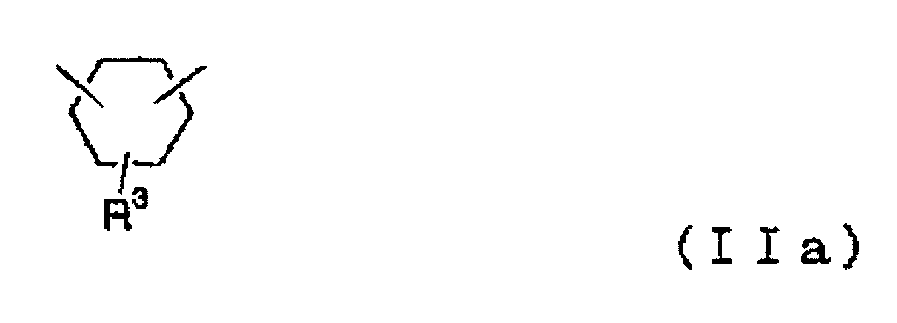
- R 1 is the following general formula (IIa) (in the formula, R 3 has 1 to 1 carbon atoms. Includes various isomers represented by 12 alkyl groups or hydrogen atoms). Specific examples thereof include 1,2-cyclohexanedimethanol, 1,3-cyclohexanedimethanol, and 1,4-cyclohexanedimethanol.
- R 1 is the following general formula (IIb) (in the formula). , N represents 0 or 1) and includes various isomers represented by).
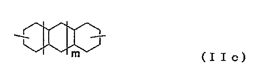
- R 1 is the following general formula (IIc) (in the formula, in the formula).
- m includes various isomers represented by 0 or 1). Specific examples thereof include 2,6-decalin dimethanol, 1,5-decalin dimethanol, and 2,3-decalin dimethanol.
- norbornane dimethanol which is an alicyclic dihydroxy compound represented by the above general formula (II)
- various isomers in which R 1 is represented by the following general formula (IId) in the general formula (II) are used. Include. Specific examples of such a substance include 2,3-norbornane dimethanol, 2,5-norbornane dimethanol and the like.
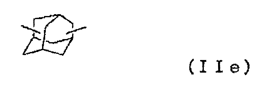
- the adamantane dimethanol which is an alicyclic dihydroxy compound represented by the general formula (II), includes various isomers in which R 1 is represented by the following general formula (IIe) in the general formula (II). Specific examples of such a substance include 1,3-adamantane dimethanol and the like.
- R 2 is the following general formula (IIIa) (in the formula, R 3 has 1 to 1 carbon atoms. Includes various isomers represented by 12 alkyl groups or hydrogen atoms. Specific examples of such a product include 1,2-cyclohexanediol, 1,3-cyclohexanediol, 1,4-cyclohexanediol, 2-methyl-1,4-cyclohexanediol and the like.
- R 2 is the following general formula (IIIb) (in the formula, n). Indicates 0 or 1) and includes various isomers represented by).
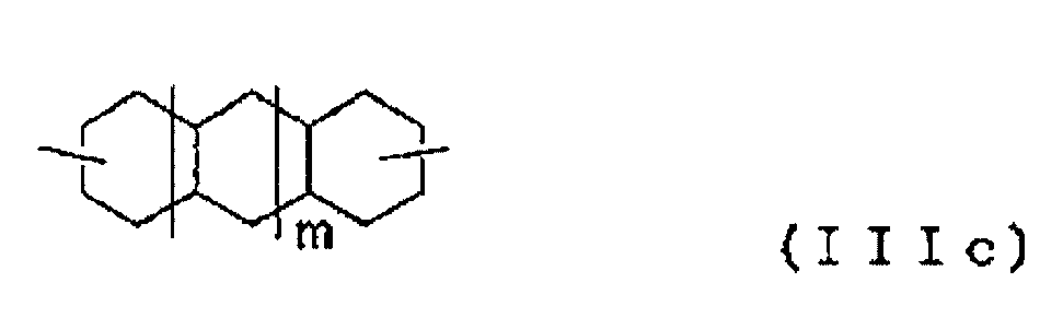
- R 2 is the following general formula (IIIc) (in the formula, m is 0, Or, it includes various isomers represented by 1). Specifically, 2,6-decalin diol, 1,5-decalin diol, 2,3-decalin diol and the like are used as such.
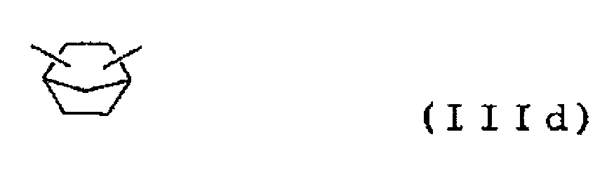
- the norbornane diol which is an alicyclic dihydroxy compound represented by the general formula (III), in the general formula (III), includes various isomers where R 2 is represented by the following general formula (IIId). Specifically, 2,3-norbornanediol, 2,5-norbornanediol and the like are used as such.
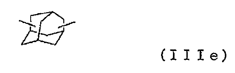
- the adamantane diol which is an alicyclic dihydroxy compound represented by the general formula (III), in the general formula (III), includes various isomers where R 2 is represented by the following general formula (IIIe). Specifically, 1,3-adamantane diol and the like are used as such substances.
- cyclohexanedimethanol, tricyclodecanedimethanol, adamantandiol, and pentacyclopentadecanedimethanol are particularly preferable, and are easily available and easy to handle. From this point of view, 1,4-cyclohexanedimethanol, 1,3-cyclohexanedimethanol, 1,2-cyclohexanedimethanol, and tricyclodecanedimethanol are preferable.
- tricyclodecanedimethanol is preferably used as the dihydroxy compound (B).
- Examples of the aliphatic dihydroxy compound that can be used in the present invention include ethylene glycol, 1,3-propanediol, 1,2-propanediol, 1,4-butanediol, 1,3-butanediol, and 1,2-butanediol. Examples include diol, 1,5-heptanediol, and 1,6-hexanediol.
- Examples of oxyalkylene glycols that can be used in the present invention include diethylene glycol, triethylene glycol, tetraethylene glycol, and polyethylene glycol.
- diols having a cyclic ether structure examples include spiroglycols and dioxane glycols.
- the above-exemplified compound is an example of an alicyclic dihydroxy compound, an aliphatic dihydroxy compound, an oxyalkylene glycol, an aromatic dihydroxy compound, and a diol having a cyclic ether structure that can be used in the present invention. It is not limited. One or more of these compounds can be used together with the dihydroxy compound represented by the formula (4).
- the ratio of the dihydroxy compound (A), for example, the dihydroxy compound represented by the formula (4) to all the dihydroxy compounds constituting the polycarbonate resin according to the present invention is not particularly limited, but is preferably 10 mol% or more, more preferably 40 mol. % Or more, more preferably 60 mol% or more, preferably 90 mol% or less, more preferably 80 mol% or less, still more preferably 70 mol% or less. If the content ratio of the structural unit derived from other dihydroxy compounds is too large, the performance such as optical characteristics may be deteriorated.
- the dihydroxy compound (A) with respect to all the dihydroxy compounds constituting the polycarbonate for example, the dihydroxy compound represented by the formula (4) and the alicyclic dihydroxy compound
- the total ratio is not particularly limited, but is preferably 80 mol% or more, more preferably 90 mol% or more, still more preferably 95 mol% or more.
- the content ratio of the dihydroxy compound (A) for example, the structural unit derived from the dihydroxy compound represented by the formula (4) and the structural unit derived from the alicyclic dihydroxy compound in the polycarbonate resin according to the present invention.
- the number of structural units derived from the dihydroxy compound represented by the formula (4) is larger than the above range and the number of structural units derived from the alicyclic dihydroxy compound is smaller, coloring becomes easier, and conversely, the dihydroxy represented by the formula (4). If the number of structural units derived from the compound is small and the number of structural units derived from the alicyclic dihydroxy compound is large, the molecular weight tends to be difficult to increase.
- the dihydroxy compound (A) with respect to all the dihydroxy compounds constituting the polycarbonate, for example, is represented by the formula (4).
- the total ratio of the dihydroxy compound and each of these dihydroxy compounds is not particularly limited and can be selected at any ratio.
- the content ratio of the dihydroxy compound (A), for example, the structural unit derived from the dihydroxy compound represented by the formula (4) and the structural unit derived from each of these dihydroxy compounds is not particularly limited, and can be selected at an arbitrary ratio. it can.
- the method for producing a retardation film according to the embodiment of the present invention includes stretching a resin film.
- the resin film is a film formed from the polycarbonate resin described in Section C above.
- the retardation film can be made by biaxial stretching.
- the biaxial stretching may be simultaneous biaxial stretching or sequential biaxial stretching.
- the stretching ratio in the longitudinal direction is preferably more than 1.0 times and 2.0 times or less, and more preferably 1.1 times to 1.5 times.
- the draw ratio in the width direction is preferably 1.6 times to 2.2 times, more preferably 1.8 times to 2.0 times.
- the stretching temperature of the resin film is preferably Tg-30 ° C to Tg + 30 ° C, more preferably Tg-10 ° C to Tg + 25 ° C, and even more preferably Tg + 8 ° C to Tg + 20 ° C.
- Tg is the glass transition temperature of the constituent material of the film.
- the measurement method and evaluation method for each characteristic are as follows.
- (1) In-plane retardation and wavelength dispersion characteristics The retardation films obtained in Examples and Comparative Examples were cut into lengths of 4 cm and widths of 4 cm and used as measurement samples.
- the in-plane phase difference Re (550) was measured using the product name "Axoscan” manufactured by Axometrics.
- Re (450) was also measured, and Re (450) / Re (550) was calculated.
- Moisture Permeability The retardation films obtained in Examples and Comparative Examples have an area of 1 m 2 in an atmosphere of a temperature of 40 ° C.
- test piece was obtained by sticking it on one side.
- the obtained test piece was immersed in an oleic acid solution under the conditions of 65 ° C. and 90% RH for 72 hours, and after being taken out, a transparent one was marked with ⁇ , and a whitened or cracked one was marked with x.
- Heat shrinkage rate (%) [[Length before heating (mm) -Length after heating (mm)] / Length before heating (mm)] x 100 Those having a heat shrinkage rate of 0% to 0.5% were evaluated as ⁇ , and those having a heat shrinkage rate of 0.5% or more were evaluated as x.
- Example 1 Preparation of resin film Isosorbide (hereinafter sometimes abbreviated as "ISB") 81.98 parts by mass, tricyclodecanedimethanol (hereinafter sometimes abbreviated as “TCDDM”) 47.19 parts by mass, diphenyl 175.1 parts by mass of carbonate (hereinafter sometimes abbreviated as "DPC”) and 0.979 parts by mass of a 0.2% by mass aqueous solution of cesium carbonate as a catalyst were put into a reaction vessel, and the reaction was carried out in a nitrogen atmosphere.
- the heating tank temperature was heated to 150 ° C., and the raw materials were dissolved while stirring as necessary (about 15 minutes).
- the pressure was changed from normal pressure to 13.3 kPa, and the generated phenol was extracted from the reaction vessel while raising the heating tank temperature to 190 ° C. in 1 hour.
- the pressure inside the reaction vessel is set to 6.67 kPa, the heating tank temperature is raised to 230 ° C. in 15 minutes, and the generated phenol is generated. It was taken out of the reaction vessel. Since the stirring torque of the stirrer increased, the temperature was raised to 250 ° C. in 8 minutes, and the pressure in the reaction vessel was brought to 0.200 kPa or less in order to remove the generated phenol.
- phase difference Film The unstretched polycarbonate resin film was subjected to preheat treatment and simultaneous biaxial stretching using a simultaneous biaxial stretching machine to obtain a retardation film.
- the preheating temperature was 137 ° C.
- the stretching temperature was 137 ° C. (Tg + 10 ° C.)
- the stretching ratio in the longitudinal direction was 1.2 times
- the stretching ratio in the width direction was 1.9 times.
- Plane retardation Re of the obtained retardation film (550) is 135 nm
- Re (450) / Re (550) is 1.02
- the moisture permeability is 88g / m 2 ⁇ 24h
- the phase difference The change was 0.6%.
- polarizing plate As the resin base material, an amorphous isophthalic copolymerized polyethylene terephthalate film (thickness: 100 ⁇ m) having a Tg of about 75 ° C. was used, and one side of the resin base material was corona-treated. did. 100 parts by weight of PVA-based resin in which polyvinyl alcohol (degree of polymerization 4200, degree of saponification 99.2 mol%) and acetacetyl-modified PVA (manufactured by Nippon Synthetic Chemical Industry Co., Ltd., trade name "Gosefimmer”) are mixed at a ratio of 9: 1.
- a PVA aqueous solution (coating solution) was prepared by dissolving 13 parts by weight of potassium iodide in water.
- a PVA-based resin layer having a thickness of 13 ⁇ m was formed by applying the above PVA aqueous solution to the corona-treated surface of the resin base material and drying at 60 ° C. to prepare a laminate.
- the obtained laminate was uniaxially stretched 2.4 times in the longitudinal direction (longitudinal direction) in an oven at 130 ° C. (aerial auxiliary stretching treatment). Next, the laminate was immersed in an insolubilizing bath at a liquid temperature of 40 ° C.
- a cycloolefin-based film (manufactured by Nippon Zeon Co., Ltd., trade name "Zeonoa”) is bonded to the surface of the obtained polarizing element opposite to the resin base material via an ultraviolet curable adhesive as a protective layer. It was. Specifically, the curable adhesive was coated so as to have a total thickness of about 1.0 ⁇ m, and bonded using a roll machine. Then, a UV ray was irradiated from the cycloolefin film side to cure the adhesive. Next, the resin base material was peeled off to obtain a polarizing plate having a cycloolefin-based film (protective layer) / polarizer. The in-plane phase difference of the protective layer was 135 nm. The angle between the slow axis of the protective layer and the absorption axis of the polarizer was made substantially parallel.
- Example 2 A retardation film was obtained in the same manner as in Example 1 except that the stretching temperature of the resin film was Tg + 15 ° C.
- the resulting in-plane retardation Re of the retardation film (550) is 137 nm, the moisture permeability is 88g / m 2 ⁇ 24h, the phase difference change was 0.6%.
- a polarizing plate with a retardation layer was obtained in the same manner as in Example 1 except that this retardation film was used and a general-purpose polycarbonate resin film was used as the protective layer.
- the in-plane phase difference of the protective layer was 135 nm.
- the obtained polarizing plate with a retardation layer was subjected to the evaluations (4) to (6) above. The results are shown in Table 1.
- Example 3 A retardation film was obtained in the same manner as in Example 1 except that the stretching temperature of the resin film was Tg + 20 ° C.
- the resulting in-plane retardation Re of the retardation film (550) is 134 nm, the moisture permeability is 86g / m 2 ⁇ 24h, the phase difference change was 0.6%.
- a layered polarizing plate was obtained.
- the in-plane phase difference of the protective layer was 0.3 nm.
- the obtained polarizing plate with a retardation layer was subjected to the evaluations (4) to (6) above. The results are shown in Table 1.
- Example 1 A cycloolefin-based resin film (manufactured by Nippon Zeon Co., Ltd., trade name "Zeonoa”) was used as the resin film, and a retardation layer film was obtained in the same manner as in Example 1 except that the stretching temperature was Tg + 20 ° C. Plane retardation Re of the obtained retardation film (550) is 135 nm, Re (450) / Re (550) is 1.01, the moisture permeability is 18g / m 2 ⁇ 24h, the phase difference The change was 0.2%. Using this retardation layer, a polarizing plate with a retardation layer was obtained in the same manner as in Example 1. The obtained polarizing plate with a retardation layer was subjected to the evaluations (4) to (6) above. The results are shown in Table 1.
- Example 3 A cycloolefin-based resin film (manufactured by Nippon Zeon Corporation, trade name "Zeonoa”) was used as the resin film, and a retardation film was obtained in the same manner as in Example 1 except that the stretching temperature was Tg + 20 ° C. Plane retardation Re of the obtained retardation film (550) is 136 nm, Re (450) / Re (550) is 1.01, the moisture permeability is 20g / m 2 ⁇ 24h, the phase difference The change was 0.2%.
- Example 2 Phase difference in the same manner as in Example 1 except that this retardation film was used and an acrylic resin film (manufactured by Mitsubishi Rayon, trade name: Acrypet VH, Tg: 113 ° C.) was used as the protective layer. A layered polarizing plate was obtained. The in-plane phase difference of the protective layer was 0.3 nm. The obtained polarizing plate with a retardation layer was subjected to the evaluations (4) to (6) above. The results are shown in Table 1.
- the rubbing treatment was performed by adjusting the rotation axis of the rubbing roller to be 45 ° counterclockwise with respect to the longitudinal direction of the triacetyl cellulose (TAC) film (manufactured by Fuji Film Co., Ltd.).
- TAC triacetyl cellulose
- the rubbing-treated TAC film was coated with a liquid crystal to obtain a liquid crystal-coated triacetyl cellulose (TAC) film.
- a retardation film was obtained in the same manner as in Example 1 except that the liquid crystal coating TAC was used for the resin film and no stretching was performed.
- Plane retardation Re of the obtained retardation film (550) is 0.1 nm, Re (450) / Re (550) is 1.09, the moisture permeability is 320g / m 2 ⁇ 24h, The phase difference change was 2.1%.
- a polarizing plate with a retardation layer was obtained in the same manner as in Example 1.
- the obtained polarizing plate with a retardation layer was subjected to the evaluations (4) to (6) above. The results are shown in Table 1.
- a retardation layer film was obtained in the same manner as in Example 1 except that the liquid crystal coating TAC was used as the resin film and no stretching was performed. Plane retardation Re of the obtained retardation film (550) is 0.1 nm, Re (450) / Re (550) is 1.09, the moisture permeability is 337g / m 2 ⁇ 24h, The phase difference change was 1.8%. Phase difference in the same manner as in Example 1 except that this retardation film was used and an acrylic resin film (manufactured by Mitsubishi Rayon, trade name: Acrypet VH, Tg: 113 ° C.) was used as the protective layer. A layered polarizing plate was obtained. The in-plane phase difference of the protective layer was 0.6 nm. The obtained polarizing plate with a retardation layer was subjected to the evaluations (4) to (6) above. The results are shown in Table 1.
- Example 6 A retardation film was obtained in the same manner as in Example 1 except that the stretching temperature of the resin film was Tg + 7 ° C. Plane retardation Re of the obtained retardation film (550) is 200 nm, the moisture permeability is 88g / m 2 ⁇ 24h, the phase difference change was 0.8%. Using this retardation layer, a polarizing plate with a retardation layer was obtained in the same manner as in Example 1. The obtained polarizing plate with a retardation layer was subjected to the evaluations (4) to (6) above. The results are shown in Table 1.
- the retardation film of the embodiment of the present invention is excellent in all of the moisture permeability, the retardation change, the deformability test, the sebum resistance test and the dimensional stability test.
- a polarizing plate with a retardation layer has a retardation layer and a polarizing plate having a polarizer and a protective layer in this order, and the retardation layer contains a specific polycarbonate resin, and a specific stretching method and a specific stretching method and It is presumed that this is achieved by stretching under stretching conditions.
- the polarizing plate with a retardation layer according to the embodiment of the present invention is suitably used for an image display device.
- Polarizing filter 11 Polarizer 12 First protective layer 13 Second protective layer 20 Phase difference layer 100 Polarizing plate with retardation layer
Landscapes
- Physics & Mathematics (AREA)
- Chemical & Material Sciences (AREA)
- Optics & Photonics (AREA)
- General Physics & Mathematics (AREA)
- Medicinal Chemistry (AREA)
- Organic Chemistry (AREA)
- Polymers & Plastics (AREA)
- Health & Medical Sciences (AREA)
- Chemical Kinetics & Catalysis (AREA)
- Polarising Elements (AREA)
- Liquid Crystal (AREA)
- Polyesters Or Polycarbonates (AREA)
- Devices For Indicating Variable Information By Combining Individual Elements (AREA)
Abstract
Description
1つの実施形態においては、上記ポリカーボネート系樹脂は、下記式(4)で表されるジヒドロキシ化合物に由来する構造単位を含む。

HOCH2-R1-CH2OH (II)

1つの実施形態においては、上記位相差層付偏光板は、耐皮脂性試験において白化およびクラックが抑制されている。
1つの実施形態においては、上記位相差層付偏光板は、寸法安定性試験において寸法変化が抑制されている。
1つの実施形態においては、上記位相差層の透湿度は100g/m2・24h以下である。
1つの実施形態においては、温度65℃かつ湿度90%の条件下において500時間保存した後の位相差層の位相差変化は1.5%以下である。
1つの実施形態においては、上記位相差層付偏光板は、長尺状であり、上記位相差層は、長尺方向に対して40°~50°の角度をなす方向に遅相軸を有する斜め延伸フィルムである。
本明細書における用語および記号の定義は下記の通りである。
(1)屈折率(nx、ny、nz)
「nx」は面内の屈折率が最大になる方向(すなわち、遅相軸方向)の屈折率であり、「ny」は面内で遅相軸と直交する方向(すなわち、進相軸方向)の屈折率であり、「nz」は厚み方向の屈折率である。
(2)面内位相差(Re)
「Re(λ)」は、23℃における波長λnmの光で測定した面内位相差である。例えば、「Re(550)」は、23℃における波長550nmの光で測定した面内位相差である。Re(λ)は、層(フィルム)の厚みをd(nm)としたとき、式:Re(λ)=(nx-ny)×dによって求められる。
(3)厚み方向の位相差(Rth)
「Rth(λ)」は、23℃における波長λnmの光で測定した厚み方向の位相差である。例えば、「Rth(550)」は、23℃における波長550nmの光で測定した厚み方向の位相差である。Rth(λ)は、層(フィルム)の厚みをd(nm)としたとき、式:Rth(λ)=(nx-nz)×dによって求められる。
(4)Nz係数
Nz係数は、Nz=Rth/Reによって求められる。
(5)角度
本明細書において角度に言及するときは、当該角度は基準方向に対して時計回りおよび反時計回りの両方を包含する。したがって、例えば「45°」は±45°を意味する。
図1は、本発明の1つの実施形態による位相差層付偏光板の概略断面図である。位相差層付偏光板は、画像表示装置の視認側に用いられる。本実施形態の位相差層付偏光板100は、視認側から順に位相差層20と偏光板10とを有する。偏光板10は、偏光子11と、偏光子11の一方の側に配置された第1の保護層12と、偏光子11のもう一方の側に配置された第2の保護層13とを含む。目的に応じて、第1の保護層12および第2の保護層13の一方は省略されてもよい。偏光子11の吸収軸と位相差層20の遅相軸とのなす角度は、例えば40°~50°であり、好ましくは42°~48°であり、より好ましくは44°~46°である。位相差層付偏光板は、必要に応じて、位相差層20の視認側にハードコート層(図示せず)を有していてもよい。
B-1.偏光子
偏光子としては、任意の適切な偏光子が採用され得る。例えば、偏光子を形成する樹脂フィルムは、単層の樹脂フィルムであってもよく、二層以上の積層体であってもよい。
保護層は、偏光子を保護するフィルムとして使用できる任意の適切な保護フィルムで形成される。保護フィルムの主成分となる材料の具体例としては、トリアセチルセルロース(TAC)等のセルロース系樹脂や、ポリエステル系、ポリビニルアルコール系、ポリカーボネート系、ポリアミド系、ポリイミド系、ポリエーテルスルホン系、ポリスルホン系、ポリスチレン系、ポリノルボルネン系、ポリオレフィン系、(メタ)アクリル系、アセテート系等の透明樹脂等が挙げられる。また、(メタ)アクリル系、ウレタン系、(メタ)アクリルウレタン系、エポキシ系、シリコーン系等の熱硬化型樹脂または紫外線硬化型樹脂等も挙げられる。この他にも、例えば、シロキサン系ポリマー等のガラス質系ポリマーも挙げられる。また、特開2001-343529号公報(WO01/37007)に記載のポリマーフィルムも使用できる。このフィルムの材料としては、例えば、側鎖に置換または非置換のイミド基を有する熱可塑性樹脂と、側鎖に置換または非置換のフェニル基ならびにニトリル基を有する熱可塑性樹脂を含有する樹脂組成物が使用でき、例えば、イソブテンとN-メチルマレイミドからなる交互共重合体と、アクリロニトリル・スチレン共重合体とを有する樹脂組成物が挙げられる。当該ポリマーフィルムは、例えば、上記樹脂組成物の押出成形物であり得る。
本発明の実施形態による位相差層は、位相差フィルムで形成される。本発明の実施形態による位相差フィルムは、ポリカーボネート樹脂を含む。本発明の実施形態による位相差フィルムは、代表的には、ポリカーボネート樹脂フィルムの延伸フィルムである。
位相差フィルムは、上記のとおり、代表的には、ポリカーボネート樹脂フィルムの延伸フィルムである。
本発明に係るポリカーボネート樹脂は、下記構造式(1)で表される結合構造を有するジヒドロキシ化合物に由来する構成単位を少なくとも含むものであり、分子内に少なくとも一つの結合構造 -CH2-O- を有するジヒドロキシ化合物を少なくとも含むジヒドロキシ化合物と、炭酸ジエステルとを、重合触媒の存在下反応させることにより製造される。
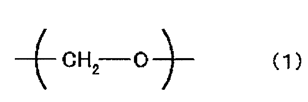
ジヒドロキシ化合物(A)における「連結基-CH2-O-」とは、水素原子以外の原子と互いに結合して分子を構成する構造を意味する。この連結基において、少なくとも酸素原子が結合し得る原子又は炭素原子と酸素原子が同時に結合し得る原子としては、炭素原子が最も好ましい。ジヒドロキシ化合物(A)中の「連結基-CH2-O-」の数は、好ましくは1以上、より好ましくは2~4である。
ル)フルオレンで例示されるような、側鎖に芳香族基を有し、主鎖に芳香族基に結合したエーテル基を有する化合物、ビス[4-(2-ヒドロキシエトキシ)フェニル]メタン、ビス[4-(2-ヒドロキシエトキシ)フェニル]ジフェニルメタン、1,1-ビス[4-(2-ヒドロキシエトキシ)フェニル]エタン、1,1-ビス[4-(2-ヒドロキシエトキシ)フェニル]-1-フェニルエタン、2,2-ビス[4-(2-ヒドロキシエトキシ)フェニル]プロパン、2,2-ビス[4-(2-ヒドロキシエトキシ)-3-メチルフェニル]プロパン、2,2-ビス[3,5-ジメチル-4-(2-ヒドロキシエトキシ)フェニル]プロパン、1,1-ビス[4-(2-ヒドロキシエトキシ)フェニル]-3,3,5-トリメチルシクロヘキサン、1,1-ビス[4-(2-ヒドロキシエトキシ)フェニル]シクロヘキサン、1,4-ビス[4-(2-ヒドロキシエトキシ)フェニル]シクロヘキサン、1,3-ビス[4-(2-ヒドロキシエトキシ)フェニル]シクロヘキサン、2,2-ビス[4-(2-ヒドロキシエトキシ)-3-フェニルフェニル]プロパン、2,2-ビス[(2-ヒドロキシエトキシ)-3-イソプロピルフェニル]プロパン、2,2-ビス[3-tert-ブチル-4-(2-ヒドロキシエトキシ)フェニル]プロパン、2,2-ビス[4-(2-ヒドロキシエトキシ)フェニル]ブタン、2,2-ビス[4-(2-ヒドロキシエトキシ)フェニル]-4-メチルペンタン、2,2-ビス[4-(2-ヒドロキシエトキシ)フェニル]オクタン、1,1-ビス[4-(2-ヒドロキシエトキシ)フェニル]デカン、2,2-ビス[3-ブロモ-4-(2-ヒドロキシエトキシ)フェニル]プロパン、2,2-ビス[3-シクロヘキシル-4-(2-ヒドロキシエトキシ)フェニル]プロパンで例示されるような、ビス(ヒドロキシアルコキシアリール)アルカン類、1,1-ビス[4-(2-ヒドロキシエトキシ)フェニル]シクロヘキサン、1,1-ビス[3-シクロヘキシル-4-(2-ヒドロキシエトキシ)フェニル]シクロヘキサン、1,1-ビス[4-(2-ヒドロキシエトキシ)フェニル]シクロペンタンで例示されるような、ビス(ヒドロキシアルコキシアリール)シクロアルカン類、4,4’-ビス(2-ヒドロキシエトキシ)ジフェニルエ-テル、4,4’-ビス(2-ヒドロキシエトキシ)-3,3’-ジメチルジフェニルエ-テルで例示されるような、ジヒドロキシアルコキシジアリールエーテル類、4,4’-ビス(2-ヒドロキエトキシフェニル)スルフィド、4,4’-ビス[4-(2-ジヒドロキシエトキシ)-3-メチルフェニル]スルフィドで例示されるような、ビスヒドロキシアルコキシアリールスルフィド類、4,4’-ビス(2-ヒドロキエトキシフェニル)スルホキシド、4,4’-ビス[4-(2-ジヒドロキシエトキシ)-3-メチルフェニル]スルホキシドで例示されるような、ビスヒドロキシアルコキシアリールスルホキシド類、4,4’-ビス(2-ヒドロキエトキシフェニル)スルホン、4,4’-ビス[4-(2-ジヒドロキシエトキシ)-3-メチルフェニル]スルホンで例示されるような、ビスヒドロキシアルコキシアリールスルホン類、1,4-ビスヒドロキシエトキシベンゼン、1,3-ビスヒドロキシエトキシベンゼン、1,2-ビスヒドロキシエトキシベンゼン、1,3-ビス[2-[4-(2-ヒドロキシエトキシ)フェニル]プロピル]ベンゼン、1,4-ビス[2-[4-(2-ヒドロキシエトキシ)フェニル]プロピル]ベンゼン、4,4’-ビス(2-ヒドロキシエトキシ)ビフェニル、1,3-ビス[4-(2-ヒドロキシエトキシ)フェニル]-5,7-ジメチルアダマンタン、下記式(4)で表されるジヒドロキシ化合物に代表される無水糖アルコール、および下記一般式(6)で表されるスピログリコール等の環状エーテル構造を有する化合物が挙げられ、これらは単独で用いてもよく、2種以上を組み合わせて用いてもよい。
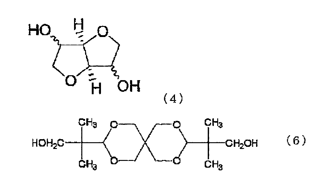
本発明においては、ジヒドロキシ化合物としてジヒドロキシ化合物(A)以外のジヒドロキシ化合物である、ジヒドロキシ化合物(B)を用いてもよい。ジヒドロキシ化合物(B)としては、例えば、脂環式ジヒドロキシ化合物、脂肪族ジヒドロキシ化合物、オキシアルキレングリコール類、芳香族ジヒドロキシ化合物、環状エーテル構造を有するジオール類を、ポリカーボネートの構成単位となるジヒドロキシ化合物として、ジヒドロキシ化合物(A)、例えば式(4)で表されるジヒドロキシ化合物とともに用いることができる。
HOCH2-R1-CH2OH (II)
HO-R2-OH (III)
(式(II)、(III)中、R1、R2はそれぞれ、炭素数4~20のシクロアルキレン基を示す。)
上記一般式(II)で表される脂環式ジヒドロキシ化合物であるシクロヘキサンジメタノールとしては、一般式(II)において、R1が下記一般式(IIa)(式中、R3は炭素数1~12のアルキル基又は水素原子を示す。)で表される種々の異性体を包含する。このようなものとしては、具体的には、1,2-シクロヘキサンジメタノール、1,3-シクロヘキサンジメタノール、1,4-シクロヘキサンジメタノールなどが挙げられる。




本発明の実施形態による位相差フィルムの製造方法は、樹脂フィルムを延伸処理することを含む。樹脂フィルムは、上記C項で説明したポリカーボネート樹脂から形成されたフィルムである。
(1)面内位相差および波長分散特性
実施例および比較例で得られた位相差フィルムを長さ4cmおよび幅4cmに切り出し、測定試料とした。当該測定試料について、Axometrics社製、製品名「Axoscan」を用いて面内位相差Re(550)を測定した。さらに、Re(450)も測定し、Re(450)/Re(550)を算出した。
(2)透湿度
実施例および比較例で得られた位相差フィルムについて、JIS Z 0208の透湿度試験(カップ法)に準拠して、温度40℃、湿度92%RHの雰囲気中、面積1m2の試料を24時間に通過する水蒸気量(g)を測定した。
(3)位相差変化
実施例および比較例で得られた位相差フィルムを、5cm×5cmに切りだし、片方の面に粘着剤をハンドローラーで貼り付け、粘着剤面をアルカリガラスの片面に貼り付けて試験片を得た。試験片を温度65℃かつ湿度90%のオーブンに500時間保存(加湿試験)し、試験開始前および試験後の位相差変化(%)を算出した。
(4)異形加工性試験
実施例および比較例で得られた位相差層付偏光板にCO2レーザーを3Kwのエネルギーで照射し、フィルムの流れ方向および流れ方向と垂直の方向にカットし、200mm×200mmの測定試料を得た。レーザー顕微鏡を用いてカットされた部分を観察し、クラックが入っていなければ〇、クラックが入るおよび/またはカットができない場合は×とした。
(5)耐皮脂性試験
実施例および比較例で得られた位相差層付偏光板を5cm×5cmに切りだし、片方の面に粘着剤をハンドローラーで貼り付け、粘着剤面をアルカリガラスの片面に貼り付けて試験片を得た。得られた試験片を、オレイン酸溶液に、65℃、90%RHの条件下72時間浸漬させ、取り出した後に透明なものを〇、白化またはクラックが入っているものを×とした。
(6)寸法収縮率
実施例および比較例で得られた位相差層付偏光板を、幅100mm、長さ100mmに切り取り(試験片)、4隅部にクロスでキズを付けクロスキズの中央部4点の長手方向(MD方向)と幅方向(TD方向)の加熱前の長さ(mm)をCNC三次元測定機(株式会社ミツトヨ社製 LEGEX774)により測定した。その後、オーブンに投入し、加熱処理(温度65℃、湿度90%)を行った。室温で1時間放冷後に再度、4隅部4点のMD方向とTD方向の加熱後の長さ(mm)をCNC三次元測定機により測定し、その測定値を下記式に代入することにより、MD方向とTD方向のそれぞれの熱収縮率を求めた。
熱収縮率(%)=[[加熱前の長さ(mm)-加熱後の長さ(mm)]/加熱前の長さ(mm)]×100
熱収縮率が0%~0.5%のものを〇、0.5%以上のものを×とした。
1.樹脂フィルムの作製
イソソルビド(以下「ISB」と略記することがある)81.98質量部に対して、トリシクロデカンジメタノール(以下「TCDDM」と略記することがある)47.19質量部、ジフェニルカーボネート(以下「DPC」と略記することがある)175.1質量部、及び触媒として、炭酸セシウム0.2質量%水溶液0.979質量部を反応容器に投入し、窒素雰囲気下にて、反応の第1段目の工程として、加熱槽温度を150℃に加熱し、必要に応じて攪拌しながら、原料を溶解させた(約15分)。次いで、圧力を常圧から13.3kPaにし、加熱槽温度を190℃まで1時間で上昇させながら、発生するフェノールを反応容器外へ抜き出した。反応容器全体を190℃で15分保持した後、第2段目の工程として、反応容器内の圧力を6.67kPaとし、加熱槽温度を230℃まで、15分で上昇させ、発生するフェノールを反応容器外へ抜き出した。攪拌機の攪拌トルクが上昇してくるので、8分で250℃まで昇温し、さらに発生するフェノールを取り除くため、反応容器内の圧力を0.200kPa以下に到達させた。所定の攪拌トルクに到達後、反応を終了し、生成した反応物を水中に押し出して、ポリカーボネート樹脂のペレットを得た。得られたポリカーボネート樹脂を80℃で5時間真空乾燥をした後、単軸押出機(東芝機械社製、シリンダー設定温度:250℃)、Tダイ(幅300mm、設定温度:250℃)、チルロール(設定温度:120~130℃)および巻取機を備えたフィルム製膜装置を用いて、厚み60μmのポリカーボネート樹脂フィルムを作製した。
未延伸の上記ポリカーボネート樹脂フィルムを、同時二軸延伸機を用い、予熱処理および同時二軸延伸に供し、位相差フィルムを得た。予熱温度は137℃とした。延伸温度は137℃(Tg+10℃)とし、長手方向の延伸倍率を1.2倍、幅方向の延伸倍率を1.9倍とした。得られた位相差フィルムの面内位相差Re(550)は135nmであり、Re(450)/Re(550)は1.02であり、透湿度は88g/m2・24hであり、位相差変化は0.6%であった。
樹脂基材として、長尺状で、Tg約75℃である、非晶質のイソフタル共重合ポリエチレンテレフタレートフィルム(厚み:100μm)を用い、樹脂基材の片面に、コロナ処理を施した。
ポリビニルアルコール(重合度4200、ケン化度99.2モル%)およびアセトアセチル変性PVA(日本合成化学工業社製、商品名「ゴーセファイマー」)を9:1で混合したPVA系樹脂100重量部に、ヨウ化カリウム13重量部を添加したものを水に溶かし、PVA水溶液(塗布液)を調製した。
樹脂基材のコロナ処理面に、上記PVA水溶液を塗布して60℃で乾燥することにより、厚み13μmのPVA系樹脂層を形成し、積層体を作製した。
得られた積層体を、130℃のオーブン内で縦方向(長手方向)に2.4倍に一軸延伸した(空中補助延伸処理)。
次いで、積層体を、液温40℃の不溶化浴(水100重量部に対して、ホウ酸を4重量部配合して得られたホウ酸水溶液)に30秒間浸漬させた(不溶化処理)。
次いで、液温30℃の染色浴(水100重量部に対して、ヨウ素とヨウ化カリウムを1:7の重量比で配合して得られたヨウ素水溶液)に、最終的に得られる偏光子の単体透過率(Ts)が所望の値となるように濃度を調整しながら60秒間浸漬させた(染色処理)。
次いで、液温40℃の架橋浴(水100重量部に対して、ヨウ化カリウムを3重量部配合し、ホウ酸を5重量部配合して得られたホウ酸水溶液)に30秒間浸漬させた(架橋処理)。
その後、積層体を、液温70℃のホウ酸水溶液(ホウ酸濃度4重量%、ヨウ化カリウム濃度5重量%)に浸漬させながら、周速の異なるロール間で縦方向(長手方向)に総延伸倍率が5.5倍となるように一軸延伸を行った(水中延伸処理)。
その後、積層体を液温20℃の洗浄浴(水100重量部に対して、ヨウ化カリウムを4重量部配合して得られた水溶液)に浸漬させた(洗浄処理)。
その後、約90℃に保たれたオーブン中で乾燥しながら、表面温度が約75℃に保たれたSUS製の加熱ロールに接触させた(乾燥収縮処理)。
このようにして、樹脂基材上に厚み約5μmの偏光子を形成し、樹脂基材/偏光子の構成を有する偏光板を得た。
さらに、得られた偏光子の樹脂基材と反対側の面に、保護層として、シクロオレフィン系フィルム(日本ゼオン社製、商品名「ゼオノア」)を、紫外線硬化型接着剤を介して貼り合せた。具体的には、硬化型接着剤の総厚みが約1.0μmになるように塗工し、ロール機を使用して貼り合わせた。その後、UV光線をシクロオレフィン系フィルム側から照射して接着剤を硬化させた。次いで、樹脂基材を剥離してシクロオレフィン系フィルム(保護層)/偏光子の構成を有する偏光板を得た。該保護層の面内位相差は135nmであった。保護層の遅相軸と偏光子の吸収軸とのなす角度は、実質的に平行とした。
上記偏光板の偏光子側に、上記位相差層フィルムを貼り合わせた。偏光子の吸収軸と位相差フィルムの遅相軸とのなす角度は45°とした。さらに、位相差フィルムの偏光子と反対側に、ハードコート層を形成して、位相差層付偏光板を得た。得られた位相差層付偏光板を、上記(4)~(6)の評価に供した。結果を表1に示す。
樹脂フィルムの延伸温度をTg+15℃としたこと以外は実施例1と同様にして位相差フィルムを得た。得られた位相差フィルムの面内位相差Re(550)は137nmであり、透湿度は88g/m2・24hであり、位相差変化は0.6%であった。この位相差フィルムを用いたこと、および保護層に汎用ポリカーボネート樹脂フィルムを用いたこと以外は実施例1と同様にして位相差層付偏光板を得た。保護層の面内位相差は135nmであった。得られた位相差層付偏光板を、上記(4)~(6)の評価に供した。結果を表1に示す。
樹脂フィルムの延伸温度をTg+20℃としたこと以外は実施例1と同様にして位相差フィルムを得た。得られた位相差フィルムの面内位相差Re(550)は134nmであり、透湿度は86g/m2・24hであり、位相差変化は0.6%であった。この位相差フィルムを用いたこと、および保護層にアクリル系樹脂フィルム(三菱レイヨン社製、商品名 : アクリペットVH、Tg : 113℃)を用いたこと以外は実施例1と同様にして位相差層付偏光板を得た。保護層の面内位相差は0.3nmであった。得られた位相差層付偏光板を、上記(4)~(6)の評価に供した。結果を表1に示す。
樹脂フィルムにシクロオレフィン系樹脂フィルム(日本ゼオン社製、商品名「ゼオノア」)を用い、延伸温度をTg+20℃としたこと以外は実施例1と同様にして位相差層フィルムを得た。得られた位相差フィルムの面内位相差Re(550)は135nmであり、Re(450)/Re(550)は1.01であり、透湿度は18g/m2・24hであり、位相差変化は0.2%であった。この位相差層を用いて、実施例1と同様にして位相差層付偏光板を得た。得られた位相差層付偏光板を、上記(4)~(6)の評価に供した。結果を表1に示す。
樹脂フィルムにシクロオレフィン系樹脂フィルム(日本ゼオン社製、商品名「ゼオノア」)を用い、延伸温度をTg+20℃としたこと以外は実施例1と同様にして位相差フィルムを得た。得られた位相差フィルムの面内位相差Re(550)は135nmであり、Re(450)/Re(550)は1.01であり、透湿度は18g/m2・24hであり、位相差変化は0.2%であった。この位相差フィルムを用いたこと、および保護層に汎用ポリカーボネート樹脂フィルムを用いたこと以外は実施例1と同様にして位相差層付偏光板を得た。保護層の面内位相差は135nmであった。得られた位相差層付偏光板を、上記(4)~(6)の評価に供した。結果を表1に示す。
樹脂フィルムにシクロオレフィン系樹脂フィルム(日本ゼオン社製、商品名「ゼオノア」)を用い、延伸温度をTg+20℃としたこと以外は実施例1と同様にして位相差フィルムを得た。得られた位相差フィルムの面内位相差Re(550)は136nmであり、Re(450)/Re(550)は1.01であり、透湿度は20g/m2・24hであり、位相差変化は0.2%であった。この位相差フィルムを用いたこと、および保護層にアクリル系樹脂フィルム(三菱レイヨン社製、商品名 : アクリペットVH、Tg : 113℃)を用いたこと以外は実施例1と同様にして位相差層付偏光板を得た。保護層の面内位相差は0.3nmであった。得られた位相差層付偏光板を、上記(4)~(6)の評価に供した。結果を表1に示す。
トリアセチルセルロース(TAC)フィルム(富士フィルム社製)の長手方向に対してラビングローラーの回転軸が反時計回りに45°となるように調節し、ラビング処理を行った。ラビング処理した上記TACフィルムに液晶塗工をして、液晶塗工トリアセチルセルロース(TAC)フィルムを得た。樹脂フィルムに上記液晶塗工TACを用いたこと、および延伸を行わなかったこと以外は実施例1と同様にして、位相差フィルムを得た。得られた位相差フィルムの面内位相差Re(550)は0.1nmであり、Re(450)/Re(550)は1.09であり、透湿度は320g/m2・24hであり、位相差変化は2.1%であった。この位相差層を用いて、実施例1と同様にして位相差層付偏光板を得た。得られた位相差層付偏光板を、上記(4)~(6)の評価に供した。結果を表1に示す。
樹脂フィルムに上記液晶塗工TACを用いたこと、および延伸を行わなかったこと以外は実施例1と同様にして位相差層フィルムを得た。得られた位相差フィルムの面内位相差Re(550)は0.1nmであり、Re(450)/Re(550)は1.09であり、透湿度は337g/m2・24hであり、位相差変化は1.8%であった。この位相差フィルムを用いたこと、および保護層にアクリル系樹脂フィルム(三菱レイヨン社製、商品名 : アクリペットVH、Tg : 113℃)を用いたこと以外は実施例1と同様にして位相差層付偏光板を得た。保護層の面内位相差は0.6nmであった。得られた位相差層付偏光板を、上記(4)~(6)の評価に供した。結果を表1に示す。
樹脂フィルムの延伸温度をTg+7℃としたこと以外は実施例1と同様にして位相差フィルムを得た。得られた位相差フィルムの面内位相差Re(550)は200nmであり、透湿度は88g/m2・24hであり、位相差変化は0.8%であった。この位相差層を用いて、実施例1と同様にして位相差層付偏光板を得た。得られた位相差層付偏光板を、上記(4)~(6)の評価に供した。結果を表1に示す。

11 偏光子
12 第1の保護層
13 第2の保護層
20 位相差層
100 位相差層付偏光板
Claims (9)
- 画像表示装置の視認側に配置される位相差層付偏光板であって、
視認側から位相差層と偏光子および保護層を有する偏光板とをこの順に有し、
該位相差層が、ポリカーボネート系樹脂を含み、Re(450)/Re(550)が0.98~1.03であり、Re(550)が80nm~190nmである、
位相差層付偏光板。 - 前記ポリカーボネート系樹脂が、下記式(4)で表されるジヒドロキシ化合物に由来する構造単位を含む、請求項1に記載の位相差層付偏光板。

- 前記ポリカーボネート系樹脂が、脂環式ジヒドロキシ化合物に由来する構造単位をさらに含み、
該脂環式ジヒドロキシ化合物が、下記一般式(II)で表され、R1が下記(IIb)で表される構造であり、n=0である、
請求項2に記載の位相差層付偏光板。
HOCH2-R1-CH2OH (II)

- 異形加工性試験においてクラックが抑制されている、請求項1から3のいずれかに記載の位相差層付偏光板。
- 耐皮脂性試験において白化およびクラックが抑制されている、請求項1から4のいずれかに記載の位相差層付偏光板。
- 寸法安定性試験において寸法変化が抑制されている、請求項1から5のいずれかに記載の位相差層付偏光板。
- 前記位相差層の透湿度が100g/m2・24h以下である、請求項1から6のいずれかに記載の位相差層付偏光板。
- 温度65℃かつ湿度90%の条件下において500時間保存した後の前記位相差層の位相差変化が1.5%以下である、請求項1から7のいずれかに記載の位相差層付偏光板。
- 長尺状であり、前記位相差層が、長尺方向に対して40°~50°の角度をなす方向に遅相軸を有する斜め延伸フィルムである、請求項1から8のいずれかに記載の位相差層付偏光板。
Priority Applications (4)
| Application Number | Priority Date | Filing Date | Title |
|---|---|---|---|
| CN202080024427.9A CN113631972B (zh) | 2019-03-27 | 2020-03-18 | 带相位差层的偏光板 |
| JP2021509250A JP7543250B2 (ja) | 2019-03-27 | 2020-03-18 | 位相差層付偏光板 |
| KR1020217024803A KR20210144668A (ko) | 2019-03-27 | 2020-03-18 | 위상차층 부착 편광판 |
| JP2023174057A JP2023184529A (ja) | 2019-03-27 | 2023-10-06 | 位相差層付偏光板 |
Applications Claiming Priority (2)
| Application Number | Priority Date | Filing Date | Title |
|---|---|---|---|
| JP2019-060694 | 2019-03-27 | ||
| JP2019060694 | 2019-03-27 |
Publications (1)
| Publication Number | Publication Date |
|---|---|
| WO2020196146A1 true WO2020196146A1 (ja) | 2020-10-01 |
Family
ID=72610181
Family Applications (1)
| Application Number | Title | Priority Date | Filing Date |
|---|---|---|---|
| PCT/JP2020/011927 Ceased WO2020196146A1 (ja) | 2019-03-27 | 2020-03-18 | 位相差層付偏光板 |
Country Status (4)
| Country | Link |
|---|---|
| JP (2) | JP7543250B2 (ja) |
| KR (1) | KR20210144668A (ja) |
| CN (1) | CN113631972B (ja) |
| WO (1) | WO2020196146A1 (ja) |
Cited By (2)
| Publication number | Priority date | Publication date | Assignee | Title |
|---|---|---|---|---|
| WO2025177938A1 (ja) * | 2024-02-22 | 2025-08-28 | 日東電工株式会社 | 光学積層体の製造方法 |
| WO2025177937A1 (ja) * | 2024-02-22 | 2025-08-28 | 日東電工株式会社 | 光学積層体および表示システム |
Citations (7)
| Publication number | Priority date | Publication date | Assignee | Title |
|---|---|---|---|---|
| JP2009282424A (ja) * | 2008-05-26 | 2009-12-03 | Epson Imaging Devices Corp | 液晶表示装置、電子機器、及び偏光体 |
| JP2012031370A (ja) * | 2009-11-19 | 2012-02-16 | Mitsubishi Chemicals Corp | ポリカーボネート樹脂フィルム並びに透明フィルム及びその製造方法 |
| WO2016136509A1 (ja) * | 2015-02-26 | 2016-09-01 | 日東電工株式会社 | 位相差層付偏光板および画像表示装置 |
| JP2017049574A (ja) * | 2015-09-01 | 2017-03-09 | 日東電工株式会社 | 光学積層体 |
| WO2017098970A1 (ja) * | 2015-12-10 | 2017-06-15 | 日東電工株式会社 | 円偏光板およびそれを用いたフレキシブルな画像表示装置 |
| JP2018012182A (ja) * | 2016-07-22 | 2018-01-25 | 日東電工株式会社 | 偏光板の製造方法およびその製造装置 |
| WO2018180729A1 (ja) * | 2017-03-30 | 2018-10-04 | 日本ゼオン株式会社 | 有機エレクトロルミネッセンス表示装置用の複層フィルム、並びに、これを含む偏光板、反射防止フィルム及び有機エレクトロルミネッセンス表示装置 |
Family Cites Families (13)
| Publication number | Priority date | Publication date | Assignee | Title |
|---|---|---|---|---|
| JPH1010523A (ja) | 1996-06-24 | 1998-01-16 | Dainippon Printing Co Ltd | 液晶表示装置 |
| JP4281998B2 (ja) * | 2003-06-06 | 2009-06-17 | 三菱瓦斯化学株式会社 | ポリカーボネート樹脂組成物 |
| KR101501783B1 (ko) * | 2006-08-18 | 2015-03-11 | 미츠비시 가스 가가쿠 가부시키가이샤 | 폴리카보네이트 수지 및 이것을 사용한 광학필름 |
| JP2014182274A (ja) * | 2013-03-19 | 2014-09-29 | Fujifilm Corp | 偏光板、液晶表示装置、および液晶表示装置の製造方法。 |
| JP6398242B2 (ja) * | 2013-03-21 | 2018-10-03 | 三菱ケミカル株式会社 | 樹脂組成物及びそれを用いたフィルム |
| JP2015191163A (ja) * | 2014-03-28 | 2015-11-02 | 三菱化学株式会社 | 画像表示装置用前面保護パネル |
| JP6189355B2 (ja) * | 2014-04-16 | 2017-08-30 | 三菱ケミカル株式会社 | 位相差フィルム、円偏光板及び画像表示装置 |
| JP6565597B2 (ja) | 2014-10-28 | 2019-08-28 | 三菱ケミカル株式会社 | ポリカーボネート樹脂、成形品及び光学フィルム |
| CN119119704A (zh) * | 2015-04-21 | 2024-12-13 | 三菱化学株式会社 | 聚碳酸酯树脂薄膜 |
| JP2017040727A (ja) * | 2015-08-19 | 2017-02-23 | コニカミノルタ株式会社 | 光学フィルム及び光学フィルムの製造方法 |
| JP6565577B2 (ja) * | 2015-10-15 | 2019-08-28 | 三菱ケミカル株式会社 | ポリカーボネート樹脂、及びそれよりなる光学フィルム |
| JP6551842B2 (ja) * | 2015-10-20 | 2019-07-31 | 新日本無線株式会社 | 半導体装置 |
| JP6453746B2 (ja) * | 2015-12-02 | 2019-01-16 | 日東電工株式会社 | 長尺状の光学積層体および画像表示装置 |
-
2020
- 2020-03-18 CN CN202080024427.9A patent/CN113631972B/zh active Active
- 2020-03-18 KR KR1020217024803A patent/KR20210144668A/ko not_active Ceased
- 2020-03-18 JP JP2021509250A patent/JP7543250B2/ja active Active
- 2020-03-18 WO PCT/JP2020/011927 patent/WO2020196146A1/ja not_active Ceased
-
2023
- 2023-10-06 JP JP2023174057A patent/JP2023184529A/ja not_active Withdrawn
Patent Citations (7)
| Publication number | Priority date | Publication date | Assignee | Title |
|---|---|---|---|---|
| JP2009282424A (ja) * | 2008-05-26 | 2009-12-03 | Epson Imaging Devices Corp | 液晶表示装置、電子機器、及び偏光体 |
| JP2012031370A (ja) * | 2009-11-19 | 2012-02-16 | Mitsubishi Chemicals Corp | ポリカーボネート樹脂フィルム並びに透明フィルム及びその製造方法 |
| WO2016136509A1 (ja) * | 2015-02-26 | 2016-09-01 | 日東電工株式会社 | 位相差層付偏光板および画像表示装置 |
| JP2017049574A (ja) * | 2015-09-01 | 2017-03-09 | 日東電工株式会社 | 光学積層体 |
| WO2017098970A1 (ja) * | 2015-12-10 | 2017-06-15 | 日東電工株式会社 | 円偏光板およびそれを用いたフレキシブルな画像表示装置 |
| JP2018012182A (ja) * | 2016-07-22 | 2018-01-25 | 日東電工株式会社 | 偏光板の製造方法およびその製造装置 |
| WO2018180729A1 (ja) * | 2017-03-30 | 2018-10-04 | 日本ゼオン株式会社 | 有機エレクトロルミネッセンス表示装置用の複層フィルム、並びに、これを含む偏光板、反射防止フィルム及び有機エレクトロルミネッセンス表示装置 |
Cited By (2)
| Publication number | Priority date | Publication date | Assignee | Title |
|---|---|---|---|---|
| WO2025177938A1 (ja) * | 2024-02-22 | 2025-08-28 | 日東電工株式会社 | 光学積層体の製造方法 |
| WO2025177937A1 (ja) * | 2024-02-22 | 2025-08-28 | 日東電工株式会社 | 光学積層体および表示システム |
Also Published As
| Publication number | Publication date |
|---|---|
| KR20210144668A (ko) | 2021-11-30 |
| JP7543250B2 (ja) | 2024-09-02 |
| JP2023184529A (ja) | 2023-12-28 |
| JPWO2020196146A1 (ja) | 2021-12-09 |
| CN113631972B (zh) | 2025-01-03 |
| TW202101040A (zh) | 2021-01-01 |
| CN113631972A (zh) | 2021-11-09 |
Similar Documents
| Publication | Publication Date | Title |
|---|---|---|
| JP7534158B2 (ja) | 光学フィルムおよび偏光板 | |
| JP7592800B2 (ja) | 位相差フィルムおよび位相差層付偏光板 | |
| JP2023184529A (ja) | 位相差層付偏光板 | |
| JP7705706B2 (ja) | 位相差フィルム、位相差層付偏光板および位相差フィルムの製造方法 | |
| JP7322135B2 (ja) | 位相差フィルムおよび位相差層付偏光板 | |
| TWI916322B (zh) | 附相位差層之偏光板 | |
| JP7633011B2 (ja) | 位相差フィルムおよび偏光板 | |
| JP7692009B2 (ja) | 偏光板および画像表示装置 | |
| KR20240171020A (ko) | 편광판 | |
| JP2024177243A (ja) | 位相差フィルムおよび偏光板 | |
| JP2024171103A (ja) | 偏光板および画像表示装置 | |
| JP2024171104A (ja) | 偏光板および画像表示装置 |
Legal Events
| Date | Code | Title | Description |
|---|---|---|---|
| 121 | Ep: the epo has been informed by wipo that ep was designated in this application |
Ref document number: 20778798 Country of ref document: EP Kind code of ref document: A1 |
|
| ENP | Entry into the national phase |
Ref document number: 2021509250 Country of ref document: JP Kind code of ref document: A |
|
| NENP | Non-entry into the national phase |
Ref country code: DE |
|
| 122 | Ep: pct application non-entry in european phase |
Ref document number: 20778798 Country of ref document: EP Kind code of ref document: A1 |
|
| WWG | Wipo information: grant in national office |
Ref document number: 202080024427.9 Country of ref document: CN |
|
| WWR | Wipo information: refused in national office |
Ref document number: 1020217024803 Country of ref document: KR |