WO2020196104A1 - 切削工具および光ファイバ母材製造方法 - Google Patents
切削工具および光ファイバ母材製造方法 Download PDFInfo
- Publication number
- WO2020196104A1 WO2020196104A1 PCT/JP2020/011788 JP2020011788W WO2020196104A1 WO 2020196104 A1 WO2020196104 A1 WO 2020196104A1 JP 2020011788 W JP2020011788 W JP 2020011788W WO 2020196104 A1 WO2020196104 A1 WO 2020196104A1
- Authority
- WO
- WIPO (PCT)
- Prior art keywords
- region
- cutting tool
- hole
- optical fiber
- core
- Prior art date
- Legal status (The legal status is an assumption and is not a legal conclusion. Google has not performed a legal analysis and makes no representation as to the accuracy of the status listed.)
- Ceased
Links
Images


Classifications
-
- B—PERFORMING OPERATIONS; TRANSPORTING
- B24—GRINDING; POLISHING
- B24B—MACHINES, DEVICES, OR PROCESSES FOR GRINDING OR POLISHING; DRESSING OR CONDITIONING OF ABRADING SURFACES; FEEDING OF GRINDING, POLISHING, OR LAPPING AGENTS
- B24B7/00—Machines or devices designed for grinding plane surfaces on work, including polishing plane glass surfaces; Accessories therefor
- B24B7/20—Machines or devices designed for grinding plane surfaces on work, including polishing plane glass surfaces; Accessories therefor characterised by a special design with respect to properties of the material of non-metallic articles to be ground
- B24B7/22—Machines or devices designed for grinding plane surfaces on work, including polishing plane glass surfaces; Accessories therefor characterised by a special design with respect to properties of the material of non-metallic articles to be ground for grinding inorganic material, e.g. stone, ceramics, porcelain
-
- B—PERFORMING OPERATIONS; TRANSPORTING
- B24—GRINDING; POLISHING
- B24B—MACHINES, DEVICES, OR PROCESSES FOR GRINDING OR POLISHING; DRESSING OR CONDITIONING OF ABRADING SURFACES; FEEDING OF GRINDING, POLISHING, OR LAPPING AGENTS
- B24B5/00—Machines or devices designed for grinding surfaces of revolution on work, including those which also grind adjacent plane surfaces; Accessories therefor
- B24B5/36—Single-purpose machines or devices
- B24B5/40—Single-purpose machines or devices for grinding tubes internally
-
- B—PERFORMING OPERATIONS; TRANSPORTING
- B24—GRINDING; POLISHING
- B24D—TOOLS FOR GRINDING, BUFFING OR SHARPENING
- B24D3/00—Physical features of abrasive bodies, or sheets, e.g. abrasive surfaces of special nature; Abrasive bodies or sheets characterised by their constituents
-
- B—PERFORMING OPERATIONS; TRANSPORTING
- B24—GRINDING; POLISHING
- B24D—TOOLS FOR GRINDING, BUFFING OR SHARPENING
- B24D5/00—Bonded abrasive wheels, or wheels with inserted abrasive blocks, designed for acting only by their periphery; Bushings or mountings therefor
- B24D5/14—Zonally-graded wheels; Composite wheels comprising different abrasives
-
- B—PERFORMING OPERATIONS; TRANSPORTING
- B24—GRINDING; POLISHING
- B24D—TOOLS FOR GRINDING, BUFFING OR SHARPENING
- B24D7/00—Bonded abrasive wheels, or wheels with inserted abrasive blocks, designed for acting otherwise than only by their periphery, e.g. by the front face; Bushings or mountings therefor
- B24D7/14—Zonally-graded wheels; Composite wheels comprising different abrasives
-
- C—CHEMISTRY; METALLURGY
- C03—GLASS; MINERAL OR SLAG WOOL
- C03B—MANUFACTURE, SHAPING, OR SUPPLEMENTARY PROCESSES
- C03B37/00—Manufacture or treatment of flakes, fibres, or filaments from softened glass, minerals, or slags
- C03B37/01—Manufacture of glass fibres or filaments
- C03B37/012—Manufacture of preforms for drawing fibres or filaments
-
- G—PHYSICS
- G02—OPTICS
- G02B—OPTICAL ELEMENTS, SYSTEMS OR APPARATUS
- G02B6/00—Light guides; Structural details of arrangements comprising light guides and other optical elements, e.g. couplings
- G02B6/02—Optical fibres with cladding with or without a coating
- G02B6/02042—Multicore optical fibres
Definitions
- the present disclosure relates to a cutting tool and a method for manufacturing an optical fiber base material.
- This application claims priority based on Japanese Application No. 2019-062449 filed on March 28, 2019, and incorporates all the contents described in the Japanese application.
- An optical fiber base material having a core extending in the longitudinal direction may be manufactured by the rod-in-collapsing method.
- a jacket material is produced by forming holes extending in the longitudinal direction in a cylindrical glass body. Next, after inserting the core rod into this hole, the core rod and the jacket material are integrated by heating from the outside of the jacket material to manufacture an optical fiber base material.
- Patent Document 1 discloses a technique for manufacturing an optical fiber base material having one core extending in the longitudinal direction (hereinafter, referred to as a single core optical fiber base material).
- Patent Document 2 discloses a technique for manufacturing an optical fiber base material having a plurality of cores (hereinafter, referred to as a multi-core optical fiber base material).
- the cutting tool is a cutting tool including a shank portion and a cutting portion provided at one end of the shank portion, and the cutting portion is provided at one end of the cutting tool. It has a first region and a second region located closer to the center of the cutting tool than the first region, and abrasive grains are fixed to the first region and the second region, and the second region is used.
- the average particle size of the abrasive grains in the first region is smaller than the average particle size of the abrasive grains in the first region.
- the optical fiber base material manufacturing method is a method for manufacturing an optical fiber base material having a core extending in the longitudinal direction, from one end to the other end in the axial direction of the glass body.
- a jacket material is produced by forming a hole using the cutting tool of the present disclosure, a core rod is inserted into the hole, and the jacket material is heated to integrate the jacket material and the core rod.
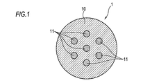
- FIG. 1 is a cross-sectional view showing an example of a multi-core optical fiber.
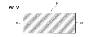
- FIG. 2A is a front view showing a glass body used in the optical fiber base material manufacturing method according to one aspect of the present disclosure.
- FIG. 2B is a cross-sectional view showing a glass body used in the optical fiber base material manufacturing method according to one aspect of the present disclosure.
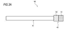
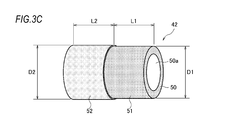
- FIG. 3A is a side view showing an example of a cutting tool according to one aspect of the present disclosure.
- FIG. 3B is a front view showing an example of a cutting tool according to one aspect of the present disclosure.
- FIG. 3C is an enlarged perspective view of the cutting portion of the cutting tools of FIGS. 3A and 3B to which the abrasive grains are fixed.
- FIG. 3A is a side view showing an example of a cutting tool according to one aspect of the present disclosure.
- FIG. 3B is a front view showing an example of a cutting tool according to one aspect of the present disclosure.
- FIG. 3C is
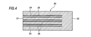
- FIG. 4 is a cross-sectional view including the central axis of the glass body in the step of producing the jacket material according to the embodiment of the present disclosure.
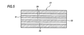
- FIG. 5 is a cross-sectional view including a central axis of the jacket material according to the embodiment of the present disclosure.
- FIG. 6 is a cross-sectional view including a central axis of the jacket material into which the core rod is inserted in the step of inserting the core rod according to the embodiment of the present disclosure.
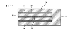
- FIG. 7 is a cross-sectional view including the central axis of the glass body in the step of producing the jacket material according to the modified example of the embodiment of the present disclosure.
- FIG. 8 is a cross-sectional view including a central axis of the jacket material according to a modified example of the embodiment of the present disclosure.
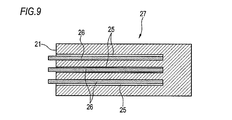
- FIG. 9 is a cross-sectional view including a central axis of the jacket material into which the core rod is inserted in the step of inserting the core rod according to the modified example of the embodiment of the present disclosure.
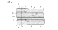
- FIG. 10 is a conceptual diagram showing an integration process according to the embodiment of the present disclosure.
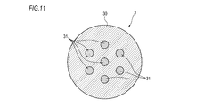
- FIG. 11 is a cross-sectional view showing an example of the jacket material.
- FIG. 12A is a front view showing another example of the cutting tool.
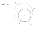
- FIG. 12B is a front view showing still another example of the cutting tool.
- a hole is provided in the center of the jacket pipe.
- the jacket pipe is heated from the outside, the jacket pipe deforms while maintaining a symmetrical state with respect to the central axis of the jacket pipe. That is, the inner circumference of the hole shrinks uniformly toward the central axis of the hole, and the inner wall of the hole contacts the core rod. At the same time as the inner circumference of the hole is reduced, the inner wall of the hole becomes smooth.
- the multi-core optical fiber base material is manufactured by the rod-in-collapse method, if the clearance between the inner diameter of the hole and the outer diameter of the core rod is small, the position accuracy of the core will be high. However, if the clearance is small, the inner wall of the hole is likely to come into contact with the core rod before the roughness of the inner wall of the hole is sufficiently reduced, so that air bubbles are likely to remain.
- Some multi-core optical fiber base materials have holes other than the center of the jacket pipe.
- the vicinity of the outer circumference of the jacket pipe is heated more strongly than the center of the jacket pipe. Therefore, in one cross section of the jacket pipe, it is difficult to keep the roughness of the inner wall of the hole other than the center of the jacket pipe equal over the entire circumference of the inner wall.
- the inner wall of the hole can come into contact with the core rod before the roughness of the inner wall of the portion of the inner wall of the hole near the center of the jacket pipe becomes sufficiently small, so that air bubbles are generated. It becomes easy to remain.
- a cutting tool including a shank portion and a cutting portion provided at one end of the shank portion.
- the cutting portion includes a first region provided at one end of the cutting tool and the first portion. It has a second region located closer to the center of the cutting tool than the region, and abrasive grains are fixed to the first region and the second region, and the average particle size of the abrasive grains in the second region is , Smaller than the average particle size of the abrasive grains in the first region.
- the present disclosure ensures the productivity of drilling in the first region and the inner wall of the hole in the second region. Roughness can be reduced. Therefore, in the present disclosure, it is possible to obtain an optical fiber base material in which air bubbles are less likely to remain at the boundary between the inner wall of the hole and the core rod without impairing the productivity of drilling.
- the abrasive grains are diamond grains.
- the abrasive grains are diamond grains.
- holes having a smooth inner wall are easily formed in the glass body.
- the average particle size of the abrasive grains in the first region is 100 ⁇ m or more, and the average particle size of the abrasive grains in the second region is less than 100 ⁇ m. Since the average particle size of the abrasive grains in the first region is 100 ⁇ m or more, the present disclosure can maintain a high drilling speed. Further, since the average particle size of the abrasive grains in the second region is less than 100 ⁇ m, the present disclosure can obtain a smooth inner wall even at the above processing speed.
- the outer diameter of the second region is larger than the outer diameter of the first region. Since the outer diameter of the second region is larger than the outer diameter of the first region, the second region can reliably process the inner wall of the hole after the first region has processed the hole. Therefore, the present disclosure can surely obtain a hole having a smooth inner wall.
- the difference between the outer diameter of the second region and the outer diameter of the first region is in the range of 10 ⁇ m or more and 300 ⁇ m or less. Since the difference between the outer diameter of the second region and the outer diameter of the first region is 10 ⁇ m or more, even if the abrasive grains of the second region are worn, the processing of the inner wall of the hole can be continued in the second region. .. Further, since the difference between the outer diameter of the second region and the outer diameter of the first region is 300 ⁇ m or less, the load on the second region during machining does not increase, and the wear of the abrasive grains in the second region is reduced. ..
- the optical fiber base material manufacturing method is a method for manufacturing an optical fiber base material having a core extending in the longitudinal direction, and the method is in the axial direction of the glass body.
- a jacket material is produced by forming a hole from one end to the other end using the cutting tool of the present disclosure, a core rod is inserted into the hole, and the jacket material is heated to form the jacket material and the core rod.
- the present disclosure ensures the productivity of drilling in the first region and the holes in the second region. The roughness of the inner wall of the can be reduced.
- the present disclosure it is possible to obtain an optical fiber base material in which air bubbles are less likely to remain at the boundary between the inner wall of the hole and the core rod without impairing the productivity of drilling. According to the present disclosure, by drawing the optical fiber base material produced in this manner, it is possible to produce an optical fiber having less variation in the outer diameter of the optical fiber and no decrease in mechanical strength.
- An object of the present disclosure is to provide a method for manufacturing an optical fiber base material and a cutting tool in which air bubbles are less likely to remain at the boundary between the inner wall of a hole and a core rod without impairing the productivity of drilling.
- FIG. 1 is a cross-sectional view showing an example of a multi-core optical fiber 1.
- the multi-core optical fiber 1 has, for example, seven cores 11 in the clad 10.
- the core 11 extends in the longitudinal direction of the multi-core optical fiber 1.
- the core 11 includes a central core arranged on the optical fiber central axis and an outer peripheral core arranged on the hexagonal vertices around the optical fiber central axis.
- Each core 11 includes a region having a refractive index higher than that of the clad 10 and is configured to propagate light.
- the rod-in-collapsing method includes, for example, a step of producing a jacket material by forming holes from one end to the other end in the axial direction of a cylindrical glass body, and a step of inserting a core rod into the holes of the jacket material. It has a step of heating the jacket material to integrate the jacket material and the core rod.
- FIG. 2A is a front view seen from one end 21 of the glass body 20 used in the optical fiber base material manufacturing method according to one aspect of the present disclosure.
- FIG. 2B is a cross-sectional view taken along the line XX of FIG. 2A.
- the glass body 20 is, for example, silica glass to which fluorine is added or pure silica glass, and has a cylindrical shape.
- the glass body 20 has seven holes extending from one end 21 to the other end 22 in the axial direction in a drill shape. Provided with a tool.
- FIG. 3A to 3C are diagrams illustrating a cutting tool 40 used in the optical fiber base material manufacturing method according to one aspect of the present disclosure.
- FIG. 3A is a side view showing an example of the cutting tool 40.
- FIG. 3B is a front view showing an example of the cutting tool 40.
- FIG. 3C is an enlarged perspective view of a cutting portion of the cutting tool 40 to which the abrasive grains are fixed.
- the cutting tool 40 includes a shank portion 41 and a cutting portion 42.
- the shank portion 41 is, for example, a hollow round bar made of metal, and is configured so that a rotational force around an axis extending in the longitudinal direction is applied to the shank portion 41.
- the cutting portion 42 is located in front of the shank portion 41 (one end of the cutting tool 40, which is the right side in FIG. 3A), and is configured to rotate together with the shank portion 41.
- the cutting portion 42 is, for example, a hollow round bar, and a discharge path 50a concentric with the shank portion 41 is provided at the center on the cross section of the cutting portion 42.
- the outer peripheral surface of the cutting portion 42 has a first region 51 provided at one end of the cutting tool 40 and a second region 52 located closer to the center of the cutting tool 40 than the first region 51.
- the second region 52 is located behind the first region 51 (on the left side in FIG. 3A).
- the front end of the second region 52 is connected to, for example, the rear end of the first region 51.
- the length L1 of the first region 51 and the length L2 of the second region 52 are both, for example, 5 mm.
- Abrasive grains (for example, diamond grains) are fixed to the first region 51 (including the tip surface 50) and the second region 52 by, for example, a multilayer electrodeposition structure.
- the average particle size of the abrasive grains is evaluated by the particle size specified in JIS_B_4130.
- the average particle size of the diamond grains in the first region 51 is 100 ⁇ m or more (# 140 or less in the particle size display in JIS_B_4130), preferably 150 ⁇ m or more (# 100 or less in the particle size display in JIS_B_4130).
- the average particle size of the diamond grains in the second region 52 is smaller than the average particle size of the diamond grains in the first region 51. Specifically, the average particle size of the diamond grains in the second region 52 is less than 100 ⁇ m, preferably 50 ⁇ m or less (# 270 or more in the particle size indication in JIS_B_4130).
- the average particle size is generally determined, for example, by a method of sorting particles by a plurality of types of sieves.
- the average particle size of 105 ⁇ m corresponds to the particle size display # 140
- the average particle size of 149 ⁇ m corresponds to # 100
- the average particle size of 53 ⁇ m corresponds to # 270.
- the present embodiment can maintain a high drilling speed.
- the present embodiment can further increase the processing speed of drilling.
- the average particle size of the diamond grains in the second region 52 is less than 100 ⁇ m, in the present embodiment, a smooth inner wall of holes can be obtained even at the above processing speed.
- the average particle size of the diamond grains in the second region 52 is 50 ⁇ m or less, the present embodiment can further smooth the inner wall of the hole.
- the amount of abrasive grains fixed to the cutting portion 42 is adjusted by dressing to form a cutting edge.
- the diamond may be a synthetic diamond or a natural diamond. Although diamond is suitable for processing glass, CBN (Cubic Boron Nitride: cubic boron nitride) may be used for the abrasive grains of the present disclosure.
- first region 51 and the second region 52 are connected.
- a region in which the abrasive grains do not adhere may be provided between the first region 51 and the second region 52, and the first region 51 and the second region 52 may be arranged apart from each other.
- the present embodiment is not limited to the two regions of the first region 51 and the second region 52, and three or more regions to which the abrasive grains are fixed may be provided. In this case, the average particle size of the abrasive grains in the region located at the rearmost position is the smallest.
- the outer diameter of the second region 52 and the outer diameter of the first region 51 may be the same size.
- the outer diameter D2 of the second region 52 is larger than the outer diameter D1 of the first region 51. This is because after the first region 51 provides the hole in the glass body 20, the second region can reliably process the inner wall of the hole. Thereby, in this embodiment, a hole having a smooth inner wall can be obtained.
- the difference (D2-D1) between the outer diameter D2 of the second region 52 and the outer diameter D1 of the first region 51 is in the range of 10 ⁇ m or more and 300 ⁇ m or less. Since the difference between the outer diameter D2 of the second region 52 and the outer diameter D1 of the first region 51 is 10 ⁇ m or more, even if the diamond grains of the second region 52 are worn by using the cutting tool 40 multiple times. , The second region 52 can continue to process the inner wall of the hole. In addition, since the difference between the outer diameter D2 of the second region 52 and the outer diameter D1 of the first region 51 is 300 ⁇ m or less, the load on the second region 52 during machining does not increase, and the load on the second region 52 does not increase. Diamond grain wear is reduced.
- the cutting tool 40 is rotationally driven, with the cutting portion 42 arranged in front at the head.
- the cutting tool 40 is inserted into the glass body 20 from one end 21 to the other end 22 of the glass body 20.
- the glass material cut by the cutting portion 42 is sent backward from, for example, the discharge path 50a and discharged.
- FIG. 4 to 6 are cross-sectional views including the central axis of the glass body 20 and the jacket material 27 in the method for manufacturing the optical fiber base material.
- a total of seven ring-shaped holes 28 are formed in the glass body 20 by the hollow round bar-shaped cutting tool 40.
- FIG. 4 shows an intermediate step in which three ring-shaped holes 28 on the cross section are formed out of a total of seven.
- An uncut rod 24 remains in the center of each ring-shaped hole 28.
- the through hole 29 corresponds to the hole of the present disclosure.
- the inner surface of the through hole 29 is cleaned with a fluorine-based gas or the like.
- FIG. 6 shows three core rods 26 on the cross section.
- the core rod 26 located at the center of the multi-core optical fiber 1 is arranged concentrically with the through hole 29 arranged on the central axis of the jacket material 27.
- the plurality of core rods 26 located on the outer peripheral core of the multi-core optical fiber 1 are arranged near the central axis of the jacket material 27 in the corresponding through holes 29.
- the hole of the present disclosure does not have to penetrate.
- a total of seven ring-shaped bottomed holes 23 are formed in the glass body 20.
- FIG. 7 shows three ring-shaped bottomed holes 23 on the cross section.
- the ring-shaped bottomed hole 23 corresponds to the hole of the present disclosure.
- the ring-shaped bottomed hole 23 extends along the longitudinal direction and reaches from the other end 22 to a position where a predetermined thickness is left.
- an uncut rod 24 surrounded by a ring-shaped bottomed hole 23 remains.
- FIG. 9 shows three core rods 26 on a cross section.
- the core rod 26 located at the center of the multi-core optical fiber 1 is arranged concentrically with the circular bottom hole 25 arranged on the central axis of the jacket material 27.
- the plurality of core rods 26 located in the outer peripheral core of the multi-core optical fiber 1 are arranged near the central axis of the jacket material 27 in the corresponding circular bottomed holes 25.
- the core rod 26 is a glass rod having a higher refractive index than the jacket material 27, and is manufactured by a vapor phase glass synthesis method such as a VAD (Vapor Phase Axial Deposition) method.
- a vapor phase glass synthesis method such as a VAD (Vapor Phase Axial Deposition) method.
- the core rod 26 is surrounded by a central core containing pure silica glass (which may contain chlorine) and the periphery of the central core, and fluorine is added.
- a core rod containing an optical clad containing silica glass is used.
- the core rod 26 contains an optical core containing silica glass to which GeO2 is added and pure silica glass that surrounds the center core and does not contain GeO2.
- a core rod containing a clad is used.
- FIG. 10 is a conceptual diagram showing an integration process according to the embodiment of the present disclosure.
- the jacket material 27 is heated to integrate the core rod 26 and the jacket material 27.
- the jacket material 27 into which the core rod 26 is inserted rotates, for example, around the central axis of the jacket material 27, and the heating source moves in the axial direction of the jacket material 27 (moves from right to left in FIG. 10). are doing.
- the jacket material 27 is heated, the inner diameter of the through hole 29 or the circular bottom hole 25 contracts due to surface tension, and the jacket material 27 is welded to the core rod 26.
- AA'in FIG. 10 indicates the position before the heating source passes.
- the core rod 26 and the jacket material 27 are not yet integrated.
- BB'in FIG. 10 indicates the position of the heating source in transit.
- the core rod 26 located on the outer peripheral core of the multi-core optical fiber 1 is already integrated with the jacket material 27.
- the jacket material 27 is not yet integrated with the core rod 26 located at the center of the multi-core optical fiber 1.
- CC'in FIG. 10 indicates the position after the heating source has passed. All core rods 26 and jacket material 27 are integrated. That is, at the position of CC'in FIG. 10, the cross-sectional structure of the multi-core optical fiber base material 3 as shown in FIG. 11 is formed, and the clad portion 30 and the core portion 31 are integrated.
- the through hole 29 or the circular bottomed hole 25 provided near the outer periphery of the jacket material 27 is provided in the center of the jacket material 27.
- the inner wall of the hole becomes smooth as the inner circumference of the hole shrinks, but the through hole 29 or the circular bottomed hole 25 provided near the outer periphery of the jacket material 27 has the through hole 29 or the circular bottom.
- the through hole 29 or the circular bottomed hole 25 may come into contact with the core rod 26 before the roughness of the inner wall of the inner wall of the hole 25 near the center of the jacket material 27 becomes sufficiently small. Further, when the clearance between the inner diameter of the through hole 29 or the circular bottom hole 25 and the outer diameter of the core rod 26 is small, the position accuracy of the core portion 31 described with reference to FIG. 11 becomes high, but the through hole 29 or the circular bottom hole 29 or the circular bottom hole is present. It becomes easy to contact the core rod 26 before the roughness of the inner wall of the bottom hole 25 becomes sufficiently small.
- the particle size of the diamond grains in the second region 52 of the cutting tool 40 is smaller than the particle size of the diamond grains in the first region 51, so that the first region 51 is a hole.
- the second region 52 reduces the roughness of the inner wall of the through hole 29 or the circular bottomed hole 25. Therefore, in the present embodiment, it is possible to obtain the multi-core optical fiber base material 3 in which air bubbles are less likely to remain at the boundary between the inner wall of the through hole 29 or the circular bottom hole 25 and the core rod 26 without impairing the productivity of drilling. it can. Then, in the present embodiment, by drawing the multi-core optical fiber base material 3 manufactured in this way, it is possible to manufacture the multi-core optical fiber 1 having less variation in outer diameter and no decrease in mechanical strength.
- FIGS. 12A and 12B an example of a hollow round bar-shaped cutting tool 40 has been described.
- the present disclosure is not limited to this example.
- a solid round bar-shaped cutting tool 40 as shown in FIGS. 12A and 12B may be used.
- the cutting tool 40 shown in FIG. 12A has, for example, five discharge paths 50a on the outer peripheral surface of the cutting portion 42.
- the tip surface 50 of the cutting portion 42 is, for example, conical.
- the cutting portion 42 has a smaller diameter than the through hole 29 or the circular bottomed hole 25. Then, the cutting portion 42 and the cut hole are not concentric, and the cutting portion 42 rotates about a position eccentric with respect to the center of the hole. In this case, since the cutting portion 42 has a smaller diameter than the hole, it is not necessary to provide a discharge path for the glass material.
- the tip surface 50 of the cutting portion 42 may be, for example, conical or cross-shaped.
- the method for manufacturing the multi-core optical fiber base material 3 has been described, but the present disclosure is also applicable to the case of manufacturing a single-core optical fiber base material.
- multi-core optical fiber 3 ... multi-core optical fiber base material, 10 ... clad, 11 ... core, 20 ... glass body, 21 ... one end, 22 ... other end, 23 ... ring-shaped bottomed hole, 24 ... uncut rod , 25 ... circular bottom hole, 26 ... core rod, 27 ... jacket material, 28 ... ring-shaped hole, 29 ... through hole, 30 ... clad part, 31 ... core part, 40 ... cutting tool, 41 ... shank part, 42 ... cutting portion, 50 ... tip surface, 50a ... discharge path, 51 ... first region, 52 ... second region.
Landscapes
- Engineering & Computer Science (AREA)
- Mechanical Engineering (AREA)
- Physics & Mathematics (AREA)
- Chemical & Material Sciences (AREA)
- Ceramic Engineering (AREA)
- Inorganic Chemistry (AREA)
- General Physics & Mathematics (AREA)
- Optics & Photonics (AREA)
- Life Sciences & Earth Sciences (AREA)
- General Life Sciences & Earth Sciences (AREA)
- Geochemistry & Mineralogy (AREA)
- Manufacturing & Machinery (AREA)
- Materials Engineering (AREA)
- Organic Chemistry (AREA)
- Manufacture, Treatment Of Glass Fibers (AREA)
- Polishing Bodies And Polishing Tools (AREA)
Priority Applications (3)
| Application Number | Priority Date | Filing Date | Title |
|---|---|---|---|
| CN202080022921.1A CN113613841B (zh) | 2019-03-28 | 2020-03-17 | 切削工具以及光纤母材制造方法 |
| JP2021509129A JP7639679B2 (ja) | 2019-03-28 | 2020-03-17 | 切削工具および光ファイバ母材製造方法 |
| US17/483,970 US20220011499A1 (en) | 2019-03-28 | 2021-09-24 | Cutting tool and method for manufacturing optical fiber preform |
Applications Claiming Priority (2)
| Application Number | Priority Date | Filing Date | Title |
|---|---|---|---|
| JP2019062449 | 2019-03-28 | ||
| JP2019-062449 | 2019-03-28 |
Related Child Applications (1)
| Application Number | Title | Priority Date | Filing Date |
|---|---|---|---|
| US17/483,970 Continuation US20220011499A1 (en) | 2019-03-28 | 2021-09-24 | Cutting tool and method for manufacturing optical fiber preform |
Publications (1)
| Publication Number | Publication Date |
|---|---|
| WO2020196104A1 true WO2020196104A1 (ja) | 2020-10-01 |
Family
ID=72610893
Family Applications (1)
| Application Number | Title | Priority Date | Filing Date |
|---|---|---|---|
| PCT/JP2020/011788 Ceased WO2020196104A1 (ja) | 2019-03-28 | 2020-03-17 | 切削工具および光ファイバ母材製造方法 |
Country Status (4)
| Country | Link |
|---|---|
| US (1) | US20220011499A1 (enExample) |
| JP (1) | JP7639679B2 (enExample) |
| CN (1) | CN113613841B (enExample) |
| WO (1) | WO2020196104A1 (enExample) |
Families Citing this family (1)
| Publication number | Priority date | Publication date | Assignee | Title |
|---|---|---|---|---|
| CN119858071A (zh) * | 2024-12-27 | 2025-04-22 | 清华大学 | 超声振动螺旋磨削方法 |
Citations (3)
| Publication number | Priority date | Publication date | Assignee | Title |
|---|---|---|---|---|
| JPS5641953Y2 (enExample) * | 1978-03-03 | 1981-10-01 | ||
| JPH02117861U (enExample) * | 1989-03-09 | 1990-09-20 | ||
| JP2014159348A (ja) * | 2013-02-20 | 2014-09-04 | Sumitomo Electric Ind Ltd | マルチコア光ファイバ母材製造方法 |
Family Cites Families (6)
| Publication number | Priority date | Publication date | Assignee | Title |
|---|---|---|---|---|
| JPS632826A (ja) * | 1986-06-23 | 1988-01-07 | Sumitomo Electric Ind Ltd | 光フアイバ母材の製造方法 |
| JP2521796B2 (ja) * | 1988-10-27 | 1996-08-07 | 沖電気工業株式会社 | 気体放電型発光装置の補助放電素子駆動回路 |
| US20070269282A1 (en) * | 2006-05-18 | 2007-11-22 | Agapiou John S | System and method of boring a pre-formed guide in a single pass |
| FR2975027B1 (fr) * | 2011-05-10 | 2014-04-18 | Snecma | Outil de percage de trous dans une piece, notamment en materiau composite a matrice organique, procede de percage correspondant |
| TW201325823A (zh) * | 2011-12-30 | 2013-07-01 | Metal Ind Res & Dev Ct | 磨削工具及其製作方法 |
| DE102013106612A1 (de) * | 2013-06-25 | 2015-01-08 | Schott Ag | Werkzeugkrone und mit der Werkzeugkrone herstellbares Glaskeramik-Erzeugnis |
-
2020
- 2020-03-17 CN CN202080022921.1A patent/CN113613841B/zh active Active
- 2020-03-17 WO PCT/JP2020/011788 patent/WO2020196104A1/ja not_active Ceased
- 2020-03-17 JP JP2021509129A patent/JP7639679B2/ja active Active
-
2021
- 2021-09-24 US US17/483,970 patent/US20220011499A1/en not_active Abandoned
Patent Citations (3)
| Publication number | Priority date | Publication date | Assignee | Title |
|---|---|---|---|---|
| JPS5641953Y2 (enExample) * | 1978-03-03 | 1981-10-01 | ||
| JPH02117861U (enExample) * | 1989-03-09 | 1990-09-20 | ||
| JP2014159348A (ja) * | 2013-02-20 | 2014-09-04 | Sumitomo Electric Ind Ltd | マルチコア光ファイバ母材製造方法 |
Also Published As
| Publication number | Publication date |
|---|---|
| CN113613841B (zh) | 2024-03-26 |
| CN113613841A (zh) | 2021-11-05 |
| US20220011499A1 (en) | 2022-01-13 |
| JPWO2020196104A1 (enExample) | 2020-10-01 |
| JP7639679B2 (ja) | 2025-03-05 |
Similar Documents
| Publication | Publication Date | Title |
|---|---|---|
| CN113939482A (zh) | 制造空芯光纤和空芯光纤预制件的方法 | |
| EP0147225A2 (en) | Method of forming an optical fiber | |
| KR20140127752A (ko) | 하이브리드 절삭공구, 칩 이송부 및 절삭공구를 제조하기 위한 방법 | |
| CN114127022A (zh) | 制造空芯光纤和空芯光纤预制件的方法 | |
| CN114007990A (zh) | 制造空芯光纤和空芯光纤预制件的方法 | |
| WO2020196104A1 (ja) | 切削工具および光ファイバ母材製造方法 | |
| CN114007991A (zh) | 制造空芯光纤和空芯光纤预制件的方法 | |
| CN114026049A (zh) | 制造空芯光纤和空芯光纤预制件的方法 | |
| CN105921793A (zh) | 一种钻头及其制造方法 | |
| US20210213543A1 (en) | Drill tip and method for producing a drill tip | |
| CN104249310B (zh) | 平头刀具和能用该平头刀具制造的玻璃或玻璃陶瓷制品 | |
| CN112399898A (zh) | 切削工具 | |
| JP2022116002A (ja) | 回転光ビーム発生装置 | |
| US20090117517A1 (en) | Dental crown preparation instrument and method for producing same | |
| US20010036339A1 (en) | Method of manufacturing glass parts for connecting optical fibers, and glass parts for connecting optical fibers manufactured using the methods | |
| CN220681240U (zh) | 一种pcd钻头 | |
| JP2002239847A (ja) | 部品成形用工具の加工方法及びこの加工方法を用いて製造された部品成形用工具 | |
| CN111344095B (zh) | 具有可变的刃圆曲度的螺纹刀片 | |
| JP2022540751A (ja) | 中空コアファイバの製造方法および中空コアファイバ用プリフォームの製造方法 | |
| JP2001047345A (ja) | 細孔加工方法 | |
| JP2008296331A (ja) | 加工装置 | |
| KR20200040124A (ko) | 샤프트 가공 장치 | |
| JP4374161B2 (ja) | 光学レンズ又はその金型の切削加工方法 | |
| JP2001106542A (ja) | 変形第1クラッドを有する光ファイバ母材の製造方法及び光ファイバ母材並びに光ファイバ | |
| WO2022176990A1 (ja) | マルチコア光ファイバ母材、マルチコア光ファイバ母材の製造方法およびマルチコア光ファイバの製造方法 |
Legal Events
| Date | Code | Title | Description |
|---|---|---|---|
| 121 | Ep: the epo has been informed by wipo that ep was designated in this application |
Ref document number: 20779340 Country of ref document: EP Kind code of ref document: A1 |
|
| ENP | Entry into the national phase |
Ref document number: 2021509129 Country of ref document: JP Kind code of ref document: A |
|
| NENP | Non-entry into the national phase |
Ref country code: DE |
|
| 122 | Ep: pct application non-entry in european phase |
Ref document number: 20779340 Country of ref document: EP Kind code of ref document: A1 |