WO2020195988A1 - Separator for secondary cell, thermoplastic resin granulated body, slurry composition, and method for manufacturing same, and secondary cell - Google Patents
Separator for secondary cell, thermoplastic resin granulated body, slurry composition, and method for manufacturing same, and secondary cell Download PDFInfo
- Publication number
- WO2020195988A1 WO2020195988A1 PCT/JP2020/011302 JP2020011302W WO2020195988A1 WO 2020195988 A1 WO2020195988 A1 WO 2020195988A1 JP 2020011302 W JP2020011302 W JP 2020011302W WO 2020195988 A1 WO2020195988 A1 WO 2020195988A1
- Authority
- WO
- WIPO (PCT)
- Prior art keywords
- thermoplastic resin
- separator
- particles
- median diameter
- secondary battery
- Prior art date
Links
Images

Classifications
-
- H—ELECTRICITY
- H01—ELECTRIC ELEMENTS
- H01M—PROCESSES OR MEANS, e.g. BATTERIES, FOR THE DIRECT CONVERSION OF CHEMICAL ENERGY INTO ELECTRICAL ENERGY
- H01M50/00—Constructional details or processes of manufacture of the non-active parts of electrochemical cells other than fuel cells, e.g. hybrid cells
- H01M50/40—Separators; Membranes; Diaphragms; Spacing elements inside cells
- H01M50/409—Separators, membranes or diaphragms characterised by the material
- H01M50/443—Particulate material
-
- B—PERFORMING OPERATIONS; TRANSPORTING
- B29—WORKING OF PLASTICS; WORKING OF SUBSTANCES IN A PLASTIC STATE IN GENERAL
- B29B—PREPARATION OR PRETREATMENT OF THE MATERIAL TO BE SHAPED; MAKING GRANULES OR PREFORMS; RECOVERY OF PLASTICS OR OTHER CONSTITUENTS OF WASTE MATERIAL CONTAINING PLASTICS
- B29B9/00—Making granules
-
- C—CHEMISTRY; METALLURGY
- C08—ORGANIC MACROMOLECULAR COMPOUNDS; THEIR PREPARATION OR CHEMICAL WORKING-UP; COMPOSITIONS BASED THEREON
- C08J—WORKING-UP; GENERAL PROCESSES OF COMPOUNDING; AFTER-TREATMENT NOT COVERED BY SUBCLASSES C08B, C08C, C08F, C08G or C08H
- C08J3/00—Processes of treating or compounding macromolecular substances
- C08J3/02—Making solutions, dispersions, lattices or gels by other methods than by solution, emulsion or suspension polymerisation techniques
- C08J3/03—Making solutions, dispersions, lattices or gels by other methods than by solution, emulsion or suspension polymerisation techniques in aqueous media
- C08J3/05—Making solutions, dispersions, lattices or gels by other methods than by solution, emulsion or suspension polymerisation techniques in aqueous media from solid polymers
-
- C—CHEMISTRY; METALLURGY
- C08—ORGANIC MACROMOLECULAR COMPOUNDS; THEIR PREPARATION OR CHEMICAL WORKING-UP; COMPOSITIONS BASED THEREON
- C08J—WORKING-UP; GENERAL PROCESSES OF COMPOUNDING; AFTER-TREATMENT NOT COVERED BY SUBCLASSES C08B, C08C, C08F, C08G or C08H
- C08J3/00—Processes of treating or compounding macromolecular substances
- C08J3/12—Powdering or granulating
-
- C—CHEMISTRY; METALLURGY
- C08—ORGANIC MACROMOLECULAR COMPOUNDS; THEIR PREPARATION OR CHEMICAL WORKING-UP; COMPOSITIONS BASED THEREON
- C08J—WORKING-UP; GENERAL PROCESSES OF COMPOUNDING; AFTER-TREATMENT NOT COVERED BY SUBCLASSES C08B, C08C, C08F, C08G or C08H
- C08J9/00—Working-up of macromolecular substances to porous or cellular articles or materials; After-treatment thereof
- C08J9/36—After-treatment
- C08J9/40—Impregnation
-
- H—ELECTRICITY
- H01—ELECTRIC ELEMENTS
- H01M—PROCESSES OR MEANS, e.g. BATTERIES, FOR THE DIRECT CONVERSION OF CHEMICAL ENERGY INTO ELECTRICAL ENERGY
- H01M50/00—Constructional details or processes of manufacture of the non-active parts of electrochemical cells other than fuel cells, e.g. hybrid cells
- H01M50/40—Separators; Membranes; Diaphragms; Spacing elements inside cells
- H01M50/489—Separators, membranes, diaphragms or spacing elements inside the cells, characterised by their physical properties, e.g. swelling degree, hydrophilicity or shut down properties
-
- Y—GENERAL TAGGING OF NEW TECHNOLOGICAL DEVELOPMENTS; GENERAL TAGGING OF CROSS-SECTIONAL TECHNOLOGIES SPANNING OVER SEVERAL SECTIONS OF THE IPC; TECHNICAL SUBJECTS COVERED BY FORMER USPC CROSS-REFERENCE ART COLLECTIONS [XRACs] AND DIGESTS
- Y02—TECHNOLOGIES OR APPLICATIONS FOR MITIGATION OR ADAPTATION AGAINST CLIMATE CHANGE
- Y02E—REDUCTION OF GREENHOUSE GAS [GHG] EMISSIONS, RELATED TO ENERGY GENERATION, TRANSMISSION OR DISTRIBUTION
- Y02E60/00—Enabling technologies; Technologies with a potential or indirect contribution to GHG emissions mitigation
- Y02E60/10—Energy storage using batteries
Definitions
- the present invention relates to a separator for a secondary battery, a thermoplastic resin granulated body, a slurry composition, a method for producing these, and a secondary battery.
- Secondary batteries such as lithium-ion batteries are widely used in portable digital devices such as mobile phones, laptop computers, digital cameras, digital video cameras, and portable game machines.
- portable digital devices such as mobile phones, laptop computers, digital cameras, digital video cameras, and portable game machines.
- the use as a power source for hybrid vehicles, electric vehicles, plug-in hybrid vehicles, etc. has been expanding for automobile applications.
- a separator for a secondary battery and an electrolyte are interposed between a positive electrode in which a positive electrode active material is laminated on a positive electrode current collector and a negative electrode in which a negative electrode active material is laminated on a negative electrode current collector. It has a configuration.
- a polyolefin-based porous substrate is used as the separator for the secondary battery.
- the characteristics required for a separator for a secondary battery are that it contains an electrolytic solution in a porous structure and enables ion transfer (ion conductivity), and that when a lithium ion battery overheats, it melts with heat.
- the porous structure is closed at, and the ion movement is stopped, so that the power generation is stopped (shutdown function).
- the separator for the secondary battery is required to have dimensional stability.
- the separator for secondary batteries is required to have not only the above characteristics but also further characteristics.
- the separator for the secondary battery is provided with an electrode impregnated with an electrolytic solution. Adhesiveness (wet adhesiveness) is required.
- the shape of the laminated body is maintained when the laminated body in which the positive electrode, the separator and the negative electrode are laminated is transported, and the wound positive electrode, the separator and the negative electrode are formed in a cylindrical shape. It is desired to improve productivity and battery performance by preventing the shape of the laminate from being deformed when pressed before being inserted into a mold such as a square mold. From such a viewpoint, the separator for a secondary battery is required to have adhesiveness (dry adhesiveness) between the separator and the electrode before being impregnated with the electrolytic solution. Further, with the spread of secondary batteries, it is required to reduce the manufacturing cost of the secondary battery, and the separator for the secondary battery is required to be reduced in cost.
- Patent Document 1 a separator for a secondary battery, which has less heat shrinkage and improved adhesion of inorganic particles to a porous body by holding a fluorine-containing polymer and a large amount of inorganic particles on a porous substrate, is used. Proposed.
- Patent Document 2 a porous layer containing a fluororesin, inorganic particles, and crosslinked polymer particles is laminated on a microporous film made of polyolefin, so that the electrode has less heat shrinkage and is impregnated with an electrolytic solution.
- a separator for a secondary battery which is provided with the adhesiveness (wet adhesiveness) of the above, has been proposed.
- Patent Document 1 since the fluorine-containing polymer is produced by the emulsion polymerization method, the particle size of the fluorine-containing polymer is small, and the adhesiveness (dry adhesiveness) between the separator and the electrode before impregnation with the electrolytic solution, and There is a problem that the adhesiveness (wet adhesiveness) between the separator and the electrode after impregnating with the electrolytic solution tends to be insufficient.
- Patent Document 2 it is necessary to use an organic solvent in which a fluorine-based resin is soluble as a solvent for the paint, and there is a problem that the environmental load is high and the cost tends to be high.
- an object of the present invention is to provide a separator for a secondary battery that can effectively suppress environmental load and cost while maintaining excellent adhesiveness, that is, dry adhesiveness or wet adhesiveness.
- the present inventors have excellent adhesion by using a thermoplastic resin granule containing a thermoplastic resin particle and a fused product in which the primary particles of a plurality of thermoplastic resin particles are fused as a separator for a secondary battery.
- the present invention was conceived by finding that property, that is, dry adhesiveness or wet adhesiveness can be obtained.
- the present invention has the following configuration. 1.
- a separator formed by laminating a porous layer on at least one surface of a porous base material, wherein a thermoplastic resin granule is contained in at least one surface layer of the porous layer, and the thermoplastic resin granulated body is thermoplastic.
- a separator for a secondary battery which is a granulated body containing resin particles and contains a fused product in which a plurality of primary particles of the thermoplastic resin particles are fused. 2.
- the ratio (A) of the median diameter of the thermoplastic resin granules to the median diameter of the thermoplastic resin particles constituting the thermoplastic resin granules represented by the following formula (1) is 10 or more and 250 or less.
- (A) Median diameter ( ⁇ m) of thermoplastic resin granules / Median diameter ( ⁇ m) of thermoplastic resin particles ... (1) 4.
- thermoplastic resin particles contain thermoplastic resin particles having a melting point of 50 ° C. or higher and 160 ° C. or lower.
- thermoplastic resin contains one or more kinds of polyvinylidene fluoride or a copolymer thereof or an acrylic resin.
- the porous layer contains an inorganic particle layer containing inorganic particles, and at least a part of the thermoplastic resin granulated body is buried inside the inorganic particle layer, and another part is the inorganic particles.
- the separator for a secondary battery according to any one of 1 to 6 above which projects outward from the surface of the layer. 8.
- Battery separator. (D) Thickness of inorganic particle layer ( ⁇ m) / Median diameter of thermoplastic resin granules ( ⁇ m) ... (4) 9.
- the inorganic particles are alumina, which are detected by energy dispersive X-ray spectroscopy (EDX) and are represented by the following formula (5), which is the ratio of the number of F pixels to the total number of F and Al pixels (E). ) Is 0.1 or more and 0.5 or less, the separator for a secondary battery according to 7 or 8 above.
- (E) number of pixels of F / (number of pixels of F + number of pixels of Al) ... (5) 10.
- the ratio (A) of the median diameter of the thermoplastic resin granules to the median diameter of the thermoplastic resin granules constituting the thermoplastic resin granules represented by the following formula (1) is 10 or more and 250 or less.
- (A) Median diameter ( ⁇ m) of thermoplastic resin granules / Median diameter ( ⁇ m) of thermoplastic resin particles ... (1) 14.
- thermoplastic resin granulated product according to any one of 12 to 16 wherein the thermoplastic resin contains one or more polyvinylidene fluoride or a copolymer thereof or an acrylic resin.
- the dispersion liquid is a dispersion liquid in which at least the inorganic particles and the thermoplastic resin granulated material are dispersed in a solvent, and the thermoplastic resin structure is represented by the following formula (2) with respect to the median diameter of the inorganic particles.
- (B) Median diameter ( ⁇ m) of thermoplastic resin granules / Median diameter ( ⁇ m) of inorganic particles ... (2) 21. 19.
- thermoplastic resin granulated body is contained in an amount of 1 wt% or more and 50 wt% or less.
- ratio (C) of the content of the thermoplastic resin granules to the content of the inorganic particles represented by the following formula (3) is 0.05 or more and 0.7 or less.
- Slurry composition. (C) Content of thermoplastic resin granules (wt%) / Content of inorganic particles (wt%) ... (3) 23.
- thermoplastic resin granulated product which comprises spray-drying and granulating the thermoplastic resin particles dispersed in a solvent with a spray dryer under a drying temperature condition below the melting point of the thermoplastic resin particles and above the glass transition point.
- a method for producing a slurry composition which comprises mixing the inorganic particles, a solvent, and the thermoplastic resin granules according to any one of 12 to 18 above.
- a secondary step including a step of applying and drying a slurry composition prepared by mixing the thermoplastic resin granules, inorganic particles, and a solvent according to any one of 12 to 18 on a porous substrate.
- the separator for a secondary battery of the present invention can effectively suppress the environmental load and cost while maintaining high adhesiveness, that is, dry adhesiveness or wet adhesiveness.
- FIG. 1 is an SEM image of an embodiment of a separator for a secondary battery of the present invention.
- FIG. 2 is a front sectional view schematically showing a method for measuring wet adhesive strength.
- the separator for a secondary battery according to the embodiment of the present invention is a separator formed by laminating a porous layer on at least one surface of a porous base material, and is obtained by thermoplastic resin granulation on at least one surface layer of the porous layer.
- the body is included, and the thermoplastic resin granules include a fused product in which a plurality of primary particles of the thermoplastic resin particles are fused.
- the separator for a secondary battery according to the embodiment of the present invention includes a step of applying and drying a slurry composition prepared by mixing a thermoplastic resin granulated body, inorganic particles, and a solvent on a porous substrate. It can be manufactured by a manufacturing method. Further, the separator for a secondary battery according to the embodiment of the present invention can be preferably used for a secondary battery. An embodiment of the present invention will be described in detail below.
- thermoplastic resin granulated body The thermoplastic resin granules according to the embodiment of the present invention are granules containing thermoplastic resin particles, and include a fused product in which primary particles of a plurality of thermoplastic resin particles are fused.
- the thermoplastic resin granule in the embodiment of the present invention is a granule containing thermoplastic resin particles, and takes a form in which a plurality of primary particles of the thermoplastic resin are fused at portions adjacent to each other. It is a state-like thermoplastic resin granule.
- thermoplastic resin granules of the present invention are porous in a slurry composition dispersed by applying a shearing force in a solvent, and in a separator for a secondary battery formed by applying and drying the slurry composition.
- the particle size and shape can be maintained without disintegrating the granules even in the layer, and high adhesiveness can be exhibited.
- the granules include secondary particles formed from a plurality of primary particles.
- the term "primary particle" as used herein means a particle that is considered to be a unit particle judging from its apparent geometrical morphology.
- thermoplastic resin granulated body according to the embodiment of the present invention can be preferably used for a separator for a secondary battery. Since the thermoplastic resin granules according to the embodiment of the present invention are granulated from a plurality of thermoplastic resin particles, they have voids inside the granules, and the solid particles having the same particle size can be used. It has a lower specific gravity than that. Therefore, when the slurry composition containing the thermoplastic resin granules according to the embodiment of the present invention is applied on a porous substrate and dried, it is more easily transferred to the surface of the dried film than the solid particles having the same particle size, and is adhered. Easy to express sex.
- thermoplastic resin granules according to the embodiment of the present invention have a large surface area as compared with a single particle having the same particle size because irregularities caused by a plurality of constituent thermoplastic resin particles are present on the surface. This is preferable because the bonding area becomes large.
- thermoplastic resin granule according to the embodiment of the present invention is a thermoplastic resin granule calculated by using the following formula (1) with respect to the median diameter of the thermoplastic resin granules constituting the thermoplastic resin granule.
- the ratio (A) of the median diameters of the above is preferably 10 or more and 250 or less.
- (A) Median diameter of thermoplastic resin granules ( ⁇ m) / Median diameter of thermoplastic resin particles ( ⁇ m) ... (1)
- the ratio (A) of the median diameter of the thermoplastic resin granules to the median diameter of the thermoplastic resin particles constituting the thermoplastic resin granules is 10 or more, the shape of the thermoplastic resin granules becomes indefinite. It is difficult to become, and it is possible to suppress deterioration of handleability due to a decrease in fluidity. Further, when the ratio is 250 or less, the proportion of the coarse fused body is unlikely to increase, and the variation in physical properties can be suppressed.
- the ratio (A) of the median diameter of the thermoplastic resin granules to the median diameter of the thermoplastic resin particles constituting the thermoplastic resin granules is more preferably 15 or more, further preferably 20 or more, and particularly preferably 30 or more. Similarly, such a ratio is more preferably 200 or less, further preferably 150 or less, and particularly preferably 100 or less.
- the median diameter of the thermoplastic resin granules is preferably 0.5 ⁇ m or more and 30 ⁇ m or less. When the median diameter is 0.5 ⁇ m or more, the contact area with the adherend is unlikely to be small, and sufficient adhesiveness, that is, dry adhesiveness or wet adhesiveness can be obtained. On the other hand, when the median diameter is 30 ⁇ m or less, the decrease in dispersion stability is suppressed and it is difficult to settle in the slurry.
- the median diameter of the thermoplastic resin granules is more preferably 1 ⁇ m or more, further preferably 1.5 ⁇ m or more, further preferably 2 ⁇ m or more, and particularly preferably 9 ⁇ m or more. The median diameter is more preferably 25 ⁇ m or less, further preferably 20 ⁇ m or less, and particularly preferably 15 ⁇ m or less.
- the median diameter of the thermoplastic resin particles constituting the thermoplastic resin granules according to the embodiment of the present invention is preferably 0.01 ⁇ m or more and 1 ⁇ m or less.
- the median diameter of the thermoplastic resin particles is more preferably 0.05 ⁇ m or more, further preferably 0.1 ⁇ m or more.
- the median diameter of the thermoplastic resin particles is more preferably 0.7 ⁇ m or less, further preferably 0.4 ⁇ m or less.
- the median diameter is 0.01 ⁇ m or more, the thermoplastic resin particles are less likely to aggregate before granulation, and a uniform granulated material is easily formed.
- the median diameter is 1 ⁇ m or less, the contact area between the thermoplastic resin particles inside the thermoplastic resin granules is unlikely to be small, and it is possible to prevent the thermoplastic resin granules from becoming brittle.
- the thermoplastic resin used in the embodiment of the present invention contains at least one type of thermoplastic resin having a low glass transition point in order to promote fusion between the thermoplastic resin particles.
- the above-mentioned thermoplastic resin is preferably a non-crosslinked thermoplastic resin as compared with a crosslinked thermoplastic resin.
- the thermoplastic resin having a low glass transition point is not particularly limited, but for example, an olefin resin such as polyethylene or polypropylene, an acrylic resin, a styrene-butadiene resin, a methyl methacrylate-styrene copolymer, or a polyamide.
- thermoplastic resin contains one or more kinds of polyvinylidene fluoride (PVdF) or a copolymer thereof or an acrylic resin.
- the thermoplastic resin is more preferably polyvinylidene fluoride (PVdF) or a copolymer thereof.
- the copolymerizing component constituting the PVdF copolymer that is, the fluoromonopolymer that can be copolymerized with vinylidene fluoride (VDF) is not particularly limited, but vinyl fluoride, trifluoroethylene, and tetrafluoro. Examples thereof include ethylene, chlorotrifluoroethylene (CTFE), hexafluoropropylene (HFP), and perfluoroalkyl vinyl ether typified by perfluoromethyl vinyl ether.
- CTFE chlorotrifluoroethylene
- HFP hexafluoropropylene
- perfluoroalkyl vinyl ether typified by perfluoromethyl vinyl ether.
- the copolymer of VDF and HFP is particularly preferable because of its high chemical and physical stability with respect to the non-aqueous electrolytic solution.
- thermoplastic resin granules according to the embodiment of the present invention preferably granulate PVdF having a small particle size synthesized by an emulsion polymerization method or a copolymer thereof, thereby having a median diameter of more than 0.7 ⁇ m and 50 ⁇ m. Easy to obtain less than granules.
- the glass transition point of the thermoplastic resin is preferably 80 ° C. or lower.
- the glass transition point of the thermoplastic resin is preferably ⁇ 100 ° C. or higher, more preferably ⁇ 80 ° C. or higher, and even more preferably ⁇ 60 ° C. or higher.
- the glass transition point of the thermoplastic resin is more preferably 50 ° C. or lower, and even more preferably 20 ° C. or lower.
- thermoplastic resin granules and the thermoplastic resin particles The glass transition points of the thermoplastic resin granules and the thermoplastic resin particles can be measured by the method described in Examples.
- the melting point of the thermoplastic resin is preferably 50 ° C. or higher and 160 ° C. or lower.
- the melting point of the thermoplastic resin is preferably 50 ° C. or higher, more preferably 55 ° C. or higher, and even more preferably 60 ° C. or higher.
- the melting point of the thermoplastic resin is preferably 150 ° C. or lower, more preferably 130 ° C. or lower, further preferably 110 ° C. or lower, further preferably 100 ° C. or lower, and particularly preferably 80 ° C. or lower.
- the melting point is 50 ° C. or higher, the thermoplastic resin granules are difficult to fuse with each other during storage and handling, and the formation of coarse agglomerates can be suppressed.
- the melting point is 150 ° C. or lower, high-temperature treatment is not required to develop dry adhesiveness, and handleability is improved.
- the melting point of the thermoplastic resin is preferably 120 ° C. or higher, more preferably 130 ° C. or higher, and even more preferably 140 ° C. or higher.
- the melting point of the thermoplastic resin is preferably 160 ° C. or lower, more preferably 155 ° C. or lower, further preferably 150 ° C. or lower, and particularly preferably 145 ° C. or lower.
- the melting point is 120 ° C. or higher, the solubility in the electrolytic solution tends to be low, and the wet adhesiveness is easily maintained for a long period of time.
- the melting point is 160 ° C.
- thermoplastic resin granules and the thermoplastic resin particles The melting points of the thermoplastic resin granules and the thermoplastic resin particles can be measured by the method described in Examples.
- the melting point of the thermoplastic resin can be controlled by adjusting the ratio of the copolymerization components.
- the melting point decreases as the copolymerization component (HFP) ratio increases.
- the copolymerization component ratio of the VDF-HFP copolymer is preferably 0.3 mol% or more and 20 mol% or less.
- the copolymerization component ratio is preferably 9 mol% or more, more preferably 10 mol% or more, still more preferably 12 mol% or more.
- the copolymerization component ratio is preferably 20 mol% or less, more preferably 18 mol% or less, further preferably 16 mol% or less, and particularly preferably 14 mol% or less.
- the copolymerization component ratio is 9 mol% or more, thermal deformation is likely to occur, and sufficient dry adhesiveness is likely to be exhibited by treatment at a lower temperature.
- the copolymerization component ratio is 20 mol% or less, fusion to the wall surface of the granulator tends to be suppressed during granulation described later, and a high yield can be easily obtained.
- the copolymerization component ratio is preferably 0.3 mol% or more, more preferably 1 mol% or more, further preferably 2 mol% or more, and particularly preferably 3 mol% or more.
- the copolymerization component ratio is preferably 9 mol% or less, more preferably 8 mol% or less, further preferably 6 mol% or less, particularly preferably 5 mol% or less, and even more preferably 4 mol% or less.
- the copolymerization component ratio is 0.3 mol% or more, the crystallinity of the polymer is suppressed and the degree of swelling due to the electrolytic solution tends to be high, so that wet adhesion is easy.
- the copolymerization component ratio is 9 mol% or less, the solubility in the electrolytic solution tends to be low, and the wet adhesiveness is easily maintained for a long period of time.
- thermoplastic resin granulated body the thermoplastic resin particles dispersed in a solvent are preferably spray-dried under a drying temperature condition of less than the melting point of the thermoplastic resin particles and higher than the glass transition point. It can be produced by a production method including spray-drying granulation.
- the granulation method is not particularly limited, and can be produced by using known production methods such as rolling granulation method, fluid granulation method, rolling fluid granulation method, spray drying granulation method, and mixed granulation method. ..
- the spray-dry granulation method is preferable because it does not require additives such as coagulants that adversely affect the battery characteristics.
- the spray-drying granulation method is not limited to this, but is preferably performed using a spray-dryer (spray dryer).
- spray drying granulation method using a spray dryer will be referred to as a spray drying method.
- the method of drying and granulating by the spray drying granulation method is not particularly limited, and for example, the thermoplastic resin particle dispersion liquid is formed into a fine mist and is preferably ejected into hot air at 30 ° C. or higher and 160 ° C. or lower. Just let me do it.
- the temperature of the hot air is more preferably 40 ° C. or higher, further preferably 50 ° C. or higher, and particularly preferably 60 ° C. or higher.
- the temperature of the hot air is more preferably 130 ° C. or lower, further preferably 100 ° C. or lower, and particularly preferably 80 ° C. or lower. By setting the temperature of the hot air to 160 ° C.
- thermoplastic resin granule containing a fused product in which the primary particles of the plurality of thermoplastic resin particles are fused.
- various known methods such as a centrifugal spraying method using a rotating disk and a pressure spraying method using a pressure nozzle are used. Can be adopted.
- the slurry composition according to the embodiment of the present invention is a dispersion liquid in which the above-mentioned thermoplastic resin granules are dispersed in a solvent.
- the slurry composition is preferably a dispersion in which inorganic particles and thermoplastic resin granules are dispersed in a solvent, and is a thermoplastic resin granules represented by the following formula (2) with respect to the median diameter of the inorganic particles.
- the ratio (B) of the median diameters of the above is preferably 3 or more and 100 or less.
- (B) Median diameter ( ⁇ m) of thermoplastic resin granules / Median diameter ( ⁇ m) of inorganic particles ... (2)
- the ratio (B) of the median diameter of the thermoplastic resin granulated material to the median diameter of the inorganic particles is 3 or more, the thermoplastic resin granulated material is hidden behind the inorganic particles and the exposed area to the outermost surface of the porous layer. Can be suppressed from decreasing, and the adhesiveness is less likely to decrease.
- the ratio (B) of the median diameter of the thermoplastic resin granulated material to the median diameter of the inorganic particles is 100 or less, the thermoplastic resin granulated material does not easily block the porous structure formed by the inorganic particles, and the air permeability is increased. Can be suppressed.
- the ratio (B) of the median diameter of the thermoplastic resin granulated material to the median diameter of the inorganic particles is more preferably 4 or more, further preferably 9 or more, and particularly preferably 14 or more. Similarly, such a ratio is more preferably 80 or less, further preferably 60 or less, and particularly preferably 40 or less.
- the inorganic particles include calcium carbonate, calcium phosphate, amorphous silica, crystalline glass filler, kaolin, talc, titanium dioxide, alumina, magnesia, magnesium hydroxide, silica-alumina composite oxide particles, barium sulfate, and the like.
- Calcium fluoride, lithium fluoride, zeolite, molybdenum sulfide, mica, boehmite and the like can be mentioned. These inorganic particles may be used alone or in combination of two or more.
- the median diameter of the inorganic particles is preferably 0.05 ⁇ m or more, more preferably 0.20 ⁇ m or more, and even more preferably 0.30 ⁇ m or more.
- the median diameter of the inorganic particles is preferably 5.0 ⁇ m or less, more preferably 3.0 ⁇ m or less, and even more preferably 1.0 ⁇ m or less.
- the median diameter of the inorganic particles is 0.05 ⁇ m or more, it is possible to prevent the porous layer from becoming dense and the air permeability from becoming high. Further, it is possible to suppress the decrease in the impregnation property of the electrolytic solution due to the reduction of the pore diameter, and improve the productivity.
- the median diameter of the inorganic particles is 5.0 ⁇ m or less, sufficient dimensional stability can be obtained, the increase in the film thickness of the porous layer can be suppressed, and the battery characteristics can be improved.
- the shape of the inorganic particles is not particularly limited and may be any shape, and examples thereof include a spherical shape, a plate shape, a needle shape, a rod shape, and an elliptical shape, and any shape may be used. ..
- the content of the thermoplastic resin granulated body in the slurry composition is preferably 1 wt% or more and 50 wt% or less.
- the content of the thermoplastic resin granules is 1 wt% or more, the amount of exposure of the thermoplastic resin granules to the surface of the porous layer is unlikely to decrease, and the decrease in adhesiveness can be suppressed.
- the content of the thermoplastic resin granulated body is 50 wt% or less, the thermoplastic resin granulated body does not easily block the porous structure, and an increase in air permeability can be suppressed.
- the content of the thermoplastic resin granulated body is more preferably 3 wt% or more, further preferably 5 wt% or more, and particularly preferably 7 wt% or more.
- the content of the thermoplastic resin granulated body is more preferably 30 wt% or less, further preferably 20 wt% or less, and particularly preferably 12 wt% or less.
- the ratio (C) of the content of the thermoplastic resin granules to the content of the inorganic particles represented by the following formula (3) is 0.05 or more and 0. It is preferably 7 or less.
- (C) Content of thermoplastic resin granules (wt%) / Content of inorganic particles (wt%) ...
- the ratio (C) of the content of the thermoplastic resin granules to the content of the inorganic particles is 0.05 or more, the thermoplastic resin granules are difficult to be embedded in a large amount of inorganic particles, and the surface of the porous layer is covered. It is possible to suppress the decrease in adhesiveness due to the decrease in the amount of exposure. Further, when the ratio is 0.7 or less, the inorganic particles necessary for maintaining the structure of the porous layer are less likely to be insufficient, and the increase in heat shrinkage can be suppressed.
- the ratio (C) of the content of the thermoplastic resin granules to the content of the inorganic particles is more preferably 0.07 or more, further preferably 0.1 or more, and particularly preferably 0.15 or more. Similarly, such a ratio is more preferably 0.5 or less, further preferably 0.4 or less, and particularly preferably 0.35 or less.
- a solvent containing water as a main component is preferable from the viewpoint of suppressing impregnation of the solvent into the porous substrate.
- the main component refers to a component contained in an amount of 50% by mass or more in 100% by mass of the solvent.
- the ratio of water to the solvent containing water as a main component is preferably 50% by mass or more, more preferably 60% by mass or more, and further preferably 70% by mass or more.
- the proportion of water is 50% by mass or more, it is difficult for the coating liquid to impregnate the substrate when coating the porous substrate, and it is easy to form a desired porous layer.
- the environmental load and cost are effective as compared with the case of using an organic solvent in which a fluororesin is soluble. Can be suppressed.
- An organic resin may be added to the slurry composition according to the embodiment of the present invention, if necessary.
- a dispersant may be used if necessary.
- the type of dispersant is not particularly limited, and for example, a cationic surfactant such as an alkylamine salt or a quaternary ammonium salt, an alkyl sulfate ester salt, a polyoxyethylene alkyl ether sulfate ester salt, an alkylbenzene sulfonate, Anionic surfactants such as fatty acid salts, nonionic surfactants such as polyoxyethylene alkyl ethers, polyoxyethylene alkylphenols, glycerin fatty acid esters, polyoxyethylene fatty acid esters, and amphoteric surfactants such as alkyl betaine and alkyl amine oxides.
- a cationic surfactant such as an alkylamine salt or a quaternary ammonium salt
- an alkyl sulfate ester salt such as an alkyl sulfate ester salt, a polyoxyethylene alkyl ether sulfate ester salt, an alky
- dispersants include polymer compounds such as polyvinylpyrrolidone, polycarboxylic acid salts, polysulfonates, and polyethers. These dispersants may be used alone or in admixture of two or more.
- the amount of the dispersant added is preferably 0.1 part by mass or more and 40 parts by mass or less, more preferably 0.2, based on 100 parts by mass of the total of the thermoplastic resin granulated body, the organic resin, and the inorganic particles to be dispersed. It is by mass or more, more preferably 0.5 parts by mass or more.
- the amount of the dispersant added is preferably 30 parts by mass or less, more preferably 20 parts by mass or less. When the amount of the dispersant added is 40 parts by mass or less, it is possible to prevent the content of the thermoplastic resin granulated body from being reduced in the porous layer and suppress the deterioration of the adhesiveness.
- thermoplastic resin granules As a method for dispersing the thermoplastic resin granules, the organic resin, and the inorganic particles, a known method may be used. For example, ball mills, bead mills, sand mills, roll mills, homogenizers, ultrasonic homogenizers, high-pressure homogenizers, ultrasonic devices, paint shakers and the like can be mentioned. These plurality of mixing and dispersing machines may be combined to perform dispersion in stages.
- the slurry composition according to the embodiment of the present invention can be produced by a production method including mixing inorganic particles, a solvent, and the above-mentioned thermoplastic resin granules.
- the above slurry composition can be used as a coating liquid for coating a porous substrate for the purpose of being used for a separator for a secondary battery described later.
- the order in which the coating liquid is prepared is not particularly limited. From the viewpoint of improving the efficiency of the dispersion process, a dispersant is added and mixed with a solvent containing water as a main component, and a thermoplastic resin granulated body, an organic resin, and inorganic particles are added to the solution to apply a coating solution. It is preferable to prepare.
- an organic resin may be added to the coating liquid in order to bind the particles to each other or the particles to the porous base.
- an antioxidant, a stabilizer, an antifoaming agent, a leveling agent and the like may be added to the coating liquid as appropriate.
- the type of leveling agent is not particularly limited, but for example, cationic surfactants such as alkylamine salts and quaternary ammonium salts, alkyl sulfate ester salts, polyoxyethylene alkyl ether sulfate ester salts, alkylbenzene sulfonates, etc.
- Anionic surfactants such as fatty acid salts, nonionic surfactants such as polyoxyethylene alkyl ethers, polyoxyethylene alkylphenols, glycerin fatty acid esters, polyoxyethylene fatty acid esters, and amphoteric surfactants such as alkyl betaine and alkyl amine oxides.
- cationic, anionic, nonionic, amphoteric fluorine-based surfactants silicon-based surfactants, polyvinylpyrrolidone, polycarboxylates, polysulfonates, and polymer compounds such as polyethers.
- leveling agents may be used alone or in combination of two or more.
- the amount of the leveling agent added is preferably 20 parts by mass or less, more preferably 10 parts by mass or less, still more preferably 5 parts by mass, based on 100 parts by mass of the total of the thermoplastic resin granulated body, the organic resin, and the inorganic particles. It is as follows. When the amount of the leveling agent added is 20 parts by mass or less, it is possible to suppress a decrease in adhesiveness and a decrease in battery characteristics due to a side reaction in the secondary battery.
- the separator for a secondary battery according to the embodiment of the present invention is a separator formed by laminating a porous layer on at least one surface of a porous base material, and is obtained by thermoplastic resin granulation on at least one surface layer of the porous layer.
- the separator for a secondary battery according to the embodiment of the present invention is a separator formed by laminating a porous layer on at least one surface of a porous base material, and the above-mentioned heat is applied to at least one surface layer of the porous layer. It is preferable to contain a plastic resin granule.
- the porous layer contains an inorganic particle layer containing inorganic particles, and at least a part of the thermoplastic resin granulated body is inorganic. It is characterized in that it is buried inside the particle layer and other parts protrude outward from the surface of the inorganic particle layer.
- the separator for a secondary battery according to the embodiment of the present invention can be suitably used for a secondary battery such as a lithium ion battery.
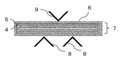
- FIG. 1 is an SEM image of an embodiment of the separator for a secondary battery of the present invention.
- the separator for a secondary battery according to the embodiment of the present invention is formed by laminating a porous layer on at least one surface of the porous base material 1.
- the porous layer includes an inorganic particle layer 2 containing inorganic particles, and further contains a thermoplastic resin granulated body 3 on at least one surface layer of the porous layer.
- the thermoplastic resin granulated material 3 may be attached to the surface of the inorganic particle layer 2 without being buried inside.
- thermoplastic resin granules 3 In order to prevent the thermoplastic resin granules from falling off from the porous layer and to stably develop the adhesiveness, at least a part of the thermoplastic resin granules 3 is inside the inorganic particle layer 2. It is preferable that the particle is buried in the inorganic particle layer 2 and the other portion projects outward from the surface of the inorganic particle layer 2.
- the ratio (D) of the thickness of the inorganic particle layer to the median diameter of the thermoplastic resin granules calculated from the following formula (4) is 0.02 or more 1
- the following is preferable.
- (D) Thickness of inorganic particle layer ( ⁇ m) / Median diameter of thermoplastic resin granules ( ⁇ m) ... (4)
- the ratio (D) of the thickness of the inorganic particle layer to the median diameter of the thermoplastic resin granulated material is 0.02 or more, the thermoplastic resin granulated material does not easily protrude from the surface of the inorganic particle layer and is porous during handling of the separator. It can be suppressed from falling off from the quality layer, and sufficient adhesion to the electrode can be obtained.
- the ratio (D) of the thickness of the inorganic particle layer to the median diameter of the thermoplastic resin granule is 1 or less, the thermoplastic resin granule is difficult to be buried in the inorganic particle layer and is easily brought into contact with the electrode, which is sufficient. Adhesiveness is obtained.
- the ratio of the thickness of the inorganic particle layer to the median diameter of the thermoplastic resin granule is more preferably 0.05 or more, further preferably 0.10 or more, and particularly preferably 0.15 or more. Similarly, such a ratio is more preferably 0.8 or less, further preferably 0.6 or less, and particularly preferably 0.4 or less.
- the thickness of the inorganic particle layer is preferably 0.10 ⁇ m or more. More preferably, the thickness of the inorganic particle layer is 0.3 ⁇ m or more, and even more preferably 0.5 ⁇ m or more. Similarly, the thickness of the inorganic particle layer is preferably 5.0 ⁇ m or less, more preferably 4.0 ⁇ m or less, and even more preferably 3.0 ⁇ m or less. When the thickness of the inorganic particle layer is 0.10 ⁇ m or more, the thermoplastic resin granules are less likely to fall off from the porous layer during handling of the separator, and sufficient adhesiveness to the electrode can be obtained.
- the inorganic particle layer on both sides of the porous base material.
- the difference in thickness of the inorganic particle layers on each surface is preferably 1 ⁇ m or less for the same reason.
- the surface roughness of the porous layer of the separator for a secondary battery according to the embodiment of the present invention is preferably 0.4 ⁇ m or more and 15 ⁇ m or less.
- the surface roughness is 0.4 ⁇ m or more, the protrusion of the thermoplastic resin granules from the surface of the inorganic particle layer is unlikely to be small, and the adhesiveness is sufficient.
- it is 15 ⁇ m or less, it is possible to suppress the embedding of the thermoplastic resin granules in the inorganic particle layer from becoming small, and prevent the thermoplastic resin granules from falling off during handling of the separator.
- the surface roughness is more preferably 1.0 ⁇ m or more, and further preferably 1.5 ⁇ m or more.
- the surface roughness is more preferably 10 ⁇ m or less, further preferably 5 ⁇ m or less.
- the inorganic particles are alumina
- the fluorine (F) is measured by energy dispersive X-ray spectroscopy (EDX) and calculated from the following formula (5).
- the ratio (E) of the number of pixels of fluorine (F) to the total number of pixels of aluminum (Al) is preferably 0.1 or more and 0.5 or less.
- (E) number of pixels of F / (number of pixels of F + number of pixels of Al) ... (5)
- the ratio (E) of the number of fluorine pixels to the total number of fluorine and aluminum pixels is 0.1 or more, the distribution of the fluorine-containing thermoplastic resin granules on the surface layer of the inorganic particle layer becomes small. It can be suppressed and the adhesiveness can be improved. Further, when it is 0.5 or less, the number of inorganic particles required for maintaining the structure of the inorganic particle layer is sufficient, and it is possible to suppress an increase in thermal shrinkage.
- the ratio (E) of the number of pixels of fluorine to the total number of pixels of fluorine and aluminum is more preferably 0.12 or more, further preferably 0.14 or more, and particularly preferably 0.16 or more. Similarly, 0.4 or less is more preferable, 0.3 or less is further preferable, and 0.25 or less is particularly preferable.
- a slurry composition prepared by mixing the above-mentioned thermoplastic resin granules, inorganic particles, and a solvent is applied (coated) on a porous substrate.
- a slurry composition prepared by mixing the above-mentioned thermoplastic resin granules, inorganic particles, and a solvent is applied (coated) on a porous substrate.
- a coating method a known method may be used for coating. For example, gravure coating, slit die coating, knife coating, kiss coating, roll coating, bar coating, spray coating, dip coating, spin coating, screen printing, inkjet printing, pad printing, and other types of printing are available.
- the coating method is not limited to these, and is appropriately selected according to preferable conditions such as the thermoplastic resin granulated material to be used, the organic resin, the inorganic particles, the binder, the dispersant, the leveling agent, the solvent to be used, and the base material. do it. Further, in order to improve the coatability, for example, the surface treatment of the coated surface such as corona treatment or plasma treatment may be performed on the porous substrate.
- one side When laminating a porous layer on both sides of a porous base material, one side may be coated and dried, or both sides may be coated and dried at the same time. It is more productive and preferable to apply and dry both sides at the same time.
- the porous layer on both sides rather than laminating the porous layer on only one side. This is because by laminating the porous layers on both sides, adhesiveness can be obtained on both the positive electrode and the negative electrode, so that the process handling is excellent.
- examples of the porous substrate include a porous membrane having pores inside, a non-woven fabric, and a porous membrane sheet made of a fibrous material.
- the material constituting the porous base material is preferably composed of a resin that is electrically insulating, electrically stable, and stable to an electrolytic solution.
- the resin used is preferably a thermoplastic resin having a melting point of 200 ° C. or lower.
- the shutdown function here is a function of closing the porous structure by melting with heat when the lithium ion battery generates abnormal heat, stopping the ion movement, and stopping the power generation.
- thermoplastic resin used for the porous base material examples include polyolefin-based resins.
- the porous substrate is preferably a polyolefin-based porous substrate.
- the polyolefin-based porous substrate is more preferably a polyolefin-based porous substrate having a melting point of 200 ° C. or lower.
- Specific examples of the polyolefin-based resin include polyethylene, polypropylene, copolymers thereof, and mixtures thereof.
- examples thereof include a multilayer porous base material made of polypropylene.
- a method for producing a porous base material a method of forming a polyolefin resin into a sheet and then stretching it to make it porous, or a method of dissolving a polyolefin resin in a solvent such as liquid paraffin to form a sheet and then extracting the solvent. There is a method of making it porous.
- the thickness of the porous substrate is preferably 3 ⁇ m or more and 50 ⁇ m or less.
- the thickness of the porous substrate is 50 ⁇ m or less, it is possible to suppress an increase in the internal resistance of the porous substrate. Further, when the thickness of the porous substrate is 3 ⁇ m or more, it is easy to manufacture and sufficient mechanical properties can be obtained.
- the thickness of the porous substrate is more preferably 5 ⁇ m or more. Similarly, the thickness of the porous substrate is more preferably 30 ⁇ m or less.
- the air permeability of the porous substrate is preferably 50 seconds / 100 cc or more and 1000 seconds / 100 cc or less. More preferably, it is 500 seconds / 100 cc or less. When the air permeability is 1000 seconds / 100 cc or less, sufficient ion mobility can be obtained and deterioration of battery characteristics can be suppressed. When the air permeability of the porous substrate is 50 seconds / 100 cc or more, sufficient mechanical properties can be obtained.
- the secondary battery according to the embodiment of the present invention is a secondary battery using the above-mentioned separator for a secondary battery.
- the secondary battery preferably includes a secondary battery such as a lithium ion battery.
- Lithium-ion batteries generally have a configuration in which a separator for a secondary battery and an electrolyte are interposed between a positive electrode in which a positive electrode active material is laminated on a positive electrode current collector and a negative electrode in which a negative electrode active material is laminated on a negative electrode current collector. Have.
- the positive electrode is obtained by laminating a positive electrode material composed of an active material, a binder resin, a conductive auxiliary agent, etc. on a current collector, and examples of the active material include LiCoO 2 , LiNiO 2 , Li (NiComn) O 2 , and the like. Examples thereof include lithium-containing transition metal oxides having a layered structure, spinel-type manganese oxides such as LiMn 2 O 4 , and iron-based compounds such as LiFePO 4 .
- the binder resin a resin having high oxidation resistance may be used. Specific examples thereof include fluorine-based resins, acrylic-based resins, and styrene-butadiene-based resins.
- the conductive auxiliary agent a carbon material such as carbon black or graphite is used.
- As the current collector a metal foil is preferable, and aluminum is often used in particular.
- the negative electrode is a negative electrode material composed of an active material, a binder resin, a conductive auxiliary agent, etc. laminated on a current collector, and the active material is a carbon material such as artificial graphite, natural graphite, hard carbon, or soft carbon. , Lithium alloy materials such as tin and silicon, metal materials such as Li, and lithium titanate (Li 4 Ti 5 O 12 ).
- the binder resin a fluorine-based resin, an acrylic resin, a styrene-butadiene resin, or the like is used.
- the conductive auxiliary agent carbon black, graphite and the like are used.
- As the current collector a metal foil is suitable, and in particular, a copper foil is often used.
- the electrolytic solution is a place for moving ions between the positive electrode and the negative electrode in the secondary battery, and has a configuration in which the electrolyte is dissolved in an organic solvent.
- the electrolyte include LiPF 6 , LiBF 4 , LiClO 4 , and the like.
- LiPF 6 is preferably used from the viewpoint of solubility in an organic solvent and ionic conductivity.
- the organic solvent include ethylene carbonate, propylene carbonate, fluoroethylene carbonate, dimethyl carbonate, diethyl carbonate, ethyl methyl carbonate, gamma-butyrolactone, sulfolane and the like. These organic solvents may be used alone or in admixture of two or more.
- an active material and a conductive auxiliary agent are dispersed in a binder solution to prepare a coating solution for electrodes, and this coating solution is applied onto a current collector to dry the solvent.
- a positive electrode and a negative electrode can be obtained, respectively.
- the film thickness of the coating film after drying is preferably 50 ⁇ m or more and 500 ⁇ m or less.
- a separator for a secondary battery is placed between the obtained positive electrode and the negative electrode so as to be in contact with the active material layer of each electrode, sealed in an exterior material such as an aluminum laminate film, injected with an electrolytic solution, and then heat-pressed. .. After that, a negative electrode lead and a safety valve are installed to seal the exterior material. Since the secondary battery thus obtained has good adhesiveness between the electrode and the separator for the secondary battery, it has excellent cycle characteristics, excellent dimensional stability, and can be manufactured at low cost. ..
- the measurement was started when the ultrasonic waves were applied at the intensity of 6 for 1 minute, and the ultrasonic waves were continuously applied until the end of the measurement.
- Water was used as the solvent in the apparatus, and the absolute refractive index of the PVdF copolymer was 1.41.
- the dry adhesive strength (N / m) was measured by the peel method (180 ° peeling, peeling speed 100 mm / min) using the Tensilon universal tester RTG-1210 manufactured by A & D Co., Ltd.
- the load cell was equipped with TLU-5N-G (maximum load capacity 5N) and measured continuously during the period of 100 mm from the start of measurement to the end of measurement.
- the average value of the load of 20 to 60 mm was calculated and converted into the value per 1 m of width to obtain the peel strength (dry adhesive strength).
- a part of the porous layer may remain on the porous substrate side, but in this case as well, it was calculated as the peel strength (dry adhesive strength) between the negative electrode and the porous layer.
- FIG. 2 is a front sectional view schematically showing a method for measuring wet adhesive strength. Details will be described below with reference to FIG.
- test winding body (Preparation of test winding body)
- the negative electrode 5 (machine direction 161 mm ⁇ width direction 30 mm) produced above and the produced secondary battery separator 4 (machine direction 160 mm ⁇ width direction 34 mm) are overlapped with each other to form a metal plate (length 300 mm, width 25 mm, thickness).
- the secondary battery separator 4 and the negative electrode 5 were wound around the winding core (1 mm) so that the secondary battery separator 4 was on the inside, and the metal plate was pulled out to obtain a test winding body 7.
- the test wound body had a length of about 34 mm and a width of about 28 mm.
- test winding body 7 was placed in a bag-shaped laminated film 6 in which three of the four sides were welded. .. 500 ⁇ L of an electrolytic solution prepared by dissolving LiPF 6 at a ratio of 1 mol / L in a solvent in which ethylene carbonate and ethyl methyl carbonate are mixed at a volume ratio of 3: 7 is injected through the opening of the laminate film 6 in a glove box, and a test roll is used. The body 7 was impregnated, and one side of the opening was sealed with a vacuum sealer.
- test winding body 7 enclosed in the laminate film 6 is sandwiched between two gaskets (thickness 1 mm, 5 cm ⁇ 5 cm), and a precision heating and pressurizing device (CYPT-10 manufactured by Shinto Kogyo Co., Ltd.).
- the pressure was increased at 98 ° C. and 0.6 MPa for 2 minutes, and the mixture was allowed to cool at room temperature.
- the wet adhesive strength of the test winding body 7 after pressurization was measured using a universal testing machine (AGS-J, manufactured by Shimadzu Corporation) while being sealed in the laminate film 6.
- Two aluminum L-shaped angles 8 are arranged in parallel so that the 90 ° part faces up, with the ends aligned, and the 90 ° part is the fulcrum. It was fixed so that the distance between them was 15 mm.
- the aluminum L-shaped angle 8 is made by aligning the midpoint of the width direction side (about 28 mm) of the test winding body with the 7.5 mm point, which is the middle of the distance between the fulcrums of the two aluminum L-shaped angles 8.
- the test winding body 7 was arranged so as not to protrude from the side in the length direction of.
- the side (about 34 mm) in the length direction of the test winding body protrudes from the side in the length direction of the aluminum L-shaped angle 9 (thickness 1 mm, 10 mm ⁇ 10 mm, length 4 cm).
- the three test winding bodies were measured at a load speed of 0.5 mm / min, and the average value of the obtained maximum test forces was taken as the wet adhesive strength (N).
- the observation field of view was determined at an accelerating voltage of 4.5 kV and a magnification of 1,000 times, and an electron beam image was captured at a resolution of 4096, and then mapping was performed at a resolution of 4096. Phase analysis was performed on the mapping results, and the ratio of the number of pixels of fluorine to the total number of pixels of fluorine and aluminum was calculated.
- VDF / HFP 88/12
- Alumina particles (median diameter 0.5 ⁇ m) as inorganic particles were mixed with the above thermoplastic resin granules by adding water so that the mass ratio of the non-volatile solid content was 25:75.
- 3.9 parts by mass of acrylic resin was added as a binder to 100 parts by mass of the total of the thermoplastic resin granulated body and the inorganic particles, and a perfluoroalkyl compound as a surfactant was granulated by the thermoplastic resin as a leveling agent.
- a slurry composition was prepared by adding 0.4 parts by mass with respect to 100 parts by mass of the total of the body and the inorganic particles. The solid content concentration of the obtained slurry composition was 45 wt%.
- This slurry composition was coated on both sides of a polyethylene porous base material (thickness 9 ⁇ m, air permeability 175 sec / 100 cc) so that the thickness of the inorganic particle layer was 0.7 ⁇ m per side using a bar coater.
- the coated slurry composition was dried in a hot air oven at 50 ° C. for 2 min to form a porous layer, and a separator for a secondary battery according to the embodiment of the present invention was obtained.
- Example 2 A separator for a secondary battery according to an embodiment of the present invention was obtained in the same manner as in Example 1 except that the slurry composition was coated using a bar coater so that the thickness of the inorganic particle layer was 1.5 ⁇ m per side. It was.
- Example 3 A separator for a secondary battery according to an embodiment of the present invention was obtained in the same manner as in Example 1 except that the slurry composition was coated using a bar coater so that the thickness of the inorganic particle layer was 2.0 ⁇ m per side. It was.
- Example 4 A separator for a secondary battery according to an embodiment of the present invention was obtained in the same manner as in Example 1 except that the slurry composition was coated using a bar coater so that the thickness of the inorganic particle layer was 3.0 ⁇ m per side. It was.
- Example 5 A separator for a secondary battery according to an embodiment of the present invention was obtained in the same manner as in Example 3 except that the hot air temperature of the spray dryer was changed to 70 ° C.
- Example 6 A separator for a secondary battery according to an embodiment of the present invention was obtained in the same manner as in Example 3 except that the hot air temperature of the spray dryer was changed to 90 ° C.
- Example 7 According to the second embodiment of the present invention in the same manner as in Example 3 except that the thermoplastic resin granules in the slurry composition and the non-volatile solids of the inorganic particles are mixed so as to have a mass ratio of 10:90. A separator for the next battery was obtained.
- Example 9 A separator for a secondary battery according to an embodiment of the present invention was obtained in the same manner as in Example 3 except that alumina particles having a median diameter of 0.05 ⁇ m were used as the inorganic particles.
- Example 10 A separator for a secondary battery according to an embodiment of the present invention was obtained in the same manner as in Example 1 except that a thermoplastic resin granulated body having a median diameter of 1 ⁇ m recovered by spray drying with a spray dryer and then recovered with a cyclone was used.
- Example 11 Using a thermoplastic resin granule with a median diameter of 2 ⁇ m and alumina particles with a median diameter of 1 ⁇ m recovered by spray drying with a spray dryer and then recovering with a cyclone, using a bar coater so that the thickness of the inorganic particle layer is 4.0 ⁇ m per side. The slurry composition was applied. A separator for a secondary battery according to an embodiment of the present invention was obtained in the same manner as in Example 1 except for the above.
- Example 12 According to the second embodiment of the present invention in the same manner as in Example 3 except that the thermoplastic resin granules in the slurry composition and the non-volatile solids of the inorganic particles are mixed so as to have a mass ratio of 3:97. A separator for the next battery was obtained.
- Example 13 A thermoplastic resin granule having a median diameter of 2 ⁇ m recovered by spray drying with a spray dryer and then recovered with a cyclone was used, and the slurry composition was coated with a bar coater so that the thickness of the inorganic particle layer was 4.0 ⁇ m per side.
- a separator for a secondary battery according to an embodiment of the present invention was obtained in the same manner as in Example 1 except for the above.
- Example 14 A separator for a secondary battery according to an embodiment of the present invention was obtained in the same manner as in Example 6 except that a spray dryer L-8i manufactured by Ohkawara Kakohki Co., Ltd. was used and the spraying method was changed to centrifugal spraying.
- Vinylidene fluoride-hexafluoropropylene copolymer (VDF / HFP 88/12) particles having a median diameter of 0.7 ⁇ m produced by an emulsion polymerization method without granulation with a spray dryer were used in the slurry composition.
- a separator for a secondary battery was obtained in the same manner as in Example 3 except for the above.
- Vinylidene fluoride-hexafluoropropylene copolymer (VDF / HFP 95/5) particles having a median diameter of 0.7 ⁇ m produced by an emulsion polymerization method without granulation with a spray dryer were used in the slurry composition.
- a separator for a secondary battery was obtained in the same manner as in Example 3 except for the above.
- a separator for a secondary battery was obtained in the same manner as in Example 3 except for the above.
- a separator for a secondary battery was obtained in the same manner as in Example 3 except for the above.
- a large amount of sedimentation which was considered to be vinylidene fluoride-hexafluoropropylene copolymer particles, was observed in the slurry composition, and streaks dragging the copolymer particles were observed in the coating film.
- thermoplastic resin particles Glass transition point of thermoplastic resin particles used in each Example and Comparative Example, melting point of thermoplastic resin particles, weight average molecular weight of thermoplastic resin particles, median diameter of thermoplastic resin particles, composition of thermoplastic resin particles, heat Manufacturing method of thermoplastic resin granules, median diameter of thermoplastic resin granules, ratio of median diameter of thermoplastic resin granules to median diameter of thermoplastic resin particles (A), solvent of slurry composition, slurry composition Inorganic particle median diameter in, ratio of the median diameter of the thermoplastic resin granulated body to the median diameter of the inorganic particles in the slurry composition (B), the content of the thermoplastic resin granulated body in the slurry composition, the slurry composition Tables 1 to 3 show the mass ratio of the thermoplastic resin granulated product to the inorganic particles at the time of manufacturing the product, and the ratio (C) of the content of the thermoplastic resin granulated product to the content of the inorganic particles in the slurry composition. Shown in.
- the thickness of the inorganic particle layer (one side), the median diameter of the thermoplastic resin granulated body, and the median diameter of the thermoplastic resin granulated body of the inorganic particle layer.
- the thickness ratio (D), air permeability, surface roughness, dry adhesive strength, wet adhesive strength, and the ratio of the number of F pixels to the total number of F and Al particles detected by EDX (E) were measured. ..
- the measurement results are shown in Tables 1 to 3.
- each numerical value calculated by using the median diameter of the thermoplastic resin granules was calculated by using the median diameter of the thermoplastic resin particles.
- FIG. 1 is an SEM image of the separator for a secondary battery of Example 1.
- the separator for a secondary battery according to the embodiment of the present invention is formed by laminating a porous layer on at least one surface of a porous base material, and a thermoplastic resin on at least one surface layer of the porous layer. Includes granulated body.
- FIG. 2 is a front sectional view schematically showing a method for measuring the wet adhesive strength shown in Measurement Example 9.
- a separator for a secondary battery that can effectively suppress environmental load and cost while maintaining excellent adhesiveness, that is, dry adhesiveness or wet adhesiveness.
Abstract
The present invention relates to a separator for a secondary cell, in which a porous layer is layered on at least one surface of a porous substrate, wherein the separator includes a thermoplastic resin granulated body in at least one surface layer of the porous layer, and the thermoplastic resin granulated body includes thermoplastic resin particles, and includes a fused material in which primary particles of a plurality of the thermoplastic resin particles are fused.
Description
本発明は、二次電池用セパレータ、熱可塑性樹脂造粒体、スラリー組成物、及びこれらの製造方法、並びに二次電池に関する。
The present invention relates to a separator for a secondary battery, a thermoplastic resin granulated body, a slurry composition, a method for producing these, and a secondary battery.
リチウムイオン電池のような二次電池は、携帯電話、ノートパソコン、デジタルカメラ、デジタルビデオカメラ、携帯ゲーム機などのポータブルデジタル機器に広く用いられている。近年は自動車用途として、ハイブリッド車、電気自動車、プラグインハイブリッド車などの電源としての使用が拡大してきている。
Secondary batteries such as lithium-ion batteries are widely used in portable digital devices such as mobile phones, laptop computers, digital cameras, digital video cameras, and portable game machines. In recent years, the use as a power source for hybrid vehicles, electric vehicles, plug-in hybrid vehicles, etc. has been expanding for automobile applications.
リチウムイオン電池は、一般的に、正極活物質を正極集電体に積層した正極と、負極活物質を負極集電体に積層した負極との間に、二次電池用セパレータと電解質が介在した構成を有している。
In a lithium ion battery, generally, a separator for a secondary battery and an electrolyte are interposed between a positive electrode in which a positive electrode active material is laminated on a positive electrode current collector and a negative electrode in which a negative electrode active material is laminated on a negative electrode current collector. It has a configuration.
二次電池用セパレータとしては、ポリオレフィン系多孔質基材が用いられている。二次電池用セパレータに求められる特性としては、多孔構造中に電解液を含み、イオン移動を可能にする特性(イオン伝導性)と、リチウムイオン電池が異常発熱した場合に、熱で溶融することで多孔構造が閉鎖され、イオン移動を停止させることで、発電を停止させる特性(シャットダウン機能)が挙げられる。また、高温時に二次電池用セパレータが熱収縮することで発生する正極と負極の接触による短絡を防ぐために、二次電池用セパレータには寸法安定性が求められている。
A polyolefin-based porous substrate is used as the separator for the secondary battery. The characteristics required for a separator for a secondary battery are that it contains an electrolytic solution in a porous structure and enables ion transfer (ion conductivity), and that when a lithium ion battery overheats, it melts with heat. The porous structure is closed at, and the ion movement is stopped, so that the power generation is stopped (shutdown function). Further, in order to prevent a short circuit due to contact between the positive electrode and the negative electrode caused by heat shrinkage of the separator for the secondary battery at a high temperature, the separator for the secondary battery is required to have dimensional stability.
加えて、近年のリチウムイオン電池の高容量化、高出力化に伴い、二次電池用セパレータには前記特性のみならず、更なる特性が求められている。例えば、充放電を繰り返すことで電極と二次電池用セパレータの間に隙間が発生しサイクル特性が悪化することを防ぐために、二次電池用セパレータには、電解液を含浸した状態での電極との接着性(ウェット接着性)が求められている。
In addition, with the recent increase in capacity and output of lithium ion batteries, the separator for secondary batteries is required to have not only the above characteristics but also further characteristics. For example, in order to prevent a gap from being generated between the electrode and the separator for the secondary battery due to repeated charging and discharging and deterioration of the cycle characteristics, the separator for the secondary battery is provided with an electrode impregnated with an electrolytic solution. Adhesiveness (wet adhesiveness) is required.
また、二次電池の製造工程において、正極、セパレータ、負極を積層した積層体を運搬する際に積層体の形を維持することや、捲回した正極、セパレータ、負極の積層体を円筒型、角型などの型に挿入する前にプレスする際に積層体の形が崩れないようにすることにより、生産性や電池性能を改善することが望まれている。このような観点からは、二次電池用セパレータには電解液を含浸する前のセパレータと電極との接着性(ドライ接着性)が求められている。さらには、二次電池の普及に伴い、二次電池の製造コストを下げることが求められており、二次電池用セパレータには低コスト化が求められている。
Further, in the manufacturing process of the secondary battery, the shape of the laminated body is maintained when the laminated body in which the positive electrode, the separator and the negative electrode are laminated is transported, and the wound positive electrode, the separator and the negative electrode are formed in a cylindrical shape. It is desired to improve productivity and battery performance by preventing the shape of the laminate from being deformed when pressed before being inserted into a mold such as a square mold. From such a viewpoint, the separator for a secondary battery is required to have adhesiveness (dry adhesiveness) between the separator and the electrode before being impregnated with the electrolytic solution. Further, with the spread of secondary batteries, it is required to reduce the manufacturing cost of the secondary battery, and the separator for the secondary battery is required to be reduced in cost.
特許文献1では、含フッ素重合体と多量の無機粒子を多孔質基材上に保持させることで、熱収縮が少なく、無機粒子の多孔質体への密着力を向上した二次電池用セパレータが提案されている。
In Patent Document 1, a separator for a secondary battery, which has less heat shrinkage and improved adhesion of inorganic particles to a porous body by holding a fluorine-containing polymer and a large amount of inorganic particles on a porous substrate, is used. Proposed.
特許文献2では、フッ素系樹脂と無機粒子と架橋高分子粒子を含む多孔質層をポリオレフィンからなる微多孔膜上に積層することで、熱収縮が少なく、電解液を含浸した状態での電極との接着性(ウェット接着性)が付与された二次電池用セパレータが提案されている。
In Patent Document 2, a porous layer containing a fluororesin, inorganic particles, and crosslinked polymer particles is laminated on a microporous film made of polyolefin, so that the electrode has less heat shrinkage and is impregnated with an electrolytic solution. A separator for a secondary battery, which is provided with the adhesiveness (wet adhesiveness) of the above, has been proposed.
特許文献1では、含フッ素重合体を乳化重合法で製造しているため含フッ素重合体の粒径が小さく、電解液を含浸する前のセパレータと電極との接着性(ドライ接着性)、および電解液を含浸した後のセパレータと電極との接着性(ウェット接着性)が不十分になりやすいという課題があった。
In Patent Document 1, since the fluorine-containing polymer is produced by the emulsion polymerization method, the particle size of the fluorine-containing polymer is small, and the adhesiveness (dry adhesiveness) between the separator and the electrode before impregnation with the electrolytic solution, and There is a problem that the adhesiveness (wet adhesiveness) between the separator and the electrode after impregnating with the electrolytic solution tends to be insufficient.
また、特許文献2では、塗料の溶媒としてフッ素系樹脂を可溶な有機溶剤を用いる必要があり、環境高負荷ならびに高コストになりやすいという課題があった。
Further, in Patent Document 2, it is necessary to use an organic solvent in which a fluorine-based resin is soluble as a solvent for the paint, and there is a problem that the environmental load is high and the cost tends to be high.
本発明は上記課題に鑑み、優れた接着性、即ちドライ接着性またはウェット接着性を保持しながら環境負荷およびコストを効果的に抑制できる二次電池用セパレータを提供することを目的とする。
In view of the above problems, an object of the present invention is to provide a separator for a secondary battery that can effectively suppress environmental load and cost while maintaining excellent adhesiveness, that is, dry adhesiveness or wet adhesiveness.
本発明者らは、熱可塑性樹脂粒子を含み、複数の熱可塑性樹脂粒子の一次粒子が融着した融着物を含む熱可塑性樹脂造粒体を二次電池用セパレータに用いることにより、優れた接着性、即ちドライ接着性またはウェット接着性が得られることを見出し、本発明に想到した。
The present inventors have excellent adhesion by using a thermoplastic resin granule containing a thermoplastic resin particle and a fused product in which the primary particles of a plurality of thermoplastic resin particles are fused as a separator for a secondary battery. The present invention was conceived by finding that property, that is, dry adhesiveness or wet adhesiveness can be obtained.
上記課題を解決するため本発明は次の構成を有する。
1.多孔質基材の少なくとも片面に多孔質層を積層してなるセパレータであって、前記多孔質層の少なくとも一方の表層に熱可塑性樹脂造粒体を含み、前記熱可塑性樹脂造粒体は熱可塑性樹脂粒子を含む造粒体であって、複数の前記熱可塑性樹脂粒子の一次粒子が融着した融着物を含む、二次電池用セパレータ。
2.前記熱可塑性樹脂造粒体のメジアン径が0.5μm以上30μm以下である、前記1に記載の二次電池用セパレータ。
3.下記式(1)で表される、前記熱可塑性樹脂造粒体を構成する前記熱可塑性樹脂粒子のメジアン径に対する前記熱可塑性樹脂造粒体のメジアン径の比(A)が、10以上250以下である、前記1または2に記載の二次電池用セパレータ。
(A)=熱可塑性樹脂造粒体のメジアン径(μm)/熱可塑性樹脂粒子のメジアン径(μm)…(1)
4.前記熱可塑性樹脂粒子が、ガラス転移点が80℃以下の熱可塑性樹脂粒子を含む、前記1~3のいずれか1に記載の二次電池用セパレータ。
5.前記熱可塑性樹脂粒子が、融点が50℃以上、160℃以下の熱可塑性樹脂粒子を含む、前記1~4のいずれか1に記載の二次電池用セパレータ。
6.前記熱可塑性樹脂が、ポリフッ化ビニリデン若しくはその共重合体またはアクリル系樹脂を1種以上含む、前記1~5のいずれか1に記載の二次電池用セパレータ。
7.前記多孔質層が無機粒子を含む無機粒子層を含み、少なくとも一部の前記熱可塑性樹脂造粒体は、一部分が前記無機粒子層の内部に埋没しており、かつ他の部分が前記無機粒子層の表面から外側に突出している、前記1~6のいずれか1に記載の二次電池用セパレータ。
8.下記式(4)で表される、前記熱可塑性樹脂造粒体のメジアン径に対する前記無機粒子層の厚みの比(D)が、0.02以上1以下である、前記7に記載の二次電池用セパレータ。
(D)=無機粒子層の厚み(μm)/熱可塑性樹脂造粒体のメジアン径(μm)…(4)
9.前記無機粒子がアルミナであって、エネルギー分散型X線分光法(EDX)で検出され、下記式(5)で表される、FとAlのピクセル数の合計に対するFのピクセル数の比(E)が0.1以上0.5以下である、前記7または8に記載の二次電池用セパレータ。
(E)=Fのピクセル数/(Fのピクセル数+Alのピクセル数)…(5)
10.前記多孔質層の面粗さが0.4μm以上15μm以下である、前記1~9のいずれか1に記載の二次電池用セパレータ。
11.前記1~10のいずれか1に記載の二次電池用セパレータを用いる二次電池。
12.熱可塑性樹脂粒子を含む造粒体であって、複数の前記熱可塑性樹脂粒子の一次粒子が融着した融着物を含む、熱可塑性樹脂造粒体。
13.下記式(1)で表される、前記熱可塑性樹脂造粒体を構成する前記熱可塑性樹脂粒子のメジアン径に対する前記熱可塑性樹脂造粒体のメジアン径の比(A)が、10以上250以下である、前記12に記載の熱可塑性樹脂造粒体。
(A)=熱可塑性樹脂造粒体のメジアン径(μm)/熱可塑性樹脂粒子のメジアン径(μm)…(1)
14.前記熱可塑性樹脂造粒体のメジアン径が0.5μm以上30μm以下である、前記12または13に記載の熱可塑性樹脂造粒体。
15.前記熱可塑性樹脂粒子が、ガラス転移点が80℃以下の熱可塑性樹脂粒子を含む、前記12~14のいずれか1に記載の熱可塑性樹脂造粒体。
16.前記熱可塑性樹脂粒子が、融点が50℃以上、160℃以下の熱可塑性樹脂粒子を含む、前記12~15のいずれか1に記載の熱可塑性樹脂造粒体。
17.前記熱可塑性樹脂が、ポリフッ化ビニリデン若しくはその共重合体またはアクリル系樹脂を1種以上含む、前記12~16のいずれか1に記載の熱可塑性樹脂造粒体。
18.二次電池用セパレータ用である、前記12~17のいずれか1に記載の熱可塑性樹脂造粒体。
19.少なくとも前記12~18のいずれか1に記載の熱可塑性樹脂造粒体が溶媒に分散した分散液を含むスラリー組成物。
20.前記分散液が、少なくとも無機粒子と、前記熱可塑性樹脂造粒体が溶媒に分散した分散液であって、下記式(2)で表される、前記無機粒子のメジアン径に対する前記熱可塑性樹脂造粒体のメジアン径の比(B)が、3以上100以下である、前記19に記載のスラリー組成物。
(B)=熱可塑性樹脂造粒体のメジアン径(μm)/無機粒子のメジアン径(μm)…(2)
21.前記熱可塑性樹脂造粒体を1wt%以上50wt%以下含む、前記19または20に記載のスラリー組成物。
22.下記式(3)で表される、前記無機粒子の含有量に対する前記熱可塑性樹脂造粒体の含有量の比(C)が0.05以上0.7以下である、前記20または21に記載のスラリー組成物。
(C)=熱可塑性樹脂造粒体の含有量(wt%)/無機粒子の含有量(wt%)…(3)
23.溶媒に分散した熱可塑性樹脂粒子を、熱可塑性樹脂粒子の融点未満、ガラス転移点以上の乾燥温度条件でスプレードライヤーにより噴霧乾燥造粒することを含む、熱可塑性樹脂造粒体の製造方法。
24.無機粒子、溶媒、および前記12~18のいずれか1に記載の熱可塑性樹脂造粒体を混合することを含む、スラリー組成物の製造方法。
25.前記12~18のいずれか1に記載の熱可塑性樹脂造粒体、無機粒子、および溶媒を混合して作製したスラリー組成物を、多孔質基材上に塗布、乾燥する工程を含む、二次電池用セパレータの製造方法。 In order to solve the above problems, the present invention has the following configuration.
1. 1. A separator formed by laminating a porous layer on at least one surface of a porous base material, wherein a thermoplastic resin granule is contained in at least one surface layer of the porous layer, and the thermoplastic resin granulated body is thermoplastic. A separator for a secondary battery, which is a granulated body containing resin particles and contains a fused product in which a plurality of primary particles of the thermoplastic resin particles are fused.
2. 2. The separator for a secondary battery according to 1 above, wherein the thermoplastic resin granule has a median diameter of 0.5 μm or more and 30 μm or less.
3. 3. The ratio (A) of the median diameter of the thermoplastic resin granules to the median diameter of the thermoplastic resin particles constituting the thermoplastic resin granules represented by the following formula (1) is 10 or more and 250 or less. The separator for a secondary battery according to 1 or 2 above.
(A) = Median diameter (μm) of thermoplastic resin granules / Median diameter (μm) of thermoplastic resin particles ... (1)
4. The separator for a secondary battery according to any one of 1 to 3 above, wherein the thermoplastic resin particles contain thermoplastic resin particles having a glass transition point of 80 ° C. or lower.
5. The separator for a secondary battery according to any one of 1 to 4, wherein the thermoplastic resin particles contain thermoplastic resin particles having a melting point of 50 ° C. or higher and 160 ° C. or lower.
6. The separator for a secondary battery according to any one of 1 to 5 above, wherein the thermoplastic resin contains one or more kinds of polyvinylidene fluoride or a copolymer thereof or an acrylic resin.
7. The porous layer contains an inorganic particle layer containing inorganic particles, and at least a part of the thermoplastic resin granulated body is buried inside the inorganic particle layer, and another part is the inorganic particles. The separator for a secondary battery according to any one of 1 to 6 above, which projects outward from the surface of the layer.
8. The secondary according to 7 above, wherein the ratio (D) of the thickness of the inorganic particle layer to the median diameter of the thermoplastic resin granulated material represented by the following formula (4) is 0.02 or more and 1 or less. Battery separator.
(D) = Thickness of inorganic particle layer (μm) / Median diameter of thermoplastic resin granules (μm) ... (4)
9. The inorganic particles are alumina, which are detected by energy dispersive X-ray spectroscopy (EDX) and are represented by the following formula (5), which is the ratio of the number of F pixels to the total number of F and Al pixels (E). ) Is 0.1 or more and 0.5 or less, the separator for a secondary battery according to 7 or 8 above.
(E) = number of pixels of F / (number of pixels of F + number of pixels of Al) ... (5)
10. The separator for a secondary battery according to any one of 1 to 9, wherein the surface roughness of the porous layer is 0.4 μm or more and 15 μm or less.
11. A secondary battery using the separator for a secondary battery according to any one of 1 to 10 above.
12. A granular material containing thermoplastic resin particles, which comprises a fused product in which a plurality of primary particles of the thermoplastic resin particles are fused.
13. The ratio (A) of the median diameter of the thermoplastic resin granules to the median diameter of the thermoplastic resin granules constituting the thermoplastic resin granules represented by the following formula (1) is 10 or more and 250 or less. The thermoplastic resin granules according to the above 12.
(A) = Median diameter (μm) of thermoplastic resin granules / Median diameter (μm) of thermoplastic resin particles ... (1)
14. 12. The thermoplastic resin granule according to 12 or 13, wherein the thermoplastic resin granule has a median diameter of 0.5 μm or more and 30 μm or less.
15. The thermoplastic resin granule according to any one of 12 to 14, wherein the thermoplastic resin particles include thermoplastic resin particles having a glass transition point of 80 ° C. or lower.
16. The thermoplastic resin granule according to any one of 12 to 15, wherein the thermoplastic resin particles contain thermoplastic resin particles having a melting point of 50 ° C. or higher and 160 ° C. or lower.
17. The thermoplastic resin granulated product according to any one of 12 to 16, wherein the thermoplastic resin contains one or more polyvinylidene fluoride or a copolymer thereof or an acrylic resin.
18. The thermoplastic resin granulated body according to any one of 12 to 17, which is used for a separator for a secondary battery.
19. A slurry composition containing a dispersion in which at least the thermoplastic resin granules according to any one of 12 to 18 are dispersed in a solvent.
20. The dispersion liquid is a dispersion liquid in which at least the inorganic particles and the thermoplastic resin granulated material are dispersed in a solvent, and the thermoplastic resin structure is represented by the following formula (2) with respect to the median diameter of the inorganic particles. The slurry composition according to 19 above, wherein the ratio (B) of the median diameter of the granules is 3 or more and 100 or less.
(B) = Median diameter (μm) of thermoplastic resin granules / Median diameter (μm) of inorganic particles ... (2)
21. 19. The slurry composition according to 19 or 20, wherein the thermoplastic resin granulated body is contained in an amount of 1 wt% or more and 50 wt% or less.
22. 20 or 21, wherein the ratio (C) of the content of the thermoplastic resin granules to the content of the inorganic particles represented by the following formula (3) is 0.05 or more and 0.7 or less. Slurry composition.
(C) = Content of thermoplastic resin granules (wt%) / Content of inorganic particles (wt%) ... (3)
23. A method for producing a thermoplastic resin granulated product, which comprises spray-drying and granulating the thermoplastic resin particles dispersed in a solvent with a spray dryer under a drying temperature condition below the melting point of the thermoplastic resin particles and above the glass transition point.
24. A method for producing a slurry composition, which comprises mixing the inorganic particles, a solvent, and the thermoplastic resin granules according to any one of 12 to 18 above.
25. A secondary step including a step of applying and drying a slurry composition prepared by mixing the thermoplastic resin granules, inorganic particles, and a solvent according to any one of 12 to 18 on a porous substrate. A method for manufacturing a battery separator.
本発明の二次電池用セパレータは、高い接着性、即ちドライ接着性またはウェット接着性を保持しながら環境負荷およびコストを効果的に抑制することができる。
The separator for a secondary battery of the present invention can effectively suppress the environmental load and cost while maintaining high adhesiveness, that is, dry adhesiveness or wet adhesiveness.
本発明の実施形態に係る二次電池用セパレータは、多孔質基材の少なくとも片面に多孔質層を積層してなるセパレータであって、前記多孔質層の少なくとも一方の表層に熱可塑性樹脂造粒体を含み、前記熱可塑性樹脂造粒体は複数の前記熱可塑性樹脂粒子の一次粒子が融着した融着物を含む。
本発明の実施形態に係る二次電池用セパレータは、熱可塑性樹脂造粒体、無機粒子、および溶媒を混合して作製したスラリー組成物を、多孔質基材上に塗布、乾燥する工程を含む製造方法により製造することができる。また、本発明の実施形態に係る二次電池用セパレータは、二次電池に好ましく用いることができる。
以下に、本発明の一実施形態について詳細に説明する。 The separator for a secondary battery according to the embodiment of the present invention is a separator formed by laminating a porous layer on at least one surface of a porous base material, and is obtained by thermoplastic resin granulation on at least one surface layer of the porous layer. The body is included, and the thermoplastic resin granules include a fused product in which a plurality of primary particles of the thermoplastic resin particles are fused.
The separator for a secondary battery according to the embodiment of the present invention includes a step of applying and drying a slurry composition prepared by mixing a thermoplastic resin granulated body, inorganic particles, and a solvent on a porous substrate. It can be manufactured by a manufacturing method. Further, the separator for a secondary battery according to the embodiment of the present invention can be preferably used for a secondary battery.
An embodiment of the present invention will be described in detail below.
<熱可塑性樹脂造粒体>
本発明の実施形態に係る熱可塑性樹脂造粒体は、熱可塑性樹脂粒子を含む造粒体であって、複数の熱可塑性樹脂粒子の一次粒子が融着した融着物を含む。
本発明の実施形態における熱可塑性樹脂造粒体とは、熱可塑性樹脂粒子を含む造粒体であって、複数の熱可塑性樹脂の一次粒子が互いに隣接する部分において融着した形態をとる、粒子状の熱可塑性樹脂造粒体である。このため、本発明の熱可塑性樹脂造粒体は、溶媒中で剪断力をかけ分散させたスラリー組成物中、ならびに該スラリー組成物を塗布、乾燥して形成した二次電池用セパレータの多孔質層内でも造粒体が崩壊することなく粒径および形状を保持でき、高い接着性を発現できる。本明細書において、造粒体とは、複数の一次粒子から形成される二次粒子を含む。ここで言う一次粒子とは、外見上の幾何学的形態から判断して単位粒子と考えられるものを意味する。 <Thermoplastic resin granulated body>
The thermoplastic resin granules according to the embodiment of the present invention are granules containing thermoplastic resin particles, and include a fused product in which primary particles of a plurality of thermoplastic resin particles are fused.
The thermoplastic resin granule in the embodiment of the present invention is a granule containing thermoplastic resin particles, and takes a form in which a plurality of primary particles of the thermoplastic resin are fused at portions adjacent to each other. It is a state-like thermoplastic resin granule. Therefore, the thermoplastic resin granules of the present invention are porous in a slurry composition dispersed by applying a shearing force in a solvent, and in a separator for a secondary battery formed by applying and drying the slurry composition. The particle size and shape can be maintained without disintegrating the granules even in the layer, and high adhesiveness can be exhibited. As used herein, the granules include secondary particles formed from a plurality of primary particles. The term "primary particle" as used herein means a particle that is considered to be a unit particle judging from its apparent geometrical morphology.
本発明の実施形態に係る熱可塑性樹脂造粒体は、二次電池用セパレータ用に好ましく使用することができる。本発明の実施形態に係る熱可塑性樹脂造粒体は、複数の熱可塑性樹脂粒子から造粒されたものであるため造粒体内部に空隙を有しており、同粒径の中実粒子に比べて低比重である。そのため本発明の実施形態に係る熱可塑性樹脂造粒体を含むスラリー組成物を多孔質基材上に塗布、乾燥した場合、同粒径の中実粒子に比べ乾燥膜表面に移行し易く、接着性を発現し易い。また、空隙を有するため同粒径の中実粒子を用いた場合に比べ、樹脂使用量を抑えることができ、コストを低減することができる。さらに、本発明の実施形態に係る熱可塑性樹脂造粒体は、構成する複数の熱可塑性樹脂粒子に起因する凹凸が表面に存在するため、単一の同粒径粒子に比べて表面積が大きく、接着面積が大きくなるため好ましい。
The thermoplastic resin granulated body according to the embodiment of the present invention can be preferably used for a separator for a secondary battery. Since the thermoplastic resin granules according to the embodiment of the present invention are granulated from a plurality of thermoplastic resin particles, they have voids inside the granules, and the solid particles having the same particle size can be used. It has a lower specific gravity than that. Therefore, when the slurry composition containing the thermoplastic resin granules according to the embodiment of the present invention is applied on a porous substrate and dried, it is more easily transferred to the surface of the dried film than the solid particles having the same particle size, and is adhered. Easy to express sex. Further, since it has voids, the amount of resin used can be suppressed and the cost can be reduced as compared with the case where solid particles having the same particle size are used. Further, the thermoplastic resin granules according to the embodiment of the present invention have a large surface area as compared with a single particle having the same particle size because irregularities caused by a plurality of constituent thermoplastic resin particles are present on the surface. This is preferable because the bonding area becomes large.
本発明の実施形態に係る熱可塑性樹脂造粒体は、下記式(1)を用いて算出される、熱可塑性樹脂造粒体を構成する熱可塑性樹脂粒子のメジアン径に対する熱可塑性樹脂造粒体のメジアン径の比(A)が、10以上250以下であることが好ましい。
(A)=熱可塑性樹脂造粒体のメジアン径(μm)/熱可塑性樹脂粒子のメジアン径(μm)・・・(1) The thermoplastic resin granule according to the embodiment of the present invention is a thermoplastic resin granule calculated by using the following formula (1) with respect to the median diameter of the thermoplastic resin granules constituting the thermoplastic resin granule. The ratio (A) of the median diameters of the above is preferably 10 or more and 250 or less.
(A) = Median diameter of thermoplastic resin granules (μm) / Median diameter of thermoplastic resin particles (μm) ... (1)
熱可塑性樹脂造粒体を構成する熱可塑性樹脂粒子のメジアン径に対する熱可塑性樹脂造粒体のメジアン径の比(A)が10以上であると、熱可塑性樹脂造粒体の形状が不定形になりにくく、流動性の低下によりハンドリング性が悪化するのを抑制できる。また、かかる比が250以下であると粗大な融着体の割合が増加しにくく、物性のバラツキを抑制できる。熱可塑性樹脂造粒体を構成する熱可塑性樹脂粒子のメジアン径に対する熱可塑性樹脂造粒体のメジアン径の比(A)は15以上がより好ましく、20以上がさらに好ましく、30以上が特に好ましい。同様に、かかる比は200以下がより好ましく、150以下がさらに好ましく、100以下が特に好ましい。
When the ratio (A) of the median diameter of the thermoplastic resin granules to the median diameter of the thermoplastic resin particles constituting the thermoplastic resin granules is 10 or more, the shape of the thermoplastic resin granules becomes indefinite. It is difficult to become, and it is possible to suppress deterioration of handleability due to a decrease in fluidity. Further, when the ratio is 250 or less, the proportion of the coarse fused body is unlikely to increase, and the variation in physical properties can be suppressed. The ratio (A) of the median diameter of the thermoplastic resin granules to the median diameter of the thermoplastic resin particles constituting the thermoplastic resin granules is more preferably 15 or more, further preferably 20 or more, and particularly preferably 30 or more. Similarly, such a ratio is more preferably 200 or less, further preferably 150 or less, and particularly preferably 100 or less.
上記熱可塑性樹脂造粒体のメジアン径は0.5μm以上30μm以下が好ましい。メジアン径が0.5μm以上であると被着物との接触面積が小さくなりにくく、十分な接着性、即ちドライ接着性またはウェット接着性が得られる。一方、メジアン径が30μm以下であると分散安定性の低下を抑制し、スラリー中で沈降しにくい。熱可塑性樹脂造粒体のメジアン径は、1μm以上がより好ましく、1.5μm以上がさらに好ましく、2μm以上が一層好ましく、9μm以上が特に好ましい。また、メジアン径は、25μm以下がより好ましく、20μm以下がさらに好ましく、15μm以下が特に好ましい。
The median diameter of the thermoplastic resin granules is preferably 0.5 μm or more and 30 μm or less. When the median diameter is 0.5 μm or more, the contact area with the adherend is unlikely to be small, and sufficient adhesiveness, that is, dry adhesiveness or wet adhesiveness can be obtained. On the other hand, when the median diameter is 30 μm or less, the decrease in dispersion stability is suppressed and it is difficult to settle in the slurry. The median diameter of the thermoplastic resin granules is more preferably 1 μm or more, further preferably 1.5 μm or more, further preferably 2 μm or more, and particularly preferably 9 μm or more. The median diameter is more preferably 25 μm or less, further preferably 20 μm or less, and particularly preferably 15 μm or less.
本発明の実施形態に係る熱可塑性樹脂造粒体を構成する熱可塑性樹脂粒子のメジアン径は0.01μm以上1μm以下が好ましい。熱可塑性樹脂粒子のメジアン径は、0.05μm以上がより好ましく、0.1μm以上がさらに好ましい。また同様に、熱可塑性樹脂粒子のメジアン径は0.7μm以下がより好ましく、0.4μm以下がさらに好ましい。メジアン径が0.01μm以上であると、熱可塑性樹脂粒子が造粒前に凝集しにくく、均一な造粒体を形成しやすい。メジアン径が1μm以下であると熱可塑性樹脂造粒体内部の熱可塑性樹脂粒子同士の接触面積が小さくなりにくく、熱可塑性樹脂造粒体が脆くなるのを抑制できる。
The median diameter of the thermoplastic resin particles constituting the thermoplastic resin granules according to the embodiment of the present invention is preferably 0.01 μm or more and 1 μm or less. The median diameter of the thermoplastic resin particles is more preferably 0.05 μm or more, further preferably 0.1 μm or more. Similarly, the median diameter of the thermoplastic resin particles is more preferably 0.7 μm or less, further preferably 0.4 μm or less. When the median diameter is 0.01 μm or more, the thermoplastic resin particles are less likely to aggregate before granulation, and a uniform granulated material is easily formed. When the median diameter is 1 μm or less, the contact area between the thermoplastic resin particles inside the thermoplastic resin granules is unlikely to be small, and it is possible to prevent the thermoplastic resin granules from becoming brittle.
本発明の実施形態に用いる熱可塑性樹脂は、ガラス転移点が低い熱可塑性樹脂を1種以上含むことが、熱可塑性樹脂粒子間の融着を進める上で好ましい。上記熱可塑性樹脂は、同様の理由から、架橋された熱可塑性樹脂に比べ非架橋の熱可塑性樹脂が好ましい。
ガラス転移点が低い熱可塑性樹脂としては、特に限定されるものではないが、例えば、ポリエチレン、ポリプロピレンなどのオレフィン系樹脂、アクリル系樹脂、スチレン-ブタジエン系樹脂、メチルメタクリレート-スチレン共重合体、ポリアミド、ポリアセタール、ポリウレタン、エチレン-酢酸ビニル共重合体、ポリフッ化ビニリデン(PVdF)若しくはその共重合体が挙げられる。上記熱可塑性樹脂は、ポリフッ化ビニリデン(PVdF)若しくはその共重合体またはアクリル系樹脂を1種以上含むことがより好ましい。上記熱可塑性樹脂は、ポリフッ化ビニリデン(PVdF)若しくはその共重合体がさらに好ましい。 It is preferable that the thermoplastic resin used in the embodiment of the present invention contains at least one type of thermoplastic resin having a low glass transition point in order to promote fusion between the thermoplastic resin particles. For the same reason, the above-mentioned thermoplastic resin is preferably a non-crosslinked thermoplastic resin as compared with a crosslinked thermoplastic resin.
The thermoplastic resin having a low glass transition point is not particularly limited, but for example, an olefin resin such as polyethylene or polypropylene, an acrylic resin, a styrene-butadiene resin, a methyl methacrylate-styrene copolymer, or a polyamide. , Polyacetal, polyurethane, ethylene-vinyl acetate copolymer, polyvinylidene fluoride (PVdF) or a copolymer thereof. It is more preferable that the thermoplastic resin contains one or more kinds of polyvinylidene fluoride (PVdF) or a copolymer thereof or an acrylic resin. The thermoplastic resin is more preferably polyvinylidene fluoride (PVdF) or a copolymer thereof.
PVdF共重合体を構成する共重合成分、即ちフッ化ビニリデン(VDF)と共重合可能なフッ素系単量体としては、特に限定されるものではないが、フッ化ビニル、トリフルオロエチレン、テトラフルオロエチレン、クロロトリフルオロエチレン(CTFE)、ヘキサフルオロプロピレン(HFP)、ペルフルオロメチルビニルエーテルに代表されるペルフルオロアルキルビニルエーテルなどを挙げることができる。これらの中でもVDFとHFPの共重合体は非水電解液に対する化学的、物理的な安定性が高く特に好ましい。
The copolymerizing component constituting the PVdF copolymer, that is, the fluoromonopolymer that can be copolymerized with vinylidene fluoride (VDF) is not particularly limited, but vinyl fluoride, trifluoroethylene, and tetrafluoro. Examples thereof include ethylene, chlorotrifluoroethylene (CTFE), hexafluoropropylene (HFP), and perfluoroalkyl vinyl ether typified by perfluoromethyl vinyl ether. Among these, the copolymer of VDF and HFP is particularly preferable because of its high chemical and physical stability with respect to the non-aqueous electrolytic solution.
PVdFおよびその共重合体の主な工業的製法として、乳化重合法と懸濁重合法の2つが挙げられる。乳化重合法ではメジアン径0.2~0.7μm程度の小粒径粒子が生成する。懸濁重合法ではメジアン径50~300μm程度の大粒径粒子が生成する。しかし、両製法により得られる粒子のメジアン径の中間となるメジアン径0.7μm超50μm未満の粒子を得ることは困難である。
本発明の実施形態に係る熱可塑性樹脂造粒体は、乳化重合法で合成された小粒径のPVdFまたはその共重合体を造粒することが好ましく、これにより、メジアン径0.7μm超50μm未満の造粒体を得やすい。 There are two main industrial production methods of PVdF and its copolymers, an emulsion polymerization method and a suspension polymerization method. In the emulsification polymerization method, small particle size particles having a median diameter of about 0.2 to 0.7 μm are produced. In the suspension polymerization method, large particle size particles having a median diameter of about 50 to 300 μm are produced. However, it is difficult to obtain particles having a median diameter of more than 0.7 μm and less than 50 μm, which is intermediate in the median diameter of the particles obtained by both production methods.
The thermoplastic resin granules according to the embodiment of the present invention preferably granulate PVdF having a small particle size synthesized by an emulsion polymerization method or a copolymer thereof, thereby having a median diameter of more than 0.7 μm and 50 μm. Easy to obtain less than granules.
上記熱可塑性樹脂のガラス転移点は80℃以下が好ましい。また、熱可塑性樹脂のガラス転移点は-100℃以上が好ましく、-80℃以上がより好ましく、-60℃以上がさらに好ましい。また同様に、熱可塑性樹脂のガラス転移点は50℃以下がより好ましく、20℃以下がさらに好ましい。ガラス転移点が-100℃以上であると室温および外気温で粘着性が発現するのを抑制し、保管の際などにセパレータ同士が接着して剥離が難しくなるブロッキングが生じるのを防止できる。ガラス転移点が80℃以下であると接着性の発現に高温処理が不要であるため、取扱性が向上する。なお、熱可塑性樹脂造粒体および熱可塑性樹脂粒子についても好ましいガラス転移点の範囲は同様である。熱可塑性樹脂造粒体および熱可塑性樹脂粒子のガラス転移点は、実施例に記載の方法により測定することができる。
The glass transition point of the thermoplastic resin is preferably 80 ° C. or lower. The glass transition point of the thermoplastic resin is preferably −100 ° C. or higher, more preferably −80 ° C. or higher, and even more preferably −60 ° C. or higher. Similarly, the glass transition point of the thermoplastic resin is more preferably 50 ° C. or lower, and even more preferably 20 ° C. or lower. When the glass transition point is −100 ° C. or higher, it is possible to suppress the development of stickiness at room temperature and outside air temperature, and prevent blocking from occurring in which separators adhere to each other during storage and the like, which makes peeling difficult. When the glass transition point is 80 ° C. or lower, high-temperature treatment is not required to develop adhesiveness, so that handleability is improved. The range of preferable glass transition points is the same for the thermoplastic resin granules and the thermoplastic resin particles. The glass transition points of the thermoplastic resin granules and the thermoplastic resin particles can be measured by the method described in Examples.
また熱可塑性樹脂の融点は50℃以上160℃以下が好ましい。
The melting point of the thermoplastic resin is preferably 50 ° C. or higher and 160 ° C. or lower.
上記熱可塑性樹脂の融点は、ドライ接着性の観点からは、50℃以上が好ましく、55℃以上がより好ましく、60℃以上がさらに好ましい。また同様に、熱可塑性樹脂の融点は150℃以下が好ましく、130℃以下がより好ましく、110℃以下がさらに好ましく、100℃以下が一層好ましく、80℃以下が特に好ましい。融点が50℃以上であると熱可塑性樹脂造粒体同士が保管中および取扱中に融着しにくく、粗大な凝集体が形成されるのを抑制できる。融点が150℃以下であるとドライ接着性の発現に高温処理が不要であり、取扱性が向上する。
From the viewpoint of dry adhesiveness, the melting point of the thermoplastic resin is preferably 50 ° C. or higher, more preferably 55 ° C. or higher, and even more preferably 60 ° C. or higher. Similarly, the melting point of the thermoplastic resin is preferably 150 ° C. or lower, more preferably 130 ° C. or lower, further preferably 110 ° C. or lower, further preferably 100 ° C. or lower, and particularly preferably 80 ° C. or lower. When the melting point is 50 ° C. or higher, the thermoplastic resin granules are difficult to fuse with each other during storage and handling, and the formation of coarse agglomerates can be suppressed. When the melting point is 150 ° C. or lower, high-temperature treatment is not required to develop dry adhesiveness, and handleability is improved.
上記熱可塑性樹脂の融点は、ウェット接着性の観点からは、120℃以上が好ましく、130℃以上がより好ましく、140℃以上がさらに好ましい。また同様に、熱可塑性樹脂の融点は160℃以下が好ましく、155℃以下がより好ましく、150℃以下がさらに好ましく、145℃以下が特に好ましい。融点が120℃以上であると電解液への溶解性が低くなる傾向があり、ウェット接着性を長期間保持しやすい。融点が160℃以下であると電解液に膨潤しやすくなる傾向があり、膨潤した熱可塑性樹脂により被着物へのアンカー効果が発現しやすい。なお、熱可塑性樹脂造粒体および熱可塑性樹脂粒子についても好ましい融点の範囲は同様である。熱可塑性樹脂造粒体および熱可塑性樹脂粒子の融点は、実施例に記載の方法により測定することができる。
From the viewpoint of wet adhesiveness, the melting point of the thermoplastic resin is preferably 120 ° C. or higher, more preferably 130 ° C. or higher, and even more preferably 140 ° C. or higher. Similarly, the melting point of the thermoplastic resin is preferably 160 ° C. or lower, more preferably 155 ° C. or lower, further preferably 150 ° C. or lower, and particularly preferably 145 ° C. or lower. When the melting point is 120 ° C. or higher, the solubility in the electrolytic solution tends to be low, and the wet adhesiveness is easily maintained for a long period of time. When the melting point is 160 ° C. or lower, the electrolytic solution tends to swell, and the swelled thermoplastic resin tends to exhibit an anchor effect on the adherend. The preferred melting point range is the same for the thermoplastic resin granules and the thermoplastic resin particles. The melting points of the thermoplastic resin granules and the thermoplastic resin particles can be measured by the method described in Examples.
熱可塑性樹脂の融点の制御は、PVdF共重合体の場合、共重合成分の比率調整によって可能となる。一例として、VDF-HFP共重合体であれば、共重合成分(HFP)比率が大きくなると、融点は低くなる。VDF-HFP共重合体の共重合成分比率は0.3mol%以上20mol%以下が好ましい。
In the case of PVdF copolymer, the melting point of the thermoplastic resin can be controlled by adjusting the ratio of the copolymerization components. As an example, in the case of a VDF-HFP copolymer, the melting point decreases as the copolymerization component (HFP) ratio increases. The copolymerization component ratio of the VDF-HFP copolymer is preferably 0.3 mol% or more and 20 mol% or less.
上記共重合成分比率は、ドライ接着性の観点からは、9mol%以上が好ましく、10mol%以上がより好ましく、12mol%以上がさらに好ましい。また同様に、共重合成分比率は20mol%以下が好ましく、18mol%以下がより好ましく、16mol%以下がさらに好ましく、14mol%以下が特に好ましい。共重合成分比率が9mol%以上であると熱変形しやすく、より低温の処理で十分なドライ接着性を発現しやすい。共重合成分比率が20mol%以下であると後述する造粒の際に造粒装置壁面への融着が抑制される傾向にあり、高収率を得やすい。
From the viewpoint of dry adhesiveness, the copolymerization component ratio is preferably 9 mol% or more, more preferably 10 mol% or more, still more preferably 12 mol% or more. Similarly, the copolymerization component ratio is preferably 20 mol% or less, more preferably 18 mol% or less, further preferably 16 mol% or less, and particularly preferably 14 mol% or less. When the copolymerization component ratio is 9 mol% or more, thermal deformation is likely to occur, and sufficient dry adhesiveness is likely to be exhibited by treatment at a lower temperature. When the copolymerization component ratio is 20 mol% or less, fusion to the wall surface of the granulator tends to be suppressed during granulation described later, and a high yield can be easily obtained.
上記共重合成分比率は、ウェット接着性の観点からは、0.3mol%以上が好ましく、1mol%以上がより好ましく、2mol%以上がさらに好ましく、3mol%以上が特に好ましい。また同様に、共重合成分比率は9mol%以下が好ましく、8mol%以下がより好ましく、6mol%以下がさらに好ましく、5mol%以下が特に好ましく、4mol%以下が一層好ましい。共重合成分比率が0.3mol%以上であるとポリマーの結晶性が抑えられ、電解液による膨潤度が高くなる傾向があるため、ウェット接着しやすい。共重合成分比率が9mol%以下であると電解液への溶解性が低くなる傾向があり、ウェット接着性を長期間保持しやすい。
From the viewpoint of wet adhesiveness, the copolymerization component ratio is preferably 0.3 mol% or more, more preferably 1 mol% or more, further preferably 2 mol% or more, and particularly preferably 3 mol% or more. Similarly, the copolymerization component ratio is preferably 9 mol% or less, more preferably 8 mol% or less, further preferably 6 mol% or less, particularly preferably 5 mol% or less, and even more preferably 4 mol% or less. When the copolymerization component ratio is 0.3 mol% or more, the crystallinity of the polymer is suppressed and the degree of swelling due to the electrolytic solution tends to be high, so that wet adhesion is easy. When the copolymerization component ratio is 9 mol% or less, the solubility in the electrolytic solution tends to be low, and the wet adhesiveness is easily maintained for a long period of time.
<熱可塑性樹脂造粒体の製造方法>
本発明の実施形態に係る熱可塑性樹脂造粒体は、一例として、溶媒に分散した熱可塑性樹脂粒子を、好ましくは熱可塑性樹脂粒子の融点未満、ガラス転移点以上の乾燥温度条件でスプレードライヤーにより噴霧乾燥造粒することを含む製造方法によって製造することができる。造粒方法に特に限定は無く、転動造粒法、流動造粒法、転動流動造粒法、噴霧乾燥造粒法、混合造粒法などの公知の製法を用いて作製することができる。これらの中でも噴霧乾燥造粒法が凝集剤などの電池特性に悪影響を与える添加剤が不要なため好ましい。噴霧乾燥造粒法は、これに限定されるものではないが、噴霧乾燥機(スプレードライヤー)を用いて行うのが好ましい。以下、本明細書においては、スプレードライヤーを用いた噴霧乾燥造粒法をスプレードライ法と呼称する。 <Manufacturing method of thermoplastic resin granules>
In the thermoplastic resin granulated body according to the embodiment of the present invention, as an example, the thermoplastic resin particles dispersed in a solvent are preferably spray-dried under a drying temperature condition of less than the melting point of the thermoplastic resin particles and higher than the glass transition point. It can be produced by a production method including spray-drying granulation. The granulation method is not particularly limited, and can be produced by using known production methods such as rolling granulation method, fluid granulation method, rolling fluid granulation method, spray drying granulation method, and mixed granulation method. .. Of these, the spray-dry granulation method is preferable because it does not require additives such as coagulants that adversely affect the battery characteristics. The spray-drying granulation method is not limited to this, but is preferably performed using a spray-dryer (spray dryer). Hereinafter, in the present specification, the spray drying granulation method using a spray dryer will be referred to as a spray drying method.
噴霧乾燥造粒法により乾燥させ造粒する方法としては、特に限定されるものではなく、例えば熱可塑性樹脂粒子分散液を微細な霧状として、好ましくは30℃以上160℃以下の熱風中に噴出させればよい。熱風の温度は40℃以上がより好ましく、50℃以上がさらに好ましく、60℃以上が特に好ましい。また同様に、熱風の温度は130℃以下がより好ましく、100℃以下がさらに好ましく、80℃以下が特に好ましい。熱風の温度を160℃以下とすることで、熱可塑性樹脂造粒体同士の融着による粗大な凝集体の形成を抑制しやすくなる。これにより、複数の熱可塑性樹脂粒子の一次粒子が融着した融着物を含む熱可塑性樹脂造粒体を得ることができる。また、熱可塑性樹脂粒子分散液を微細な霧状にする方法としては、例えば、回転円盤を用いた遠心噴霧による方法や、圧力ノズルを用いた加圧噴霧による方法など、公知の種々の方法を採用することができる。
The method of drying and granulating by the spray drying granulation method is not particularly limited, and for example, the thermoplastic resin particle dispersion liquid is formed into a fine mist and is preferably ejected into hot air at 30 ° C. or higher and 160 ° C. or lower. Just let me do it. The temperature of the hot air is more preferably 40 ° C. or higher, further preferably 50 ° C. or higher, and particularly preferably 60 ° C. or higher. Similarly, the temperature of the hot air is more preferably 130 ° C. or lower, further preferably 100 ° C. or lower, and particularly preferably 80 ° C. or lower. By setting the temperature of the hot air to 160 ° C. or lower, it becomes easy to suppress the formation of coarse agglomerates due to the fusion of the thermoplastic resin granules. As a result, it is possible to obtain a thermoplastic resin granule containing a fused product in which the primary particles of the plurality of thermoplastic resin particles are fused. Further, as a method for atomizing the thermoplastic resin particle dispersion liquid into a fine mist, various known methods such as a centrifugal spraying method using a rotating disk and a pressure spraying method using a pressure nozzle are used. Can be adopted.
<スラリー組成物>
本発明の実施形態に係るスラリー組成物は、上述した熱可塑性樹脂造粒体が溶媒に分散した分散液である。上記スラリー組成物は、好ましくは無機粒子と熱可塑性樹脂造粒体が溶媒に分散した分散液であって、下記式(2)で表される、無機粒子のメジアン径に対する熱可塑性樹脂造粒体のメジアン径の比(B)が、3以上100以下であることが好ましい。
(B)=熱可塑性樹脂造粒体のメジアン径(μm)/無機粒子のメジアン径(μm)・・・(2) <Slurry composition>
The slurry composition according to the embodiment of the present invention is a dispersion liquid in which the above-mentioned thermoplastic resin granules are dispersed in a solvent. The slurry composition is preferably a dispersion in which inorganic particles and thermoplastic resin granules are dispersed in a solvent, and is a thermoplastic resin granules represented by the following formula (2) with respect to the median diameter of the inorganic particles. The ratio (B) of the median diameters of the above is preferably 3 or more and 100 or less.
(B) = Median diameter (μm) of thermoplastic resin granules / Median diameter (μm) of inorganic particles ... (2)
無機粒子のメジアン径に対する熱可塑性樹脂造粒体のメジアン径の比(B)が3以上であると、熱可塑性樹脂造粒体が無機粒子の陰に隠れて多孔質層最表面への露出面積が減少するのを抑制でき、接着性が低下しにくい。無機粒子のメジアン径に対する熱可塑性樹脂造粒体のメジアン径の比(B)が100以下であると、無機粒子が形成する多孔構造を熱可塑性樹脂造粒体が塞ぎにくく、透気度の増大を抑制できる。無機粒子のメジアン径に対する熱可塑性樹脂造粒体のメジアン径の比(B)は4以上がより好ましく、9以上がさらに好ましく、14以上が特に好ましい。同様に、かかる比は80以下がより好ましく、60以下がさらに好ましく、40以下が特に好ましい。
When the ratio (B) of the median diameter of the thermoplastic resin granulated material to the median diameter of the inorganic particles is 3 or more, the thermoplastic resin granulated material is hidden behind the inorganic particles and the exposed area to the outermost surface of the porous layer. Can be suppressed from decreasing, and the adhesiveness is less likely to decrease. When the ratio (B) of the median diameter of the thermoplastic resin granulated material to the median diameter of the inorganic particles is 100 or less, the thermoplastic resin granulated material does not easily block the porous structure formed by the inorganic particles, and the air permeability is increased. Can be suppressed. The ratio (B) of the median diameter of the thermoplastic resin granulated material to the median diameter of the inorganic particles is more preferably 4 or more, further preferably 9 or more, and particularly preferably 14 or more. Similarly, such a ratio is more preferably 80 or less, further preferably 60 or less, and particularly preferably 40 or less.
上記無機粒子としては、例えば、炭酸カルシウム、リン酸カルシウム、非晶性シリカ、結晶性のガラスフィラー、カオリン、タルク、二酸化チタン、アルミナ、マグネシア、水酸化マグネシウム、シリカ-アルミナ複合酸化物粒子、硫酸バリウム、フッ化カルシウム、フッ化リチウム、ゼオライト、硫化モリブデン、マイカ、ベーマイトなどが挙げられる。これらの無機粒子を1種類で用いてもよく、2種類以上を混合して用いてもよい。
Examples of the inorganic particles include calcium carbonate, calcium phosphate, amorphous silica, crystalline glass filler, kaolin, talc, titanium dioxide, alumina, magnesia, magnesium hydroxide, silica-alumina composite oxide particles, barium sulfate, and the like. Calcium fluoride, lithium fluoride, zeolite, molybdenum sulfide, mica, boehmite and the like can be mentioned. These inorganic particles may be used alone or in combination of two or more.
上記無機粒子のメジアン径は、0.05μm以上が好ましく、0.20μm以上がより好ましく、0.30μm以上がさらに好ましい。同様に、無機粒子のメジアン径は、5.0μm以下であることが好ましく、3.0μm以下がより好ましく、1.0μm以下がさらに好ましい。無機粒子のメジアン径が0.05μm以上であると、多孔質層が緻密になりにくく透気度が高くなるのを抑制できる。また、空孔径が小さくなることにより電解液の含浸性が低下するのを抑制し、生産性を向上できる。無機粒子のメジアン径が5.0μm以下であると十分な寸法安定性が得られ、また、多孔質層の膜厚が増大するのを抑制し、電池特性を向上できる。
The median diameter of the inorganic particles is preferably 0.05 μm or more, more preferably 0.20 μm or more, and even more preferably 0.30 μm or more. Similarly, the median diameter of the inorganic particles is preferably 5.0 μm or less, more preferably 3.0 μm or less, and even more preferably 1.0 μm or less. When the median diameter of the inorganic particles is 0.05 μm or more, it is possible to prevent the porous layer from becoming dense and the air permeability from becoming high. Further, it is possible to suppress the decrease in the impregnation property of the electrolytic solution due to the reduction of the pore diameter, and improve the productivity. When the median diameter of the inorganic particles is 5.0 μm or less, sufficient dimensional stability can be obtained, the increase in the film thickness of the porous layer can be suppressed, and the battery characteristics can be improved.
上記無機粒子の形状としては特に限定されず、どのような形状であってもよいが、例えば、球状、板状、針状、棒状、楕円状などが挙げられ、いずれの形状であってもよい。
The shape of the inorganic particles is not particularly limited and may be any shape, and examples thereof include a spherical shape, a plate shape, a needle shape, a rod shape, and an elliptical shape, and any shape may be used. ..
スラリー組成物中の熱可塑性樹脂造粒体の含有量は1wt%以上50wt%以下が好ましい。熱可塑性樹脂造粒体の含有量が1wt%以上であると、熱可塑性樹脂造粒体の多孔質層表面への露出量が減少しにくく、接着性が低下するのを抑制できる。熱可塑性樹脂造粒体の含有量が50wt%以下であると多孔構造を熱可塑性樹脂造粒体が塞ぎにくく、透気度の増大を抑制できる。熱可塑性樹脂造粒体の含有量は3wt%以上がより好ましく、5wt%以上がさらに好ましく、7wt%以上が特に好ましい。同様に熱可塑性樹脂造粒体の含有量は30wt%以下がより好ましく、20wt%以下がさらに好ましく、12wt%以下が特に好ましい。
The content of the thermoplastic resin granulated body in the slurry composition is preferably 1 wt% or more and 50 wt% or less. When the content of the thermoplastic resin granules is 1 wt% or more, the amount of exposure of the thermoplastic resin granules to the surface of the porous layer is unlikely to decrease, and the decrease in adhesiveness can be suppressed. When the content of the thermoplastic resin granulated body is 50 wt% or less, the thermoplastic resin granulated body does not easily block the porous structure, and an increase in air permeability can be suppressed. The content of the thermoplastic resin granulated body is more preferably 3 wt% or more, further preferably 5 wt% or more, and particularly preferably 7 wt% or more. Similarly, the content of the thermoplastic resin granulated body is more preferably 30 wt% or less, further preferably 20 wt% or less, and particularly preferably 12 wt% or less.
本発明の実施形態に係るスラリー組成物は、下記式(3)で表される、無機粒子の含有量に対する熱可塑性樹脂造粒体の含有量の比(C)が、0.05以上0.7以下であることが好ましい。
(C)=熱可塑性樹脂造粒体の含有量(wt%)/無機粒子の含有量(wt%)…(3) In the slurry composition according to the embodiment of the present invention, the ratio (C) of the content of the thermoplastic resin granules to the content of the inorganic particles represented by the following formula (3) is 0.05 or more and 0. It is preferably 7 or less.
(C) = Content of thermoplastic resin granules (wt%) / Content of inorganic particles (wt%) ... (3)
無機粒子の含有量に対する熱可塑性樹脂造粒体の含有量の比(C)が0.05以上であると熱可塑性樹脂造粒体が多量の無機粒子に埋没しにくく、多孔質層表面への露出量の減少により接着性が低下するのを抑制できる。また、かかる比が0.7以下であると多孔質層の構造維持に必要な無機粒子が不足しにくく、熱収縮の増大を抑制できる。無機粒子の含有量に対する熱可塑性樹脂造粒体の含有量の比(C)は0.07以上がより好ましく、0.1以上がさらに好ましく、0.15以上が特に好ましい。同様に、かかる比は0.5以下がより好ましく、0.4以下がさらに好ましく、0.35以下が特に好ましい。
When the ratio (C) of the content of the thermoplastic resin granules to the content of the inorganic particles is 0.05 or more, the thermoplastic resin granules are difficult to be embedded in a large amount of inorganic particles, and the surface of the porous layer is covered. It is possible to suppress the decrease in adhesiveness due to the decrease in the amount of exposure. Further, when the ratio is 0.7 or less, the inorganic particles necessary for maintaining the structure of the porous layer are less likely to be insufficient, and the increase in heat shrinkage can be suppressed. The ratio (C) of the content of the thermoplastic resin granules to the content of the inorganic particles is more preferably 0.07 or more, further preferably 0.1 or more, and particularly preferably 0.15 or more. Similarly, such a ratio is more preferably 0.5 or less, further preferably 0.4 or less, and particularly preferably 0.35 or less.
本発明の実施形態に係るスラリー組成物に用いる溶媒としては、多孔質基材への溶媒の含浸を抑制させる観点から、水を主成分とする溶媒が好ましい。なお、ここで主成分とは溶媒100質量%中、50質量%以上含まれている成分のことを言う。
As the solvent used in the slurry composition according to the embodiment of the present invention, a solvent containing water as a main component is preferable from the viewpoint of suppressing impregnation of the solvent into the porous substrate. Here, the main component refers to a component contained in an amount of 50% by mass or more in 100% by mass of the solvent.
上記の水を主成分とする溶媒中に占める水の割合は50質量%以上が好ましく、より好ましくは60質量%以上、さらに好ましくは70質量%以上である。水の割合が50質量%以上であると、多孔質基材へ塗工する際に基材に塗工液が含浸しにくく所望の多孔質層を形成しやすい。また、塗工液の含浸により多孔質基材の搬送が困難となるのを抑制し、搬送中にシワが発生するのを防止できる。
The ratio of water to the solvent containing water as a main component is preferably 50% by mass or more, more preferably 60% by mass or more, and further preferably 70% by mass or more. When the proportion of water is 50% by mass or more, it is difficult for the coating liquid to impregnate the substrate when coating the porous substrate, and it is easy to form a desired porous layer. In addition, it is possible to prevent the porous substrate from being difficult to transport due to the impregnation of the coating liquid, and to prevent wrinkles from occurring during the transport.
また、本発明の実施形態に係るスラリー組成物に、上記の水を主成分とする溶媒を用いることで、フッ素系樹脂を可溶な有機溶剤などを用いる場合に比べ、環境負荷及びコストを効果的に抑制することができる。
Further, by using the above-mentioned solvent containing water as a main component in the slurry composition according to the embodiment of the present invention, the environmental load and cost are effective as compared with the case of using an organic solvent in which a fluororesin is soluble. Can be suppressed.
本発明の実施形態に係るスラリー組成物には、必要に応じて有機樹脂(バインダー)を添加してもよい。また、上記スラリー組成物に熱可塑性樹脂造粒体、有機樹脂および無機粒子を分散させる場合、必要であれば分散剤を用いてもよい。
An organic resin (binder) may be added to the slurry composition according to the embodiment of the present invention, if necessary. When the thermoplastic resin granules, the organic resin and the inorganic particles are dispersed in the slurry composition, a dispersant may be used if necessary.
分散剤の種類としては、特に限定されないが、例えば、アルキルアミン塩、第四級アンモニウム塩などのカチオン系界面活性剤、アルキル硫酸エステル塩、ポリオキシエチレンアルキルエーテル硫酸エステル塩、アルキルベンゼンスルホン酸塩、脂肪酸塩などのアニオン系界面活性剤、ポリオキシエチレンアルキルエーテル、ポリオキシエチレンアルキルフェノール、グリセリン脂肪酸エステル、ポリオキシエチレン脂肪酸エステルなどのノニオン系界面活性剤、アルキルベタイン、アルキルアミンオキサイドなどの両性界面活性剤、および上記カチオン系、アニオン系、ノニオン系、両性のフッ素系界面活性剤、シリコン系界面活性剤などが挙げられる。分散剤の種類としては、他にもポリビニルピロリドン、ポリカルボン酸塩、ポリスルホン酸塩、ポリエーテルなどの高分子化合物などが挙げられる。これらの分散剤を1種類で用いてもよく、2種類以上を混合して用いてもよい。
The type of dispersant is not particularly limited, and for example, a cationic surfactant such as an alkylamine salt or a quaternary ammonium salt, an alkyl sulfate ester salt, a polyoxyethylene alkyl ether sulfate ester salt, an alkylbenzene sulfonate, Anionic surfactants such as fatty acid salts, nonionic surfactants such as polyoxyethylene alkyl ethers, polyoxyethylene alkylphenols, glycerin fatty acid esters, polyoxyethylene fatty acid esters, and amphoteric surfactants such as alkyl betaine and alkyl amine oxides. , And the above-mentioned cationic, anionic, nonionic, amphoteric fluorine-based surfactants, silicon-based surfactants and the like. Other types of dispersants include polymer compounds such as polyvinylpyrrolidone, polycarboxylic acid salts, polysulfonates, and polyethers. These dispersants may be used alone or in admixture of two or more.
分散剤の添加量としては、分散させる熱可塑性樹脂造粒体、有機樹脂、および無機粒子の合計100質量部に対して0.1質量部以上40質量部以下が好ましく、より好ましくは0.2質量部以上、さらに好ましくは0.5質量部以上である。また、分散剤の添加量は、好ましくは30質量部以下、さらに好ましくは20質量部以下である。分散剤の添加量が40質量部以下であると、多孔質層に対する熱可塑性樹脂造粒体の含有量が小さくなるのを防ぎ、接着性の低下を抑制できる。
The amount of the dispersant added is preferably 0.1 part by mass or more and 40 parts by mass or less, more preferably 0.2, based on 100 parts by mass of the total of the thermoplastic resin granulated body, the organic resin, and the inorganic particles to be dispersed. It is by mass or more, more preferably 0.5 parts by mass or more. The amount of the dispersant added is preferably 30 parts by mass or less, more preferably 20 parts by mass or less. When the amount of the dispersant added is 40 parts by mass or less, it is possible to prevent the content of the thermoplastic resin granulated body from being reduced in the porous layer and suppress the deterioration of the adhesiveness.
熱可塑性樹脂造粒体、有機樹脂、および無機粒子を分散させる方法としては、公知の手法を用いればよい。例えば、ボールミル、ビーズミル、サンドミル、ロールミル、ホモジナイザー、超音波ホモジナイザー、高圧ホモジナイザー、超音波装置、ペイントシェーカーなどが挙げられる。これら複数の混合分散機を組み合わせて段階的に分散を行ってもよい。
As a method for dispersing the thermoplastic resin granules, the organic resin, and the inorganic particles, a known method may be used. For example, ball mills, bead mills, sand mills, roll mills, homogenizers, ultrasonic homogenizers, high-pressure homogenizers, ultrasonic devices, paint shakers and the like can be mentioned. These plurality of mixing and dispersing machines may be combined to perform dispersion in stages.
本発明の実施形態に係るスラリー組成物は、無機粒子、溶媒、および上述の熱可塑性樹脂造粒体を混合することを含む製造方法によって製造することができる。
The slurry composition according to the embodiment of the present invention can be produced by a production method including mixing inorganic particles, a solvent, and the above-mentioned thermoplastic resin granules.
上記スラリー組成物は、後述する二次電池用セパレータに使用する目的で、多孔質基材へ塗工する塗工液に用いることができる。
The above slurry composition can be used as a coating liquid for coating a porous substrate for the purpose of being used for a separator for a secondary battery described later.
塗工液を調製する順序としては特に限定はされない。分散工程の効率化の観点から、水を主成分とする溶媒に分散剤を添加、混合し、その溶液の中に熱可塑性樹脂造粒体、有機樹脂、および無機粒子を添加して塗工液を調製することが好ましい。
The order in which the coating liquid is prepared is not particularly limited. From the viewpoint of improving the efficiency of the dispersion process, a dispersant is added and mixed with a solvent containing water as a main component, and a thermoplastic resin granulated body, an organic resin, and inorganic particles are added to the solution to apply a coating solution. It is preferable to prepare.
塗工液には、粒子同士や粒子と多孔質基剤とを結着させるために、必要であれば有機樹脂(バインダー)を添加してもよい。また、必要であれば適宜、酸化防止剤、安定化剤、消泡剤、レベリング剤などを塗工液に添加してもよい。
If necessary, an organic resin (binder) may be added to the coating liquid in order to bind the particles to each other or the particles to the porous base. Further, if necessary, an antioxidant, a stabilizer, an antifoaming agent, a leveling agent and the like may be added to the coating liquid as appropriate.
レベリング剤の種類としては、特に限定されないが、例えば、アルキルアミン塩、第四級アンモニウム塩などのカチオン系界面活性剤、アルキル硫酸エステル塩、ポリオキシエチレンアルキルエーテル硫酸エステル塩、アルキルベンゼンスルホン酸塩、脂肪酸塩などのアニオン系界面活性剤、ポリオキシエチレンアルキルエーテル、ポリオキシエチレンアルキルフェノール、グリセリン脂肪酸エステル、ポリオキシエチレン脂肪酸エステルなどのノニオン系界面活性剤、アルキルベタイン、アルキルアミンオキサイドなどの両性界面活性剤、および上記カチオン系、アニオン系、ノニオン系、両性のフッ素系界面活性剤、シリコン系界面活性剤、ポリビニルピロリドン、ポリカルボン酸塩、ポリスルホン酸塩、ポリエーテルなどの高分子化合物などが挙げられる。これらのレベリング剤を1種類で用いてもよく、2種類以上を混合して用いてもよい。
The type of leveling agent is not particularly limited, but for example, cationic surfactants such as alkylamine salts and quaternary ammonium salts, alkyl sulfate ester salts, polyoxyethylene alkyl ether sulfate ester salts, alkylbenzene sulfonates, etc. Anionic surfactants such as fatty acid salts, nonionic surfactants such as polyoxyethylene alkyl ethers, polyoxyethylene alkylphenols, glycerin fatty acid esters, polyoxyethylene fatty acid esters, and amphoteric surfactants such as alkyl betaine and alkyl amine oxides. , And the above-mentioned cationic, anionic, nonionic, amphoteric fluorine-based surfactants, silicon-based surfactants, polyvinylpyrrolidone, polycarboxylates, polysulfonates, and polymer compounds such as polyethers. These leveling agents may be used alone or in combination of two or more.
レベリング剤の添加量としては、熱可塑性樹脂造粒体、有機樹脂、および無機粒子の合計100質量部に対して20質量部以下が好ましく、より好ましくは10質量部以下、さらに好ましくは5質量部以下である。レベリング剤の添加量が20質量部以下であると、接着性の低下および二次電池内での副反応による電池特性の低下を抑制できる。
The amount of the leveling agent added is preferably 20 parts by mass or less, more preferably 10 parts by mass or less, still more preferably 5 parts by mass, based on 100 parts by mass of the total of the thermoplastic resin granulated body, the organic resin, and the inorganic particles. It is as follows. When the amount of the leveling agent added is 20 parts by mass or less, it is possible to suppress a decrease in adhesiveness and a decrease in battery characteristics due to a side reaction in the secondary battery.
<二次電池用セパレータ>
本発明の実施形態に係る二次電池用セパレータは、多孔質基材の少なくとも片面に多孔質層を積層してなるセパレータであって、前記多孔質層の少なくとも一方の表層に熱可塑性樹脂造粒体を含み、前記熱可塑性樹脂造粒体は熱可塑性樹脂粒子を含む造粒体であって、複数の前記熱可塑性樹脂粒子の一次粒子が融着した融着物を含む、二次電池用セパレータである。
さらに、本発明の実施形態に係る二次電池用セパレータは、多孔質基材の少なくとも片面に多孔質層を積層してなるセパレータであって、前記多孔質層の少なくとも一方の表層に上述の熱可塑性樹脂造粒体を含むことが好ましい。また、本発明の実施形態に係る二次電池用セパレータは、好ましくは、上記多孔質層が無機粒子を含む無機粒子層を含み、少なくとも一部の上記熱可塑性樹脂造粒体は、一部分が無機粒子層の内部に埋没しており、かつ他の部分が無機粒子層の表面から外側に突出していることを特徴とする。本発明の実施形態に係る二次電池用セパレータは、リチウムイオン電池などの二次電池に好適に用いることができる。 <Separator for secondary battery>
The separator for a secondary battery according to the embodiment of the present invention is a separator formed by laminating a porous layer on at least one surface of a porous base material, and is obtained by thermoplastic resin granulation on at least one surface layer of the porous layer. A separator for a secondary battery, which comprises a body, and the thermoplastic resin granule is a granule containing thermoplastic resin particles, and includes a fused product in which a plurality of primary particles of the thermoplastic resin particles are fused. is there.
Further, the separator for a secondary battery according to the embodiment of the present invention is a separator formed by laminating a porous layer on at least one surface of a porous base material, and the above-mentioned heat is applied to at least one surface layer of the porous layer. It is preferable to contain a plastic resin granule. Further, in the separator for a secondary battery according to the embodiment of the present invention, preferably, the porous layer contains an inorganic particle layer containing inorganic particles, and at least a part of the thermoplastic resin granulated body is inorganic. It is characterized in that it is buried inside the particle layer and other parts protrude outward from the surface of the inorganic particle layer. The separator for a secondary battery according to the embodiment of the present invention can be suitably used for a secondary battery such as a lithium ion battery.
図1は、本発明の二次電池用セパレータの一実施形態のSEM画像である。本発明の実施形態に係る二次電池用セパレータは、多孔質基材1の少なくとも片面に多孔質層を積層してなる。多孔質層は、無機粒子を含む無機粒子層2を含んでおり、さらに、多孔質層の少なくとも一方の表層に熱可塑性樹脂造粒体3を含む。電極との接着性発現のためには、熱可塑性樹脂造粒体3は無機粒子層2の内部に埋没していない状態で表面に付着していればよい。多孔質層からの熱可塑性樹脂造粒体の脱落を防ぎ、接着性を安定して発現させるためには、少なくとも一部の熱可塑性樹脂造粒体3は、その一部分が無機粒子層2の内部に埋没しており、かつ他の部分が無機粒子層2の表面から外側に突出していることが好ましい。
FIG. 1 is an SEM image of an embodiment of the separator for a secondary battery of the present invention. The separator for a secondary battery according to the embodiment of the present invention is formed by laminating a porous layer on at least one surface of the porous base material 1. The porous layer includes an inorganic particle layer 2 containing inorganic particles, and further contains a thermoplastic resin granulated body 3 on at least one surface layer of the porous layer. In order to develop the adhesiveness with the electrode, the thermoplastic resin granulated material 3 may be attached to the surface of the inorganic particle layer 2 without being buried inside. In order to prevent the thermoplastic resin granules from falling off from the porous layer and to stably develop the adhesiveness, at least a part of the thermoplastic resin granules 3 is inside the inorganic particle layer 2. It is preferable that the particle is buried in the inorganic particle layer 2 and the other portion projects outward from the surface of the inorganic particle layer 2.
本発明の実施形態に係る二次電池用セパレータは、下記式(4)から算出される、熱可塑性樹脂造粒体のメジアン径に対する無機粒子層の厚みの比(D)が0.02以上1以下であることが好ましい。
(D)=無機粒子層の厚み(μm)/熱可塑性樹脂造粒体のメジアン径(μm)・・・(4) In the separator for a secondary battery according to the embodiment of the present invention, the ratio (D) of the thickness of the inorganic particle layer to the median diameter of the thermoplastic resin granules calculated from the following formula (4) is 0.02 or more 1 The following is preferable.
(D) = Thickness of inorganic particle layer (μm) / Median diameter of thermoplastic resin granules (μm) ... (4)
熱可塑性樹脂造粒体のメジアン径に対する無機粒子層の厚みの比(D)が0.02以上であると、熱可塑性樹脂造粒体が無機粒子層表面から大きく突出しにくくセパレータの取扱中に多孔質層から脱落するのを抑制でき、電極との十分な接着性が得られる。熱可塑性樹脂造粒体のメジアン径に対する無機粒子層の厚みの比(D)が1以下であると、熱可塑性樹脂造粒体が無機粒子層に埋没しにくく、電極と接触させ易く、十分な接着性が得られる。熱可塑性樹脂造粒体のメジアン径に対する無機粒子層の厚みの比は、0.05以上がより好ましく、0.10以上がさらに好ましく、0.15以上が特に好ましい。同様に、かかる比は0.8以下がより好ましく、0.6以下がさらに好ましく、0.4以下が特に好ましい。
When the ratio (D) of the thickness of the inorganic particle layer to the median diameter of the thermoplastic resin granulated material is 0.02 or more, the thermoplastic resin granulated material does not easily protrude from the surface of the inorganic particle layer and is porous during handling of the separator. It can be suppressed from falling off from the quality layer, and sufficient adhesion to the electrode can be obtained. When the ratio (D) of the thickness of the inorganic particle layer to the median diameter of the thermoplastic resin granule is 1 or less, the thermoplastic resin granule is difficult to be buried in the inorganic particle layer and is easily brought into contact with the electrode, which is sufficient. Adhesiveness is obtained. The ratio of the thickness of the inorganic particle layer to the median diameter of the thermoplastic resin granule is more preferably 0.05 or more, further preferably 0.10 or more, and particularly preferably 0.15 or more. Similarly, such a ratio is more preferably 0.8 or less, further preferably 0.6 or less, and particularly preferably 0.4 or less.
無機粒子層の厚みは、0.10μm以上であることが好ましい。より好ましくは、無機粒子層の厚みは0.3μm以上であり、さらに好ましくは0.5μm以上である。同様に、無機粒子層の厚みは5.0μm以下であることが好ましく、4.0μm以下がより好ましく、3.0μm以下がさらに好ましい。無機粒子層の厚みが0.10μm以上であると、熱可塑性樹脂造粒体がセパレータの取扱中に多孔質層から脱落しにくく、電極との十分な接着性が得られる。また、5.0μm以下であると、透気度の上昇が大きくなるのを抑制できるとともに、接着性が十分となる。また、片面のみに積層した場合、カールが著しくなる場合があるため、多孔質基材の両面に無機粒子層を積層させることが好ましい。また、無機粒子層を両面に積層する場合は、同様の理由から、それぞれの面の無機粒子層の厚みの差は、1μm以下にすることが好ましい。
The thickness of the inorganic particle layer is preferably 0.10 μm or more. More preferably, the thickness of the inorganic particle layer is 0.3 μm or more, and even more preferably 0.5 μm or more. Similarly, the thickness of the inorganic particle layer is preferably 5.0 μm or less, more preferably 4.0 μm or less, and even more preferably 3.0 μm or less. When the thickness of the inorganic particle layer is 0.10 μm or more, the thermoplastic resin granules are less likely to fall off from the porous layer during handling of the separator, and sufficient adhesiveness to the electrode can be obtained. Further, when it is 5.0 μm or less, it is possible to suppress a large increase in air permeability and the adhesiveness becomes sufficient. Further, when laminated on only one side, curling may become significant. Therefore, it is preferable to laminate the inorganic particle layer on both sides of the porous base material. When the inorganic particle layers are laminated on both sides, the difference in thickness of the inorganic particle layers on each surface is preferably 1 μm or less for the same reason.
本発明の実施形態に係る二次電池用セパレータの多孔質層の面粗さは0.4μm以上15μm以下であることが好ましい。面粗さが0.4μm以上であると、無機粒子層表面からの熱可塑性樹脂造粒体の突出が小さくなりにくく、接着性が十分となる。また、15μm以下であると、熱可塑性樹脂造粒体の無機粒子層への埋没が小さくなるのを抑制し、セパレータ取扱中に熱可塑性樹脂造粒体が脱落するのを防止できる。面粗さは1.0μm以上がより好ましく、1.5μm以上がさらに好ましい。また同様に、面粗さは10μm以下がより好ましく、5μm以下がさらに好ましい。
The surface roughness of the porous layer of the separator for a secondary battery according to the embodiment of the present invention is preferably 0.4 μm or more and 15 μm or less. When the surface roughness is 0.4 μm or more, the protrusion of the thermoplastic resin granules from the surface of the inorganic particle layer is unlikely to be small, and the adhesiveness is sufficient. Further, when it is 15 μm or less, it is possible to suppress the embedding of the thermoplastic resin granules in the inorganic particle layer from becoming small, and prevent the thermoplastic resin granules from falling off during handling of the separator. The surface roughness is more preferably 1.0 μm or more, and further preferably 1.5 μm or more. Similarly, the surface roughness is more preferably 10 μm or less, further preferably 5 μm or less.
本発明の実施形態に係る二次電池用セパレータは、無機粒子がアルミナであって、エネルギー分散型X線分光法(EDX)により測定され、下記式(5)から算出される、フッ素(F)とアルミニウム(Al)のピクセル数の合計に対するフッ素(F)のピクセル数の比(E)は0.1以上0.5以下であることが好ましい。
(E)=Fのピクセル数/(Fのピクセル数+Alのピクセル数)・・・(5) In the separator for a secondary battery according to the embodiment of the present invention, the inorganic particles are alumina, the fluorine (F) is measured by energy dispersive X-ray spectroscopy (EDX) and calculated from the following formula (5). The ratio (E) of the number of pixels of fluorine (F) to the total number of pixels of aluminum (Al) is preferably 0.1 or more and 0.5 or less.
(E) = number of pixels of F / (number of pixels of F + number of pixels of Al) ... (5)
フッ素とアルミニウムのピクセル数の合計に対するフッ素のピクセル数の比(E)が0.1以上であると、フッ素を含有する熱可塑性樹脂造粒体の無機粒子層表層への分布が小さくなるのを抑制し、接着性を向上できる。また、0.5以下であると、無機粒子層の構造維持に必要な無機粒子が十分となり、熱収縮が増大するのを抑制できる。フッ素とアルミニウムのピクセル数の合計に対するフッ素のピクセル数の比(E)は0.12以上がより好ましく、0.14以上がさらに好ましく、0.16以上が特に好ましい。同様に0.4以下がより好ましく、0.3以下がさらに好ましく、0.25以下が特に好ましい。
When the ratio (E) of the number of fluorine pixels to the total number of fluorine and aluminum pixels is 0.1 or more, the distribution of the fluorine-containing thermoplastic resin granules on the surface layer of the inorganic particle layer becomes small. It can be suppressed and the adhesiveness can be improved. Further, when it is 0.5 or less, the number of inorganic particles required for maintaining the structure of the inorganic particle layer is sufficient, and it is possible to suppress an increase in thermal shrinkage. The ratio (E) of the number of pixels of fluorine to the total number of pixels of fluorine and aluminum is more preferably 0.12 or more, further preferably 0.14 or more, and particularly preferably 0.16 or more. Similarly, 0.4 or less is more preferable, 0.3 or less is further preferable, and 0.25 or less is particularly preferable.
本発明の実施形態に係る二次電池用セパレータは、上述の熱可塑性樹脂造粒体、無機粒子、および溶媒を混合して作製したスラリー組成物を、多孔質基材上に塗布(塗工)、乾燥する工程を含む製造方法によって製造することができる。塗工方法としては、公知の方法で塗工すればよい。例えば、グラビアコーティング、スリットダイコーティング、ナイフコーティング、キスコーティング、ロールコーティング、バーコーティング、吹き付け塗装、浸漬コーティング、スピンコーティング、スクリーン印刷、インクジェット印刷、パット印刷、他の種類の印刷などが利用できる。塗工方法はこれらに限定されることはなく、用いる熱可塑性樹脂造粒体、有機樹脂、無機粒子、バインダー、分散剤、レベリング剤、使用する溶媒、基材などの好ましい条件に合わせて適宜選択すればよい。また、塗工性を向上させるために、例えば、多孔質基材にコロナ処理、プラズマ処理などの塗工面の表面処理を行ってもよい。
In the separator for a secondary battery according to the embodiment of the present invention, a slurry composition prepared by mixing the above-mentioned thermoplastic resin granules, inorganic particles, and a solvent is applied (coated) on a porous substrate. , Can be produced by a production method including a drying step. As a coating method, a known method may be used for coating. For example, gravure coating, slit die coating, knife coating, kiss coating, roll coating, bar coating, spray coating, dip coating, spin coating, screen printing, inkjet printing, pad printing, and other types of printing are available. The coating method is not limited to these, and is appropriately selected according to preferable conditions such as the thermoplastic resin granulated material to be used, the organic resin, the inorganic particles, the binder, the dispersant, the leveling agent, the solvent to be used, and the base material. do it. Further, in order to improve the coatability, for example, the surface treatment of the coated surface such as corona treatment or plasma treatment may be performed on the porous substrate.
多孔質基材の両面に多孔質層を積層させる場合は、片面ずつ塗工して乾燥させてもよいし、両面同時に塗工して乾燥させてもよい。両面同時に塗工して乾燥させる方が、生産性が良く好ましい。
When laminating a porous layer on both sides of a porous base material, one side may be coated and dried, or both sides may be coated and dried at the same time. It is more productive and preferable to apply and dry both sides at the same time.
また接着性の観点から、片面のみに多孔質層を積層するよりも両面に多孔質層を積層する方が好ましい。両面に多孔質層を積層することで、正極、負極の両面で接着性が得られることから、工程取扱性が優れるためである。
Also, from the viewpoint of adhesiveness, it is preferable to laminate the porous layer on both sides rather than laminating the porous layer on only one side. This is because by laminating the porous layers on both sides, adhesiveness can be obtained on both the positive electrode and the negative electrode, so that the process handling is excellent.
[多孔質基材]
本発明の実施形態において、多孔質基材としては、内部に空孔を有する多孔膜、不織布、または繊維状物からなる多孔膜シートなどが挙げられる。多孔質基材を構成する材料としては、電機絶縁性であり、電気的に安定で、電解液にも安定である樹脂から構成されていることが好ましい。また、シャットダウン機能を付与する観点から、用いる樹脂は融点が200℃以下の熱可塑性樹脂が好ましい。ここでのシャットダウン機能とは、リチウムイオン電池が異常発熱した場合に、熱で溶融することで多孔構造を閉鎖し、イオン移動を停止させて、発電を停止させる機能のことである。 [Porous medium]
In the embodiment of the present invention, examples of the porous substrate include a porous membrane having pores inside, a non-woven fabric, and a porous membrane sheet made of a fibrous material. The material constituting the porous base material is preferably composed of a resin that is electrically insulating, electrically stable, and stable to an electrolytic solution. Further, from the viewpoint of imparting a shutdown function, the resin used is preferably a thermoplastic resin having a melting point of 200 ° C. or lower. The shutdown function here is a function of closing the porous structure by melting with heat when the lithium ion battery generates abnormal heat, stopping the ion movement, and stopping the power generation.
多孔質基材に用いる熱可塑性樹脂としては、例えばポリオレフィン系樹脂が挙げられる。多孔質基材はポリオレフィン系多孔質基材であることが好ましい。また、ポリオレフィン系多孔質基材は融点が200℃以下であるポリオレフィン系多孔質基材であることがより好ましい。ポリオレフィン系樹脂としては、具体的にはポリエチレン、ポリプロピレン、これらの共重合体、およびこれらを組み合わせた混合物などが挙げられ、例えばポリエチレンを90質量%以上含有する単層の多孔質基材、ポリエチレンとポリプロピレンからなる多層の多孔質基材などが挙げられる。
Examples of the thermoplastic resin used for the porous base material include polyolefin-based resins. The porous substrate is preferably a polyolefin-based porous substrate. Further, the polyolefin-based porous substrate is more preferably a polyolefin-based porous substrate having a melting point of 200 ° C. or lower. Specific examples of the polyolefin-based resin include polyethylene, polypropylene, copolymers thereof, and mixtures thereof. For example, polyethylene, a single-layer porous substrate containing 90% by mass or more of polyethylene, and polyethylene. Examples thereof include a multilayer porous base material made of polypropylene.
多孔質基材の製造方法としては、ポリオレフィン系樹脂をシートにした後に延伸することで多孔質化する方法やポリオレフィン系樹脂を流動パラフィンなどの溶剤に溶解させてシートにした後に溶剤を抽出することで多孔質化する方法が挙げられる。
As a method for producing a porous base material, a method of forming a polyolefin resin into a sheet and then stretching it to make it porous, or a method of dissolving a polyolefin resin in a solvent such as liquid paraffin to form a sheet and then extracting the solvent. There is a method of making it porous.
多孔質基材の厚みは、3μm以上50μm以下が好ましい。多孔質基材の厚みが50μm以下であると多孔質基材の内部抵抗が高くなるのを抑制できる。また、多孔質基材の厚みが3μm以上であると製造し易く、また十分な力学特性が得られる。多孔質基材の厚みは5μm以上がより好ましい。また同様に、多孔質基材の厚みは30μm以下がより好ましい。
The thickness of the porous substrate is preferably 3 μm or more and 50 μm or less. When the thickness of the porous substrate is 50 μm or less, it is possible to suppress an increase in the internal resistance of the porous substrate. Further, when the thickness of the porous substrate is 3 μm or more, it is easy to manufacture and sufficient mechanical properties can be obtained. The thickness of the porous substrate is more preferably 5 μm or more. Similarly, the thickness of the porous substrate is more preferably 30 μm or less.
多孔質基材の透気度は、50秒/100cc以上1000秒/100cc以下であることが好ましい。より好ましくは500秒/100cc以下である。透気度が1000秒/100cc以下であると、十分なイオン移動性が得られ、電池特性の低下を抑制できる。多孔質基材の透気度が50秒/100cc以上であると、十分な力学特性が得られる。
The air permeability of the porous substrate is preferably 50 seconds / 100 cc or more and 1000 seconds / 100 cc or less. More preferably, it is 500 seconds / 100 cc or less. When the air permeability is 1000 seconds / 100 cc or less, sufficient ion mobility can be obtained and deterioration of battery characteristics can be suppressed. When the air permeability of the porous substrate is 50 seconds / 100 cc or more, sufficient mechanical properties can be obtained.
<二次電池>
本発明の実施形態に係る二次電池は、上述の二次電池用セパレータを用いた二次電池である。上記二次電池としては、好ましくは、リチウムイオン電池などの二次電池が挙げられる。リチウムイオン電池は、一般に、正極活物質を正極集電体に積層した正極と、負極活物質を負極集電体に積層した負極との間に、二次電池用セパレータと電解質が介在した構成を有する。 <Secondary battery>
The secondary battery according to the embodiment of the present invention is a secondary battery using the above-mentioned separator for a secondary battery. The secondary battery preferably includes a secondary battery such as a lithium ion battery. Lithium-ion batteries generally have a configuration in which a separator for a secondary battery and an electrolyte are interposed between a positive electrode in which a positive electrode active material is laminated on a positive electrode current collector and a negative electrode in which a negative electrode active material is laminated on a negative electrode current collector. Have.
正極は、活物質、バインダー樹脂、および導電助剤等からなる正極材が集電体上に積層されたものであり、活物質としては、LiCoO2、LiNiO2、Li(NiCoMn)O2、などの層状構造のリチウム含有遷移金属酸化物、LiMn2O4などのスピネル型マンガン酸化物、およびLiFePO4などの鉄系化合物などが挙げられる。バインダー樹脂としては、耐酸化性が高い樹脂を使用すればよい。具体的にはフッ素系樹脂、アクリル系樹脂、スチレン-ブタジエン系樹脂などが挙げられる。導電助剤としては、カーボンブラック、黒鉛などの炭素材料が用いられる。集電体としては、金属箔が好適であり、特にアルミニウムが用いられることが多い。
The positive electrode is obtained by laminating a positive electrode material composed of an active material, a binder resin, a conductive auxiliary agent, etc. on a current collector, and examples of the active material include LiCoO 2 , LiNiO 2 , Li (NiComn) O 2 , and the like. Examples thereof include lithium-containing transition metal oxides having a layered structure, spinel-type manganese oxides such as LiMn 2 O 4 , and iron-based compounds such as LiFePO 4 . As the binder resin, a resin having high oxidation resistance may be used. Specific examples thereof include fluorine-based resins, acrylic-based resins, and styrene-butadiene-based resins. As the conductive auxiliary agent, a carbon material such as carbon black or graphite is used. As the current collector, a metal foil is preferable, and aluminum is often used in particular.
負極は、活物質、バインダー樹脂および導電助剤等からなる負極材が集電体上に積層されたものであり、活物質としては、人造黒鉛、天然黒鉛、ハードカーボン、ソフトカーボンなどの炭素材料、スズやシリコンなどのリチウム合金系材料、Liなどの金属材料、およびチタン酸リチウム(Li4Ti5O12)などが挙げられる。バインダー樹脂としては、フッ素系樹脂、アクリル系樹脂、スチレン-ブタジエン系樹脂などが用いられる。導電助剤としては、カーボンブラック、黒鉛などが用いられている。集電体としては、金属箔が好適であり、特に銅箔が用いられることが多い。
The negative electrode is a negative electrode material composed of an active material, a binder resin, a conductive auxiliary agent, etc. laminated on a current collector, and the active material is a carbon material such as artificial graphite, natural graphite, hard carbon, or soft carbon. , Lithium alloy materials such as tin and silicon, metal materials such as Li, and lithium titanate (Li 4 Ti 5 O 12 ). As the binder resin, a fluorine-based resin, an acrylic resin, a styrene-butadiene resin, or the like is used. As the conductive auxiliary agent, carbon black, graphite and the like are used. As the current collector, a metal foil is suitable, and in particular, a copper foil is often used.
電解液は、二次電池の中で正極と負極との間でイオンを移動させる場となっており、電解質を有機溶媒にて溶解させた構成を有する。電解質としては、LiPF6、LiBF4、およびLiClO4などが挙げられる。電解質は、有機溶媒への溶解性、イオン伝導性の観点からは、LiPF6が好適に用いられる。有機溶媒としては、エチレンカーボネート、プロピレンカーボネート、フルオロエチレンカーボネート、ジメチルカーボネート、ジエチルカーボネート、エチルメチルカーボネート、ガンマブチロラクトン、およびスルホランなどが挙げられる。これらの有機溶媒を1種類で、または2種類以上混合して使用してもよい。
The electrolytic solution is a place for moving ions between the positive electrode and the negative electrode in the secondary battery, and has a configuration in which the electrolyte is dissolved in an organic solvent. Examples of the electrolyte include LiPF 6 , LiBF 4 , LiClO 4 , and the like. As the electrolyte, LiPF 6 is preferably used from the viewpoint of solubility in an organic solvent and ionic conductivity. Examples of the organic solvent include ethylene carbonate, propylene carbonate, fluoroethylene carbonate, dimethyl carbonate, diethyl carbonate, ethyl methyl carbonate, gamma-butyrolactone, sulfolane and the like. These organic solvents may be used alone or in admixture of two or more.
二次電池の作製方法としては、まず活物質と導電助剤をバインダー溶液中に分散して電極用塗布液を調製し、この塗布液を集電体上に塗工して、溶媒を乾燥させることで正極、負極がそれぞれ得られる。乾燥後の塗工膜の膜厚は50μm以上500μm以下とすることが好ましい。得られた正極と負極の間に二次電池用セパレータを、それぞれの電極の活物質層と接するように配置し、アルミラミネートフィルムなどの外装材に封入し、電解液を注入した後に熱プレスする。その後、負極リードや安全弁を設置し、外装材を封止する。このようにして得られた二次電池は、電極と二次電池用セパレータとの接着性が良いため、サイクル特性に優れ、かつ寸法安定性に優れ、また、低コストでの製造が可能となる。
As a method for producing a secondary battery, first, an active material and a conductive auxiliary agent are dispersed in a binder solution to prepare a coating solution for electrodes, and this coating solution is applied onto a current collector to dry the solvent. As a result, a positive electrode and a negative electrode can be obtained, respectively. The film thickness of the coating film after drying is preferably 50 μm or more and 500 μm or less. A separator for a secondary battery is placed between the obtained positive electrode and the negative electrode so as to be in contact with the active material layer of each electrode, sealed in an exterior material such as an aluminum laminate film, injected with an electrolytic solution, and then heat-pressed. .. After that, a negative electrode lead and a safety valve are installed to seal the exterior material. Since the secondary battery thus obtained has good adhesiveness between the electrode and the separator for the secondary battery, it has excellent cycle characteristics, excellent dimensional stability, and can be manufactured at low cost. ..
〔測定例1:ガラス転移点〕
「JIS K7121:2012 プラスチックの転移温度測定方法」の規定に準じた示差走査熱量測定(DSC)において、株式会社島津製作所製DSC-60(示差走査熱量分析装置)にて、測定パンに2~3mgの熱可塑性樹脂粒子を入れ測定用試料とし、以下の条件にて測定した。観測されるベースラインと変曲点での接線の交点をガラス転移点(℃)とした。
昇温速度 : 10℃/min
測定温度範囲 : -100~200℃ [Measurement example 1: Glass transition point]
In differential scanning calorimetry (DSC) according to the provisions of "JIS K7121: 2012 Plastic Transition Temperature Measurement Method", use DSC-60 (differential scanning calorimetry) manufactured by Shimadzu Corporation to measure 2-3 mg in a measuring pan. The thermoplastic resin particles of No. 1 were added to prepare a sample for measurement, and the measurement was performed under the following conditions. The intersection of the observed baseline and the tangent at the inflection point was defined as the glass transition point (° C).
Heating rate: 10 ° C / min
Measurement temperature range: -100 to 200 ° C
〔測定例2:融点〕
「JIS K7121:2012 プラスチックの転移温度測定方法」の規定に準じた示差走査熱量測定(DSC)において、株式会社島津製作所製DSC-60(示差走査熱量分析装置)にて、測定パンに2~3mgの熱可塑性樹脂粒子を入れ測定用試料とし、以下の条件にて測定した。1回目の昇温時の吸熱ピークのピークトップの温度を融点(℃)とした。
昇温、冷却速度 : ±10℃/min
測定温度範囲 : -20~230℃ [Measurement example 2: Melting point]
In differential scanning calorimetry (DSC) according to the provisions of "JIS K7121: 2012 Plastic Transition Temperature Measurement Method", use DSC-60 (differential scanning calorimetry) manufactured by Shimadzu Corporation to measure 2-3 mg in a measuring pan. The thermoplastic resin particles of No. 1 were added to prepare a sample for measurement, and the measurement was performed under the following conditions. The temperature at the top of the endothermic peak at the time of the first temperature rise was defined as the melting point (° C.).
Temperature rise and cooling rate: ± 10 ° C / min
Measurement temperature range: -20 to 230 ° C
〔測定例3:メジアン径〕
熱可塑性樹脂粒子または熱可塑性樹脂造粒体のメジアン径(体積基準)(μm)を、株式会社堀場製作所製レーザー回折/散乱式粒子径分布測定装置LA-920で測定した。超音波を強度6設定で1分間印加した時点で測定を開始し、測定終了まで超音波印加を継続した。装置内の溶媒は水を使用し、PVdF共重合体の絶対屈折率は1.41とした。 [Measurement example 3: Median diameter]
The median diameter (volume basis) (μm) of the thermoplastic resin particles or the thermoplastic resin granulated body was measured by a laser diffraction / scattering type particle size distribution measuring device LA-920 manufactured by Horiba Seisakusho Co., Ltd. The measurement was started when the ultrasonic waves were applied at the intensity of 6 for 1 minute, and the ultrasonic waves were continuously applied until the end of the measurement. Water was used as the solvent in the apparatus, and the absolute refractive index of the PVdF copolymer was 1.41.
〔測定例4:重量平均分子量〕
熱可塑性樹脂粒子の重量平均分子量は、ゲルパーミエーションクロマトグラフィー法を用い、ポリスチレンによる校正曲線と対比させて算出した。
装置 :株式会社島津製作所製 LA-10Aシリーズ
カラム:昭和電工株式会社製 KD-806M × 2本
移動相:ジメチルホルムアミド流量 :1.0ml/min
検出 :示差屈折率計
カラム温度:40℃ [Measurement Example 4: Weight Average Molecular Weight]
The weight average molecular weight of the thermoplastic resin particles was calculated by using a gel permeation chromatography method and comparing it with a polystyrene calibration curve.
Equipment: LA-10A series manufactured by Shimadzu Corporation Column: KD-806M x 2 manufactured by Showa Denko Corporation Mobile phase: Dimethylformamide Flow rate: 1.0 ml / min
Detection: Differential refractometer Column temperature: 40 ° C
〔測定例5:無機粒子層の厚み〕
株式会社日立ハイテクノロジーズ製イオンミリング装置IM-4000にて二次電池用セパレータのサンプル断面を切り出し、その断面を株式会社日立ハイテクノロジーズ製超高分解能電解放出形走査電子顕微鏡SU8010にて観察して、その観察領域内において熱可塑性樹脂造粒体の存在しない無機粒子からなる部分について多孔質基材との界面から最も高い所を選択し、無機粒子層の厚み(μm)として計測した。無機粒子層の厚み(μm)としては、100mm×100mmサイズのサンプルから任意の5箇所についてそれぞれ観察、選択、計測し平均した値を用いた。 [Measurement Example 5: Thickness of Inorganic Particle Layer]
A sample cross section of a separator for a secondary battery was cut out with an ion milling device IM-4000 manufactured by Hitachi High-Technologies Corporation, and the cross section was observed with an ultra-high resolution electrolytic emission scanning electron microscope SU8010 manufactured by Hitachi High-Technologies Corporation. The highest part of the observation region consisting of inorganic particles in which the thermoplastic resin granules did not exist was selected from the interface with the porous substrate, and the thickness (μm) of the inorganic particle layer was measured. As the thickness (μm) of the inorganic particle layer, values obtained by observing, selecting, measuring, and averaging each of five arbitrary locations from a sample having a size of 100 mm × 100 mm were used.
〔測定例6:多孔質層内の熱可塑性樹脂造粒体のメジアン径〕
顕微鏡下で二次電池用セパレータの多孔質層を削り取り、水中で撹拌抽出後、遠心分離により可溶物と不溶物に分離し、不溶物についてさらに無機粒子と熱可塑性樹脂造粒体を分離した。熱可塑性樹脂造粒体についてメジアン径(体積基準)(μm)を株式会社堀場製作所製レーザー回折/散乱式粒子径分布測定装置LA-920で測定した。超音波を強度6設定で1分間印加した時点で測定を開始し、測定終了まで超音波印加を継続した。装置内の溶媒は水を使用し、PVdF共重合体の絶対屈折率は1.41とした。 [Measurement Example 6: Median Diameter of Thermoplastic Resin Granules in Porous Layer]
The porous layer of the separator for the secondary battery was scraped off under a microscope, and after stirring and extracting in water, it was separated into soluble and insoluble matter by centrifugation, and inorganic particles and thermoplastic resin granules were further separated from the insoluble matter. .. The median diameter (volume basis) (μm) of the thermoplastic resin granules was measured by a laser diffraction / scattering type particle size distribution measuring device LA-920 manufactured by Horiba Seisakusho Co., Ltd. The measurement was started when the ultrasonic waves were applied at the intensity of 6 for 1 minute, and the ultrasonic waves were continuously applied until the end of the measurement. Water was used as the solvent in the apparatus, and the absolute refractive index of the PVdF copolymer was 1.41.
〔測定例7:透気度〕
二次電池用セパレータの100mm×100mmサイズの試料3枚からそれぞれ任意の一箇所を選び、株式会社東洋精機製作所製ガーレー式デンソメーターG-B3Cを用いてJIS P 8117(2009)に準拠して測定を行った。得られた値の平均値を透気度(sec/100cc)とした。 [Measurement example 7: Air permeability]
Select any one location from each of the three 100 mm x 100 mm size samples of the separator for the secondary battery, and measure according to JIS P 8117 (2009) using the Garley type denso meter GB3C manufactured by Toyo Seiki Seisakusho Co., Ltd. Was done. The average value of the obtained values was taken as the air permeability (sec / 100cc).
〔測定例8:ドライ接着強度〕
活物質が黒鉛、バインダーがフッ化ビニリデン樹脂(PVdF)、導電助剤がカーボンブラックの負極30mm×100mmと二次電池用セパレータ40mm×150mmを、活物質と多孔質層が接触するように設置し、熱ロールプレス機にて0.5MPa、85℃、0.2m/minで熱プレスを行った。続いて、株式会社エー・アンド・デイ製テンシロン万能試験機RTG-1210を用いてピール法(180°剥離、剥離速度100mm/min)にてドライ接着強度(N/m)を測定した。ロードセルはTLU-5N-G(最大荷重容量5N)を装着し、測定開始から測定終了までの100mmの間において連続的に測定した。20~60mmの荷重の平均値を算出し、幅1m当たりの値に換算して剥離強度(ドライ接着強度)とした。なお、剥離界面において、多孔質基材側に多孔質層の一部が残存する場合があるが、この場合も負極と多孔質層の剥離強度(ドライ接着強度)として算出した。 [Measurement Example 8: Dry Adhesive Strength]
A negative electrode of 30 mm x 100 mm and a secondary battery separator of 40 mm x 150 mm, in which the active material is graphite, the binder is vinylidene fluoride resin (PVdF), and the conductive auxiliary agent is carbon black, are installed so that the active material and the porous layer are in contact with each other. , Heat press was performed at 0.5 MPa, 85 ° C., 0.2 m / min with a hot roll press machine. Subsequently, the dry adhesive strength (N / m) was measured by the peel method (180 ° peeling, peeling speed 100 mm / min) using the Tensilon universal tester RTG-1210 manufactured by A & D Co., Ltd. The load cell was equipped with TLU-5N-G (maximum load capacity 5N) and measured continuously during the period of 100 mm from the start of measurement to the end of measurement. The average value of the load of 20 to 60 mm was calculated and converted into the value per 1 m of width to obtain the peel strength (dry adhesive strength). At the peeling interface, a part of the porous layer may remain on the porous substrate side, but in this case as well, it was calculated as the peel strength (dry adhesive strength) between the negative electrode and the porous layer.
〔測定例9:ウェット接着強度〕
一般に、正極にはフッ素系樹脂のバインダーが用いられ、フッ素系樹脂を含む多孔質層がセパレータ上に備えられている場合、フッ素系樹脂同士の相互拡散により接着性が担保されやすい。一方、一般に負極にはフッ素系樹脂以外のバインダーが用いられ、フッ素系樹脂の拡散が起きにくいため、正極に比べ負極はセパレータとの接着性が得られにくい。そこで、本測定では、以下に述べるウェット接着強度を測定することにより、セパレータと負極との間のウェット接着性の指標として評価した。図2は、ウェット接着強度の測定方法を模式的に示す正面断面図である。以下、図2を参照して、詳細を記載する。 [Measurement Example 9: Wet Adhesive Strength]
Generally, a binder of a fluororesin is used for the positive electrode, and when a porous layer containing the fluororesin is provided on the separator, the adhesiveness is likely to be ensured by mutual diffusion between the fluororesins. On the other hand, in general, a binder other than a fluororesin is used for the negative electrode, and diffusion of the fluororesin is unlikely to occur. Therefore, the negative electrode is less likely to have adhesiveness to the separator than the positive electrode. Therefore, in this measurement, the wet adhesive strength described below was measured and evaluated as an index of the wet adhesiveness between the separator and the negative electrode. FIG. 2 is a front sectional view schematically showing a method for measuring wet adhesive strength. Details will be described below with reference to FIG.
(負極の作製)
増粘剤および活物質の分散剤としてカルボキシメチルセルロースを1.5質量部含む水溶液を、活物質としての人造黒鉛96.5質量部に加えて混合し、さらにバインダーとして、固形分として2質量部のスチレンブタジエンラテックスを加えて混合して負極合剤含有スラリーとした。この負極合剤含有スラリーを、厚みが8μmの銅箔からなる負極集電体の両面に均一に塗付して乾燥して負極層を形成し、その後、ロールプレス機により圧縮成形して集電体を除いた負極層の密度を1.5g/cm3にして、負極5を作製した。 (Preparation of negative electrode)
An aqueous solution containing 1.5 parts by mass of carboxymethyl cellulose as a thickener and a dispersant for an active material was added to 96.5 parts by mass of artificial graphite as an active material and mixed, and further, as a binder, 2 parts by mass as a solid content. Styrene-butadiene latex was added and mixed to obtain a negative electrode mixture-containing slurry. This negative electrode mixture-containing slurry is uniformly applied to both sides of a negative electrode current collector made of copper foil having a thickness of 8 μm and dried to form a negative electrode layer, and then compression-molded by a roll press to collect current. Thenegative electrode 5 was produced by setting the density of the negative electrode layer excluding the body to 1.5 g / cm 3 .
増粘剤および活物質の分散剤としてカルボキシメチルセルロースを1.5質量部含む水溶液を、活物質としての人造黒鉛96.5質量部に加えて混合し、さらにバインダーとして、固形分として2質量部のスチレンブタジエンラテックスを加えて混合して負極合剤含有スラリーとした。この負極合剤含有スラリーを、厚みが8μmの銅箔からなる負極集電体の両面に均一に塗付して乾燥して負極層を形成し、その後、ロールプレス機により圧縮成形して集電体を除いた負極層の密度を1.5g/cm3にして、負極5を作製した。 (Preparation of negative electrode)
An aqueous solution containing 1.5 parts by mass of carboxymethyl cellulose as a thickener and a dispersant for an active material was added to 96.5 parts by mass of artificial graphite as an active material and mixed, and further, as a binder, 2 parts by mass as a solid content. Styrene-butadiene latex was added and mixed to obtain a negative electrode mixture-containing slurry. This negative electrode mixture-containing slurry is uniformly applied to both sides of a negative electrode current collector made of copper foil having a thickness of 8 μm and dried to form a negative electrode layer, and then compression-molded by a roll press to collect current. The
(試験用巻回体の作製)
上記で作製された負極5(機械方向161mm×幅方向30mm)と、作製された二次電池用セパレータ4(機械方向160mm×幅方向34mm)を重ね、金属板(長さ300mm、幅25mm、厚さ1mm)を巻き芯として二次電池用セパレータ4が内側になるように二次電池用セパレータ4と負極5を巻き取り、金属板を引き抜いて試験用巻回体7を得た。試験用巻回体は長さ約34mm×幅約28mmとなった。 (Preparation of test winding body)
The negative electrode 5 (machine direction 161 mm × width direction 30 mm) produced above and the produced secondary battery separator 4 (machine direction 160 mm × width direction 34 mm) are overlapped with each other to form a metal plate (length 300 mm, width 25 mm, thickness). Thesecondary battery separator 4 and the negative electrode 5 were wound around the winding core (1 mm) so that the secondary battery separator 4 was on the inside, and the metal plate was pulled out to obtain a test winding body 7. The test wound body had a length of about 34 mm and a width of about 28 mm.
上記で作製された負極5(機械方向161mm×幅方向30mm)と、作製された二次電池用セパレータ4(機械方向160mm×幅方向34mm)を重ね、金属板(長さ300mm、幅25mm、厚さ1mm)を巻き芯として二次電池用セパレータ4が内側になるように二次電池用セパレータ4と負極5を巻き取り、金属板を引き抜いて試験用巻回体7を得た。試験用巻回体は長さ約34mm×幅約28mmとなった。 (Preparation of test winding body)
The negative electrode 5 (machine direction 161 mm × width direction 30 mm) produced above and the produced secondary battery separator 4 (machine direction 160 mm × width direction 34 mm) are overlapped with each other to form a metal plate (length 300 mm, width 25 mm, thickness). The
(ウェット接着強度の測定方法)
ポリプロピレンからなるラミネートフィルム(長さ70mm、幅65mm、厚さ0.07mm)を2枚重ね、4辺のうち3辺を溶着した袋状のラミネートフィルム6内に試験用巻回体7を入れた。エチレンカーボネートとエチルメチルカーボネートを体積比3:7で混合した溶媒にLiPF6を1mol/Lの割合で溶解させた電解液500μLをグローブボックス中でラミネートフィルム6の開口部から注入し、試験用巻回体7に含浸させ、真空シーラーで開口部の一辺を封止した。 (Measuring method of wet adhesive strength)
Two polypropylene laminated films (length 70 mm, width 65 mm, thickness 0.07 mm) were laminated, and thetest winding body 7 was placed in a bag-shaped laminated film 6 in which three of the four sides were welded. .. 500 μL of an electrolytic solution prepared by dissolving LiPF 6 at a ratio of 1 mol / L in a solvent in which ethylene carbonate and ethyl methyl carbonate are mixed at a volume ratio of 3: 7 is injected through the opening of the laminate film 6 in a glove box, and a test roll is used. The body 7 was impregnated, and one side of the opening was sealed with a vacuum sealer.
ポリプロピレンからなるラミネートフィルム(長さ70mm、幅65mm、厚さ0.07mm)を2枚重ね、4辺のうち3辺を溶着した袋状のラミネートフィルム6内に試験用巻回体7を入れた。エチレンカーボネートとエチルメチルカーボネートを体積比3:7で混合した溶媒にLiPF6を1mol/Lの割合で溶解させた電解液500μLをグローブボックス中でラミネートフィルム6の開口部から注入し、試験用巻回体7に含浸させ、真空シーラーで開口部の一辺を封止した。 (Measuring method of wet adhesive strength)
Two polypropylene laminated films (length 70 mm, width 65 mm, thickness 0.07 mm) were laminated, and the
次に、ラミネートフィルム6に封入した試験用巻回体7を、2枚のガスケット(厚さ1mm、5cm×5cm)で挟み込み、精密加熱加圧装置(新東工業株式会社製、CYPT-10)にて98℃、0.6MPaで2分間加圧し、室温で放冷した。ラミネートフィルム6に封入したまま、加圧後の試験用巻回体7について、万能試験機(株式会社島津製作所製、AGS-J)を用いてウェット接着強度を測定した。
Next, the test winding body 7 enclosed in the laminate film 6 is sandwiched between two gaskets (thickness 1 mm, 5 cm × 5 cm), and a precision heating and pressurizing device (CYPT-10 manufactured by Shinto Kogyo Co., Ltd.). The pressure was increased at 98 ° C. and 0.6 MPa for 2 minutes, and the mixture was allowed to cool at room temperature. The wet adhesive strength of the test winding body 7 after pressurization was measured using a universal testing machine (AGS-J, manufactured by Shimadzu Corporation) while being sealed in the laminate film 6.
2本のアルミニウム製L字アングル8(厚さ1mm、10mm×10mm、長さ5cm)を90°部分が上になるように平行に、端部をそろえて配置し、90°部分を支点として支点間距離が15mmとなるよう固定した。2本のアルミニウム製L字アングル8の支点間距離の中間である7.5mm地点に、試験用巻回体の幅方向の辺(約28mm)の中点を合わせて、アルミニウム製L字アングル8の長さ方向の辺からはみ出さないように、試験用巻回体7を配置した。
Two aluminum L-shaped angles 8 (thickness 1 mm, 10 mm × 10 mm, length 5 cm) are arranged in parallel so that the 90 ° part faces up, with the ends aligned, and the 90 ° part is the fulcrum. It was fixed so that the distance between them was 15 mm. The aluminum L-shaped angle 8 is made by aligning the midpoint of the width direction side (about 28 mm) of the test winding body with the 7.5 mm point, which is the middle of the distance between the fulcrums of the two aluminum L-shaped angles 8. The test winding body 7 was arranged so as not to protrude from the side in the length direction of.
次に、圧子として、アルミニウム製L字アングル9(厚さ1mm、10mm×10mm、長さ4cm)の長さ方向の辺から試験用巻回体の長さ方向の辺(約34mm)がはみ出さないように、かつ平行にして、試験用巻回体の幅方向の辺の中点にアルミニウム製L字アングル9の90°部分を合わせ、90°部分が下になるようにアルミニウム製L字アングル9を万能試験機のロードセル(ロードセル容量50N)に固定した。3個の試験用巻回体を負荷速度0.5mm/minにて測定し、得られた最大試験力の平均値をウェット接着強度(N)とした。
Next, as an indenter, the side (about 34 mm) in the length direction of the test winding body protrudes from the side in the length direction of the aluminum L-shaped angle 9 (thickness 1 mm, 10 mm × 10 mm, length 4 cm). Align the 90 ° portion of the aluminum L-shaped angle 9 with the midpoint of the widthwise side of the test winding body so that it is not and parallel, and the aluminum L-shaped angle so that the 90 ° portion is on the bottom. 9 was fixed to the load cell (load cell capacity 50N) of the universal testing machine. The three test winding bodies were measured at a load speed of 0.5 mm / min, and the average value of the obtained maximum test forces was taken as the wet adhesive strength (N).
〔測定例10:EDX〕
各実施例、比較例で得られた二次電池用セパレータ表面をイオンスパッタ装置(日本電子株式会社製、JEC-3000FC)でスパッタリングした後、走査型電子顕微鏡(株式会社日立ハイテクノロジーズ製、SU8010)に接続したエネルギー分散型X線分光装置(オックスフォード・インストゥルメンツ株式会社製、EMAXEvolution X-MAXN)により測定した。加速電圧4.5kV、倍率1千倍で観察視野を定め、電子線像を解像度4096で取り込んだ後、解像度4096でマッピングを行った。マッピング結果に対して相の分析を行い、フッ素とアルミニウムのピクセル数の合計に対するフッ素のピクセル数の比を算出した。 [Measurement Example 10: EDX]
After sputtering the surface of the separator for the secondary battery obtained in each example and comparative example with an ion sputtering device (manufactured by Nippon Denshi Co., Ltd., JEC-3000FC), a scanning electron microscope (manufactured by Hitachi High Technologies Co., Ltd., SU8010) It was measured by an energy dispersion type X-ray spectroscope (EMAX Evolution X-MAXN manufactured by Oxford Instruments Co., Ltd.) connected to. The observation field of view was determined at an accelerating voltage of 4.5 kV and a magnification of 1,000 times, and an electron beam image was captured at a resolution of 4096, and then mapping was performed at a resolution of 4096. Phase analysis was performed on the mapping results, and the ratio of the number of pixels of fluorine to the total number of pixels of fluorine and aluminum was calculated.
〔測定例11:面粗さ〕
各実施例、比較例で得られた二次電池用セパレータを3D形状測定機(株式会社キーエンス製、VR-3200)で観察して、セパレータ表面の面粗さをランダムに10点測定した。得られた値の平均値を求め、面粗さ(μm)とした。 [Measurement Example 11: Surface Roughness]
The separators for secondary batteries obtained in each Example and Comparative Example were observed with a 3D shape measuring machine (VR-3200, manufactured by KEYENCE CORPORATION), and the surface roughness of the separator surface was randomly measured at 10 points. The average value of the obtained values was calculated and used as the surface roughness (μm).
[実施例1]
乳化重合法で作製されたフッ化ビニリデン-ヘキサフルオロプロピレン共重合体(VDF/HFP=88/12)粒子の25wt%水分散液を藤崎電機株式会社製スプレードライヤーMDL-050(C)Mを用いて熱風温度50℃で噴霧乾燥し、熱可塑性樹脂造粒体を得た。 [Example 1]
A 25 wt% aqueous dispersion of vinylidene fluoride-hexafluoropropylene copolymer (VDF / HFP = 88/12) particles produced by the emulsion polymerization method was prepared using a spray dryer MDL-050 (C) M manufactured by Fujisaki Electric Co., Ltd. The mixture was spray-dried at a hot air temperature of 50 ° C. to obtain a thermoplastic resin granule.
上記熱可塑性樹脂造粒体に、無機粒子としてアルミナ粒子(メジアン径0.5μm)を不揮発性固形分の質量比で25:75になるように水を加えて混合した。またバインダーとしてアクリル系樹脂を熱可塑性樹脂造粒体と無機粒子の合計100質量部に対して3.9質量部添加し、レベリング剤として界面活性剤であるパーフルオロアルキル化合物を熱可塑性樹脂造粒体と無機粒子の合計100質量部に対して0.4質量部添加してスラリー組成物を調製した。得られたスラリー組成物の固形分濃度は45wt%であった。このスラリー組成物をバーコータを用いて無機粒子層の厚みが片面あたり0.7μmとなる様にポリエチレン多孔質基材(厚み9μm、透気度175sec/100cc)の両面に塗工した。塗工したスラリー組成物を熱風オーブン中で50℃ 2min乾燥することで多孔質層を形成し、本発明の実施形態に係る二次電池用セパレータを得た。
Alumina particles (median diameter 0.5 μm) as inorganic particles were mixed with the above thermoplastic resin granules by adding water so that the mass ratio of the non-volatile solid content was 25:75. In addition, 3.9 parts by mass of acrylic resin was added as a binder to 100 parts by mass of the total of the thermoplastic resin granulated body and the inorganic particles, and a perfluoroalkyl compound as a surfactant was granulated by the thermoplastic resin as a leveling agent. A slurry composition was prepared by adding 0.4 parts by mass with respect to 100 parts by mass of the total of the body and the inorganic particles. The solid content concentration of the obtained slurry composition was 45 wt%. This slurry composition was coated on both sides of a polyethylene porous base material (thickness 9 μm, air permeability 175 sec / 100 cc) so that the thickness of the inorganic particle layer was 0.7 μm per side using a bar coater. The coated slurry composition was dried in a hot air oven at 50 ° C. for 2 min to form a porous layer, and a separator for a secondary battery according to the embodiment of the present invention was obtained.
[実施例2]
無機粒子層の厚みが片面あたり1.5μmとなる様にバーコータを用いてスラリー組成物を塗工した以外は、実施例1と同様にして本発明の実施形態に係る二次電池用セパレータを得た。 [Example 2]
A separator for a secondary battery according to an embodiment of the present invention was obtained in the same manner as in Example 1 except that the slurry composition was coated using a bar coater so that the thickness of the inorganic particle layer was 1.5 μm per side. It was.
[実施例3]
無機粒子層の厚みが片面あたり2.0μmとなる様にバーコータを用いてスラリー組成物を塗工した以外は、実施例1と同様にして本発明の実施形態に係る二次電池用セパレータを得た。 [Example 3]
A separator for a secondary battery according to an embodiment of the present invention was obtained in the same manner as in Example 1 except that the slurry composition was coated using a bar coater so that the thickness of the inorganic particle layer was 2.0 μm per side. It was.
[実施例4]
無機粒子層の厚みが片面あたり3.0μmとなる様にバーコータを用いてスラリー組成物を塗工した以外は、実施例1と同様にして本発明の実施形態に係る二次電池用セパレータを得た。 [Example 4]
A separator for a secondary battery according to an embodiment of the present invention was obtained in the same manner as in Example 1 except that the slurry composition was coated using a bar coater so that the thickness of the inorganic particle layer was 3.0 μm per side. It was.
[実施例5]
スプレードライヤーの熱風温度を70℃に変えた以外は、実施例3と同様にして本発明の実施形態に係る二次電池用セパレータを得た。 [Example 5]
A separator for a secondary battery according to an embodiment of the present invention was obtained in the same manner as in Example 3 except that the hot air temperature of the spray dryer was changed to 70 ° C.
スプレードライヤーの熱風温度を70℃に変えた以外は、実施例3と同様にして本発明の実施形態に係る二次電池用セパレータを得た。 [Example 5]
A separator for a secondary battery according to an embodiment of the present invention was obtained in the same manner as in Example 3 except that the hot air temperature of the spray dryer was changed to 70 ° C.
[実施例6]
スプレードライヤーの熱風温度を90℃に変えた以外は、実施例3と同様にして本発明の実施形態に係る二次電池用セパレータを得た。 [Example 6]
A separator for a secondary battery according to an embodiment of the present invention was obtained in the same manner as in Example 3 except that the hot air temperature of the spray dryer was changed to 90 ° C.
スプレードライヤーの熱風温度を90℃に変えた以外は、実施例3と同様にして本発明の実施形態に係る二次電池用セパレータを得た。 [Example 6]
A separator for a secondary battery according to an embodiment of the present invention was obtained in the same manner as in Example 3 except that the hot air temperature of the spray dryer was changed to 90 ° C.
[実施例7]
スラリー組成物中の熱可塑性樹脂造粒体と無機粒子の不揮発性固形分の質量比を10:90になるように混合した以外は、実施例3と同様にして本発明の実施形態に係る二次電池用セパレータを得た。 [Example 7]
According to the second embodiment of the present invention in the same manner as in Example 3 except that the thermoplastic resin granules in the slurry composition and the non-volatile solids of the inorganic particles are mixed so as to have a mass ratio of 10:90. A separator for the next battery was obtained.
[実施例8]
フッ化ビニリデン-ヘキサフルオロプロピレン共重合体組成VDF/HFP=95/5を用いた以外は、実施例3と同様にして本発明の実施形態に係る二次電池用セパレータを得た。 [Example 8]
A separator for a secondary battery according to an embodiment of the present invention was obtained in the same manner as in Example 3 except that the vinylidene fluoride-hexafluoropropylene copolymer composition VDF / HFP = 95/5 was used.
[実施例9]
無機粒子としてメジアン径0.05μmのアルミナ粒子を用いた以外は、実施例3と同様にして本発明の実施形態に係る二次電池用セパレータを得た。 [Example 9]
A separator for a secondary battery according to an embodiment of the present invention was obtained in the same manner as in Example 3 except that alumina particles having a median diameter of 0.05 μm were used as the inorganic particles.
[実施例10]
スプレードライヤーで噴霧乾燥後にサイクロンで回収したメジアン径1μmの熱可塑性樹脂造粒体を用いた以外は、実施例1と同様にして本発明の実施形態に係る二次電池用セパレータを得た。 [Example 10]
A separator for a secondary battery according to an embodiment of the present invention was obtained in the same manner as in Example 1 except that a thermoplastic resin granulated body having a median diameter of 1 μm recovered by spray drying with a spray dryer and then recovered with a cyclone was used.
[実施例11]
スプレードライヤーで噴霧乾燥後にサイクロンで回収したメジアン径2μmの熱可塑性樹脂造粒体、ならびにメジアン径1μmのアルミナ粒子を用い、無機粒子層の厚みが片面あたり4.0μmとなる様にバーコータを用いてスラリー組成物を塗工した。上記以外は実施例1と同様にして、本発明の実施形態に係る二次電池用セパレータを得た。 [Example 11]
Using a thermoplastic resin granule with a median diameter of 2 μm and alumina particles with a median diameter of 1 μm recovered by spray drying with a spray dryer and then recovering with a cyclone, using a bar coater so that the thickness of the inorganic particle layer is 4.0 μm per side. The slurry composition was applied. A separator for a secondary battery according to an embodiment of the present invention was obtained in the same manner as in Example 1 except for the above.
[実施例12]
スラリー組成物中の熱可塑性樹脂造粒体と無機粒子の不揮発性固形分の質量比を3:97になるように混合した以外は、実施例3と同様にして本発明の実施形態に係る二次電池用セパレータを得た。 [Example 12]
According to the second embodiment of the present invention in the same manner as in Example 3 except that the thermoplastic resin granules in the slurry composition and the non-volatile solids of the inorganic particles are mixed so as to have a mass ratio of 3:97. A separator for the next battery was obtained.
[実施例13]
スプレードライヤーで噴霧乾燥後にサイクロンで回収したメジアン径2μmの熱可塑性樹脂造粒体を用い、無機粒子層の厚みが片面あたり4.0μmとなる様にバーコータを用いてスラリー組成物を塗工した。上記以外は実施例1と同様にして、本発明の実施形態に係る二次電池用セパレータを得た。 [Example 13]
A thermoplastic resin granule having a median diameter of 2 μm recovered by spray drying with a spray dryer and then recovered with a cyclone was used, and the slurry composition was coated with a bar coater so that the thickness of the inorganic particle layer was 4.0 μm per side. A separator for a secondary battery according to an embodiment of the present invention was obtained in the same manner as in Example 1 except for the above.
[実施例14]
大川原化工機株式会社製スプレードライヤーL-8i型を用い、噴霧方式を遠心噴霧に変えた以外は、実施例6と同様にして本発明の実施形態に係る二次電池用セパレータを得た。 [Example 14]
A separator for a secondary battery according to an embodiment of the present invention was obtained in the same manner as in Example 6 except that a spray dryer L-8i manufactured by Ohkawara Kakohki Co., Ltd. was used and the spraying method was changed to centrifugal spraying.
[実施例15]
フッ化ビニリデン-ヘキサフルオロプロピレン共重合体組成VDF/HFP=90/10を用いた以外は、実施例14と同様にして本発明の実施形態に係る二次電池用セパレータを得た。 [Example 15]
A separator for a secondary battery according to an embodiment of the present invention was obtained in the same manner as in Example 14 except that the vinylidene fluoride-hexafluoropropylene copolymer composition VDF / HFP = 90/10 was used.
[実施例16]
フッ化ビニリデン-ヘキサフルオロプロピレン共重合体組成VDF/HFP=95/8を用い、スプレードライヤーの熱風温度を100℃に変えた以外は、実施例14と同様にして本発明の実施形態に係る二次電池用セパレータを得た。 [Example 16]
According to the second embodiment of the present invention in the same manner as in Example 14, except that the hot air temperature of the spray dryer was changed to 100 ° C. using vinylidene fluoride-hexafluoropropylene copolymer composition VDF / HFP = 95/8. A separator for the next battery was obtained.
[実施例17]
フッ化ビニリデン-ヘキサフルオロプロピレン共重合体組成VDF/HFP=95/5を用い、スプレードライヤーの熱風温度を110℃に変えた以外は、実施例14と同様にして本発明の実施形態に係る二次電池用セパレータを得た。 [Example 17]
According to the second embodiment of the present invention in the same manner as in Example 14, except that the hot air temperature of the spray dryer was changed to 110 ° C. using vinylidene fluoride-hexafluoropropylene copolymer composition VDF / HFP = 95/5. A separator for the next battery was obtained.
[実施例18]
フッ化ビニリデン-ヘキサフルオロプロピレン共重合体組成VDF/HFP=85/15を用い、スプレードライヤーの熱風温度を50℃に変えた以外は、実施例14と同様にして本発明の実施形態に係る二次電池用セパレータを得た。 [Example 18]
According to the second embodiment of the present invention in the same manner as in Example 14, except that the hot air temperature of the spray dryer was changed to 50 ° C. using vinylidene fluoride-hexafluoropropylene copolymer composition VDF / HFP = 85/15. A separator for the next battery was obtained.
[実施例19]
フッ化ビニリデン-ヘキサフルオロプロピレン共重合体組成VDF/HFP=96/4を用い、スプレードライヤーの熱風温度を120℃に変えた以外は、実施例14と同様にして本発明の実施形態に係る二次電池用セパレータを得た。 [Example 19]
According to the second embodiment of the present invention in the same manner as in Example 14, except that the hot air temperature of the spray dryer was changed to 120 ° C. using vinylidene fluoride-hexafluoropropylene copolymer composition VDF / HFP = 96/4. A separator for the next battery was obtained.
[実施例20]
フッ化ビニリデン-ヘキサフルオロプロピレン共重合体組成VDF/HFP=97/3を用い、スプレードライヤーの熱風温度を125℃に変えた以外は、実施例14と同様にして本発明の実施形態に係る二次電池用セパレータを得た。 [Example 20]
According to the second embodiment of the present invention in the same manner as in Example 14, except that the hot air temperature of the spray dryer was changed to 125 ° C. using vinylidene fluoride-hexafluoropropylene copolymer composition VDF / HFP = 97/3. A separator for the next battery was obtained.
[実施例21]
フッ化ビニリデン-ヘキサフルオロプロピレン共重合体組成VDF/HFP=98/2を用い、スプレードライヤーの熱風温度を135℃に変えた以外は、実施例14と同様にして本発明の実施形態に係る二次電池用セパレータを得た。 [Example 21]
According to the second embodiment of the present invention in the same manner as in Example 14, except that the hot air temperature of the spray dryer was changed to 135 ° C. using vinylidene fluoride-hexafluoropropylene copolymer composition VDF / HFP = 98/2. A separator for the next battery was obtained.
[実施例22]
フッ化ビニリデン-ヘキサフルオロプロピレン共重合体組成VDF/HFP=100/0を用い、スプレードライヤーの熱風温度を140℃に変えた以外は、実施例14と同様にして本発明の実施形態に係る二次電池用セパレータを得た。 [Example 22]
According to the second embodiment of the present invention in the same manner as in Example 14 except that the hot air temperature of the spray dryer was changed to 140 ° C. using vinylidene fluoride-hexafluoropropylene copolymer composition VDF / HFP = 100/0. A separator for the next battery was obtained.
[比較例1]
スプレードライヤーによる造粒を行わずに乳化重合法で作製されたメジアン径0.7μmのフッ化ビニリデン-ヘキサフルオロプロピレン共重合体(VDF/HFP=88/12)粒子をスラリー組成物に用いた。上記以外は実施例3と同様にして、二次電池用セパレータを得た。 [Comparative Example 1]
Vinylidene fluoride-hexafluoropropylene copolymer (VDF / HFP = 88/12) particles having a median diameter of 0.7 μm produced by an emulsion polymerization method without granulation with a spray dryer were used in the slurry composition. A separator for a secondary battery was obtained in the same manner as in Example 3 except for the above.
[比較例2]
スプレードライヤーによる造粒を行わずに乳化重合法で作製されたメジアン径0.7μmのフッ化ビニリデン-ヘキサフルオロプロピレン共重合体(VDF/HFP=95/5)粒子をスラリー組成物に用いた。上記以外は実施例3と同様にして、二次電池用セパレータを得た。 [Comparative Example 2]
Vinylidene fluoride-hexafluoropropylene copolymer (VDF / HFP = 95/5) particles having a median diameter of 0.7 μm produced by an emulsion polymerization method without granulation with a spray dryer were used in the slurry composition. A separator for a secondary battery was obtained in the same manner as in Example 3 except for the above.
[比較例3]
スプレードライヤーによる造粒を行わずに、乳化重合法で作製されたメジアン径0.2μmのフッ化ビニリデン-ヘキサフルオロプロピレン共重合体(VDF/HFP=88/12)粒子をスラリー組成物に用いた。上記以外は実施例3と同様にして、二次電池用セパレータを得た。 [Comparative Example 3]
Vinylidene fluoride-hexafluoropropylene copolymer (VDF / HFP = 88/12) particles having a median diameter of 0.2 μm produced by an emulsion polymerization method were used in the slurry composition without granulation with a spray dryer. .. A separator for a secondary battery was obtained in the same manner as in Example 3 except for the above.
[比較例4]
スプレードライヤーによる造粒を行わずに、懸濁重合法で作製されたメジアン径100μmのフッ化ビニリデン-ヘキサフルオロプロピレン共重合体(VDF/HFP=88/12)粒子をスラリー組成物に用いた。上記以外は実施例3と同様にして、二次電池用セパレータを得た。塗工の際、スラリー組成物にはフッ化ビニリデン-ヘキサフルオロプロピレン共重合体粒子と思われる多量の沈降が見られ、塗膜は共重合体粒子を引き摺ったスジが観察された。 [Comparative Example 4]
Vinylidene fluoride-hexafluoropropylene copolymer (VDF / HFP = 88/12) particles having a median diameter of 100 μm produced by a suspension polymerization method were used in the slurry composition without granulation with a spray dryer. A separator for a secondary battery was obtained in the same manner as in Example 3 except for the above. At the time of coating, a large amount of sedimentation, which was considered to be vinylidene fluoride-hexafluoropropylene copolymer particles, was observed in the slurry composition, and streaks dragging the copolymer particles were observed in the coating film.
各実施例および比較例で用いた熱可塑性樹脂粒子のガラス転移点、熱可塑性樹脂粒子の融点、熱可塑性樹脂粒子の重量平均分子量、熱可塑性樹脂粒子のメジアン径、熱可塑性樹脂粒子の組成、熱可塑性樹脂造粒体の製法、熱可塑性樹脂造粒体のメジアン径、熱可塑性樹脂粒子のメジアン径に対する熱可塑性樹脂造粒体のメジアン径の比(A)、スラリー組成物の溶媒、スラリー組成物中の無機粒子メジアン径、スラリー組成物中の無機粒子のメジアン径に対する熱可塑性樹脂造粒体のメジアン径の比(B)、スラリー組成物中の熱可塑性樹脂造粒体の含有量、スラリー組成物作製時の熱可塑性樹脂造粒体と無機粒子との質量比、スラリー組成物中の無機粒子の含有量に対する熱可塑性樹脂造粒体の含有量の比(C)について、表1~表3に示す。
Glass transition point of thermoplastic resin particles used in each Example and Comparative Example, melting point of thermoplastic resin particles, weight average molecular weight of thermoplastic resin particles, median diameter of thermoplastic resin particles, composition of thermoplastic resin particles, heat Manufacturing method of thermoplastic resin granules, median diameter of thermoplastic resin granules, ratio of median diameter of thermoplastic resin granules to median diameter of thermoplastic resin particles (A), solvent of slurry composition, slurry composition Inorganic particle median diameter in, ratio of the median diameter of the thermoplastic resin granulated body to the median diameter of the inorganic particles in the slurry composition (B), the content of the thermoplastic resin granulated body in the slurry composition, the slurry composition Tables 1 to 3 show the mass ratio of the thermoplastic resin granulated product to the inorganic particles at the time of manufacturing the product, and the ratio (C) of the content of the thermoplastic resin granulated product to the content of the inorganic particles in the slurry composition. Shown in.
各実施例および比較例で得られた二次電池用セパレータについて、無機粒子層の厚み(片面)、熱可塑性樹脂造粒体のメジアン径、熱可塑性樹脂造粒体のメジアン径に対する無機粒子層の厚みの比(D)、透気度、面粗さ、ドライ接着強度、ウェット接着強度、およびEDXで検出されるFとAlのピクセル数の合計に対するFのピクセル数の比(E)を測定した。測定結果を表1~表3に示す。なお、比較例1~4に関して、熱可塑性樹脂造粒体のメジアン径を用いて算出する各数値については熱可塑性樹脂粒子のメジアン径を用いて算出した。
For the separators for secondary batteries obtained in each Example and Comparative Example, the thickness of the inorganic particle layer (one side), the median diameter of the thermoplastic resin granulated body, and the median diameter of the thermoplastic resin granulated body of the inorganic particle layer. The thickness ratio (D), air permeability, surface roughness, dry adhesive strength, wet adhesive strength, and the ratio of the number of F pixels to the total number of F and Al particles detected by EDX (E) were measured. .. The measurement results are shown in Tables 1 to 3. Regarding Comparative Examples 1 to 4, each numerical value calculated by using the median diameter of the thermoplastic resin granules was calculated by using the median diameter of the thermoplastic resin particles.


表1~表3に示すように、実施例1~22は、熱可塑性樹脂造粒体を用いたことで、比較例1~4と比較して、優れたドライ接着強度またはウェット接着強度を示すとともに、同等以上の面粗さ及び透気度を示した。図1は、実施例1の二次電池用セパレータのSEM画像である。図1に示すように、本発明の実施形態に係る二次電池用セパレータは、多孔質基材の少なくとも片面に多孔質層を積層してなり、多孔質層の少なくとも一方の表層に熱可塑性樹脂造粒体を含む。図2は、測定例9に示すウェット接着強度の測定方法を模式的に示す正面断面図である。
As shown in Tables 1 to 3, Examples 1 to 22 show excellent dry adhesive strength or wet adhesive strength as compared with Comparative Examples 1 to 4 by using the thermoplastic resin granulated body. At the same time, the surface roughness and air permeability were equal to or higher than those shown. FIG. 1 is an SEM image of the separator for a secondary battery of Example 1. As shown in FIG. 1, the separator for a secondary battery according to the embodiment of the present invention is formed by laminating a porous layer on at least one surface of a porous base material, and a thermoplastic resin on at least one surface layer of the porous layer. Includes granulated body. FIG. 2 is a front sectional view schematically showing a method for measuring the wet adhesive strength shown in Measurement Example 9.
本発明を詳細にまた特定の実施形態を参照して説明したが、本発明の精神と範囲を逸脱することなく様々な変更や修正を加えることができることは当業者にとって明らかである。本出願は、2019年3月28日出願の日本特許出願(特願2019-063264)および2019年9月27日出願の日本特許出願(特願2019-177758)に基づくものであり、その内容はここに参照として取り込まれる。
Although the present invention has been described in detail and with reference to specific embodiments, it will be apparent to those skilled in the art that various changes and modifications can be made without departing from the spirit and scope of the invention. This application is based on a Japanese patent application filed on March 28, 2019 (Japanese Patent Application No. 2019-063264) and a Japanese patent application filed on September 27, 2019 (Japanese Patent Application No. 2019-177758). It is taken here as a reference.
本発明によれば、優れた接着性、即ちドライ接着性またはウェット接着性を保持しながら環境負荷およびコストを効果的に抑制できる二次電池用セパレータを提供することができる。
According to the present invention, it is possible to provide a separator for a secondary battery that can effectively suppress environmental load and cost while maintaining excellent adhesiveness, that is, dry adhesiveness or wet adhesiveness.
1 多孔質基材
2 無機粒子層
3 熱可塑性樹脂造粒体
4 二次電池用セパレータ
5 負極
6 ラミネートフィルム
7 試験用巻回体
8 アルミニウム製L字アングル
9 アルミニウム製L字アングル 1 Porous base material 2Inorganic particle layer 3 Thermoplastic resin granules 4 Secondary battery separator 5 Negative electrode 6 Laminate film 7 Test winding body 8 Aluminum L-shaped angle 9 Aluminum L-shaped angle
2 無機粒子層
3 熱可塑性樹脂造粒体
4 二次電池用セパレータ
5 負極
6 ラミネートフィルム
7 試験用巻回体
8 アルミニウム製L字アングル
9 アルミニウム製L字アングル 1 Porous base material 2
Claims (25)
- 多孔質基材の少なくとも片面に多孔質層を積層してなるセパレータであって、前記多孔質層の少なくとも一方の表層に熱可塑性樹脂造粒体を含み、前記熱可塑性樹脂造粒体は熱可塑性樹脂粒子を含む造粒体であって、複数の前記熱可塑性樹脂粒子の一次粒子が融着した融着物を含む、二次電池用セパレータ。 A separator formed by laminating a porous layer on at least one surface of a porous base material, wherein a thermoplastic resin granule is contained in at least one surface layer of the porous layer, and the thermoplastic resin granule is thermoplastic. A separator for a secondary battery, which is a granule containing resin particles and contains a fused product in which a plurality of primary particles of the thermoplastic resin particles are fused.
- 前記熱可塑性樹脂造粒体のメジアン径が0.5μm以上30μm以下である、請求項1に記載の二次電池用セパレータ。 The separator for a secondary battery according to claim 1, wherein the median diameter of the thermoplastic resin granule is 0.5 μm or more and 30 μm or less.
- 下記式(1)で表される、前記熱可塑性樹脂造粒体を構成する前記熱可塑性樹脂粒子のメジアン径に対する前記熱可塑性樹脂造粒体のメジアン径の比(A)が、10以上250以下である、請求項1または2に記載の二次電池用セパレータ。
(A)=熱可塑性樹脂造粒体のメジアン径(μm)/熱可塑性樹脂粒子のメジアン径(μm)…(1) The ratio (A) of the median diameter of the thermoplastic resin granules to the median diameter of the thermoplastic resin particles constituting the thermoplastic resin granules represented by the following formula (1) is 10 or more and 250 or less. The separator for a secondary battery according to claim 1 or 2.
(A) = Median diameter (μm) of thermoplastic resin granules / Median diameter (μm) of thermoplastic resin particles ... (1) - 前記熱可塑性樹脂粒子が、ガラス転移点が80℃以下の熱可塑性樹脂粒子を含む、請求項1~3のいずれか1項に記載の二次電池用セパレータ。 The separator for a secondary battery according to any one of claims 1 to 3, wherein the thermoplastic resin particles include thermoplastic resin particles having a glass transition point of 80 ° C. or lower.
- 前記熱可塑性樹脂粒子が、融点が50℃以上、160℃以下の熱可塑性樹脂粒子を含む、請求項1~4のいずれか1項に記載の二次電池用セパレータ。 The separator for a secondary battery according to any one of claims 1 to 4, wherein the thermoplastic resin particles include thermoplastic resin particles having a melting point of 50 ° C. or higher and 160 ° C. or lower.
- 前記熱可塑性樹脂が、ポリフッ化ビニリデン若しくはその共重合体またはアクリル系樹脂を1種以上含む、請求項1~5のいずれか1項に記載の二次電池用セパレータ。 The separator for a secondary battery according to any one of claims 1 to 5, wherein the thermoplastic resin contains one or more kinds of polyvinylidene fluoride or a copolymer thereof or an acrylic resin.
- 前記多孔質層が無機粒子を含む無機粒子層を含み、少なくとも一部の前記熱可塑性樹脂造粒体は、一部分が前記無機粒子層の内部に埋没しており、かつ他の部分が前記無機粒子層の表面から外側に突出している、請求項1~6のいずれか1項に記載の二次電池用セパレータ。 The porous layer contains an inorganic particle layer containing inorganic particles, and at least a part of the thermoplastic resin granulated body is buried inside the inorganic particle layer, and another part is the inorganic particles. The separator for a secondary battery according to any one of claims 1 to 6, which protrudes outward from the surface of the layer.
- 下記式(4)で表される、前記熱可塑性樹脂造粒体のメジアン径に対する前記無機粒子層の厚みの比(D)が、0.02以上1以下である、請求項7に記載の二次電池用セパレータ。
(D)=無機粒子層の厚み(μm)/熱可塑性樹脂造粒体のメジアン径(μm)…(4) 2. The second aspect of claim 7, wherein the ratio (D) of the thickness of the inorganic particle layer to the median diameter of the thermoplastic resin granulated material represented by the following formula (4) is 0.02 or more and 1 or less. Separator for next battery.
(D) = Thickness of inorganic particle layer (μm) / Median diameter of thermoplastic resin granules (μm) ... (4) - 前記無機粒子がアルミナであって、エネルギー分散型X線分光法(EDX)で検出され、下記式(5)で表される、FとAlのピクセル数の合計に対するFのピクセル数の比(E)が0.1以上0.5以下である、請求項7または8に記載の二次電池用セパレータ。
(E)=Fのピクセル数/(Fのピクセル数+Alのピクセル数)…(5) The inorganic particles are alumina, which are detected by energy dispersive X-ray spectroscopy (EDX) and are represented by the following formula (5), which is the ratio of the number of pixels of F to the total number of pixels of F and Al (E). ) Is 0.1 or more and 0.5 or less, the separator for a secondary battery according to claim 7 or 8.
(E) = number of pixels of F / (number of pixels of F + number of pixels of Al) ... (5) - 前記多孔質層の面粗さが0.4μm以上15μm以下である、請求項1~9のいずれか1項に記載の二次電池用セパレータ。 The separator for a secondary battery according to any one of claims 1 to 9, wherein the surface roughness of the porous layer is 0.4 μm or more and 15 μm or less.
- 請求項1~10のいずれか1項に記載の二次電池用セパレータを用いる二次電池。 A secondary battery using the separator for a secondary battery according to any one of claims 1 to 10.
- 熱可塑性樹脂粒子を含む造粒体であって、複数の前記熱可塑性樹脂粒子の一次粒子が融着した融着物を含む、熱可塑性樹脂造粒体。 A granular material containing thermoplastic resin particles, which comprises a fused product in which a plurality of primary particles of the thermoplastic resin particles are fused.
- 下記式(1)で表される、前記熱可塑性樹脂造粒体を構成する前記熱可塑性樹脂粒子のメジアン径に対する前記熱可塑性樹脂造粒体のメジアン径の比(A)が、10以上250以下である、請求項12に記載の熱可塑性樹脂造粒体。
(A)=熱可塑性樹脂造粒体のメジアン径(μm)/熱可塑性樹脂粒子のメジアン径(μm)…(1) The ratio (A) of the median diameter of the thermoplastic resin granules to the median diameter of the thermoplastic resin granules constituting the thermoplastic resin granules represented by the following formula (1) is 10 or more and 250 or less. The thermoplastic resin granules according to claim 12.
(A) = Median diameter (μm) of thermoplastic resin granules / Median diameter (μm) of thermoplastic resin particles ... (1) - 前記熱可塑性樹脂造粒体のメジアン径が0.5μm以上30μm以下である、請求項12または13に記載の熱可塑性樹脂造粒体。 The thermoplastic resin granule according to claim 12 or 13, wherein the median diameter of the thermoplastic resin granule is 0.5 μm or more and 30 μm or less.
- 前記熱可塑性樹脂粒子が、ガラス転移点が80℃以下の熱可塑性樹脂粒子を含む、請求項12~14のいずれか1項に記載の熱可塑性樹脂造粒体。 The thermoplastic resin granule according to any one of claims 12 to 14, wherein the thermoplastic resin particles include thermoplastic resin particles having a glass transition point of 80 ° C. or lower.
- 前記熱可塑性樹脂粒子が、融点が50℃以上、160℃以下の熱可塑性樹脂粒子を含む、請求項12~15のいずれか1項に記載の熱可塑性樹脂造粒体。 The thermoplastic resin granule according to any one of claims 12 to 15, wherein the thermoplastic resin particles include thermoplastic resin particles having a melting point of 50 ° C. or higher and 160 ° C. or lower.
- 前記熱可塑性樹脂が、ポリフッ化ビニリデン若しくはその共重合体またはアクリル系樹脂を1種以上含む、請求項12~16のいずれか1項に記載の熱可塑性樹脂造粒体。 The thermoplastic resin granulated product according to any one of claims 12 to 16, wherein the thermoplastic resin contains polyvinylidene fluoride or a copolymer thereof or one or more acrylic resins.
- 二次電池用セパレータ用である、請求項12~17のいずれか1項に記載の熱可塑性樹脂造粒体。 The thermoplastic resin granule according to any one of claims 12 to 17, which is used for a separator for a secondary battery.
- 少なくとも請求項12~18のいずれか1項に記載の熱可塑性樹脂造粒体が溶媒に分散した分散液を含むスラリー組成物。 A slurry composition containing a dispersion liquid in which the thermoplastic resin granules according to at least any one of claims 12 to 18 are dispersed in a solvent.
- 前記分散液が、少なくとも無機粒子と、前記熱可塑性樹脂造粒体が溶媒に分散した分散液であって、下記式(2)で表される、前記無機粒子のメジアン径に対する前記熱可塑性樹脂造粒体のメジアン径の比(B)が、3以上100以下である、請求項19に記載のスラリー組成物。
(B)=熱可塑性樹脂造粒体のメジアン径(μm)/無機粒子のメジアン径(μm)…(2) The dispersion liquid is a dispersion liquid in which at least the inorganic particles and the thermoplastic resin granules are dispersed in a solvent, and the thermoplastic resin product is formed with respect to the median diameter of the inorganic particles represented by the following formula (2). The slurry composition according to claim 19, wherein the ratio (B) of the median diameter of the granules is 3 or more and 100 or less.
(B) = Median diameter (μm) of thermoplastic resin granules / Median diameter (μm) of inorganic particles ... (2) - 前記熱可塑性樹脂造粒体を1wt%以上50wt%以下含む、請求項19または20に記載のスラリー組成物。 The slurry composition according to claim 19 or 20, which contains 1 wt% or more and 50 wt% or less of the thermoplastic resin granulated body.
- 下記式(3)で表される、前記無機粒子の含有量に対する前記熱可塑性樹脂造粒体の含有量の比(C)が0.05以上0.7以下である、請求項20または21に記載のスラリー組成物。
(C)=熱可塑性樹脂造粒体の含有量(wt%)/無機粒子の含有量(wt%)…(3) According to claim 20 or 21, the ratio (C) of the content of the thermoplastic resin granules to the content of the inorganic particles represented by the following formula (3) is 0.05 or more and 0.7 or less. The slurry composition described.
(C) = Content of thermoplastic resin granules (wt%) / Content of inorganic particles (wt%) ... (3) - 溶媒に分散した熱可塑性樹脂粒子を、熱可塑性樹脂粒子の融点未満、ガラス転移点以上の乾燥温度条件でスプレードライヤーにより噴霧乾燥造粒することを含む、熱可塑性樹脂造粒体の製造方法。 A method for producing a thermoplastic resin granule, which comprises spray-drying and granulating the thermoplastic resin particles dispersed in a solvent with a spray dryer under a drying temperature condition of less than the melting point of the thermoplastic resin particles and above the glass transition point.
- 無機粒子、溶媒、および請求項12~18のいずれか1項に記載の熱可塑性樹脂造粒体を混合することを含む、スラリー組成物の製造方法。 A method for producing a slurry composition, which comprises mixing an inorganic particle, a solvent, and a thermoplastic resin granule according to any one of claims 12 to 18.
- 請求項12~18のいずれか1項に記載の熱可塑性樹脂造粒体、無機粒子、および溶媒を混合して作製したスラリー組成物を、多孔質基材上に塗布、乾燥する工程を含む、二次電池用セパレータの製造方法。 A step of applying and drying a slurry composition prepared by mixing the thermoplastic resin granules, inorganic particles, and a solvent according to any one of claims 12 to 18 onto a porous substrate. A method for manufacturing a separator for a secondary battery.
Priority Applications (1)
| Application Number | Priority Date | Filing Date | Title |
|---|---|---|---|
| JP2020517404A JP7243716B2 (en) | 2019-03-28 | 2020-03-13 | SECONDARY BATTERY SEPARATOR, THERMOPLASTIC RESIN GRANULE, SLURRY COMPOSITION, MANUFACTURING METHOD THEREOF, AND SECONDARY BATTERY |
Applications Claiming Priority (4)
| Application Number | Priority Date | Filing Date | Title |
|---|---|---|---|
| JP2019063264 | 2019-03-28 | ||
| JP2019-063264 | 2019-03-28 | ||
| JP2019177758 | 2019-09-27 | ||
| JP2019-177758 | 2019-09-27 |
Publications (1)
| Publication Number | Publication Date |
|---|---|
| WO2020195988A1 true WO2020195988A1 (en) | 2020-10-01 |
Family
ID=72611370
Family Applications (1)
| Application Number | Title | Priority Date | Filing Date |
|---|---|---|---|
| PCT/JP2020/011302 WO2020195988A1 (en) | 2019-03-28 | 2020-03-13 | Separator for secondary cell, thermoplastic resin granulated body, slurry composition, and method for manufacturing same, and secondary cell |
Country Status (2)
| Country | Link |
|---|---|
| JP (1) | JP7243716B2 (en) |
| WO (1) | WO2020195988A1 (en) |
Cited By (2)
| Publication number | Priority date | Publication date | Assignee | Title |
|---|---|---|---|---|
| CN114175387A (en) * | 2021-03-31 | 2022-03-11 | 宁德新能源科技有限公司 | Isolating membrane, electrochemical device comprising same and electronic device |
| JP2023517056A (en) * | 2020-11-30 | 2023-04-21 | 寧徳時代新能源科技股▲分▼有限公司 | SEPARATOR, MANUFACTURING METHOD THEREOF, SECONDARY BATTERY, BATTERY MODULE, BATTERY PACK AND DEVICE RELATED THEREOF |
Citations (3)
| Publication number | Priority date | Publication date | Assignee | Title |
|---|---|---|---|---|
| JP2003012733A (en) * | 2001-06-27 | 2003-01-15 | Nippon Shokubai Co Ltd | Styrene fine particle assembly having excellent light resistance, light diffusing agent using the same assembly and method for producing the same assembly |
| JP2010013534A (en) * | 2008-07-02 | 2010-01-21 | Mitsubishi Rayon Co Ltd | Process for producing powder of acrylic multistage polymer, methacrylic resin composition and molded article |
| CN104600233A (en) * | 2015-02-04 | 2015-05-06 | 厦门大学 | Thermal shutdown composite diaphragm and application thereof |
-
2020
- 2020-03-13 WO PCT/JP2020/011302 patent/WO2020195988A1/en active Application Filing
- 2020-03-13 JP JP2020517404A patent/JP7243716B2/en active Active
Patent Citations (3)
| Publication number | Priority date | Publication date | Assignee | Title |
|---|---|---|---|---|
| JP2003012733A (en) * | 2001-06-27 | 2003-01-15 | Nippon Shokubai Co Ltd | Styrene fine particle assembly having excellent light resistance, light diffusing agent using the same assembly and method for producing the same assembly |
| JP2010013534A (en) * | 2008-07-02 | 2010-01-21 | Mitsubishi Rayon Co Ltd | Process for producing powder of acrylic multistage polymer, methacrylic resin composition and molded article |
| CN104600233A (en) * | 2015-02-04 | 2015-05-06 | 厦门大学 | Thermal shutdown composite diaphragm and application thereof |
Cited By (4)
| Publication number | Priority date | Publication date | Assignee | Title |
|---|---|---|---|---|
| JP2023517056A (en) * | 2020-11-30 | 2023-04-21 | 寧徳時代新能源科技股▲分▼有限公司 | SEPARATOR, MANUFACTURING METHOD THEREOF, SECONDARY BATTERY, BATTERY MODULE, BATTERY PACK AND DEVICE RELATED THEREOF |
| JP7355946B2 (en) | 2020-11-30 | 2023-10-03 | 寧徳時代新能源科技股▲分▼有限公司 | Separators, their manufacturing methods, and related secondary batteries, battery modules, battery packs, and devices |
| CN114175387A (en) * | 2021-03-31 | 2022-03-11 | 宁德新能源科技有限公司 | Isolating membrane, electrochemical device comprising same and electronic device |
| CN114175387B (en) * | 2021-03-31 | 2024-04-12 | 宁德新能源科技有限公司 | Separator and electrochemical device and electronic device comprising same |
Also Published As
| Publication number | Publication date |
|---|---|
| JPWO2020195988A1 (en) | 2020-10-01 |
| JP7243716B2 (en) | 2023-03-22 |
Similar Documents
| Publication | Publication Date | Title |
|---|---|---|
| JP6143992B1 (en) | Non-aqueous secondary battery separator and non-aqueous secondary battery | |
| JP6683194B2 (en) | Non-aqueous secondary battery functional layer composition and method for producing the same, non-aqueous secondary battery functional layer, and non-aqueous secondary battery | |
| KR20160094846A (en) | Porous layer, separator formed by laminating porous layer, and non-aqueous electrolyte secondary battery including porous layer or separator | |
| JPWO2017082259A1 (en) | Non-aqueous secondary battery separator and non-aqueous secondary battery | |
| WO2019107219A1 (en) | Porous film, separator for secondary cell, and secondary cell | |
| JP6371905B2 (en) | Non-aqueous secondary battery separator and non-aqueous secondary battery | |
| KR20180094778A (en) | Separator for non-aqueous secondary battery and non-aqueous secondary battery | |
| KR20170127002A (en) | A separator / intermediate layer laminate, a structure for a nonaqueous electrolyte secondary battery, and an aqueous latex | |
| KR20200009012A (en) | Method for manufacturing separator, non-aqueous secondary battery and non-aqueous secondary battery for non-aqueous secondary battery | |
| WO2020004205A1 (en) | Separator having fine pattern, wound body, and non-aqueous electrolyte battery | |
| WO2017195564A1 (en) | Composition for non-aqueous secondary cell functional layer, functional layer for non-aqueous secondary cell, and non-aqueous secondary cell | |
| WO2018179698A1 (en) | Core-shell-type particles, use of same, and method for producing same | |
| JP2018133244A (en) | Separator for nonaqueous secondary battery and nonaqueous secondary battery | |
| WO2018179697A1 (en) | Core-shell-type particles, use of same, and method for producing same | |
| WO2020195988A1 (en) | Separator for secondary cell, thermoplastic resin granulated body, slurry composition, and method for manufacturing same, and secondary cell | |
| JP2014032758A (en) | Method of manufacturing electrode for lithium ion secondary battery, and lithium ion secondary battery | |
| JP2014182875A (en) | Secondary battery separator and secondary battery | |
| JP7327044B2 (en) | Porous film, secondary battery separator and secondary battery | |
| JP6430618B1 (en) | Non-aqueous electrolyte secondary battery | |
| JPWO2020105672A1 (en) | Porous film, rechargeable battery separator and rechargeable battery | |
| JP2020077497A (en) | Separator having fine pattern, wound body, and nonaqueous electrolyte battery | |
| KR20200056379A (en) | Porous film, secondary battery separator and secondary battery | |
| US20170187023A1 (en) | Nonaqueous electrolyte secondary battery separator | |
| JP7133440B2 (en) | Non-aqueous electrolyte secondary battery | |
| JP7331692B2 (en) | Porous film, secondary battery separator and secondary battery |
Legal Events
| Date | Code | Title | Description |
|---|---|---|---|
| ENP | Entry into the national phase |
Ref document number: 2020517404 Country of ref document: JP Kind code of ref document: A |
|
| 121 | Ep: the epo has been informed by wipo that ep was designated in this application |
Ref document number: 20776755 Country of ref document: EP Kind code of ref document: A1 |
|
| NENP | Non-entry into the national phase |
Ref country code: DE |
|
| 122 | Ep: pct application non-entry in european phase |
Ref document number: 20776755 Country of ref document: EP Kind code of ref document: A1 |