WO2020195833A1 - Flexible flywheel - Google Patents
Flexible flywheel Download PDFInfo
- Publication number
- WO2020195833A1 WO2020195833A1 PCT/JP2020/010544 JP2020010544W WO2020195833A1 WO 2020195833 A1 WO2020195833 A1 WO 2020195833A1 JP 2020010544 W JP2020010544 W JP 2020010544W WO 2020195833 A1 WO2020195833 A1 WO 2020195833A1
- Authority
- WO
- WIPO (PCT)
- Prior art keywords
- elastic spoke
- shaft fastening
- elastic
- flexible flywheel
- weight
- Prior art date
Links
Images


Classifications
-
- F—MECHANICAL ENGINEERING; LIGHTING; HEATING; WEAPONS; BLASTING
- F16—ENGINEERING ELEMENTS AND UNITS; GENERAL MEASURES FOR PRODUCING AND MAINTAINING EFFECTIVE FUNCTIONING OF MACHINES OR INSTALLATIONS; THERMAL INSULATION IN GENERAL
- F16F—SPRINGS; SHOCK-ABSORBERS; MEANS FOR DAMPING VIBRATION
- F16F15/00—Suppression of vibrations in systems; Means or arrangements for avoiding or reducing out-of-balance forces, e.g. due to motion
- F16F15/30—Flywheels
- F16F15/315—Flywheels characterised by their supporting arrangement, e.g. mountings, cages, securing inertia member to shaft
- F16F15/3153—Securing inertia members to the shafts
-
- F—MECHANICAL ENGINEERING; LIGHTING; HEATING; WEAPONS; BLASTING
- F16—ENGINEERING ELEMENTS AND UNITS; GENERAL MEASURES FOR PRODUCING AND MAINTAINING EFFECTIVE FUNCTIONING OF MACHINES OR INSTALLATIONS; THERMAL INSULATION IN GENERAL
- F16F—SPRINGS; SHOCK-ABSORBERS; MEANS FOR DAMPING VIBRATION
- F16F15/00—Suppression of vibrations in systems; Means or arrangements for avoiding or reducing out-of-balance forces, e.g. due to motion
- F16F15/10—Suppression of vibrations in rotating systems by making use of members moving with the system
- F16F15/12—Suppression of vibrations in rotating systems by making use of members moving with the system using elastic members or friction-damping members, e.g. between a rotating shaft and a gyratory mass mounted thereon
- F16F15/121—Suppression of vibrations in rotating systems by making use of members moving with the system using elastic members or friction-damping members, e.g. between a rotating shaft and a gyratory mass mounted thereon using springs as elastic members, e.g. metallic springs
-
- F—MECHANICAL ENGINEERING; LIGHTING; HEATING; WEAPONS; BLASTING
- F16—ENGINEERING ELEMENTS AND UNITS; GENERAL MEASURES FOR PRODUCING AND MAINTAINING EFFECTIVE FUNCTIONING OF MACHINES OR INSTALLATIONS; THERMAL INSULATION IN GENERAL
- F16F—SPRINGS; SHOCK-ABSORBERS; MEANS FOR DAMPING VIBRATION
- F16F2222/00—Special physical effects, e.g. nature of damping effects
- F16F2222/08—Inertia
-
- F—MECHANICAL ENGINEERING; LIGHTING; HEATING; WEAPONS; BLASTING
- F16—ENGINEERING ELEMENTS AND UNITS; GENERAL MEASURES FOR PRODUCING AND MAINTAINING EFFECTIVE FUNCTIONING OF MACHINES OR INSTALLATIONS; THERMAL INSULATION IN GENERAL
- F16F—SPRINGS; SHOCK-ABSORBERS; MEANS FOR DAMPING VIBRATION
- F16F2230/00—Purpose; Design features
- F16F2230/36—Holes, slots or the like
-
- F—MECHANICAL ENGINEERING; LIGHTING; HEATING; WEAPONS; BLASTING
- F16—ENGINEERING ELEMENTS AND UNITS; GENERAL MEASURES FOR PRODUCING AND MAINTAINING EFFECTIVE FUNCTIONING OF MACHINES OR INSTALLATIONS; THERMAL INSULATION IN GENERAL
- F16F—SPRINGS; SHOCK-ABSORBERS; MEANS FOR DAMPING VIBRATION
- F16F2232/00—Nature of movement
- F16F2232/02—Rotary
-
- F—MECHANICAL ENGINEERING; LIGHTING; HEATING; WEAPONS; BLASTING
- F16—ENGINEERING ELEMENTS AND UNITS; GENERAL MEASURES FOR PRODUCING AND MAINTAINING EFFECTIVE FUNCTIONING OF MACHINES OR INSTALLATIONS; THERMAL INSULATION IN GENERAL
- F16F—SPRINGS; SHOCK-ABSORBERS; MEANS FOR DAMPING VIBRATION
- F16F2236/00—Mode of stressing of basic spring or damper elements or devices incorporating such elements
- F16F2236/08—Torsion
Definitions
- This disclosure relates to a flexible flywheel.
- a flywheel is attached to one end of a crankshaft.
- the flywheel has a relatively large moment of inertia due to the annular inertia ring.
- the moment of inertia preserves the rotational energy associated with the rotational movement of the crankshaft.
- a flexible flywheel is known as a type of flywheel.
- the flexible flywheel has a function of absorbing vibration acting on the crankshaft in addition to the above-mentioned function of storing rotational energy by the moment of inertia.
- the flexible flywheel is equipped with an elastic disk.
- the elastic disk is fixed to the crankshaft and absorbs and reduces vibration by elastic deformation.
- the inertia ring is provided on the peripheral portion of the elastic disk.
- the elastic disk and the inertia ring are integrated by being fastened with a bolt or the like (see, for example, Patent Document 1).
- the elastic disk and the inertia ring are separate parts. Therefore, the number of parts increases. In addition, there is a problem that the manufacturing cost is high because the work of fastening the two is required.
- the present disclosure aims to reduce the manufacturing cost while maintaining the function of absorbing and reducing the vibration acting on the shaft.
- the flexible flywheel of the first disclosure A shaft fastening part fixed to the end of the shaft of the rotating machine, An annular inertia ring provided around the shaft fastening portion and A plurality of elastic spoke portions extending in the radial direction between the shaft fastening portion and the inertia ring to connect the two, and absorbing the vibration acting on the shaft by its own deflection.
- a weight portion provided between the elastic spoke portions and connected to one of the shaft fastening portion and the inertia ring and provided apart from the other.
- the flexible flywheel of the second disclosure is Assuming a virtual line passing through the center of the elastic spoke in the width direction, The weight portion is provided on the extension line of the virtual line. The shaft fastening portion is sandwiched between the elastic spoke portion and the weight portion.
- the flexible flywheel of the third disclosure is The weight portions are provided on both sides of the elastic spoke portion in the circumferential direction, and the weight portions on both sides are line-symmetrical and have the same shape with respect to the virtual line passing through the center in the width direction of the elastic spoke portion. are doing.
- the fourth disclosed flexible flywheel is At least one of the side edge of the elastic spoke portion at the connecting portion with the shaft fastening portion and the side edge of the elastic spoke portion at the connecting portion with the inertia ring are formed so as to form a radius shape.
- the fifth disclosed flexible flywheel is The side edge of the weight portion at the shaft fastening portion or the connecting portion with the inertia ring is formed in a concave round shape.
- the sixth disclosed flexible flywheel The elastic spoke portion is provided with a through hole that penetrates the elastic spoke portion.
- the seventh disclosed flexible flywheel is
- the through hole is an elongated hole extending along the direction in which the elastic spoke portion extends.
- one end in the direction is arranged in the vicinity of the shaft fastening portion, and the other end is arranged in the vicinity of the inertia ring.
- At least one inner edge of the one end and the other end is formed so as to form a radius.
- the vibration when vibration occurs in the shaft of the rotating machine, the vibration is absorbed by the bending of the elastic spoke portion. Further, when the shaft vibrates, the weight portion is shaken by the vibration, so that the vibration of the shaft is also absorbed by the vibration of the weight portion. As a result, the vibration of the shaft can be damped by both the elastic spoke portion and the weight portion.
- the elastic spokes and weights that absorb vibration are integrally molded by casting or forging together with the shaft fastening and inertia. Therefore, the number of parts is one, and the fastening work for integrating a plurality of parts becomes unnecessary. As a result, the vibration damping effect can be enhanced while reducing the manufacturing cost.
- the vibration acting on the shaft is absorbed by the elastic spokes and the weights on both sides of the shaft. As a result, the effect of attenuating the vibration of the shaft can be enhanced.
- the stress acting on the shaft fastening portion and the connecting portion with the inertia ring is due to the fact that this portion has a rounded shape. It will be relaxed. As a result, it is possible to reduce the possibility that stress is concentrated on the portion and cracks are generated.
- the connecting portion of the weight portion is formed in a concave rounded shape and is constricted, the weight portion is likely to vibrate. Further, when the weight portion is bent due to vibration absorption, the stress acting on the connecting portion is relaxed by forming the side edge in a rounded shape. As a result, it is possible to reduce the possibility that stress is concentrated on the portion and cracks are generated.
- the elastic spoke portion is provided with the through hole, the elastic spoke portion is made lighter and the surface rigidity is further lowered as compared with the configuration without the through hole. As a result, the elastic spokes are more easily bent, and the effect of attenuating the vibration of the shaft can be enhanced.
- the formation of elongated holes in the elastic spokes increases the degree of weight reduction and reduction of surface rigidity, makes it easier to bend, and enhances the ability to absorb vibration. Moreover, the stress acting on the shaft fastening portion and the vicinity of the inertia ring when the elastic spoke portion bends can be relaxed by the inner edge of the end portion of the elongated hole formed so as to form a radius.
- FIG. 1 Front view of the flexible flywheel. Partially enlarged view in FIG. A perspective view showing a state in which a flexible flywheel is attached to a crankshaft.
- the front view which shows another example of a flexible flywheel.
- the front view which shows another example of a flexible flywheel.
- the front view which shows another example of a flexible flywheel.
- the front view which shows another example of a flexible flywheel.
- the flexible flywheel 10 has a circular shape as a whole.
- the flexible flywheel 10 has a shaft fastening portion 11, an inertia ring 12, an elastic spoke portion 13, and a weight portion 14.
- the shaft fastening portion 11, the inertia ring 12, the elastic spoke portion 13, and the weight portion 14 are castings made of cast iron or the like, and are integrally formed by casting.
- the shaft fastening portion 11 is fastened to the tip end portion of the crankshaft 21.
- the shaft fastening portion 11 is formed in a disk shape and is provided in the central portion of the flexible flywheel 10. As shown in FIG. 3, the shaft fastening portion 11 comes into contact with the end surface 23 of the fastened portion 22 provided at the end portion of the crankshaft 21 when the shaft fastening portion 11 is attached to the crankshaft 21.
- a positioning hole 31 is provided in the central portion of the shaft fastening portion 11.
- the tip protrusion 24 provided on the end surface 23 is inserted into the positioning hole 31 as shown in FIG.
- the rotation center axis of the crankshaft 21 and the rotation center axis of the flexible flywheel 10 are positioned to be the same.
- a plurality of bolt insertion holes 32 are provided around the positioning hole 31 so as to form an annular shape.
- a bolt hole 25 corresponding to the bolt insertion hole 32 is provided in the fastened portion 22 of the crankshaft 21. With the tip protrusion 24 of the crankshaft 21 inserted into the positioning hole 31, the positions of the bolt insertion hole 32 and the bolt hole 25 are aligned. By screwing the bolt 26 into the bolt hole 25, the shaft fastening portion 11 is fastened to the fastened portion 22. As a result, the flexible flywheel 10 is fixed to the crankshaft 21.
- the inertia ring 12 is formed in an annular shape.
- the inertia ring 12 becomes an inertial mass, and a relatively large inertial force moment is obtained by its weight.
- a screw hole 33 is formed in the inertia ring 12.
- a damper (not shown) is attached using the screw hole 33. The presence or absence of a damper is optional.
- the elastic spoke portion 13 extends along the radial direction of the flexible flywheel 10 between the shaft fastening portion 11 and the inertia ring 12 and connects the two. As shown in FIG. 2, the elastic spoke portion 13 is formed to be wide. In the elastic spoke portion 13, the side edge 34a of the outer connecting portion 34 with the inertia ring 12 is formed so as to form a radius shape that is concave inward.
- the elastic spoke portion 13 is formed to be thinner than the shaft fastening portion 11.
- the vibration damping effect is obtained by the bending of the elastic spoke portion 13, and the flywheel is made flexible.
- the thickness of the elastic spoke portion 13 is arbitrary, but is set to, for example, 2 mm to 5 mm. Therefore, the surface rigidity of the elastic spoke portion 13 is lowered as compared with the plate portion of the flywheel which is not intended to obtain the vibration damping effect, and the elastic spoke portion 13 is easily bent.
- three elastic spoke portions 13 are provided, and all have the same configuration.
- the three elastic spoke portions 13 are evenly arranged in the circumferential direction of the flexible flywheel 10.
- the virtual lines L1 to L3 connecting the center of each elastic spoke portion 13 in the width direction and the center of the flexible flywheel 10 are assumed.
- the angle between the virtual lines L1 to L3 is set to 120 degrees.
- Three space portions 15 are formed between the elastic spoke portions 13.
- Each elongated hole 35 is a through hole, and all are formed with the same shape and the same dimensions.
- the elongated hole 35 extends along the direction in which the elastic spoke portion 13 extends.
- one end on the shaft fastening portion 11 side is arranged near the shaft fastening portion 11, and the other end on the inertia ring 12 side is arranged near the inertia ring 12.
- the inner edges 36 at both ends thereof are all formed in a rounded shape.
- the elastic spoke portions 13 are formed with two elongated holes 35, the elastic spoke portions 13 are divided into three fine spoke portions 13a to 13c.
- the central thin spoke portions 13b of the fine spoke portions 13a to 13c are provided on the above-mentioned virtual lines L1 to L3 passing through the left and right centers of the elastic spoke portions 13, and are in the same direction as the direction in which the elastic spoke portions 13 extend. Extends along.
- the thin spoke portions 13a and 13c on both sides are provided side by side in parallel with the central thin spoke portions 13b.
- the weight portions 14 are provided in all of the three space portions 15 provided between the elastic spoke portions 13. One weight portion 14 is provided in each space portion 15, and each of the weight portions 14 has the same configuration.
- the weight portion 14 is connected to the shaft fastening portion 11.
- the weight portion 14 is not connected to the inertia ring 12, and is provided apart from the inertia ring 12.
- An elastic spoke portion 13 is provided on the opposite side of the weight portion 14 with the shaft fastening portion 11 interposed therebetween.
- the weight portion 14 is provided on an extension line of the central thin spoke portion 13b.
- the weight portion 14 is formed in a flat plate shape and has the same plate thickness as the elastic spoke portions 13. Further, as shown in FIG. 1, the weight portion 14 is formed to be wide along the circumferential direction of the inertia ring 12 in the front view.
- the weight portion 14 has line symmetry with respect to an extension line extending from each of the above-mentioned virtual lines L1 to L3 passing through the center of the elastic spoke portion 13.
- the weight portion 14 is connected to the shaft fastening portion 11 in a wide range in the circumferential direction.
- the outer edge 37 of the weight portion 14 is formed so as to form an arc shape having the same curvature as the inertia ring 12.
- the side edge portions 38 on both sides of the weight portion 14 in the circumferential direction are formed so as to form an S shape.
- the weight connecting portion 41 which is a connecting portion of the weight portion 14 to the shaft fastening portion 11, and the inner connecting portion 42, which is a connecting portion of the elastic spoke portion 13 to the shaft fastening portion 11, are connected by a connecting portion 43.
- the connecting portion 43 is formed so as to form a radius shape that is concave toward the center of the shaft fastening portion 11.
- the outer edge portion of the connecting portion 43 is a side edge on both sides in the circumferential direction of the weight connecting portion 41, and is also a side edge on both sides in the circumferential direction of the inner connecting portion 42.
- the flexible flywheel 10 having the above configuration is connected to the end of the crankshaft 21 as shown in FIG. FIG. 3 shows an example of the connected state.
- the crank pin 21a located closest to the flexible flywheel 10 is supported by the crank arm 21b.
- the flexible flywheel 10 cranks so that the direction in which the crank arm 21b extends and the direction in which the elastic spokes 13 extend coincide with each other in a state where the crank arm 21b protrudes from the crankshaft 21c in the 12 o'clock direction. It is attached to the shaft 21. It is assumed that the explosive vibration at the time when the crank arm 21b starts to rotate from the 12 o'clock position is the largest, and the flexible flywheel 10 is affected by this. Therefore, the above-mentioned connected state is adopted.
- the bolt insertion hole 32 of the shaft fastening portion 11 and the bolt hole 25 of the fastened portion 22 are arranged so as to enable such attachment.
- connection state between the crankshaft 21 and the flexible flywheel 10 may be changed.
- the largest explosive vibration occurs when the crank arm 21b starts to rotate from a position different from the 12 o'clock position.
- the flexible flywheel 10 may be attached to the crankshaft 21 so that the direction in which the elastic spoke portion 13 extends is aligned with the deviation of the angle so that the position is, for example, 10 o'clock or 2 o'clock.
- crankshaft 21 When the crankshaft 21 rotates, an inertial moment is generated by the inertia ring 12, and a stable rotational operation of the crankshaft 21 can be obtained.
- the crankshaft 21 vibrates due to the driving of the engine, the vibration is transmitted to the shaft fastening portion 11 of the flexible flywheel 10.
- the elastic spoke portion 13 When it is further transmitted to the elastic spoke portion 13, the elastic spoke portion 13 is elastically deformed, and the vibration is absorbed and reduced. As a result, the crankshaft 21 can be stably rotated while vibration is suppressed.
- the flexible flywheel 10 is attached to the crankshaft 21 so that when the crank arm 21b is arranged at the 12 o'clock position, the elastic spoke portion 13 extends along the same direction.
- the crank arm 21b gives the largest vibration to the flexible flywheel 10 when it starts to rotate from this position.
- the explosive vibration from the crank arm 21b is received by the elastic spoke portion 13 having rigidity instead of the space portion 15, and the vibration is absorbed by the elastic spoke portion 13.
- the effect of vibration damping is enhanced with respect to the explosive vibration, which is a large vibration among the vibrations acting from the crankshaft 21.
- a weight portion 14 is provided on the opposite side of each elastic spoke portion 13 across the shaft fastening portion 11 in the direction in which each elastic spoke portion 13 extends.
- the elastic spoke portion 13 of the flexible flywheel 10 is formed to be thin, and the surface rigidity is lowered so that the flexible flywheel 10 is easily bent.
- the vibration is absorbed by the bending of the elastic spoke portion 13.
- the vibration of the crankshaft 21 can be damped.
- the elastic disk is a separate part from the inertia ring, and both are fastened.
- the elastic spoke portion 13 is integrally formed by casting together with the shaft fastening portion 11 and the inertia ring 12. Therefore, the number of parts is one, and the fastening work for integrating a plurality of parts becomes unnecessary. As a result, the manufacturing cost can be reduced while maintaining the vibration damping function.
- the weight portion 14 is also integrally molded by casting together with the shaft fastening portion 11 and the like. Therefore, the presence of the weight portion 14 does not increase the number of parts or require new fastening work. As a result, the vibration damping effect can be enhanced while reducing the manufacturing cost without increasing the number of parts and the work process.
- the weight portions 14 are provided on the extension lines of the virtual lines L1 to L3 at the center in the width direction of each elastic spoke portion 13. Therefore, a shaft fastening portion 11 is provided between each elastic spoke portion 13 and each weight portion 14 on the virtual lines L1 to L3. Therefore, vibration absorption and suppression are performed on both sides of the crankshaft 21, and the effect of attenuating the vibration of the crankshaft 21 can be enhanced.
- the weight connecting portion 41 which is a connecting portion of the weight portion 14 to the shaft fastening portion 11, and the inner connecting portion 42, which is a connecting portion of the elastic spoke portion 13 to the shaft fastening portion 11, are connected by a connecting portion 43.
- the connecting portion 43 has a rounded shape.
- the side edges 34a on both sides in the circumferential direction also have a rounded shape.
- the connecting portion 43 Since the connecting portion 43 has a rounded shape, the side edge of the weight connecting portion 41 is constricted. Due to this constriction, the weight portion 14 tends to vibrate. Further, when the elastic spoke portion 13 and the weight portion 14 bend due to vibration absorption, stress is concentrated on the connecting portion 43 and the outer connecting portion 34. Therefore, there is a risk of cracks occurring in the portion due to the aged use of the flexible flywheel 10. In this respect, since the side edge portions 34a on both sides of the connecting portion 43 and the outer connecting portion 34 in the circumferential direction are formed in a rounded shape, the stress concentration is relaxed and the possibility of cracks occurring in the portion can be reduced.
- the elastic spoke portion 13 is formed with two elongated holes 35 extending along the extending direction thereof, and is divided into three fine spoke portions 13a to 13c. Therefore, the elastic spoke portion 13 is lighter than the configuration in which the circular through hole is formed or the elongated hole 35 is not formed in the first place, and the surface rigidity is further lowered. As a result, the elastic spoke portion 13 is more easily bent, and the effect of attenuating the vibration of the crankshaft 21 is enhanced.
- both ends in the direction in which the elastic spoke portions 13 extend are arranged in the vicinity of the shaft fastening portion 11 and the inertia ring 12, respectively.
- the inner edges 36 at both ends are formed so as to form a radius. Therefore, a plurality of portions having a rounded shape are provided inside each of the inner connecting portion 42 and the outer connecting portion 34 of the elastic spoke portion 13. As a result, the stress acting on the connecting portions 34 and 42 when the elastic spoke portions 13 are bent can be relaxed as compared with the configuration in which the portion having the rounded shape is not provided.
- the present invention is not limited to the flexible flywheel 10 of the above embodiment, and for example, the following configuration may be adopted.
- the weight portion 14 is provided on the extension line at the center of each elastic spoke portion 13 in the width direction (on the extension line of the virtual lines L1 to L3).
- a configuration in which the weight portion 14 is provided at a position deviated from the extension line at the center in the width direction of the elastic spoke portion 53 may be adopted as in the flexible flywheel 52 shown in FIG.
- the weight portions 14 are arranged at positions deviated from the extension line at the center in the width direction, the weight portions 14 are provided on both sides of the elastic spoke portions 53 in the circumferential direction as shown in FIG. 4, and the weight portions 14 on both sides thereof are provided. Is line-symmetrical with respect to the virtual line L4 passing through the center of the elastic spoke portion 53 in the width direction, and preferably has the same shape. As a result, as in the above embodiment, the vibration generated in the crankshaft 21 can be absorbed evenly on the left and right, and the vibration can be attenuated in a well-balanced manner.
- one weight portion 14 is provided in each space portion 15 between the elastic spoke portions 13.
- a plurality of weight portions 14 may be provided in each space portion 15, or a different number of weight portions 14 may be provided in each space portion 15. If a plurality of weight portions 14 are provided in one space portion 15, the plurality of weight portions 14 are arranged so as to be line-symmetric with respect to the extension lines of the virtual lines L1 to L3 on which the elastic spoke portions 13 extend. It is preferable to be done. Even with this configuration, the same effect as that of the above embodiment can be obtained.
- the thickness of the weight portion 14 is the same as the thickness of the elastic spoke portion 13.
- the thickness of the weight portion 14 may be formed to be thicker than the thickness of the elastic spoke portion 13.
- the three weight portions 14 do not have the same shape, size, weight, etc., but the weight portions 55a having different shapes, sizes, weights, etc., as in the flexible flywheel 54 shown in FIG. ⁇ 55c may be provided.
- the elongated holes 35 are formed in the elastic spoke portions 13. Instead of this, as in the elastic spoke portion 53 shown in FIG. 4, the elongated hole 35 may not be provided. Further, instead of the elongated hole 35, one or a plurality of through holes having a circular shape or an elliptical shape may be formed, or a teardrop-shaped through hole 57 may be formed as shown in FIG. 6, or the elongated hole 35 and another shape may be penetrated. It may be combined with a hole. Even if the elongated hole 35 is formed, it may be formed so as to extend in a direction intersecting the direction in which the elastic spoke portion 13 does not extend in the extending direction as in the above embodiment.
- the number of elongated holes 35 formed in the elastic spoke portion 13 is arbitrary, and for example, one elongated hole 35 may be formed, or three or more elongated holes 35 may be formed.
- the dimensions of the long hole 35 in the long axis or the short axis direction are also arbitrary.
- the dimensions of the short axis method may be longer or the dimensions in the long axis direction as compared with the long hole 35 of FIG. 1 in this embodiment. May be shorter.
- the elastic spoke portions 13 are divided into three fine spoke portions 13a to 13c by forming two elongated holes 35.
- Each of the fine spoke portions 13a to 13c extends along the radial direction in which the elastic spoke portions 13 extend.
- the fine spoke portions 58a to 58c of the elastic spoke portions 58 may be formed so as to form a radial pattern.
- three thin spoke portions 58a to 58c extending radially are provided, but the number thereof is arbitrary.
- the weight portion 14 is connected to the shaft fastening portion 11, is not connected to the inertia ring 12, and is provided apart from the inertia ring 12.
- the weight portion 62 is connected to the inertia ring 12, is not connected to the shaft fastening portion 11, and is provided apart from the shaft fastening portion 11. You may do so.
- the edge portion of the weight portion 62 on the side of the shaft fastening portion 11 is formed so as to form an arc shape, and the side edge portions at both ends in the circumferential direction are formed so as to form an S shape. Also in this configuration, when the crankshaft 21 vibrates, the vibration can be absorbed by the vibration of the weight portion 62, as in the above embodiment.
- the shaft fastening portion 11, the inertia ring 12, the elastic spoke portion 13, and the weight portion 14 are integrally molded by casting.
- a flexible flywheel in which all of these elements are integrally molded by forging may be used. Even with this configuration, the same effect as that of the above embodiment can be obtained.
- an internal combustion engine (engine) of a vehicle is assumed as a rotating machine.
- the scope of this disclosure is not limited to that. If it is used for the purpose of stabilizing the rotation using the moment of inertia, preserving the rotational energy, etc., it may be applied to, for example, a flywheel used in a press machine.
Abstract
A flexible flywheel 10 is equipped with: a shaft fastening part 11 secured to an end portion of an engine crankshaft; an annular inertia ring 12 provided around the shaft fastening part 11; a plurality of elastic spoke parts 13 that extend in the radial direction between the shaft fastening part 11 and the inertia ring 12 and fasten the shaft fastening part and the inertia ring to each other, and that absorb vibration acting on the crankshaft by undergoing deflection; and weight parts 14 provided between adjacent elastic spoke parts 13. The fastening part 11, inertial ring 12, elastic spoke parts 13, and weight parts 14 are formed integrally by casting or forging.
Description
本出願は、2019年3月25日に出願された日本出願番号2019-56923号に基づくもので、ここにその記載内容を援用する。
This application is based on Japanese Application No. 2019-56923 filed on March 25, 2019, and the contents of the description are incorporated herein by reference.
本開示は、フレキシブルフライホイールに関する。
This disclosure relates to a flexible flywheel.
一般に、車両の内燃機関等の回転機では、クランクシャフトの一端にフライホールが取り付けられている。フライホイールは円環状のイナーシャリングを備えることで比較的大きな慣性モーメントを有している。当該慣性モーメントにより、クランクシャフトの回転動作に伴う回転エネルギが保存される。フライホイールが取り付けられることによってクランクシャフトの安定した回転動作が得られる。
Generally, in a rotating machine such as an internal combustion engine of a vehicle, a flywheel is attached to one end of a crankshaft. The flywheel has a relatively large moment of inertia due to the annular inertia ring. The moment of inertia preserves the rotational energy associated with the rotational movement of the crankshaft. By attaching the flywheel, stable rotational operation of the crankshaft can be obtained.
フライホールの一種として、フレキシブルフライホイールが知られている。フレキシブルフライホイールは、慣性モーメントによる回転エネルギの保存という上記の機能に加え、クランクシャフトに作用する振動を吸収する機能を備えている。かかる機能を得るため、フレキシブルフライホイールは弾性円板を備えている。弾性円板はクランクシャフトに固定され、弾性変形により振動を吸収して低減させる。イナーシャリングは、当該弾性円板の周縁部分に設けられている。弾性円板とイナーシャリングとは、ボルト等によって締結されることにより一体化されている(例えば特許文献1参照)。
A flexible flywheel is known as a type of flywheel. The flexible flywheel has a function of absorbing vibration acting on the crankshaft in addition to the above-mentioned function of storing rotational energy by the moment of inertia. To obtain this function, the flexible flywheel is equipped with an elastic disk. The elastic disk is fixed to the crankshaft and absorbs and reduces vibration by elastic deformation. The inertia ring is provided on the peripheral portion of the elastic disk. The elastic disk and the inertia ring are integrated by being fastened with a bolt or the like (see, for example, Patent Document 1).
従来のフレキシブルフライホイールは、弾性円板とイナーシャリングとが別部品とされている。そのため、部品点数が増える。また、両者を締結する作業が必要となるため、製造コストが高くなるという問題がある。
In the conventional flexible flywheel, the elastic disk and the inertia ring are separate parts. Therefore, the number of parts increases. In addition, there is a problem that the manufacturing cost is high because the work of fastening the two is required.
本開示は、上記事情に鑑み、シャフトに作用する振動を吸収して低減させる機能を維持しながら、製造コストを低減することを目的とする。
In view of the above circumstances, the present disclosure aims to reduce the manufacturing cost while maintaining the function of absorbing and reducing the vibration acting on the shaft.
上記課題を解決すべく、第1の開示のフレキシブルフライホイールでは、
回転機のシャフトの端部に固定されるシャフト締結部と、
前記シャフト締結部の周囲に設けられた円環状のイナーシャリングと、
前記シャフト締結部と前記イナーシャリングとの間で径方向に延びて両者を連結し、前記シャフトに作用する振動を自身の撓みによって吸収する複数の弾性スポーク部と、
前記弾性スポーク部同士の間に設けられるとともに、前記シャフト締結部及び前記イナーシャリングのうち一方に連結され他方から離間して設けられた重り部と、
を備え、
前記シャフト締結部、前記イナーシャリング、前記弾性スポーク部及び前記重り部が鋳造又は鍛造により一体成形されている。 In order to solve the above problems, the flexible flywheel of the first disclosure
A shaft fastening part fixed to the end of the shaft of the rotating machine,
An annular inertia ring provided around the shaft fastening portion and
A plurality of elastic spoke portions extending in the radial direction between the shaft fastening portion and the inertia ring to connect the two, and absorbing the vibration acting on the shaft by its own deflection.
A weight portion provided between the elastic spoke portions and connected to one of the shaft fastening portion and the inertia ring and provided apart from the other.
With
The shaft fastening portion, the inertia ring, the elastic spoke portion, and the weight portion are integrally formed by casting or forging.
第2の開示のフレキシブルフライホイールは、
前記弾性スポークの幅方向中央を通る仮想線を想定し、
前記仮想線の延長線上に前記重り部が設けられ、
前記シャフト締結部は、前記弾性スポーク部と前記重り部との間に挟まれている。 The flexible flywheel of the second disclosure is
Assuming a virtual line passing through the center of the elastic spoke in the width direction,
The weight portion is provided on the extension line of the virtual line.
The shaft fastening portion is sandwiched between the elastic spoke portion and the weight portion.
第3の開示のフレキシブルフライホイールは、
前記弾性スポーク部を挟んだ周方向の両側に前記重り部が設けられ、当該両側の重り部は前記弾性スポーク部の幅方向中央を通る仮想線に対して線対称であってかつ同一形状を有している。 The flexible flywheel of the third disclosure is
The weight portions are provided on both sides of the elastic spoke portion in the circumferential direction, and the weight portions on both sides are line-symmetrical and have the same shape with respect to the virtual line passing through the center in the width direction of the elastic spoke portion. are doing.
第4の開示のフレキシブルフライホイールは、
前記弾性スポーク部の前記シャフト締結部との連結部における側縁と、前記弾性スポーク部の前記イナーシャリングとの連結部における側縁とのうち少なくとも一方がアール形状をなすように形成されている。 The fourth disclosed flexible flywheel is
At least one of the side edge of the elastic spoke portion at the connecting portion with the shaft fastening portion and the side edge of the elastic spoke portion at the connecting portion with the inertia ring are formed so as to form a radius shape.
第5の開示のフレキシブルフライホイールは、
前記重り部の前記シャフト締結部又は前記イナーシャリングとの連結部における側縁は、凹状をなすアール形状に形成されている。 The fifth disclosed flexible flywheel is
The side edge of the weight portion at the shaft fastening portion or the connecting portion with the inertia ring is formed in a concave round shape.
前記重り部の前記シャフト締結部又は前記イナーシャリングとの連結部における側縁は、凹状をなすアール形状に形成されている。 The fifth disclosed flexible flywheel is
The side edge of the weight portion at the shaft fastening portion or the connecting portion with the inertia ring is formed in a concave round shape.
第6の開示のフレキシブルフライホイールは、
前記弾性スポーク部には、当該弾性スポーク部を貫通する貫通孔が設けられている。 The sixth disclosed flexible flywheel
The elastic spoke portion is provided with a through hole that penetrates the elastic spoke portion.
前記弾性スポーク部には、当該弾性スポーク部を貫通する貫通孔が設けられている。 The sixth disclosed flexible flywheel
The elastic spoke portion is provided with a through hole that penetrates the elastic spoke portion.
第7の開示のフレキシブルフライホイールは、
前記貫通孔は、前記弾性スポーク部が延びる方向に沿って延びる長孔であり、
前記長孔において前記方向の一端部は前記シャフト締結部の近傍に配置され、他端部は前記イナーシャリングの近傍に配置され、
前記一端部及び前記他端部のうち少なくとも一方の内縁が、アール形状をなすように形成されている。 The seventh disclosed flexible flywheel is
The through hole is an elongated hole extending along the direction in which the elastic spoke portion extends.
In the elongated hole, one end in the direction is arranged in the vicinity of the shaft fastening portion, and the other end is arranged in the vicinity of the inertia ring.
At least one inner edge of the one end and the other end is formed so as to form a radius.
第1の開示によれば、回転機のシャフトに振動が生じると、その振動は弾性スポーク部の撓みによって吸収される。また、シャフトが振動するとその振動によって重り部が振られるため、その重り部の振れによってもシャフトの振動が吸収される。これにより、弾性スポーク部と重り部との両者によってシャフトの振動を減衰できる。
According to the first disclosure, when vibration occurs in the shaft of the rotating machine, the vibration is absorbed by the bending of the elastic spoke portion. Further, when the shaft vibrates, the weight portion is shaken by the vibration, so that the vibration of the shaft is also absorbed by the vibration of the weight portion. As a result, the vibration of the shaft can be damped by both the elastic spoke portion and the weight portion.
従前のフレキシブルフライホイールと異なり、振動吸収する弾性スポーク部及び重り部は、シャフト締結部及びイナーシャリングとともに鋳造又は鍛造によって一体成形されている。そのため、部品点数は1点となり、複数の部品を一体化するための締結作業が不要となる。これにより、製造コストを低減させつつ振動減衰効果を高めることができる。
Unlike the conventional flexible flywheel, the elastic spokes and weights that absorb vibration are integrally molded by casting or forging together with the shaft fastening and inertia. Therefore, the number of parts is one, and the fastening work for integrating a plurality of parts becomes unnecessary. As a result, the vibration damping effect can be enhanced while reducing the manufacturing cost.
第2の開示及び第3の開示によれば、シャフトを挟んだ両側で、弾性スポーク部と重り部とによってシャフトに作用した振動の吸収が行われる。これにより、シャフトの振動を減衰させる効果を高めることができる。
According to the second disclosure and the third disclosure, the vibration acting on the shaft is absorbed by the elastic spokes and the weights on both sides of the shaft. As a result, the effect of attenuating the vibration of the shaft can be enhanced.
第4の開示によれば、弾性スポーク部が振動吸収のために撓んだ際に、シャフト締結部やイナーシャリングとの連結部に作用する応力は、この部位がアール形状をなしていることによって緩和される。これにより、当該部分に応力が集中して亀裂が発生するおそれを低減できる。
According to the fourth disclosure, when the elastic spoke portion bends due to vibration absorption, the stress acting on the shaft fastening portion and the connecting portion with the inertia ring is due to the fact that this portion has a rounded shape. It will be relaxed. As a result, it is possible to reduce the possibility that stress is concentrated on the portion and cracks are generated.
第5の開示によれば、重り部の連結部が凹状をなすアール形状に形成されてくびれているため、重り部が振動しやすい。また、重り部が振動吸収のために撓んだ際に、連結部に作用する応力は、側縁がアール形状に形成されていることで緩和される。これにより、当該部分に応力が集中して亀裂が発生するおそれを低減できる。
According to the fifth disclosure, since the connecting portion of the weight portion is formed in a concave rounded shape and is constricted, the weight portion is likely to vibrate. Further, when the weight portion is bent due to vibration absorption, the stress acting on the connecting portion is relaxed by forming the side edge in a rounded shape. As a result, it is possible to reduce the possibility that stress is concentrated on the portion and cracks are generated.
第6の開示によれば、弾性スポーク部に貫通孔が設けられていることにより、それがない構成よりも弾性スポーク部が軽量化され、面剛性もより下げられる。これにより、弾性スポーク部がより撓みやすくなり、シャフトの振動を減衰させる効果を高めることができる。
According to the sixth disclosure, since the elastic spoke portion is provided with the through hole, the elastic spoke portion is made lighter and the surface rigidity is further lowered as compared with the configuration without the through hole. As a result, the elastic spokes are more easily bent, and the effect of attenuating the vibration of the shaft can be enhanced.
第7の開示によれば、弾性スポーク部に長孔が形成されることにより、軽量化や面剛性低下の程度が高められてより撓みやすくなり、振動吸収の能力が高められる。その上、弾性スポーク部が撓む際にシャフト締結部及びイナーシャリングの近傍に作用する応力を、アール形状をなすように形成された長孔の端部内縁によって緩和することができる。
According to the seventh disclosure, the formation of elongated holes in the elastic spokes increases the degree of weight reduction and reduction of surface rigidity, makes it easier to bend, and enhances the ability to absorb vibration. Moreover, the stress acting on the shaft fastening portion and the vicinity of the inertia ring when the elastic spoke portion bends can be relaxed by the inner edge of the end portion of the elongated hole formed so as to form a radius.
本開示についての上記目的およびその他の目的、特徴や利点は、添付の図面を参照しながら下記の詳細な記述により、より明確になる。
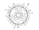
フレキシブルフライホイールの正面図。
図1における一部拡大図。
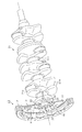
クランクシャフトにフレキシブルフライホイールが取り付けられた状態を示す斜視図。
フレキシブルフライホイールの別例を示す正面図。
フレキシブルフライホイールの別例を示す正面図。
フレキシブルフライホイールの別例を示す正面図。
フレキシブルフライホイールの別例を示す正面図。
The above objectives and other objectives, features and advantages of the present disclosure will be clarified by the following detailed description with reference to the accompanying drawings.
Front view of the flexible flywheel. Partially enlarged view in FIG. A perspective view showing a state in which a flexible flywheel is attached to a crankshaft. The front view which shows another example of a flexible flywheel. The front view which shows another example of a flexible flywheel. The front view which shows another example of a flexible flywheel. The front view which shows another example of a flexible flywheel.
以下、本開示を具体化した一実施の形態について、図面を参照しながら説明する。本実施の形態は、回転機として車両の内燃機関(エンジン)を想定し、エンジンが有するクランクシャフトに取り付けられるフレキシブルフライホイールについて説明する。
Hereinafter, an embodiment embodying the present disclosure will be described with reference to the drawings. In this embodiment, an internal combustion engine (engine) of a vehicle is assumed as a rotating machine, and a flexible flywheel attached to a crankshaft of the engine will be described.
図1に示すように、フレキシブルフライホイール10は全体として円形状をなしている。フレキシブルフライホイール10は、シャフト締結部11と、イナーシャリング12と、弾性スポーク部13と、重り部14とを有している。シャフト締結部11、イナーシャリング12、弾性スポーク部13及び重り部14は、鋳鉄等よりなる鋳物であり、鋳造によって一体形成されている。
As shown in FIG. 1, the flexible flywheel 10 has a circular shape as a whole. The flexible flywheel 10 has a shaft fastening portion 11, an inertia ring 12, an elastic spoke portion 13, and a weight portion 14. The shaft fastening portion 11, the inertia ring 12, the elastic spoke portion 13, and the weight portion 14 are castings made of cast iron or the like, and are integrally formed by casting.
シャフト締結部11は、図3に示すように、クランクシャフト21の先端部に締結される。図1に示すように、シャフト締結部11は円板状に形成され、フレキシブルフライホイール10の中央部に設けられている。図3に示すように、シャフト締結部11は、クランクシャフト21への取り付け時において、クランクシャフト21の端部に設けられた被締結部22の端面23と当接する。
As shown in FIG. 3, the shaft fastening portion 11 is fastened to the tip end portion of the crankshaft 21. As shown in FIG. 1, the shaft fastening portion 11 is formed in a disk shape and is provided in the central portion of the flexible flywheel 10. As shown in FIG. 3, the shaft fastening portion 11 comes into contact with the end surface 23 of the fastened portion 22 provided at the end portion of the crankshaft 21 when the shaft fastening portion 11 is attached to the crankshaft 21.
図1に示すように、シャフト締結部11の中央部には、位置決め孔31が設けられている。シャフト締結部11がクランクシャフト21の被締結部22の端面23と当接すると、図3に示すように、当該端面23に設けられた先端突部24が位置決め孔31に挿入される。これにより、クランクシャフト21の回転中心軸線とフレキシブルフライホイール10の回転中心軸線とが同一となるように位置決めされる。
As shown in FIG. 1, a positioning hole 31 is provided in the central portion of the shaft fastening portion 11. When the shaft fastening portion 11 comes into contact with the end surface 23 of the fastened portion 22 of the crankshaft 21, the tip protrusion 24 provided on the end surface 23 is inserted into the positioning hole 31 as shown in FIG. As a result, the rotation center axis of the crankshaft 21 and the rotation center axis of the flexible flywheel 10 are positioned to be the same.
図1に示すように、位置決め孔31の周囲には、複数のボルト挿通孔32が環状をなすように設けられている。図3に示すように、ボルト挿通孔32に対応するボルト孔25が、クランクシャフト21の被締結部22に設けられている。クランクシャフト21の先端突部24が位置決め孔31に挿入された状態で、ボルト挿通孔32とボルト孔25の位置を合わせる。ボルト孔25にボルト26をねじ込むことにより、シャフト締結部11が被締結部22に締結される。これにより、フレキシブルフライホイール10がクランクシャフト21に固定される。
As shown in FIG. 1, a plurality of bolt insertion holes 32 are provided around the positioning hole 31 so as to form an annular shape. As shown in FIG. 3, a bolt hole 25 corresponding to the bolt insertion hole 32 is provided in the fastened portion 22 of the crankshaft 21. With the tip protrusion 24 of the crankshaft 21 inserted into the positioning hole 31, the positions of the bolt insertion hole 32 and the bolt hole 25 are aligned. By screwing the bolt 26 into the bolt hole 25, the shaft fastening portion 11 is fastened to the fastened portion 22. As a result, the flexible flywheel 10 is fixed to the crankshaft 21.
図1に示すように、イナーシャリング12は円環状に形成されている。フレキシブルフライホイール10が回転すると、イナーシャリング12が慣性マスとなり、その重量によって比較的大きな慣性力モーメントが得られる。イナーシャリング12には、ネジ孔33が形成されている。ネジ孔33を利用して、ダンパー(図示略)が取り付けられる。なお、ダンパーの有無は任意である。
As shown in FIG. 1, the inertia ring 12 is formed in an annular shape. When the flexible flywheel 10 rotates, the inertia ring 12 becomes an inertial mass, and a relatively large inertial force moment is obtained by its weight. A screw hole 33 is formed in the inertia ring 12. A damper (not shown) is attached using the screw hole 33. The presence or absence of a damper is optional.
弾性スポーク部13は、シャフト締結部11とイナーシャリング12との間で、フレキシブルフライホイール10の径方向に沿って延び、両者を連結している。図2に示すように、弾性スポーク部13は幅広に形成されている。弾性スポーク部13において、イナーシャリング12との外側連結部34における側縁34aは、内側へ凹となるアール形状をなすように形成されている。
The elastic spoke portion 13 extends along the radial direction of the flexible flywheel 10 between the shaft fastening portion 11 and the inertia ring 12 and connects the two. As shown in FIG. 2, the elastic spoke portion 13 is formed to be wide. In the elastic spoke portion 13, the side edge 34a of the outer connecting portion 34 with the inertia ring 12 is formed so as to form a radius shape that is concave inward.
図3に示すように、弾性スポーク部13は、シャフト締結部11よりも薄肉に形成されている。弾性スポーク部13の撓みによって振動減衰効果が得られ、フライホイールがフレキシブル化される。弾性スポーク部13の厚みは任意であるが、例えば2mm~5mmの寸法に設定されている。そのため、振動減衰効果を得ることを目的としないフライホイールのプレート部と比較して、弾性スポーク部13の面剛性が下げられ、撓みやすくなっている。
As shown in FIG. 3, the elastic spoke portion 13 is formed to be thinner than the shaft fastening portion 11. The vibration damping effect is obtained by the bending of the elastic spoke portion 13, and the flywheel is made flexible. The thickness of the elastic spoke portion 13 is arbitrary, but is set to, for example, 2 mm to 5 mm. Therefore, the surface rigidity of the elastic spoke portion 13 is lowered as compared with the plate portion of the flywheel which is not intended to obtain the vibration damping effect, and the elastic spoke portion 13 is easily bent.
図1に示すように、弾性スポーク部13は3つ設けられ、いずれも同じ構成を有している。3本の弾性スポーク部13は、フレキシブルフライホイール10の周方向に均等に配置されている。正面視において、各弾性スポーク部13の幅方向の中央とフレキシブルフライホイール10の中心とを結ぶ各仮想線L1~L3を想定する。この場合、仮想線L1~L3同士の間の角度は120度に設定されている。弾性スポーク部13同士の間には、3つの空間部15が形成されている。
As shown in FIG. 1, three elastic spoke portions 13 are provided, and all have the same configuration. The three elastic spoke portions 13 are evenly arranged in the circumferential direction of the flexible flywheel 10. In front view, it is assumed that the virtual lines L1 to L3 connecting the center of each elastic spoke portion 13 in the width direction and the center of the flexible flywheel 10 are assumed. In this case, the angle between the virtual lines L1 to L3 is set to 120 degrees. Three space portions 15 are formed between the elastic spoke portions 13.
弾性スポーク部13には、2つの長孔35が形成されている。各長孔35は貫通孔であり、いずれも同じ形状かつ同一寸法で形成されている。長孔35は、弾性スポーク部13が延びる方向に沿って延びている。長孔35の長手方向両端部のうち、シャフト締結部11の側の一端部は、シャフト締結部11の近傍に配置され、イナーシャリング12の側の他端部は、イナーシャリング12の近傍に配置されている。図2に示すように、それら両端部における内縁36は、いずれもアール形状をなすように形成されている。
Two elongated holes 35 are formed in the elastic spoke portion 13. Each elongated hole 35 is a through hole, and all are formed with the same shape and the same dimensions. The elongated hole 35 extends along the direction in which the elastic spoke portion 13 extends. Of both ends in the longitudinal direction of the elongated hole 35, one end on the shaft fastening portion 11 side is arranged near the shaft fastening portion 11, and the other end on the inertia ring 12 side is arranged near the inertia ring 12. Has been done. As shown in FIG. 2, the inner edges 36 at both ends thereof are all formed in a rounded shape.
図2に示すように、弾性スポーク部13には2つの長孔35が形成されているため、弾性スポーク部13は3本の細スポーク部13a~13cに分けられている。各細スポーク部13a~13cのうち中央の細スポーク部13bは、弾性スポーク部13の左右中央を通る前述の各仮想線L1~L3の線上に設けられ、弾性スポーク部13が延びる方向と同じ方向に沿って延びている。両側の細スポーク部13a,13cは、中央の細スポーク部13bと平行に並んで設けられている。
As shown in FIG. 2, since the elastic spoke portions 13 are formed with two elongated holes 35, the elastic spoke portions 13 are divided into three fine spoke portions 13a to 13c. The central thin spoke portions 13b of the fine spoke portions 13a to 13c are provided on the above-mentioned virtual lines L1 to L3 passing through the left and right centers of the elastic spoke portions 13, and are in the same direction as the direction in which the elastic spoke portions 13 extend. Extends along. The thin spoke portions 13a and 13c on both sides are provided side by side in parallel with the central thin spoke portions 13b.
図1に示すように、重り部14は、各弾性スポーク部13の間に設けられた3つの空間部15のすべてに設けられている。各空間部15にはそれぞれ1つずつ重り部14が設けられ、各重り部14はいずれも同じ構成を有している。重り部14は、シャフト締結部11に連結されている。一方で、重り部14はイナーシャリング12と非連結であり、当該イナーシャリング12から離間して設けられている。重り部14のシャフト締結部11を挟んだ反対側には、弾性スポーク部13が設けられている。重り部14は、中央の細スポーク部13bの延長線上に設けられている。
As shown in FIG. 1, the weight portions 14 are provided in all of the three space portions 15 provided between the elastic spoke portions 13. One weight portion 14 is provided in each space portion 15, and each of the weight portions 14 has the same configuration. The weight portion 14 is connected to the shaft fastening portion 11. On the other hand, the weight portion 14 is not connected to the inertia ring 12, and is provided apart from the inertia ring 12. An elastic spoke portion 13 is provided on the opposite side of the weight portion 14 with the shaft fastening portion 11 interposed therebetween. The weight portion 14 is provided on an extension line of the central thin spoke portion 13b.
図1及び図3に示すように、重り部14は、平板状をなすように形成され、弾性スポーク部13と同じ板厚を有している。また、図1に示すように、重り部14は、正面視において、イナーシャリング12の周方向に沿って幅広に形成されている。重り部14は、弾性スポーク部13の中央を通る前述の各仮想線L1~L3を延長した延長線を基準として、線対称をなしている。重り部14は、周方向の広い範囲でシャフト締結部11と連結されている。
As shown in FIGS. 1 and 3, the weight portion 14 is formed in a flat plate shape and has the same plate thickness as the elastic spoke portions 13. Further, as shown in FIG. 1, the weight portion 14 is formed to be wide along the circumferential direction of the inertia ring 12 in the front view. The weight portion 14 has line symmetry with respect to an extension line extending from each of the above-mentioned virtual lines L1 to L3 passing through the center of the elastic spoke portion 13. The weight portion 14 is connected to the shaft fastening portion 11 in a wide range in the circumferential direction.
図2に示すように、重り部14の外縁37は、イナーシャリング12と同じ曲率の円弧状をなすように形成されている。重り部14における周方向両側の側縁部38は、S字形状をなすように形成されている。重り部14のシャフト締結部11との連結部である重り連結部41と、弾性スポーク部13のシャフト締結部11との連結部である内側連結部42とは、つなぎ部43によってつながっている。つなぎ部43は、シャフト締結部11の中心に向かって凹となるアール形状をなすように形成されている。つなぎ部43の外縁部分は、重り連結部41の周方向両側の側縁であり、内側連結部42の周方向両側の側縁でもある。
As shown in FIG. 2, the outer edge 37 of the weight portion 14 is formed so as to form an arc shape having the same curvature as the inertia ring 12. The side edge portions 38 on both sides of the weight portion 14 in the circumferential direction are formed so as to form an S shape. The weight connecting portion 41, which is a connecting portion of the weight portion 14 to the shaft fastening portion 11, and the inner connecting portion 42, which is a connecting portion of the elastic spoke portion 13 to the shaft fastening portion 11, are connected by a connecting portion 43. The connecting portion 43 is formed so as to form a radius shape that is concave toward the center of the shaft fastening portion 11. The outer edge portion of the connecting portion 43 is a side edge on both sides in the circumferential direction of the weight connecting portion 41, and is also a side edge on both sides in the circumferential direction of the inner connecting portion 42.
以上の構成を有するフレキシブルフライホイール10は、図3に示すように、クランクシャフト21の端部に連結される。図3は連結状態の一例を示している。フレキシブルフライホイール10に最も近い位置にあるクランクピン21aは、クランクアーム21bによって支持されている。クランクアーム21bがクランク軸21cから12時の方向へ突出する位置に配置された状態で、クランクアーム21bが延びる方向と弾性スポーク部13が延びる方向とが一致するように、フレキシブルフライホイール10がクランクシャフト21に取り付けられている。クランクアーム21bが12時の位置から回転し始める時点の爆発振動が最も大きく、フレキシブルフライホイール10がその影響を受けることが想定される。そこで、前述した連結状態が採用されている。シャフト締結部11のボルト挿通孔32や被締結部22のボルト孔25は、このような取り付けが可能となるように配置されている。
The flexible flywheel 10 having the above configuration is connected to the end of the crankshaft 21 as shown in FIG. FIG. 3 shows an example of the connected state. The crank pin 21a located closest to the flexible flywheel 10 is supported by the crank arm 21b. The flexible flywheel 10 cranks so that the direction in which the crank arm 21b extends and the direction in which the elastic spokes 13 extend coincide with each other in a state where the crank arm 21b protrudes from the crankshaft 21c in the 12 o'clock direction. It is attached to the shaft 21. It is assumed that the explosive vibration at the time when the crank arm 21b starts to rotate from the 12 o'clock position is the largest, and the flexible flywheel 10 is affected by this. Therefore, the above-mentioned connected state is adopted. The bolt insertion hole 32 of the shaft fastening portion 11 and the bolt hole 25 of the fastened portion 22 are arranged so as to enable such attachment.
なお、クランクシャフト21とフレキシブルフライホイール10との連結状態を、変更してもよい。エンジンの中には、12時の位置とは異なる位置からクランクアーム21bが回転し始める時点で、最も大きな爆発振動が生じるものもある。その角度のずれに弾性スポーク部13が延びる方向を合わせて、例えば10時や2時の位置となるように、フレキシブルフライホイール10がクランクシャフト21に取り付けられた構成としてもよい。
The connection state between the crankshaft 21 and the flexible flywheel 10 may be changed. In some engines, the largest explosive vibration occurs when the crank arm 21b starts to rotate from a position different from the 12 o'clock position. The flexible flywheel 10 may be attached to the crankshaft 21 so that the direction in which the elastic spoke portion 13 extends is aligned with the deviation of the angle so that the position is, for example, 10 o'clock or 2 o'clock.
次に、上記のフレキシブルフライホイール10を用いた場合の作用について説明する。
Next, the operation when the above flexible flywheel 10 is used will be described.
クランクシャフト21が回転すると、イナーシャリング12によって慣性モーメントが生じ、それによりクランクシャフト21の安定した回転動作が得られる。エンジンの駆動に起因してクランクシャフト21が振動すると、その振動はフレキシブルフライホイール10のシャフト締結部11に伝わる。それがさらに弾性スポーク部13に伝わると、弾性スポーク部13が弾性変形し、その振動を吸収して低減させる。これにより、クランクシャフト21は振動が抑制されて安定して回転動作することができる。
When the crankshaft 21 rotates, an inertial moment is generated by the inertia ring 12, and a stable rotational operation of the crankshaft 21 can be obtained. When the crankshaft 21 vibrates due to the driving of the engine, the vibration is transmitted to the shaft fastening portion 11 of the flexible flywheel 10. When it is further transmitted to the elastic spoke portion 13, the elastic spoke portion 13 is elastically deformed, and the vibration is absorbed and reduced. As a result, the crankshaft 21 can be stably rotated while vibration is suppressed.
フレキシブルフライホイール10は、クランクアーム21bが12時の位置に配置された場合に、それと同じ方向に沿って弾性スポーク部13が延びるように、クランクシャフト21に取り付けられている。本実施形態の想定では、当該クランクアーム21bはこの位置から回転し始める時点で、フレキシブルフライホイール10に最も大きな振動を与える。クランクアーム21bからの爆発振動は、空間部15ではなく剛性を備えた弾性スポーク部13で受け止められ、当該弾性スポーク部13によって振動が吸収される。これにより、クランクシャフト21から作用する振動の中でも大きな振動である爆発振動について、振動減衰の効果が高まる。
The flexible flywheel 10 is attached to the crankshaft 21 so that when the crank arm 21b is arranged at the 12 o'clock position, the elastic spoke portion 13 extends along the same direction. In the assumption of the present embodiment, the crank arm 21b gives the largest vibration to the flexible flywheel 10 when it starts to rotate from this position. The explosive vibration from the crank arm 21b is received by the elastic spoke portion 13 having rigidity instead of the space portion 15, and the vibration is absorbed by the elastic spoke portion 13. As a result, the effect of vibration damping is enhanced with respect to the explosive vibration, which is a large vibration among the vibrations acting from the crankshaft 21.
それに加え、各弾性スポーク部13が延びる方向において、個々の弾性スポーク部13のシャフト締結部11を挟んだ反対側には重り部14が設けられている。クランクシャフト21が振動すると、その振動によって重り部14が振られるため、重り部14の振れによってもクランクシャフト21の振動を吸収することができる。これにより、クランクシャフト21を挟んだ両側で、弾性スポーク部13と重り部14とによってクランクシャフト21の振動が吸収される。
In addition, a weight portion 14 is provided on the opposite side of each elastic spoke portion 13 across the shaft fastening portion 11 in the direction in which each elastic spoke portion 13 extends. When the crankshaft 21 vibrates, the weight portion 14 is shaken by the vibration, so that the vibration of the crankshaft 21 can be absorbed even by the vibration of the weight portion 14. As a result, the vibration of the crankshaft 21 is absorbed by the elastic spoke portions 13 and the weight portions 14 on both sides of the crankshaft 21.
以上をまとめると、本実施の形態のフレキシブルフライホイール10によれば、以下の作用効果を奏することができる。
Summarizing the above, according to the flexible flywheel 10 of the present embodiment, the following actions and effects can be achieved.
(1)フレキシブルフライホイール10が有する弾性スポーク部13は、薄肉に形成されており、面剛性が下げられて撓みやすく形成されている。クランクシャフト21に振動が生じると、その振動は弾性スポーク部13の撓みによって吸収される。これにより、クランクシャフト21の振動を減衰させることができる。従前のフレキシブルフライホイールでは、弾性円板がイナーシャリングとは別部品とされ、両者が締結されていた。それとは異なり、弾性スポーク部13は、シャフト締結部11及びイナーシャリング12とともに鋳造によって一体成形されている。そのため、部品点数は1点となり、複数の部品を一体化するための締結作業が不要となる。これにより、振動減衰機能を維持しながら、製造コストを低減することができる。
(1) The elastic spoke portion 13 of the flexible flywheel 10 is formed to be thin, and the surface rigidity is lowered so that the flexible flywheel 10 is easily bent. When vibration is generated in the crankshaft 21, the vibration is absorbed by the bending of the elastic spoke portion 13. As a result, the vibration of the crankshaft 21 can be damped. In the conventional flexible flywheel, the elastic disk is a separate part from the inertia ring, and both are fastened. On the other hand, the elastic spoke portion 13 is integrally formed by casting together with the shaft fastening portion 11 and the inertia ring 12. Therefore, the number of parts is one, and the fastening work for integrating a plurality of parts becomes unnecessary. As a result, the manufacturing cost can be reduced while maintaining the vibration damping function.
(2)弾性スポーク部13は3本設けられ、各弾性スポーク部13の間の空間部15には、シャフト締結部11に連結された重り部14が設けられている。クランクシャフト21が振動すると、その振動によって重り部14が振られる。その重り部14の振れによってクランクシャフト21の振動を吸収することができる。弾性スポーク部13と重り部14との両者によってクランクシャフト21の振動が吸収されるため、振動をより一層減衰させることができる。
(2) Three elastic spoke portions 13 are provided, and a weight portion 14 connected to the shaft fastening portion 11 is provided in the space portion 15 between the elastic spoke portions 13. When the crankshaft 21 vibrates, the weight portion 14 is shaken by the vibration. The vibration of the crankshaft 21 can be absorbed by the vibration of the weight portion 14. Since the vibration of the crankshaft 21 is absorbed by both the elastic spoke portion 13 and the weight portion 14, the vibration can be further damped.
重り部14も、シャフト締結部11等とともに鋳造によって一体成形されている。そのため、重り部14の存在によって部品点数が増加したり、新たな締結作業が発生したりすることはない。これにより、部品点数や作業工程を増加させずに、製造コストを低減させつつ振動減衰効果を高めることができる。
The weight portion 14 is also integrally molded by casting together with the shaft fastening portion 11 and the like. Therefore, the presence of the weight portion 14 does not increase the number of parts or require new fastening work. As a result, the vibration damping effect can be enhanced while reducing the manufacturing cost without increasing the number of parts and the work process.
しかも、本実施の形態では、各弾性スポーク部13の幅方向中央の仮想線L1~L3の延長線上に、重り部14がそれぞれ設けられている。そのため、仮想線L1~L3の線上において、各弾性スポーク部13と各重り部14との間にシャフト締結部11が設けられている。そのため、クランクシャフト21を挟んだ両側で振動吸収、抑制が行われることとなり、クランクシャフト21の振動を減衰させる効果を高めることができる。
Moreover, in the present embodiment, the weight portions 14 are provided on the extension lines of the virtual lines L1 to L3 at the center in the width direction of each elastic spoke portion 13. Therefore, a shaft fastening portion 11 is provided between each elastic spoke portion 13 and each weight portion 14 on the virtual lines L1 to L3. Therefore, vibration absorption and suppression are performed on both sides of the crankshaft 21, and the effect of attenuating the vibration of the crankshaft 21 can be enhanced.
(3)重り部14のシャフト締結部11との連結部である重り連結部41と、弾性スポーク部13のシャフト締結部11との連結部である内側連結部42とは、つなぎ部43によってつながれている。つなぎ部43は、アール形状を有している。弾性スポーク部13のイナーシャリング12との連結部である外側連結部34において、その周方向両側の側縁34aもアール形状をなしている。
(3) The weight connecting portion 41, which is a connecting portion of the weight portion 14 to the shaft fastening portion 11, and the inner connecting portion 42, which is a connecting portion of the elastic spoke portion 13 to the shaft fastening portion 11, are connected by a connecting portion 43. ing. The connecting portion 43 has a rounded shape. In the outer connecting portion 34 which is the connecting portion of the elastic spoke portion 13 to the inertia ring 12, the side edges 34a on both sides in the circumferential direction also have a rounded shape.
つなぎ部43がアール形状を有していることにより、重り連結部41の側縁はくびれている。このくびれにより、重り部14が振動しやすい。また、弾性スポーク部13や重り部14が振動吸収のために撓むと、つなぎ部43や外側連結部34には応力が集中する。そのため、フレキシブルフライホイール10の経年使用によって当該部分に亀裂発生のおそれが生じる。この点、つなぎ部43や外側連結部34の周方向両側の側縁部34aがアール形状に形成されていることにより、その応力集中が緩和されて当該部分での亀裂発生のおそれを低減できる。
Since the connecting portion 43 has a rounded shape, the side edge of the weight connecting portion 41 is constricted. Due to this constriction, the weight portion 14 tends to vibrate. Further, when the elastic spoke portion 13 and the weight portion 14 bend due to vibration absorption, stress is concentrated on the connecting portion 43 and the outer connecting portion 34. Therefore, there is a risk of cracks occurring in the portion due to the aged use of the flexible flywheel 10. In this respect, since the side edge portions 34a on both sides of the connecting portion 43 and the outer connecting portion 34 in the circumferential direction are formed in a rounded shape, the stress concentration is relaxed and the possibility of cracks occurring in the portion can be reduced.
(4)弾性スポーク部13にはその延びる方向に沿って延びる2つの長孔35が形成され、3本の細スポーク部13a~13cに分けられている。そのため、弾性スポーク部13は、円形の貫通孔が形成されたりそもそも長孔35が形成されなかったりする構成よりも軽量化され、面剛性もより下げられている。これにより、弾性スポーク部13がより撓みやすくなり、クランクシャフト21の振動を減衰させる効果が高められている。
(4) The elastic spoke portion 13 is formed with two elongated holes 35 extending along the extending direction thereof, and is divided into three fine spoke portions 13a to 13c. Therefore, the elastic spoke portion 13 is lighter than the configuration in which the circular through hole is formed or the elongated hole 35 is not formed in the first place, and the surface rigidity is further lowered. As a result, the elastic spoke portion 13 is more easily bent, and the effect of attenuating the vibration of the crankshaft 21 is enhanced.
その上、2つの長孔35において、弾性スポーク部13が延びる方向の両端部は、シャフト締結部11及びイナーシャリング12の近傍にそれぞれ配置されている。両端部における内縁36は、アール形状をなすように形成されている。そのため、弾性スポーク部13の内側連結部42及び外側連結部34のそれぞれの内側に、アール形状を有する箇所が複数設けられている。これにより、当該アール形状を有する箇所が設けられない構成と比較して、弾性スポーク部13が撓む際にそれら連結部34,42に作用する応力を緩和させることができる。
Moreover, in the two elongated holes 35, both ends in the direction in which the elastic spoke portions 13 extend are arranged in the vicinity of the shaft fastening portion 11 and the inertia ring 12, respectively. The inner edges 36 at both ends are formed so as to form a radius. Therefore, a plurality of portions having a rounded shape are provided inside each of the inner connecting portion 42 and the outer connecting portion 34 of the elastic spoke portion 13. As a result, the stress acting on the connecting portions 34 and 42 when the elastic spoke portions 13 are bent can be relaxed as compared with the configuration in which the portion having the rounded shape is not provided.
なお、本発明は、上記実施形態のフレキシブルフライホイール10に限らず、例えば次のような構成を採用してもよい。
The present invention is not limited to the flexible flywheel 10 of the above embodiment, and for example, the following configuration may be adopted.
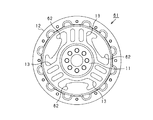
(a)上記実施の形態では、弾性スポーク部13は3本設けられている。これに代えて、図4に示すフレキシブルフライホイール52のように、弾性スポーク部53の数を4本としてもよい。弾性スポーク部13,53が設けられる本数は任意である。
(A) In the above embodiment, three elastic spoke portions 13 are provided. Instead of this, the number of elastic spoke portions 53 may be four as in the flexible flywheel 52 shown in FIG. The number of elastic spoke portions 13 and 53 provided is arbitrary.
(b)上記実施の形態では、各弾性スポーク部13の幅方向中央の延長線上(仮想線L1~L3の延長線上)に、重り部14が設けられている。これに代えて、図4に示すフレキシブルフライホイール52のように、弾性スポーク部53の幅方向中央の延長線上からずれた位置に重り部14が設けられた構成を採用してもよい。
(B) In the above embodiment, the weight portion 14 is provided on the extension line at the center of each elastic spoke portion 13 in the width direction (on the extension line of the virtual lines L1 to L3). Instead of this, a configuration in which the weight portion 14 is provided at a position deviated from the extension line at the center in the width direction of the elastic spoke portion 53 may be adopted as in the flexible flywheel 52 shown in FIG.
幅方向中央の延長線上からずれた位置に重り部14が配置された場合は、図4に示すように、弾性スポーク部53の周方向両側に重り部14が設けられ、その両側の重り部14は、弾性スポーク部53の幅方向中央を通る仮想線L4に対して線対称であってかつ同一形状を有することが好ましい。これにより、上記実施の形態と同じく、クランクシャフト21に生じる振動を左右均等に吸収して振動をバランスよく減衰できる。
When the weight portions 14 are arranged at positions deviated from the extension line at the center in the width direction, the weight portions 14 are provided on both sides of the elastic spoke portions 53 in the circumferential direction as shown in FIG. 4, and the weight portions 14 on both sides thereof are provided. Is line-symmetrical with respect to the virtual line L4 passing through the center of the elastic spoke portion 53 in the width direction, and preferably has the same shape. As a result, as in the above embodiment, the vibration generated in the crankshaft 21 can be absorbed evenly on the left and right, and the vibration can be attenuated in a well-balanced manner.
(c)上記実施の形態では、弾性スポーク部13同士の間の各空間部15には、それぞれ1つの重り部14が設けられている。これに代えて、各空間部15に複数の重り部14が設けられたり、空間部15ごとで異なる数の重り部14が設けられたりしてもよい。仮に、一つの空間部15に複数の重り部14が設けられる場合には、弾性スポーク部13が延びる仮想線L1~L3の延長線に対して線対称をなすように複数の重り部14が配置されることが好ましい。この構成であっても、上記実施の形態と同じ効果を得ることができる。
(C) In the above embodiment, one weight portion 14 is provided in each space portion 15 between the elastic spoke portions 13. Instead of this, a plurality of weight portions 14 may be provided in each space portion 15, or a different number of weight portions 14 may be provided in each space portion 15. If a plurality of weight portions 14 are provided in one space portion 15, the plurality of weight portions 14 are arranged so as to be line-symmetric with respect to the extension lines of the virtual lines L1 to L3 on which the elastic spoke portions 13 extend. It is preferable to be done. Even with this configuration, the same effect as that of the above embodiment can be obtained.
(d)上記実施の形態では、重り部14の厚みは弾性スポーク部13の厚みと同じである。これに代えて、重り部14の厚みを弾性スポーク部13の厚みよりも厚く形成してもよい。また、3つの重り部14を形状、大きさ、重さ等が同じものとするのではなく、図5に示すフレキシブルフライホイール54のように、形状、大きさ、重さ等が異なる重り部55a~55cが設けられてもよい。このように重り部55の重さ等を調整することにより、取付け対象となるクランクシャフト21の振動特性に合わせた最適な振動減衰効果が得られるように、フレキシブルフライホイール54の固有振動数(共振周波数)を調整することができる。
(D) In the above embodiment, the thickness of the weight portion 14 is the same as the thickness of the elastic spoke portion 13. Instead of this, the thickness of the weight portion 14 may be formed to be thicker than the thickness of the elastic spoke portion 13. Further, the three weight portions 14 do not have the same shape, size, weight, etc., but the weight portions 55a having different shapes, sizes, weights, etc., as in the flexible flywheel 54 shown in FIG. ~ 55c may be provided. By adjusting the weight of the weight portion 55 in this way, the natural frequency (resonance) of the flexible flywheel 54 can be obtained so that the optimum vibration damping effect according to the vibration characteristics of the crankshaft 21 to be attached can be obtained. Frequency) can be adjusted.
(e)上記実施の形態では、弾性スポーク部13に長孔35が形成されている。これに代えて、図4に示す弾性スポーク部53のように、長孔35が設けられない構成としてもよい。また、長孔35ではなく、円形状や楕円形状等の1つ又は複数の貫通孔としたり、図6に示すように涙滴形状の貫通孔57としたり、長孔35と他の形状の貫通孔とを組み合わせたりしてもよい。長孔35を形成するとしても、上記実施の形態のように、弾性スポーク部13が延びる方向に沿って延びるものではなく、当該方向と交差する方向に延びるように形成してもよい。
(E) In the above embodiment, the elongated holes 35 are formed in the elastic spoke portions 13. Instead of this, as in the elastic spoke portion 53 shown in FIG. 4, the elongated hole 35 may not be provided. Further, instead of the elongated hole 35, one or a plurality of through holes having a circular shape or an elliptical shape may be formed, or a teardrop-shaped through hole 57 may be formed as shown in FIG. 6, or the elongated hole 35 and another shape may be penetrated. It may be combined with a hole. Even if the elongated hole 35 is formed, it may be formed so as to extend in a direction intersecting the direction in which the elastic spoke portion 13 does not extend in the extending direction as in the above embodiment.
その他、弾性スポーク部13に形成される長孔35の個数は任意であり、例えば、1個の長孔35を形成したり、3個以上の長孔35を形成したりしてもよい。長孔35の長軸又は短軸方向の寸法も任意であり、例えば、本実施形態における図1の長孔35と比較して、短軸方法の寸法をより長くしたり、長軸方向の寸法をより短くしたりしてもよい。
In addition, the number of elongated holes 35 formed in the elastic spoke portion 13 is arbitrary, and for example, one elongated hole 35 may be formed, or three or more elongated holes 35 may be formed. The dimensions of the long hole 35 in the long axis or the short axis direction are also arbitrary. For example, the dimensions of the short axis method may be longer or the dimensions in the long axis direction as compared with the long hole 35 of FIG. 1 in this embodiment. May be shorter.
(f)上記実施の形態では、弾性スポーク部13に2つの長孔35が形成されることにより、3本の細スポーク部13a~13cに分けられている。それら各細スポーク部13a~13cは、いずれも弾性スポーク部13が延びる径方向に沿って延びている。これに代えて、図6に示すフレキシブルフライホイール56のように、弾性スポーク部58の細スポーク部58a~58cが放射状をなすように形成されてもよい。なお、図6では、放射状に延びる細スポーク部58a~58cは3本設けられているが、その本数は任意である。
(F) In the above embodiment, the elastic spoke portions 13 are divided into three fine spoke portions 13a to 13c by forming two elongated holes 35. Each of the fine spoke portions 13a to 13c extends along the radial direction in which the elastic spoke portions 13 extend. Instead of this, as in the flexible flywheel 56 shown in FIG. 6, the fine spoke portions 58a to 58c of the elastic spoke portions 58 may be formed so as to form a radial pattern. In FIG. 6, three thin spoke portions 58a to 58c extending radially are provided, but the number thereof is arbitrary.
(g)上記実施の形態では、重り部14がシャフト締結部11に連結され、イナーシャリング12とは非連結で、当該イナーシャリング12から離間して設けられている。これとは逆に、図7に示すフレキシブルフライホイール61のように、重り部62がイナーシャリング12に連結され、シャフト締結部11とは非連結で、当該シャフト締結部11から離間して設けられるようにしてもよい。この場合でも、重り部62のシャフト締結部11の側の縁部は円弧状をなすように形成され、周方向両端の側縁部はS字形状をなすように形成されている。この構成でも、上記実施の形態と同様に、クランクシャフト21の振動時において、重り部62の振れによってその振動を吸収することができる。
(G) In the above embodiment, the weight portion 14 is connected to the shaft fastening portion 11, is not connected to the inertia ring 12, and is provided apart from the inertia ring 12. On the contrary, like the flexible flywheel 61 shown in FIG. 7, the weight portion 62 is connected to the inertia ring 12, is not connected to the shaft fastening portion 11, and is provided apart from the shaft fastening portion 11. You may do so. Even in this case, the edge portion of the weight portion 62 on the side of the shaft fastening portion 11 is formed so as to form an arc shape, and the side edge portions at both ends in the circumferential direction are formed so as to form an S shape. Also in this configuration, when the crankshaft 21 vibrates, the vibration can be absorbed by the vibration of the weight portion 62, as in the above embodiment.
(h)上記実施の形態では、シャフト締結部11、イナーシャリング12、弾性スポーク部13及び重り部14が鋳造によって一体成形されている。これに代えて、これらの要素すべてが鍛造によって一体成形されたフレキシブルフライホイールとしてもよい。この構成でも、上記実施形態と同じ効果を得ることができる。
(H) In the above embodiment, the shaft fastening portion 11, the inertia ring 12, the elastic spoke portion 13, and the weight portion 14 are integrally molded by casting. Alternatively, a flexible flywheel in which all of these elements are integrally molded by forging may be used. Even with this configuration, the same effect as that of the above embodiment can be obtained.
(i)上記実施の形態では、回転機として車両の内燃機関(エンジン)を想定した。本開示の適用対象はそれに限定されるものではない。慣性モーメントを利用した回転の安定化や回転エネルギの保存等を図る目的で用いられるのであれば、例えばプレス機械に用いられるフライホイールなどに適用してもよい。
(I) In the above embodiment, an internal combustion engine (engine) of a vehicle is assumed as a rotating machine. The scope of this disclosure is not limited to that. If it is used for the purpose of stabilizing the rotation using the moment of inertia, preserving the rotational energy, etc., it may be applied to, for example, a flywheel used in a press machine.
本開示は、実施形態に準拠して記述されたが、本開示は当該実施形態や構造に限定されるものではないと理解される。本開示は、様々な変形例や均等範囲内の変形をも包含する。加えて、様々な組み合わせや形態、さらには、それらに一要素のみ、それ以上、あるいはそれ以下、を含む他の組み合わせや形態をも、本開示の範疇や思想範囲に入るものである。
Although the present disclosure has been described in accordance with an embodiment, it is understood that the present disclosure is not limited to the embodiment or structure. The present disclosure also includes various modifications and modifications within an equal range. In addition, various combinations and forms, as well as other combinations and forms that include only one element, more, or less, are also within the scope of the present disclosure.
10…フレキシブルフライホイール、11…シャフト締結部、12…イナーシャリング、13…弾性スポーク部、14…重り部、34…外側連結部、34a…側縁、35…長孔(貫通孔)、41…重り連結部、42…内側連結部、43…つなぎ部。
10 ... Flexible flywheel, 11 ... Shaft fastening part, 12 ... Inertia ring, 13 ... Elastic spoke part, 14 ... Weight part, 34 ... Outer connecting part, 34a ... Side edge, 35 ... Long hole (through hole), 41 ... Weight connecting part, 42 ... inner connecting part, 43 ... connecting part.
Claims (7)
- 回転機のシャフトの端部に固定されるシャフト締結部と、
前記シャフト締結部の周囲に設けられた円環状のイナーシャリングと、
前記シャフト締結部と前記イナーシャリングとの間で径方向に延びて両者を連結し、前記シャフトに作用する振動を自身の撓みによって吸収する複数の弾性スポーク部と、
前記弾性スポーク部同士の間に設けられるとともに、前記シャフト締結部及び前記イナーシャリングのうち一方に連結され他方から離間して設けられた重り部と、
を備え、
前記シャフト締結部、前記イナーシャリング、前記弾性スポーク部及び前記重り部が鋳造又は鍛造により一体成形されている、フレキシブルフライホイール。 A shaft fastening part fixed to the end of the shaft of the rotating machine,
An annular inertia ring provided around the shaft fastening portion and
A plurality of elastic spoke portions extending in the radial direction between the shaft fastening portion and the inertia ring to connect the two, and absorbing the vibration acting on the shaft by its own deflection.
A weight portion provided between the elastic spoke portions and connected to one of the shaft fastening portion and the inertia ring and provided apart from the other.
With
A flexible flywheel in which the shaft fastening portion, the inertia ring, the elastic spoke portion, and the weight portion are integrally molded by casting or forging. - 前記弾性スポーク部の幅方向中央を通る仮想線を想定し、
前記仮想線の延長線上に前記重り部が設けられ、
前記シャフト締結部は、前記弾性スポーク部と前記重り部との間に挟まれていることを特徴とする請求項1に記載のフレキシブルフライホイール。 Assuming a virtual line passing through the center of the elastic spoke portion in the width direction,
The weight portion is provided on the extension line of the virtual line.
The flexible flywheel according to claim 1, wherein the shaft fastening portion is sandwiched between the elastic spoke portion and the weight portion. - 前記弾性スポーク部を挟んだ周方向の両側に前記重り部が設けられ、当該両側の重り部は前記弾性スポーク部の幅方向中央を通る仮想線に対して線対称であってかつ同一形状を有している、請求項1に記載のフレキシブルフライホイール。 The weight portions are provided on both sides of the elastic spoke portion in the circumferential direction, and the weight portions on both sides are line-symmetrical and have the same shape with respect to the virtual line passing through the center in the width direction of the elastic spoke portion. The flexible flywheel according to claim 1.
- 前記弾性スポーク部の前記シャフト締結部との連結部における側縁と、前記弾性スポーク部の前記イナーシャリングとの連結部における側縁とのうち少なくとも一方がアール形状をなすように形成されている、請求項1乃至3のいずれか1項に記載のフレキシブルフライホイール。 At least one of the side edge of the elastic spoke portion at the connecting portion with the shaft fastening portion and the side edge of the elastic spoke portion at the connecting portion with the inertia ring are formed so as to form a radius shape. The flexible flywheel according to any one of claims 1 to 3.
- 前記重り部の前記シャフト締結部又は前記イナーシャリングとの連結部における側縁は、凹状をなすアール形状に形成されている、請求項1乃至4のいずれか1項に記載のフレキシブルフライホイール。 The flexible flywheel according to any one of claims 1 to 4, wherein the side edge of the weight portion at the shaft fastening portion or the connecting portion with the inertia ring is formed in a concave rounded shape.
- 前記弾性スポーク部には、当該弾性スポーク部を貫通する貫通孔が設けられている、請求項1乃至5のいずれか1項に記載のフレキシブルフライホイール。 The flexible flywheel according to any one of claims 1 to 5, wherein the elastic spoke portion is provided with a through hole penetrating the elastic spoke portion.
- 前記貫通孔は、前記弾性スポーク部が延びる方向に沿って延びる長孔であり、
前記長孔において前記方向の一端部は前記シャフト締結部の近傍に配置され、他端部は前記イナーシャリングの近傍に配置され、
前記一端部及び前記他端部のうち少なくとも一方の内縁が、アール形状をなすように形成されている、請求項6に記載のフレキシブルフライホイール。 The through hole is an elongated hole extending along the direction in which the elastic spoke portion extends.
In the elongated hole, one end in the direction is arranged in the vicinity of the shaft fastening portion, and the other end is arranged in the vicinity of the inertia ring.
The flexible flywheel according to claim 6, wherein at least one inner edge of the one end and the other end is formed so as to form a radius.
Priority Applications (4)
| Application Number | Priority Date | Filing Date | Title |
|---|---|---|---|
| CN202080016951.1A CN113490801B (en) | 2019-03-25 | 2020-03-11 | Flexible flywheel |
| JP2021509003A JP7060760B2 (en) | 2019-03-25 | 2020-03-11 | Flexible flywheel |
| US17/429,224 US11873879B2 (en) | 2019-03-25 | 2020-03-11 | Flexible flywheel |
| DE112020001446.0T DE112020001446T5 (en) | 2019-03-25 | 2020-03-11 | FLEXIBLE FLYWHEEL |
Applications Claiming Priority (2)
| Application Number | Priority Date | Filing Date | Title |
|---|---|---|---|
| JP2019-056923 | 2019-03-25 | ||
| JP2019056923 | 2019-03-25 |
Publications (1)
| Publication Number | Publication Date |
|---|---|
| WO2020195833A1 true WO2020195833A1 (en) | 2020-10-01 |
Family
ID=72611396
Family Applications (1)
| Application Number | Title | Priority Date | Filing Date |
|---|---|---|---|
| PCT/JP2020/010544 WO2020195833A1 (en) | 2019-03-25 | 2020-03-11 | Flexible flywheel |
Country Status (5)
| Country | Link |
|---|---|
| US (1) | US11873879B2 (en) |
| JP (1) | JP7060760B2 (en) |
| CN (1) | CN113490801B (en) |
| DE (1) | DE112020001446T5 (en) |
| WO (1) | WO2020195833A1 (en) |
Families Citing this family (2)
| Publication number | Priority date | Publication date | Assignee | Title |
|---|---|---|---|---|
| JP7101711B2 (en) * | 2020-02-19 | 2022-07-15 | アイシン高丘株式会社 | Flexible flywheel |
| DE102022104006A1 (en) * | 2022-02-21 | 2023-08-24 | Schaeffler Technologies AG & Co. KG | Vibration damper constructed from spoke spring absorbers |
Citations (6)
| Publication number | Priority date | Publication date | Assignee | Title |
|---|---|---|---|---|
| JPS54109584A (en) * | 1978-02-15 | 1979-08-28 | Agency Of Ind Science & Technol | Energy accumulating fly-wheel with spoke |
| JPS5758542B2 (en) * | 1976-09-07 | 1982-12-10 | Mitsubishi Motors Corp | |
| JPS60177350U (en) * | 1984-05-04 | 1985-11-25 | 日産自動車株式会社 | internal combustion engine flywheel |
| JPH0712646U (en) * | 1993-08-05 | 1995-03-03 | 本田技研工業株式会社 | Flexible flywheel |
| JPH11182631A (en) * | 1997-12-19 | 1999-07-06 | Daihatsu Motor Co Ltd | Flexible flywheel |
| JP2004074230A (en) * | 2002-08-19 | 2004-03-11 | Ricoh Co Ltd | Flywheel and its manufacturing method |
Family Cites Families (29)
| Publication number | Priority date | Publication date | Assignee | Title |
|---|---|---|---|---|
| US670388A (en) * | 1900-07-05 | 1901-03-19 | George H Howard | Fly-wheel. |
| AT239612B (en) | 1962-10-29 | 1965-04-12 | Geislinger Dr Ing Leonard | Vibration damper for torsional vibrations |
| US3387505A (en) | 1965-10-23 | 1968-06-11 | Houdaille Industries Inc | Tuned torsional vibration damper |
| US3462136A (en) | 1967-06-29 | 1969-08-19 | Houdaille Industries Inc | Tuned viscous vibration dampers |
| JPH09504597A (en) | 1994-08-20 | 1997-05-06 | オートモーティヴ・プロダクツ・パブリック・リミテッド・カンパニー | Two mass flywheel |
| JP3208016B2 (en) | 1994-08-30 | 2001-09-10 | 富士機工株式会社 | Vehicle drive plate |
| JP3160165B2 (en) * | 1994-09-30 | 2001-04-23 | 富士機工株式会社 | Vehicle drive plate |
| US6216327B1 (en) * | 1998-04-30 | 2001-04-17 | Simpson Industries, Inc. | Spoke centered puller tab crankshaft damper hub |
| US6440044B1 (en) * | 1998-08-07 | 2002-08-27 | Spiraflex, Inc. | Resistance mechanism with series connected resistance packs |
| JP3541716B2 (en) | 1999-03-11 | 2004-07-14 | 三菱自動車工業株式会社 | Flywheel device for internal combustion engine |
| KR200199530Y1 (en) | 2000-03-30 | 2000-10-02 | 정인관 | A fly wheel with balance weight in the center |
| FR2849683B1 (en) * | 2003-01-06 | 2006-07-28 | Valeo Embrayages | FLEXIBLE INERTILE WHEEL FOR TORQUE TRANSMISSION DEVICE |
| FR2880398B1 (en) | 2005-01-03 | 2007-02-16 | Valeo Embrayages | INERTIAL WHEEL FOR INTERNAL COMBUSTION ENGINE |
| FR2890716B1 (en) * | 2005-09-09 | 2007-12-07 | Valeo Embrayages | FLEXIBLE INERTIAL WHEEL, ESPECIALLY FOR A MOTOR VEHICLE |
| WO2009051800A1 (en) * | 2007-10-18 | 2009-04-23 | Kohler Co. | Flywheel assembly |
| FR2925638B1 (en) * | 2007-12-20 | 2012-12-21 | Renault Sas | INERTIA WHEEL FOR MOTOR VEHICLE WITH DAMPER GASKETS |
| DE102011017397A1 (en) | 2010-05-14 | 2011-11-17 | Schaeffler Technologies Gmbh & Co. Kg | Flywheel for use with drive train for increasing moment of inertia of crankshaft of internal combustion engine, comprises mass ring, which is provided radially outside, and mounting flange, which is provided radially inside |
| JP5728186B2 (en) * | 2010-09-13 | 2015-06-03 | アイシン機工株式会社 | Drive plate and ring gear member of drive plate |
| JP6265140B2 (en) | 2012-12-21 | 2018-01-24 | 株式会社リコー | Microlens array and moving body |
| WO2017035515A1 (en) | 2015-08-27 | 2017-03-02 | Dayco Ip Holdings, Llc | Torsional vibration dampers having a hub with spokes acting as a second spring in series with an elastomeric member |
| US20170102048A1 (en) * | 2015-10-13 | 2017-04-13 | Ford Global Technologies, Llc | High performance flexplate with alternating radial wall thickness and multi-profile lightening holes |
| DE102016207100A1 (en) | 2016-04-27 | 2017-11-02 | Schaeffler Technologies AG & Co. KG | vibration |
| CN109210144B (en) * | 2017-06-29 | 2022-12-09 | 南京法雷奥离合器有限公司 | Preloading part, preloading assembly, dual mass flywheel and motor vehicle |
| CN108050204A (en) * | 2018-01-06 | 2018-05-18 | 樊品良 | A kind of flywheel shaft coupling |
| CN108708934A (en) | 2018-08-01 | 2018-10-26 | 广西玉柴机器股份有限公司 | Two cylinder arbor system balance shock system |
| CN109083979A (en) | 2018-08-28 | 2018-12-25 | 中国北方发动机研究所(天津) | A kind of flexibility sectional flywheel |
| IT201800010483A1 (en) * | 2018-11-21 | 2020-05-21 | Scuola Superiore Di Studi Univ E Di Perfezionamento Santanna | PLANAR TORSION SPRING |
| DE102019101983B4 (en) | 2019-01-28 | 2022-11-17 | Schaeffler Technologies AG & Co. KG | Spoke spring absorber and use of a spoke spring absorber |
| JP7101711B2 (en) * | 2020-02-19 | 2022-07-15 | アイシン高丘株式会社 | Flexible flywheel |
-
2020
- 2020-03-11 US US17/429,224 patent/US11873879B2/en active Active
- 2020-03-11 JP JP2021509003A patent/JP7060760B2/en active Active
- 2020-03-11 WO PCT/JP2020/010544 patent/WO2020195833A1/en active Application Filing
- 2020-03-11 DE DE112020001446.0T patent/DE112020001446T5/en active Pending
- 2020-03-11 CN CN202080016951.1A patent/CN113490801B/en active Active
Patent Citations (6)
| Publication number | Priority date | Publication date | Assignee | Title |
|---|---|---|---|---|
| JPS5758542B2 (en) * | 1976-09-07 | 1982-12-10 | Mitsubishi Motors Corp | |
| JPS54109584A (en) * | 1978-02-15 | 1979-08-28 | Agency Of Ind Science & Technol | Energy accumulating fly-wheel with spoke |
| JPS60177350U (en) * | 1984-05-04 | 1985-11-25 | 日産自動車株式会社 | internal combustion engine flywheel |
| JPH0712646U (en) * | 1993-08-05 | 1995-03-03 | 本田技研工業株式会社 | Flexible flywheel |
| JPH11182631A (en) * | 1997-12-19 | 1999-07-06 | Daihatsu Motor Co Ltd | Flexible flywheel |
| JP2004074230A (en) * | 2002-08-19 | 2004-03-11 | Ricoh Co Ltd | Flywheel and its manufacturing method |
Also Published As
| Publication number | Publication date |
|---|---|
| CN113490801B (en) | 2022-12-20 |
| DE112020001446T5 (en) | 2021-12-02 |
| US20220010859A1 (en) | 2022-01-13 |
| CN113490801A (en) | 2021-10-08 |
| US11873879B2 (en) | 2024-01-16 |
| JP7060760B2 (en) | 2022-04-26 |
| JPWO2020195833A1 (en) | 2021-10-14 |
Similar Documents
| Publication | Publication Date | Title |
|---|---|---|
| US8813604B2 (en) | Pendulum vibration absorber on a crankshaft | |
| JP5068666B2 (en) | Inertial flywheel for internal combustion engines | |
| WO2020195833A1 (en) | Flexible flywheel | |
| JP6811702B2 (en) | Tortional damper | |
| CN108240416A (en) | Torsional vibration damper, flywheel and car transmissions | |
| US10113611B2 (en) | Torsional vibration damper and engine assembly including the same | |
| KR101087884B1 (en) | Flexible flywheel for torque transmission device | |
| WO2021166685A1 (en) | Flexible flywheel | |
| JP2008175344A (en) | Attaching structure of dynamic damper to rotating shaft, and rotary shaft with dynamic damper | |
| JP6650765B2 (en) | engine | |
| JPH0531311Y2 (en) | ||
| JP6707864B2 (en) | Vibration damping device | |
| JPS6338572B2 (en) | ||
| JP2006090528A (en) | Vibration control device for rotary shaft | |
| KR101868699B1 (en) | Pendulum assembly for dual mass flywheel | |
| JP3532612B2 (en) | Torsion damper | |
| JP7110829B2 (en) | dynamic damper | |
| JP7420456B2 (en) | internal combustion engine crankshaft | |
| JP2019148303A (en) | Dynamic damper | |
| JP7067381B2 (en) | Damper device | |
| JPH0640992Y2 (en) | Engine flywheel equipment | |
| JPH024269Y2 (en) | ||
| JP2002139103A (en) | Crank damper | |
| JP2002317647A (en) | Vibration restraining mechanism for internal combustion engine | |
| JP2021063533A (en) | Pulley damper |
Legal Events
| Date | Code | Title | Description |
|---|---|---|---|
| 121 | Ep: the epo has been informed by wipo that ep was designated in this application |
Ref document number: 20776618 Country of ref document: EP Kind code of ref document: A1 |
|
| ENP | Entry into the national phase |
Ref document number: 2021509003 Country of ref document: JP Kind code of ref document: A |
|
| 122 | Ep: pct application non-entry in european phase |
Ref document number: 20776618 Country of ref document: EP Kind code of ref document: A1 |