WO2020195422A1 - 電源装置 - Google Patents
電源装置 Download PDFInfo
- Publication number
- WO2020195422A1 WO2020195422A1 PCT/JP2020/007026 JP2020007026W WO2020195422A1 WO 2020195422 A1 WO2020195422 A1 WO 2020195422A1 JP 2020007026 W JP2020007026 W JP 2020007026W WO 2020195422 A1 WO2020195422 A1 WO 2020195422A1
- Authority
- WO
- WIPO (PCT)
- Prior art keywords
- power supply
- supply device
- voltage detection
- battery cell
- battery
- Prior art date
- Legal status (The legal status is an assumption and is not a legal conclusion. Google has not performed a legal analysis and makes no representation as to the accuracy of the status listed.)
- Ceased
Links
Images


Classifications
-
- H—ELECTRICITY
- H01—ELECTRIC ELEMENTS
- H01M—PROCESSES OR MEANS, e.g. BATTERIES, FOR THE DIRECT CONVERSION OF CHEMICAL ENERGY INTO ELECTRICAL ENERGY
- H01M50/00—Constructional details or processes of manufacture of the non-active parts of electrochemical cells other than fuel cells, e.g. hybrid cells
- H01M50/20—Mountings; Secondary casings or frames; Racks, modules or packs; Suspension devices; Shock absorbers; Transport or carrying devices; Holders
- H01M50/204—Racks, modules or packs for multiple batteries or multiple cells
- H01M50/207—Racks, modules or packs for multiple batteries or multiple cells characterised by their shape
- H01M50/213—Racks, modules or packs for multiple batteries or multiple cells characterised by their shape adapted for cells having curved cross-section, e.g. round or elliptic
-
- H—ELECTRICITY
- H01—ELECTRIC ELEMENTS
- H01M—PROCESSES OR MEANS, e.g. BATTERIES, FOR THE DIRECT CONVERSION OF CHEMICAL ENERGY INTO ELECTRICAL ENERGY
- H01M10/00—Secondary cells; Manufacture thereof
- H01M10/60—Heating or cooling; Temperature control
- H01M10/61—Types of temperature control
- H01M10/615—Heating or keeping warm
-
- H—ELECTRICITY
- H01—ELECTRIC ELEMENTS
- H01M—PROCESSES OR MEANS, e.g. BATTERIES, FOR THE DIRECT CONVERSION OF CHEMICAL ENERGY INTO ELECTRICAL ENERGY
- H01M10/00—Secondary cells; Manufacture thereof
- H01M10/60—Heating or cooling; Temperature control
- H01M10/64—Heating or cooling; Temperature control characterised by the shape of the cells
- H01M10/643—Cylindrical cells
-
- H—ELECTRICITY
- H01—ELECTRIC ELEMENTS
- H01M—PROCESSES OR MEANS, e.g. BATTERIES, FOR THE DIRECT CONVERSION OF CHEMICAL ENERGY INTO ELECTRICAL ENERGY
- H01M10/00—Secondary cells; Manufacture thereof
- H01M10/60—Heating or cooling; Temperature control
- H01M10/65—Means for temperature control structurally associated with the cells
- H01M10/657—Means for temperature control structurally associated with the cells by electric or electromagnetic means
- H01M10/6571—Resistive heaters
-
- H—ELECTRICITY
- H01—ELECTRIC ELEMENTS
- H01M—PROCESSES OR MEANS, e.g. BATTERIES, FOR THE DIRECT CONVERSION OF CHEMICAL ENERGY INTO ELECTRICAL ENERGY
- H01M50/00—Constructional details or processes of manufacture of the non-active parts of electrochemical cells other than fuel cells, e.g. hybrid cells
- H01M50/20—Mountings; Secondary casings or frames; Racks, modules or packs; Suspension devices; Shock absorbers; Transport or carrying devices; Holders
- H01M50/218—Mountings; Secondary casings or frames; Racks, modules or packs; Suspension devices; Shock absorbers; Transport or carrying devices; Holders characterised by the material
- H01M50/22—Mountings; Secondary casings or frames; Racks, modules or packs; Suspension devices; Shock absorbers; Transport or carrying devices; Holders characterised by the material of the casings or racks
- H01M50/222—Inorganic material
- H01M50/224—Metals
-
- H—ELECTRICITY
- H01—ELECTRIC ELEMENTS
- H01M—PROCESSES OR MEANS, e.g. BATTERIES, FOR THE DIRECT CONVERSION OF CHEMICAL ENERGY INTO ELECTRICAL ENERGY
- H01M50/00—Constructional details or processes of manufacture of the non-active parts of electrochemical cells other than fuel cells, e.g. hybrid cells
- H01M50/20—Mountings; Secondary casings or frames; Racks, modules or packs; Suspension devices; Shock absorbers; Transport or carrying devices; Holders
- H01M50/218—Mountings; Secondary casings or frames; Racks, modules or packs; Suspension devices; Shock absorbers; Transport or carrying devices; Holders characterised by the material
- H01M50/22—Mountings; Secondary casings or frames; Racks, modules or packs; Suspension devices; Shock absorbers; Transport or carrying devices; Holders characterised by the material of the casings or racks
- H01M50/227—Organic material
-
- Y—GENERAL TAGGING OF NEW TECHNOLOGICAL DEVELOPMENTS; GENERAL TAGGING OF CROSS-SECTIONAL TECHNOLOGIES SPANNING OVER SEVERAL SECTIONS OF THE IPC; TECHNICAL SUBJECTS COVERED BY FORMER USPC CROSS-REFERENCE ART COLLECTIONS [XRACs] AND DIGESTS
- Y02—TECHNOLOGIES OR APPLICATIONS FOR MITIGATION OR ADAPTATION AGAINST CLIMATE CHANGE
- Y02E—REDUCTION OF GREENHOUSE GAS [GHG] EMISSIONS, RELATED TO ENERGY GENERATION, TRANSMISSION OR DISTRIBUTION
- Y02E60/00—Enabling technologies; Technologies with a potential or indirect contribution to GHG emissions mitigation
- Y02E60/10—Energy storage using batteries
Definitions
- the present invention relates to a power supply device including a plurality of battery cells and including a voltage detection circuit for detecting the voltage of the battery cells.
- a power supply device equipped with a plurality of battery cells
- the battery cells are connected in series in order to increase the output voltage.
- This power supply charges the battery cells connected in series with the same current and discharges them with the same current, but when the batteries are repeatedly charged and discharged, a voltage difference is generated in each battery cell, resulting in an imbalance.
- An imbalance in a battery cell causes the battery to deteriorate due to overcharging or overdischarging a specific battery cell.
- a specific battery cell has an abnormally high voltage, it may impair safety.
- a power supply device has been developed that detects the voltage of each battery cell and eliminates the imbalance.
- a voltage detection line In a conventional power supply device, one end of a voltage detection line is connected to a lead plate connected to a battery cell, this voltage detection line is connected to the input side of the voltage detection circuit, and each battery cell is provided with a voltage detection circuit. The voltage of is detected.
- a power supply device in which a plurality of battery cells are connected in series has a voltage detection line on the electrode of each battery cell connected in series in order to detect the voltage of each battery cell connected in series by a voltage detection circuit. You are connected. Therefore, in a power supply device in which a plurality of battery cells are connected in series, it is necessary to connect a plurality of voltage detection lines to the battery cell and the voltage detection circuit.
- the power supply device provides a wiring space in a case that houses a large number of parts in order to wire a plurality of voltage detection lines.
- a wiring space in a case that houses a large number of parts in order to wire a plurality of voltage detection lines.
- it is difficult to provide a sufficient wiring space and the actual situation is that a plurality of voltage detection lines are arranged in a narrow space. Therefore, wiring the voltage detection line is troublesome, and wiring the voltage detection line in a narrow space is a cause of hindering ensuring high safety. This is because damage to the insulating film of the voltage detection line causes a short circuit.
- the voltage detection wire is connected to the positive and negative electrodes of the battery cell, the insulating film is damaged by vibration or impact, the core wire is exposed, and when it comes into contact with the lead plate or the conductive part of the battery cell, a large short current is generated. It may flow, lower the electrical characteristics of the battery cell, and further impair safety.
- the present invention has been further developed for the purpose of eliminating the above-mentioned drawbacks of the conventional power supply device, and one of the purposes of the present invention is to wire a voltage detection line using a seat heater. It is an object of the present invention to provide a power supply device capable of achieving high safety by arranging a plurality of voltage detection lines in an ideal arrangement, easily and easily, and accurately arranging the voltage detection lines in a fixed position.
- a power supply device includes a battery block composed of a plurality of battery cells provided with positive and negative electrodes at both ends, a voltage detection circuit for detecting the voltage of the battery cells, and a voltage detection circuit of the battery cells. It is a power supply device including a voltage detection line electrically connected to an electrode and a seat heater for heating a battery cell, and the voltage detection line is connected to the seat heater.
- a plurality of voltage detection lines can be arranged in an ideal arrangement, easily and easily. It has the feature that it can be wired accurately in place to ensure high safety.
- the power supply device of the first aspect of the present invention includes a battery block composed of a plurality of battery cells provided with positive and negative electrodes at both ends, a voltage detection circuit for detecting the voltage of the battery cells, and a voltage detection circuit and a battery cell. It is a power supply device including a voltage detection line electrically connected to the electrodes of the above and a seat heater for heating the battery cell, and the voltage detection line is connected to the seat heater.
- both the heater line and the voltage detection line are wired to the seat heater that heats the battery cell, so a plurality of voltage detection lines required to detect the voltage of the battery cell are wired.
- the voltage detection line can be arranged in an accurate position via the seat heater. Therefore, there is a feature that the voltage detection lines can be accurately arranged at ideal positions while eliminating the trouble of wiring a large number of voltage detection lines.
- the operator does not need to place the voltage detection line at a specific position, so that all the voltage detection lines can be placed at a simple and accurate position without being affected by the technical level of the operator. Can be placed in.
- the voltage detection line is arranged at a fixed position via the seat heater, there is a feature that high safety can be realized by suppressing adverse effects such as the voltage detection line being misaligned and short-circuited.
- the sheet heater has a flexible insulating base sheet, a heater wire connected to the base sheet, and a voltage connected to the base sheet. It has a detection line.
- the voltage detection wire since the voltage detection wire is connected to the insulating base sheet and wired, the voltage detection wire can be wired at an accurate position in an ideal insulated state, and higher safety can be ensured.
- the base sheet is a non-woven fabric.
- a voltage detection line is sewn on the base sheet. In this power supply device, the voltage detection line can be reliably wired in an accurate position so as not to be displaced from the base sheet, and higher safety can be realized.
- the sheet heater includes an insulating sheet laminated on the base sheet, and the voltage detection wire and the heater wire are arranged between the base sheet and the insulating sheet.
- the voltage detection line is sandwiched between the base sheet and the insulating sheet and placed in the correct position, so the voltage detection line is insulated in a more ideal state and placed in the fixed position for higher safety. Can be realized.
- the voltage detection line is connected to a lead plate connected to the electrode terminal of the battery cell, and is electrically connected to the electrode of the battery cell via the lead plate.
- the power supply device of the seventh aspect of the present invention further includes a temperature control circuit connected to the seat heater to control the power supply of the seat heater, and the temperature control circuit reduces the energizing current of the seat heater to less than 10 Hz.
- the power supply is controlled by switching on and off in a cycle.
- the above power supply device can accurately detect the voltage of the battery cell with the voltage detection circuit while controlling the power supply of the seat heater significantly and efficiently, while reducing the influence of the pulse noise generated by the seat heater.
- the voltage detection circuit includes an A / D converter that detects the voltage of the battery cell and converts it into a digital signal
- the A / D converter has a temperature control circuit of the seat heater The battery voltage is converted to a digital signal at a timing different from the switching timing for switching the current on and off.
- the above power supply device can detect the voltage of the battery cell more accurately by the voltage detection circuit by extremely reducing the influence of the pulse noise generated by the seat heater while controlling the power supply of the seat heater significantly and efficiently.
- the power supply device of the present embodiment heats the battery cell with a seat heater, it is suitable for an electric device installed outdoors such as a base station where the usage environment is low. Furthermore, since the charge / discharge of the battery cell is controlled while detecting the voltage of the battery cell, each battery cell can be charged / discharged in an ideal state, and the battery cell becomes higher or lower than the set voltage. Since it detects and controls charge / discharge, it is suitable for applications that require high safety while suppressing deterioration of the electrical characteristics of the battery cell.
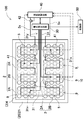
- FIG. 1 shows a schematic block diagram of a power supply device
- FIG. 2 is a schematic plan view of a seat heater laminated on a battery block of the power supply device
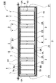
- FIG. 3 is a schematic cross-sectional view of the power supply device
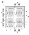
- FIG. 4 is a battery block. The plan view is shown respectively.
- the battery block 10 is housed in the battery case 20.
- a seat heater 3 for heating the battery cell 1 is arranged on the surface of the battery block 10.
- the battery block 10 is composed of a plurality of core modules 9.
- Each core module 9 includes a plurality of battery cells 1.
- a plurality of battery cells 1 are connected in parallel by a lead plate 2.
- the plurality of core modules 9 are connected in series to form the battery block 10.
- the seat heater 3 is laminated on the lead plate 2 in a heat-bonded state, and heats the battery cell 1 via the lead plate 2.
- both the heater wire 5 and the voltage detection wire 31 are insulated and wired to the base sheet 4 by a method such as sewing.
- the heater line 5 is connected to the temperature control circuit 40 to heat the battery cell 1
- the voltage detection line 31 is connected to the voltage detection circuit 30 to detect the voltage of the battery cell 1.
- the seat heater 3 is controlled by the temperature control circuit 40 to heat the battery cell 1.
- the temperature control circuit 40 includes a temperature sensor 41 that detects the temperature of the battery cell 1. When the temperature of the battery cell 1 detected by the temperature sensor 41 becomes lower than the preset minimum temperature, for example, 5 ° C., the temperature control circuit 40 energizes the battery cell 1 to heat the battery cell 1, and the battery cell 1 becomes a predetermined temperature. When the temperature rises to the set temperature, energization is stopped. Further, the temperature control circuit 40 adjusts the power supply of the seat heater 3 with the temperature of the battery cell 1 to control the heated state of the battery cell 1. The temperature control circuit 40 controls the power supply of the seat heater 3 by turning on and off the switching element 42 connected in series with the seat heater 3 at a predetermined cycle.
- the method in which the temperature control circuit 40 switches the switching element 42 on and off to control the power supply of the seat heater 3 causes transient pulse noise to be generated at the time of switching.
- a structure in which the voltage detection line 31 is wired close to the heater line 5 to the seat heater 3 causes pulse noise from the heater line 5 to be induced in the voltage detection line 31.
- This harmful effect suppresses the harmful effect of inducing pulse noise from the heater wire 5 to the voltage detection line 31 by switching the switching element 42 on and off at a low cycle of switching the switching element 42 on and off, for example, at a cycle lower than 10 Hz. it can.
- the pulse noise generated in a unit time is reduced, the pulse noise generation time is shortened with respect to the time when the pulse noise is not generated, and the pulse noise is generated in most time zones. This is because it can be prevented.
- the voltage of the battery cell 1 is input as an analog signal from the voltage detection line 31.
- the voltage detection circuit 30 is provided with an A / D converter 32 on the input side that converts the analog signal into a digital signal.
- the voltage detection circuit 30 can suppress the influence of pulse noise induced from the heater wire 5 by shifting the timing of converting the analog signal into the digital signal by the A / D converter 32 with the switching timing of the switching element 42. .. Therefore, the A / D converter 32 of the voltage detection circuit 30 sets the timing of converting the analog signal into the digital signal at a time different from the trigger signal, triggered by the timing at which the temperature control circuit 40 switches the switching element 42 on and off. Then, the input battery voltage is converted into a digital signal.
- the temperature control circuit 40 can change the power supply of the seat heater 3 by changing the duty which is a ratio to the on time and the off time of the switching element 42.
- the temperature control circuit 40 increases the on-time ratio of the switching element 42, that is, increases the duty to increase the power supply of the seat heater 3, and conversely decreases the duty to reduce the power supply of the seat heater 3. ..
- the temperature control circuit 40 increases the power supply of the seat heater 3 when the battery cell 1 is at the minimum temperature, quickly heats the battery cell 1, and supplies power as the temperature of the battery cell 1 approaches the set temperature.
- the battery cell 1 is heated without difficulty by reducing the size.
- the temperature sensor 41 is a thermistor arranged in a heat-bonded state close to the surface of the battery cell 1.
- the temperature sensor 41 detects the battery temperature by changing the electric resistance with the temperature of the battery cell 1.
- the battery temperature detected by the temperature sensor 41 is input to the temperature control circuit 40.
- the temperature control circuit 40 energizes the seat heater 3 to heat the battery cell 1, and the temperature of the heated battery cell 1 becomes the set temperature. At that time, the energization of the seat heater 3 is stopped, and when the temperature of the battery cell 1 becomes higher than the maximum temperature, the charge / discharge switch 51 is switched off to stop charging / discharging.
- the voltage detection circuit 30 is connected to the positive and negative electrodes of each battery cell 1 via the voltage detection line 31 wired to the base sheet 4 of the seat heater 3.
- the power supply device 100 of FIG. 1 connects the voltage detection line 31 to the lead plate 2 and detects the voltage of the battery cell 1.
- the voltage detection circuit 30 detects the voltage of each battery cell 1 and outputs the detected voltage of each battery cell 1 to the control unit 50.
- the control unit 50 controls the charge / discharge switch 51 to control the charge / discharge of the battery cell 1.
- the charge / discharge switch 51 is the output side of the battery cells 1 directly connected to each other, and is connected in series with the output terminal 52.
- the charge / discharge switch 51 is, for example, a semiconductor switching element such as an FET or a transistor.
- the charge / discharge switch 51 is controlled on / off by the control unit 50.
- the control unit 50 controls the charging / discharging current so as to prevent overcharging and overdischarging of each battery cell 1. For example, in the charged state, when the voltage of any battery cell 1 rises to the maximum voltage, the charging current is cut off or limited to prevent overcharging, and in the discharged state, the voltage of any battery cell 1 is the lowest. When the voltage drops, the discharge current is cut off or limited to prevent over-discharge. The control unit 50 switches the charge / discharge switch 51 from on to off to cut off the charge / discharge current.
- the voltage detection circuit 30 can also be provided with an equalization circuit to eliminate the voltage imbalance of each battery cell 1.
- the equalization circuit detects the voltage of the battery cell 1 and equalizes the detected voltage to eliminate the voltage imbalance.
- the equalization circuit detects the voltage of each battery cell 1 and discharges the battery cell 1 having a high voltage to eliminate the imbalance.
- the battery block 10 is housed in the battery case 20, and the seat heater 3 for heating the battery cells 1 constituting the battery block 10 is arranged inside the battery case 20. ..
- the battery block 10 is divided into a plurality of core modules 9, and each core module 9 includes a plurality of battery cells 1. Further, in the core module 9, the negative electrode surface 9B in which the plurality of battery cells 1 are arranged in parallel to each other and the negative electrodes 1B of the plurality of battery cells 1 are arranged in the same plane, and the positive electrodes of the plurality of battery cells 1 are arranged.
- the positive electrode surface 9A on which 1A is arranged on the same plane is arranged on the opposite surface.
- the lead plate 2 is arranged on the negative electrode surface 9B and the positive electrode surface 9A, and the negative electrode lead plate 2B of the negative electrode surface 9B is connected to the negative electrode 1B of the plurality of battery cells 1 to connect the negative electrode surface 9A.
- the positive electrode lead plate 2A of the above is connected to the positive electrode 1A of a plurality of battery cells 1 and the battery cells 1 are connected in parallel.
- the battery block 10 shown in the plan view of FIG. 4 has a plurality of core modules 9 arranged in an array in which the negative electrode surface 9B and the positive electrode surface 9A are alternately located on the same plane.
- the positive electrode surface 9A is arranged between the adjacent negative electrode surfaces 9B
- the negative electrode surface 9B is arranged between the adjacent positive electrode surfaces 9A.
- a plurality of battery cells 1 (indicated by chain lines) are arranged in multiple stages and rows, and the negative electrode surface 9B and the positive electrode surface 9A have an elongated shape.
- a plurality of core modules 9 are arranged so that the elongated negative electrode surface 9B and the positive electrode surface 9A are parallel to each other.
- a negative electrode lead plate 2B made of one metal plate is arranged on the negative electrode surface 9B, and a positive electrode lead plate 2A made of one metal plate is arranged on the positive electrode surface 9A.
- the negative electrode 1B of the battery cell 1 is welded to the negative electrode lead plate 2B and the positive electrode 1A is welded to the positive electrode lead plate 2A, and all the battery cells 1 are connected in parallel by the negative electrode lead plate 2B and the positive electrode lead plate 2A.
- the battery block 10 including a large number of core modules 9 has the core modules 9 arranged in multiple stages and rows.
- eight core modules 9 are arranged in two columns and four rows.
- the four core modules 9 arranged in each row connect the positive electrode lead plate 2A and the negative electrode lead plate 2B in series to each other in series. Since the negative electrode lead plates 2B and the positive electrode lead plates 2A are alternately arranged in the core modules 9 in each row, the adjacent lead plates 2 can be connected and the core modules 9 can be connected in series.
- the two rows of core modules 9 are connected in series or in parallel with each other.
- the core modules 9 arranged in the upper and lower rows are such that the upper row core module 9 and the lower row core module 9 are arranged in a staggered manner with the negative electrode surface 9B and the positive electrode surface 9A arranged in a staggered manner.
- the negative electrode surface 9B of the lower row core module 9 is arranged between the negative electrode surfaces 9B, and the positive electrode surface 9A of the lower row core module 9 is arranged between the positive electrode surfaces 9A of the upper row core module 9.
- both the heater wire 5 and the voltage detection wire 31 are sewn onto the non-woven fabric base sheet 4, and the insulating sheet 6 that protects the heater wire 5 is laminated on the base sheet 4.
- the base sheet 4 and the insulating sheet 6 are, for example, flexible and cushioning non-woven fabrics in which plastic fibers are three-dimensionally and non-directionally assembled.
- the heater wire 5 is a flexible resistance wire whose surface is insulated with an insulating film
- the voltage detection wire 31 is a copper wire whose surface is coated with an insulating film.
- the heater wire 5 is sewn on the surface of the base sheet 4 in a heater pattern capable of uniformly heating all the battery cells 1, and the voltage detection wire 31 can connect a specific lead plate 2 to the voltage detection circuit 30. It is sewn on the pattern.
- FIG. 5 is an enlarged cross-sectional view showing a portion where the connection portion 31x of the voltage detection line 31 drawn from the base sheet 4 is connected to the lead plate 2.
- the voltage detection line 31 draws out a portion not sewn to the base material sheet 4 from the slit 6a provided in the insulating sheet 6 to expose the connecting portion 31x from the insulating sheet 6.
- the connecting portion 31x is connected by removing the insulating film 31b and soldering or welding the conductive portion 31a to the surface of the lead plate 2.
- connection portion 31x connected to the lead plate 2 is pulled out from the base sheet 4 and the insulating sheet 6 in the vicinity of the connection portion with the lead plate 2 and is connected to the lead plate 2.
- the voltage detection line 31 having one end connected to the lead plate 2 is provided with a connection portion 31y by pulling out the other end portion from the outer peripheral edge of the base sheet 4 and the insulating sheet 6, and the connection portion 31y is connected to the voltage detection circuit 30. It is connected to the voltage detection circuit 30 by soldering to the input terminal or connecting a connector.
- Both ends of the heater wire 5 are also pulled out from the outer peripheral edges of the base sheet 4 and the insulating sheet 6 to provide a connecting portion 5x, and the connecting portion 5x is soldered or connected to a connector to be connected to the temperature control circuit 40. Ru.
- the seat heater 3 is elastically pressed against the surface of the lead plate 2 by the cushion sheet 7 to efficiently and uniformly heat the lead plate 2.
- the cushion sheet 7 an elastic sheet made of a soft plastic foam such as a soft urethane foam as an insulating material is suitable. However, a rubber-like elastic sheet that elastically deforms when pressed can also be used.
- the cushion sheet 7 is a sheet thicker than the distance between the battery case 20 and the seat heater 3 when not pressed, and the seat heater 3 is connected to the lead plate 2 in a state of being sandwiched between the battery case 20 and the seat heater 3 and crushed. Elastically presses against.
- the cushion sheet 7 has an outer shape substantially equal to the outer shape of the seat heater 3, is laminated on the surface, and elastically presses the seat heater 3 against the lead plate 2.
- the upper opening of the lower case 21 is closed by the upper case 22, and the battery block 10 is housed in the lower case 21.
- the lower case 21 and the upper case 22 are made of metal and are connected by a structure such as screwing to form a closed structure inside.
- the battery cell 1 is arranged in a holding portion provided in the plastic battery holder 8, and a plurality of battery cells 1 are arranged in a fixed position. Since the battery holder 8 is manufactured by molding plastic as an insulating material, the periphery of the core module 9 is in a state of being insulated by the battery holder 8. The periphery of the core module 9 is insulated by the battery holder 8, but the conductive portion is exposed on the surface on which the negative electrode lead plate 2B and the positive electrode lead plate 2A are arranged.
- an insulating plate 15 such as a plastic plate as an insulating material is arranged on the bottom surface 23 of the lower case 21 and the inner surface of the upper case 22.
- the bottom surface 23 of the lower case 21 and the inner surface of the upper case 22 are insulated by an insulating plate 15, and the negative electrode lead plate 2B and the positive electrode lead plate 2A come into contact with the metal battery case 20. Can be prevented.
- the insulating plate 15 that closes the upper opening of the lower case 21 is provided with an elastic bent portion 15A that is bent in a V shape on the outer peripheral edge, and the elastic bent portion 15A is combined with the battery block 10 and the lower case.
- the upper opening of the lower case 21 can be closed without a gap.
- the power supply device 100 that closes the upper opening of the lower case 21 prevents the air heated by the seat heater 3 from leaking to the outside and circulates, thereby increasing the heating efficiency of the battery cell 1 by the seat heater 3. It is possible to heat all the battery cells 1 evenly through the heated internal air.
- the above power supply device is assembled in the following steps. 1. 1. Manufacturing process of battery block 10 After setting the battery cell 1 in a fixed position of the plastic battery holder 8, the negative electrode lead plate 2B is welded to the negative electrode 1B of each battery cell 1 and the positive electrode lead plate 2A is welded to the positive electrode 1A. The battery block 10 is manufactured. Since the battery block 10 is divided into a plurality of core modules 9, each core module 9 has a negative electrode lead plate 2B welded to the negative electrode 1B side of the battery cell 1 and a positive electrode lead plate 2B to the positive electrode 1A side. 2A is welded.
- the negative electrode lead plate 2B and the positive electrode lead plate 2A are alternately arranged, but the negative electrode lead plate 2B and the positive electrode lead plate 2A are connected by the lead plate 2 and connected in series.
- the seat heater 3 is arranged on the surface of the battery block 10.
- the seat heater 3 is joined to the lead plate 2 with double-sided tape (not shown) and arranged at a fixed position.
- the connection portion 5x of the heater wire 5 drawn out from the base sheet 4 is connected to the temperature control circuit 40
- the connection portion 31x of the voltage detection line 31 is connected to the lead plate 2
- the connection portion 31y is connected to the voltage detection circuit. Connect to 30 respectively.
- the cushion sheet 7 is joined to the surface of the seat heater 3 via a double-sided adhesive tape (not shown).
- the cushion sheet 7 is also joined to the surface of the seat heater 3 so as not to be displaced.
- Step of inserting the battery block 10 into the battery case 20 With the insulating plate 15 placed on the bottom surface 23 of the lower case 21, the battery block 10 joining the seat heater 3 and the cushion sheet 7 is inserted into the lower case 21. Place in place. After that, the insulating plate 15 is arranged on the battery block 10, and the elastic bent portion 15A provided on the outer periphery of the insulating plate 15 is inserted between the peripheral wall 24 of the lower case 21 and the battery block 10. After that, the upper case 22 is fixed to the lower case 21, and the upper opening of the lower case 21 is closed by the upper case 22. The upper case 22 is fixed to the lower case 21 by screwing, for example.
- the present invention is a power supply device including a voltage detection circuit that detects the voltage of the battery cell, and is particularly provided with a seat heater that heats the battery cell in a low temperature environment, and is installed outdoors, for example, in a base station or the like. It is suitably used as a power supply device for electrical equipment used in applications where the usage environment is low, such as electrical equipment.
Landscapes
- Chemical & Material Sciences (AREA)
- Chemical Kinetics & Catalysis (AREA)
- Electrochemistry (AREA)
- General Chemical & Material Sciences (AREA)
- Engineering & Computer Science (AREA)
- Manufacturing & Machinery (AREA)
- Physics & Mathematics (AREA)
- Electromagnetism (AREA)
- Battery Mounting, Suspending (AREA)
- Secondary Cells (AREA)
Abstract
シートヒーターを利用して電圧検出線を配線することで、複数の電圧検出線を理想的な配置として、簡単かつ容易に、しかも電圧検出線を正確に定位置に配置して、高い安全性を実現する。 電源装置は、両端に正極と負極とを設けてなる複数の電池セル(1)からなる電池ブロック(10)と、電池セル(1)の電圧を検出する電圧検出回路(30)と、電圧検出回路(30)を電池セル(1)の電極に電気的に接続してなる電圧検出線(31)と、電池セル(1)を加温するシートヒーター(3)とを備え、電圧検出線(31)をシートヒーター(3)に連結している。
Description
本発明は、複数の電池セルを備える電源装置であって、電池セルの電圧を検出する電圧検出回路を備える電源装置に関する。
複数の電池セルを備える電源装置は、出力電圧を高くするために電池セルを直列に接続している。この電源装置は、直列に接続している電池セルを同じ電流で充電し、また同じ電流で放電するが、繰り返し充放電すると、各々の電池セルに電圧差が発生してアンバランスになる。電池セルのアンバランスは、特定の電池セルを過充電し、あるいは過放電して電池を劣化させる原因となる。また、特定の電池セルが異常な高電圧になると、安全性を阻害する原因にもなる。この弊害を防止するために、各々の電池セルの電圧を検出してアンバランスを解消する電源装置が開発されている。(特許文献1参照)
従来の電源装置は、電池セルに接続しているリード板に電圧検出線の一端を接続し、この電圧検出線を電圧検出回路の入力側に接続して、電圧検出回路でもって各々の電池セルの電圧を検出している。複数の電池セルを直列に接続している電源装置は、直列に接続している各々電池セルの電圧を電圧検出回路で検出するために、直列接続の各々の電池セルの電極に電圧検出線を接続している。このため、複数の電池セルを直列に接続している電源装置は、複数の電圧検出線を電池セルと電圧検出回路に接続する必要がある。電源装置は、複数の電圧検出線を配線するために、多数の部品を収納しているケース内に配線スペースを設けている。ただ、電源装置は、例外なく外形を小型化することが大切であるので、充分な配線スペースを設けることが難しく、複数の電圧検出線が狭いスペースに配置されているのが実情である。このため、電圧検出線の配線には手間がかかり、さらに狭隘なスペースに電圧検出線を配線することは、高い安全性を確保するのを阻害する原因となる。電圧検出線の絶縁皮膜の損傷が、短絡の原因となるからである。とくに、電圧検出線は電池セルの正極と負極に接続されているので、絶縁皮膜が振動や衝撃で破損して芯線が露出して、リード板や電池セルの導電部に接触すると大きなショート電流が流れて、電池セルの電気特性を低下し、さらに安全性を阻害する原因となる。
本発明は、さらに従来の電源装置が有する以上の欠点を解消することを目的に開発されたもので、本発明の目的の一は、シートヒーターを利用して電圧検出線を配線することで、複数の電圧検出線を理想的な配置として、簡単かつ容易に、しかも電圧検出線を正確に定位置に配置して、高い安全性を実現できる電源装置を提供することにある。
本発明のある態様にかかる電源装置は、両端に正極と負極とを設けてなる複数の電池セルからなる電池ブロックと、電池セルの電圧を検出する電圧検出回路と、電圧検出回路を電池セルの電極に電気的に接続してなる電圧検出線と、電池セルを加温するシートヒーターとを備える電源装置であって、電圧検出線をシートヒーターに連結している。
以上の電源装置は、電池セルを加温するために設けているシートヒーターを利用して電圧検出線を配線することで、複数の電圧検出線を理想的な配置として、簡単かつ容易に、しかも正確に定位置に配線して高い安全性を確保できる特徴がある。
以下、図面に基づいて本発明を詳細に説明する。なお、以下の説明では、必要に応じて特定の方向や位置を示す用語(例えば、「上」、「下」、及びそれらの用語を含む別の用語)を用いるが、それらの用語の使用は図面を参照した発明の理解を容易にするためであって、それらの用語の意味によって本発明の技術的範囲が制限されるものではない。また、複数の図面に表れる同一符号の部分は同一もしくは同等の部分又は部材を示す。
さらに以下に示す実施形態は、本発明の技術思想の具体例を示すものであって、本発明を以下に限定するものではない。また、以下に記載されている構成部品の寸法、材質、形状、その相対的配置等は、特定的な記載がない限り、本発明の範囲をそれのみに限定する趣旨ではなく、例示することを意図したものである。また、一の実施の形態、実施例において説明する内容は、他の実施の形態、実施例にも適用可能である。また、図面が示す部材の大きさや位置関係等は、説明を明確にするため、誇張していることがある。
さらに以下に示す実施形態は、本発明の技術思想の具体例を示すものであって、本発明を以下に限定するものではない。また、以下に記載されている構成部品の寸法、材質、形状、その相対的配置等は、特定的な記載がない限り、本発明の範囲をそれのみに限定する趣旨ではなく、例示することを意図したものである。また、一の実施の形態、実施例において説明する内容は、他の実施の形態、実施例にも適用可能である。また、図面が示す部材の大きさや位置関係等は、説明を明確にするため、誇張していることがある。
本発明の第1の態様の電源装置は、両端に正極と負極とを設けてなる複数の電池セルからなる電池ブロックと、電池セルの電圧を検出する電圧検出回路と、電圧検出回路と電池セルの電極とを電気的に接続してなる電圧検出線と、電池セルを加温するシートヒーターとを備える電源装置であって、電圧検出線をシートヒーターに連結している。
以上の電源装置は、電池セルを加温するシートヒーターに、ヒーター線と電圧検出線の両方を配線しているので、電池セルの電圧を検出するために必要な複数の電圧検出線を配線する必要がなく、シートヒーターを定位置に配置することで、電圧検出線はシートヒーターを介して正確な位置に配置できる。このため、多数の電圧検出線を配線する手間を省略しながら、電圧検出線を正確に理想的な位置に配置できる特徴がある。とくに、組み立て工程において、作業者が電圧検出線を特定の位置に配置する必要がないので、作業者の技術レベルに影響されることなく、全ての電圧検出線を、簡単で、しかも正確な位置に配置できる。さらに、電圧検出線がシートヒーターを介して定位置に配置されるので、電圧検出線が位置ずれしてショートする等の弊害を抑制して、高い安全性を実現できる特徴もある。
本発明の第2の態様の電源装置は、シートヒーターが、可撓性のある絶縁性の基材シートと、基材シートに連結してなるヒーター線と、基材シートに連結してなる電圧検出線とを備えている。
以上の電源装置は、電圧検出線を絶縁性の基材シートに連結して配線するので、電圧検出線を正確な位置に理想的な絶縁状態で配線できて、より高い安全性を確保できる。
本発明の第3の態様の電源装置は、基材シートを不織布としている。また、本発明の第4の態様の電源装置は、電圧検出線を基材シートに縫着している。この電源装置は、電圧検出線を基材シートに位置ずれしないように正確な位置に確実に配線して、より高い安全性を実現できる。
本発明の第5の態様の電源装置は、シートヒーターが、基材シートに積層してなる絶縁シートを備え、電圧検出線とヒーター線を基材シートと絶縁シートの間に配置している。
この電源装置は、電圧検出線を基材シートと絶縁シートで挟んで正確な位置に配置するので、電圧検出線をより理想的な状態で絶縁して定位置に配置して、より高い安全性を実現できる。
本発明の第6の態様の電源装置は、電圧検出線を、電池セルの電極端子に接続してなるリード板に接続して、リード板を介して電池セルの電極に電気接続している。
本発明の第7の態様の電源装置は、さらに、シートヒーターに接続されて、シートヒーターの供給電力をコントロールする温度制御回路を備え、温度制御回路が、シートヒーターの通電電流を、10Hzより低い周期でオンオフに切り換えて供給電力をコントロールしている。
以上の電源装置は、シートヒーターの供給電力を大幅に効率よくコントロールしながら、シートヒーターが発生するパルスノイズの影響を少なくて、電圧検出回路で正確に電池セルの電圧を検出できる。
本発明の第8の態様の電源装置は、電圧検出回路が、電池セルの電圧を検出してデジタル信号に変換するA/Dコンバータを備え、A/Dコンバータが、温度制御回路がシートヒーターの電流をオンオフに切り換える切換タイミングと異なるタイミングで、電池電圧をデジタル信号に変換している。
以上の電源装置は、シートヒーターの供給電力を大幅に効率よくコントロールしながら、シートヒーターが発生するパルスノイズの影響を極めて小さくして、電圧検出回路でより正確に電池セルの電圧を検出できる。
(実施の形態1)
本実施形態の電源装置は、シートヒーターで電池セルを加温するので、たとえば、基地局等のように屋外に設置される電気機器であって使用環境が低温となる用途に適している。さらに電池セルの電圧を検出しながら、電池セルの充放電をコントロールするので、各々の電池セルを理想的な状態で充放電でき、さらに、電池セルが設定電圧よりも高く、あるいは低くなることを検出して、充放電をコントロールするので、電池セルの電気特性の低下を抑制しながら、高い安全性が要求される用途に適している。
本実施形態の電源装置は、シートヒーターで電池セルを加温するので、たとえば、基地局等のように屋外に設置される電気機器であって使用環境が低温となる用途に適している。さらに電池セルの電圧を検出しながら、電池セルの充放電をコントロールするので、各々の電池セルを理想的な状態で充放電でき、さらに、電池セルが設定電圧よりも高く、あるいは低くなることを検出して、充放電をコントロールするので、電池セルの電気特性の低下を抑制しながら、高い安全性が要求される用途に適している。
図1は電源装置の概略ブロック図を示し、図2は電源装置の電池ブロックに積層しているシートヒーターの概略平面図を、図3は電源装置の概略断面図を、図4は電池ブロックの平面図をそれぞれ示している。図1~図4の電源装置100は、電池ケース20に電池ブロック10を収納している。電池ブロック10の表面には、電池セル1を加温するシートヒーター3を配置している。電池ブロック10は複数のコアモジュール9からなる。各コアモジュール9は複数の電池セル1を備える。複数の電池セル1はリード板2で並列に接続されている。複数のコアモジュール9は、直列に接続されて電池ブロック10を構成している。シートヒーター3はリード板2に熱結合状態に積層されて、リード板2を介して電池セル1を加温する。シートヒーター3は、ヒーター線5と電圧検出線31の両方を、縫着するなどの方法で基材シート4に絶縁して配線している。ヒーター線5は温度制御回路40に接続されて電池セル1を加温し、電圧検出線31は電圧検出回路30に接続されて、電池セル1の電圧を検出する。
シートヒーター3は、温度制御回路40で通電状態がコントロールされて、電池セル1を加温する。温度制御回路40は、電池セル1の温度を検出する温度センサ41を備えている。温度制御回路40は、温度センサ41で検出する電池セル1の温度が予め設定している最低温度、たとえば5℃よりも低くなると通電して電池セル1を加温し、電池セル1が所定の設定温度まで上昇すると通電を停止する。さらに、温度制御回路40は、シートヒーター3の供給電力を電池セル1の温度で調整して、電池セル1の加温状態をコントロールする。温度制御回路40は、シートヒーター3に直列に接続しているスイッチング素子42を、所定の周期でオンオフしてシートヒーター3の供給電力をコントロールする。
温度制御回路40がスイッチング素子42をオンオフに切り換えて、シートヒーター3の供給電力をコントロールする方式は、切り換え時に過渡的にパルスノイズが発生する原因となる。とくに、電圧検出線31をヒーター線5に接近してシートヒーター3に配線する構造は、ヒーター線5からのパルスノイズが電圧検出線31に誘導される原因となる。この弊害は、スイッチング素子42をオンオフに切り換える周期を低く、たとえば10Hzより低い周期でスイッチング素子42をオンオフに切り換えることで、ヒーター線5からのパルスノイズの電圧検出線31への誘導による弊害を抑制できる。オンオフの周期を低くすることで、単位時間に発生するパルスノイズを少なくして、パルスノイズの発生時間を、パルスノイズが発生しない時間に対して短くして、ほとんどの時間帯においてパルスノイズが発生しないようにできるからである。
電圧検出回路30は、電圧検出線31から電池セル1の電圧がアナログ信号として入力される。入力されるアナログ信号をデジタル信号に変換するために、電圧検出回路30は、入力側にアナログ信号をデジタル信号に変換するA/Dコンバータ32を設けている。この電圧検出回路30は、A/Dコンバータ32でアナログ信号をデジタル信号に変換するタイミングを、スイッチング素子42の切り換えタイミングとずらせることで、ヒーター線5から誘導されるパルスノイズの影響を抑制できる。したがって、電圧検出回路30のA/Dコンバータ32は、温度制御回路40がスイッチング素子42をオンオフに切り換えるタイミングをトリガーとして、アナログ信号をデジタル信号に変換するタイミングを、トリガー信号と異なる時間に設定して、入力される電池電圧をデジタル信号に変換する。
温度制御回路40は、スイッチング素子42のオン時間とオフ時間に比率であるデューティーを変更して、シートヒーター3の供給電力を変更できる。温度制御回路40は、スイッチング素子42のオン時間の比率を大きく、すなわちデューティーを大きくしてシートヒーター3の供給電力を大きくし、反対にデューティーを小さくして、シートヒーター3の供給電力を小さくする。温度制御回路40は、電池セル1が最低温度のときはシートヒーター3の供給電力を大きくして、速やかに電池セル1を加温し、電池セル1の温度が設定温度に近づくにしたがって供給電力を小さくして無理なく電池セル1を加温する。温度センサ41は、電池セル1の表面に接近して熱結合状態で配設されるサーミスタである。温度センサ41は、電池セル1の温度で電気抵抗が変化して電池温度を検出する。温度センサ41で検出された電池温度は、温度制御回路40に入力される。温度制御回路40は、温度センサ41で検出される電池温度が最低温度よりも低下すると、シートヒーター3に通電して電池セル1を加温し、加温された電池セル1の温度が設定温度になるとシートヒーター3の通電を停止し、さらに、電池セル1の温度が最高温度よりも高くなると、充放電スイッチ51をオフに切り換えて充電や放電を停止する。
電圧検出回路30は、シートヒーター3の基材シート4に配線している電圧検出線31を介して各電池セル1の正負の電極に接続される。図1の電源装置100は、電圧検出線31をリード板2に接続して、電池セル1の電圧を検出する。電圧検出回路30は、各電池セル1の電圧を検出すると共に、検出された各電池セル1の電圧を制御部50に出力している。制御部50は、充放電スイッチ51を制御して、電池セル1の充放電をコントロールする。充放電スイッチ51は、互いに直接に接続された電池セル1の出力側であって、出力端子52との間に直列に接続されている。充放電スイッチ51は、例えば、FETやトランジスタ等の半導体スイッチング素子である。充放電スイッチ51は、制御部50によってオンオフが制御される。
制御部50は、各電池セル1の過充電と過放電を防止するように、充放電の電流をコントロールする。たとえば、充電状態において、何れかの電池セル1の電圧が最大電圧まで上昇すると充電電流を遮断し、あるいは制限して過充電を防止し、放電状態において、何れかの電池セル1の電圧が最低電圧まで低下すると、放電電流を遮断し、あるいは制限して過放電を防止する。制御部50は、充放電スイッチ51をオンからオフに切り換えて充放電電流を遮断する。
電圧検出回路30は、均等化回路を設けて、各電池セル1の電圧のアンバランスを解消することもできる。均等化回路は、電池セル1の電圧を検出し、検出する電圧を均等化して電圧のアンバランスを解消する。均等化回路は、各々の電池セル1の電圧を検出して、電圧の高い電池セル1を放電してアンバランスを解消する。
図1ないし図4に示す電源装置は、電池ブロック10を電池ケース20に収納して、電池ブロック10を構成する電池セル1を加温するシートヒーター3を電池ケース20の内側に配置している。電池ブロック10は、複数のコアモジュール9に分割されて、各々のコアモジュール9は、複数の電池セル1を備える。さらに、このコアモジュール9は、複数の電池セル1を互いに平行姿勢に配置して、複数の電池セル1の負極1Bを同一平面に配置している負極表面9Bと、複数の電池セル1の正極1Aを同一平面に配置している正極表面9Aとを対向面に配置している。さらにまた、コアモジュール9は、負極表面9Bと正極表面9Aにリード板2を配置して、負極表面9Bの負極リード板2Bは、複数の電池セル1の負極1Bに接続して、正極表面9Aの正極リード板2Aは、複数の電池セル1の正極1Aに接続されて、電池セル1を並列に接続している。
図4の平面図に示す電池ブロック10は、負極表面9Bと正極表面9Aとを交互に同一平面に位置する配列で、複数のコアモジュール9を配置している。この電池ブロック10は、隣接する負極表面9Bの間に正極表面9Aを配置して、隣接する正極表面9Aの間に負極表面9Bを配置している。図4のコアモジュール9は、複数の電池セル1(鎖線で示している)を多段多列に配置して、負極表面9Bと正極表面9Aを細長い形状としている。電池ブロック10は、複数のコアモジュール9を、細長い負極表面9Bと正極表面9Aとが互いに平行となるように並べている。コアモジュール9は、図3に示すように、負極表面9Bに1枚の金属板からなる負極リード板2Bを配置し、正極表面9Aには1枚の金属板からなる正極リード板2Aを配置して、電池セル1の負極1Bを負極リード板2Bに、正極1Aを正極リード板2Aに溶着して、全ての電池セル1を負極リード板2Bと正極リード板2Aで並列に接続している。
多数のコアモジュール9を備える電池ブロック10は、コアモジュール9を多段多列に配置している。図4の平面図に示す電池ブロック10は、8個のコアモジュール9を2つの列と、4つの行に配置している。各列に配置された4つのコアモジュール9は、正極リード板2Aと負極リード板2Bを直列に接続して、互いに直列に接続している。各列のコアモジュール9は、負極リード板2Bと正極リード板2Aを交互に配置しているので、隣のリード板2を接続してコアモジュール9を直列に接続できる。2列のコアモジュール9は、互いに直列又は並列に接続される。
図において上下2列に配置しているコアモジュール9は、上列のコアモジュール9と下列のコアモジュール9を、負極表面9Bと正極表面9Aとを千鳥に配置して、上列コアモジュール9の負極表面9Bの間には下列コアモジュール9の負極表面9Bを配置して、上列コアモジュール9の正極表面9Aの間には下列コアモジュール9の正極表面9Aを配置している。
シートヒーター3は、不織布製の基材シート4にヒーター線5と電圧検出線31の両方を縫着して、基材シート4に、ヒーター線5を保護する絶縁シート6を積層している。基材シート4と絶縁シート6は、たとえば、プラスチック繊維を立体的に方向性なく集合している可撓性とクッション性のある不織布である。ヒーター線5は、表面を絶縁皮膜で絶縁している可撓性のある抵抗線で、電圧検出線31は表面を絶縁皮膜で被覆している銅線である。ヒーター線5は、基材シート4の表面に、全ての電池セル1を均一に加温できるヒーターパターンに縫着され、電圧検出線31は、特定のリード板2を電圧検出回路30に接続できるパターンに縫着されている。
ヒーター線5と電圧検出線31は、両端部に基材シート4に縫着されない引き出し部を設けて接続部5x、31x、31yとしている。図5は、基材シート4から引き出された電圧検出線31の接続部31xをリード板2に接続する部分を示す拡大断面図である。電圧検出線31は、基材シート4に縫着されない部分を絶縁シート6に設けたスリット6aから引き出して、接続部31xを絶縁シート6から表出させている。接続部31xは、絶縁皮膜31bを除去して導電部31aをリード板2の表面にハンダ付けし、あるいは溶着して接続している。リード板2に接続される接続部31xは、リード板2との接続部分の近傍で基材シート4と絶縁シート6から引き出されて、リード板2に接続される。一端をリード板2に接続している電圧検出線31は、他の端部を基材シート4と絶縁シート6の外周縁から引き出して接続部31yを設け、接続部31yを電圧検出回路30の入力端子にハンダ付けし、あるいはコネクタを接続して電圧検出回路30に接続される。ヒーター線5も、両端部を基材シート4と絶縁シート6の外周縁から引き出して接続部5xを設け、この接続部5xをハンダ付けし、あるいはコネクタに接続して温度制御回路40に接続される。
シートヒーター3は、クッションシート7でリード板2の表面に弾性的に押圧されて、リード板2を効率よく均一に加温する。クッションシート7は、絶縁材である軟質ウレタンフォーム等の軟質プラスチック発泡体の弾性シートが適している。ただ、押圧して弾性変形するゴム状弾性のシートも使用できる。クッションシート7は、押圧しない状態では、電池ケース20とシートヒーター3の間隔よりも厚いシートで、電池ケース20とシートヒーター3に挟まれて押し潰された状態で、シートヒーター3をリード板2に弾性的に押圧する。クッションシート7は、シートヒーター3の外形にほぼ等しい外形で、表面に積層されてシートヒーター3をリード板2に弾性的に押圧する。
図3の概略断面図に示す電池ケース20は、下ケース21の上方開口部を上ケース22で閉塞して、下ケース21に電池ブロック10を収納している。下ケース21と上ケース22は金属製で、ネジ止め等の構造で連結されて、内部を閉鎖構造としている。電池ブロック10のコアモジュール9は、プラスチック製の電池ホルダー8に設けた保持部に電池セル1を配置して、複数の電池セル1を定位置に配置している。電池ホルダー8は絶縁材のプラスチックを成形して製作されるので、コアモジュール9の周囲は電池ホルダー8で絶縁された状態となる。コアモジュール9は、周囲を電池ホルダー8で絶縁しているが、負極リード板2Bと正極リード板2Aを配置している面は、導電部が露出している。
図3の概略断面図に示す電池ケース20は、下ケース21の底面23と、上ケース22の内面に、絶縁材のプラスチック板などの絶縁プレート15を配置している。この構造の電源装置100は、絶縁プレート15で下ケース21の底面23と、上ケース22の内面を絶縁して、負極リード板2Bと正極リード板2Aが金属製の電池ケース20に接触するのを防止できる。下ケース21の上方開口部を閉塞する絶縁プレート15は、図に示すように、外周縁にV字状に折り曲げした弾性折り曲げ部15Aを設け、この弾性折り曲げ部15Aを、電池ブロック10と下ケース21の周壁24との隙間に挿入して、下ケース21の上方開口部を隙間なく閉塞できる。下ケース21の上方開口部を閉塞する電源装置100は、シートヒーター3で加温された空気が外部に漏れて循環するのを防止して、シートヒーター3による電池セル1の加温効率を高くでき、さらに加温された内部空気を介して全ての電池セル1を均等に加温できる特徴がある。
以上の電源装置は、以下の工程で組み立てられる。
1.電池ブロック10の製造工程
プラスチック製の電池ホルダー8の定位置に電池セル1をセットした後、各々の電池セル1の負極1Bに負極リード板2Bを、正極1Aには正極リード板2Aを溶着して電池ブロック10を製造する。
電池ブロック10は、複数のコアモジュール9に分割しているので、各々のコアモジュール9は、電池セル1の負極1B側には負極リード板2Bを溶着して、正極1A側には正極リード板2Aが溶着される。隣接するコアモジュール9は、負極リード板2Bと正極リード板2Aとが交互に配置しているが、負極リード板2Bと正極リード板2Aとをリード板2で接続して直列に接続される。ただ、隣接するコアモジュール9の反対側のリード板2を接続して、隣接するコアモジュール9を並列に接続することもできる。
1.電池ブロック10の製造工程
プラスチック製の電池ホルダー8の定位置に電池セル1をセットした後、各々の電池セル1の負極1Bに負極リード板2Bを、正極1Aには正極リード板2Aを溶着して電池ブロック10を製造する。
電池ブロック10は、複数のコアモジュール9に分割しているので、各々のコアモジュール9は、電池セル1の負極1B側には負極リード板2Bを溶着して、正極1A側には正極リード板2Aが溶着される。隣接するコアモジュール9は、負極リード板2Bと正極リード板2Aとが交互に配置しているが、負極リード板2Bと正極リード板2Aとをリード板2で接続して直列に接続される。ただ、隣接するコアモジュール9の反対側のリード板2を接続して、隣接するコアモジュール9を並列に接続することもできる。
2.電池ブロック10に、シートヒーター3を積層する工程
電池ブロック10の表面にシートヒーター3を配置する。シートヒーター3は、両面テープ(図示せず)でリード板2に接合して定位置に配置する。シートヒーター3は、基材シート4から引き出しているヒーター線5の接続部5xを温度制御回路40に接続し、電圧検出線31の接続部31xをリード板2に、接続部31yを電圧検出回路30にそれぞれ接続する。
電池ブロック10の表面にシートヒーター3を配置する。シートヒーター3は、両面テープ(図示せず)でリード板2に接合して定位置に配置する。シートヒーター3は、基材シート4から引き出しているヒーター線5の接続部5xを温度制御回路40に接続し、電圧検出線31の接続部31xをリード板2に、接続部31yを電圧検出回路30にそれぞれ接続する。
3.シートヒーター3にクッションシート7を接合する工程
シートヒーター3の表面に、両面接着テープ(図示せず)を介してクッションシート7を接合する。クッションシート7も位置ずれしないように、シートヒーター3の表面に接合する。
シートヒーター3の表面に、両面接着テープ(図示せず)を介してクッションシート7を接合する。クッションシート7も位置ずれしないように、シートヒーター3の表面に接合する。
4.電池ブロック10を電池ケース20に挿入する工程
下ケース21の底面23に絶縁プレート15を配置する状態で、シートヒーター3とクッションシート7を接合している電池ブロック10を下ケース21に挿入して定位置に配置する。その後、電池ブロック10の上に絶縁プレート15を配置して、絶縁プレート15の外周に設けた弾性折り曲げ部15Aを下ケース21の周壁24と電池ブロック10の間に挿入する。
その後、下ケース21に上ケース22を固定して、下ケース21の上方開口部を上ケース22で閉塞する。上ケース22は、たとえば、ネジ止めして下ケース21に固定される。
下ケース21の底面23に絶縁プレート15を配置する状態で、シートヒーター3とクッションシート7を接合している電池ブロック10を下ケース21に挿入して定位置に配置する。その後、電池ブロック10の上に絶縁プレート15を配置して、絶縁プレート15の外周に設けた弾性折り曲げ部15Aを下ケース21の周壁24と電池ブロック10の間に挿入する。
その後、下ケース21に上ケース22を固定して、下ケース21の上方開口部を上ケース22で閉塞する。上ケース22は、たとえば、ネジ止めして下ケース21に固定される。
本発明は、電池セルの電圧を検出する電圧検出回路を備える電源装置であって、とくに、低温環境で電池セルを加温するシートヒーターを備えて、たとえば、基地局等の屋外に設置される電気機器のように、使用環境が低温となる用途で使用される電気機器用の電源装置として好適に使用される。
100…電源装置
1…電池セル
1A…正極
1B…負極
2…リード板
2A…正極リード板
2B…負極リード板
3…シートヒーター
4…基材シート
5…ヒーター線
5x…接続部
6…絶縁シート
6a…スリット
7…クッションシート
8…電池ホルダー
9…コアモジュール
9A…正極表面
9B…負極表面
10…電池ブロック
15…絶縁プレート
15A…弾性折り曲げ部
20…電池ケース
21…下ケース
22…上ケース
23…底面
24…周壁
30…電圧検出回路
31…電圧検出線
31a…導電部
31b…絶縁皮膜
31x、31y…接続部
32…A/Dコンバータ
40…温度制御回路
41…温度センサ
42…スイッチング素子
50…制御部
51…充放電スイッチ
52…出力端子
1…電池セル
1A…正極
1B…負極
2…リード板
2A…正極リード板
2B…負極リード板
3…シートヒーター
4…基材シート
5…ヒーター線
5x…接続部
6…絶縁シート
6a…スリット
7…クッションシート
8…電池ホルダー
9…コアモジュール
9A…正極表面
9B…負極表面
10…電池ブロック
15…絶縁プレート
15A…弾性折り曲げ部
20…電池ケース
21…下ケース
22…上ケース
23…底面
24…周壁
30…電圧検出回路
31…電圧検出線
31a…導電部
31b…絶縁皮膜
31x、31y…接続部
32…A/Dコンバータ
40…温度制御回路
41…温度センサ
42…スイッチング素子
50…制御部
51…充放電スイッチ
52…出力端子
Claims (8)
- 両端に正極と負極とを設けてなる複数の電池セルからなる電池ブロックと、
前記電池セルの電圧を検出する電圧検出回路と、
前記電圧検出回路と前記電池セルの電極とを電気的に接続してなる電圧検出線と、
前記電池セルを加温するシートヒーターと、
を備える電源装置であって、
前記電圧検出線が前記シートヒーターに連結されてなることを特徴とする電源装置。 - 請求項1に記載する電源装置であって、
前記シートヒーターが、
可撓性のある絶縁性の基材シートと、
前記基材シートに連結してなるヒーター線と、
前記基材シートに連結してなる前記電圧検出線とを備えることを特徴とする電源装置。 - 請求項2に記載する電源装置であって、
前記基材シートが不織布であることを特徴とする電源装置。 - 請求項2または3に記載する電源装置であって、
前記電圧検出線が前記基材シートに縫着されてなることを特徴とする電源装置。 - 請求項2ないし4のいずれかに記載する電源装置であって、
前記シートヒーターが、
前記基材シートに積層してなる絶縁シートを備え、
前記電圧検出線と前記ヒーター線が前記基材シートと前記絶縁シートの間に配置されてなることを特徴とする電源装置。 - 請求項1ないし5のいずれかに記載する電源装置であって、
前記電圧検出線が、
前記電池セルの電極端子に接続してなるリード板に接続され、
前記リード板を介して前記電池セルの電極に電気接続されてなることを特徴とする電源装置。 - 請求項1ないし6のいずれかに記載する電源装置であって、さらに、
前記シートヒーターに接続されて、前記シートヒーターの供給電力をコントロールする温度制御回路を備え、
前記温度制御回路が、
前記シートヒーターの通電電流を、10Hzより低い周期でオンオフに切り換えて供給電力をコントロールすることを特徴とする電源装置。 - 請求項7に記載する電源装置であって。
前記電圧検出回路が、
前記電池セルの電圧を検出してデジタル信号に変換するA/Dコンバータを備え、
前記A/Dコンバータが、
前記温度制御回路が前記シートヒーターの電流をオンオフに切り換える切換タイミングと異なるタイミングで、電池電圧をデジタル信号に変換することを特徴とする電源装置。
Applications Claiming Priority (2)
| Application Number | Priority Date | Filing Date | Title |
|---|---|---|---|
| JP2019-064715 | 2019-03-28 | ||
| JP2019064715A JP2022078382A (ja) | 2019-03-28 | 2019-03-28 | 電源装置 |
Publications (1)
| Publication Number | Publication Date |
|---|---|
| WO2020195422A1 true WO2020195422A1 (ja) | 2020-10-01 |
Family
ID=72611809
Family Applications (1)
| Application Number | Title | Priority Date | Filing Date |
|---|---|---|---|
| PCT/JP2020/007026 Ceased WO2020195422A1 (ja) | 2019-03-28 | 2020-02-21 | 電源装置 |
Country Status (2)
| Country | Link |
|---|---|
| JP (1) | JP2022078382A (ja) |
| WO (1) | WO2020195422A1 (ja) |
Citations (4)
| Publication number | Priority date | Publication date | Assignee | Title |
|---|---|---|---|---|
| JP2013211436A (ja) * | 2012-03-30 | 2013-10-10 | Mitsubishi Materials Corp | 温度調節機能付き電池 |
| JP2017134973A (ja) * | 2016-01-27 | 2017-08-03 | トヨタ自動車株式会社 | 電池モジュール |
| WO2018101005A1 (ja) * | 2016-11-30 | 2018-06-07 | 日立オートモティブシステムズ株式会社 | 電池制御装置 |
| JP2018096803A (ja) * | 2016-12-13 | 2018-06-21 | 住友電気工業株式会社 | 内部抵抗算出装置、内部抵抗算出方法および内部抵抗算出プログラム |
-
2019
- 2019-03-28 JP JP2019064715A patent/JP2022078382A/ja active Pending
-
2020
- 2020-02-21 WO PCT/JP2020/007026 patent/WO2020195422A1/ja not_active Ceased
Patent Citations (4)
| Publication number | Priority date | Publication date | Assignee | Title |
|---|---|---|---|---|
| JP2013211436A (ja) * | 2012-03-30 | 2013-10-10 | Mitsubishi Materials Corp | 温度調節機能付き電池 |
| JP2017134973A (ja) * | 2016-01-27 | 2017-08-03 | トヨタ自動車株式会社 | 電池モジュール |
| WO2018101005A1 (ja) * | 2016-11-30 | 2018-06-07 | 日立オートモティブシステムズ株式会社 | 電池制御装置 |
| JP2018096803A (ja) * | 2016-12-13 | 2018-06-21 | 住友電気工業株式会社 | 内部抵抗算出装置、内部抵抗算出方法および内部抵抗算出プログラム |
Also Published As
| Publication number | Publication date |
|---|---|
| JP2022078382A (ja) | 2022-05-25 |
Similar Documents
| Publication | Publication Date | Title |
|---|---|---|
| EP3249716B1 (en) | In-vehicle battery module | |
| CN100409484C (zh) | 多电池充电装置 | |
| JP3003243B2 (ja) | バッテリー | |
| EP1839349B1 (en) | Sensing board assembly for secondary battery module | |
| KR101913786B1 (ko) | 단자 플레이트 및 bms가 직접 연결된 구조의 전지모듈 | |
| EP3128574A1 (en) | Circuit board for secondary battery and battery pack comprising same | |
| US20110135992A1 (en) | Battery module and battery pack including the same | |
| US20170331097A1 (en) | Method for welding electrode leads of secondary battery module and compact secondary battery module using the same | |
| CN100426584C (zh) | 充电器 | |
| US10367180B2 (en) | Battery pack | |
| US11799143B2 (en) | Battery pack | |
| KR102666368B1 (ko) | 배터리 팩 | |
| US8518576B2 (en) | Secondary battery including a sensor to determine if battery is heated above a predetermined temperature | |
| EP2905824A1 (en) | Battery pack | |
| US20130108894A1 (en) | Secondary battery | |
| JP4712929B2 (ja) | 組電池の異常温度検出装置 | |
| KR20190094025A (ko) | 배터리 보호회로 및 이를 갖는 배터리 팩 | |
| KR102459621B1 (ko) | 배터리 팩 | |
| US20200365865A1 (en) | Bus Bar Module | |
| WO2020195422A1 (ja) | 電源装置 | |
| KR20200102187A (ko) | 배터리 팩 | |
| KR101985836B1 (ko) | 배터리팩 | |
| KR101678529B1 (ko) | 접속 부재를 지지하기 위한 돌출부를 포함하는 이차전지 | |
| EP3952008B1 (en) | Power supply device | |
| KR101074992B1 (ko) | 이차전지용 배터리 셀 단자 |
Legal Events
| Date | Code | Title | Description |
|---|---|---|---|
| 121 | Ep: the epo has been informed by wipo that ep was designated in this application |
Ref document number: 20779000 Country of ref document: EP Kind code of ref document: A1 |
|
| NENP | Non-entry into the national phase |
Ref country code: DE |
|
| 122 | Ep: pct application non-entry in european phase |
Ref document number: 20779000 Country of ref document: EP Kind code of ref document: A1 |
|
| NENP | Non-entry into the national phase |
Ref country code: JP |