WO2020195247A1 - 赤外線センサ用カバー - Google Patents
赤外線センサ用カバー Download PDFInfo
- Publication number
- WO2020195247A1 WO2020195247A1 PCT/JP2020/005096 JP2020005096W WO2020195247A1 WO 2020195247 A1 WO2020195247 A1 WO 2020195247A1 JP 2020005096 W JP2020005096 W JP 2020005096W WO 2020195247 A1 WO2020195247 A1 WO 2020195247A1
- Authority
- WO
- WIPO (PCT)
- Prior art keywords
- infrared sensor
- heater wire
- infrared
- cover
- vehicle
- Prior art date
- Legal status (The legal status is an assumption and is not a legal conclusion. Google has not performed a legal analysis and makes no representation as to the accuracy of the status listed.)
- Ceased
Links
Images



Classifications
-
- B—PERFORMING OPERATIONS; TRANSPORTING
- B60—VEHICLES IN GENERAL
- B60R—VEHICLES, VEHICLE FITTINGS, OR VEHICLE PARTS, NOT OTHERWISE PROVIDED FOR
- B60R21/00—Arrangements or fittings on vehicles for protecting or preventing injuries to occupants or pedestrians in case of accidents or other traffic risks
-
- G—PHYSICS
- G01—MEASURING; TESTING
- G01J—MEASUREMENT OF INTENSITY, VELOCITY, SPECTRAL CONTENT, POLARISATION, PHASE OR PULSE CHARACTERISTICS OF INFRARED, VISIBLE OR ULTRAVIOLET LIGHT; COLORIMETRY; RADIATION PYROMETRY
- G01J1/00—Photometry, e.g. photographic exposure meter
- G01J1/02—Details
-
- G—PHYSICS
- G01—MEASURING; TESTING
- G01J—MEASUREMENT OF INTENSITY, VELOCITY, SPECTRAL CONTENT, POLARISATION, PHASE OR PULSE CHARACTERISTICS OF INFRARED, VISIBLE OR ULTRAVIOLET LIGHT; COLORIMETRY; RADIATION PYROMETRY
- G01J1/00—Photometry, e.g. photographic exposure meter
- G01J1/02—Details
- G01J1/04—Optical or mechanical part supplementary adjustable parts
-
- G—PHYSICS
- G01—MEASURING; TESTING
- G01S—RADIO DIRECTION-FINDING; RADIO NAVIGATION; DETERMINING DISTANCE OR VELOCITY BY USE OF RADIO WAVES; LOCATING OR PRESENCE-DETECTING BY USE OF THE REFLECTION OR RERADIATION OF RADIO WAVES; ANALOGOUS ARRANGEMENTS USING OTHER WAVES
- G01S7/00—Details of systems according to groups G01S13/00, G01S15/00, G01S17/00
- G01S7/48—Details of systems according to groups G01S13/00, G01S15/00, G01S17/00 of systems according to group G01S17/00
- G01S7/481—Constructional features, e.g. arrangements of optical elements
-
- G—PHYSICS
- G01—MEASURING; TESTING
- G01V—GEOPHYSICS; GRAVITATIONAL MEASUREMENTS; DETECTING MASSES OR OBJECTS; TAGS
- G01V8/00—Prospecting or detecting by optical means
- G01V8/10—Detecting, e.g. by using light barriers
- G01V8/12—Detecting, e.g. by using light barriers using one transmitter and one receiver
-
- G—PHYSICS
- G02—OPTICS
- G02B—OPTICAL ELEMENTS, SYSTEMS OR APPARATUS
- G02B5/00—Optical elements other than lenses
- G02B5/02—Diffusing elements; Afocal elements
-
- H—ELECTRICITY
- H05—ELECTRIC TECHNIQUES NOT OTHERWISE PROVIDED FOR
- H05B—ELECTRIC HEATING; ELECTRIC LIGHT SOURCES NOT OTHERWISE PROVIDED FOR; CIRCUIT ARRANGEMENTS FOR ELECTRIC LIGHT SOURCES, IN GENERAL
- H05B3/00—Ohmic-resistance heating
- H05B3/10—Heating elements characterised by the composition or nature of the materials or by the arrangement of the conductor
Definitions
- This disclosure relates to a cover for an infrared sensor.
- Vehicles such as automobiles are equipped with infrared sensors that transmit and receive infrared rays.
- This infrared sensor is for transmitting infrared rays to the outside of the vehicle, receiving the infrared rays reflected by hitting an object outside the vehicle, and detecting the object outside the vehicle through transmission / reception of such infrared rays.
- a cover for the infrared sensor is provided so that the infrared sensor cannot be seen directly from the outside of the vehicle.
- Patent Document 1 As the cover for the infrared sensor, as shown in Patent Document 1, a cover base material located on the path of infrared rays transmitted and received by the infrared sensor, and a heater provided on the surface of the cover base material and generating heat by energization. Those with lines are known. In such an infrared sensor cover, ice and snow adhering to the infrared sensor cover (cover base material) are melted through the heat generated by the heater wire. As a result, the transmission of infrared rays is hindered due to the adhesion of ice and snow to the cover for the infrared sensor, and the deterioration of the detection performance of the infrared sensor is suppressed.
- the infrared rays transmitted from the infrared sensor are reflected by the heater wire, and the reflected infrared rays are received by the infrared sensor. It may adversely affect the detection function.
- An object of the present disclosure is to provide a cover for an infrared sensor that can suppress an adverse effect on the detection function of the infrared sensor due to reflection of infrared rays transmitted from the infrared sensor by a heater wire.
- the infrared sensor cover that solves the above problems includes a cover base material provided on the path of infrared rays transmitted and received by the infrared sensor, and a heater wire provided on the surface of the cover base material and generating heat by energization. Then, a large number of irregularities are formed on the surface of the heater wire.
- the infrared rays transmitted from the infrared sensor hit the heater wire, the infrared rays are scattered by a large number of irregularities formed on the surface of the heater wire. Therefore, it is possible to prevent the infrared rays from being reflected by the surface of the heater wire and being received by the infrared sensor. Therefore, when the infrared rays reflected by the heater wire are received by the infrared sensor, it is suppressed that the detection function of the infrared sensor is adversely affected.
- the heater wire is formed in a thin and flat plate shape, and the maximum depth of the unevenness is preferably 30 to 80% of the thickness of the heater wire.
- the infrared sensor is mounted on the vehicle and transmits infrared rays to the outside of the vehicle, while receiving the infrared rays reflected by an object outside the vehicle, and the cover base material is obtained from the infrared sensor.
- the heater wire is formed in a thin, elongated flat plate shape having a thickness in the direction of approaching and separating from the infrared sensor, and the unevenness is at least on the infrared sensor side on the surface of the heater wire. It is preferable that it is formed on the surface of.
- the infrared rays transmitted from the infrared sensor easily hit the surface of the heater wire on the infrared sensor side. Since a large number of irregularities are formed on at least the surface of the heater wire on the infrared sensor side, the infrared rays transmitted from the infrared sensor are likely to be scattered when they hit the heater wire.
- (A) is a schematic view showing an infrared sensor and an infrared sensor cover mounted on a vehicle
- (b) is an enlarged cross-sectional view showing a portion of the infrared sensor cover of (a) surrounded by a two-point chain line.
- the front view which shows the state which the heater wire was seen from the left side of FIG. 1 (b).
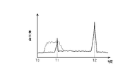
- a time chart showing the time transition of the detected value of the infrared sensor after transmitting infrared rays from the infrared sensor.
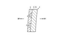
- An enlarged sectional view showing another example of a cover for an infrared sensor.
- the schematic diagram which shows another example of the cover for an infrared sensor.
- Enlarged sectional view showing another example of the heater wire.
- the infrared radar device 1 includes an infrared sensor 3 housed in a case 2.
- the infrared sensor 3 transmits infrared rays toward the outside of the vehicle (left side in FIG. 1), receives the infrared rays reflected by the objects outside the vehicle, and detects the objects outside the vehicle through the transmission and reception of such infrared rays.
- the case 2 is open toward the front (left side in FIG. 1) in the infrared transmission direction of the infrared sensor 3.
- An infrared sensor cover 4 is attached to the opening of the case 2 so that the infrared sensor 3 cannot be seen directly from the outside of the vehicle.
- the infrared sensor cover 4 includes the cover base material 5.
- the cover base material 5 includes a base layer 6 and a transparent film 7.
- the base layer 6 is formed of a transparent resin such as PET (polyethylene terephthalate).
- the transparent film 7 covers the surface of the base layer 6 opposite to the infrared sensor 3 (the surface on the left side of FIG. 1B).
- the cover base material 5 is on the path of infrared rays transmitted and received by the infrared sensor 3 (FIG. 1 (a)), and is located outside the vehicle from the infrared sensor 3.
- a copper heater wire 8 that generates heat when energized and a protective layer 9 that covers the heater wire 8 and the transparent film 7 are provided on the surface of the cover base material 5 (transparent film 7) opposite to the infrared sensor 3, a copper heater wire 8 that generates heat when energized and a protective layer 9 that covers the heater wire 8 and the transparent film 7 are provided. ..
- the protective layer 9 is formed of a transparent resin such as PET.
- An AR coat layer 10 is formed on the surface of the protective layer 9 opposite to the infrared sensor 3 by an antireflection coating.
- the cover base material 5, the protective layer 9, and the AR coat layer 10 in the infrared sensor cover 4 can transmit infrared rays transmitted and received by the infrared sensor 3.
- the infrared sensor cover 4 When ice and snow adhere to the infrared sensor cover 4, the ice and snow are melted through the heat generated by the heater wire 8 due to energization. By melting the ice and snow adhering to the infrared sensor cover 4 in this way, it is possible to prevent the infrared sensor 3 from deteriorating the detection performance due to the hindrance of infrared transmission due to the adhesion of the ice and snow.
- the heater wire 8 is formed in a flat plate shape having a thickness in the direction of approaching and separating from the infrared sensor 3 (FIG. 1 (a)), that is, in the left-right direction of FIG. 1 (b). ing.
- FIG. 1B the thickness in the left-right direction in the drawing is drawn larger than the actual thickness in order to make the heater wire 8 easier to see.
- FIG. 2 shows a state in which the heater wire 8 is viewed from the left side of FIG. 1 (b).
- the heater wire 8 is provided so as to extend in the left-right direction of FIG. 2 and reciprocate in the left-right direction thereof. A predetermined interval is provided between the portions extending in parallel in the heater wire 8.
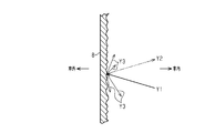
- FIG. 3 shows an enlarged cross section of the heater wire 8.
- a large number of irregularities are formed on the surface of the heater wire 8.
- a large number of irregularities are formed on at least the surface of the heater wire 8 on the infrared sensor 3 side, that is, the right surface of FIG.
- a large number of the above-mentioned irregularities are formed on the surface of the heater wire 8 on the infrared sensor 3 side and on both side surfaces of the heater wire 8 in the width direction (vertical direction in FIG. 3).
- the unevenness is not formed on the surface of the heater wire 8 opposite to the infrared sensor 3, that is, the left surface of FIG.
- the large number of irregularities on the heater wire 8 are formed by etching.
- the maximum depth of a large number of irregularities can be 30-80% of the thickness of the heater wire 8, preferably 50-75%, more preferably 40-70%. preferable.
- the maximum depth of the large number of irregularities is set to be 60% of the thickness of the heater wire 8.
- a part of the infrared rays transmitted from the infrared sensor 3 toward the outside of the vehicle does not pass through the infrared sensor cover 4, but hits the heater wire 8 as shown by an arrow Y1 in FIG. 3, for example. If the infrared rays hit the heater wire 8 and are reflected as shown by an arrow Y2 in FIG. 3, for example, the reflected infrared rays are received by the infrared sensor 3, which adversely affects the detection function of the infrared sensor 3. There is a risk.
- FIG. 4 shows the time transition of the detection value of the infrared sensor after transmitting infrared rays from the infrared sensor 3.
- the timing at which infrared rays are transmitted from the infrared sensor 3 is T0
- the infrared sensors 3 receive the reflected infrared rays at, for example, timing T1 or timing T2.
- the detected value of the sensor 3 becomes large. Therefore, it is possible to detect the presence / absence of an object outside the vehicle based on the detection value of the infrared sensor 3 after transmitting infrared rays.
- the increase in the detected value at the timing T2 occurs when infrared rays are reflected by an object existing in a place far from the infrared sensor 3, and the increase in the detected value at the timing T1 earlier than the timing T2 is caused by the infrared sensor 3. It occurs when infrared rays are reflected by an object that exists near the object.
- the infrared sensor 3 receives the reflected infrared rays, as shown by the alternate long and short dash line in FIG.
- the detected value increases.
- the detected value increases as shown by the solid line at the timing T1
- the infrared rays transmitted from the infrared sensor 3 can be suppressed from being reflected by the heater wire 8, it is also possible to suppress the reflected infrared rays from being received by the infrared sensor 3, and the reception of such infrared rays is received by the infrared sensor 3. It becomes possible to suppress adverse effects on the detection function.
- the heater wire 8 does not necessarily have to be formed of copper, and the heater wire 8 can also be formed of other conductors such as silver, aluminum, and carbon.
- the cover base material 5 of the infrared sensor cover 4 may be formed only of the base layer 6 by omitting the transparent film 7. It is also possible to omit the AR coat layer 10.
- the infrared sensor cover 4 a cover 4 attached to the case 2 of the infrared radar device 1 has been illustrated, but as shown in FIG. 6, the infrared sensor cover 4 is arranged apart from the case 2. May be good. In this case, another cover 11 for closing the opening is attached to the case 2 of the infrared radar device 1.
- the cross-sectional structure of the infrared sensor cover 4, for example, the cross-sectional structure of the portion surrounded by the alternate long and short dash line in FIG. 6 is the same as that in FIG. 1 (b).
- the heater wire 8 does not necessarily have to be provided on the outer surface of the vehicle on the cover base material 5, and may be provided on the inner surface of the vehicle on the cover base material 5 (the right surface of FIG. 1B). ..
- etching processing has been exemplified as a large number of processing methods for unevenness, other processing methods such as laser etching and sandblasting may be adopted.
- the reflective structure 12 having a large number of irregularities by providing the reflective structure 12 having a large number of irregularities on the surface of the heater wire 8, a large number of irregularities may be formed on the surface of the heater wire 8.
- the reflective structure 12 having a large number of irregularities can be formed by printing, painting, a dispenser, or the like.
- the shape of the heater wire 8 does not necessarily have to be a thin flat plate.
- the method of extending the heater wire 8 with respect to the cover base material 5 may be appropriately changed.
- Infrared radar device 1 ... Infrared radar device, 2 ... Case, 3 ... Infrared sensor, 4 ... Infrared sensor cover, 5 ... Cover base material, 6 ... Base layer, 7 ... Transparent film, 8 ... Heater wire, 9 ... Protective layer, 10 ... AR coat layer, 11 ... cover, 12 ... reflective structure.
Landscapes
- Physics & Mathematics (AREA)
- General Physics & Mathematics (AREA)
- Engineering & Computer Science (AREA)
- Spectroscopy & Molecular Physics (AREA)
- Life Sciences & Earth Sciences (AREA)
- Geophysics (AREA)
- General Life Sciences & Earth Sciences (AREA)
- Computer Networks & Wireless Communication (AREA)
- Radar, Positioning & Navigation (AREA)
- Remote Sensing (AREA)
- Optics & Photonics (AREA)
- Mechanical Engineering (AREA)
- Optical Radar Systems And Details Thereof (AREA)
Abstract
赤外線センサ用カバー(4)は、赤外線センサ(3)によって送受信される赤外線の経路上に設けられるカバー基材(5)と、そのカバー基材(5)の表面に設けられて通電によって発熱するヒータ線(8)と、を備える。ヒータ線(8)の表面には多数の凹凸が形成されている。
Description
本開示は、赤外線センサ用カバーに関する。
自動車等の車両には、赤外線の送受信を行う赤外線センサが搭載されている。この赤外線センサは、赤外線を車外に向けて送信する一方、車外の物体に当たって反射した上記赤外線を受信し、そうした赤外線の送受信を通じて車外の物体を検知するためのものである。また、赤外線センサにおける赤外線の送信方向の前方側(車外側)には、同赤外線センサが車外側から直接的に見えないようにするための赤外線センサ用カバーが設けられている。
この赤外線センサ用カバーとしては、特許文献1に示されるように、赤外線センサによって送受信される赤外線の経路上に位置するカバー基材と、そのカバー基材の表面に設けられて通電によって発熱するヒータ線と、を備えるものが知られている。こうした赤外線センサ用カバーでは、上記ヒータ線の発熱を通じて赤外線センサ用カバー(カバー基材)に付着した氷雪が融解される。これにより赤外線センサ用カバーに対する氷雪の付着が原因で赤外線の透過が妨げられることに伴い、赤外線センサの検出性能が低下することは抑制される。
しかし、赤外線センサ用カバーのカバー基材にヒータ線を設けると、赤外線センサから送信された赤外線がヒータ線で反射し、その反射した赤外線が赤外線センサによって受信されることに伴い、同赤外線センサの検出機能に悪影響を及ぼすおそれがある。
本開示の目的は、赤外線センサから送信された赤外線がヒータ線で反射することに伴い、その赤外線センサの検出機能に悪影響を及ぼすことを抑制できる赤外線センサ用カバーを提供することにある。
以下、上記課題を解決するための手段及びその作用効果について記載する。
上記課題を解決する赤外線センサ用カバーは、赤外線センサによって送受信される赤外線の経路上に設けられるカバー基材と、そのカバー基材の表面に設けられて通電によって発熱するヒータ線と、を備える。そして、上記ヒータ線の表面には多数の凹凸が形成される。
この構成によれば、赤外線センサから送信された赤外線がヒータ線に当たったときには、そのヒータ線の表面に形成されている多数の凹凸によって上記赤外線が散乱する。このため、上記赤外線がヒータ線の表面で反射して赤外線センサによって受信されることを抑制できる。従って、ヒータ線で反射した赤外線が赤外線センサによって受信されることに伴い、同赤外線センサの検出機能に悪影響を及ぼすことは抑制される。
上記赤外線センサ用カバーにおいて、ヒータ線は細く延びた平板状に形成されており、凹凸の最大深さはヒータ線の厚みに対し30~80%の深さであることが好ましい。
上記赤外線センサ用カバーにおいて、赤外線センサは、車両に搭載されて車外に向けて赤外線を送信する一方、車外の物体に反射した前記赤外線を受信するものであり、上記カバー基材は、赤外線センサよりも車外側に設けられるものであり、ヒータ線は、赤外線センサに対し接近離間する方向に厚みを有する細く延びた平板状に形成されており、上記凹凸は、ヒータ線の表面における少なくとも赤外線センサ側の面に形成されていることが好ましい。
上記構成によれば、赤外線センサから送信された赤外線は、ヒータ線の表面における赤外線センサ側の面に当たりやすい。そして、ヒータ線の表面のうちの少なくとも赤外線センサ側の面に多数の凹凸が形成されているため、赤外線センサから送信された赤外線がヒータ線に当たったときに同赤外線を散乱させやすくなる。
以下、赤外線センサ用カバーの一実施形態について、図1~図4を参照して説明する。
図1(a)に示すように、赤外線レーダ装置1は、ケース2内に収容された赤外線センサ3を備えている。赤外線センサ3は、赤外線を車外(図1の左側)に向けて送信する一方、車外の物体に当たって反射した上記赤外線を受信し、そうした赤外線の送受信を通じて車外の物体を検知する。上記ケース2は、赤外線センサ3における赤外線の送信方向の前方(図1の左方)に向けて開口している。このケース2の開口部には、赤外線センサ3が車外側から直接的に見えないようにするための赤外線センサ用カバー4が取り付けられている。
図1(b)から分かるように、赤外線センサ用カバー4はカバー基材5を備えている。カバー基材5は、ベース層6及び透明フィルム7を備えている。ベース層6は、PET(ポリエチレンテレフタレート)等の透明樹脂によって形成されている。透明フィルム7は、ベース層6における赤外線センサ3と反対側の面(図1(b)の左側の面)を覆っている。カバー基材5は、赤外線センサ3(図1(a))によって送受信される赤外線の経路上であって、同赤外線センサ3よりも車外側に位置している。
カバー基材5(透明フィルム7)における赤外線センサ3と反対側の表面には、通電によって発熱する銅製のヒータ線8と、ヒータ線8及び透明フィルム7を覆う保護層9とが設けられている。保護層9は、PET等の透明樹脂によって形成されている。そして、保護層9における赤外線センサ3と反対側の面には、反射防止コーティングによってARコート層10が形成されている。なお、赤外線センサ用カバー4におけるカバー基材5、保護層9、及びARコート層10は、赤外線センサ3によって送受信される赤外線を透過させることが可能である。
次に、ヒータ線8について詳しく説明する。
赤外線センサ用カバー4において、氷雪が付着したときには、通電によるヒータ線8の発熱を通じて、上記氷雪の融解が行われる。このように赤外線センサ用カバー4に付着した氷雪を融解することにより、同氷雪の付着が原因で赤外線の透過が妨げられて赤外線センサ3の検出性能が低下することは抑制される。
図1(b)に示すように、ヒータ線8は、赤外線センサ3(図1(a))に対し接近離間する方向、すなわち図1(b)の左右方向に厚みを有する平板状に形成されている。なお、図1(b)では、ヒータ線8を見やすくするため、図中の左右方向の厚みを実際よりも大きく描いている。図2は、ヒータ線8を図1(b)の左方から見た状態を示している。図2から分かるように、ヒータ線8は、図2の左右方向に細長く延びるように、且つ、その左右方向に往復して延びるように設けられている。そして、ヒータ線8において平行に延びる部分同士の間には所定の間隔がおかれている。
図3は、ヒータ線8の断面を拡大して示している。図3から分かるように、ヒータ線8の表面には多数の凹凸が形成されている。詳しくは、多数の凹凸は、ヒータ線8の表面における少なくとも赤外線センサ3側の面、すなわち図3の右面に形成されている。この実施形態では、ヒータ線8における赤外線センサ3側の面、及び、同ヒータ線8における幅方向(図3の上下方向)の両側面にそれぞれ、多数の上記凹凸が形成されている。一方、ヒータ線8における赤外線センサ3と反対側の面、すなわち図3の左面には上記凹凸は形成されていない。
ヒータ線8における上記多数の凹凸は、エッチング加工によって形成されている。多数の凹凸の最大深さは、ヒータ線8の厚みに対し30~80%の深さであり得、50~75%の深さとすることが好ましく、40~70%の深さとすることがより好ましい。ちなみに、この実施形態では、上記多数の凹凸の最大深さがヒータ線8の厚みに対し60%の深さとされている。
次に、赤外線センサ用カバー4の作用について説明する。
赤外線センサ3から車外に向けて送信された赤外線の一部は、赤外線センサ用カバー4を透過せずに、例えば図3に矢印Y1で示すようにヒータ線8に当たるようになる。仮に上記赤外線がヒータ線8に当たって例えば図3に矢印Y2で示すように反射したとすると、その反射した赤外線が赤外線センサ3によって受信されることに伴い、同赤外線センサ3の検出機能に悪影響を及ぼすおそれがある。
図4は、赤外線センサ3から赤外線を送信した後の同赤外線センサの検出値の時間推移を示している。図4において、赤外線センサ3から赤外線を送信したタイミングをT0とすると、その赤外線が車外の物体に反射した場合、反射した赤外線を赤外線センサ3が例えばタイミングT1やタイミングT2で受信することにより、赤外線センサ3の検出値が大きくなる。従って、赤外線を送信した後の赤外線センサ3の検出値に基づき、車外の物体の有無等を検出することが可能となる。
ちなみに、タイミングT2での検出値の増大は赤外線センサ3から遠い場所に存在する物体で赤外線が反射した場合に生じるものであり、タイミングT2よりも早いタイミングT1での検出値の増大は赤外線センサ3から近い場所に存在する物体で赤外線が反射した場合に生じるものである。
ここで、赤外線センサ3から送信された赤外線が、上述したようにヒータ線8で反射したとすると、その反射した赤外線を赤外線センサ3が受信してしまい、図4に二点鎖線で示すように検出値が増大する。その結果、タイミングT1で実線で示すように検出値が増大したとしても、それが二点鎖線で示される検出値の増大によって判別できなくなってしまい、同赤外線センサ3の検出機能に悪影響を及ぼす。
しかし、赤外線センサ3から車外に向けて送信された赤外線の一部がヒータ線8に当たったときには、そのヒータ線8の表面に形成されている多数の凹凸によって図3に矢印Y3で示すように上記赤外線が散乱する。このため、上記赤外線がヒータ線8で反射して赤外線センサ3によって受信されることは抑制される。従って、ヒータ線8で反射した赤外線が赤外線センサ3によって受信されることに伴い、図4に二点鎖線で示すように赤外線センサ3の検出値が増大することは抑制され、その検出値の増大が赤外線センサ3の検出機能に悪影響を及ぼすことは抑制される。
以上詳述した本実施形態によれば、以下に示す効果が得られるようになる。
(1)赤外線センサ3から送信された赤外線がヒータ線8で反射することを抑制できるため、その反射した赤外線が赤外線センサ3によって受信されることも抑制でき、そうした赤外線の受信が赤外線センサ3の検出機能に悪影響を及ぼすことを抑制できるようになる。
(2)赤外線センサ3から送信された赤外線は、ヒータ線8の表面のうち赤外線センサ3側の表面に当たりやすい。そして、ヒータ線8の表面のうちの少なくとも赤外線センサ3側の表面には多数の凹凸が形成されているため、赤外線センサ3から送信された赤外線がヒータ線8に当たったときに同赤外線を散乱させやすくなる。
なお、上記実施形態は、例えば以下のように変更することもできる。
・ヒータ線8は、必ずしも銅によって形成されている必要はなく、銀、アルミニウム、及びカーボンといった他の導電体によりヒータ線8を形成することもできる。
・図5に示すように、赤外線センサ用カバー4のカバー基材5は、透明フィルム7を省略してベース層6のみによって形成されていてもよい。また、ARコート層10を省略することも可能である。
・赤外線センサ用カバー4として赤外線レーダ装置1のケース2に取り付けられるものを例示したが、図6に示すように、赤外線センサ用カバー4は、ケース2から離間して配置されるものであってもよい。この場合、赤外線レーダ装置1のケース2には、その開口部を塞ぐための別のカバー11が取り付けられる。なお、上記赤外線センサ用カバー4の断面構造、例えば図6の二点鎖線で囲んだ部分の断面構造は、図1(b)と同様の構造となっている。
・ヒータ線8は、必ずしもカバー基材5における車外側の表面に設けられている必要はなく、カバー基材5における車内側の表面(図1(b)の右面)に設けられていてもよい。
・ヒータ線8の表面における赤外線センサ3と反対側の表面(図3の左面)に多数の凹凸を形成してもよい。
・ヒータ線8における幅方向(図3の上下方向)の両側面については、必ずしも多数の上記凹凸が形成されている必要はない。
・多数の上記凹凸の最大深さについては適宜変更可能である。
・多数の上記凹凸の加工方法としてエッチング加工を例示したが、それ以外の加工方法、例えばレーザーエッチングやサンドブラストといった加工方法を採用してもよい。
・図7に示すように、ヒータ線8の表面に、多数の凹凸を有する反射構造体12を設けることにより、同ヒータ線8の表面に多数の凹凸を形成するようにしてもよい。なお、多数の凹凸を有する上記反射構造体12は、印刷、塗装、ディスペンサー等によって形成され得る。
・ヒータ線8の形状については、必ずしも細い平板状である必要はない。
・カバー基材5に対するヒータ線8の延ばし方を適宜変更してもよい。
1…赤外線レーダ装置、2…ケース、3…赤外線センサ、4…赤外線センサ用カバー、5…カバー基材、6…ベース層、7…透明フィルム、8…ヒータ線、9…保護層、10…ARコート層、11…カバー、12…反射構造体。
Claims (3)
- 赤外線センサによって送受信される赤外線の経路上に設けられるカバー基材と、そのカバー基材の表面に設けられて通電によって発熱するヒータ線と、を備える赤外線センサ用カバーにおいて、
前記ヒータ線の表面には多数の凹凸が形成されていることを特徴とする赤外線センサ用カバー。 - 前記ヒータ線は細く延びた平板状に形成されており、前記凹凸の最大深さは前記ヒータ線の厚みに対し30~80%の深さである請求項1に記載の赤外線センサ用カバー。
- 前記赤外線センサは、車両に搭載されて車外に向けて赤外線を送信する一方、車外の物体に反射した前記赤外線を受信するものであり、
前記カバー基材は、前記赤外線センサよりも車外側に設けられるものであり、
前記ヒータ線は、前記赤外線センサに対し接近離間する方向に厚みを有する細く延びた平板状に形成されており、
前記凹凸は、前記ヒータ線の表面における少なくとも前記赤外線センサ側の面に形成されている請求項1又は2に記載の赤外線センサ用カバー。
Applications Claiming Priority (4)
| Application Number | Priority Date | Filing Date | Title |
|---|---|---|---|
| JP2019-062636 | 2019-03-28 | ||
| JP2019062636 | 2019-03-28 | ||
| JP2019-235649 | 2019-12-26 | ||
| JP2019235649A JP7484163B2 (ja) | 2019-03-28 | 2019-12-26 | 赤外線センサ用カバー |
Publications (1)
| Publication Number | Publication Date |
|---|---|
| WO2020195247A1 true WO2020195247A1 (ja) | 2020-10-01 |
Family
ID=72608945
Family Applications (1)
| Application Number | Title | Priority Date | Filing Date |
|---|---|---|---|
| PCT/JP2020/005096 Ceased WO2020195247A1 (ja) | 2019-03-28 | 2020-02-10 | 赤外線センサ用カバー |
Country Status (1)
| Country | Link |
|---|---|
| WO (1) | WO2020195247A1 (ja) |
Cited By (2)
| Publication number | Priority date | Publication date | Assignee | Title |
|---|---|---|---|---|
| JP2022137367A (ja) * | 2021-03-09 | 2022-09-22 | 豊田合成株式会社 | センサカバーの発熱構造 |
| JPWO2023068187A1 (ja) * | 2021-10-22 | 2023-04-27 |
Citations (7)
| Publication number | Priority date | Publication date | Assignee | Title |
|---|---|---|---|---|
| JP2005257628A (ja) * | 2004-03-15 | 2005-09-22 | Fujinon Corp | 送受光装置および該送受光装置を備えた自動監視装置 |
| JP2011113975A (ja) * | 2009-11-23 | 2011-06-09 | Avago Technologies Ecbu Ip (Singapore) Pte Ltd | クロストーク分離が改良された赤外線近接センサ |
| WO2016073144A1 (en) * | 2014-11-03 | 2016-05-12 | Illinois Tool Works Inc. | Transmissive front-face heater for vehicle sensor system |
| WO2017183145A1 (ja) * | 2016-04-20 | 2017-10-26 | コニカミノルタ株式会社 | レーザーセンサー及び外装部品の製造方法 |
| JP2018031888A (ja) * | 2016-08-24 | 2018-03-01 | 豊田合成株式会社 | 近赤外線センサ用カバー |
| WO2018052057A1 (ja) * | 2016-09-15 | 2018-03-22 | 豊田合成 株式会社 | 近赤外線センサ用カバー |
| JP2018124279A (ja) * | 2017-02-02 | 2018-08-09 | 三菱ケミカル株式会社 | 赤外線センサカバー、赤外線センサモジュール及びカメラ |
-
2020
- 2020-02-10 WO PCT/JP2020/005096 patent/WO2020195247A1/ja not_active Ceased
Patent Citations (7)
| Publication number | Priority date | Publication date | Assignee | Title |
|---|---|---|---|---|
| JP2005257628A (ja) * | 2004-03-15 | 2005-09-22 | Fujinon Corp | 送受光装置および該送受光装置を備えた自動監視装置 |
| JP2011113975A (ja) * | 2009-11-23 | 2011-06-09 | Avago Technologies Ecbu Ip (Singapore) Pte Ltd | クロストーク分離が改良された赤外線近接センサ |
| WO2016073144A1 (en) * | 2014-11-03 | 2016-05-12 | Illinois Tool Works Inc. | Transmissive front-face heater for vehicle sensor system |
| WO2017183145A1 (ja) * | 2016-04-20 | 2017-10-26 | コニカミノルタ株式会社 | レーザーセンサー及び外装部品の製造方法 |
| JP2018031888A (ja) * | 2016-08-24 | 2018-03-01 | 豊田合成株式会社 | 近赤外線センサ用カバー |
| WO2018052057A1 (ja) * | 2016-09-15 | 2018-03-22 | 豊田合成 株式会社 | 近赤外線センサ用カバー |
| JP2018124279A (ja) * | 2017-02-02 | 2018-08-09 | 三菱ケミカル株式会社 | 赤外線センサカバー、赤外線センサモジュール及びカメラ |
Cited By (8)
| Publication number | Priority date | Publication date | Assignee | Title |
|---|---|---|---|---|
| JP2022137367A (ja) * | 2021-03-09 | 2022-09-22 | 豊田合成株式会社 | センサカバーの発熱構造 |
| JP7380617B2 (ja) | 2021-03-09 | 2023-11-15 | 豊田合成株式会社 | センサカバーの発熱構造 |
| JPWO2023068187A1 (ja) * | 2021-10-22 | 2023-04-27 | ||
| WO2023068187A1 (ja) * | 2021-10-22 | 2023-04-27 | Agc株式会社 | センサ用カバー、及びセンサモジュール |
| JP7517617B2 (ja) | 2021-10-22 | 2024-07-17 | Agc株式会社 | センサ用カバー、及びセンサモジュール |
| JP2024147576A (ja) * | 2021-10-22 | 2024-10-16 | Agc株式会社 | センサ用カバー、及びセンサモジュール |
| US12222222B2 (en) | 2021-10-22 | 2025-02-11 | AGC Inc. | Sensor cover and sensor module |
| JP7697568B2 (ja) | 2021-10-22 | 2025-06-24 | Agc株式会社 | センサ用カバー、及びセンサモジュール |
Similar Documents
| Publication | Publication Date | Title |
|---|---|---|
| JP7484163B2 (ja) | 赤外線センサ用カバー | |
| JP6911803B2 (ja) | 近赤外線センサカバー | |
| JP7312608B2 (ja) | 車両用装飾部品 | |
| JP7042999B2 (ja) | 電波透過カバー | |
| WO2020195247A1 (ja) | 赤外線センサ用カバー | |
| KR20190097079A (ko) | 차량용 레이돔 | |
| WO2019035296A1 (ja) | 電波透過カバー | |
| US20140266858A1 (en) | Method for Detecting Traffic Infractions in a Traffic Light Zone Through Rear End Measurement by a Radar Device | |
| JP2018112528A (ja) | カバー部材およびセンサーアセンブリ | |
| US10585191B2 (en) | Ultrasonic sensor and vehicle control system | |
| CN111812590A (zh) | 雷达设备、制造雷达设备的方法以及机动交通工具 | |
| CN112086725B (zh) | 背光照明的雷达罩 | |
| JP2020187032A (ja) | 車両用装飾部品 | |
| US20230243922A1 (en) | Vehicle exterior component | |
| JP2023049405A (ja) | 車両搭載構造体、電磁波透過カバーユニットおよび電磁波透過カバー | |
| JP7380617B2 (ja) | センサカバーの発熱構造 | |
| JP6904392B2 (ja) | 近赤外線センサ用カバー | |
| WO2022070748A1 (ja) | 車両用センサ装置及び車両用灯具 | |
| EP4148401A1 (en) | Electromagnetic wave sensor cover | |
| CN116893417A (zh) | 交通工具用外装部件以及电磁波雷达系统 | |
| JP2020165691A (ja) | 電波透過カバー | |
| EP4141471A1 (en) | Electromagnetic wave transmission cover | |
| JP2021094869A (ja) | 運転支援装置 | |
| CN119489787A (zh) | 传感器覆盖部、传感器系统以及机动车 | |
| JP2023048416A (ja) | 車両用部品 |
Legal Events
| Date | Code | Title | Description |
|---|---|---|---|
| 121 | Ep: the epo has been informed by wipo that ep was designated in this application |
Ref document number: 20777116 Country of ref document: EP Kind code of ref document: A1 |
|
| NENP | Non-entry into the national phase |
Ref country code: DE |
|
| 122 | Ep: pct application non-entry in european phase |
Ref document number: 20777116 Country of ref document: EP Kind code of ref document: A1 |