WO2020194707A1 - Unmanned flight device and transport method - Google Patents
Unmanned flight device and transport method Download PDFInfo
- Publication number
- WO2020194707A1 WO2020194707A1 PCT/JP2019/013774 JP2019013774W WO2020194707A1 WO 2020194707 A1 WO2020194707 A1 WO 2020194707A1 JP 2019013774 W JP2019013774 W JP 2019013774W WO 2020194707 A1 WO2020194707 A1 WO 2020194707A1
- Authority
- WO
- WIPO (PCT)
- Prior art keywords
- linear member
- contact
- detection unit
- aerial vehicle
- container
- Prior art date
Links
- 238000000034 method Methods 0.000 title claims description 19
- 238000001514 detection method Methods 0.000 claims abstract description 194
- 238000000926 separation method Methods 0.000 claims abstract description 62
- OKTJSMMVPCPJKN-UHFFFAOYSA-N Carbon Chemical compound [C] OKTJSMMVPCPJKN-UHFFFAOYSA-N 0.000 claims description 7
- 229910052799 carbon Inorganic materials 0.000 claims description 7
- 230000008859 change Effects 0.000 claims description 7
- 230000005856 abnormality Effects 0.000 abstract 2
- 230000007246 mechanism Effects 0.000 description 42
- 241001465754 Metazoa Species 0.000 description 5
- 238000010586 diagram Methods 0.000 description 4
- 238000004804 winding Methods 0.000 description 4
- RZVHIXYEVGDQDX-UHFFFAOYSA-N 9,10-anthraquinone Chemical group C1=CC=C2C(=O)C3=CC=CC=C3C(=O)C2=C1 RZVHIXYEVGDQDX-UHFFFAOYSA-N 0.000 description 3
- 230000008569 process Effects 0.000 description 3
- 239000003990 capacitor Substances 0.000 description 2
- 239000000428 dust Substances 0.000 description 2
- 230000000694 effects Effects 0.000 description 2
- 230000005484 gravity Effects 0.000 description 2
- 238000003780 insertion Methods 0.000 description 2
- 230000037431 insertion Effects 0.000 description 2
- 230000001681 protective effect Effects 0.000 description 2
- 239000000725 suspension Substances 0.000 description 2
- 210000000078 claw Anatomy 0.000 description 1
- 239000004020 conductor Substances 0.000 description 1
- 239000000470 constituent Substances 0.000 description 1
- 230000000368 destabilizing effect Effects 0.000 description 1
- 239000003989 dielectric material Substances 0.000 description 1
- 229920001971 elastomer Polymers 0.000 description 1
- 239000000806 elastomer Substances 0.000 description 1
- 230000006870 function Effects 0.000 description 1
- 238000009434 installation Methods 0.000 description 1
- 230000002452 interceptive effect Effects 0.000 description 1
- 239000000463 material Substances 0.000 description 1
- 238000012986 modification Methods 0.000 description 1
- 230000004048 modification Effects 0.000 description 1
- 230000002093 peripheral effect Effects 0.000 description 1
- 238000012545 processing Methods 0.000 description 1
- 230000003068 static effect Effects 0.000 description 1
- 238000012546 transfer Methods 0.000 description 1
Images


Classifications
-
- B—PERFORMING OPERATIONS; TRANSPORTING
- B64—AIRCRAFT; AVIATION; COSMONAUTICS
- B64D—EQUIPMENT FOR FITTING IN OR TO AIRCRAFT; FLIGHT SUITS; PARACHUTES; ARRANGEMENTS OR MOUNTING OF POWER PLANTS OR PROPULSION TRANSMISSIONS IN AIRCRAFT
- B64D1/00—Dropping, ejecting, releasing, or receiving articles, liquids, or the like, in flight
- B64D1/02—Dropping, ejecting, or releasing articles
- B64D1/08—Dropping, ejecting, or releasing articles the articles being load-carrying devices
- B64D1/12—Releasing
-
- B—PERFORMING OPERATIONS; TRANSPORTING
- B64—AIRCRAFT; AVIATION; COSMONAUTICS
- B64C—AEROPLANES; HELICOPTERS
- B64C39/00—Aircraft not otherwise provided for
- B64C39/02—Aircraft not otherwise provided for characterised by special use
- B64C39/024—Aircraft not otherwise provided for characterised by special use of the remote controlled vehicle type, i.e. RPV
-
- B—PERFORMING OPERATIONS; TRANSPORTING
- B64—AIRCRAFT; AVIATION; COSMONAUTICS
- B64U—UNMANNED AERIAL VEHICLES [UAV]; EQUIPMENT THEREFOR
- B64U10/00—Type of UAV
- B64U10/10—Rotorcrafts
- B64U10/13—Flying platforms
-
- B—PERFORMING OPERATIONS; TRANSPORTING
- B64—AIRCRAFT; AVIATION; COSMONAUTICS
- B64U—UNMANNED AERIAL VEHICLES [UAV]; EQUIPMENT THEREFOR
- B64U2101/00—UAVs specially adapted for particular uses or applications
- B64U2101/60—UAVs specially adapted for particular uses or applications for transporting passengers; for transporting goods other than weapons
- B64U2101/64—UAVs specially adapted for particular uses or applications for transporting passengers; for transporting goods other than weapons for parcel delivery or retrieval
-
- B—PERFORMING OPERATIONS; TRANSPORTING
- B64—AIRCRAFT; AVIATION; COSMONAUTICS
- B64U—UNMANNED AERIAL VEHICLES [UAV]; EQUIPMENT THEREFOR
- B64U2101/00—UAVs specially adapted for particular uses or applications
- B64U2101/60—UAVs specially adapted for particular uses or applications for transporting passengers; for transporting goods other than weapons
- B64U2101/67—UAVs specially adapted for particular uses or applications for transporting passengers; for transporting goods other than weapons the UAVs comprising tethers for lowering the goods
Definitions
- the present invention relates to an unmanned aerial vehicle and a transport method.
- a box or the like for accommodating cargo is attached to the air vehicle, and the box is opened and the cargo is delivered while the air vehicle has landed.
- a flat place having a certain area or more on which the flying object can land is required as a cargo delivery place.
- a transported object including cargo and a container for accommodating cargo
- a linear member such as a wire or a string hanging from an air vehicle. It is also being considered to deliver cargo while it remains in the air without the aircraft landing. According to such a method, the cargo can be delivered if there is a relatively small space in which the cargo can be placed.
- the unmanned aerial vehicle described in Patent Document 1 When the transported object is held by a linear member hanging from the flying object, the flight state of the flying object may become unstable due to an external force such as wind acting on the transported object or the linear member. Therefore, in the unmanned aerial vehicle described in Patent Document 1, the center of gravity of the main body is placed on the extension of the vertical line of the string-shaped member that suspends the cargo to the fixing device that fixes the string-shaped member to the main body of the flying object. An adjusting means for adjusting the fixing mode of the string-shaped member is provided so as to be positioned according to the posture of the main body. As a result, the unmanned aerial vehicle described in Patent Document 1 is said to be capable of stable flight because the load of cargo always acts on the center of gravity of the flying object.
- the transport device described in Patent Document 2 is connected to the unmanned aerial vehicle, the main wire hanging from the main body of the unmanned aerial vehicle, and the main wire at a position where the main wire is entered from the free end to the fixed end side. It is configured to have an auxiliary wire extending along the wire to the outside of the free end of the main wire. In this transport device, by attaching the cargo to the tip of the auxiliary wire while the auxiliary wire is loose, it is possible to prevent the operator from pulling the main wire and destabilizing the attitude of the unmanned aerial vehicle during the cargo installation work. Has been done.
- the present invention has been made in view of such a situation, and provides an unmanned flight device in which the attitude of the flying object is less likely to become unstable due to an external force acting on a linear member hanging from the flying object or a transported object.
- the purpose is.
- the unmanned aerial vehicle is a contact between an unmanned flying object, a linear member hanging from the flying object and holding an object at the lower end, and the conveyed object or the linear member.
- Another method of transporting the present invention is a method of transporting a transported object by an unmanned flying object, which comprises a step of holding the transported object at the lower end of a linear member hanging from the flying object.
- an unmanned aerial vehicle in which the attitude of the air vehicle is less likely to become unstable due to an external force acting on a linear member hanging from the air vehicle or a transported object.
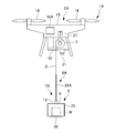
- FIG. 1 is a schematic side view showing the configuration of the unmanned aerial vehicle 1 according to the first embodiment of the present invention.
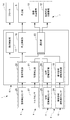
- FIG. 2 is a block diagram showing the configuration of the unmanned aerial vehicle 1 of FIG.
- the unmanned flight device 1 is held by an unmanned flying object 2, a linear member 3 hanging from the flying object 2, and a lower end of the linear member 3, and carries a cargo W inside.
- a container 4 for accommodating the container 4 and a hoisting machine 5 capable of winding the linear member 3 are provided.
- "Unmanned flight possible" means that a person can fly without a person on board the flying object, and includes not only the case where autonomous flight is possible but also the case where a person remotely controls.
- the cargo W and the container 4 may be collectively referred to as a “conveyed item T”.
- the unmanned aerial vehicle 1 has a contact detection unit 6 that detects contact of an object with the linear member 3 or the container 4, and a separation unit that separates the linear member 3 or the container 4 from the flying object 2. 7, a tension detecting unit 8 for detecting that the container 4 or the linear member 3 has been pulled, and a landing detecting unit 9 for detecting that the container 4 (conveyed object T) has landed are further provided.
- the "object" detected by the contact detection unit 6 includes humans and animals.
- the contact detection unit 6 has a configuration including a linear member contact detection unit 10 for detecting contact with at least the lower region of the linear member 3 and a container contact detection unit 11 for detecting contact with the container 4. Can be done. That is, the contact detection unit 6 may be configured to detect the contact with the linear member 3 and the contact with the conveyed object T separately.
- the separating portion 7 is a linear member separating mechanism 12 that cuts the linear member 3 in the vicinity of the flying object 2 so as to separate at least the lower region of the linear member 3, and a container separation that separates the container 4 from the linear member 3. It can be configured to have a mechanism 13.
- the air vehicle 2 is not particularly limited as long as it can fly unmanned, but the air vehicle 2 of the present embodiment shown in the figure is an unmanned rotary wing aircraft including a plurality of propellers 14. Specifically, the flying object 2 has a plurality of propellers 14 and a main body 15 that holds the plurality of propellers 14.
- the plurality of propellers 14 are held by the main body 15 and rotate to generate lift for flying the unmanned aerial vehicle 1.
- Each propeller 14 can be arranged on the upper surface of the main body 15 so that it can rotate without interfering with the main body 15. It is preferable that the plurality of propellers 14 are equidistant and equidistant from the center of the main body 15 in a plan view so that their rotation axes are in the vertical direction (rotation surface is horizontal).
- the main body 15 is configured to hold a plurality of propellers 14, a battery (power source) for driving the propellers 14 and the like, and a control device 16 for controlling the flight of the flying object 2.
- the control device 16 can be realized by having a computer device having, for example, a CPU, a memory, or the like read an appropriate program.
- the control device 16 includes a flight control unit 17 that controls the propeller, a hoisting control unit 18 that controls the hoisting machine 5, and a linear member contact determination unit 19 that constitutes a control element of the linear member contact detection unit 10.
- the container contact determination unit 20 that constitutes the control element of the container contact detection unit 11, the tension determination unit 21 that constitutes the determination control element of the tension detection unit 8, and the landing determination unit that constitutes the determination control element of the landing detection unit 9. 22 and a selection unit 23 constituting a control element of the separation unit 7 can be included.
- Each component of these control devices 16 is distinct in its function and may not be distinguishable in physical configuration or program configuration.
- the linear member 3 can be formed of, for example, a wire. Further, a linear member contact detection sensor 24 for detecting contact may be provided in the lower region of the linear member 3. The linear member contact detection sensor 24 constitutes a detection unit of the linear member contact detection unit 10 described later. The linear member 3 is also used as a signal line for transmitting signals of the container contact detection unit 11, the linear member contact detection unit 10, the container separation mechanism 13, the tension detection unit 8, and the landing detection unit 9. May be good. Therefore, the linear member 3 may be an insulated electric wire (cable).
- the container 4 can be a box body capable of accommodating any cargo W.
- the container contact detection sensor 25 that constitutes the detection unit of the container contact detection unit 11 may be arranged on the upper surface and the side surface of the container 4, and the landing that constitutes the detection unit of the landing detection unit 9 is provided on the bottom surface of the container 4.
- the detection sensor 26 may be arranged.
- the hoisting machine 5 is a winch capable of winding and rewinding (sending) the linear member 3.
- the hoisting machine 5 can improve the stability by winding the linear member 3 and bringing it into close contact with the main body 15 during high-speed flight of the unmanned aerial vehicle 1.
- the hoisting machine 5 rewinds the linear member 3 in a state where the flying object 2 is hovering in the sky, and lowers the conveyed object T to the ground.
- the hoisting machine 5 can be configured to have a torque sensor 27 for detecting the torque thereof.
- the torque sensor 27 can form a detection unit of the tension detection unit 8.
- the contact detection unit 6 includes a linear member contact detection unit 10 that detects contact with at least the lower region of the linear member 3 and a container contact detection unit 11 that detects contact with the container 4. It can be configured to have.
- the linear member contact detection unit 10 determines whether or not a person or an object has come into contact with the container 4 based on the detection signals of the linear member contact detection sensor 24 and the linear member contact detection sensor 24.
- the configuration may include a determination unit 19.
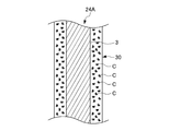
- the linear member contact detection sensor 24 for example, a pressure sensor that detects pressure, a capacitance sensor that detects a change in capacitance, or the like can be used.
- the linear member contact detection sensor 24 has a static electric member 3 having a conductive linear member 3 and a protective cover 28 made of a dielectric material arranged on the outer periphery of the linear member 3. It can be a capacitance sensor.
- the linear member contact detection sensor 24 can be configured to detect a weak current flowing through a capacitor having the linear member 3 as one electrode and the human body as the other electrode.
- the current detection circuit may be provided in the main body 15 of the flying object 2 or may be provided in the container 4.
- the linear member contact determination unit 19 determines that the linear member 3 has been contacted. Can be configured. Further, the linear member contact determination unit 19 continues to be in a state where the detection value of the linear member contact detection sensor 24 exceeds a predetermined detection threshold so as not to detect primary contact such as small dust flying in the wind. When the time exceeds a preset time threshold value, it may be determined that the linear member 3 has been contacted.
- the container contact detection unit 11 includes a container contact detection sensor 25 and a container contact determination unit 20 that determines whether or not a person or an object has come into contact with the container 4 based on the detection signal of the container contact detection sensor 25. can do.
- the container contact detection sensor 25 for example, a pressure sensor for detecting pressure, a capacitance sensor for detecting a change in capacitance, or the like can be used.
- the container contact detection sensor 25 can be a capacitance sensor having an electrode laminated on the outer surface of the container 4 and a dielectric layer laminated on the outer surface of the electrode.
- the container contact detection sensor 25 is preferably arranged on the upper surface or the side surface of the container 4, and is preferably arranged so as to cover substantially the entire upper surface and the side surface of the container 4.
- the container contact determination unit 20 has contacted the container 4 when the detection value (for example, the current value) of the container contact detection sensor 25 exceeds a preset detection threshold value. It can be configured to determine that. In addition, the container contact determination unit 20 also presets a time during which the detection value of the container contact detection sensor 25 continues to exceed a predetermined detection threshold so as not to detect primary contact such as small dust flying in the wind. It may be determined that the container 4 has been contacted when the time threshold value is exceeded.
- the separating portion 7 includes a linear member separating mechanism 12 that cuts the linear member 3 in the vicinity of the flying object 2 so as to separate at least the lower region of the linear member 3, and a container from the linear member 3. It can be configured to have a container separation mechanism 13 for separating the 4.
- the linear member separation mechanism 12 separates at least the lower region of the linear member 3 from the flying object 2 together with the container 4 (conveyed object T).
- a specific configuration of the linear member separating mechanism 12 for example, a configuration having a cutter for cutting the linear member 3 or the like is possible.
- the container separation mechanism 13 separates the container 4 from the linear member 3 and thus from the flying object 2 by separating the container 4 from the linear member 3.
- the container separation mechanism 13 may have a configuration in which a movable structure capable of engaging with and detaching from the tip end portion of the linear member 3 is provided on the container 4 side.
- the detection result of the tension detection unit 8 and the detection result of the landing detection unit are added to the line.
- the shape member separation mechanism 12 or the container separation mechanism 13 is selectively operated. Specifically, in the selection unit 23, when the linear member contact detection unit 10 detects contact with the linear member 3 during the flight of the unmanned aerial vehicle 1, and the tension detection unit 8 tensions the linear member 3. When it is detected, the linear member separation mechanism 12 is operated, and when the container contact detection unit 11 detects contact with the container 4 while the linear member contact detection unit 10 and the tension detection unit 8 have not been detected. The container separation mechanism 13 is operated. Further, when the landing detection unit 9 detects the landing, the selection unit 23 operates the container separation mechanism 13 as a normal operation for delivering the transported object T.
- the tension detection unit 8 has a torque sensor 27 and a tension determination unit 21 that determines whether or not the linear member 3 is pulled directly or via the container 4 based on the detection signal of the torque sensor 27. be able to.
- the torque sensor 27 can be configured by a strain sensor or the like that detects the twist of the shaft of the hoisting machine 5.
- the tension determination unit 21 can be configured to determine that the linear member 3 has been pulled when the detection value of the torque sensor 27 exceeds a preset threshold value.
- the landing detection unit 9 can have a landing detection sensor 26 and a landing determination unit 22 that determines whether or not the container 4 is in contact with the ground based on the detection signal of the landing detection sensor 26.
- the landing detection sensor 26 can be configured by, for example, a pressure sensor, a switch operated by the weight of the transported object T, or the like.
- the selection unit 23 When the container contact detection unit 11 detects contact, the selection unit 23 operates the container separation mechanism 13 to separate the container 4 (conveyed object T) from the linear member 3, and the linear member contact detection unit 10 When the contact is detected, the linear member separating mechanism 12 is operated to separate at least the lower region of the linear member 3 from the flying object 2 together with the conveyed object T. That is, when a person or an animal actively interferes with the linear member 3 or the container 4 or the linear member 3 or the container 4 is caught in a tree, a building, or the like, the selection unit 23 is a contact object thereof. Before (including humans and animals) exerts a large external force on the flying object 2 through the linear member 3, the flight state of the flying object 2 is changed by separating the portion in contact with the contact object from the flying object 2. Prevent instability in advance.
- the selection unit 23 operates the linear member separating mechanism 12 to fly at least the lower region of the linear member 3 together with the conveyed object T. It may be separated from body 2.
- the linear member contact detection unit 10 detects contact with the linear member 3
- the selection unit 23 operates the linear member separation mechanism 12 to separate the linear member 3.
- the tension detecting unit 8 does not detect the tension of the linear member 3.
- the tension detecting unit 8 detects the tension of the linear member 3 before the linear member 3 is separated. May be done. Further, depending on the type and state of the contact object, the type of the sensor, etc., the contact with the linear member contact detection unit 10 cannot be detected, or the linear member contact detection unit 10 fails and the linear member 3 fails. Even when the contact with the linear member cannot be detected, the tension detecting unit 8 can detect the tension of the linear member 3 prior to the linear member contact detecting unit 10. In these cases, it is conceivable to separate the linear member 3 as an emergency control.
- the selection unit 23 separates the container 4 from the linear member 3 in order to deliver the transported object T to the consignee.
- FIG. 4 shows the procedure of the method of transporting the transported object T by the unmanned aerial vehicle 1.
- the method of transporting the transported object T by the unmanned flight device 1 is a method of transporting the transported object T by the flying object 2 capable of flying unmanned, and is itself an embodiment of the transport method according to the present invention.
- the transport method of FIG. 4 includes a step of holding the transported object T at the lower end of the linear member 3 hanging from the flying object 2 (step S11: conveyed object holding step) and a step of starting the flight of the flying object 2 (step).
- S12 flight start step
- step S13 linear member contact detection step
- step S15 container contact detection step
- step S16 container separation step
- the transported object T (regardless of the presence or absence of the cargo W) is held by the flying object 2 by connecting the container 4 to the lower end of the linear member 3.
- step S12 the flight of the unmanned flight device 1 is started. Therefore, the steps after step S13 are then performed during the flight of the flying object 2. Since the flight control of the unmanned aerial vehicle 1 can be performed by a well-known method, detailed description thereof will be omitted.
- step S13 the presence or absence of contact with the linear member 3 is confirmed by the linear member contact detection unit 10.
- step S14 the process proceeds to the linear member separation step of step S14, and if contact with the linear member 3 is not confirmed, step S15 is performed. Proceed to the container contact detection step.
- step S14 the linear member 3 is cut by the linear member separation mechanism 12 to separate the lower region of the linear member 3 from the flying object 2.
- the container contact detection unit 11 confirms the presence or absence of contact with the container 4. In this container contact detection step, if contact with the container 4 is confirmed, the process proceeds to the container separation step of step S16, and if contact with the container 4 is not confirmed, the linear member contact detection step of step S13 is performed. Return.
- step S16 the container 4 (container T) is separated from the linear member 3 by the container separation mechanism 13.
- the transfer of the transported object T ends.
- the unmanned aerial vehicle 1 continues to fly according to a preset program even after the transportation of the transported object T is completed.
- the unmanned aerial vehicle 1 when an object comes into contact with the linear member 3 or the container 4, the linear member 3 or the conveyed object T is separated and tension acts on the linear member 3. Therefore, it is possible to prevent a large external force from being applied to the flying object 2. Therefore, in the unmanned aerial vehicle 1, the attitude of the flying object 2 is unlikely to become unstable.
- the cargo W is delivered in a place where there are many people, there is a risk that a third party may pull the linear member 3 or the container 4 because of interest. In such a case, the flying object 2 is pulled and the posture of the flying object 2 becomes unstable by separating the linear member 3 and the container 4 at the moment when a person touches the linear member 3 or the container 4. Can be prevented.
- FIG. 5 is a schematic side view showing the configuration of the unmanned aerial vehicle 1A according to the second embodiment of the present invention.
- FIG. 6 is a block diagram showing the configuration of the unmanned aerial vehicle 1A of FIG.
- the unmanned flight device 1A is held by an unmanned flying object 2A, a linear member 3 hanging from the flying object 2A, and a container 4 held at the lower end of the linear member 3 and accommodating the cargo W (cargo W and container). 4), the hoisting machine 5 capable of winding the linear member 3, and the contact of an object (including a person or an animal) with the linear member 3 or the container 4
- a contact detection unit 6A for detecting the above a separation unit 7A for separating the linear member 3 or the container 4 from the flying object 2A, a tension detection unit 8 for detecting that the container 4 or the linear member 3 is pulled, and a container.
- the landing detection unit 9 for detecting that the 4 has landed, and the contact object determination unit 29 for determining the type of the contact object with the linear member 3 or the container 4 are provided.
- the same components as those of the unmanned aerial vehicle 1 of the first embodiment are designated by the same reference numerals, and duplicate description will be omitted.
- the flight body 2A has a control device 16A that controls flight and constitutes control elements of a contact detection unit 6A, a separation unit 7A, a tension detection unit 8, a landing detection unit 9, and a contact object discrimination unit 29.
- the contact detection unit 6A has a configuration including a linear member contact detection unit 10A for detecting contact with at least the lower region of the linear member 3 and a container contact detection unit 11 for detecting contact with the container 4. Can be done.
- the linear member contact detection unit 10A can have a configuration including a linear member contact detection sensor 24A and a linear member contact determination unit 19.
- the linear member contact detection sensor 24A is arranged on the outer periphery of the linear member 3 and has a sensitive layer 30 in which a large number of carbon microcoils are dispersed in an insulating elastomer base material. Can be.
- the sensitive layer 30 can be electrically considered as a distributed constant circuit in which a plurality of resistors, capacitors and inductors are intricately combined. Further, when an external force is applied to the sensitive layer 30, the carbon microcoils existing in the portion are deformed and moved, so that the electrical characteristics of the sensitive layer 30 change sharply.
- the linear member contact detection unit 10A detects a change in the electrical characteristics of the sensitive layer 30 due to a minute contact pressure due to contact of an object with the linear member contact detection sensor 24A, thereby moving to the linear member 3.
- the contact of the object can be detected.
- the detection circuit may be provided in the main body 15 of the flying object 2A, or may be provided in the container 4.
- the separation unit 7A separates the linear member separation mechanism 12 that cuts the linear member 3 in the vicinity of the flying object 2A so as to separate at least the lower region of the linear member 3, and the container separation that separates the container 4 from the linear member 3. It can be configured to have a mechanism 13 and a selection unit 23A.
- the selection unit 23A includes the linear member separation mechanism 12 and the container based on the determination results of the linear member contact detection unit 10A, the container contact detection unit 11, the tension detection unit 8, the landing detection unit 9, and the contact object discrimination unit 29.
- One of the separation mechanisms 13 is selectively operated. Even when the linear member contact detection unit 10A or the container contact detection unit 11 detects contact, the selection unit 23A may include an object (which may include a small animal) having a small contact object determined by the contact object determination unit 29. If it is considered that the flight of the flying object 2 is not unstable, the linear member separating mechanism 12 and the container separating mechanism 13 may not be operated.
- the selection unit 23A operates the separation unit 7A, that is, whether the contact object discrimination unit 29 operates the contact object discrimination result and either the linear member separation mechanism 12 or the container separation mechanism 13 operates, or does not operate either of them.
- the separation unit 7A may be operated by referring to the correspondence table in which the correspondence of the above is described.
- the contact object discriminating unit 29 is held by the flying object 2A and determines the type of the contact object to the linear member 3 or the container 4 based on the camera 31 that captures the lower part and the image captured by the camera 31. It can be configured to have a portion 32. As an example, the contact object discriminating unit 29 can be configured to discriminate the type of contact object based on the size and shape of the contact object in the captured image.
- the unmanned aerial vehicle 1A can more appropriately separate the transported object T and prevent the flight of the flying object 2A from becoming unstable by providing the contact object discriminating unit 29.
- each embodiment of the present invention exerts an advantageous effect by each of the following configurations.
- the unmanned flight device (1,1A) holds an unmanned flying object (2,2A) and a carrier (T: container 4 and cargo W) hanging from the flying object (2,2A) at the lower end.
- a separation unit (7, 7A) for separating the transported object (T) or the linear member (3) based on the result is provided.
- the conveyed object (T) or the linear member (3) is moved to the flying object (2,2A) before the contact object exerts a large external force on the flying object (2,2A) through the linear member (3).
- By separating from) it is possible to prevent the flight state of the flying object (2, 2A) from becoming unstable in advance.
- the separation unit (7A) has a selection unit (23A) that selects whether to separate only the transported object (T) or the linear member (3) together with the transported object (T). Have. Thereby, the unmanned aerial vehicle (1A) can more appropriately separate the transported object (T) and prevent the flight of the flying object (2A) from becoming unstable.
- the unmanned aerial vehicle (1A) further includes a contact object determination unit (29) for determining the type of contact object for which the contact detection unit (6A) has detected contact, and the separation unit (7A) corresponds to the type of contact object. Then, it is selected whether to separate only the transported object (T) or the linear member (3) together with the transported object (T). Thereby, the unmanned aerial vehicle (1A) can separate the transported object (T) only when necessary to prevent the flight of the flying object (2A) from becoming unstable.
- the contact detection unit (6) distinguishes between the contact with the conveyed object (T) and the contact with the linear member (3), and the separation unit (7A) determines. Depending on the type of contact object, it is selected whether to separate only the conveyed object (T) or the linear member (3) together with the conveyed object (T). Thereby, the unmanned aerial vehicle (1,1A) can separate the transported object (T) only when necessary to prevent the flight of the flying object (2A) from becoming unstable.
- the contact detection unit (6,6A) detects contact with the upper surface or side surface of the transported object (T). As a result, it is possible to detect a contact in a mode in which an external force acts on the transported object (T) and the flying object (2, 2A) is likely to be pulled.
- the unmanned aerial vehicle (1,1A) further includes a tension detection unit (8) for detecting that the transported object (T) or the linear member (3) has been pulled, and the separation unit (7,7A) is tensioned.
- the transported object (T) or the linear member (3) is separated in consideration of the detection result of the detection unit (8). That is, the separation unit (7,7A) includes a container separation mechanism 13 for separating the transported object (T), a linear member separation mechanism (12) for separating the linear member (3), and a contact detection unit (6,6A). ) And the selection unit (23) for operating either the container separation mechanism (13) or the linear member separation mechanism (12) based on the detection result of the tension detection unit (8).
- the contact detection unit (6, 6A) the conveyed object (T) or the linear member (3) is separated and the flying object (2, 2A) is separated.
- the unmanned aerial vehicle (1,1A) further includes a landing detection unit (9) for detecting that the transported object has landed, and the separation unit (7,7A) takes into account the detection result of the landing detection unit (9).
- the transported object (T) or the linear member (3) is separated. As a result, the transported object (T) can be delivered without dropping during normal transport.
- the transported object (T) is held at the lower end of the linear member (3) and includes a container (4) for accommodating the cargo (W) inside. This facilitates the detection of contact with the transported object (T) by the contact detection unit (6).
- the contact detection unit (6,6A) includes a contact detection sensor (24,24A) that detects contact of the linear member (3) with at least the lower region. As a result, contact with the linear member (3) can be reliably detected.
- the contact detection sensor (24) is a capacitance sensor that detects a change in capacitance. As a result, contact with the linear member (3) can be detected relatively easily.
- the contact detection sensor (24A) includes a carbon microcoil. Thereby, the contact with the linear member (3) can be detected in detail.
- the method of transporting the transported object (T) by the flying object (2) capable of flying unmanned is a step of holding the transported object (T) at the lower end of the linear member (3) hanging from the flying object (2).
- the conveyed object (T) or wire based on the detection results in the step of detecting the contact with the conveyed object (T) or the linear member (3) during the flight of the flying object (2) and the step of detecting the contact.
- a step of separating the shaped member (3) is provided.
- the flying object is not limited to the unmanned rotary wing aircraft, and may be, for example, an unmanned airship.
- the transported object may be any device, for example, an arbitrary device such as a camera or a sensor.
- the transported object does not include a container, and the cargo or the like may be directly held at the lower end of the linear member by using, for example, a binding band or the like.
- the unmanned aerial vehicle of the present invention may not include a hoisting machine, and the upper end of the linear member may be connected to the flying object.
- the contact detection unit of the unmanned aerial vehicle detects contact with at least one of the linear member and the container, for example, a configuration having only one of the linear member contact detection unit and the container contact detection unit. Anything that can be done will do.
- the contact detection unit may be configured to have an image contact detection unit that determines the presence or absence of contact with the linear member or the conveyed object based on the image taken by the camera. Such an image contact detection unit may be used alone or in combination with a detection unit that uses a contact detection sensor such as a linear member contact detection unit and a container contact detection unit.
- the tension detection unit and the landing detection unit may be omitted.
- the separating portion of the unmanned aerial vehicle according to the embodiment of the present invention may have at least one of a container separating mechanism and a linear member separating mechanism.
- the separating portion preferably includes a linear member separating mechanism.
- the configuration of the linear member contact detection sensor is not limited to the configuration of the above-described embodiment, and any configuration can detect the contact of an object. You may.
- the electrode of the linear member contact detection sensor may be a conductor layer arranged on the outer periphery of the linear member. Further, the linear member contact detection sensor may have an electrode on the outer peripheral side as well.
- the type determination unit in the unmanned aerial vehicle may be configured to determine the type of the contact object based on the information of a sensor other than the camera.
- the type determination unit may have a three-dimensional distance sensor or the like.
- the type determination unit may be integrally configured with the contact detection unit.
- the contact detection unit has a contact detection sensor including a carbon microcoil
- the contact is detected by storing the relationship between the change tendency of the electrical characteristics of the sensitive layer and the type of the contact object in advance. At the same time, the type of contact can be determined.
- the components related to the control of the contact detection unit, the separation unit, the tension detection unit, and the landing detection unit are realized by the control device housed in the main body. At least a part of the constituent elements according to the above may be independently configured, or may be attached to or incorporated in a physical component such as a sensor or a separation mechanism.
- Selection unit, 24 , 24A ... Linear member contact detection sensor, 25 ... Container contact detection sensor, 26 ... Landing detection sensor, 27 ... Torque sensor, 28 ... Protective cover, 29 ... Contact object discrimination Department, 30 ... Sensitive layer, 31 ... Camera, 32 ... Type determination unit, C ... Carbon microcoil, T ... Transport, W ... Freight
Abstract
The purpose of the present invention is to provide an unmanned flight device such that, when there is an abnormality in the flight body, the abnormality can be quickly reported to a person below. An unmanned flight device 1 according to the present invention comprises: a flight body 2 that can fly unmanned; a linear member 3 suspended from the flight body 2 that holds, at a bottom end, a transport object T; a contact detection unit 6 that detects contact with the transport object T or the linear member 3; and a separation unit 7 that separates the transport object T or the linear member 3 on the basis of the detection result of the contact detection unit 6.
Description
本発明は無人飛行装置及び搬送方法に関する。
The present invention relates to an unmanned aerial vehicle and a transport method.
所謂ドローン等の無人で飛行可能な飛行体を利用して貨物を運搬することが検討されている。飛行体に貨物を収容するボックス等を付設し、飛行体が着地した状態でボックスを開放して貨物を引き渡すことが行われている。この場合、貨物の受け渡し場所として、飛行体が着地可能な一定以上の面積を有する平坦な場所が必用となる。
It is being considered to transport cargo using an unmanned flying object such as a so-called drone. A box or the like for accommodating cargo is attached to the air vehicle, and the box is opened and the cargo is delivered while the air vehicle has landed. In this case, a flat place having a certain area or more on which the flying object can land is required as a cargo delivery place.
そこで、例えば下記特許文献1、2に記載されるように、飛行体から垂下されるワイヤや紐等の線状部材の下端に搬送物(貨物及び貨物を収容する容器を含み得る)を保持させ、飛行体が着地することなく、空中に留まったまま貨物を引き渡すことも検討されている。このような方法によれば、搬送物を載置できる比較的小さいスペースがあれば、貨物を引き渡すことができる。
Therefore, for example, as described in Patent Documents 1 and 2 below, a transported object (including cargo and a container for accommodating cargo) is held at the lower end of a linear member such as a wire or a string hanging from an air vehicle. It is also being considered to deliver cargo while it remains in the air without the aircraft landing. According to such a method, the cargo can be delivered if there is a relatively small space in which the cargo can be placed.
飛行体から垂下される線状部材によって搬送物を保持する場合、搬送物又は線状部材に風等の外力が作用して飛行体の飛行状態が不安定になる可能性がある。このため、特許文献1に記載の無人飛行装置は、飛行体の本体部に紐状部材を固定する固定装置に、貨物を吊り下げた紐状部材の鉛直線の延長線上に本体部の重心が位置するように、本体部の姿勢に応じて、紐状部材の固定態様を調整する調整手段が設けられている。これによって、特許文献1に記載の無人飛行装置は、貨物の荷重が常に飛行体の重心に作用するため、安定した飛行が可能となるとされている。
When the transported object is held by a linear member hanging from the flying object, the flight state of the flying object may become unstable due to an external force such as wind acting on the transported object or the linear member. Therefore, in the unmanned aerial vehicle described in Patent Document 1, the center of gravity of the main body is placed on the extension of the vertical line of the string-shaped member that suspends the cargo to the fixing device that fixes the string-shaped member to the main body of the flying object. An adjusting means for adjusting the fixing mode of the string-shaped member is provided so as to be positioned according to the posture of the main body. As a result, the unmanned aerial vehicle described in Patent Document 1 is said to be capable of stable flight because the load of cargo always acts on the center of gravity of the flying object.
また、特許文献2に記載の運搬装置は、無人航空機と、無人航空機の本体から垂下される主ワイヤと、主ワイヤの自由端から固定端側に入った位置で、主ワイヤに結合され、主ワイヤに沿って主ワイヤの自由端よりも外側まで延出した補助ワイヤと、を有する構成とされている。この運搬装置では、補助ワイヤが弛んだ状態で補助ワイヤの先端に貨物を取り付けることにより、貨物の取り付け作業時に作業者が主ワイヤを引っ張って無人航空機の姿勢を不安定化させることを防止できるとされている。
Further, the transport device described in Patent Document 2 is connected to the unmanned aerial vehicle, the main wire hanging from the main body of the unmanned aerial vehicle, and the main wire at a position where the main wire is entered from the free end to the fixed end side. It is configured to have an auxiliary wire extending along the wire to the outside of the free end of the main wire. In this transport device, by attaching the cargo to the tip of the auxiliary wire while the auxiliary wire is loose, it is possible to prevent the operator from pulling the main wire and destabilizing the attitude of the unmanned aerial vehicle during the cargo installation work. Has been done.
特許文献1に記載の構成では、例えば紐状部材が引っ張られるような場合には、飛行体の姿勢を保つことができないおそれがある。また、特許文献2に記載の構成では、貨物を取り付ける際に主ワイヤが引っ張られないようにできるが、貨物を受け渡す際(補助ワイヤから貨物を取り外す際)には、主ワイヤが引っ張られて無人航空機の姿勢が不安定になることを防止できない。
With the configuration described in Patent Document 1, for example, when a string-shaped member is pulled, the attitude of the flying object may not be maintained. Further, in the configuration described in Patent Document 2, the main wire can be prevented from being pulled when the cargo is attached, but the main wire is pulled when the cargo is delivered (when the cargo is removed from the auxiliary wire). It is not possible to prevent the attitude of the unmanned aerial vehicle from becoming unstable.
本発明は、このような状況に鑑みてなされたものであり、飛行体から垂下される線状部材や搬送物に作用する外力によって飛行体の姿勢が不安定になりにくい無人飛行装置を提供することを目的とする。
The present invention has been made in view of such a situation, and provides an unmanned flight device in which the attitude of the flying object is less likely to become unstable due to an external force acting on a linear member hanging from the flying object or a transported object. The purpose is.
本発明の一態様の無人飛行装置は、無人で飛行可能な飛行体と、前記飛行体から垂下され、下端に搬送物を保持する線状部材と、前記搬送物又は前記線状部材への接触を検出する接触検出部と、前記接触検出部の検出結果に基づいて前記搬送物又は前記線状部材を分離する分離部と、を備える。
The unmanned aerial vehicle according to one aspect of the present invention is a contact between an unmanned flying object, a linear member hanging from the flying object and holding an object at the lower end, and the conveyed object or the linear member. A contact detection unit for detecting the above, and a separation unit for separating the transported object or the linear member based on the detection result of the contact detection unit.
本発明の別の態様の搬送方法は、無人で飛行可能な飛行体によって搬送物を搬送する方法であって、前記飛行体から垂下される線状部材の下端に搬送物を保持させる工程と、前記飛行体の飛行中に、前記搬送物又は前記線状部材への接触を検出する工程と、前記接触を検出する工程における検出結果に基づいて前記搬送物又は前記線状部材を分離する工程と、を備える。
Another method of transporting the present invention is a method of transporting a transported object by an unmanned flying object, which comprises a step of holding the transported object at the lower end of a linear member hanging from the flying object. A step of detecting contact with the transported object or the linear member during the flight of the flying object, and a step of separating the transported object or the linear member based on the detection result in the step of detecting the contact. , Equipped with.
本発明によれば、飛行体から垂下される線状部材や搬送物に作用する外力によって飛行体の姿勢が不安定になりにくい無人飛行装置を提供することができる。
According to the present invention, it is possible to provide an unmanned aerial vehicle in which the attitude of the air vehicle is less likely to become unstable due to an external force acting on a linear member hanging from the air vehicle or a transported object.
以下、本発明の限定的ではない例示的な実施形態について、図面を参照しながら説明をする。図1は、本発明の第1実施形態に係る無人飛行装置1の構成を示す模式側面図である。図2は、図1の無人飛行装置1の構成を示すブロック図である。
Hereinafter, a non-limiting exemplary embodiment of the present invention will be described with reference to the drawings. FIG. 1 is a schematic side view showing the configuration of the unmanned aerial vehicle 1 according to the first embodiment of the present invention. FIG. 2 is a block diagram showing the configuration of the unmanned aerial vehicle 1 of FIG.
図1に示すように、無人飛行装置1は、無人で飛行可能な飛行体2と、飛行体2から垂下される線状部材3、線状部材3の下端に保持され、内部に貨物Wを収容する容器4と、線状部材3を巻き取り可能な巻上機5と、を備える。「無人で飛行可能」とは、飛行体に人が搭乗しない状態で飛行できることを意味し、自律飛行可能である場合だけでなく、人が遠隔操縦するものを含む。また、貨物Wと容器4を合わせて「搬送物T」ということがある。
As shown in FIG. 1, the unmanned flight device 1 is held by an unmanned flying object 2, a linear member 3 hanging from the flying object 2, and a lower end of the linear member 3, and carries a cargo W inside. A container 4 for accommodating the container 4 and a hoisting machine 5 capable of winding the linear member 3 are provided. "Unmanned flight possible" means that a person can fly without a person on board the flying object, and includes not only the case where autonomous flight is possible but also the case where a person remotely controls. Further, the cargo W and the container 4 may be collectively referred to as a “conveyed item T”.
図2に示すように、無人飛行装置1は、線状部材3又は容器4への物体の接触を検出する接触検出部6と、飛行体2から線状部材3又は容器4を分離する分離部7と、容器4又は線状部材3が引っ張られたことを検出する引張検出部8と、容器4(搬送物T)が着地したことを検出する着地検出部9と、をさらに備える。接触検出部6が検出する「物体」には人や動物が含まれる。
As shown in FIG. 2, the unmanned aerial vehicle 1 has a contact detection unit 6 that detects contact of an object with the linear member 3 or the container 4, and a separation unit that separates the linear member 3 or the container 4 from the flying object 2. 7, a tension detecting unit 8 for detecting that the container 4 or the linear member 3 has been pulled, and a landing detecting unit 9 for detecting that the container 4 (conveyed object T) has landed are further provided. The "object" detected by the contact detection unit 6 includes humans and animals.
接触検出部6は、線状部材3の少なくとも下側領域への接触を検出する線状部材接触検出部10と、容器4への接触を検出する容器接触検出部11とを有する構成とすることができる。つまり、接触検出部6は、線状部材3への接触と搬送物Tへの接触とを区別して検出するよう構成されてもよい。分離部7は、線状部材3の少なくとも下側領域を分離するよう線状部材3を飛行体2の近傍で切断する線状部材分離機構12と、線状部材3から容器4を切り離す容器分離機構13とを有する構成とすることができる。
The contact detection unit 6 has a configuration including a linear member contact detection unit 10 for detecting contact with at least the lower region of the linear member 3 and a container contact detection unit 11 for detecting contact with the container 4. Can be done. That is, the contact detection unit 6 may be configured to detect the contact with the linear member 3 and the contact with the conveyed object T separately. The separating portion 7 is a linear member separating mechanism 12 that cuts the linear member 3 in the vicinity of the flying object 2 so as to separate at least the lower region of the linear member 3, and a container separation that separates the container 4 from the linear member 3. It can be configured to have a mechanism 13.
以下、無人飛行装置1の各構成について説明する。まず、飛行体2について説明する。飛行体2は、無人で飛行可能なものであれば特に限定されないが、図示する本実施形態の飛行体2は、複数のプロペラ14を備える無人回転翼機である。具体的には、飛行体2は、複数のプロペラ14と、複数のプロペラ14を保持する本体15とを有する。
Hereinafter, each configuration of the unmanned aerial vehicle 1 will be described. First, the flying object 2 will be described. The air vehicle 2 is not particularly limited as long as it can fly unmanned, but the air vehicle 2 of the present embodiment shown in the figure is an unmanned rotary wing aircraft including a plurality of propellers 14. Specifically, the flying object 2 has a plurality of propellers 14 and a main body 15 that holds the plurality of propellers 14.
複数のプロペラ14は、本体15に保持され、回転することによって無人飛行装置1を飛行させるための揚力を発生させる。各プロペラ14は、本体15に干渉せずに回転することができるよう、本体15の上面に配設することができる。複数のプロペラ14は、その回転軸が鉛直方向(回転面が水平)となるよう、平面視で本体15の中心から等距離且つ等間隔に保持されることが好ましい。
The plurality of propellers 14 are held by the main body 15 and rotate to generate lift for flying the unmanned aerial vehicle 1. Each propeller 14 can be arranged on the upper surface of the main body 15 so that it can rotate without interfering with the main body 15. It is preferable that the plurality of propellers 14 are equidistant and equidistant from the center of the main body 15 in a plan view so that their rotation axes are in the vertical direction (rotation surface is horizontal).
本体15は、複数のプロペラ14を保持するとともに、プロペラ14等を駆動するためのバッテリ(電源)と、飛行体2の飛行等を制御する制御装置16と、を収容するよう構成される。
The main body 15 is configured to hold a plurality of propellers 14, a battery (power source) for driving the propellers 14 and the like, and a control device 16 for controlling the flight of the flying object 2.
制御装置16は、例えばCPU、メモリ等を有するコンピュータ装置に、適切なプログラムを読み込ませることで実現することができる。制御装置16は、プロペラを制御する飛行制御部17と、巻上機5を制御する巻上制御部18と、線状部材接触検出部10の制御要素を構成する線状部材接触判定部19と、容器接触検出部11の制御要素を構成する容器接触判定部20と、引張検出部8の判定制御要素を構成する引張判定部21と、着地検出部9の判定制御要素を構成する着地判定部22と、分離部7の制御要素を構成する選択部23と、を含むことができる。これらの制御装置16の各構成要素は、その機能において区別されるものであり、物理的な構成やプログラムの構成において区別できるものでなくてもよい。
The control device 16 can be realized by having a computer device having, for example, a CPU, a memory, or the like read an appropriate program. The control device 16 includes a flight control unit 17 that controls the propeller, a hoisting control unit 18 that controls the hoisting machine 5, and a linear member contact determination unit 19 that constitutes a control element of the linear member contact detection unit 10. , The container contact determination unit 20 that constitutes the control element of the container contact detection unit 11, the tension determination unit 21 that constitutes the determination control element of the tension detection unit 8, and the landing determination unit that constitutes the determination control element of the landing detection unit 9. 22 and a selection unit 23 constituting a control element of the separation unit 7 can be included. Each component of these control devices 16 is distinct in its function and may not be distinguishable in physical configuration or program configuration.
線状部材3は、例えばワイヤによって構成することができる。また、線状部材3の下側領域には、接触を検出する線状部材接触検出センサ24が設けられてもよい。この線状部材接触検出センサ24は、後述する線状部材接触検出部10の検出部を構成する。また、線状部材3は、容器接触検出部11、線状部材接触検出部10、容器分離機構13、引張検出部8及び着地検出部9の信号を伝達するための信号線としても利用されてもよい。このため、線状部材3は、絶縁電線(ケーブル)であってもよい。
The linear member 3 can be formed of, for example, a wire. Further, a linear member contact detection sensor 24 for detecting contact may be provided in the lower region of the linear member 3. The linear member contact detection sensor 24 constitutes a detection unit of the linear member contact detection unit 10 described later. The linear member 3 is also used as a signal line for transmitting signals of the container contact detection unit 11, the linear member contact detection unit 10, the container separation mechanism 13, the tension detection unit 8, and the landing detection unit 9. May be good. Therefore, the linear member 3 may be an insulated electric wire (cable).
容器4は、任意の貨物Wを収容可能な箱体とすることができる。容器4の上面及び側面には、容器接触検出部11の検出部を構成する容器接触検出センサ25が配設されてもよく、容器4の底面には着地検出部9の検出部を構成する着地検出センサ26が配設されてもよい。
The container 4 can be a box body capable of accommodating any cargo W. The container contact detection sensor 25 that constitutes the detection unit of the container contact detection unit 11 may be arranged on the upper surface and the side surface of the container 4, and the landing that constitutes the detection unit of the landing detection unit 9 is provided on the bottom surface of the container 4. The detection sensor 26 may be arranged.
巻上機5は、線状部材3を巻き取り及び巻き戻し(送出)することができるウインチである。巻上機5は、無人飛行装置1の高速飛行時には線状部材3を巻き取って本体15に密着させることにより安定性を向上させることができる。巻上機5は、飛行体2が上空にホバリングした状態で、線状部材3を巻き戻して搬送物Tを地上に降下させる。
The hoisting machine 5 is a winch capable of winding and rewinding (sending) the linear member 3. The hoisting machine 5 can improve the stability by winding the linear member 3 and bringing it into close contact with the main body 15 during high-speed flight of the unmanned aerial vehicle 1. The hoisting machine 5 rewinds the linear member 3 in a state where the flying object 2 is hovering in the sky, and lowers the conveyed object T to the ground.
また、巻上機5は、そのトルクを検出するトルクセンサ27を有する構成とすることができる。トルクセンサ27は、引張検出部8の検出部を構成することができる。
Further, the hoisting machine 5 can be configured to have a torque sensor 27 for detecting the torque thereof. The torque sensor 27 can form a detection unit of the tension detection unit 8.
接触検出部6は、上述のように、線状部材3の少なくとも下側領域への接触を検出する線状部材接触検出部10と、容器4への接触を検出する容器接触検出部11とを有する構成とすることができる。
As described above, the contact detection unit 6 includes a linear member contact detection unit 10 that detects contact with at least the lower region of the linear member 3 and a container contact detection unit 11 that detects contact with the container 4. It can be configured to have.
線状部材接触検出部10は、線状部材接触検出センサ24と、線状部材接触検出センサ24の検出信号に基づいて容器4に人や物が接触したか否かを判定する線状部材接触判定部19とを有する構成とすることができる。
The linear member contact detection unit 10 determines whether or not a person or an object has come into contact with the container 4 based on the detection signals of the linear member contact detection sensor 24 and the linear member contact detection sensor 24. The configuration may include a determination unit 19.
線状部材接触検出センサ24としては、例えば圧力を検出する圧力センサ、静電容量の変化を検出する静電容量センサ等を用いることができる。例えば、線状部材接触検出センサ24は、図3に示すように、導電性を有する線状部材3と、線状部材3の外周に配設される誘電体からなる保護カバー28とを有する静電容量センサとすることができる。この線状部材接触検出センサ24は、線状部材3を一方の電極とし、人体を他方の電極とするキャパシタに流れる微弱な電流を検出するよう構成することができる。電流検出回路は、飛行体2の本体15に設けられてもよく、容器4に設けられてもよい。
As the linear member contact detection sensor 24, for example, a pressure sensor that detects pressure, a capacitance sensor that detects a change in capacitance, or the like can be used. For example, as shown in FIG. 3, the linear member contact detection sensor 24 has a static electric member 3 having a conductive linear member 3 and a protective cover 28 made of a dielectric material arranged on the outer periphery of the linear member 3. It can be a capacitance sensor. The linear member contact detection sensor 24 can be configured to detect a weak current flowing through a capacitor having the linear member 3 as one electrode and the human body as the other electrode. The current detection circuit may be provided in the main body 15 of the flying object 2 or may be provided in the container 4.
線状部材接触判定部19は、線状部材接触検出センサ24の検出値(例えば電流値)が予め設定される演出閾値を超える場合に線状部材3への接触があったものと判定するよう構成することができる。また、線状部材接触判定部19は、風に舞っている小さなごみ等の一次的な接触を検出しないよう、線状部材接触検出センサ24の検出値が所定の検出閾値を超える状態が継続する時間が予め設定される時間閾値以上となった場合に線状部材3への接触があったものと判定してもよい。
When the detection value (for example, the current value) of the linear member contact detection sensor 24 exceeds a preset effect threshold value, the linear member contact determination unit 19 determines that the linear member 3 has been contacted. Can be configured. Further, the linear member contact determination unit 19 continues to be in a state where the detection value of the linear member contact detection sensor 24 exceeds a predetermined detection threshold so as not to detect primary contact such as small dust flying in the wind. When the time exceeds a preset time threshold value, it may be determined that the linear member 3 has been contacted.
容器接触検出部11は、容器接触検出センサ25と、容器接触検出センサ25の検出信号に基づいて容器4に人や物が接触したか否かを判定する容器接触判定部20とを有する構成とすることができる。
The container contact detection unit 11 includes a container contact detection sensor 25 and a container contact determination unit 20 that determines whether or not a person or an object has come into contact with the container 4 based on the detection signal of the container contact detection sensor 25. can do.
容器接触検出センサ25は、例えば圧力を検出する圧力センサ、静電容量の変化を検出する静電容量センサ等を用いることができる。具体例として、容器接触検出センサ25は、容器4の外面に積層される電極と、電極の外面に積層される誘電体層とを有する静電容量センサとすることができる。また、容器接触検出センサ25は、容器4の上面又は側面に配設されることが好ましく、容器4の上面及び側面の略全体を覆うよう配設されることが好ましい。
As the container contact detection sensor 25, for example, a pressure sensor for detecting pressure, a capacitance sensor for detecting a change in capacitance, or the like can be used. As a specific example, the container contact detection sensor 25 can be a capacitance sensor having an electrode laminated on the outer surface of the container 4 and a dielectric layer laminated on the outer surface of the electrode. Further, the container contact detection sensor 25 is preferably arranged on the upper surface or the side surface of the container 4, and is preferably arranged so as to cover substantially the entire upper surface and the side surface of the container 4.
容器接触判定部20は、線状部材接触判定部19と同様に、容器接触検出センサ25の検出値(例えば電流値)が予め設定される検出閾値を超える場合に容器4への接触があったものと判定するよう構成することができる。また、容器接触判定部20も、風に舞っている小さなごみ等の一次的な接触を検出しないよう、容器接触検出センサ25の検出値が所定の検出閾値を超える状態が継続する時間が予め設定される時間閾値以上となった場合に容器4への接触があったものと判定してもよい。
Similar to the linear member contact determination unit 19, the container contact determination unit 20 has contacted the container 4 when the detection value (for example, the current value) of the container contact detection sensor 25 exceeds a preset detection threshold value. It can be configured to determine that. In addition, the container contact determination unit 20 also presets a time during which the detection value of the container contact detection sensor 25 continues to exceed a predetermined detection threshold so as not to detect primary contact such as small dust flying in the wind. It may be determined that the container 4 has been contacted when the time threshold value is exceeded.
分離部7は、上述のように、線状部材3の少なくとも下側領域を分離するよう線状部材3を飛行体2の近傍で切断する線状部材分離機構12と、線状部材3から容器4を切り離す容器分離機構13とを有する構成とすることができる。
As described above, the separating portion 7 includes a linear member separating mechanism 12 that cuts the linear member 3 in the vicinity of the flying object 2 so as to separate at least the lower region of the linear member 3, and a container from the linear member 3. It can be configured to have a container separation mechanism 13 for separating the 4.
線状部材分離機構12は、線状部材3の少なくとも下側領域を切り離して容器4(搬送物T)とともに飛行体2から分離する。具体的な線状部材分離機構12の構成としては、例として、線状部材3を切断するカッタを有する構成等が可能である。
The linear member separation mechanism 12 separates at least the lower region of the linear member 3 from the flying object 2 together with the container 4 (conveyed object T). As a specific configuration of the linear member separating mechanism 12, for example, a configuration having a cutter for cutting the linear member 3 or the like is possible.
容器分離機構13は、線状部材3から容器4を切り離すことにより、容器4を線状部材3ひいては飛行体2から搬送物Tを分離する。具体的な容器分離機構13の構成としては、例として、容器4の頂部に設けられる吊環と、線状部材3の下端に設けられ、吊環に係合する開閉可能なフックとを有する構成、容器4の頂部の開口に嵌合する挿入部と、挿入部の先端に突退可能に設けられる係止爪とを有する構成等が可能である。また、容器分離機構13は、容器4側に、線状部材3の先端部と係合及び脱離可能な可動構造を設けた構成としてもよい。
The container separation mechanism 13 separates the container 4 from the linear member 3 and thus from the flying object 2 by separating the container 4 from the linear member 3. As a specific configuration of the container separation mechanism 13, for example, a container having a suspension ring provided at the top of the container 4 and an openable / closable hook provided at the lower end of the linear member 3 and engaged with the suspension ring. It is possible to have a configuration having an insertion portion that fits into the opening at the top of 4 and a locking claw that is provided at the tip of the insertion portion so as to be retractable. Further, the container separation mechanism 13 may have a configuration in which a movable structure capable of engaging with and detaching from the tip end portion of the linear member 3 is provided on the container 4 side.
選択部23は、接触検出部6の線状部材接触検出部10及び容器接触検出部11の検出結果に加えて、引張検出部8の検出結果及び着地検出部の検出結果を加味して、線状部材分離機構12又は容器分離機構13を選択的に動作させる。具体的には、選択部23は、無人飛行装置1の飛行中に線状部材接触検出部10が線状部材3への接触を検出した場合及び引張検出部8が線状部材3の引張を検出した場合には線状部材分離機構12を動作させ、線状部材接触検出部10及び引張検出部8が未検出の状態で容器接触検出部11が容器4への接触を検出した場合には容器分離機構13を動作させる。また、選択部23は、着地検出部9が着地を検出した場合には、搬送物Tを受け渡すための通常の動作として、容器分離機構13を動作させる。
In the selection unit 23, in addition to the detection results of the linear member contact detection unit 10 and the container contact detection unit 11 of the contact detection unit 6, the detection result of the tension detection unit 8 and the detection result of the landing detection unit are added to the line. The shape member separation mechanism 12 or the container separation mechanism 13 is selectively operated. Specifically, in the selection unit 23, when the linear member contact detection unit 10 detects contact with the linear member 3 during the flight of the unmanned aerial vehicle 1, and the tension detection unit 8 tensions the linear member 3. When it is detected, the linear member separation mechanism 12 is operated, and when the container contact detection unit 11 detects contact with the container 4 while the linear member contact detection unit 10 and the tension detection unit 8 have not been detected. The container separation mechanism 13 is operated. Further, when the landing detection unit 9 detects the landing, the selection unit 23 operates the container separation mechanism 13 as a normal operation for delivering the transported object T.
引張検出部8は、トルクセンサ27と、トルクセンサ27の検出信号に基づいて線状部材3が直接又は容器4を介して引っ張られたか否かを判定する引張判定部21とを有する構成とすることができる。
The tension detection unit 8 has a torque sensor 27 and a tension determination unit 21 that determines whether or not the linear member 3 is pulled directly or via the container 4 based on the detection signal of the torque sensor 27. be able to.
トルクセンサ27は、巻上機5のシャフトのねじれを検出する歪センサ等によって構成することができる。
The torque sensor 27 can be configured by a strain sensor or the like that detects the twist of the shaft of the hoisting machine 5.
引張判定部21は、トルクセンサ27の検出値が予め設定される閾値を超える場合に線状部材3が引っ張られたと判定するよう構成することができる。
The tension determination unit 21 can be configured to determine that the linear member 3 has been pulled when the detection value of the torque sensor 27 exceeds a preset threshold value.
着地検出部9は、着地検出センサ26と、着地検出センサ26の検出信号に基づいて容器4が地面に当接しているか否かを判定する着地判定部22とを有する構成とすることができる。
The landing detection unit 9 can have a landing detection sensor 26 and a landing determination unit 22 that determines whether or not the container 4 is in contact with the ground based on the detection signal of the landing detection sensor 26.
着地検出センサ26は、例えば、圧力センサ、搬送物Tの重量により作動するスイッチ等によって構成することができる。
The landing detection sensor 26 can be configured by, for example, a pressure sensor, a switch operated by the weight of the transported object T, or the like.
選択部23は、容器接触検出部11が接触を検出した場合には、容器分離機構13を動作させて容器4(搬送物T)を線状部材3から分離し、線状部材接触検出部10が接触を検出した場合には線状部材分離機構12を動作させて線状部材3の少なくとも下側領域を搬送物Tとともに飛行体2から分離する。つまり、選択部23は、人や動物が線状部材3や容器4に能動的に干渉したり、線状部材3や容器4が樹木や建造物等に引っ掛かったりした場合に、これらの接触物(人や動物を含む)が線状部材3を介して飛行体2に大きな外力を作用させる前に、接触物が接触した部分を飛行体2から分離することによって、飛行体2の飛行状態が不安定になることを事前に防止する。
When the container contact detection unit 11 detects contact, the selection unit 23 operates the container separation mechanism 13 to separate the container 4 (conveyed object T) from the linear member 3, and the linear member contact detection unit 10 When the contact is detected, the linear member separating mechanism 12 is operated to separate at least the lower region of the linear member 3 from the flying object 2 together with the conveyed object T. That is, when a person or an animal actively interferes with the linear member 3 or the container 4 or the linear member 3 or the container 4 is caught in a tree, a building, or the like, the selection unit 23 is a contact object thereof. Before (including humans and animals) exerts a large external force on the flying object 2 through the linear member 3, the flight state of the flying object 2 is changed by separating the portion in contact with the contact object from the flying object 2. Prevent instability in advance.
また、選択部23は、引張検出部8が線状部材3の引張を検出した場合には、線状部材分離機構12を動作させて線状部材3の少なくとも下側領域を搬送物Tとともに飛行体2から分離してもよい。上述したように、線状部材接触検出部10が線状部材3への接触を検出した場合、選択部23が線状部材分離機構12を動作させて線状部材3を分離する。ここで、線状部材3に張力が作用する前に線状部材3が分離されれば、引張検出部8が線状部材3の引張を検出することはない。しかし、接触の検出から線状部材3の分離までの間には、処理や線状部材分離機構12の駆動等にかかる時間的遅れ(ラグ)が生じる。そのため、接触物が線状部材3に引張を作用させる速度によっては(例えば速度が非常に速ければ)、線状部材3が分離される前に引張検出部8が線状部材3の引張を検出する場合がある。また、接触物の種別や状態、センサの種別等によって、線状部材接触検出部10線状部材3への接触を検出できない場合や、線状部材接触検出部10が故障して線状部材3への接触を検出できない場合にも、線状部材接触検出部10に先んじて引張検出部8が線状部材3の引張を検出し得る。これらの場合には、非常的な制御として、線状部材3の分離を行うことが考えられる。
Further, when the tension detecting unit 8 detects the tension of the linear member 3, the selection unit 23 operates the linear member separating mechanism 12 to fly at least the lower region of the linear member 3 together with the conveyed object T. It may be separated from body 2. As described above, when the linear member contact detection unit 10 detects contact with the linear member 3, the selection unit 23 operates the linear member separation mechanism 12 to separate the linear member 3. Here, if the linear member 3 is separated before the tension acts on the linear member 3, the tension detecting unit 8 does not detect the tension of the linear member 3. However, between the detection of contact and the separation of the linear member 3, there is a time delay (lag) required for processing, driving the linear member separating mechanism 12, and the like. Therefore, depending on the speed at which the contact object exerts tension on the linear member 3 (for example, if the speed is very high), the tension detecting unit 8 detects the tension of the linear member 3 before the linear member 3 is separated. May be done. Further, depending on the type and state of the contact object, the type of the sensor, etc., the contact with the linear member contact detection unit 10 cannot be detected, or the linear member contact detection unit 10 fails and the linear member 3 fails. Even when the contact with the linear member cannot be detected, the tension detecting unit 8 can detect the tension of the linear member 3 prior to the linear member contact detecting unit 10. In these cases, it is conceivable to separate the linear member 3 as an emergency control.
また、選択部23は、着地検出部が容器4の着地を検出した場合には、搬送物Tを荷受人に引き渡すために、線状部材3から容器4を分離する。
Further, when the landing detection unit detects the landing of the container 4, the selection unit 23 separates the container 4 from the linear member 3 in order to deliver the transported object T to the consignee.
図4に、無人飛行装置1による搬送物Tの搬送方法の手順を示す。この無人飛行装置1による搬送物Tの搬送方法は、無人で飛行可能な飛行体2によって搬送物Tを搬送する方法であって、それ自体が本発明に係る搬送方法の一実施形態である。
FIG. 4 shows the procedure of the method of transporting the transported object T by the unmanned aerial vehicle 1. The method of transporting the transported object T by the unmanned flight device 1 is a method of transporting the transported object T by the flying object 2 capable of flying unmanned, and is itself an embodiment of the transport method according to the present invention.
図4の搬送方法は、飛行体2から垂下される線状部材3の下端に搬送物Tを保持させる工程(ステップS11:搬送物保持工程)と、飛行体2の飛行を開始する工程(ステップS12:飛行開始工程)と、線状部材接触検出部10により線状部材3への接触を検出する工程(ステップS13:線状部材接触検出工程)と、線状部材分離機構12により線状部材3を分離する工程(ステップS14:線状部材分離工程)と、容器接触検出部11により容器4(搬送物T)への接触を検出する工程(ステップS15:容器接触検出工程)と、容器分離機構13により容器4(搬送物T)を分離する工程(ステップS16:容器分離工程)と、を備える。
The transport method of FIG. 4 includes a step of holding the transported object T at the lower end of the linear member 3 hanging from the flying object 2 (step S11: conveyed object holding step) and a step of starting the flight of the flying object 2 (step). S12: flight start step), a step of detecting contact with the linear member 3 by the linear member contact detection unit 10 (step S13: linear member contact detection step), and a linear member by the linear member separation mechanism 12. A step of separating 3 (step S14: linear member separation step), a step of detecting contact with the container 4 (conveyed object T) by the container contact detection unit 11 (step S15: container contact detection step), and container separation. A step (step S16: container separation step) of separating the container 4 (conveyed object T) by the mechanism 13 is provided.
ステップS11の搬送物保持工程では、線状部材3の下端に容器4を接続することにより、飛行体2に搬送物T(貨物Wの有無を問わない)を保持させる。
In the transported object holding step of step S11, the transported object T (regardless of the presence or absence of the cargo W) is held by the flying object 2 by connecting the container 4 to the lower end of the linear member 3.
ステップS12の飛行開始工程では、無人飛行装置1の飛行を開始する。したがって、次にステップS13以降の工程は、飛行体2の飛行中に行われる。なお、無人飛行装置1の飛行の制御については、周知の方法によって行うことができるため、詳細な説明を省略する。
In the flight start process of step S12, the flight of the unmanned flight device 1 is started. Therefore, the steps after step S13 are then performed during the flight of the flying object 2. Since the flight control of the unmanned aerial vehicle 1 can be performed by a well-known method, detailed description thereof will be omitted.
ステップS13の線状部材接触検出工程では、線状部材接触検出部10により線状部材3への接触の有無を確認する。この線状部材接触検出工程において、線状部材3への接触が確認された場合はステップS14の線状部材分離工程に進み、線状部材3への接触が確認されなかった場合はステップS15の容器接触検出工程に進む。
In the linear member contact detection step of step S13, the presence or absence of contact with the linear member 3 is confirmed by the linear member contact detection unit 10. In this linear member contact detection step, if contact with the linear member 3 is confirmed, the process proceeds to the linear member separation step of step S14, and if contact with the linear member 3 is not confirmed, step S15 is performed. Proceed to the container contact detection step.
ステップS14の線状部材分離工程では、線状部材分離機構12により線状部材3を切断して線状部材3の下側領域を飛行体2から分離する。
In the linear member separation step of step S14, the linear member 3 is cut by the linear member separation mechanism 12 to separate the lower region of the linear member 3 from the flying object 2.
ステップS15の容器接触検出工程では、容器接触検出部11により容器4への接触の有無を確認する。この容器接触検出工程において、容器4への接触が確認された場合はステップS16の容器分離工程に進み、容器4への接触が確認されなかった場合は、ステップS13の線状部材接触検出工程に戻る。
In the container contact detection step of step S15, the container contact detection unit 11 confirms the presence or absence of contact with the container 4. In this container contact detection step, if contact with the container 4 is confirmed, the process proceeds to the container separation step of step S16, and if contact with the container 4 is not confirmed, the linear member contact detection step of step S13 is performed. Return.
ステップS16の容器分離工程では、容器分離機構13により線状部材3から容器4(搬送物T)を分離する。
In the container separation step of step S16, the container 4 (container T) is separated from the linear member 3 by the container separation mechanism 13.
ステップS14の線状部材分離工程又はステップS16の容器分離工程を実行した場合、搬送物Tの搬送は終了する。なお、搬送物Tの搬送終了後も無人飛行装置1は予め設定されるプログラムに従って飛行を継続する。
When the linear member separation step in step S14 or the container separation step in step S16 is executed, the transfer of the transported object T ends. The unmanned aerial vehicle 1 continues to fly according to a preset program even after the transportation of the transported object T is completed.
以上のような無人飛行装置1は、線状部材3又は容器4への物体の接触があった場合には、線状部材3又は搬送物Tを分離して線状部材3に張力が作用して飛行体2に大きな外力が加えられることを未然に防止できる。このため、無人飛行装置1は、飛行体2の姿勢が不安定になりにくい。特に、人が多い場所において貨物Wを受け渡す場合、第三者が興味から線状部材3や容器4を引っ張ってしまうおそれがある。このような場合、人が線状部材3又は容器4に触れた瞬間に線状部材3や容器4を分離することによって、飛行体2が引っ張られて該飛行体2の姿勢が不安定になることを防止できる。
In the unmanned aerial vehicle 1 as described above, when an object comes into contact with the linear member 3 or the container 4, the linear member 3 or the conveyed object T is separated and tension acts on the linear member 3. Therefore, it is possible to prevent a large external force from being applied to the flying object 2. Therefore, in the unmanned aerial vehicle 1, the attitude of the flying object 2 is unlikely to become unstable. In particular, when the cargo W is delivered in a place where there are many people, there is a risk that a third party may pull the linear member 3 or the container 4 because of interest. In such a case, the flying object 2 is pulled and the posture of the flying object 2 becomes unstable by separating the linear member 3 and the container 4 at the moment when a person touches the linear member 3 or the container 4. Can be prevented.
続いて、本発明の第2実施形態に係る無人飛行装置1Aについて説明する。図5は、本発明の第2実施形態に係る無人飛行装置1Aの構成を示す模式側面図である。図6は、図5の無人飛行装置1Aの構成を示すブロック図である。
Subsequently, the unmanned aerial vehicle 1A according to the second embodiment of the present invention will be described. FIG. 5 is a schematic side view showing the configuration of the unmanned aerial vehicle 1A according to the second embodiment of the present invention. FIG. 6 is a block diagram showing the configuration of the unmanned aerial vehicle 1A of FIG.
無人飛行装置1Aは、無人で飛行可能な飛行体2Aと、飛行体2Aから垂下される線状部材3、線状部材3の下端に保持され、貨物Wを収容する容器4(貨物Wと容器4を合わせて「搬送物T」ということがある)と、線状部材3を巻き取り可能な巻上機5と、線状部材3又は容器4への物体(人や動物を含む)の接触を検出する接触検出部6Aと、飛行体2Aから線状部材3又は容器4を分離する分離部7Aと、容器4又は線状部材3が引っ張られたことを検出する引張検出部8と、容器4が着地したことを検出する着地検出部9と、線状部材3又は容器4への接触物の種類を判別する接触物判別部29と、を備える。なお、第2実施形態の無人飛行装置1Aについて、第1実施形態の無人飛行装置1と同じ構成要素には同じ符号を付して重複する説明を省略する。
The unmanned flight device 1A is held by an unmanned flying object 2A, a linear member 3 hanging from the flying object 2A, and a container 4 held at the lower end of the linear member 3 and accommodating the cargo W (cargo W and container). 4), the hoisting machine 5 capable of winding the linear member 3, and the contact of an object (including a person or an animal) with the linear member 3 or the container 4 A contact detection unit 6A for detecting the above, a separation unit 7A for separating the linear member 3 or the container 4 from the flying object 2A, a tension detection unit 8 for detecting that the container 4 or the linear member 3 is pulled, and a container. The landing detection unit 9 for detecting that the 4 has landed, and the contact object determination unit 29 for determining the type of the contact object with the linear member 3 or the container 4 are provided. Regarding the unmanned aerial vehicle 1A of the second embodiment, the same components as those of the unmanned aerial vehicle 1 of the first embodiment are designated by the same reference numerals, and duplicate description will be omitted.
飛行体2Aは、飛行を制御するとともに、接触検出部6A、分離部7A、引張検出部8、着地検出部9及び接触物判別部29の制御要素を構成する制御装置16Aを有する。
The flight body 2A has a control device 16A that controls flight and constitutes control elements of a contact detection unit 6A, a separation unit 7A, a tension detection unit 8, a landing detection unit 9, and a contact object discrimination unit 29.
接触検出部6Aは、線状部材3の少なくとも下側領域への接触を検出する線状部材接触検出部10Aと、容器4への接触を検出する容器接触検出部11とを有する構成とすることができる。線状部材接触検出部10Aは、線状部材接触検出センサ24Aと、線状部材接触判定部19とを有する構成とすることができる。
The contact detection unit 6A has a configuration including a linear member contact detection unit 10A for detecting contact with at least the lower region of the linear member 3 and a container contact detection unit 11 for detecting contact with the container 4. Can be done. The linear member contact detection unit 10A can have a configuration including a linear member contact detection sensor 24A and a linear member contact determination unit 19.
線状部材接触検出センサ24Aは、図7に示すように、線状部材3の外周に配設され、絶縁性を有するエラストマー基材中に多数のカーボンマイクロコイルを分散した感応層30を有する構成とすることができる。感応層30は、多数のカーボンマイクロコイルを含むことにより、電気的には、複数の抵抗、キャパシタ及びインダクタが複雑に組み合わされた分布定数回路と考えることができる。また、感応層30は、外力が加わるとその部分に存在するカーボンマイクロコイルが変形及び移動するため、その電気的特性が鋭敏に変化する。このため、線状部材接触検出部10Aは、線状部材接触検出センサ24Aへの物体の接触による微細な接触圧力による感応層30の電気的特性の変化を検出することによって、線状部材3への物体の接触を検出することができる。検出回路は、飛行体2Aの本体15に設けられてもよく、容器4に設けられてもよい。
As shown in FIG. 7, the linear member contact detection sensor 24A is arranged on the outer periphery of the linear member 3 and has a sensitive layer 30 in which a large number of carbon microcoils are dispersed in an insulating elastomer base material. Can be. By including a large number of carbon microcoils, the sensitive layer 30 can be electrically considered as a distributed constant circuit in which a plurality of resistors, capacitors and inductors are intricately combined. Further, when an external force is applied to the sensitive layer 30, the carbon microcoils existing in the portion are deformed and moved, so that the electrical characteristics of the sensitive layer 30 change sharply. Therefore, the linear member contact detection unit 10A detects a change in the electrical characteristics of the sensitive layer 30 due to a minute contact pressure due to contact of an object with the linear member contact detection sensor 24A, thereby moving to the linear member 3. The contact of the object can be detected. The detection circuit may be provided in the main body 15 of the flying object 2A, or may be provided in the container 4.
分離部7Aは、線状部材3の少なくとも下側領域を分離するよう線状部材3を飛行体2Aの近傍で切断する線状部材分離機構12と、線状部材3から容器4を切り離す容器分離機構13と、選択部23Aとを有する構成とすることができる。
The separation unit 7A separates the linear member separation mechanism 12 that cuts the linear member 3 in the vicinity of the flying object 2A so as to separate at least the lower region of the linear member 3, and the container separation that separates the container 4 from the linear member 3. It can be configured to have a mechanism 13 and a selection unit 23A.
選択部23Aは、線状部材接触検出部10A、容器接触検出部11、引張検出部8、着地検出部9の及び接触物判別部29の判定結果に基づいて、線状部材分離機構12及び容器分離機構13の一方を選択的に動作させる。選択部23Aは、線状部材接触検出部10A又は容器接触検出部11が接触を検出した場合であっても、接触物判別部29が判定する接触物が小さい物体(小動物を含んでもよい)等、飛行体2の飛行を不安定にしないと考えられるものである場合には線状部材分離機構12及び容器分離機構13を動作させないようにしてもよい。このため、選択部23Aは、分離部7Aの動作、つまり接触物判別部29による接触物の判別結果と線状部材分離機構12及び容器分離機構13のいずれを動作させるか又はいずれも動作させないかの対応を記述した対応テーブルを参照することにより、分離部7Aを動作させてもよい。
The selection unit 23A includes the linear member separation mechanism 12 and the container based on the determination results of the linear member contact detection unit 10A, the container contact detection unit 11, the tension detection unit 8, the landing detection unit 9, and the contact object discrimination unit 29. One of the separation mechanisms 13 is selectively operated. Even when the linear member contact detection unit 10A or the container contact detection unit 11 detects contact, the selection unit 23A may include an object (which may include a small animal) having a small contact object determined by the contact object determination unit 29. If it is considered that the flight of the flying object 2 is not unstable, the linear member separating mechanism 12 and the container separating mechanism 13 may not be operated. Therefore, the selection unit 23A operates the separation unit 7A, that is, whether the contact object discrimination unit 29 operates the contact object discrimination result and either the linear member separation mechanism 12 or the container separation mechanism 13 operates, or does not operate either of them. The separation unit 7A may be operated by referring to the correspondence table in which the correspondence of the above is described.
接触物判別部29は、飛行体2Aに保持され、下方を撮影するカメラ31と、カメラ31が撮影した画像に基づいて、線状部材3又は容器4への接触物の種類を判別する種類判定部32とを有する構成とすることができる。例として、接触物判別部29は、撮影画像における接触物の大きさや形状に基づいて、接触物の種類を判別するよう構成することができる。
The contact object discriminating unit 29 is held by the flying object 2A and determines the type of the contact object to the linear member 3 or the container 4 based on the camera 31 that captures the lower part and the image captured by the camera 31. It can be configured to have a portion 32. As an example, the contact object discriminating unit 29 can be configured to discriminate the type of contact object based on the size and shape of the contact object in the captured image.
このように、無人飛行装置1Aは、接触物判別部29を備えることによって、より適切に搬送物Tを分離して飛行体2Aの飛行が不安定になることを防止することができる。
As described above, the unmanned aerial vehicle 1A can more appropriately separate the transported object T and prevent the flight of the flying object 2A from becoming unstable by providing the contact object discriminating unit 29.
以上のように、本発明の各実施形態は、以下の各構成により、それぞれ有利な効果を奏する。
As described above, each embodiment of the present invention exerts an advantageous effect by each of the following configurations.
無人飛行装置(1,1A)は、無人で飛行可能な飛行体(2,2A)と、飛行体(2,2A)から垂下され、下端に搬送物(T:容器4及び貨物W)を保持する線状部材(3)と、搬送物(T:容器4)又は線状部材(3)への接触を検出する接触検出部(6,6A)と、接触検出部(6,6A)の検出結果に基づいて搬送物(T)又は線状部材(3)を分離する分離部(7,7A)と、を備える。これによって、接触物が線状部材(3)を介して飛行体(2,2A)に大きな外力を作用させる前に、搬送物(T)又は線状部材(3)を飛行体(2,2A)から分離することによって、飛行体(2,2A)の飛行状態が不安定になることを事前に防止できる。
The unmanned flight device (1,1A) holds an unmanned flying object (2,2A) and a carrier (T: container 4 and cargo W) hanging from the flying object (2,2A) at the lower end. Detection of the linear member (3), the contact detection unit (6,6A) for detecting contact with the transported object (T: container 4) or the linear member (3), and the contact detection unit (6,6A). A separation unit (7, 7A) for separating the transported object (T) or the linear member (3) based on the result is provided. As a result, the conveyed object (T) or the linear member (3) is moved to the flying object (2,2A) before the contact object exerts a large external force on the flying object (2,2A) through the linear member (3). By separating from), it is possible to prevent the flight state of the flying object (2, 2A) from becoming unstable in advance.
無人飛行装置(1A)において、分離部(7A)は、搬送物(T)だけを分離するか線状部材(3)を搬送物(T)とともに分離するかを選択する選択部(23A)を有する。これによって、無人飛行装置(1A)は、より適切に搬送物(T)を分離して飛行体(2A)の飛行が不安定になることをより確実に防止することができる。
In the unmanned aerial vehicle (1A), the separation unit (7A) has a selection unit (23A) that selects whether to separate only the transported object (T) or the linear member (3) together with the transported object (T). Have. Thereby, the unmanned aerial vehicle (1A) can more appropriately separate the transported object (T) and prevent the flight of the flying object (2A) from becoming unstable.
無人飛行装置(1A)は、接触検出部(6A)が接触を検出した接触物の種類を判別する接触物判別部(29)をさらに備え、分離部(7A)は、接触物の種類に応じて、搬送物(T)だけを分離するか線状部材(3)を搬送物(T)とともに分離するかを選択する。これによって、無人飛行装置(1A)は、必要な場合にのみ搬送物(T)を分離して飛行体(2A)の飛行が不安定になることを防止することができる。
The unmanned aerial vehicle (1A) further includes a contact object determination unit (29) for determining the type of contact object for which the contact detection unit (6A) has detected contact, and the separation unit (7A) corresponds to the type of contact object. Then, it is selected whether to separate only the transported object (T) or the linear member (3) together with the transported object (T). Thereby, the unmanned aerial vehicle (1A) can separate the transported object (T) only when necessary to prevent the flight of the flying object (2A) from becoming unstable.
無人飛行装置(1,1A)において、接触検出部(6)は、搬送物(T)への接触と線状部材(3)への接触とを区別して検出し、分離部(7A)は、接触物の種類に応じて、搬送物(T)だけを分離するか線状部材(3)を搬送物(T)とともに分離するかを選択する。これによって、無人飛行装置(1,1A)は、必要な場合にのみ搬送物(T)を分離して飛行体(2A)の飛行が不安定になることを防止することができる。
In the unmanned aerial vehicle (1,1A), the contact detection unit (6) distinguishes between the contact with the conveyed object (T) and the contact with the linear member (3), and the separation unit (7A) determines. Depending on the type of contact object, it is selected whether to separate only the conveyed object (T) or the linear member (3) together with the conveyed object (T). Thereby, the unmanned aerial vehicle (1,1A) can separate the transported object (T) only when necessary to prevent the flight of the flying object (2A) from becoming unstable.
無人飛行装置(1,1A)において、接触検出部(6,6A)は、搬送物(T)の上面又は側面への接触を検出する。これによって、搬送物(T)に外力が作用して飛行体(2,2A)が引っ張られる蓋然性が高い態様の接触を検出することができる。
In the unmanned aerial vehicle (1,1A), the contact detection unit (6,6A) detects contact with the upper surface or side surface of the transported object (T). As a result, it is possible to detect a contact in a mode in which an external force acts on the transported object (T) and the flying object (2, 2A) is likely to be pulled.
無人飛行装置(1,1A)は、搬送物(T)又は線状部材(3)が引っ張られたことを検出する引張検出部(8)をさらに備え、分離部(7,7A)は、引張検出部(8)の検出結果を加味して搬送物(T)又は線状部材(3)を分離する。つまり、分離部(7,7A)は、搬送物(T)を分離する容器分離機構13と線状部材(3)を分離する線状部材分離機構(12)と、接触検出部(6,6A)の検出結果及び引張検出部(8)の検出結果に基づいて容器分離機構(13)及び線状部材分離機構(12)のいずれか一方を動作させる選択部(23)とを有する。これによって、万が一、接触検出部(6,6A)による適切な接触の検出ができなかった場合にも、搬送物(T)又は線状部材(3)を分離して、飛行体(2,2A)が強く引っ張られることを防止できる。
The unmanned aerial vehicle (1,1A) further includes a tension detection unit (8) for detecting that the transported object (T) or the linear member (3) has been pulled, and the separation unit (7,7A) is tensioned. The transported object (T) or the linear member (3) is separated in consideration of the detection result of the detection unit (8). That is, the separation unit (7,7A) includes a container separation mechanism 13 for separating the transported object (T), a linear member separation mechanism (12) for separating the linear member (3), and a contact detection unit (6,6A). ) And the selection unit (23) for operating either the container separation mechanism (13) or the linear member separation mechanism (12) based on the detection result of the tension detection unit (8). As a result, even if an appropriate contact cannot be detected by the contact detection unit (6, 6A), the conveyed object (T) or the linear member (3) is separated and the flying object (2, 2A) is separated. ) Can be prevented from being pulled strongly.
無人飛行装置(1,1A)は、搬送物が着地したことを検出する着地検出部(9)をさらに備え、分離部(7,7A)は、着地検出部(9)の検出結果を加味して搬送物(T)又は線状部材(3)を分離する。これによって、通常の搬送時に搬送物(T)を落下させずに受け渡すことができる。
The unmanned aerial vehicle (1,1A) further includes a landing detection unit (9) for detecting that the transported object has landed, and the separation unit (7,7A) takes into account the detection result of the landing detection unit (9). The transported object (T) or the linear member (3) is separated. As a result, the transported object (T) can be delivered without dropping during normal transport.
無人飛行装置(1,1A)において、搬送物(T)は、線状部材(3)の下端に保持され、内部に貨物(W)を収容する容器(4)を含む。これによって、接触検出部(6)による搬送物(T)への接触の検出が容易となる。
In the unmanned aerial vehicle (1,1A), the transported object (T) is held at the lower end of the linear member (3) and includes a container (4) for accommodating the cargo (W) inside. This facilitates the detection of contact with the transported object (T) by the contact detection unit (6).
無人飛行装置(1,1A)において、接触検出部(6,6A)は、線状部材(3)の少なくとも下側領域への接触を検出する接触検出センサ(24,24A)を含む。これによって、線状部材(3)への接触を確実に検出することができる。
In the unmanned aerial vehicle (1,1A), the contact detection unit (6,6A) includes a contact detection sensor (24,24A) that detects contact of the linear member (3) with at least the lower region. As a result, contact with the linear member (3) can be reliably detected.
無人飛行装置(1)において、接触検出センサ(24)は、静電容量の変化を検出する静電容量センサである。これによって、線状部材(3)への接触を比較的容易に検出することができる。
In the unmanned aerial vehicle (1), the contact detection sensor (24) is a capacitance sensor that detects a change in capacitance. As a result, contact with the linear member (3) can be detected relatively easily.
無人飛行装置(1A)において、接触検出センサ(24A)は、カーボンマイクロコイルを含む。これによって、線状部材(3)への接触を詳細に検出することができる。
In the unmanned aerial vehicle (1A), the contact detection sensor (24A) includes a carbon microcoil. Thereby, the contact with the linear member (3) can be detected in detail.
無人で飛行可能な飛行体(2)によって搬送物(T)を搬送する方法は、飛行体(2)から垂下される線状部材(3)の下端に搬送物(T)を保持させる工程と、飛行体(2)の飛行中に、搬送物(T)又は線状部材(3)への接触を検出する工程と、接触を検出する工程における検出結果に基づいて搬送物(T)又は線状部材(3)を分離する工程と、を備える。これによって、搬送物(T)又は線状部材(3)に物体が接触した場合に、接触物が線状部材(3)を介して飛行体(2)に大きな外力を作用させる前に、搬送物(T)又は線状部材(3)を飛行体(2)から分離することによって、飛行体(2)の飛行状態が不安定になることを事前に防止できる。
The method of transporting the transported object (T) by the flying object (2) capable of flying unmanned is a step of holding the transported object (T) at the lower end of the linear member (3) hanging from the flying object (2). , The conveyed object (T) or wire based on the detection results in the step of detecting the contact with the conveyed object (T) or the linear member (3) during the flight of the flying object (2) and the step of detecting the contact. A step of separating the shaped member (3) is provided. As a result, when an object comes into contact with the conveyed object (T) or the linear member (3), the contact object is conveyed before applying a large external force to the flying object (2) via the linear member (3). By separating the object (T) or the linear member (3) from the flying object (2), it is possible to prevent the flight state of the flying object (2) from becoming unstable in advance.
以上、本発明の二つの実施形態について説明したが、本発明は、上述の実施形態に限定されるものではなく、本発明の目的を達成できる範囲での変形、改良等は本発明に含まれるものである。
Although the two embodiments of the present invention have been described above, the present invention is not limited to the above-described embodiments, and modifications, improvements, etc. within the range in which the object of the present invention can be achieved are included in the present invention. It is a thing.
本発明の一実施形態に係る無人飛行装置において、飛行体は、無人回転翼機に限られず、例えば無人飛行船等であってもよい。本発明の一実施形態に係る無人飛行装置において、搬送物は、どのようなものであってもよく、例えばカメラ、センサ等の任意の機器であってもよい。また、搬送物は、容器を含まず、貨物等を、例えば結束バンド等を用いて直接線状部材の下端に保持させてもよい。また、本発明の無人飛行装置は、巻上機を備えておらず、線状部材の上端が飛行体に接続されるものであってもよい。
In the unmanned aerial vehicle according to the embodiment of the present invention, the flying object is not limited to the unmanned rotary wing aircraft, and may be, for example, an unmanned airship. In the unmanned aerial vehicle according to the embodiment of the present invention, the transported object may be any device, for example, an arbitrary device such as a camera or a sensor. Further, the transported object does not include a container, and the cargo or the like may be directly held at the lower end of the linear member by using, for example, a binding band or the like. Further, the unmanned aerial vehicle of the present invention may not include a hoisting machine, and the upper end of the linear member may be connected to the flying object.
本発明の一実施形態に係る無人飛行装置の接触検出部は、例えば線状部材接触検出部及び容器接触検出部の一方のみを有する構成等、線状部材及び容器の少なくとも一方への接触を検出できるものであればよい。また、接触検出部は、カメラの撮影画像によって線状部材又は搬送物への接触の有無を判定する画像接触検出部を有する構成とされてもよい。このような画像接触検出部は、単独で使用されてもよく、線状部材接触検出部及び容器接触検出部のような接触検出センサを用いる検出部と併用されてもよい。
The contact detection unit of the unmanned aerial vehicle according to the embodiment of the present invention detects contact with at least one of the linear member and the container, for example, a configuration having only one of the linear member contact detection unit and the container contact detection unit. Anything that can be done will do. Further, the contact detection unit may be configured to have an image contact detection unit that determines the presence or absence of contact with the linear member or the conveyed object based on the image taken by the camera. Such an image contact detection unit may be used alone or in combination with a detection unit that uses a contact detection sensor such as a linear member contact detection unit and a container contact detection unit.
本発明の一実施形態に係る無人飛行装置において、引張検出部及び着地検出部を省略してもよい。また、本発明の一実施形態に係る無人飛行装置の分離部は、容器分離機構及び線状部材分離機構の少なくとも一方を有していればよい。この場合、分離部は、線状部材分離機構を備えることが好ましい。
In the unmanned aerial vehicle according to the embodiment of the present invention, the tension detection unit and the landing detection unit may be omitted. Further, the separating portion of the unmanned aerial vehicle according to the embodiment of the present invention may have at least one of a container separating mechanism and a linear member separating mechanism. In this case, the separating portion preferably includes a linear member separating mechanism.
本発明の一実施形態に係る無人飛行装置において、線状部材接触検出センサの構成は、上述の実施形態の構成に限定されず、物体の接触を検出できる構成であればどのようなものであってもよい。例として、線状部材接触検出センサの電極は、線状部材の外周に配設される導体層であってもよい。また、線状部材接触検出センサは、外周側にも電極を有するものであってもよい。
In the unmanned aerial vehicle according to the embodiment of the present invention, the configuration of the linear member contact detection sensor is not limited to the configuration of the above-described embodiment, and any configuration can detect the contact of an object. You may. As an example, the electrode of the linear member contact detection sensor may be a conductor layer arranged on the outer periphery of the linear member. Further, the linear member contact detection sensor may have an electrode on the outer peripheral side as well.
本発明の一実施形態に係る無人飛行装置における種類判定部は、カメラ以外のセンサ等の情報に基づいて接触物の種類を判別するよう構成されてもよい。例として、種類判定部は、3次元距離センサ等を有するものであってもよい。また、種類判定部は、接触検出部と一体に構成されてもよい。例として、接触検出部がカーボンマイクロコイルを含む接触検出センサを有する場合、感応層の電気的特性の変化傾向と、接触物の種類との関係を予め記憶しておくことで、接触を検出するとともに接触物の種類を判別することができる。
The type determination unit in the unmanned aerial vehicle according to the embodiment of the present invention may be configured to determine the type of the contact object based on the information of a sensor other than the camera. As an example, the type determination unit may have a three-dimensional distance sensor or the like. Further, the type determination unit may be integrally configured with the contact detection unit. As an example, when the contact detection unit has a contact detection sensor including a carbon microcoil, the contact is detected by storing the relationship between the change tendency of the electrical characteristics of the sensitive layer and the type of the contact object in advance. At the same time, the type of contact can be determined.
上述の実施形態に係る無人飛行装置では、接触検出部、分離部、引張検出部及び着地検出部の制御に係る構成要素は、本体に収容される制御装置によって実現されているが、これらの制御に係る構成要素の少なくとも一部は、独立して構成されていてもよく、センサや分離機構等の物理的な構成要素に付設又は内蔵されていてもよい。
In the unmanned aerial vehicle according to the above-described embodiment, the components related to the control of the contact detection unit, the separation unit, the tension detection unit, and the landing detection unit are realized by the control device housed in the main body. At least a part of the constituent elements according to the above may be independently configured, or may be attached to or incorporated in a physical component such as a sensor or a separation mechanism.
1,1A・・・無人飛行装置、2,2A・・・飛行体、3・・・線状部材、4・・・容器、5・・・巻上機、6,6A・・・接触検出部、7,7A・・・分離部、8・・・引張検出部、9・・・着地検出部、10,10A・・・線状部材接触検出部、11・・・容器接触検出部、12・・・線状部材分離機構、13・・・容器分離機構、14・・・プロペラ、15・・・本体、16,16A・・・制御装置、17・・・飛行制御部、18・・・巻上制御部、19・・・線状部材接触判定部、20・・・容器接触判定部、21・・・引張判定部、22・・・着地判定部、23,23A・・・選択部、24,24A・・・線状部材接触検出センサ、25・・・容器接触検出センサ、26・・・着地検出センサ、27・・・トルクセンサ、28・・・保護カバー、29・・・接触物判別部、30・・・感応層、31・・・カメラ、32・・・種類判定部、C・・・カーボンマイクロコイル、T・・・搬送物、W・・・貨物
1,1A ... unmanned flight device, 2,2A ... flying object, 3 ... linear member, 4 ... container, 5 ... hoisting machine, 6,6A ... contact detector , 7, 7A ... Separation unit, 8 ... Tension detection unit, 9 ... Landing detection unit, 10, 10A ... Linear member contact detection unit, 11 ... Container contact detection unit, 12. .. Linear member separation mechanism, 13 ... Container separation mechanism, 14 ... Propeller, 15 ... Main body, 16, 16A ... Control device, 17 ... Flight control unit, 18 ... Volume Upper control unit, 19 ... Linear member contact determination unit, 20 ... Container contact determination unit, 21 ... Tension determination unit, 22 ... Landing determination unit, 23, 23A ... Selection unit, 24 , 24A ... Linear member contact detection sensor, 25 ... Container contact detection sensor, 26 ... Landing detection sensor, 27 ... Torque sensor, 28 ... Protective cover, 29 ... Contact object discrimination Department, 30 ... Sensitive layer, 31 ... Camera, 32 ... Type determination unit, C ... Carbon microcoil, T ... Transport, W ... Freight
Claims (12)
- 無人で飛行可能な飛行体と、
前記飛行体から垂下され、下端に搬送物を保持する線状部材と、
前記搬送物又は前記線状部材への接触を検出する接触検出部と、
前記接触検出部の検出結果に基づいて前記搬送物又は前記線状部材を分離する分離部と、
を備える無人飛行装置。 An unmanned flying object and
A linear member that hangs down from the flying object and holds the transported object at the lower end.
A contact detection unit that detects contact with the transported object or the linear member,
A separation unit that separates the transported object or the linear member based on the detection result of the contact detection unit.
Unmanned aerial vehicle equipped with. - 前記分離部は、前記搬送物だけを分離するか前記線状部材を前記搬送物とともに分離するかを選択する選択部を有する、請求項1に記載の無人飛行装置。 The unmanned aerial vehicle according to claim 1, wherein the separation unit has a selection unit for selecting whether to separate only the transported object or the linear member together with the transported object.
- 前記接触検出部が接触を検出した接触物の種類を判別する接触物判別部をさらに備え、
前記選択部は、前記接触物の種類に応じて、前記搬送物だけを分離するか前記線状部材を前記搬送物とともに分離するかを選択する請求項2に記載の無人飛行装置。 The contact detection unit further includes a contact object determination unit for determining the type of contact object for which contact has been detected.
The unmanned aerial vehicle according to claim 2, wherein the selection unit selects whether to separate only the transported object or the linear member together with the transported object according to the type of the contact object. - 前記接触検出部は、前記搬送物への接触と前記線状部材への接触とを区別して検出し、
前記選択部は、前記搬送物への接触か前記線状部材への接触かに応じて、前記搬送物だけを分離するか前記線状部材を前記搬送物とともに分離するかを選択する請求項2又は3に記載の無人飛行装置。 The contact detection unit distinguishes between contact with the conveyed object and contact with the linear member, and detects the contact with the conveyed object.
2. The selection unit selects whether to separate only the conveyed object or the linear member together with the conveyed object according to the contact with the conveyed object or the linear member. Or the unmanned aerial vehicle according to 3. - 前記接触検出部は、前記搬送物の上面又は側面への接触を検出する、請求項1から4のいずれかに記載の無人飛行装置。 The unmanned aerial vehicle according to any one of claims 1 to 4, wherein the contact detection unit detects contact with the upper surface or the side surface of the transported object.
- 前記搬送物又は前記線状部材が引っ張られたことを検出する引張検出部をさらに備え、
前記分離部は、前記引張検出部の検出結果を加味して前記搬送物又は前記線状部材を分離する、請求項1から5のいずれかに記載の無人飛行装置。 Further provided with a tension detection unit for detecting that the conveyed object or the linear member has been pulled,
The unmanned aerial vehicle according to any one of claims 1 to 5, wherein the separation unit separates the transported object or the linear member in consideration of the detection result of the tension detection unit. - 前記搬送物が着地したことを検出する着地検出部をさらに備え、
前記分離部は、前記着地検出部の検出結果を加味して前記搬送物又は前記線状部材を分離する、請求項1から6のいずれかに記載の無人飛行装置。 A landing detection unit for detecting that the transported object has landed is further provided.
The unmanned aerial vehicle according to any one of claims 1 to 6, wherein the separation unit separates the transported object or the linear member in consideration of the detection result of the landing detection unit. - 前記搬送物は、前記線状部材の下端に保持され、内部に貨物を収容する容器を含む、請求項1から7のいずれかに記載の無人飛行装置。 The unmanned aerial vehicle according to any one of claims 1 to 7, wherein the transported object is held at the lower end of the linear member and includes a container for accommodating cargo inside.
- 前記接触検出部は、前記線状部材の少なくとも下側領域への接触を検出する線状部材接触検出センサを含む、請求項1から8のいずれかに記載の無人飛行装置。 The unmanned aerial vehicle according to any one of claims 1 to 8, wherein the contact detection unit includes a linear member contact detection sensor that detects contact of the linear member with at least the lower region.
- 前記線状部材接触検出センサは、静電容量の変化を検出する静電容量センサである、請求項9に記載の無人飛行装置。 The unmanned aerial vehicle according to claim 9, wherein the linear member contact detection sensor is a capacitance sensor that detects a change in capacitance.
- 前記線状部材接触検出センサは、カーボンマイクロコイルを含む、請求項9に記載の無人飛行装置。 The unmanned aerial vehicle according to claim 9, wherein the linear member contact detection sensor includes a carbon microcoil.
- 無人で飛行可能な飛行体によって搬送物を搬送する方法であって、
前記飛行体から垂下される線状部材の下端に搬送物を保持させる工程と、
前記飛行体の飛行中に、前記搬送物又は前記線状部材への接触を検出する工程と、
前記接触を検出する工程における検出結果に基づいて前記搬送物又は前記線状部材を分離する工程と、
を備える搬送方法。 It is a method of transporting a transported object by an unmanned flying object.
A step of holding the transported object at the lower end of the linear member hanging from the flying object, and
A step of detecting contact with the transported object or the linear member during the flight of the flying object, and
A step of separating the transported object or the linear member based on the detection result in the step of detecting the contact, and
A transport method comprising.
Priority Applications (4)
| Application Number | Priority Date | Filing Date | Title |
|---|---|---|---|
| US16/753,066 US11548635B2 (en) | 2019-03-28 | 2019-03-28 | Unmanned flight equipment and delivery method |
| PCT/JP2019/013774 WO2020194707A1 (en) | 2019-03-28 | 2019-03-28 | Unmanned flight device and transport method |
| JP2019572235A JP6727466B1 (en) | 2019-03-28 | 2019-03-28 | Unmanned aerial vehicle and transportation method |
| EP19864003.9A EP3741673A4 (en) | 2019-03-28 | 2019-03-28 | Unmanned flight device and transport method |
Applications Claiming Priority (1)
| Application Number | Priority Date | Filing Date | Title |
|---|---|---|---|
| PCT/JP2019/013774 WO2020194707A1 (en) | 2019-03-28 | 2019-03-28 | Unmanned flight device and transport method |
Publications (1)
| Publication Number | Publication Date |
|---|---|
| WO2020194707A1 true WO2020194707A1 (en) | 2020-10-01 |
Family
ID=71663981
Family Applications (1)
| Application Number | Title | Priority Date | Filing Date |
|---|---|---|---|
| PCT/JP2019/013774 WO2020194707A1 (en) | 2019-03-28 | 2019-03-28 | Unmanned flight device and transport method |
Country Status (4)
| Country | Link |
|---|---|
| US (1) | US11548635B2 (en) |
| EP (1) | EP3741673A4 (en) |
| JP (1) | JP6727466B1 (en) |
| WO (1) | WO2020194707A1 (en) |
Cited By (1)
| Publication number | Priority date | Publication date | Assignee | Title |
|---|---|---|---|---|
| WO2023286146A1 (en) * | 2021-07-13 | 2023-01-19 | 株式会社エアロネクスト | Flying vehicle |
Families Citing this family (1)
| Publication number | Priority date | Publication date | Assignee | Title |
|---|---|---|---|---|
| US20230331383A1 (en) * | 2022-04-14 | 2023-10-19 | Workhorse Group Inc. | Unmanned aerial vehicle delivery systems |
Citations (5)
| Publication number | Priority date | Publication date | Assignee | Title |
|---|---|---|---|---|
| US9174733B1 (en) * | 2014-08-28 | 2015-11-03 | Google Inc. | Payload-release device and operation thereof |
| WO2017078118A1 (en) * | 2015-11-06 | 2017-05-11 | 株式会社プロドローン | Transportation device |
| JP2017087898A (en) | 2015-11-06 | 2017-05-25 | 株式会社プロドローン | Carrying device |
| JP2018090095A (en) | 2016-12-02 | 2018-06-14 | 株式会社エンルートM’s | Unmanned flight device, shipment transporting method and program |
| JP2018531174A (en) * | 2015-09-23 | 2018-10-25 | ウォルマート アポロ,エルエルシー | Package release system for use in delivery packages and method of delivering packages |
Family Cites Families (13)
| Publication number | Priority date | Publication date | Assignee | Title |
|---|---|---|---|---|
| US9346547B2 (en) | 2013-08-26 | 2016-05-24 | Google Inc. | Mechanisms for lowering a payload to the ground from a UAV |
| US10839336B2 (en) * | 2013-12-26 | 2020-11-17 | Flir Detection, Inc. | Unmanned delivery |
| US9321531B1 (en) * | 2014-07-08 | 2016-04-26 | Google Inc. | Bystander interaction during delivery from aerial vehicle |
| US9688404B1 (en) | 2014-12-02 | 2017-06-27 | Amazon Technologies, Inc. | Stabilized airborne drop delivery |
| US10071804B1 (en) * | 2015-09-28 | 2018-09-11 | Amazon Technologies, Inc. | Delivery drop rate modulation |
| US9969494B1 (en) * | 2015-09-28 | 2018-05-15 | Amazon Technologies, Inc. | Delivery drop platforms, tethers, and stabilization |
| KR101818307B1 (en) * | 2015-10-20 | 2018-02-22 | 성균관대학교산학협력단 | Tactile sensor possible to detect a proximity |
| KR101825584B1 (en) * | 2016-01-13 | 2018-02-05 | (주)창성 | Touch panel having carbon micro coil tactile sensor |
| US11104438B2 (en) * | 2016-09-09 | 2021-08-31 | Wing Aviation Llc | Payload coupling apparatus for UAV and method of delivering a payload |
| US10793274B2 (en) * | 2016-09-09 | 2020-10-06 | Wing Aviation Llc | Payload coupling apparatus for UAV and method of delivering a payload |
| KR102444407B1 (en) * | 2017-04-19 | 2022-09-20 | 엘지이노텍 주식회사 | Sensing device |
| GB201808075D0 (en) * | 2017-09-13 | 2018-07-04 | Flirtey Holdings Inc | Unmanned aerial vehicle and payload delivery system |
| US20190235494A1 (en) * | 2018-01-31 | 2019-08-01 | Walmart Apollo, Llc | System and method for defending an unmanned aerial vehicle from ground threats |
-
2019
- 2019-03-28 JP JP2019572235A patent/JP6727466B1/en active Active
- 2019-03-28 US US16/753,066 patent/US11548635B2/en active Active
- 2019-03-28 EP EP19864003.9A patent/EP3741673A4/en active Pending
- 2019-03-28 WO PCT/JP2019/013774 patent/WO2020194707A1/en unknown
Patent Citations (5)
| Publication number | Priority date | Publication date | Assignee | Title |
|---|---|---|---|---|
| US9174733B1 (en) * | 2014-08-28 | 2015-11-03 | Google Inc. | Payload-release device and operation thereof |
| JP2018531174A (en) * | 2015-09-23 | 2018-10-25 | ウォルマート アポロ,エルエルシー | Package release system for use in delivery packages and method of delivering packages |
| WO2017078118A1 (en) * | 2015-11-06 | 2017-05-11 | 株式会社プロドローン | Transportation device |
| JP2017087898A (en) | 2015-11-06 | 2017-05-25 | 株式会社プロドローン | Carrying device |
| JP2018090095A (en) | 2016-12-02 | 2018-06-14 | 株式会社エンルートM’s | Unmanned flight device, shipment transporting method and program |
Non-Patent Citations (1)
| Title |
|---|
| See also references of EP3741673A4 |
Cited By (1)
| Publication number | Priority date | Publication date | Assignee | Title |
|---|---|---|---|---|
| WO2023286146A1 (en) * | 2021-07-13 | 2023-01-19 | 株式会社エアロネクスト | Flying vehicle |
Also Published As
| Publication number | Publication date |
|---|---|
| EP3741673A1 (en) | 2020-11-25 |
| US11548635B2 (en) | 2023-01-10 |
| JP6727466B1 (en) | 2020-07-22 |
| JPWO2020194707A1 (en) | 2021-04-08 |
| US20210221508A1 (en) | 2021-07-22 |
| EP3741673A4 (en) | 2020-11-25 |
Similar Documents
| Publication | Publication Date | Title |
|---|---|---|
| JP6761147B1 (en) | Unmanned aerial vehicle, aircraft control system and transportation method | |
| US10358217B2 (en) | Human transporting drone | |
| US10618655B2 (en) | Package delivery mechanism in an unmanned aerial vehicle | |
| AU2019220713B2 (en) | System for mid-air payload retrieval by a UAV | |
| US9302770B2 (en) | Payload-release device and operation thereof | |
| CN111527028B (en) | System and method for automated picking up of cargo by UAVs | |
| WO2017078118A1 (en) | Transportation device | |
| WO2020194707A1 (en) | Unmanned flight device and transport method | |
| CN112638769B (en) | Exterior container for unmanned aerial vehicle | |
| CN111498112B (en) | Unmanned aerial vehicle | |
| EP3889042B1 (en) | Unmanned aerial device, load-lowering device, and method of transporting a load | |
| CN115052811A (en) | Multi-elevator delivery system for delivering packages using unmanned aerial vehicles | |
| JP6884941B2 (en) | Battery replacement method in flight of multicopter, supply side multicopter, and supply side multicopter | |
| JP6755432B1 (en) | Unmanned aerial vehicle, aircraft control system and transportation method | |
| CN111511643A (en) | Payload coupling device and payload delivery method for unmanned aerial vehicle | |
| JP7331234B2 (en) | AIRCRAFT, CONTROL METHOD AND CONTROL DEVICE | |
| JP7000633B1 (en) | Aircraft, control methods, and controls | |
| JPWO2021095249A1 (en) | Unmanned aircraft system, control device and control method | |
| US11535378B2 (en) | Tractable pendant assembly for rescue hoists | |
| JP7084892B2 (en) | Unmanned flying object | |
| KR20180001118A (en) | Unmanned air vehicle equipped parachute | |
| KR101658471B1 (en) | Fixing apparatus and system of auto loading equip using a remotely piloted vehicle and operation method thereof | |
| JP2022040115A (en) | Aircraft, control method, and control device | |
| JP2023153653A (en) | Unmanned flying body and flight method |
Legal Events
| Date | Code | Title | Description |
|---|---|---|---|
| ENP | Entry into the national phase |
Ref document number: 2019572235 Country of ref document: JP Kind code of ref document: A |
|
| ENP | Entry into the national phase |
Ref document number: 2019864003 Country of ref document: EP Effective date: 20200402 |
|
| NENP | Non-entry into the national phase |
Ref country code: DE |